

Page 1

TRCN443
Low Turbidity Analyzer
Page 2

Page 3
Instruction Manual
Low Turbidity Meter
TRCN443
Index
Specifications..................................................3
Machanical Description ..........................................4
Turbidity Measurement Principle ...................................5
Dimensional...................................................7
Equipment Installation ...........................................8
Interconnection Barr.............................................9
Electrical Schematic............................................10
Lens & Bubble Trap Cleaning.....................................11
Calibration Information .........................................13
Turbidity Standards.............................................14
Equipment Operation...........................................15
Equipment Operation - Turning On.................................16
Equipment Opeartion - Set Up....................................17
Equipment Operation - Calibration.................................21
Equipment Opearation - Read ....................................22
Communication Protocol ........................................23
Page 4

2.
Specifications
APPLICATION
ANALYZER
Display Alphanumeric 2 lines x 16 characters
Range 0.0001 to 10 NTU
Resolution 0.0001 (0.0001 thru 5NTU) / 0.001 (5.001 thru 10NTU)
Relative Precision 0.01% (full scale)
Analytical Method Nephelometric
Wavelength 660 nm
GENERAL
Enclosure IP-68
Body Material
Electrical Connection Terminal Barr
Cable Inlet Cale Knockout 3/8” BSP (4)
Installation Flat Surface
Relative Humidity 20 to 80 %
Electrical Power 90 to 240 VAC (50/60 Hz)
Power Consumption 3.5 VA
Sample Flow 250 to 750 ml/min
Sample Pressure
(Min./max.)
Sample Temperature 5 to 40°C
Weight 5 Kg (equipment and bubble trapper)
TRANSMITER
Analogic Output 2x 4 to 20 mA
Digital Output RS-485
CONTROLER
Type ON-OFF / PWM Two,NO (1A / 250 VAC)
Set-Point from 0 to 100% of scale
ACCESSORIES
Instruction Manual
Installation Hardware
Cast Aluminum SAE 323(BASE)
Analyzer / Transmiter / Turbidity Controller
ABS (Frontal Lid)
10 / 20 psi
2 aluminum base SAE 323, 2 “U” clamps in SS 316,
Nuts and washers in SS 316
3
Page 5
3.
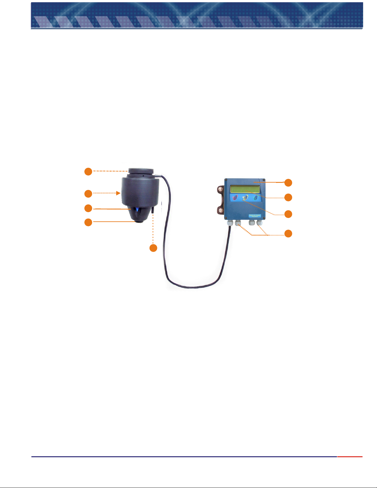
The equipment is offered in a compact cast aluminum case, SAE-323 with lower oxidation power,
treated against corrosion, finished with epoxy-electrostatic paint and expanded polypropylene panels
(PU). With reduced dimensions and very light weight, is build under IP-67 protection.
Under the same case, user will find: Local Indicator, Analyzer, Transmitter and Controller of ease
operation. The control installation can be done on Flat Surface or on 2" tube.
The electrical connection is made by a terminal block located at the lower portion of the controller and
cables will go thru 4 cable knockouts of 3/8" BSP.
Mechanical Description
5
1
8
6
7
9
PARTS DESCRIPTION:
1 - Frontal Lid in ABS
2 - Alphanumeric Display 2 lines x 16 characters
3 - 3 keys tactile membrane:
= Selects the desired option, flashing option.
<SELECT>
= Confirms the selected option chosen at SELECT key
<ENTER>
= Goes back one step or moves back to prior screen
<ESCAPE>
4 - Cable knockouts (4x) of 3/8" BSP for instrumentation and power cables
5 - Sensor / Turbidity Detector
6 - Bubble Trapper (to remove bubbles)
7 - Cleaning Drainage
8 - Sample Inlet Connection
9 - Sample Drainage
2
3
4
4
Page 6

4.
Turbidity Measurement Principles
TURBIDITY MEASUREMENT
The measured Turbidity of determined sample, is the reading referred by light
dispersed and absorption that goes thru the sample.
Turbidity does not mean suspended solids measurement, but a effect determination
of light refracted through solids.
Turbidity measurements are used to evaluate the quantity of water sample. To
understand turbidity it is helpful to think about the characteristics of mixtures.
A mixture is defined as Homogenous or Monophasic, when the components of
the mixture are uniformly dispersed, or dissolved, throughout the mixture, Salt water
is an example of a homogenous mixture or Solution. Heterogenous or Polyphasic
mixtures are those whose components are not well distributed throughout the
mixture. The components may simple be floating in the mixture, given enough time
these components will settle out. This type of mixture is also called Suspension.
The clarity of a water sample is directly related to the amount of material suspended in
the water. Turbidity measurements are a way to measure the amount of material
suspended in a water sample. They are commonly used to monitor the effectiveness of
filtration processes.
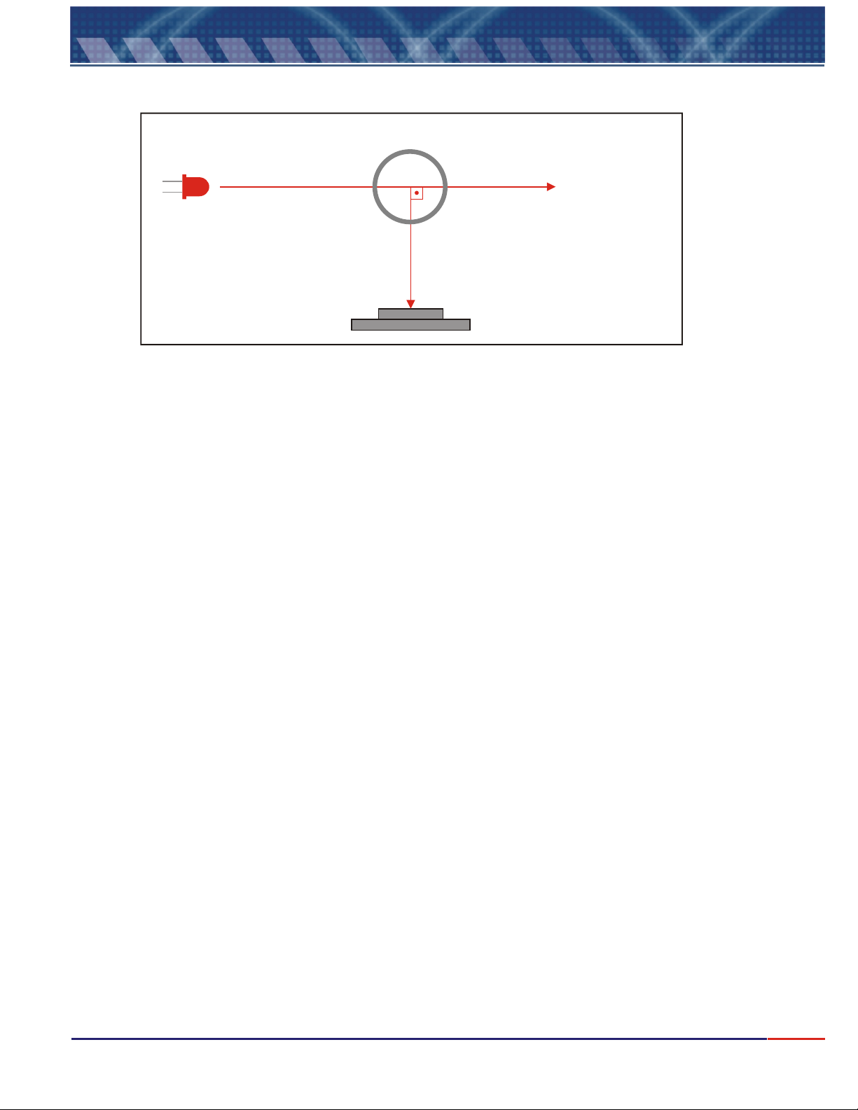
The OMEGA Turbidity meter uses the principle of Nephelometry. As light of a known
intensity is passed through a sample some of the light will be scattered by particles in the
sample. A detector is placed at 90° to the sample to collect the scattered light. The
intensity of the scattered light is compared to that of the source. This value is reported as
a Nephelometric Turbidity Unit, or NTU. The meter is calibrated with Formazine
standards of a known NTU.
Water can sometimes have color of its own (from humic sources, for example). This
color may interfere with the light source, absorbing some of the light, and reducing the
amount of light reaching the detector. This can cause the measurement to be skewed.
The OMEGA Turbidity Meter LED light source emits at a range close to infrared. In this
range absorption is minimized, and turbidity measurements are more accurate.
5
Page 7
4.
Turbidity Measurement Principles (cont.)
Vial
90°
Light Emitting
near “ IR”
Reflected Light @ 90°
Detector
As detection involves the difference between the light reaching the vial and
transmitted by the sample placed at the cuvette, it is convenient to minimize the effects
that diminish the light intensity transmitted, among those the most important, it is the
absorption caused by the samples color.
Because of this it is essential to work in a light wavelenght where absorption would be
minimum (close to infrared), if we work in a electromagnetic spectrum visible region, this
color interference would certainly alter the results.
In order to quantify the turbidity, we can use many comparison standards, being NTU
(Nephelometric Turbidity Unit) scale the most common, patronized from formazine
standard suspensions. This way we would have a comparison standard scale between
different materials, in a way we can evaluate turbidity with precision.
Transmitted
Light
Bibliographic References
Bela G. Lipták (chief editor) Analytical Instrumentation;
Howard A. Strobel and William R. Heineman, Chemical Instrumentation, A Systematic
Approach.
6
Page 8
5.
Dimensional
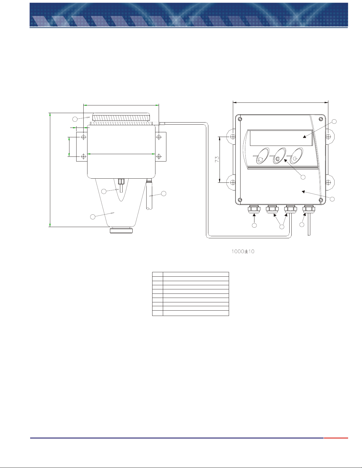
Below you will find panel dimensional for installation in flat surface and distances between support
holes.
180180
66
1515
4040
245245
88
157157
77
99
4
Cable Length
152152
2
3
1
Electrical
Power
5
4
Dimensions in Millimeters
ITEM
DESCRIPTION
9
Hose ½” Drainage
8
Bubble Trapper (remove bubbles) in Black PP
PU Hose - Diam. 6x1mm (Sample Inlet)
7
6
Turbidity Sensor / Detector
5
Cable Knockout 3/8” (2x)
Cable Knockout 3/8” (2x)
4
PU Tactile Membrane
3
Alphanumeric Display 2lines x 16characters
2
Frontal Lid in Resin
1
7
Page 9
6.
Equipment Installation
Follow rigorously below instructions:
1- Remove the equipment from its box and verify for any possible damages, caused by the
transportation.
2- Install the controller in a strategic place, of ease access and operation, free of vibrations and
vapors.
3- Avoid direct exposure of the controller to solar rays and in case if necessary, protect the controller.
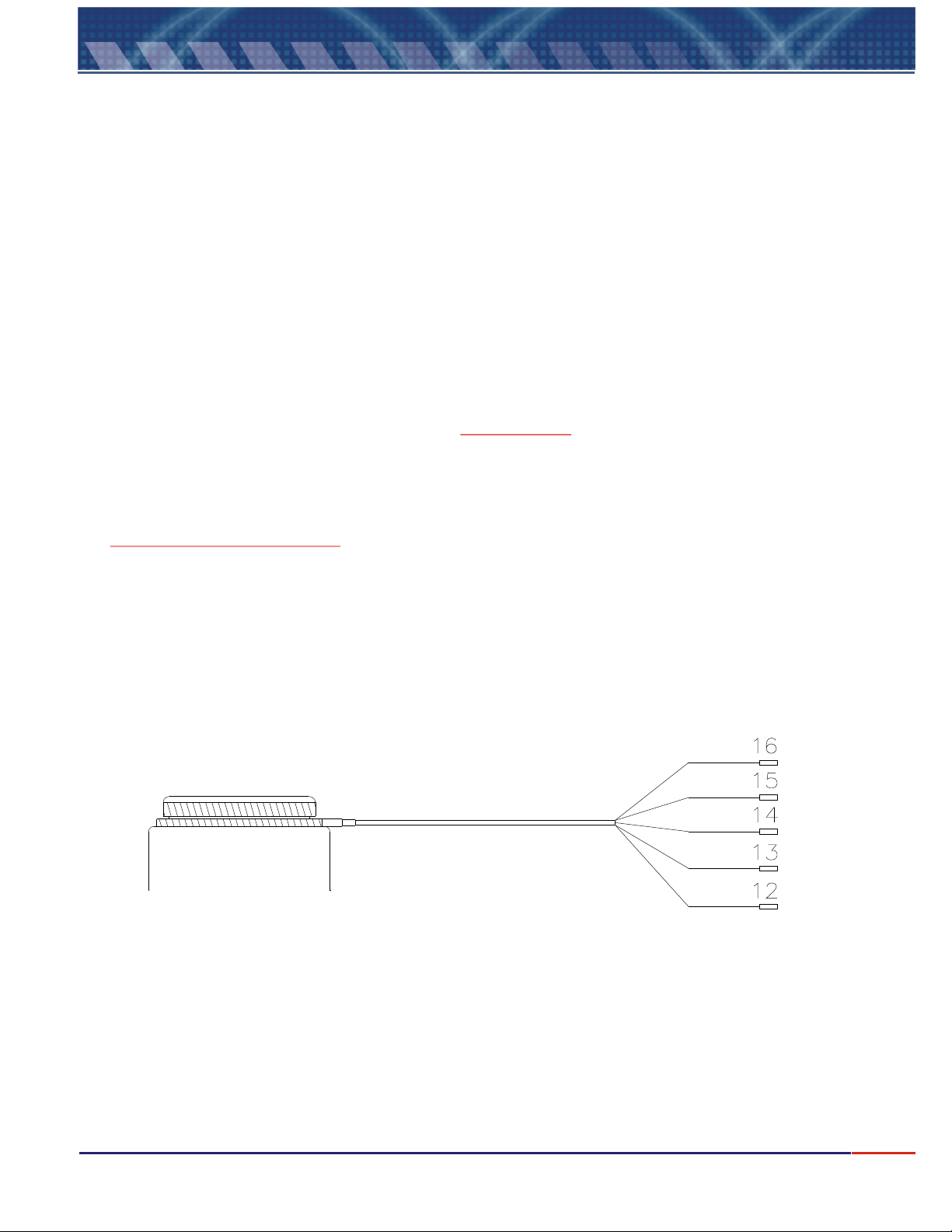
4- Proceed with terminal connections of cables at terminal barr.
5- Inspect the electrical installation in order to certify that all connections are correct.
6- Verify the power that is being supplied and make sure to connect it the proper place.
7- Connect the circuit breakers from the power distribution box.
3.1. Important Recommendations
3.1.1. The equipment must be Being
Electrical Power independent
from other system components.
so, the power cable of Control Valves, Solenoids, Alarms, etc, must be connected directly at the
Distribution Box, and "" at the equipment connection board.
3.1.2. if the equipment are providing the proper sealing to the cable inlets.
Verify cable knockouts
This proceeding is a must in order to preserve enclosure as
3.1.3. . It reduces impedance, generating measuring errors. Verify the
Be careful with Humidity!!
cable knockout and if necessary, using a hair dryer.
3.1.4. s length,
Do not cut or try to attach the connection cable.
never
IP-67.
dry the connection block
In case you need to change it
Contact OMEGA Customer Service.
RF Shield
Meas.
Sensor Cable
Electr. Shield
Yellow
Green
3.1.5. ON-OFF are , offering innumerous advantages for the equipment, such
outputs thyristor
type
as: no presence of sparks, faster commutation, noise practically un-existent, no presence of RF
interference and many more.
The outputs can commute any charge, since they are , l
250V / 1A
.
powered by alternate tension (VAC) imited to
8
Page 10
7.
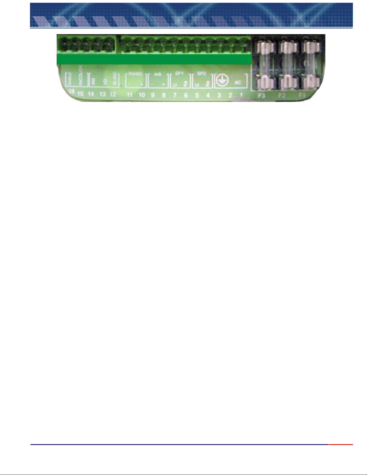
CN2 - Connector 2
Slots Connection
1 and 2 Electrical Power for 90/240 Vac 50/60Hz connection
3 Ground
4 and 5 SP2 - Set-Point 2 for alarm or control
6 and 7 SP1 - Set-Point 1 for alarm or control
8 and 9 Digital Transmission Output 4 to 20 mA
10 and 11 Serial Communication Output - RS485
CN1 - Connector 1
12 Turbidity Sensor Cable Shield
13 Green
14 Yellow
15 Measure (Colorless)
16 Turbidity Sensor Cable Shield
FUSES
F1 General Fuse (3.0A)
F2 Set-Point 2 Fuse (1.0 A)
F3 Set-Point 1 Fuse (1.0A)
Interconnection Barr
9
Page 11
8.
S
e
n
s
o
r
R
S
4
8
5
m
A
S
P
1
S
P
2
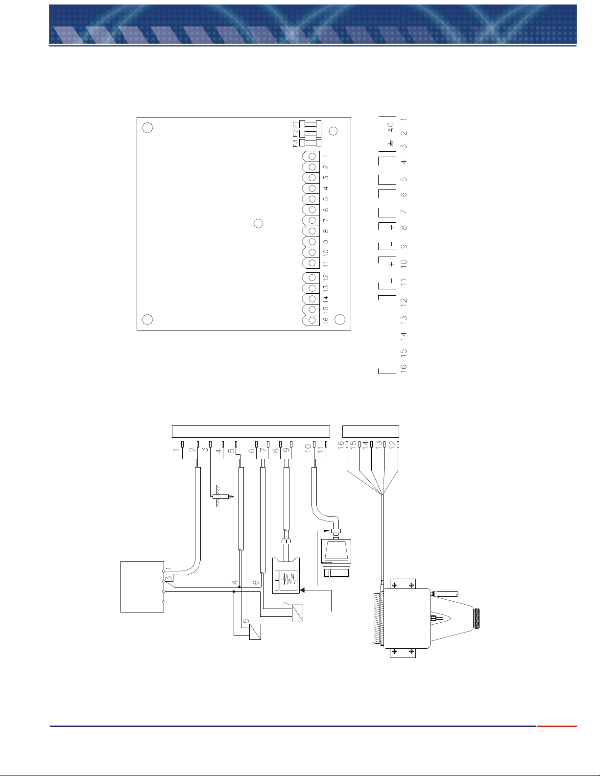
Electrical Schematic
Cn2
NO
C
NO
C
MAIN BOARD
Gre.
Connector Description
Yellow
Colorless
RF Shield
Cn1
Shie
Cn1
Power
90 - 240Vac
Female
Connetor
Cn2
Meas.
Yellow
Green
Ground
Cable 5
Cable 4
Cable 3
RF Shield
Electr. Shield
Cable 1
Cable 2
Detector
Cable 6
Converter
R
S
T
Box
Electrical
Note: It’s very important to
use phases and cables for
Equipments and valves.
N
Distribution
Controls
RS485/RS232
Microcomputer
or
Alarm
Graphic
SDLC
PLC or
Register or
Sensor / Turbidity
Bubble
Trapper
10
Page 12
9.
Lens and Bubble Trap Cleaning
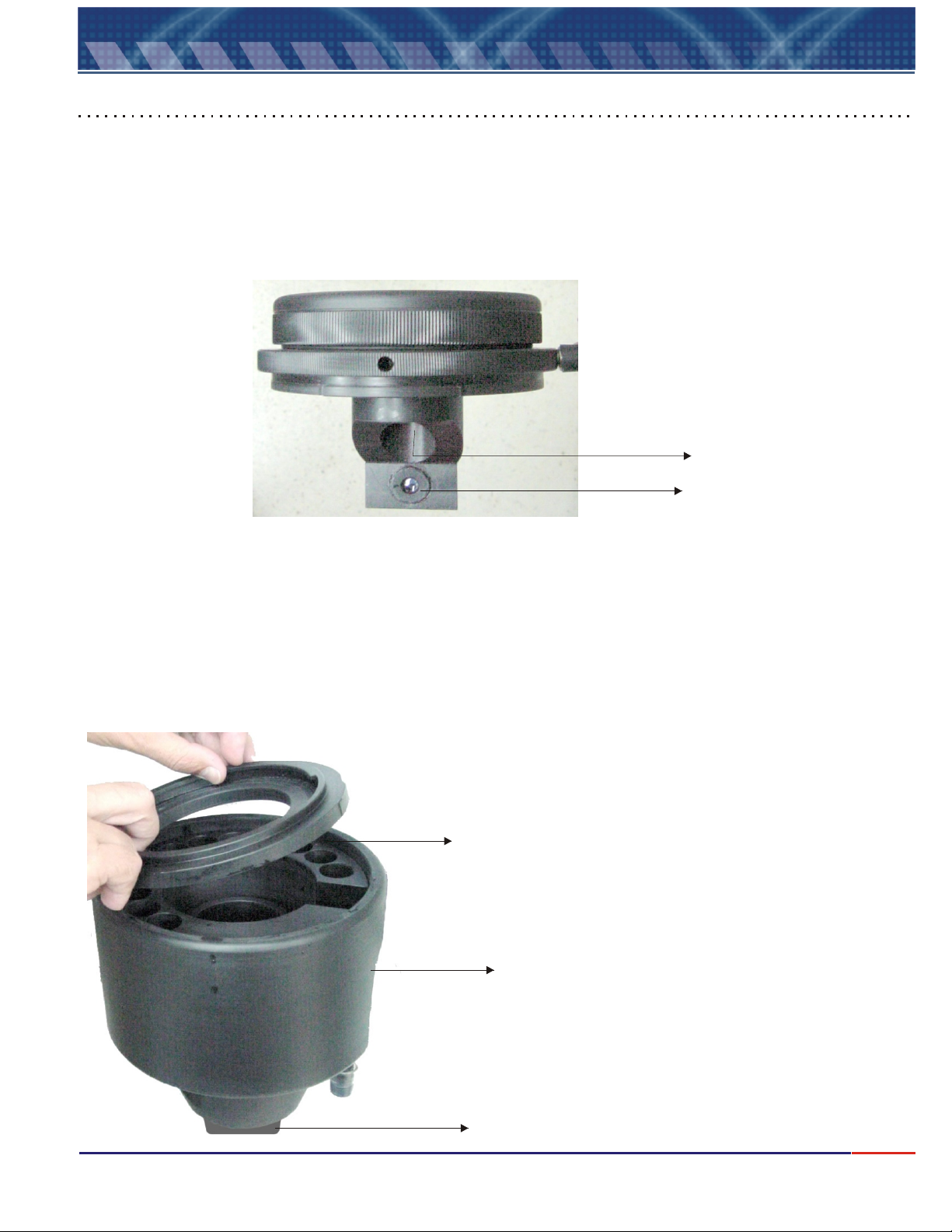
Sensor Unit Lens and Bubble Trapper Cleaning
LENS CLEANING OF SENSOR UNIT
Remove the Sensor/Turbidity Detector (5) by turning it clockwise (45degrees) and pull it up. Using a
soft sponge and neutral soap, wash the Led and the photocell Lenses. After this, dry it using a soft
Absorbent paper, a type that will not leave residues.
LED
Photocell
BUBBLE TRAPPER CLEANING
Clean the Bubble Trapper. Remove the locking ring, then un-thread the Drainage Lid, so the sample
can be drained from the instrument. Wash it using neutral soap and dry it using a soft absorbent
paper, a type that will not leave residues. Make sure to look for areas where residues can
accumulate (shown below picture). Remove the Bubble trapper as shown below and after cleaning
make sure to put it back in place!
Bubble Trapper
Body
Drainage Lid
11
Page 13
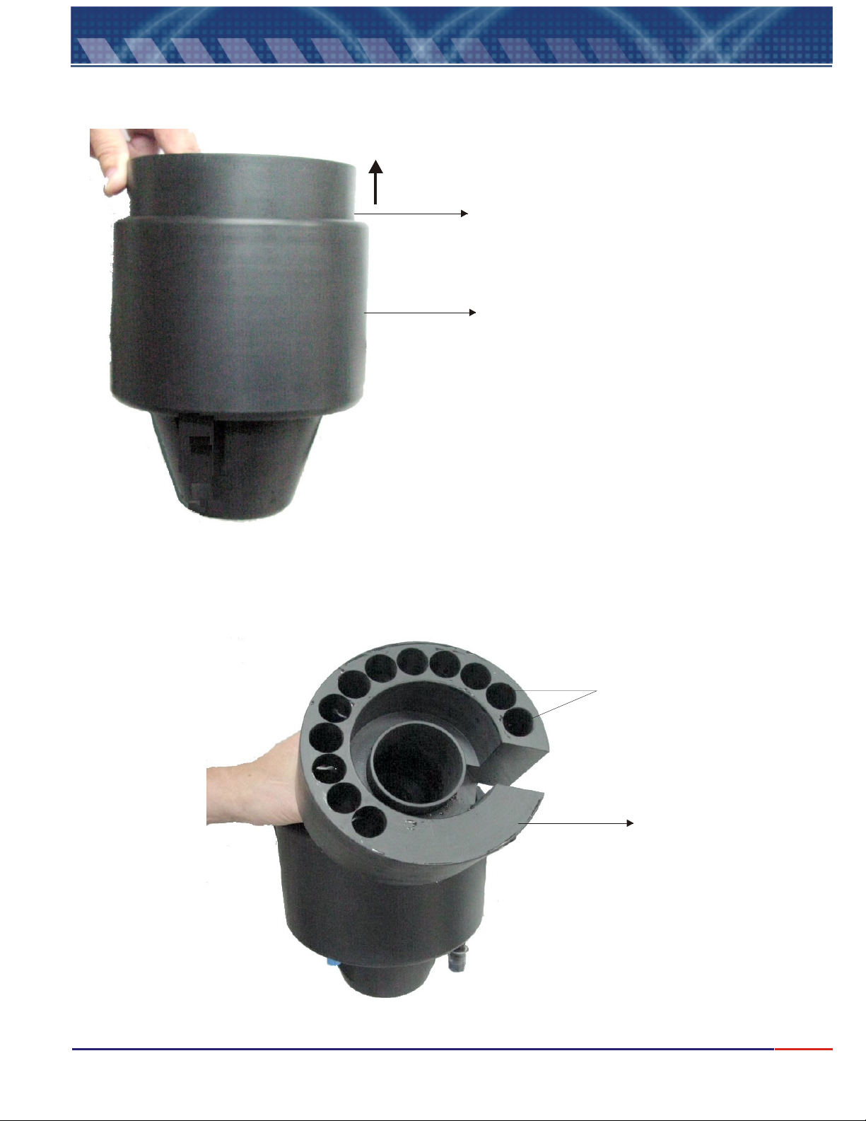
9.
Remove the Bubble Trapper by pulling it up.
Bubble Trap Cleaning (cont.)
Bubble Trapper
Body
Totally remove the Bubble Trapper from the body. Wash it using neutral soap and a small brush,
using circular movements, clean the openings. Rinse using plenty of water and dry it using a soft
absorbent paper, a type that will not leave residues. After the cleaning is done, re-install the Bubble
Trapper back at the body and proceed to calibration.
Openings
Bubble Trapper
12
Page 14
10.
1) Prepare the calibration standards need for your application (see page 14 for instructions on how to
formulate standards).
2) Close the process Sample Inlet.
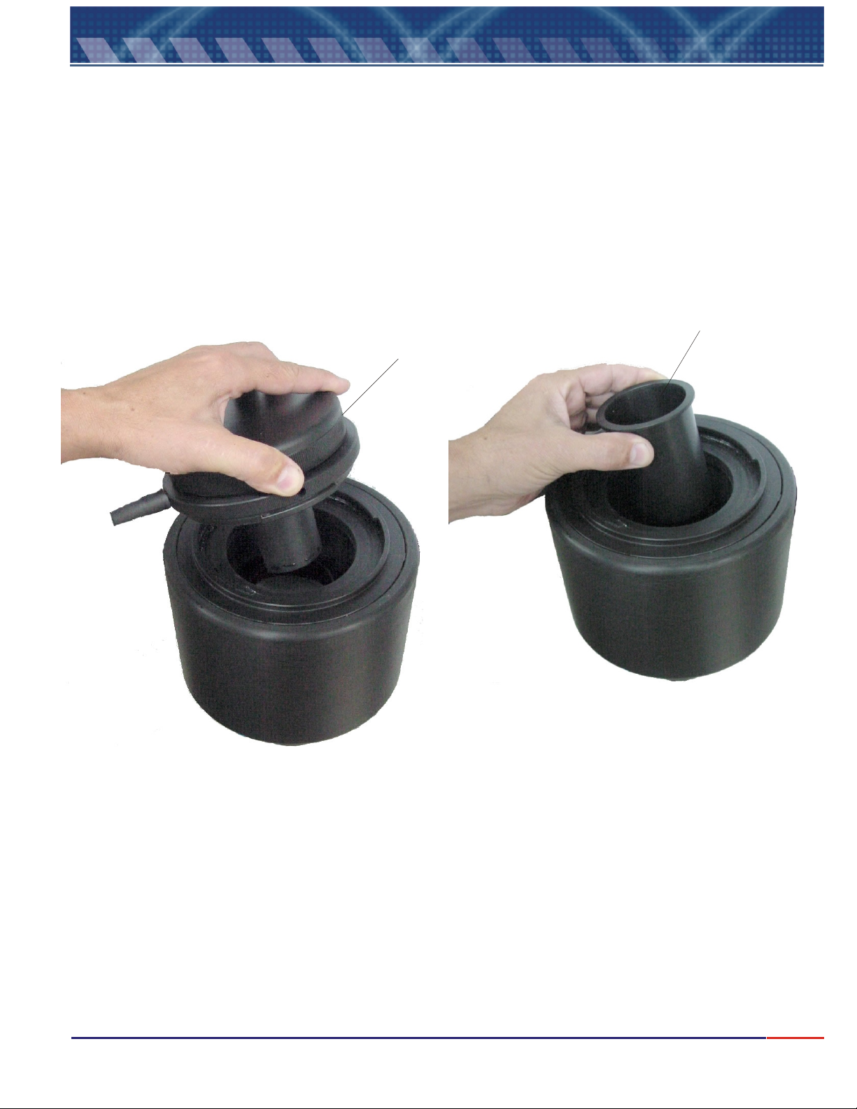
3) Un-thread the Drainage Lid, in order to remove the sample located inside the Bubble Trapper.
4) Remove the Sensor Unit from the Bubble Trapper and insert the calibration cup, as shown below.
Note: the calibration Cup MUST be clean! Residues FREE!
Calibration Information
Calibration Cup
Sensor Unit
Placing the Calibration Cup
Removing the Sensor Unit
5) Add the Turbidity Standard to the Calibration Cup, until it overflows some inches.
6) Replace the Sensor Unit back to the Bubble Trapper and wait about 15 seconds for stabilization.
7) Access the instrument calibration menu and execute the calibration steps (see page 20).
8) After the calibration is done, thread the Drainage Lid back in place. Remove the Sensor Unit and
take out the Calibration Cup.
8) Replace the Sensor Unit back at Bubble Trapper and open the Process Sample Inlet.
10) Execute Reading!
13
Page 15

11.
Turbidity Standard
Instructions on how to prepare Calibration Solutions
1. Standard Zero
In order to obtain a turbidity close to Zero, use a good quality deionized or distilled water and filter it twice in
a roll, using a 0.2
(Blank).
Note: this water will be used to dilute the standard.
2. Standard Solutions
The instrument is not supplied with a 100mL bottle of 1000NTU Stabilized Standard Solution, model# TRS444, for dilution and calibration purpose. The Formazine Standard should be ordered separate!
1 - Necessary Materials:
1.1 - 1 Volumetric Flask 100 mL
1 Volumetric Pipette 50 mL
2 L Distilled or Deionized Water, Filtered (0.2 µm)
2 - Calibration Solution 500 NTU
2.1 - In a 100ml Volumetric Flask, using the Volumetric Pipette add 50ml of 1000NTU Stabilized Standard
Solution.
2.2 - Add filtered water up to the mark on the flask.
2.3 - Before using the solution mix it by gently inverting the flask several times. Avoid creating bubbles.
2.4 - The Solution is Valid for 15 days.
Note:
place.
µm filter and teorically you will obtain a water with 0.12NTU, that can be considered Zero
For best storage conditions place the solution in a dark bottle and store it in a fresh and dark
3 - Calibration Solution 100 NTU
3.1 - In a 100ml Volumetric Flask, using the Volumetric Pipette add 10ml of 1000NTU Stabilized Standard
Solution.
3.2 - Add filtered water up to the mark on the flask.
3.3 - Before using the solution mix it by gently inverting the flask several times. Avoid creating bubbles.
3.4 - The Solution is Valid for 10 days.
3.5 - After its use, discharge the solution.
Note:
place.
4 - Calibration Solution 10 NTU
4.1 - In a 100ml Volumetric Flask, using the Volumetric Pipette add 1ml of 1000NTU Stabilized Standard
Solution.
4.2 - Add filtered water up to the mark on the flask.
4.3 - Before using the solution mix it by gently inverting the flask several times. Avoid creating bubbles.
4.4 - Stir it manually for before using it.
4.4 - The Solution is Valid for 5 days.
4.5 - After its use, discharge the solution.
Place.
For best storage conditions place the solution in a dark bottle and store it in a fresh and dark
Note:
For best storage conditions place the solution in a dark bottle and store it in a fresh and dark
Attention: for TURBIDITY, this instrument MUST BE calibrated using
Formazine Standard and cannot be calibrated using Polymers!!!
14
Page 16

12.
Equipment Operation
Set Up Procedures
The equipment offers a non-volatil memory (E2PROM), in order to store operations functions (resolution,
reading, Calibration and more). Even when turned off from power, all functions chosen during set up will remain
stored.
Before starting any work with the equipment, it is recommended to to certify
that you have chosen the correct options for the operation .
When at the , press key in order to select the desired function, flashing
option, then press , press key until SET function flashes, then
press . A Password will be requested, press in sequence ,
<ENT>
flashing option, press key until the desired option flashes then press
In order to move to the next screen, user must press .
SELECT FUNCTION
<ENT>
<ENT>
, then follow step by step the options shown at the screen. In case the user desires to change the
key to confirm the option chosen
<ESC>
key. In order to access the
<SEL>
menu
<SEL>
SET UP
<ENT>
key
verify the SET UP parameters,
<SEL>
<SEL>
<ENT>
key to confirm the option.
Read Operation
At this operation user will have options to and . In case the desire is to , press
<SEL>
guide the user step by step on how to proceed with the perfect calibration. In case the desire is to Read, press key
until option key to confirm, then the display show the following form:
<ENT>
key until . From this point on the program will
Read
option flashes, then press key to confirm the option chosen
Cal
flashes, then press
CALIBRATE READ CALIBRATE
<ENT>
4
the Sensor
<SEL>
»»» »»»
-> »»»»»» »»»
1
1- The "Prompt" is a signal that flashes every time a reading is performed.
2- The measured value
3- The Unit (NTU)
4- Contact Outputs Conditions
2
3
15
Page 17
12.
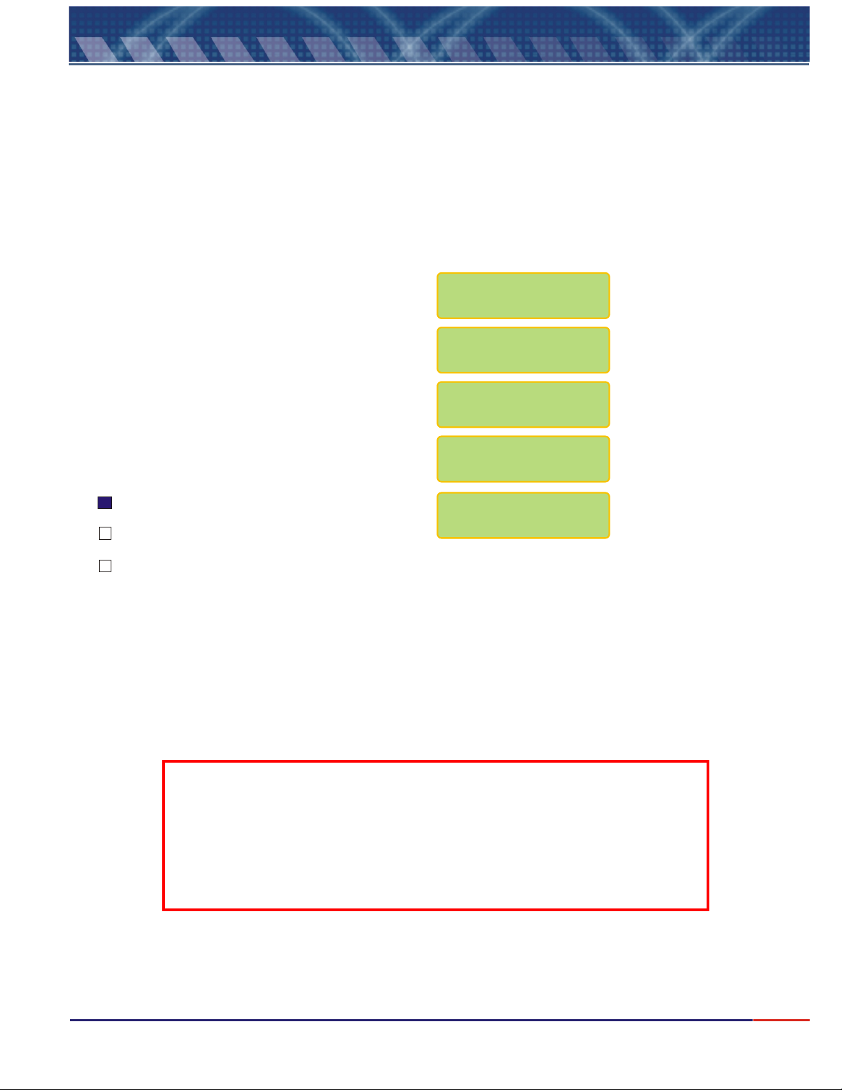
Equipment Operation - Turning On
menus are self explanatory with its respective options, that are simply selected by pressing
T
<SELECT>
key. After choosing the selection (flashing option), press key, to confirm
<ENTER>
the slected option.
If a mistake occur or user desires to change option already chosen, press , to go back to
<ESCAPE>
prior step. At every touch the screen will move back one step back. While in Reading Mode,
SCAPE>
<E 6 seconds to exit this mode and return to main
key must be pressed and hold for about
menu.
OMEGA
MOD:TRCN443 V1.0
DISPLAY TEST
»»»»»»»»»»»»»»»»
»»»»»»»»»»»»»»»»
Interpreting the Read menu. The Set Points will be
displayed and by the box on the side of each
contact, user can find out the status of these
contacts.
Indicates that the contact is On and operating at
the moment.
Indicates that the contact is On but not operating
at the moment.
Indicates that this contact was set as Off
X
All contacts are programed during Set Up Mode.
Press <ESC> key and hold in order to exit the
Reading Mode and access the Main Menu.
S1:» S2:»
-> 0.0001 NTU
TURBIDIMETER
/SET UPREAD
NOTE:
While during Reading, press key and the instrument will go to , turning off the
<ENTER> STAND-BY
alarm and control outputs.
Note A - Every time you see the symbols “ ” “ ”, that means that the user can
adjust the displayed value up or down.
To increase the value press key until “ ” flashes, then press to
confirm, then press key and at every touch the value will increase by one
unit.
To decrease the value press key until “ ” flashes, then press to
confirm, then press key and at every touch the value will decrease by one
unit.
If a mistake is made, press key to return and correct the value!
<SEL>
<SEL>
<SEL>
<SEL>
<ESC>
>> and <
<
<ENT>
<ENT>
16
Page 18
12.
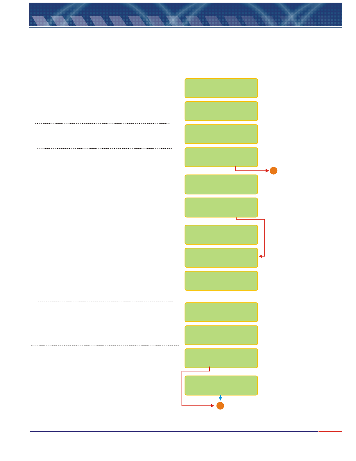
Press until flashes then press
<ENT>
Equipment Operation - Set Up
<SEL> Set Up
key.
TURBIDIMETER
READ/SET UP
A Password is required in order to access the
UP <SEL> <ENT> <ESC>
. Press in sequence , and
In order to select the desired language, press
<SEL>
press key to confirm.
User can program the instrument, such as Default
Calibration, On Line Calibration and more. If chosen ,
the last configuration will remain in effect. Press
key until the desired option flashes, then press
Key to confirm .
The Range cannot be changed. It is default from
key until the desired option flashes, then
<ENT>
You can calibrate the instrument as factory default.
Choose and confirm and the instrument will
calibrate as factory default! This option is offered in
case the user does have any other way to perform
a calibration procedure.
The user will be allowed to adjust the Turbidity
value read at sample. Press until
flashes then confirm by presssing .
Yes
<SEL> MAN
<ENT>
SET
No
<SEL>
<ENT>
PASSWORD
___
LANG.: PORT./
/SPANISHENGLISH
CONFIG. INSTR.?
/ YES NO
RANGE
0 - 10 NTU
FACTORY DEFAULT?
/ YES NO
CONFIRM?
/ YES NO
ON LINE CAL.:
MANUAL / AUTO
Go to Page 18
A
User will be able to choose the number of calibration
Points. Press key until the desired opiton
flashes and confirmed by pressing
User will be able to adjust the value of the
calibration points chosen. Refer to page 16 (Note
A) for instructions on how adjust this value.
User can choose between the following Reading Modes:
Continuous - Read continuously after time is set
Average - Reads the average after time is set
User can program the time between Readings for
Average Reading.
Refer to Page 16 (Note A) for instructions on how to
adjust this time.
<SEL>
<ENT>.
CAL. POINTS:
1 / / 32
CALIBRATION
Pt.1 0.3000NTU<>
CALIBRATION
Pt.2 1.0000NTU<>
READING MODE:
/CONTIN. AVER.
TIME BETWEEN
READINGS:5s <>
A
Go to Page 18
17
Page 19
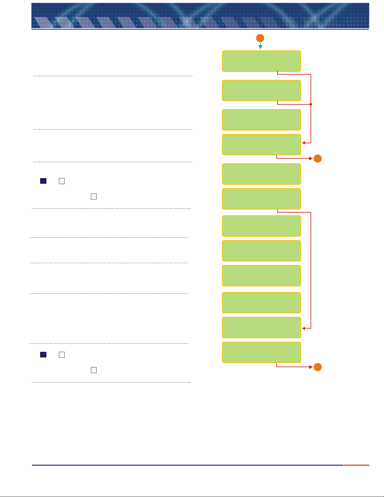
12.
Equipment Operation - Set Up (cont.)
From Page 17
A
User can program the display to show information like
Barr graph, Clock and more.
User can choose if desire to have Barr graph shown
above the Reading screen. When Bar Graph is
displayed, the information about Sensibility and Sample
Temperature will not be displayed!
User can now adjust the Minimum and Maximum
values for the Bar Graph. Refer to Page 16 (Note A) for
instructions on how to modify these values.
User has the option to configure Contacts SP 1and SP 2.
Press key to choose the desired option then
<SELECT>
press key to confirm.
<ENTER>
If user chooses Contact S1 as On, while at Reading Mode,
a or a will be displayed after the S1, indicating that
this Contact is On. If user chooses Contact S1 as Off, while
at Reading Mode, a will be
User can adjust the value for SP 1.
Refer to Page 16 (Note A) for instruction on how to adjust
this value. Resolution will depend upon the Resolution
chosen while at Set Up.
User can choose the Acting desired.
Press key to choose the desired option then
<SELECT>
press key to confirm
<ENTER>
X
DISPLAY CONFIG.?
/ YES NO
BARGRAPH?
/ YES NO
Min:0.0000NTU
Max:10.0000NTU
CONTACTS CONFIG?
/ YES NO
CONFIG. CONTACT
S1
CONFIG. S1:
/OFFON
SET POINT S1:
5.0000 NTU <>
ACTING:
/REVERSEDIRECT
<
>
<
>
Go to Page 19
A
User can adjust the value for Hystereses.
Refer to Page 16 (note A)for instruction on how to adjust
this value. Resolution will depend upon the Resolution
chosen while at Set Up.
For the Burn Out configuration, user will have three options as:
On - Contact is going to stay On all the time, Off - contact will stay
Off all the time or Hold - contact is going to follow the last situation,
before going to Hold status.
<SEL>
Press key until the desired option flashes, then press
<ENT>
If user chooses Contact S2 as On, while at Reading Mode,
a or a will be displayed after the S1, indicating that
this Contact is On. If user chooses Contact S1 as Off, while
at Reading Mode, a will be
to confirm.
X
HYSTERESE:
0.0000NTU <>
BURN-OUT CONFIG.
STAND-BY: HOLD
CONFIG. CONTACT
S2
CONFIG. S2:
/OFFON
Got to Page 19
A
18
Page 20
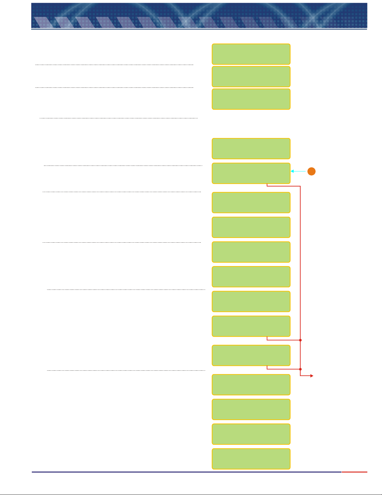
12.
User can adjust the value for SP 2.
Refer to Page 16 (Note A) for instruction on how to adjust
this value. Resolution will depend upon the Resolution
chosen while at Set Up.
Equipment Operation - Set Up (cont.)
SET POINT S2:
20.0000 NTU <>
User can choose the Acting desired.
Press key to choose the desired option then
<SELECT>
press key to confirm
<ENTER>
User can adjust the value for Hystereses.
Refer to Page 16 (note A)for instruction on how to adjust
this value. Resolution will depend upon the Resolution
chosen while at Set Up.
For the Burn Out configuration, user will have three options as:
On - Contact is going to stay On all the time, Off - contact will stay
Off all the time or Hold - contact is going to follow the last situation,
before going to Hold status.
Press key until the desired option flashes, then press
<SEL>
<ENT>
to confirm.
User has the option to configure Current.
Press key to choose the desired option then
<SELECT>
press key to confirm.
<ENTER>
User has the option to choose using Output mA.
<SELECT>
Press key to choose the desired option then
<ENTER>
press key to confirm.
User can adjust the value the values for 4 and 20mA
Current Output.
Refer to Page 16 (Note A) for instruction on how to adjust
this value. Resolution will depend upon the Resolution
chosen while at Set Up.
ACTING:
/REVERSEDIRECT
HYSTERESE:
0.0000NTU <>
BURN-OUT CONFIG:
STAND-BY: HOLD
CURRENT CONFIG.?
/ YES NO
OUTPUT CONFIG.:
mA
MA OUTPUT:
/ON OFF
VALUE FOR 4 mA
0.0000NTU <>
VALUE FOR 20 mA
5.0000NTU <>
From Page 18
A
For the Burn Out configuration, user will have three options
as: 4mA, 20mA or Hold.
<SEL>
Press key until the desired option flashes, then
<ENT>
press to confirm.
User will be able to calibrate mA output.
Press key to choose the desired option then
<SELECT>
press key to confirm
<ENTER>
Connect Amp Meter to output 4-20mA and it will be possible
to adjust them, then press <ENTER> when ready.
Adjust the value as needed by pressing (to
decrease) or (to increase) keys, so the outputs
can be adjusted.
<SELECT>
will increase.
<ESCAPE>
<ESCAPE>
key will decrease the value and key
<SELECT>
BURN-OUT CONFIG:
STAND-BY:4mA
CALIBRATE mA?
/ YES NO
CONFIRM?
/ YES NO
PLACE AMP METER
@ OUTPUT 4-20 mA
READY?
ADJUST 4 mA
<SEL>- <ESC>+
ADJUST 20 mA
<SEL>- <ESC>+
Go to Page 20
19
Page 21
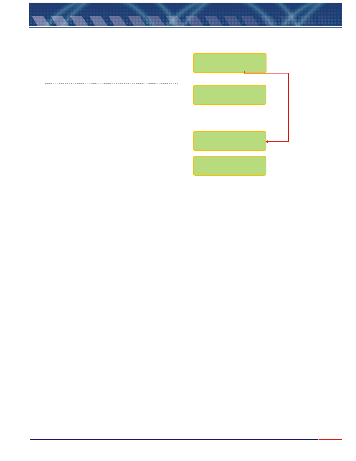
12.
Equipment Operation - Set Up (cont.)
User will have the option to configure digital output RS-485
for Proprietary or Modbus Protocol. Press key
to choose the desired option then press key to
confirm .
User will be able to define the instrument identification
number within the network, up to 32 instruments. Refer to
Page 13 for instruction on how to adjust this value.
This output is for Proprietary Protocol Communication with
Speed (9600), No Parity, Bit 8 and Stop Bit 1. Refer to Page
22.
<SELECT>
<ENTER>
RS-485 CONFIG.?
COMMUNICATION-ID
NUMBER 1 <>
TURBIDIMETER
READ/SET UP
/ YES NO
WAIT
20
Page 22
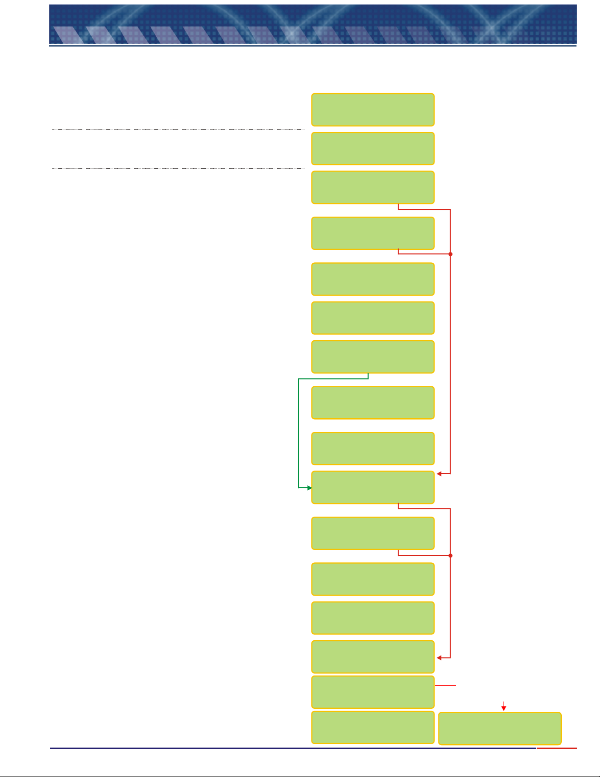
12.
Equipment Operation - Calibration
Before initiating the Calibrtion Procedure, preapre the Standard Solutions and have the deionized water
ready. Also clean the Calibration Reservoir using deionized waterat every change of Standard Solution.
Press until flashes then press key. <SEL> Read <ENT>
Press until flashes then press
<SEL> Calibrate <ENT>
key.
Follow intructions as per page 13, dip the Standard
Solution on the value shown, this Std Solution is chosen
<SEL>
during Set Up Mode. Press until desired opiton
<ENT>
flashes then press key. User will still have the
option to accept this calibration point or not!
<ENT>
Press key to confirm.
Place the sensor unit, as per instruciton on page 13, into
the Standard value shown. This Std Solution is chosen
during Set Up Mode. Press until desired opiton
flashes then press key.
<ENT>
Press key to confirm.
<ENT>
<SEL>
TURBIDIMETER
/SET UPREAD
TURBIDIMETER
READ/CALIBRATE
CAL. 0.3000 NTU?
/ YES NO
CONFIRM ?
/ YES NO
PLACE SENSOR
@ 0.3000 NTU
READY ?
================
WAIT
The equipment will analyze the Standard Solution and
If it does not match the instrument linarity, it will inform
the user about its quality, but if the user decides to use
this solution, he will be able to do so!
Follow intructions as per page 13, dip the Standard
Solution on the value shown, this Std Solution is chosen
<SEL>
during Set Up Mode. Press until desired opiton
<ENT>
flashes then press key. User will still have the
option to accept this calibration point or not!
<ENT>
Press key to confirm.
Place the sensor unit, as per instruciton on page 13, into
the Standard value sown. Tthis Std Solution is chosen
during Set Up Mode. Press until desired opiton
flashes then press key.
<ENT>
Press key to confirm.
Remove the sensor from the bubble trapper, remove the
Calibration cup. Re-insert the sensor into the trapper,
open the process and proceed with Readings.
<ENT>
<SEL>
NON CONFORMANCE
STANDARD <ENTER>
CONFIRM STAND.?
/ YES NO
Standard in conformance
CAL.:1.0000 NTU?
/ YES NO
CONFIRM ?
/ YES NO
PLACE SENSOR
@ 1.0000 NTU
READY ?
================
WAIT
GO TO SAMPLE!
READY ?
================
->8.4390 NTU
Indicates when the
Bargraph was not chosen
during Set Up Mode.
S1:» S2:»
-> 8.4390 NTU
21
Page 23
12.
Equipment Operation - Read
Find below instructions on how to perform a Turbidity Reading. Before starting, verify if the bubble
trapper is clean, if the drain hose is connected and “open” and if the sample is flowing correctly.
Finally insert the sensor unit at the bubble trapper and lock it by turning it counter clockwise
(45degrres).
Press until flashes then press key. <SEL> Read <ENT>
TURBIDIMETER
/SET UPREAD
Press until flashes then press key. <SEL> Read <ENT>
TURBIDIMETER
READ/CALIBRATE
Verify if sample is flowing and drain hose is connected,
then press <ENT> key to start Reading Mode.
GO TO SAMPLE!
READY?
================
Press key to place the equipment in Stand By. <ENT>
-> 0.0035 NTU
STAND BY
Press key to exit Stand By and return to Read Mode. <ENT>
================
-> 8.5100 NTU
Press key to verify the Contact and Current
<SEL>
conditions.
S1:» S2:»
-> 4.83 mA
<SEL>
Press and it will be able to adjust the value
Read, if chosen this procedure during Set Up Mode
(On Line Calibration-page 17). Refer to page 16
(Note A) for instructions on how to adjust this value.
ON LINE CALIBR.
8.5100 NTU <>
================
-> 8.5160 NTU
Indicates when the
Bargraph was not chosen
during Set Up Mode.
S1:» S2:»
-> 0.0035 NTU
In order to exist the reading Mode, press and hold <ESC>
key. User will then access the main menu.
TURBIDIMETER
/SET UPREAD
22
Page 24

13.
Proprietary Communication Protocol
Communication Protocol (TRCN-443):
1) Proprietary:
Order:
ESC ID P CR LF
0x1B 0x50 0x0D 0x0A Hexadecimal
The ID is configured at the instrument from 1 to 32.
Answer:
L > > V V V V V V N T U C C C C C C m A
Example of answer for an un-stable value (for low turbidity 0 – 10NTU)
L > 0.001 N T U 1 2 . 0 0 m A
Example of answer for a stable value (for low turbidity 0 – 10NTU)
L > > 0.001 N T U 1 2 . 0 0 m A
Note: a) When the answer comes a C instead of a L, it means that the equipment is under
calibration function (is being operated in location by the user, executing the calibration
operation at the instrument).
b) When the answer comes an S instead of a L, it means that the equipment is under Set Up
function and it is being operated in location by the user.
2) RS485 – It is a “physical location”, where the proprietary protocol will be “transported”.
As factory default, this communication comes configured as:
Speed = 9600
Parity = none
Number of Bits = 8
Stop Bit = 1
ID = 1
23
Page 25
Page 26

M-4513/0908
 Loading...