

Page 1

.
Series TCL-650S-D / TCL-165S-D
TCL-M165S-B / TCL-M255S-B
Temperature Calibrator
Page 2

Series TCL
- 2 -
Page 3

Series TCL
Table of contents page
0 About this operating manual ...................................................................................... 5
1 Device description ..................................................................................................... 6
1.1 Delivery, unpacking and accessories ...................................................................... 7
1.2 Intended use............................................................................................................ 8
1.3 Exclusion of liability ................................................................................................. 8
2 Safety Instructions ..................................................................................................... 9
2.1 Safety instructions for the application of calibration liquids ................................... 11
3 Construction and function ........................................................................................ 12
3.1 Construction .......................................................................................................... 12
3.2 Functions ............................................................................................................... 13
3.3 Data interface ........................................................................................................ 13
4 Commissioning and operation ................................................................................. 15
4.1 Operating conditions ............................................................................................. 15
4.2 Electrical connection ............................................................................................. 16
4.3 Preparation of the calibrator .................................................................................. 17
4.3.1 Dry block calibrator ........................................................................................... 18
4.3.2 Micro bath calibrator .......................................................................................... 19
4.4 Switching on, cool down and switching off ............................................................ 23
4.5 Operating modes ................................................................................................... 24
5 Operation ................................................................................................................. 25
5.1 Control elements of the controller .......................................................................... 25
5.2 Calibration (calibration mode)................................................................................ 26
5.2.1 Display of reference and set temperature ......................................................... 26
5.2.2 Display of temperature control .......................................................................... 26
5.2.3 Display of fan/ cooling contr ol ........................................................................... 27
5.2.4 Display of heating / cooling capacity and operating duration ............................ 27
5.2.5 ConF menu ....................................................................................................... 27
5.3 Set a temporary set temperature (set point mode) ................................................ 28
5.4 Main menu ............................................................................................................ 29
5.4.1 Automatic control .............................................................................................. 31
5.4.2 Manual control ................................................................................................... 32
5.4.3 Stored Set point values ..................................................................................... 33
5.4.4 Gradient control / temperature profile ................................................................ 34
Technical changes reserved - 3 -
Page 4

Series TCL
Copyright notice:
The reproduction, distribution and utilization of this operating manual
its contents to others without express authorization is prohibited. Offenders will be held liable for the
payment of damages. All rights reserved in the event of the grant of a patent, utility model or design.
6 Testing process / Calibration ................................................................................... 40
6.1 Testing temperature sensors................................................................................. 40
6.2 Testing process ..................................................................................................... 40
7 Problems ................................................................................................................. 42
7.1 Return shipment to the manufacturer .................................................................... 43
8 Maintenance, cleaning and transport ...................................................................... 44
8.1 Maintenance.......................................................................................................... 44
8.1.1 Recalibration ..................................................................................................... 45
8.2 Cleaning ................................................................................................................ 46
8.3 Transport ............................................................................................................... 47
9 Decommissioning and di spos al ............................................................................... 48
10 Technical data ......................................................................................................... 49
10.1 Shared characteristics ........................................................................................... 49
10.2 Characteristic s TLC-650S-D and TLC165S-D....................................................... 50
10.3 Characteristics series TCL-M165S-B and TCL-M255S-B ..................................... 51
10.4 Heating and cooling periods .................................................................................. 51
10.4.1 TCL-165S-D (dry block) .................................................................................... 52
10.4.2 TCL-650S-D (dry block) .................................................................................... 53
10.4.3 TCL-M165S-B (Water and silicone oil) .............................................................. 54
10.4.4 TCL-M255S-B (Water and silicone oil) .............................................................. 55
as well as the communication of
- 4 -
Page 5

Series TCL About this operating manual
e-mail: [email protected]
DANGER! Risk of death due to electric current!
WARNING! / CAUTION! Risk of injur y!
cause considerable damage to property.
CAUTION! High temperature!
considerable damage to property.
CAUTION! Material damage!
damage.
NOTICE!
NO DOMESTIC WASTE!
Pay attention to and comply with
Check the specified points or notices.
0 About this operating manua l
• The operating manual is aimed at specialists and semi-skil l ed pers o nnel .
• Before each step, read through the relevant advice carefully and keep to the specified
order.
• Thoroughly read and understand the inform ation in the section "Safety Instructions".
If you have any problems or questions, please contact your supplier or contact us directly
at:
Omega.com
Tel: (203) 359-1660
Hazard signs and other symbols used:
This sign indicates dangers which could lead to serious health defects or to death.
This sign indicates dangers that cause personal injuries that can lead to health defects or
This sign indicates dangers resulting from high temperature that can lead to health defects or
This sign indicates actions which could lead to possible damage to material or environmental
ADHERE TO OPERATING MANUAL!
The device must not be disposed of
together with domestic waste.
information that is marked with this symbol.
Follow the specified instructions and steps.
Adhere to the given order.
This symbol indicates important notices,
tips o r i nformation.
Reference to another section, document or
source.
• Item.
Technical changes reserved - 5 -
Page 6
Device description Series TCL
Heating
Cooling and heating
Dry block calibrators
TCL-650S-D
TCL-165S-D
Micro bath calibrators
TCL-M255S-B
TCL-M165S-B
Dry block calibrators
Micro bath calibrators
TCL-165S-D
TCL-650S-D
TCL-165S-B
TCL-255S-B
1 Device description
The TCL series of calibrators test and calibrate different temperature measuring instruments
and temperature sensor s , and meas ur e tem per atures.
The portable instruments are of compact and robust construction and thus allow use directly
on-site or in a laboratory.
The TCL series is used for service purposes and for different industrial and laboratory tasks.
For example, thermometers, temperature switches/thermostats, resistance thermometers
and thermo-elements can be directly connected and checked.
Versions:
The TCL series of calibrators include the follow i ng dry block / micro bath types:
Type plate:
You find the type plate on the rear of the device.
It includes the type designation, the serial number and the key electric specifications
(example Fig.).
- 6 -
Page 7

Series TCL Device description
Dry block calibrator according to order
Micro bath calibrator according to order data.
Protective packaging and transport protection.
1.1 Delivery, unpacking and accessories
All units have been carefully checked for their operational reliability before shipment.
Immediately after receipt, please check the outer packaging for damages or any signs of
improper handling.
Report any possible damages to the forwarder and your responsible sales representative.
In such a case, state a description of the defect, the type and the serial number of the
device.
Report any in-transit damage immediately. Damage reported at a later date shall not be
recognized.
Unpacking:
Carefully unpack the unit to prevent any damage.
Check the completeness of the delivery based on the delivery note.
Save the packaging!
Temperature calibrators are delivered in special protective packaging.
Save the packaging for returning the instrument safely to the manufacturer for
recalibration or repai r .
Scope of delivery and accessories (included):
Dry block calibrator: Micro bath:
data.
Power cable.
Sleeve exchange tools.
Test certificate.
Operating manual.
Protective packaging and transport
protection.
Power cable.
Seal cover.
Work cover with five silicone plugs.
Sensor cage.
Magnetic stirrer.
Magnetic lifter.
Drain syringe.
Test certificate.
Operating manual.
IMPORTANT!
Use the type plate to check if the delivered unit corresponds to your order.
In particular, for devices with electrical components, check to see if the correct power
supply voltage is specified.
Technical changes reserved - 7 -
Page 8

Device description Series TCL
1.2 Intended use
The TCL series of calibrators may only be used for testing and calibration of suitable
temperature measuring instruments, temperature sensors and for measuring temperatures.
The calibrators may not be used for warming up or heating other parts or gases.
The calibrators have been designed for indoor use only.
The micro baths may only be used with suitable media. Permitted liquids are silicone oils,
mineral oils and water ( § 2.1 "Safety instructions for the application of calibration liquids").
Hazardous media (flammable or explosive liquids or gases) may not be used.
The operational safety of the device supplied is only guaranteed by intended use. The
specified limits ( § 10 "Technical data") may under no circumstances be exceeded.
CAUTION! Risk of burns!
The calibrator can become very hot when in operation. Touching hot parts can result in
serious injuries.
Never touch the metal block, the tank, the adapter sleeve or the test specimen at
temperatures above 35 °C or below 10 °C (95 °F or below 50 °F).
Allow the calibrator to cool before you remove the test specimen, clean the tank,
change the adapter sleeve or the calibration insert or switch off the machine.
CAUTION! Material damage!
The opening in the metal block of the calibrator is only intended to be used with adapter
sleeves or calibration inserts.
Using heat transfer media (oil, thermal paste or other media) can lead to incorrect
measurements and damage to the calibrator.
Never fill the metal block opening with a heat transfer medium.
Only micro baths are suitable for use with heat transfer medium.
It is your responsibility to select the instrument which is suitable for your specific application,
to connect it correctly, to carry out tests and to maintain all the components.
1.3 Exclusion of liability
Omega accepts no liability for any damage or malfunctions resulting from incorrect
installation, in-appropriate use of the device or failure to follow the instructions in this
operating manual.
- 8 -
Page 9
Series TCL Safety Instructions
2 Safety Instructions
Before you install the TCL, read through this operating manual carefully. If the
instructions contained within are not followed, in particular the safety guidelines, this
could result in danger for people, the environment, and the device and the system it is
connected to.
The TCL corresponds to the state-of-the-art technology. This concerns the accuracy, the
operating mode and the safe operation of the device.
In order to guarantee that the device operates safely, the operator must act competently and
be conscious of safety issues.
OMEGA ENGINEERING provides support for the use of its products either personally or via
relevant literature. The customer verifies that our product is fit for purpose based on our
technical information. The customer performs customer-specific and application-specific tests
to ensure that the product is suitable for the intended use. With this verification all hazards and
risks are transferred to our customers; our warranty is not valid.
Qualified personnel:
The personnel in charge of the installation, operati on an d mai nt ena nce of the TCL must
hold a relevant qualification. This can be based on training or relevant instructions.
Personnel must be aware of this operating manual and have access to it at all times.
The electrical connection should only be carried out by a fully qualified electrician.
General safety instructions:
In all work, the existing National regulations for accident prevention and safety in the
workplace must be complied with. Any internal regul ati ons o f the oper at or mus t al so be
complied with, even if these are not mentioned in this manual.
Ensure that the complete operating instructions are always available in excellent condition
at the calibrator installation site.
Degree of protection according to EN 60529:
Ensure that the ambient conditions at the site of use do not exceed the requirements for
the stated protection rating ( § 10 "Technical data").
Structural safety in accordance with EN 61010-1:
The calibrator must be installed in such a way that the requirements for structural safety
are met.
Only use the TCL if it is in perfect condition. Damaged or faulty devices must be checked
without delay and, if necessary, replaced.
If problems cannot be cleared, immediately shut down the calibrator and ensure that it
cannot be started up accidentally.
Never leave the calibrator unattended when it is in operation or in the cooling phase.
Do not remove or destroy type plates or other markings on the device, or the warranty is
rendered null and void.
Technical changes reserved - 9 -
Page 10

Safety Instructions Series TCL
Special safety instructions:
Thermal fuse!
The calibrator is equipped with a temperature fuse that works independently. If there is an
over-temperature in the inside of the housing, the power supply to the heating system is
cut off. The calibrator cannot then be started any more.
After it has cooled, send the calibrator for inspection to OMEGA ENGINEERING.
Risk of injury from hazardous gases!
When liquids are heated, the evaporation can result in dangerous gases being formed.
The calibrator may not be used in an explosion-end ang er ed at mosphere (ignitable or
explosive atmosphere).
Remove all the easily flammable media from the vicinity of the calibrator.
Ensure that the calibrator cannot come in contact with easily flammable or explosive
media.
Operate the calibrator only in the temperature range permissible for the test sample.
Ensure that the test sample is securely fixed in the calibrator.
Use only suitable adapter sleeves or calibration inserts.
When doing so, also ensure that the structural safety of the calibrator is retained.
IMPORTANT NOTICE!
The transport cover is equipped with a safety valve, which is activated once the pressure
reaches ~1.5 bar (21.75 psi). This can result in hot steam being released.
Always unscrew the transport cover before putting the micro bath into service, in
order to avoid excessive pressure.
Wait until the micro bath has cooled down before screwing on the transport cover.
Further warnings that are specifically relevant to individual operating procedures or activities
can be found at the beginning of the relevant sections of this operating manual.
- 10 -
Page 11
Series TCL Safety Instructions
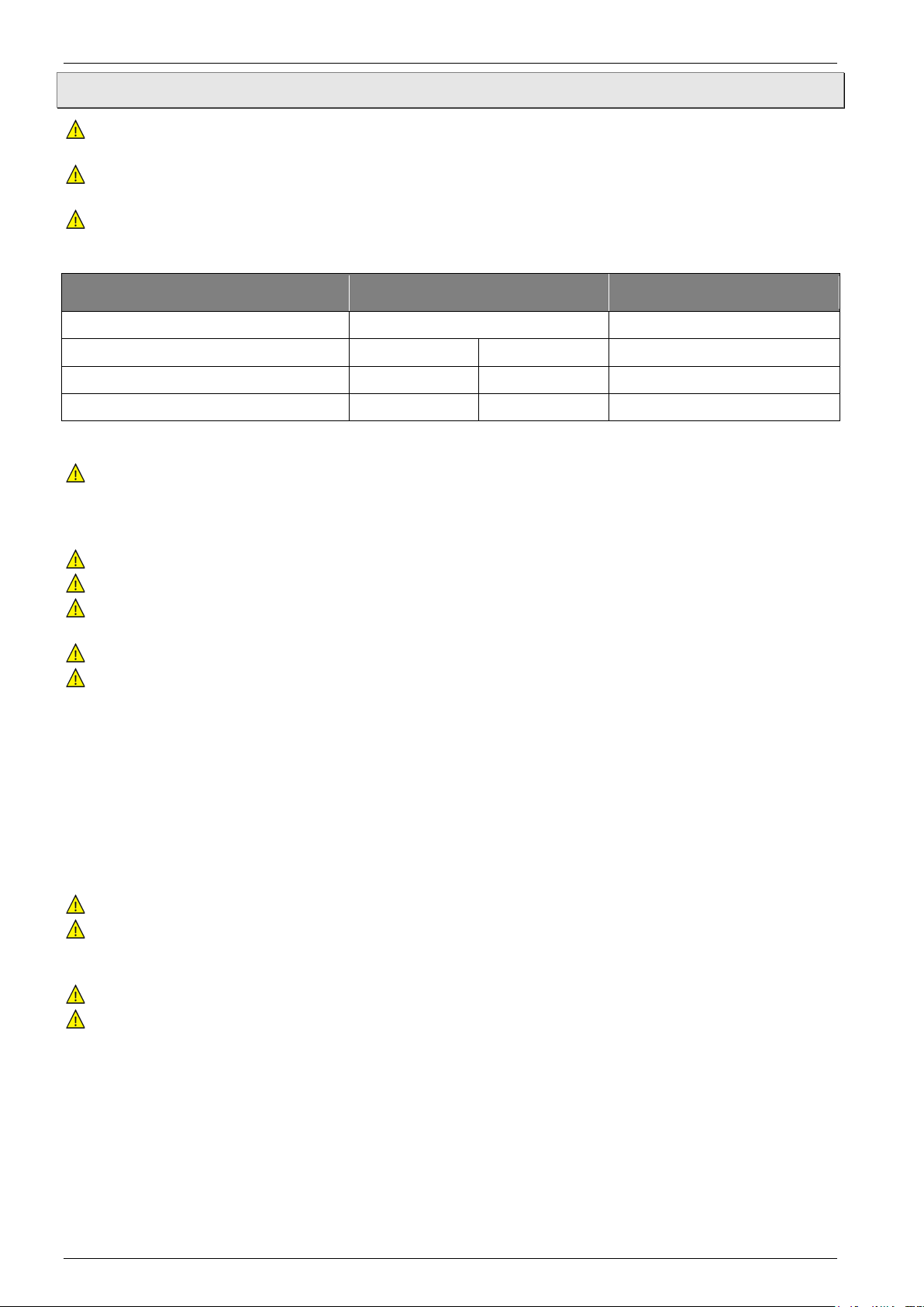
Calibration liquid
Calibration range
Flashpoint
Distilled water
0…95 °C (32…203 °F)
none
Sili cone oil from XI AM ETER®:
PMX-200 SILICONE FLUID 10 CS
-35 °C (-31 °F)
155 °C (311 °F)
165 °C (329 °F)
PMX-200 SILICONE FLUID 50 CS
25 °C (77 °F)
270 °C (518 °F)
280 °C (536 °F)
2.1 Safety instructions for the application of calibration liquids
Before using calibration liquids, read the entire safety data sheet thoroughly. Pay
particular attention to the information on the physical and chemical properties.
Only use calibration liquids that are suitable for the required tem perature range and which
are not flammable.
Always wear safety goggles for the eyes when handling calibration liquids.
We recommend the following calibration liquids for the various temperature ranges:
Water:
Only use distilled water, otherwise excessive limescale and soiling will build up in the
calibrator tank.
Silicone oil:
Use only the silicone oil recommended here.
Always read the safety data sheet supplied with the silicone oil before using it.
Always ensure adequate ventilation when working with silicone oil, since hazardous
substances can be released.
Prevent silicone oil from coming into contact wi th your ey es.
Since silicone oil is hygroscopic, always use the transport cover to close the calibration
bath after use.
IMPORTANT NOTICE! Release of pollutants!
During the heating of the silicone oil at temperatures > 150°C (221 °F) in the presence of
air, small quantities of formaldehyde may be released.
Adequate ventilation is required, so that the permissible MAK value of 0.5 ppm in the 8hour average in the workplace dur i ng normal oper ation is not exceeded.
Mineral oil:
OMEGA ENGINEERING supplies the calibrators only with silicone oil.
Using mineral oil is possible, but must be done on your own responsibility. The danger
and the risk must be borne by the customer and our warranty will be rendered null and
void.
Please follow the safety data sheet of the mineral oil used.
The safety instructions for silicone oil apply analogously for mineral oils as well. The same
also applies to the corresponding sections for silicone oil in this operating manual.
Technical changes reserved - 11 -
Page 12

Construction and function Series TCL
3 Construction and function
3.1 Construction
The calibrator consists of a robust, black-and-red painted steel housing and has a carrying
handle at the top .
The front part of the housing holds the electronics of the TCL, the controller with display
and control elements, as well as the thumb wheel for the magnetic stirrer .
On the front side are the main switch with fuse and power plug connection as well as the
service and data interface .
In the TCL micro bath calibrators, the grille for the exhaust air is located in the side walls
of the housing. In the TCL dry block calibrators, the grille is located in the upper plate of
the housing near the opening of the metal block.
The rear part of the housing holds a heat-insulated calibration block with heating or cooling
elements and an integrated sensor for the reference temperature. In the case of the dry block
calibrator, this is a metal block and in the micro bath calibrator, it is a tank .
In the base, there are grilles for cooling the calibrator. The built-in fans control the inlet air of
the housing and calibration block .
An overview of the most important components of the TCL:
Carrying handle.
Steel housing.
Controller with Display.
Service and data interface.
Main switch with fuse and power plug
socket.
Metal block (Dry block).
Calibrator ventilation:
Exhaust through upper housing grilles.
Tank (Micro bath) with transport cover.
Calibrator ventilation:
Exhaust through lateral housing grilles.
Thumb wheel magnetic stirrer.
Calibrator, bottom view:
Calibrator ventilation
Inlet air for housing cooli ng .
Inlet air for tank / metal block cooling.
- 12 -
Page 13
Series TCL Construction and function
Function
Type
Measuring insert:
Adapter sleeve
Calibration liquid
TCL-165S-D
TCL-650S-D
TCL-M165S-B
TCL-M255S-B
3.2 Functions
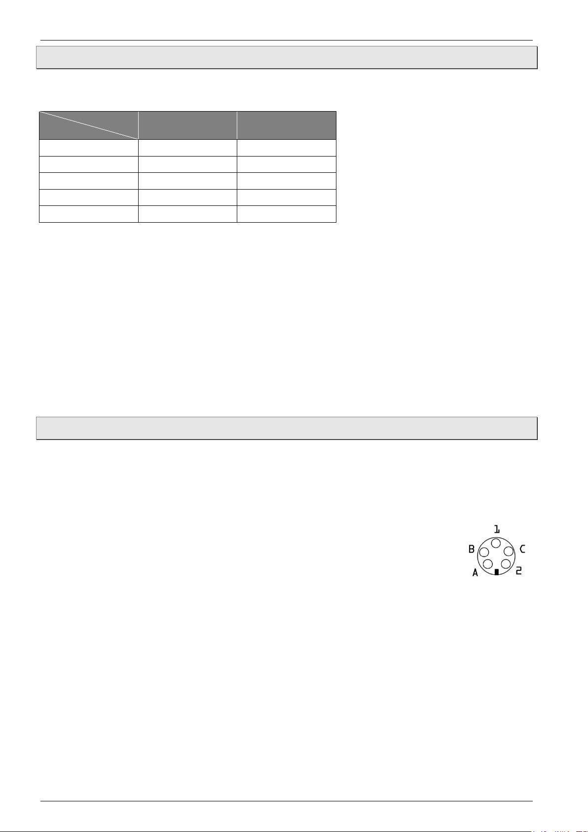
The calibrators can be used with dry block or micro bath functi on an d is determined by the
calibrator type and the measuring insert in use.
Dry block Micro bath
Method of working:
Adapter sleeves or calibration inserts that are suitable for the temperature sensors or
temperature measuring instruments to be tested are inserted in the cali br ator ( § 4.3
"Preparation of the calibrator").
They give the test specimen a secure fit and ensure optimum heat transfer.
Once all the preparations have been carried out, the calibrator can be switched on ( § 4.4).
The calibrator heats or cools the metal block or calibration liquid to the set temperature. As
soon as this temperature has been reached and is stable, the calibration of the test specimen
can be carried out.
Then, the next test point is approached or the testing procedure is ended.
3.3 Data interface
The TCL is equipped with a serial communication interface RS485. It is possible to connect a
PC, a level converter or a network via this interface.
The software used is a MODBUS-RTU protocol, which is used in numerous market-available
monitoring programs. A separate document for the protocol can be supplied on request.
The transfer rate (baud rate) is factory set to 9600 baud. Other transfer rates
are available on request.
The 5-pole socket is provided with two connections, A and B, which have to be
connected to the respective sockets of the PC, the level converter or the
network.
5-pole socket
To enable connection to a PC, the RS 485 signals have to be externally converted into RS
232 or USB signals. Appropriate converters including drivers are optionally available. The PC
records all the operating data and enables the programming of all the calibrator’s
configuration parameters.
The minimum requirements for operation with a USB converter are:
• IBM compatible PC,
• installed operating system Windows 7, Windows 8 or Windows 10,
• a free USB port (USB 1.1 or USB 2.0).
Technical changes reserved - 13 -
Page 14

Construction and function Series TCL
Network configuration
A network configuration allows the
connection of up to 32 calibrator s / micr o
baths to the same networ k.
Certain factory settings have to be carried
out to enable configuration of a network. In
this case, please contact your supplier.
PLEASE NOTE:
If you access the programming via the keypad while communication via a serial interface
is running, the message "buSy" appears on the display.
- 14 -
Page 15
Series TCL Commissioning and operation
4 Commissioning and operation
CAUTION! Risk of injury or material damage!
The calibrator can become very hot during operation. To prevent injury, never leave the
calibrator unsupervised. Moreover, flammable material could get into the calibrator and
cause significant damage to property.
Never leave the calibrator unattended when it is in operation or in the cooling phase.
For safe operation of the calibrators of the TCL series, a proper commissioning procedure is
necessary.
Commissioning includes the installation, the electrical connections, the preparation for the
calibration as well as correct switching on and off of the device.
Further, a visual inspection for dam age is required before use.
The required steps are described in the following sections.
IMPORTANT!
Please also follow the instr uc ti ons for intended us e ( § 1.2), the safety instructions
( § 2) and the information on the ambient conditions ( p. 49).
4.1 Operating conditions
Select a safe installation site for commissioning the calibrator.
Installation site and operating position:
Only suitable for indoor use, do not use outdoors.
Operate only in the vertical position on an even surface. The surface must be stable,
clean, and dry.
If the operation positions do not conform to the above, the structural safety and the
specified properties of the calibrator are not guaranteed.
At higher testing temperatures, please use a sufficiently big, fire-resistant supporting
surface.
Sufficient clearance around the calibrator
On the front side > 1 m, behind and to the sides > 0.5 m. Head clearance and sufficient
clear space above the machine.
Sufficient ventilation must be ensured.
Do not operate in the vicinity of flammable materials.
Do not install in a cupboard or other similar location.
The ventilation openings must not be blocked or covered.
The calibrator must be inst all ed so that it can be switched off at any time.
IMPORTANT! "KILL" switch!
The plug of the power connecting cable serves as a "KILL" switch.
Ensure that the plug is always easily accessible and easy to reach.
In an emergency, pull the plug, so that the calibrator is isolated from the power.
Technical changes reserved - 15 -
Page 16

Commissioning and operation Series TCL
4.2 Electrical connection
The electrical connections are made with the supplied power connecting cable.
DANGER! Risk of death due to electric current!
The TCL is operated at power voltages up to 240 VAC. Contact with the power voltage can
result in serious or fatal injuries.
Switch off the TCL and remove the power connecting cable before you start any work
on live parts.
Check the following points before you connect the calibrator:
Operate the calibrator only with the approved supply voltage ( § 10). Ensure that the
power voltage is the same as that specified on the type plate.
Please follow the local regulations of the energy supplier.
Connect the calibrator only to a properly installed and earthed 3-pole outlet.
Do not use any extension cables or adapter plugs.
IMPORTANT! Power connecting cable!
The power connecting cable may only be replaced by an equivalent cable.
Use only original cables from OMEGA ENGINEERING or approved cables of the
same type with the correct design as replacements ( § 10.1…10.3 "Electrical
characteristics").
Connect TCL:
Connect the power connecting cable with the connector plug of the TCL.
Insert the plug of the power connecting cable in a suitable outlet.
- 16 -
Page 17

Series TCL Commissioning and operation
The function of the calibrator is determined by the measuring insert. The required
4.3 Preparation of the calibrator
The preparations for the test task must be carried out with the calibrator switched off and
cooled to ambient temperature.
CAUTION! Risk of burns!
The calibrator can become very hot when in operation. Touching hot parts can result in
serious burn injuries.
Never touch the metal block, the tank, the adapter sleeve or the test specimen at
temperatures above 35 °C or below 10 °C (95 °F or below 50 °F).
Allow the calibrator to cool before you remove the test specimen, clean the tank,
change the adapter sleeve or the calibration insert or switch off the machine.
IMPORTANT! Empty the tank and clean it!
With micro bath calibrators, the tank must be emptied and cleaned to prevent the adapter
sleeve or the calibration insert from getting stuck.
Empty and clean the tank before you insert another adapter sleeve or calibration
insert.
Measuring inserts:
measuring insert is inserted in the opening of the metal block or the tank.
The measuring insert you can use in which calibrator type is shown in the table in § 3.2.
Technical changes reserved - 17 -
Page 18

Commissioning and operation Series TCL
Type
TCL-165S-D
TCL-650S-D
Dry block
Adapter sleeves and sleeve exchange tool
4.3.1 Dry block calibrator
Adapter sleeves with single or multiple holes are used for the calibration of straight
temperature sensors.
To achieve the specified accuracy of the calibrators ( § 10.1…10.3) the
temperature sensor (test specimen) and the adapter sleeve must be matched to
one another:
• The borehole of the adapter sleeve may be a maximum of 0.5 mm (0.12 in)
larger than the diameter of the test specimen.
• The measurement element of the test specimen must be located in the
homogeneous temperature zone of the adapter sleeve.
Inserting:
The appropriate adapter sleeve is inserted
into the metal block with the aid of the
sleeve exchange tool.
Removing and cleaning:
Let the calibrator cool before you remove
the adapter sleeve.
Pull the adapter sleeve out of the m etal
block with the help of the sleeve exchange
tool.
Clean the adapter sleeve and the metal
block.
This prevents the adapter sleeve from
getting stuck in the metal block.
- 18 -
Page 19
Series TCL Commissioning and operation
Type
TCL-165S-B
TCL-255S-B
Micro bath
4.3.2 Micro bath calibrator
CAUTION! Risk of injury - Wear safety goggles!
Calibration liquid can be ejected when working with the micro bath calibrator.
Always wear safety goggles for the eyes when handling calibration liquids.
The micro bath is used for calibrating sensors with special shapes or dimensions. Direct
contact between the sensor and the calibration liquid ensures excellent heat transfer.
The calibration liquid is poured directly into the tank or into a tub insert ( p. 20).
The micro bath includes the transport cover, the work cover, the sensor cage, the magnetic
stirrer, the draining pump, the magnetic lifter and as an accessory, the tub insert. The
individual components are described below.
Transport cover:
The transport cover serves for secure closing of the micro bath. It prevents spillage of the
calibration liquid during transport.
CAUTION! Safety valve!
The transport cover is equipped with a safety valve, which is activated
once the pressure reaches ~1.5 bar (~21.75 psi). This can result in hot
steam being released.
Always unscrew the transport cover before putting the micro bath into service, in
order to avoid excessive pressure.
Work cover:
The work cover fulfils various tasks during the operation.
• It reduces the evaporation of the calibration liquid to a minimum.
• It reduces the cooling on the surface of the calibration liquid.
• It ensures stable positioning of the test specimens in the micro bath.
The work cover is screwed on to the micro bath and has five openings for
test specimens. The unused openings can be closed with suitable silicone
plugs.
Sensor cage and magnetic stirrer:
The sensor cage protects the magnetic stirrer. It prevents the sensors from
blocking the magnetic stirrer. The function of stirring is ensured by the
sensor cage.
IMPORTANT! Limited Life Part!
The magnetic stirrer is a limited life part.
Replace worn-out magnetic stirrers ( § 8.1 "Maintenance").
The magnetic stirrer ensures a uniform temperature distribution in the
calibration liquid.
Technical changes reserved - 19 -
Page 20

Commissioning and operation Series TCL
Operation of magnetic stirrer:
The speed of the magnetic stirrer is set via the thumb wheel ( Fig.) next
to the controller.
Set the speed to the respective maximum to achieve a thorough mixing.
Turn the thumbwheel upwards to increase the speed.
Turn the thumbwheel downwards to slow down the magnetic stirrer.
Drain syringe and magnetic lifter:
The drain syringe is used for pumping out the calibration liquid from the tank of the micro
bath. The magnetic stirrer is removed with the help of the magnetic lifter.
Both the activities are required before another adapter sleeve or calibration insert is inserted
in the calibrator.
Tub insert (optional / accessory):
We recommend using a tub insert if you
• frequently work with different calibration liquids.
The tub insert is placed into the tank with the help of the sleeve exchange
tool.
Just like the tank, the tub insert can be closed with the associated cover.
Both threaded covers are leak proof, so the calibration liquid can be left in
the tank or the tub insert during transport.
4.3.2.1 Notes on the calibration liquid
Different calibration liquids supply varying calibration results due to their
specific characteristics. Adjustment to the respective calibration liquid has to be carried out
by the manufacturer.
In order to achieve the best possibl e accuracy of a micro bath, it has to be filled with a
suitable calibration liquid ( § 2.1 "Safety instructions for the application of calibration
liquids").
The calibration liquid is poured directly into the tank or a tub insert.
When using water as the calibration liquid:
Only use distilled water, otherwise excessive limescale and soiling will build up in the
tank.
When using silicone oil as the calibration liquid:
Wear safety goggles for the eyes without fail when working with silicone oil!
Use only the silicone oil recommended here.
- 20 -
Page 21

Series TCL Commissioning and operation
max. fill level of the micro bath
Always read the safety data sheet supplied with the silicone oil before using it.
Always ensure adequate ventilation when working with silicone oil, since hazardous
substances can be released.
Spilled or leaked silicone oil results in an extreme danger of slipping. Clean the
affected ranges by suitable means.
Since silicone oil is hygroscopic, alwa ys use the associated transport cover to
close the tank or the tub inse rt after use.
IMPORTANT NOTICE!
Only use clean calibration liquid. Checking temperature sensors and other temperature
detection means can lead to a contam ination of the calibration liquid. This contamination
can lead to smeary gel effect on the bottom of the tank due to the rotation of the
magnetic stirrers.
Clean the tank.
Clean before calibration the sensors.
Exchange the worn magnet stirrer.
Exchange dirty, smeary calibration fluid.
4.3.2.2 Information on filling amounts CAUTION! Risk of incorrect measurement or material damage!
Do not exceed the maximum fill level during operation!
• Above the maximum fill level the heat dissipation is too great, preventing compliance
with the specified tolerances.
• Overflow of the calibration liquid causes contamination and can damage the calibrator.
Ensure that the maximum fill level is not exceeded during operation.
The fill level in the tank or tub insert rises as a result of
• Thermal expansion
Calibration liquids expand to varying degrees as a
result of heating. The increase in fill level depends
on the calibration liquid that is used and the
reference temperature setting.
• Displacement by sensors
The volume displaced by the sensors being
calibrated must be taken into account in the filling
amount.
• Rise due to stirring
The rotation of the magnetic stirrer forms a
whirlpool in the liquid. This raises the fill level at
the wall.
Technical changes reserved - 21 -
Page 22

Commissioning and operation Series TCL
Tank:
The maximum fill level in the tank is d isplayed b y the upper ed ge of the aluminum lining.
The maxim um f il l le vel is ~0.45 liters.
Tub insert:
The maximum fill level with the tub insert is below the fixture for the sleeve exchange tool.
The maxim um f il l le vel is ~0.32 liters.
1
4.3.2.3 Fil ling the micro bath
*
IMPORTANT! Pay atte nti on to § 4.3.2.2 "Information on filling amounts"!
When filling, leave enough room for thermal expansion, displacement by sensors and
level rise due to stirring.
Unscrew the cover of the tank/ tub insert.
Insert the tub insert in the tank using the sleeve exchange tool
(only for tub insert).
Place the magnetic stirrer in the tank / tub insert.
Insert the sensor cage.
Insert the test specimens in the sensor cage.
This accounts for the volume of the sensors to be tested.
Fill the calibration liquid in the tank / tub insert.
Leave sufficient reserve space for an additional rise in
the level.
If necessary, remove the test specimens again.
Screw the work cover onto the tank and insert the
sensors through the work cover into the tank or tub
insert.
1
*
For tubs already filled, some steps are not required.
- 22 -
Page 23

Series TCL Commissioning and operation
4.4 Switching on, cool down and switching off
IMPORTANT!
Follow the instructions and notes of the section ( § 4.1).
For reasons of safety, upon switching on the calibrator, the fan runs at the fastest speed. As
soon as the internal reference has measured a safe block temperature, the fan speed is
adjusted.
Switching on:
Turn on the main switch.
The controller is initialized.
tESt appears in the upper display.
The version number e.g. rL 2.2 appears on the lower display.
Initialization is completed after approx. 5 seconds and the calibration mode ( § 5.2) is
automatically displayed.
The installed heating elements automatically adjust the metal block from the room
temperature to the set temperature set at the controller.
IMPORTANT! Keep in mind after trans por t or st or ag e!
After transport, storage or long periods of non-use, moisture can seep into the heating
elements (magnesium oxide).
For drying, the calibrator must be slowly heated up. During this process, the calibrator
has not yet reached the required insulation voltage for protection class I.
For drying the heating elements, heat the calibrator for at least 15 min to 120 °C
(248 °F).
Cool down the calibrator:
CAUTION! Risk of burns!
The calibrator can become very hot when in operation. Touching hot parts can result in
serious injuries.
Never touch the metal block, the tank, the adapter sleeve or the test specimen at
temperatures above 35 °C or below 10 °C (95 °F or below 50 °F).
In order to cool down the metal block / calibration liquid quickly, set the set
temperature to a low temperature, e.g. room temperature.
The installed fan automatically switches to a higher speed for heating instruments, thus
providing more cooling air. The LED OUT 2 indicates the status of the output for the fan
control. If the LED OUT 2 is lit, the fan is running at high speed. If the LED OUT 2 is not lit,
the fan is running at low speed.
The controller switches the active cooling on for heating / cooling instruments. The LED OUT
2 indicates the status of the output for the active cooling. If the LED OUT 2 is lit, the active
cooling is running. If the LED OUT 2 is not lit, the cooling is not active.
Technical changes reserved - 23 -
Page 24

Commissioning and operation Series TCL
IMPORTANT! Power failure or separation from the power!
If there is a power failure, or if the main switch is turned off, or upon removal of the power
connection ("EMERGENCY STOP"), the built-in fan does not blow any more cooling air.
Sufficient thermal de-coupling between the metal block, the tank and the housing is
nonetheless guaranteed.
Switching off:
CAUTION! Before switching off, pay attention to the block temperature!
The calibrator should first reach a low block temperature before switching off. When
switching off at high temperatures, the calibrator or the test specimen may be damaged.
Switch off the calibrator only when the metal block or tank has reached room
temperature.
Check whether the metal block / tank has cooled down to room temperature.
Switch off the calibrator via the main switch.
Disconnect the calibrator from AC power if no further testing is required.
Unplug the power cord from the wall outlet.
Clean the calibrator after use ( § 8.2).
4.5 Operating modes
During operation, there are three operating modes:
Calibration mode:
This is the normal operating mode in which the calibration of test specimens is carried out.
( § 5.2).
Set point mode:
The set temperatures can be entered in this mode ( § 5.3).
Main menu:
All the settings can be carried out in this mode, e.g. pre-setting the set temperatures or
setting the control parameters. ( § 5.4).
- 24 -
Page 25

Series TCL Operation
• Retur n to previous menu level.
5 Operation
You operate the calibrator via the controller. Depending on the calibrator type, you operate
the calibrator additionally via the thumbwheel of the magnetic stirrer and the switch for the
external reference.
The controller is equipped with two 4-digit LED displays for reference and set temperature as
well as with indicators and control elements which are described in the following section.
5.1 Control elements of the controller
Overview and function of the control elements of the controller:
6 - key
• Inc r easing values to be set.
• Display of current heating capacity in %.
• Selection of individual menu items.
• Retur n to previous menu level.
7 - U key
• Retr ieve saved set temperatures (only for
S version).
1 - Upper display (red)
• Display of current reference temperature.
• Display of individual modes, menu items and
parameter.
2 - Lower display (green)
• Display of set temperature.
• Display of heating / cooling capacity.
• Display of operating duration.
• Display of certain parameters in individual
modes and menu items.
3 - LED SET
• When flashing, it indicates access to
individual menu items and parameters.
4 - P key
• Switching to set point mode.
• Access to menu items and parameters.
• Input conf irmation.
5 - key
• Reducing values to be set.
• Selection of individual menu items.
8 - LED OUT 1
Indicates the status of the output for the
temperature control:
☼ If LED OUT 1 is lit, the calibrator or micro
bath is heating.
If LED OUT 1 is not lit, the calibrator or micro
bath is not heating.
9a - LED OUT 2
a) Heating instrument
Indicates the status of the output for the fan
control:
☼ If LED OUT 2 is lit, the fan is running at high
speed.
If LED OUT 2 is not lit, the fan is running at
low speed.
9b - LED OUT 2
b) Heating and cooling instrument
Indicates the status of the output for the
temperature control:
☼ If LED OUT 2 is lit, the calibrator or micro
bath is cooling.
If LED OUT 2 is not lit, the calibrator or micro
bath is not cooling.
Technical changes reserved - 25 -
Page 26

Operation Series TCL
Display of reference and set
temperature
Temperature control active
The control is done by PID algorithm.
5.2 Calibration (calibration mode)
As soon as the calibrator has been switched on, it switches to the calibration mode after
initialization
5.2.1 Display of reference and set temperature
The current reference temperature is displayed in the upper and the set temperature in the
lower of the display.
Upper display (red):
The red display shows the current temperature of the
metal block or of the calibration liquid.
The red display also shows the selected function
alternately to the temperature if the calibrator has
several functions.
Lower display (green):
The green display shows the current set temperature
chosen by the user.
5.2.2 Display of temperature control The LED OUT 1 indicates the status of the temperature control:
• If LED OUT 1 is lit the temperature control is
active. The heating or cooling is switched on.
• If LED OUT 1 is not lit the heating or cooling is
switched off.
If the LED OUT 1 lights up permanently, the calibrator
is heating up. The temperature control is active so that
the set point is reached as quickly as possible.
If the set temperature has almost been reached,
the LED OUT 1 begins to flash.
The temperature control is activated at
increasingly shorter intervals. Thereby,
unnecessary overheating is prevented.
To ensure good temperature stability, the cycle
time of the controller is set low.
The temperature control is now often ac tivated
but only for a short time.
- 26 -
Page 27

Series TCL Operation
Fan / cooling control active
5.2.3 Display of fan/ cooling control
The LED OUT 2 indicates the status of the output for the fan / cooling control:
a) Heating instrument
The LED OUT 2 indicates the status of the output for
the fan control:
• If the LED OUT 2 is lit the fan is running at high
speed.
• If the LED OUT 2 is not lit the fan is running at
low speed.
b) Heating and cooling instrument
The LED OUT 2 indicates the status of the output for the cooling control:
• If LED OUT 2 is lit the temperature is decreased.
• If LED OUT 2 is not lit the cooling is switched off.
There are two ways to set the set temperature: Either you set a temporary set temperature
( § 5.3) or you save the fixed set temperatures in the main menu ( § 5.4).
5.2.4 Display of heating / cooling capacity and operating duration
In calibration mode, you can check the heating or cooling capacity and the operating duration
of the calibrator. The current values of the calibrator appear on the lower display (green).
Heating or cooling capacity:
Hold down the key.
The current heating and cooling capacity is displayed in % of the maximum capacity.
"H" indicates the heating capacity and "C" indicates the cooling capacity.
Operating duration:
Briefly press the key.
The current number of operating hours of the calibrator is displayed for ~5 s.
5.2.5 ConF menu
In the ConF menu, system parameters of the calibrator can be set. These settings may only
be carried out by authorized OMEGA ENGIN EERING per sonnel .
This menu is protected by a password.
CAUTION! Material damage!
The ConF menu is protected by a password. Unauthorized access can cause damage to
the calibrator.
Do not try to guess the password.
Exit the menu by pressing the P key twice or select another menu item with the or
key.
Technical changes reserved - 27 -
Page 28

Operation Series TCL
Temporary set temperature setting
5.3 Set a temporary set temperature (set point mode)
In this operating mode it is possible to temporarily modify a saved set temperature.
Press the P key shortly.
The currently active set point memory, e.g. SP 2
(set point 2), is displayed by the upper display.
The respective set temperature is displayed by the
lower display.
Press the key to increase the set temperature.
Press the key to decrease the set temperature.
Press the P key again to confirm the new set point.
NOTES:
• Press the and key to raise and lower the value by 0.1 respectively. If the keys
are held pressed for at least one second, the value increases or decreases quickly and
after two seconds even more quickly; this means the desired value can be reached
rapidly.
• If no key is pressed in the set point mode for approx. 15 seconds, the device
automatically returns to the calibration mode.
- 28 -
Page 29

Series TCL Operation
Main menu for simple temperature calibrator or micro bath
5.4 Main menu
All the settings can be carried out in this menu structure.
Press the P key for approx. 5 seconds. The main m enu op ens .
Use the and keys to select the desir ed main m enu (s ee overview).
Press the P key to confirm the selected menu item.
Main menu for calibrator or micro bath
NOTICE!
The TCL version provides certain additional functions, e.g. storage of four different set
temperatures or setting of the control parameters.
Technical changes reserved - 29 -
Page 30

Operation Series TCL
As displayed by the menu structure, it is possible to reach the group and parameter levels
to carry out settings via OPEr.
PLEASE OBSERVE:
Many of the described settings can only be carried out in the TCL version, but this is
displayed in the chapter heading.
Returning to another level
If no key is pressed in the main menu at the group or parameter level for approx. 15
seconds, the device automatically returns to the previous level up to the calibration mode.
You can also return to a previous level by pressing and holding the or key.
- 30 -
Page 31

Series TCL Operation
Menu control OFF
Control OFF setting display
Control OFF setting display
OFF display
5.4.1 Automatic control
For certain tasks it can be advantageous to switch off the control, e.g. to carry out settings at
the calibrator / micro bath.
Switching off automatic control:
Press the P key when in calibration mode for approx. 5 sec., the main menu opens.
The last selected function appears on the upper
display.
LED SET flashes on the lower display.
Press the or key until OFF appears.
Press the P key to confirm.
An alternating display of the current reference
temperature and OFF appears on the upper
display.
The current set tem perature appears on the lower
display
TAKE NOTICE OF:
The controller is now switched off and the reference temperature will continuously
change and adjust to the room temperature without having to be further regulated.
Switching on the automatic control:
The control is switched off if the following display
appears:
An alternating display of the current reference
temperature and OFF appears on the upper display.
The current set tem perature appears on the lower
display.
Switch the control back on by
pressing the P key for appr ox . 5 sec., the m ai n
menu opens.
OFF appears on the upper display.
LED SET flashes on the lower display.
Confirm switching on the controller by pressing the
arrow key until the desired operating mode is
displayed and confirm this with the P key.
PLEASE NOTE:
The control has been reactivated. The calibrator / m icro bath is in calibration mode and
the set temperature is targeted.
Technical changes reserved - 31 -
Page 32

Operation Series TCL
Menu manual control OPLO
Manual control OPLO setting display
Manual control OPLO setting display
OPLO display
5.4.2 Manual control
Switching on the manual control:
It is possible to switch off the automatic control of the calibrator / micro bath and to achieve
the desired temperature via manual control.
Press the P key for approx. 5 sec., the main men u ope ns. The last sel ect e d func ti on
appears on the upper display.
LED SET flashes on the lower display.
Press the or key until OPLO appears.
OPLO appears on the upper display.
LED SET flashes on the lower display.
Press the P key to confirm.
The current reference temperature appears on the
upper display.
The letter H and the currently set output capacity
in % appear on the lower display.
Press the key, to increase the output capaci ty.
Press the key, to decrease the output capacity.
PLEASE NOTE:
Press the and key to raise and lower the value by 0.1% respectively. If the keys are
held pressed for at least one second, the value increases or decreases quickly and after
two seconds even more quickly; this means the desired value can be reached rapidly.
Switching off the manual control:
The manual control is switched on if the following display appears:
The current reference temperature appears on the
upper display.
The letter H and the currently set output capacity
in % appear on the lower display.
Switch the manual control off again by
pressing the P key for appr ox . 5 sec., the m ai n
menu opens.
OPLO appears on the upper display.
LED SET flashes on the lower display.
Confirm switching on the automatic controller by
pressing the arrow key until the desired operating
mode is displayed and confirm this with the P key.
- 32 -
Page 33

Series TCL Operation
′
operator menu OPEr
Group SP
Parameter for the set memory SP1
Set point memory SP3 entry
5.4.3 Stored Set point values Setting and saving fixed set temperatures
In order to save set temperatures in the calibrator / micro bath, the respective set point
memory has to be opened
Press the P key for approx. 5 sec. when in
calibration mode, the main menu opens.
OPEr appears on the upper display.
LED SET flashes on the lower display.
Press the P key again, the group level opens.
OPEr appears on the upper display.
SP appears on the lower display and LED SET
flashes.
Press the P key again, the parameter level opens.
′SP appears on the upper display.
The set point memory SP 1 and LED SET flash on
the lower display.
Use the or key to select one of the four set
point memories SP1, SP2, SP3 and SP4.
Press the P key to open the respective set point
memory.
The selected set point memory, e.g. SP 3 flashes
on the upper display.
The corresponding current set temperature
appears on the lower display.
Press the key to increase the set temperature.
Press the key to decrease the set temperature.
Press the and key to raise and lower the
value by 0.1 respectively. If the keys are held
pressed for at least one second, the value
increases or decreases quickly and after two seconds even more quickly; this means the
desired value can be reached rapidly.
Press the P key to confirm the set temperature.
The set point memory closes and the display returns to the parameter level.
Press and hold the or key to return to the calibration mode.
Technical changes reserved - 33 -
Page 34
Operation Series TCL
Gradient control and temperature profile
Retrieving the set temperatures display
If no key is pressed for approx. 15 seconds, the device automatically returns to a previous
level up to the calibration mode.
Retrieving the saved set temperatures:
The saved set temperatures can be retrieved in calibration mode.
Press the U key for approx. 2 sec., the current set
point memory opens.
The current reference temperature appears on the
upper display.
The set point memory SP… appears on the lower
display for 2 sec. followed by the current set
temperature.
To receive another saved set point SP1, SP2, SP3
or SP4, press the U key again.
The selected temperature value is immediately
adopted and targeted.
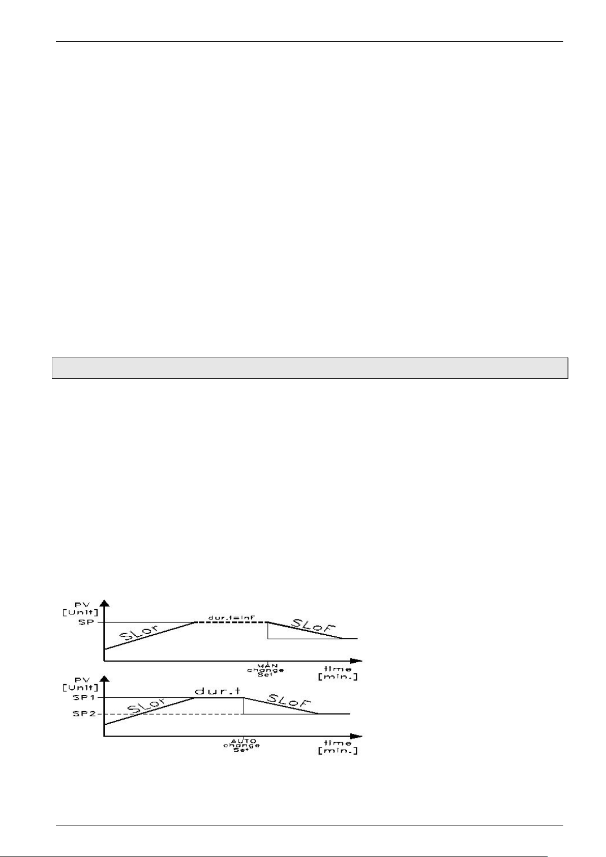
5.4.4 Gradient control / temperature profile
It is possible to carry out a gradient control yourself and thus determine the time in which the
set temperature is reached. The time can be shorter or longer than the time usually required
by the calibrator / micro bath.
When modifying the set temperature or switching on the calibrator / micro bath it is
automatically determined which of the gradients (heating gradient “SLor” or cooling gradient
“SLoF”) is to be used.
Additionally, you can ensure that the calibrator / micro bath switches to the set temperature in
set point memory SP2 as soon as the set temperature in set point memory SP1 has been
achieved and after a programmed duration time “dur.t”; this creates a simple temperature
profile.
After switching on the calibrator / micro bath the temperature profile is automatically carried
out.
- 34 -
Page 35
Series TCL Operation
“SLor”
“SLoF”
Heating/Cooling:
TCL-165S-D
< 7 °C/min (44.6 °F/min)
< 5 °C/min (41 °F/min)
Heating:
< 35 °C/min (95 °F/min)
max. … 300 °C
(572 °F … 212 °F))
< 10 °C/min
(< 41 °F)
(122 °F … 86 °F)
(< 32. 9 °F)
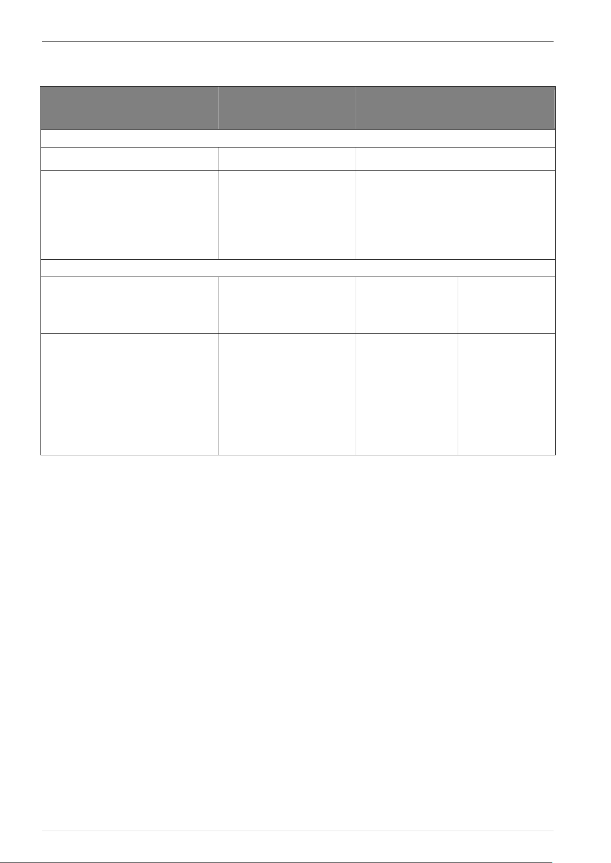
Setting values for “SLor” and “SLoF”
Calibrator type
TCL-M165S-B
- with silicone o il 10CS
- with distille d wat er
TCL-650S-D
TCL-M255S-B
- with silicone o il 50 CS
- with distille d wat er
Heating gradient 1)
< 3 °C/min (37.4 °F/min)
< 5 °C/min (41 °F/min)
< 22 °C/min (71.6 °F)
< 12 °C/min (53.6 °F)
Cooling gradient 2)
< 6 °C/min (42.8 °F/min)
< 4 °C/min (39.2 °F/min)
(max … 572 °F)
300 °C … 100 °C
200 °C … 50 °C
(392 °F … 122 °F)
50 °C … 30 °C
(122 °F … 86 °F)
90 °C … 50 °C
(194 °F … 122 °F)
50 °C … 30 °C
(< 50 °F/min)
< 5 °C/min
< 4 °C/min
(< 39. 2 °F)
< 0,5 °C/min
(< 32. 9 °F)
< 2 °C/min
(< 35. 6 °F)
< 0,5 °C/min
1)
Heating gradient “SLor”:
The heating gradient “SLor” is active if the reference temperature is lower than the set
temperature. Each calibrator type has a max. heating capacity, meaning that only settings
less than this heating capacity are reasonable and extend the time until the set temperature
is achieved.
2)
Cooling gradient “SLoF”:
The cooling gradient “SLor” is active if the reference temperature is higher than the set
temperature. Only settings below the cooling capacity of the calibrator have an effect on the
cooling gradients.
Duration time “dur.t”:
The duration time "dur.t" is active if the set temperature SP1 has been achieved.
Subsequently, the calibrator / micro bath automatically switches to set temperature SP2.
Technical changes reserved - 35 -
Page 36

Operation Series TCL
′
′
′
′
Group ′SP
Group ′rEG
Parameters for heating gradient SLor
ACTIVATE TEMPERATURE PROFILE!
If you have carried out settings for these three settings, the calibrator / micro bath uses
the new values only when modifying the set temperature or switching the calibrator off
and on again.
A further procedure is to switch off the automatic control prior to modifying parameters
and to switch it on again afterwards ( § 5.4.1).
The heating and cooling gradients and the duration time can be set in the parameter level
rEG.
Pressing the P key for approx. 5 sec., the main menu opens.
The last selected function appears on the upper display.
LED SET flashes on the lower display.
Press the or key until OPEr appears.
Press the P key again, the group level opens.
OPEr appears on the upper display.
SP appears on the lower display and LED SET
flashes.
Use the key to select the group ′rEG.
OPEr appears on the upper display.
rEG appears on the lower display and LED SET
flashes.
Press the P key again, the parameter level opens.
rEG appears on the upper display.
SLor flashes on the lower display
- 36 -
Page 37

Series TCL Operation
′
Parameters for heating gradient SLor
Heating gradient entry
5.4.4.1 Setting the heating gradient
The heating gradient "SLor" is active if the reference temperature is lower than the set
temperature.
The setting range extends from 99.99 °C/min (°F/min) up to 0.00 °C/min (°F/min).
PLEASE NOTE:
The function is deactivated if SLor = InF (In no Function) has been set.
You are in the parameter level.
rEG appears on the upper display.
SLor flashes on the lower display.
Press the P key.
SLor flashes on the upper display.
The respective currently set heating gradient
appears on the lower display.
Press the key to increase the heating gradient
SLor.
Press the key to decrease the he ati ng gr adient
SLor
Press the and key to raise and lower the value by 0.1 respectively. If the keys are
held pressed for at least one second, the value increases or decreases quickly and
after two seconds even more quickly; this means the desired value can be reached
rapidly.
Press the P key to confirm the set heating gradient SLor.
The display returns to the parameter level and you can set the other parameters.
Automatic return!
If no key is pressed for approx. 15 seconds, the device automatically returns to a
previous level up to the calibration mode.
Activate temperature profile!
After carrying out the settings, the calibrator uses the new values only when modifying
the set temperature or switching the calibrator / micro bath off and on again.
Technical changes reserved - 37 -
Page 38

Operation Series TCL
′
′
Parameters for heating gradient SLor
Cooling gradient entry
Display of the cooling gradient input
5.4.4.2 Setting the cooling gradient
The cooling gradient "SLoF" is active if the reference temperature is higher than the set
temperature.
The setting range extends from 99.99 °C/min (°F/min) up to 0.00 °C/min (°F/min).
PLEASE NOTE:
The function is deactivated if SLoF = InF (In no Function) has been set.
You are in the parameter level.
rEG appears on the upper display.
SLor flashes on the lower display.
Use the or key to select the parameter SLoF.
rEG appears on the upper display.
SLoF flashes on the lower display
Press the P key.
SLoF flashes on the upper display.
The respective currently set cooling gradient
appears on the lower display.
Press the key to increase the cooling gradient
SLoF.
Press the key to decrease the cooling gradient
SLoF.
Press the and key to raise and lower the value by 0.1 respectively. If the keys are
held pressed for at least one second, the value increases or decreases quickly and after
two seconds even more quickly; this means the desired value can be reached rapidly.
Press the P key to confirm the set cooling gradient SLoF.
The display returns to the parameter level and other parameters can be set.
Automatic return!
If no key is pressed for approx. 15 seconds, the device automatically returns to a
previous level up to the calibration mode.
Activate temperature profile!
After carrying out the settings, the calibrator / micro bath uses the new values only when
modifying the set temperature or switching the calibrator / micro bath off and on again.
- 38 -
Page 39

Series TCL Operation
′
′
Parameters for heating gradient SLor
Parameters for the duration time dur.t
Duration time entry
5.4.4.3 Setting the duration time
The duration time "dur.t" is active if the set temperature SP1 has been achieved.
Subsequently, the calibrator / micro bath automatically switches to set temperature SP2.
The setting range extends from 99:59 [hh:min] to 00:00 [hh:min].
PLEASE NOTE:
The function is deactivated if dur.t = InF (In no Function) has been set.
You are in the parameter level.
rEG appears on the upper display.
SLor flashes on the lower display.
Use the or key to select the parameter dur.t.
rEG appears on the upper display.
SLoF flashes on the lower display
Press the P key.
dur.t flashes on the upper display.
The respective currently set duration time
appears on the lower display.
Press the key to increase the duration time
dur.t.
Press the key to decrease the duration time
dur.t.
Press the and key to raise and lower the
value by 0.1 respectively. If the keys are held pressed for at least one second, the value
increases or decreases quickly and after two seconds even more quickly; this means the
desired value can be reached rapidly.
Press the P key to confirm the set duration time dur.t.
The display returns to the parameter level.
Automatic return!
If no key is pressed for approx. 15 seconds, the device automatically returns to a
previous level up to the calibration mode.
Activate temperature p rofil e!
After carrying out the settings, the calibrator / micro bath uses the new values only when
modifying the set temperature or switching the calibrator / micro bath off and on again.
Technical changes reserved - 39 -
Page 40

Testing process / Calibration Series TCL
6 Testing process / Calibration
CAUTION! Risk of burns!
The calibrator can become very hot when in operation. Touching hot parts can result in
serious injuries.
Never touch the metal block, the tank, the adapter sleeve or the test specimen at
temperatures above 35 °C or below 10 °C (95 °F or below 50 °F).
Allow the calibrator to cool before you remove the test specimen, clean the tank,
change the adapter sleeve or the calibration insert or switch off the machine.
6.1 Testing temperature sensors
A separate temperature measuring instrument connected to the test s peci m en is req uir ed to
test the temperature sensors
By comparing the temperature displayed at the external measuring instrument with the
reference temperature it is possible to assess the status of the test specimen. Remember
that the test specimen requires a short period of time until it absorbs the temperature of the
metal block or liquid bath.
The internal references are set to normal when operating the micro-bath and the dry block
function.
CAUTION! Incorrect results!
It is not possible to calibrate ground thermal elements , bec a use t he heating block is
ground and any measurement would produce incorrect results.
6.2 Testing process
Before the testing process:
Before the start of the testing process, check whether
the instructions regarding the installation site and the operational position have been
complied with ( § 4.1).
the electrical connections have been made correctly ( § 4.2).
the correct measuring insert has been selected for the testing process ( § 4.3).
the test specimen is securely fixed in the calibrator.
the calibrator has sufficient structural stability.
- 40 -
Page 41

Series TCL Testing process / Calibration
Performing testing process:
During the testing process, o ne or mor e test points are approached and the reference
temperature of the calibrator is compared with the measured temperature of the specimen.
Set the set temperature to the value of the first test point.
The temperature control regulates the metal block or the calibration fluid to the
temperature of the test point.
Wait until the temperature has been reached and is sufficiently stable for your checking.
Also note that the temperature of the specimen is stable and transi ent s ar e fini sh ed.
Write down the reference temperature and the temperature of the specimen for your test
protocol.
Set the calibrators gradually to the set values of the further test points and proceed as
described above.
Terminate / cancel testing process:
If the testing process has to be terminated or canceled, the calibrator must be brought in a
safe operational state.
Set the set temperature to a low value e.g. room temperature.
Wait until the calibrator has sufficiently cooled down.
Don’t leave the calibrator unattended at high temperatures.
After the testing process:
Allow the calibrator to cool to room temperature.
Note the instructions in the section "Switching on, cool down and switching off" ( § 4.4).
If necessary drain the tank or tub insert of the micro bath calibrator with the drain syringe.
Clean the calibrator ( § 8.2).
Technical changes reserved - 41 -
Page 42
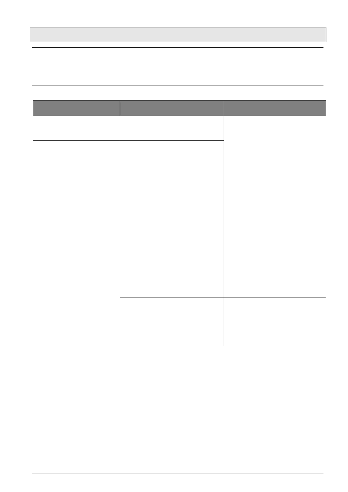
Problems Series TCL
Problem
Possible cause
Remedy
Interruption of the internal
reference sensor is defective.
The controller switches off the
Measured temperature under the
392 °F)
Measured temperature above the
(over range +850 °C / 1562 °F)
Possible fault in the EEPROM
memory of the controller
Press the P key
The fan is defective or blocked
The temperat ure switch is possibly
(servicing required)
Solid state relay is defective or the
circuited or aged
Servicing required
External reference sensor not
properly connected.
Recheck connection and connect
properly.
Cable break or short circuit.
Service call required.
No display
Controller defective
Servicing required
Network connection not
defective
Check the network connection and
7 Problems
CAUTION! Material damage!
The TCL cannot be repaired by the user! In case of a defect, the device must be returned
to the manufacturer for repair .
Never open the TCL and perform any repair yourself.
The following table details what problems you can solve yourself and how to solve them.
- - - -
uuuu
oooo
ErEP
Fan not running
End temperature is not
achieved
Sensor break.
reference sensor or the internal
limit value of the internal reference
sensor (under range -200 °C /
limit value of the internal reference
sensor
heating / cooling element has short
power supply to the heating
cartridge (servicing required).
triggered, switching off the power
supply to the heating cartridge
No function
If you are unable to remedy any particular problem , then immediately disconnect the
calibrator in order to protect it from unintended operation.
Contact your supplier. Please send the device for repair with a brief description of the
problem, the environmental conditions and the length of time the device was operational
before the problem occurred.
- 42 -
established correctly or fuse
fuse
Page 43

Series TCL Problems
7.1 Return shipment to the manufacturer
Contact Omega’s Cust omer Ser vice Department when you have a defective calibrator to
arrange the return of the calibrat or .
Due to legal requirements placed on environmental protection and occupational safety and
health and to maintain the health and safety of our employees, all units returned to OMEGA
ENGINEERING for repair must be free of toxins and hazardous substances. That also
applies to cavities in the devices. If necessary, the customer must neutralize or purge the unit
before return to OMEGA ENGINEERING.
Costs incurred due to inadequate cleaning of the device and possible costs for disposal
and/or personal injuries will be billed to the operating company.
WARNING! Risk of injury due to insufficient cleaning!
The operating company is responsible for all damages and harm of any kind, in particular
physical injuries (e.g. caustic burns or toxic contam inations), decontamination measur es,
disposal etc. that can be attributed to insufficient cleaning of the measuring instrument.
Comply with the instructions below before returning the unit.
The following measures must be taken before you return the unit to Omega for repai r:
Clean the device thoroughly. This is of extreme importance if the medium is hazardous to
health, i.e. caustic, toxic, carcinogenic or radioactive etc.
Remove all residues of the media and pay special attention to sealing grooves and slits.
Attach a note describing the malfunction, state the application field and the
chemical/physical properties of the media.
Please follow the instructions on the procedure for sending returns which are on our
website and please specify a point of contact in case our service department has any
questions.
The customer must confirm that the measures were taken by filling out the declaration of
decontamination. It can be found on our website as a download:
www.omega.com/cservice/wettedproductreturnform.pdf
Technical changes reserved - 43 -
Page 44

Maintenance, cleaning and transport Series TCL
8 Maintenance, cleaning and transport
Before maintenance, cleaning and transport, check whether
the calibrator has cooled sufficiently ( § 4.4 "Cool down").
the calibrator has been switched off and disconnected from the power.
8.1 Maintenance
The TCL itself is maintenance-free and cannot be repaired by the user. In case of a defect,
the device must be returned to the manufacturer for repair.
CAUTION! Material damage!
When opening the device, critical parts or components can be damaged.
Never open the device and perform any repair yourself.
For safe operation of the calibrator, the following checks must be carried out at regular
intervals:
Before use:
Check the calibrator for damage.
For micro bath calibrators, check the filled height of the calibration liquid. When doing so,
note the Information on filling amounts ( § 4.3.2.2).
Annually:
Subject all the parts of the calibrator to a visual inspection for corrosion, wear and
damage.
Have a trained technical person carry out a safety inspection of all the electrical parts.
Recalibration:
The recommended re-calibration interval ( § 8.1.1) is 36 months or after a ma ximum of
500 operating hours.
Calibration liquid:
Calibration liquids get fouled or age with time. This depends to a great extent on the type of
liquid and the usage behavior.
Replace the fouled or aged cali br ation liquid.
Magnetic stirrer:
The magnetic stirrer is a limited life part. The fillet in the middle reduces the friction during the
rotary movement. Once the fillet has worn, the stirring function can no longer be guaranteed
because of the increased friction.
Check the fillet of the magnetic stirrer for wear and replace it in time.
- 44 -
Page 45

Series TCL Maintenance, cleaning and transport
Thermal fuse:
The thermal fuses of the calibrator are located on the front side and are integrated in the
power connection. If there is a power voltage present, but the display is dark and the fan is
not running, you should check the fuses and replace them if required.
Pull the power connection cable from the calibrator.
Open the fuse compartment from the bottom with a flat screwdriver.
Remove the compartment with the fuses.
Check the fuses and replace the faulty fuses.
IMPORTANT! Only use fuses of the same type ( § 10.2…10.3 ).
Always replace both fuses, even if only one is defective.
Fit the fuse compartment back in place and connect the power connecting cable
( § 4.2 “Electrical connection”).
Should the fuses blow repeatedly, there is probably a fault in the calibrator.
In this case, send the calibrator to OMEGA ENGINEERING for repairs ( § 7+§ 7.1).
8.1.1 Recalibration
The calibrator is adjusted and tested with measuring equipment in accordance with
recognized national standards prior to delivery.
The calibrator should, depending on the application situation, be inspected at appropriate
intervals on the basis of ISO 10012. W e recommend you to return the calibrator to OMEGA
ENGINEERING at intervals of max. 36 months or approx. 500 operating hours for
recalibration and readj us tm ent.
Technical changes reserved - 45 -
Page 46

Maintenance, cleaning and transport Series TCL
8.2 Cleaning
External cleaning:
Clean the TCL with a dry or slightly damp lint-free cloth. Do not use sharp objects or
aggressive agents for cl eani ng .
Ensure that your cleaning agent cannot be a source of danger from a reaction with parts of
the machine or the material s insi de it.
If you have any questions regarding compatibility, please contact our customer service.
Venting grilles for inlet air:
The grille openings + in the base of the calibrator must be cleaned
at regular intervals.
The cleaning intervals depend very closely on the air pollution at the
installation site and the daily operation.
Clean the grille openings by vacuuming or brushing off.
Please keep in mind the following instruction regarding the
temperature fuse.
IMPORTANT! Temperature fuse at over -temperature!
An air flow that is too low can result in the temperature fuse getting triggered. The
calibrator is then rendered operationally disabled, and must be sent to OMEGA
ENGINEERING.
Ensure that the grille openings are always clear.
Measuring insert (Adapter sleeves and calibration inserts):
During operation, small quantities of metal dust get created. It can result in the measuring
insert getting stuck in the calibration block.
Pull the measuring insert out of the calibration block with the help of the sleeve exchange
tool.
Clean the measuring insert and the calibration block at regular intervals.
Before a prolonged shutdown of the calibrator, remove the measuring insert from the
calibration block.
Tank (Micro bath calibrator):
Before cleaning, the tank must be drained as much as possible with the draining syringe.
When doing so, follow the corresponding instructions in the safety data sheet of the
calibration liquid used.
Distilled Water:
Remove the sensor cage from the tank.
Remove the magnetic stir r er wi th the help o f the magneti c li ft er.
Dry the tank, the sensor cage, the magnetic stirrer and the draining syringe thoroughly.
- 46 -
Page 47
Series TCL Maintenance, cleaning and transport
Silicone oil:
Remove the sensor cage from the tank.
Remove the magnetic stir r er wi th the help o f the magneti c li ft er
Clean the cage, the magnetic stirrer and the tank with water to which a generous amount
of rinsing liquid has been added.
Remove the cleaning water to the maximum extent possible using the draining syringe.
Dry the tank, the sensor cage, the magnetic stirrer and the draining syringe thoroughly.
8.3 Transport
CAUTION! Risk of burns!
The calibrator can become very hot when in operation. Touching hot parts can result in
serious injuries.
Allow the calibrator to cool down before transport.
Carry the calibrator only at the handle.
Observe the following instructions for a safe transport of the TCL:
The calibrator has to cool down to room temperature.
The calibrator is switched off and is disconnec ted fro m AC power .
All connected sensors and devices have been removed.
The tank of the micro bath calibrator has been closed with the transport cover.
The calibrator must be transpor ted upright.
Avoid bumps and shocks.
Do not let the calibrat or fall nor tip ov er .
Protect the calibrator from damaging environmental influences.
Use our transport case which is available as accessories.
Carry the calibrator only at the handle.
Technical changes reserved - 47 -
Page 48

Decommissioning and di spos al Series TCL
9 Decommissioning and disposal
CAUTION! Risk of injury!
Never remove the device from a measurement set up in operation.
Make sure that the measurement set up is shut down professionally.
Before decommissioning:
Prior to decommissioning, ensure that
the measurement set up is switched off and is in a safe and de-energized state.
the calibrator and the accessories have completely cooled down ( § 4.4 "Switching on,
cool down and switching off").
Decommissioning:
Remove all connected sensors and devi ces .
Switch off the calibrator and disconnect the power plug
Empty the calibrator tank in case there is residual calibration liquid ( § 8.2 "Cleaning").
Disposal calibration liquid:
IMPORTANT! Disposal calibration liquid!
Dispose of the calibration liquid in accordance with the Technical Safety Data Sheet.
Calibrator Disposal:
NO HOUSEHOLD WASTE!
The TCL series calibrator consists of various different materials. It must not be disposed
of with household waste.
Take the TCL to your local recycling plant.
- 48 -
Page 49
Series TCL Technical data
Series
Characteristics
Calibrator
Influence of the operating
32…122 °F) to the accuracy
± 0.02 °C/°C (± 0.036 °F/°F)
Detection speed
130 ms
Control sensor
Internal
Display
Resolution
0.01 °C (°F) (-9.99 … 99.99) or 0.1 °C (°F)
Display unit
°C or °F
Two-line display:
Target temperature
Display for sensor break
- - - -
Electrical characteristics
Degree of protection
IP 20
Block temperature control
via PID-controller
Controller outputs:
100,000 switching cycle
Sensor break behavior
the control is switched off
Excess temperature behavior
temperature fuses interrupt the power supply if there is
excess temperature inside the housing
Ambient conditions
Operating temperature
0…50 °C (32…122 °F)
Transport and storage
temperature
Humidity (RH)
30…95 % (non-condensing environment)
Operating conditions:
Operating position
Standing upright/vertically
10 Technical data
The technical data of customized versions may differ from the data in these instructions.
Please observe the information specified on the type plate.
10.1 Shared characteristics
TCL
temperature (0...50 °C /
Reference temperature
Heater control
Cooler control
Fan control
4-digit, 7-segment LED, 7mm high
red = upper display, green = lower display
voltage output for control of the solid state relay (8 mA/
8 VDC)
voltage output for control of the solid state relay (8 mA/
8 VDC)
relay SPDT (8 A-AC1, 3 A-AC3 / 250 VAC)
-10...60 °C (14…140 °F)
Location • Altitude
Technical changes reserved - 49 -
Interiors • up to 2000 m (6562 ft.)
Page 50
Technical data Series TCL
Series
Characteristics
TLC-165S-D
TLC-650S-D
Temperature range
-35…165 °C (-31…329 °F)
TR …650 °C (1202 °F)
Accuracy
± 0.2 °C (± 0.36 °F)
± 0.4 °C (± 0.72 °F)
Stability
± 0.05 °C (± 0.09 °F)
Display range
-50…165 °C (-58…329 °F)
0…650 °C (32…1202 °F)
Electrical characteristics
Supply voltage
100…240 V
AC,
50/60 Hz
Power consumption
375 W
1000 W
Fuse
6.3 A slow
10.0 A slow
Serial interface:
Serial interface type
RS 485 optoisolated
Communication protoc ol
MODBUS RTU (JBUS)
Serial transfer speed
9600 Baud
Process variables
Test specimen holder
Bore
∅ 28 mm (1.1 in)
Depth
150 mm (5.91 in)
Measurement zone
110…150 mm (4.33…5.91 in)
Housing dimensions
Width
210 mm (8.27 in)
150 mm (5.91 in)
Height
380+50 mm (14.96+1.97 in)
330+70 mm (12.99+2.76 in)
Depth
300 mm (11.81 in)
270 mm (10.63 in)
Weight
~10.0 kg (22.05 lbs.)
~7.5 kg (16.53 lbs.)
Sleeves for smaller ∅
(in 0.5 mm / 0.12 in steps)
1.5…25 mm (0.06…0.94 in)
10.2 Characteristics TLC-650S-D and TLC165S-D
- 50 -
Page 51
Series TCL Technical data
Series
Characteristics
Temperature range
Micro bath(water)
0…100 °C (32…212 °F)
TR …100 °C (212 °F)
Micro bath (silicone oil)
-35…165 °C (-31…329 °F)
TR …255 °C (491 °F)
Accuracy
± 0.1 °C (± 0.18 °F)
± 0.2 °C (± 0.36 °F)
Stability
± 0.05 °C (± 0.09 °F)
Display range
-50…165 °C (-58…329 °F)
0…255 °C (32…491 °F)
Electrical characteristics
Supply voltage
100…240 V
AC,
50/60 Hz
Power consumption
375 W
1000 W
Fuse
6.3 A slow
10.0 A slow
Serial interface
Serial interface type t
RS 485 optoisolated
Communication protoc ol
MODBUS RTU (JBUS)
Serial transfer speed
9600 Baud
Process variables
Test specimen holder
Bore
∅ 60 mm (2.36 in)
Depth
170 mm (6.69 in)
Measurement zone
110…150 mm (4.33…5.91 in)
Housing dimensions
Width
Depth
210 mm (8.27 in)
300 mm (11.81 in)
150 mm (5.91 in)
270 mm (10.63 in)
Weight
~12.5 kg (27.56 lbs.)
~7.5 kg (16.53 lbs.)
Sensor basket working depth
150 mm (5.91 in)
10.3 Characteristics series TCL-M165S-B and TCL-M255S-B
TCL-M165S-B TCL-M255S-B
Height
380+50 mm (14.96+1.97 in)
330+70 mm (12.99+2.76)
10.4 Heating and cooling periods
The following measurement conditions apply to heating and cooling times:
• All times are elapsed times without settling time.
• The measurements were carried out at a room temperature of approx. 23 °C (73.4 °F)
• Without cap, without cover.
• Regulation is based on the internal reference sensor.
Dry block
• Reference sensor Pt100, Ø 6 mm (0.24 in), stainless steel casing
• At full depth the reference sensor is located in the middle of the sleeve.
Micro bath
• Reference sensor Pt100, Ø 6 mm (0.24 in), stainless steel casing.
• The reference sensor is located 5 mm (0.2 in) above the mesh insert in the middle of
the tank.
Technical changes reserved - 51 -
Page 52

Technical data Series TCL
10.4.1 TCL-165S-D (dr y block)
- 52 -
Page 53

Series TCL Technical data
10.4.2 TCL-650S-D (dr y block)
Technical changes reserved - 53 -
Page 54

Technical data Series TCL
10.4.3 TCL-M165S-B (Water and silicone oil)
- 54 -
Page 55

Series TCL Technical data
10.4.4 TCL-M255S-B (Water and silicone oil)
Technical changes reserved - 55 -
Page 56

For your notes
For your notes
- 56 -
Page 57

For your notes
For your notes
Technical changes reserved - 57 -
Page 58

For your notes
For your notes
- 58 -
Page 59

Series TCL
Technical changes reserved - 59 -
Page 60

Series TCL
M-5664/0717
- 60 -
 Loading...