

Page 1
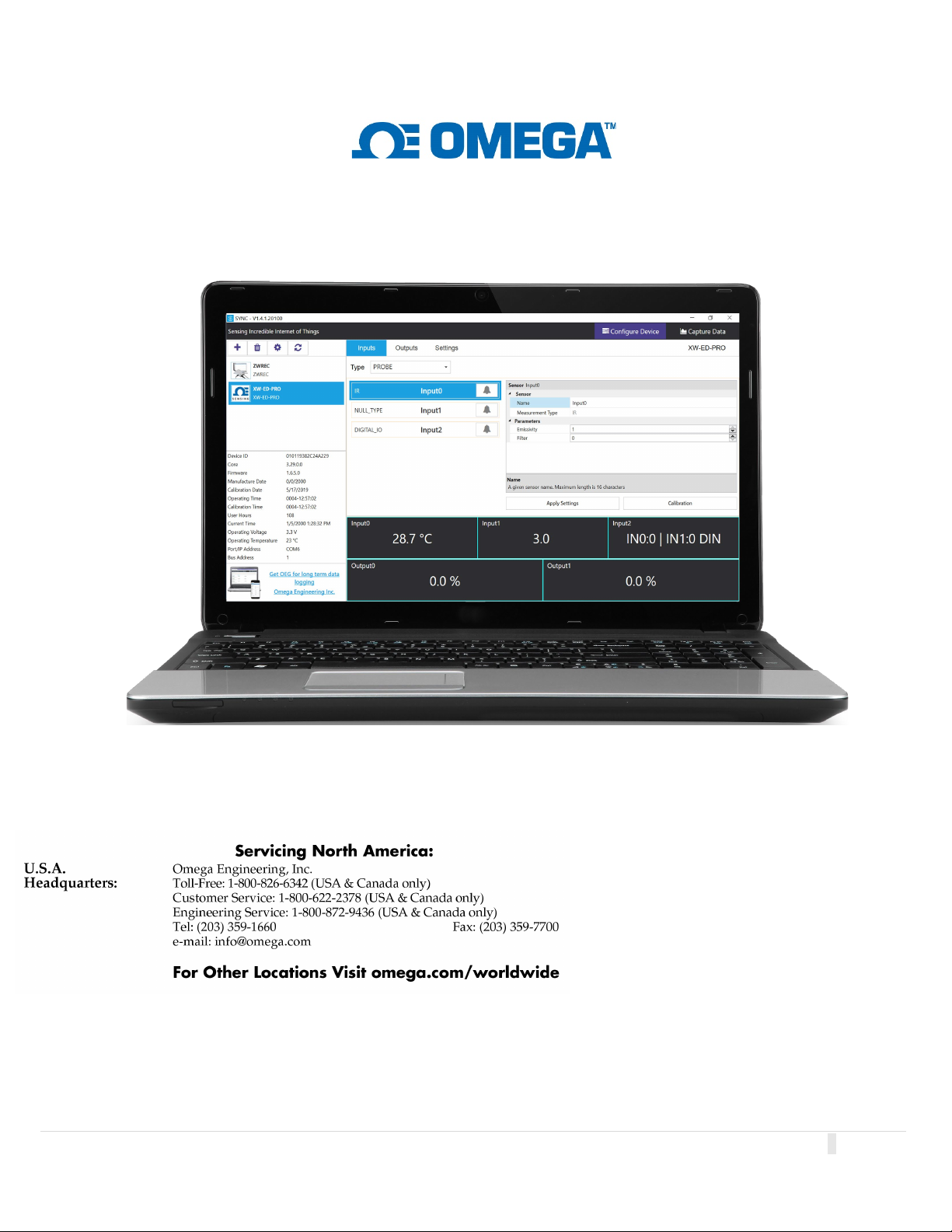
SYNC - Omega Device Configuration Software
M6746-1020
U
ser
’
s Manual
The information contained in this document is believed to
be correct, but OMEGA accepts no liability for any errors it
contains and reserves the right to alter specifications
without notice.
OMEGA’s policy is to make running changes, not model
changes, whenever an improvement is possible. This
affords our customers the latest in technology and
engineering. OMEGA is a registered trademark of OMEGA
ENGINEERING, INC. © Copyright 2017 OMEGA
ENGINEERING, INC. All rights reserved. This document
may not be copied, photocopied, reproduced, translated, or
reduced to any electronic medium or machine-readable
form, in whole or in part, without the prior written consent of
OMEGA ENGINEERING, INC.
1 | Page
Page 2

Table of Contents
TABLE OF CONTENTS ...................................................................................................................................................... 2
1. INTRODUCTION ...................................................................................................................................................... 3
1.1 L
1.2 U
2 INSTALLATION ........................................................................................................................................................ 4
2.1 W
3 CONFIGURE DEVICE INTERFACE ............................................................................................................................... 5
3.1 M
3.2 D
3.3 L
3.4 D
3.5 C
3.6 M
3.7 A
3.8 S
3.9 R
3.10 A
3.11 U
ICENSING ....................................................................................................................................................................... 3
SE SCENARIOS ................................................................................................................................................................ 3
1.2.1 Device Configuration ............................................................................................................................................ 3
1.2.2 Short-Term Data Graphing ................................................................................................................................... 3
INDOWS 7 AND USB INTERFACE INSTALLER ....................................................................................................................... 4
ENU TABS ..................................................................................................................................................................... 5
EVICE AUTO DETECTION .................................................................................................................................................. 5
IST OF DEVICES ............................................................................................................................................................... 5
EVICE ATTRIBUTES .......................................................................................................................................................... 6
ONFIGURATION PANEL ..................................................................................................................................................... 6
EASUREMENT VALUE PANEL ............................................................................................................................................ 6
DD OR DELETE DEVICE BUTTON......................................................................................................................................... 6
YSTEM SETTINGS ............................................................................................................................................................. 6
ECONNECT ..................................................................................................................................................................... 7
UTO SCAN SETTINGS ....................................................................................................................................................... 7
PDATE DEVICES .............................................................................................................................................................. 7
4 CONFIGURING SMART PROBES AND WIRELESS DEVICES .......................................................................................... 8
4.1 I
NPUTS ............................................................................................................................................................................ 8
4.1.1 Setting Alarms ...................................................................................................................................................... 8
4.3 O
UTPUTS ........................................................................................................................................................................ 9
4.3.1 Configuring ON/OFF Control ................................................................................................................................ 9
4.4 D
EVICE SETTINGS .............................................................................................................................................................. 9
5 CONFIGURING PID CONTROLLERS AND PROCESS METERS ....................................................................................... 10
5.1 CN616 ......................................................................................................................................................................... 10
5.2 DP612 ......................................................................................................................................................................... 10
6 LAYER N SMART DEVICE PASSWORD ...................................................................................................................... 11
7 CAPTURE DATA INTERFACE .................................................................................................................................... 12
8 APPENDIX A - EULA ................................................................................................................................................ 13
2 | Page
Page 3

1. Introduction
SYNC by Omega is a device configuration and management software platform for qualifying Omega Smart devices. It allows
users to configure device runtime parameters, view process values, export data, and allows you to efficiently set your
devices to operate under your preferred preferences. SYNC does not support long-term process value storage. We
recommend Omega Enterprise Gateway (OEG) software for long-term data logging and analytics. OEG web client is
platform independent.
SYNC can be installed on Windows
GHz or up; Memory: 4 GB or up; Hard drive: 250 GB or up.
1
.1 Licensing
SYNC is free to all customers who use Omega devices. The software is governed by Omega’s EULA and is also subject to
open source licensing. Please see Appendix A: EULA for more information.
1
.2 Use Scenarios
SYNC is the premier device configurator for Omega Smart products. The use scenarios for the software are outlined
below:
1.2.1 Device Configuration
SYNC provides a universal interface for the efficient configuration of qualifying Omega devices. For further information
regarding a specific Smart Core device, users should refer to the device User’s Manual.
1.2.2 Short-Term Data Graphing
Under certain circumstances, users may want to capture device process values to ensure that the device configuration
is done correctly. SYNC supports short-term data trend viewing and export. For long-term data capture, consider using
Omega Enterprise Gateway.
®
10. The minimum hardware requirements for server installation are: Dual core: CPU 2.4
3 | Page
Page 4
2 Installation
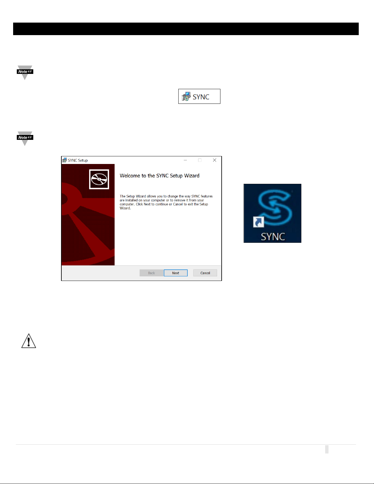
Figure 3
The SYNC zip file contains the installer package for the software. Follow these steps to complete the installation process:
S
tep 1: Unzip and open the SYNC file downloaded from the Omega website.
Note: Included in the installer package are the SYNC Application Files, .msi installer file, User’s Manual, Release
Notes, License and Copyright Notice, and End User License Agreement.
Figure 1
Step 2: Click the SYNC.msi file (Figure 1) and proceed through the setup (Figure 2) to launch SYNC for the first time.
Note: A desktop shortcut icon of SYNC (Figure 3) is created after the installation. This shortcut will launch the
software after the initial installation.
Figure 2
2.1 Windows 7 and USB Interface Installer
For Windows 7 users who will be connecting an IF-001 USB Smart Interface cable or a Platinum USB Interface to
SYNC, an OmegaVCP.inf text file needs to be installed by copying the text file into your C:/Windows/inf/ folder.
The OmegaVCP.inf file is included in your installer package.
Important: I
t is required for Windows 7 users to install the OmegaVCP.inf file to properly connect a USB interface to
SYNC configuration software. Administrator access is required to install this file to your computer.
4 | Page
Page 5
3 Configure Device Interface
3.1 Menu Tabs
SYNC has two menu interfaces:
• Configure Device: Allows you to configure your software adjustable devices.
• Capture Data: Provides short-term data logging features.
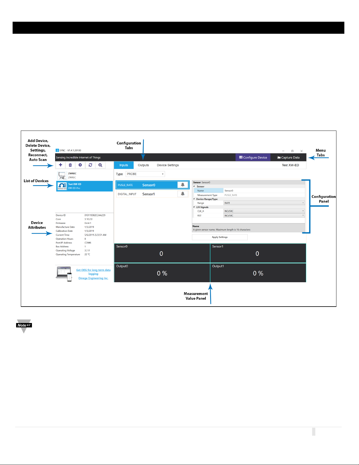
The blank Configure Device interface is the first view you see after SYNC is launched. Once a device is connected, you will
see an interface like the one displayed in Figure 4.
3
.2 Device Auto Detection
Omega Smart devices will be automatically detected once they are plugged in to the computer running the SYNC
software. For instructions on how to connect a specific device to SYNC, please refer to the user documentation associated
with that device.
Figure 4
Note: The Configure Device interface may look differently than the one displayed in Figure 4 depending on the
product that is connected.
3
.3 List of Devices
This section of the interface lists all the devices connected to SYNC. For each connected device, the assigned name and
the product name will be displayed. The device name consists of COM port, device address, and model. Users can switch
between devices in the list to configure or capture data.
ou may right click the device to Rename and Refresh your device. Users may choose to refresh the device this way
Y
should a quick device reboot be necessary.
5 | Page
Page 6
3.4 Device Attributes
The Device Attributes list will appear when you click on a device from the Device List section (Figure 4).
.5 Configuration Panel
3
The configuration of connected devices takes place in the Configuration Panel. The Configuration Panel settings and
parameters will vary depending on the product that is connected. The configuration panel displays the software
adjustable parameters of the Omega device.
3
.6 Measurement Value Panel
The Measurement Value Panel displays the value that the device has been configured to measure. Alarm status and
active zone status are indicated in colors:
• Black: A normal reading is being displayed.
• Red: An alarm condition has been triggered.
• Gray: The reading zone has been disabled.
Note: For more information on how to set alarms on your device, see the section titled Setting Alarms.
3
.7 Add or Delete Device Button
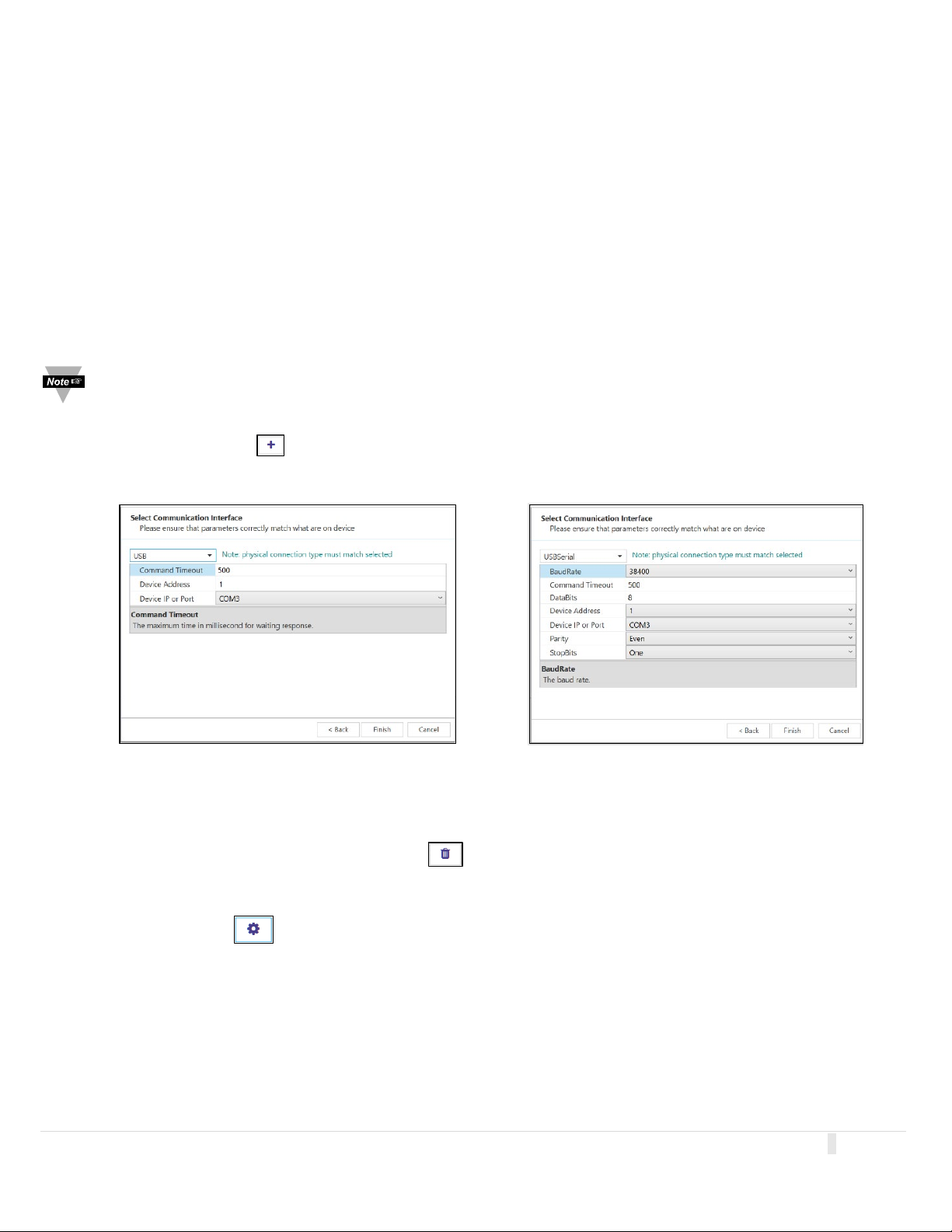
Clicking the Add Device icon (Figure 4) will lead to a wizard that guides you through the process of adding a device to
SYNC.
Figure 5a Figure 5b
Default interface settings are provided in the wizard for USB (Figure 5a) and USB Serial Communication Interface (Figure
5b). Please refer to your device User’s Manual for other communication interface setting options if default settings are
not applicable.
The device can be deleted by clicking the Delete icon (Figure 4).
.8 System Settings
3
The System Settings icon allows the user to customize the Behaviors and Display Units of SYNC.
6 | Page
Page 7
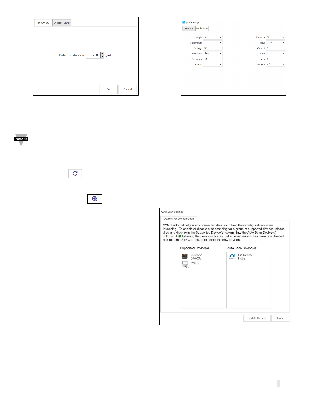
Figure 6a
Figure 6b
The Behaviors tab (Figure 6a) manages the Data Update Rate: the frequency at which the system pulls information from
the device in milliseconds. The Display Units tab (Figure 6b) allows the user to globally customize the units of measure
displayed for various values.
Note: The sensors are permanently set to measure SI units. By changing the Display Units on SYNC, you are only
changing the units displayed on SYNC, not in the sensor itself. Not all configurable global settings that are available
for Smart Probes will be available for PID Controllers and Process Meters.
.9 Reconnect
3
The Reconnect button attempts to connect devices that may not have been auto-detected.
.10 Auto Scan Settings
3
The Auto Scan Settings button allow the user to choose what devices are detected when SYNC auto scans for
connected devices or when the Reconnect button is clicked.
To add a device to the auto scan list, drag the device
category from the Supported Devices Column to the Auto
Scan column. To remove a device from the auto scan list,
drag the device category from the Auto Scan Devices
column to the Supported Devices column. Once you have
finished customizing your settings, click Close.
3
.11 Update Devices
The Update Devices button updates the device library for the listed device categories. The update requires an internet connection and requires SYNC to restart to detect the new devices.
7 | Page
Page 8
4 Configuring Smart Probes and Wireless Devices
Figure 7
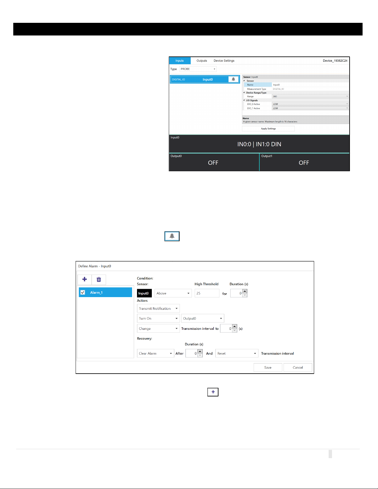
SYNC allows users to configure qualifying Smart Probes and Wireless Devices. To configure these settings, you must have a
Smart Probe or Wireless Device connected to SYNC. Click on the Smart Probe or Wireless Device you would like to
customize from your List of Devices.
Th
e Configuration Tabs allow the user to switch
between the device Inputs, Outputs, and Settings
interface. Refer to the device specific User’s
Manual for the software adjustable inputs,
outputs, and settings available on your device.
• Inputs: Displays configuration options
for device inputs.
• Outputs: Displays configuration options
for device outputs.
• Settings: Displays configuration options
for the device settings and system
functions.
4.1 Inputs
To configure the inputs of your Wireless Device or Smart Probe, begin by navigating to the Inputs Configuration Tab and
select your Input Type from the dropdown. Settings are adjusted on an interface that allows for full configuration of the
device as seen in Figure 7.
4.1.1 Setting Alarms
SYNC allows users to set alarm conditions that notify the user when said conditions are met. The alarm feature is only
available on qualifying products. The alarm icon is located to the right of the input name in the configuration
interface. Clicking the alarm icon will take you to the Define Alarm dialog box as seen in Figure 8.
Figure 8
Once the conditions for your alarm have been set, click the Plus icon to add the alarm to your list of active alarms, and
click Save to finalize.
8 | Page
Page 9
4.3 Outputs
Figure 9
To configure the outputs of your Wireless Device or Smart Probe, begin by navigating to the Outputs Configuration Tab.
Settings are adjusted on an interface that allows for full configuration of the device.
4.3.1 Configuring ON/OFF Control
Note: Only devices that specifically offer digital outputs may configure ON/OFF Control or PWM.
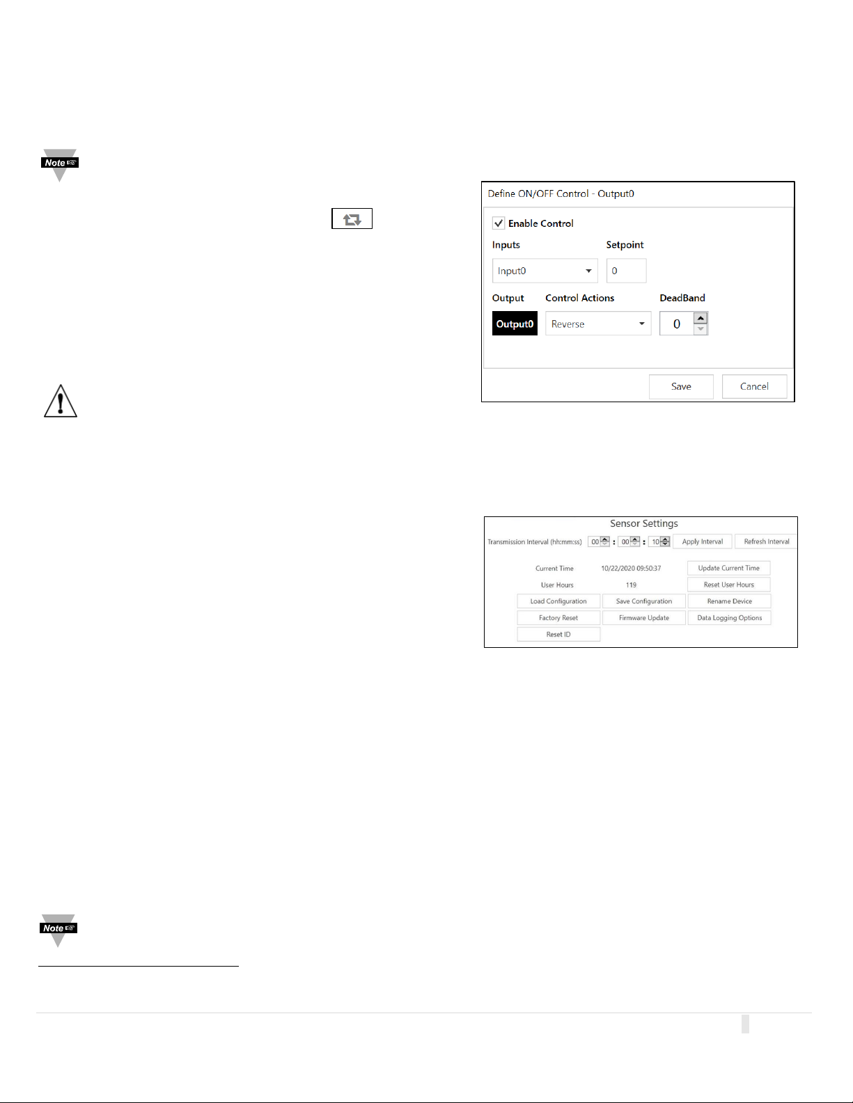
o configure ON/OFF Control on a device, navigate to the
T
Output configuration tab and click on the icon located
to the right of the available outputs. Clicking the icon will open
the Define ON/OFF Control dialog box as seen in Figure 9.
Choose the Input with the active alarm that you would like to
control and set your preferred parameters.
nce the ON/OFF Control parameters have been set, click Save
O
to finalize the settings.
Warning: ON/OFF Control configurations will be erased
if the Input Type is changed. If the Input Type is changed,
ON/OFF Control parameters must be redefined.
.4 Device Settings
4
The system functions may vary depending on the device connected.
• Sensor Setting: Controls the transmission interval of the device.
• Reset User Hours: Resets the user hours to zero as
displayed in the Device Attributes.
• Load Configuration: Allows the user to load a previously
configured .json file to your device via Omega Sync.
• Firmware Update: Allows the user to upload and update
the firmware
• Update Current Time: Syncs the sensor time with th
urrent time displayed on your computer.
c
1
of the device.
e
• Save Configuration: Allows the user to save the current configuration on Omega Sync as a .json file.
• Rename Device: Allows the user to rename the device.
• Factory Reset: Resets the device to its factory settings.
• Set Passwords: Protects the SYNC configuration of your device behind a password. Once a password has been
set, unplug the device and plug it back in to implement the password protection.
• Data Logging Options: When the device data log is full, the user may choose to overwrite the oldest data and
continue logging new data or stop logging new data once the data log memory is full.
• Apply Interval: Sets the transmission interval of your sensing device.
• Refresh Interval: Reads and displays the current transmission interval that may have been changed by sensor
alarms.
Note: Some additional functions not listed here may be device exclusive. For more information on these functions,
refer to your device User’s Manual.
1
The user must already have the updated firmware file saved to their computer.
9 | Page
Page 10
5 Configuring PID Controllers and Process Meters
Figure 12
Figure 10
Figure 11
Important: The following information only applies when connecting qualifying PID Controllers and Process Meters.
Not all configurable global settings that are available for Smart Probes will be available for PID Controllers and
Process Meters.
SY
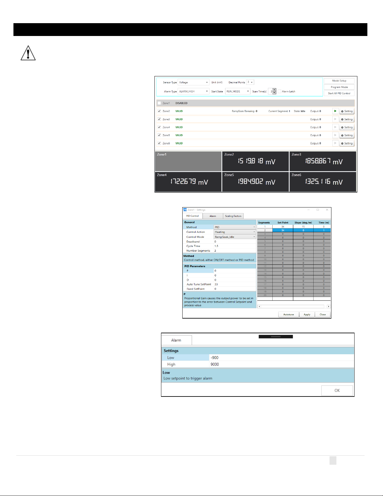
NC allows users to configure qualifying PID
Controllers and Process Meters (CN6xx, DP6xx,
etc.) To configure these settings, you must
have a PID controller or Process Meter
connected to SYNC. Click on the PID Controller
or Process Meter you would like to customize
from your List of Devices.
D Controller / Process Meter settings are
PI
adjusted on an interface that allows for full
configuration as seen in Figure 10.
5.1 C
N616
The Omega CN616 PID Controller allows for the
customization of PID Control, Alarms, and Scaling
Factor. To access these features, click on Settings
for the Zone that you wish to adjust.
k Apply to finalize your changes.
Clic
5.2 DP612
The Omega DP612 PID Controller allows for the
customization of Alarms. To access these features,
click on Settings for the Zone that you wish to
adjust.
k Apply to finalize your changes.
Clic
10 | Page
Page 11
6 Layer N Smart Device Password
Note: It is not required to set a password for your Layer N Devices.
ome Layer N Smart devices, such as Smart Probes and Wireless Smart Interfaces (such as the IF-006), allow users to lock
S
the SYNC configuration features behind a password. When a Smart Probe is attached to an IF-006 with a matching
password, the IF-006 will allow the probe data to be sent to the Layer N cloud when integrated into a Layer N ecosystem.
Caution: Both passwords (Interface and Probe) must match to successfully connect to the Layer N Cloud. Devices
with mismatched passwords will not have cloud access. After 3 failed login attempts, the device will power cycle
before you can retry.
W
hen setting a password, if both passwords do not match, users will have the option to automatically update both
passwords to match. Once a password is set, users will be required to log in to that device before they are able to make
changes to the configuration.
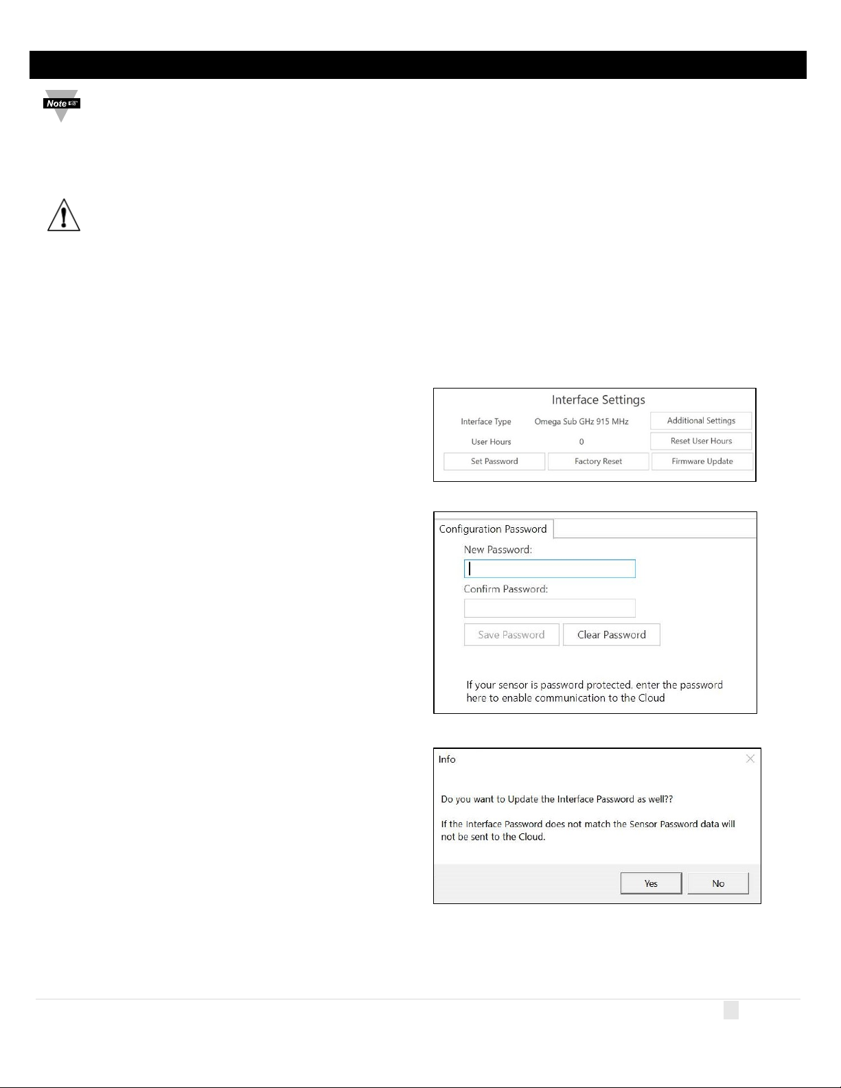
set a password for your Layer N Wireless Smart Interface, navigate to the Device Settings tab of the SYNC interface.
To
tep 1: From the Device Settings Tab, click Set Password
S
under Interface Settings or Sensor Settings,
depending on which you wish to configure first.
S
tep 2: Create a password and click Save Password.
tep 3: If your passwords do not match, you will be able to
S
sync them now.
11 | Page
Page 12
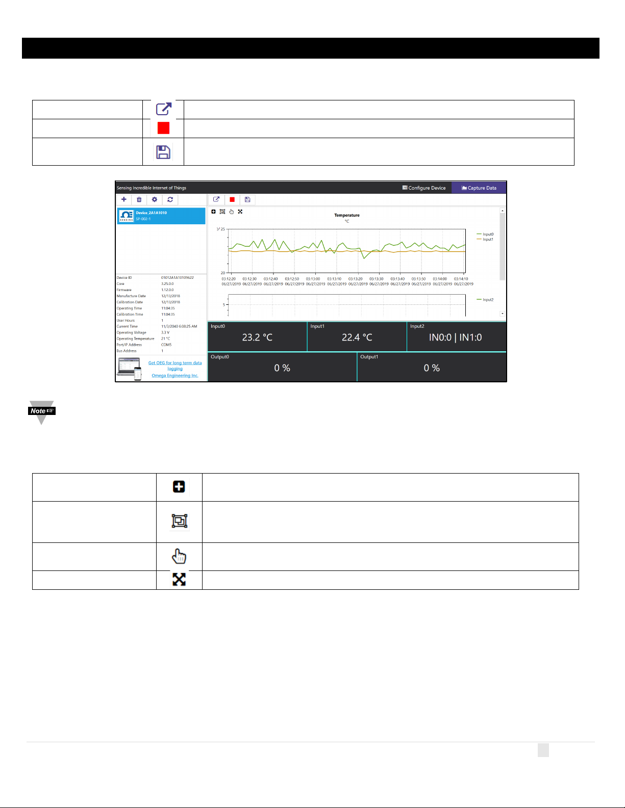
7 Capture Data Interface
Export Data to CSV
File
Allows the user to left click and drag the mouse across the graphed data to
create a rectangle that will be zoomed in on.
Allows the user to zoom in and out of the graphed data using the middle mouse
feature.
Pan by Left Mouse
Button
Allows the user to left click and drag on the graphed data to navigate in the
direction of the mouse.
The Capture Data interface provides a chart that displays real-time data from connected devices. Additionally, the Capture
Data interface contains the following features:
E
xtract Data
Start/Stop Recording Toggles the real-time data display to on/off.
Extracts data from the device data logger.
Gathers the data that has been recorded or extracted and saves it in a CSV file.
Figure 13
Note: Data will be reset if the user switches to the Configure Device interface. SYNC’s Data Capture feature is for
short-term data logging. For long-term data logging, we recommend Omega Enterprise Gateway software.
S
YNC provides four ways to navigate the Capture Data Interface:
Zo
om by Rectangle
Zoom by Middle Mouse
Wheel
Reset Resets the graphed data to the original position.
wheel. This only applies to users have a mouse with the necessary mouse wheel
12 | Page
Page 13

8 Appendix A - EULA
OMEGA ENGINEERING, INC. LICENSE AGREEMENT
*** IMPORTANT ***
READ CAREFULLY BEFORE USING THE SOFTWARE.
BEFORE YOU CHECK IN THE "I accept the terms of this agreement" BOX AT THE BOTTOM OF THIS DIALOG BOX,
CAREFULLY READ THE TERMS AND CONDITIONS OF THIS AGREEMENT. BY CHECK IN THE "I accept the
terms of this agreement" BOX, YOU ARE CONSENTING TO BE BOUND BY AND ARE BECOMING A PARTY TO
THIS AGREEMENT. IF YOU DO NOT AGREE TO ALL OF THE TERMS OF THIS AGREEMENT, UNCHECK IN THE
CHECKBOX HERE AND DO NOT USE THE SOFTWARE.
1
MEGA ENGINEERING, INC. grants to you a non-exclusive, non-sub licensable, non-transferable license to use thi
. O
ersion of the OMEGA ENGINEERING, INC. software. (the "Software").
v
2. O
MEGA ENGINEERING, INC. makes no representations about the suitability of this software or about any content or
information made accessible by the software, for any purpose. The software is provided 'as is' without express or implied
warranties, including warranties of merchantability and fitness for a particular purpose or no infringement. This software is
provided gratuitously and, accordingly, omega engineering, Inc. Shall not be liable under any theory for any damages
suffered by you or any user of the software. Omega engineering, Inc. Will not support this software and will not issue updates
to this software.
s
3. T
itle, ownership rights, and intellectual property rights in and to the Software shall remain in OMEGA ENGINEERING
I
NC. and/or its suppliers. You agree to abide by the copyright law and all other applicable laws of the United Stat
ncluding, but not limited to, export control laws, and the laws of any other applicable jurisdiction. You acknowledge that the
i
Software is source code form remains a confidential trade secret of OMEGA ENGINEERING, INC. and/or its suppliers and
herefore you agree not to modify the Software or attempt to decipher, decompile, disassemble or reverse engineer the
t
Software, except to the extent applicable laws specifically prohibit such restriction.
OM
4.
EGA ENGINEERING, INC. may terminate this License at any time by delivering notice to you and you may terminate
this License at any time by destroying or erasing your copy of the Software. Upon termination of this License, you agree t
stroy or erase the Software. In the event of termination, the following sections of this License will survive: 2, 3, 4, 5, 6 a
de
his License is personal to you and you agree not to assign your rights herein. This License shall be governed by a
7. T
nstrued in accordance with the laws of the State of Delaware, United States of America, and, as to matters affecting
co
copyrights, trademarks and patents, by U.S. federal law. This License sets forth the entire agreement between you a
OM
EGA ENGINEERING, INC.
5. L
icense to the Government: If the Software or Documentation are acquired by or on behalf of a unit or agency of the
United States Government, the Government agrees that such Software or Documentation is "commercial computer software"
or "commercial computer documentation" and that, absent a written agreement to the contrary, the government's rights wit
espect to such Software or Documentation are limited by the terms of this License, pursuant to FAR 12.212(a) and/or
r
DFARS 227.7202-1(a), as applicable.
ou may not use or otherwise export or reexport the Software or any underlying information or technology except in full
6. Y
compliance with all United States and other applicable laws and regulations. In particular, but without limitation, none of the
Software or underlying information or technology may be downloaded or otherwise exported or reexported (i) into (or to a
national or resident of) Cuba, Iran, Iraq, Libya, North Korea, Sudan, or Syria or (ii) to anyone on the US Treasur
epartment's list of Specially Designated Nationals or the US Commerce Department's Denied Persons List. By accepting
D
the terms and conditions of this Agreement, you are agreeing to the foregoing and you are representing and warranting that
you are not located in, under control of, or a national or resident of any such country or on any such list.
es
nd
y
,
o
nd
nd
h
13 | Page
Page 14

7. OMEGA ENGINEERING, INC. or its suppliers shall not be liable for (a) incidental, consequential, special or indirect
da
mages of any sort, whether arising in tort, contract or otherwise, even if omega engineering, Inc. Has been informed of the
possibility of such damages, or (b) for any claim by any other party. This limitation of liability shall not apply to liability fo
eath or personal injury to the extent applicable law prohibits such limitation. Furthermore, some states do not allow th
d
e
xclusion or limitation of incidental or consequential damages, so this limitation and exclusion may not apply to you.
8.HIGH RISK ACTIVITIES. THE Software is not fault-tolerant and is not designed, manufactured or intended for use or
resale as on-line control equipment in hazardous environments requiring fail-safe performance, such as in the operation of
nuclear facilities, aircraft navigation or communication systems, air traffic control, direct life support machines, or weapons
systems, in which the failure of the Software could lead directly to death, personal injury, or severe physical or environmental
damage ("High Risk Activities"). OMEGA ENGINEERING, INC. and its suppliers specifically disclaim any express or
implied warranty of fitness for High Risk Activities.
r
e
14 | Page
 Loading...