

Page 1
Hardware Manual
Re-Order from
omegamation.com
Omegamation
TM
1-888-55-OMEGA
1-888-55-66342
1-888-55-66342
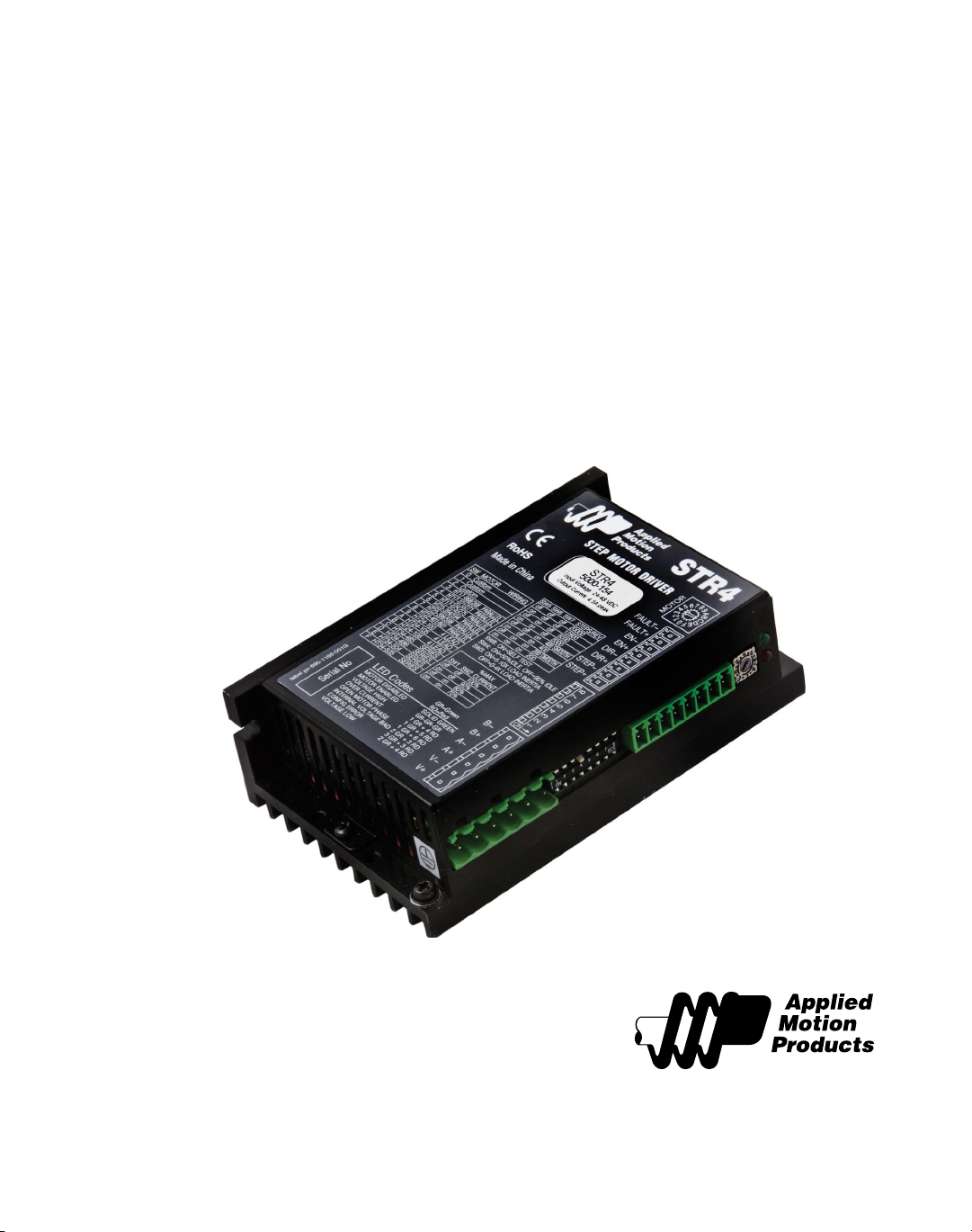
STR4 & STR8
Step Motor Drives
920-0030E
2/3/2010
Page 2
920-0030E
2/3/2010
STR Hardware Manual
Contents
Introduction ...........................................................................................................................................................................................................................................3
Features .................................................................................................................................................................................................................................................... 3
Block Diagram .......................................................................................................................................................................................................................................4
Geing Started ..................................................................................................................................................................................................................................... 5
Mounting the Drive ...........................................................................................................................................................................................................................6
Connecting the Power Supply ....................................................................................................................................................................................................6
Choosing a Power Supply..............................................................................................................................................................................................................8
Volt ag e ............................................................................................................................................................................................................................................8
Current ............................................................................................................................................................................................................................................ 8
Connecting the Motor.................................................................................................................................................................................................................. 11
Four Lead Motor ................................................................................................................................................................................................................... 11
Eight Lead Motor ....................................................................................................................................................................................................................11
Connecting Input Signals............................................................................................................................................................................................................. 12
Connector Pin Diagram ....................................................................................................................................................................................................... 12
Connection Examples: STEP & DIR .............................................................................................................................................................................. 12
Internal Circuit Diagram ...................................................................................................................................................................................................... 12
Connection Examples: EN .................................................................................................................................................................................................. 13
FAULT Output...................................................................................................................................................................................................................................15
Conguring the Drive.................................................................................................................................................................................................................... 16
Step 1: Selecting a Motor .................................................................................................................................................................................................. 16
STR4 Motor Table............................................................................................................................................................................................................. 16
STR8 Motor Table............................................................................................................................................................................................................. 17
Step 2: Seing the Current ...............................................................................................................................................................................................17
Step 3: Seing Idle Current .............................................................................................................................................................................................. 18
Step 4: Load Inertia .............................................................................................................................................................................................................. 19
Step 5: Step Size...................................................................................................................................................................................................................... 19
Step 6: Step Pulse Type ...................................................................................................................................................................................................... 21
Step 7: Step Pulse Noise Filter ......................................................................................................................................................................................... 22
Self Test .................................................................................................................................................................................................................................................22
Reference Materials ........................................................................................................................................................................................................................ 23
Motor Outlines ........................................................................................................................................................................................................................ 23
Torque-Speed Curves .........................................................................................................................................................................................................26
Motor Heating .........................................................................................................................................................................................................................32
Drive Heating ............................................................................................................................................................................................................................ 40
Mechanical Outline ...............................................................................................................................................................................................................41
Technical Specications ...................................................................................................................................................................................................... 42
Mating Connectors and Accessories ...........................................................................................................................................................................43
Alarm Codes .............................................................................................................................................................................................................................44
Connector Diagrams .............................................................................................................................................................................................................44
2
Page 3
920-0030E
STR Hardware Manual
2/3/2010
Introduction
ank you for selecting an Applied Motion Products motor control. We hope our dedication
to performance, quality and economy will make your motion control project successful.
If there’s anything we can do to improve our products or help you use them beer, please call
or fax. We’d like to hear from you. Our phone number is (800) 525-1609, or you can reach us
by fax at (831) 761-6544. You can also email [email protected].
Features
Low cost, digital step motor driver in compact package•
Operates from Step & Direction signals or Step CW & Step CCW ( jumper selectable)•
Enable input•
Fault output•
Optically isolated I/O•
Digital lters prevent position error from electrical noise on command signals•
Jumper selectable: 150 kHz or 2 MHz•
Rotary switch easily selects from many popular motors•
Electronic damping and anti-resonance•
Automatic idle current reduction to reduce heat when motor is not moving•
Switch selectable: 50% or 90% of running current•
Switch selectable step resolution: 200 (full step), 400 (half step), 2000, 5000, 12800 or •
20000 steps/rev
Switch selectable microstep emulation provides smoother, more reliable motion in full and •
half step modes
Automatic self test (switch selectable)•
STR4
Operates from a 24 to 48 volt DC power supply•
Running current up to 4.5 amps per phase•
STR8
Operates from a 24 to 75 volt DC power supply•
Running current up to 7.8 amps per phase•
3
Page 4

920-0030E
AMPLIFIER
24-48 VDC (STR4)
24-75 VDC (STR8)
from external power supply
Status LEDs
Motor Selection
Current
Idle Current
Steps/Rev
Load Inertia
Self Test
STEP
DIR
OUT1
Overcurrent
Sensors
motor
3.3/5/15V
Regulators
Optical
Isolation
Optical
Isolation
Software
Filter
Digital
Filter
Optical
Isolation
EN
DSP
Voltage
Sensors
4
3
2
1
0
F
E
D
C
B
A
9
8
7
6
5
1 2 3 4 5 6 7 8
2/3/2010
Block Diagram
STR Hardware Manual
4
Page 5
920-0030E
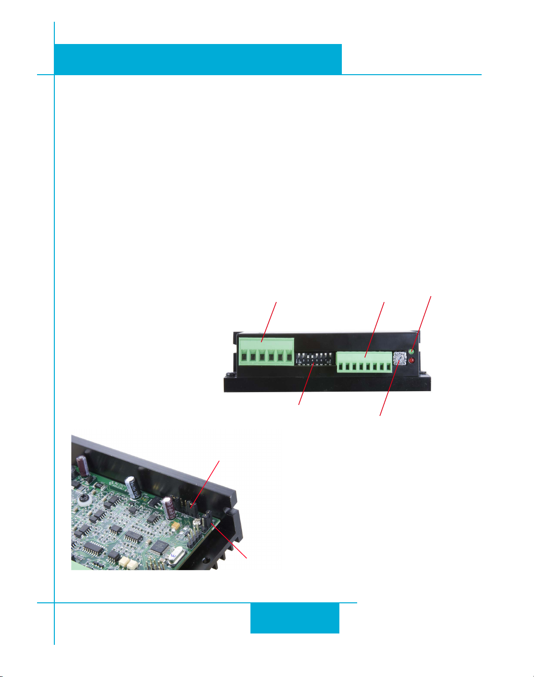
Jumper S4:
Noise Filter Frequency
Jumper S3:
Step & Direction or
Step CW & Step CCW
Remove connectors
and cover to access
jumpers S3 and S4
Motor & Power Supply
Connector
Run Current, Idle Current
Steps/rev, Inertia, Self Test
Input & Output
Signals
Motor Selector
Status LEDs
STR Hardware Manual
2/3/2010
Geing Started
is manual describes the use of two dierent drive models: the STR4 and STR8. ey dier
in maximum output current and maximum power supply voltage. For both models, you’ll need
the following:
• a24to48voltDCpowersupply(75VmaxforSTR8).Pleasereadthesection
Power Supply
• oneofthemotorslistedonthedrivelabel(seesection
for help in choosing the right power supply.
Conguring the Drive
Choosing a
).
• asmallatbladescrewdriverfortighteningtheconnectors.
• asourceofstepsignals,suchasaPLCormotioncontroller.
e connectors and other points of interest are illustrated below. ese are detailed later in
the manual.
5
Page 6
920-0030E
!
2/3/2010
STR Hardware Manual
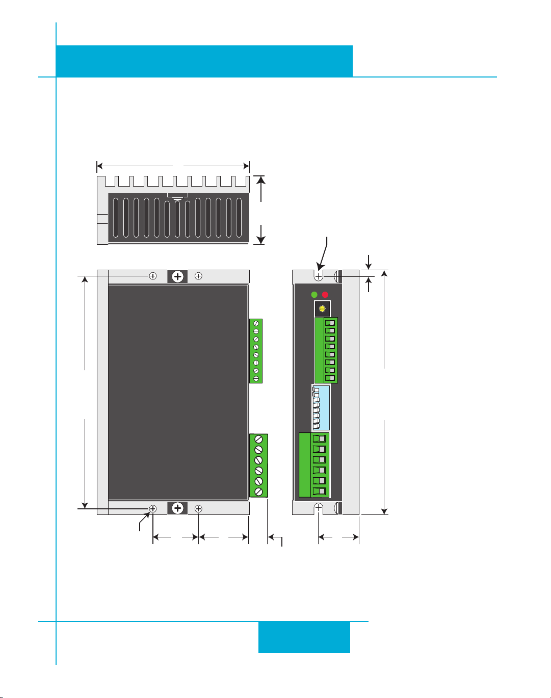
Mounting the Drive
You can mount your drive on the wide or the narrow side of the chassis using #6 screws. If
possible,thedriveshouldbesecurelyfastenedtoasmooth,atmetalsurfacethatwillhelp
conductheatawayfromthechassis.Ifthisisnotpossible,thenforcedairowfromafanmay
be required to prevent the drive from overheating. See page 40 for more details about drive
heating.
• Never use your drive in a space where there is no air ow or where other devices
cause the surrounding air to be more than 50°C.
• Never put the drive where it can get wet or where metal or other electrically conductive particles can get on the circuitry.
• Always provide air ow around the drive. When mounting multiple drives near
each other, maintain at least one half inch of space between drives.
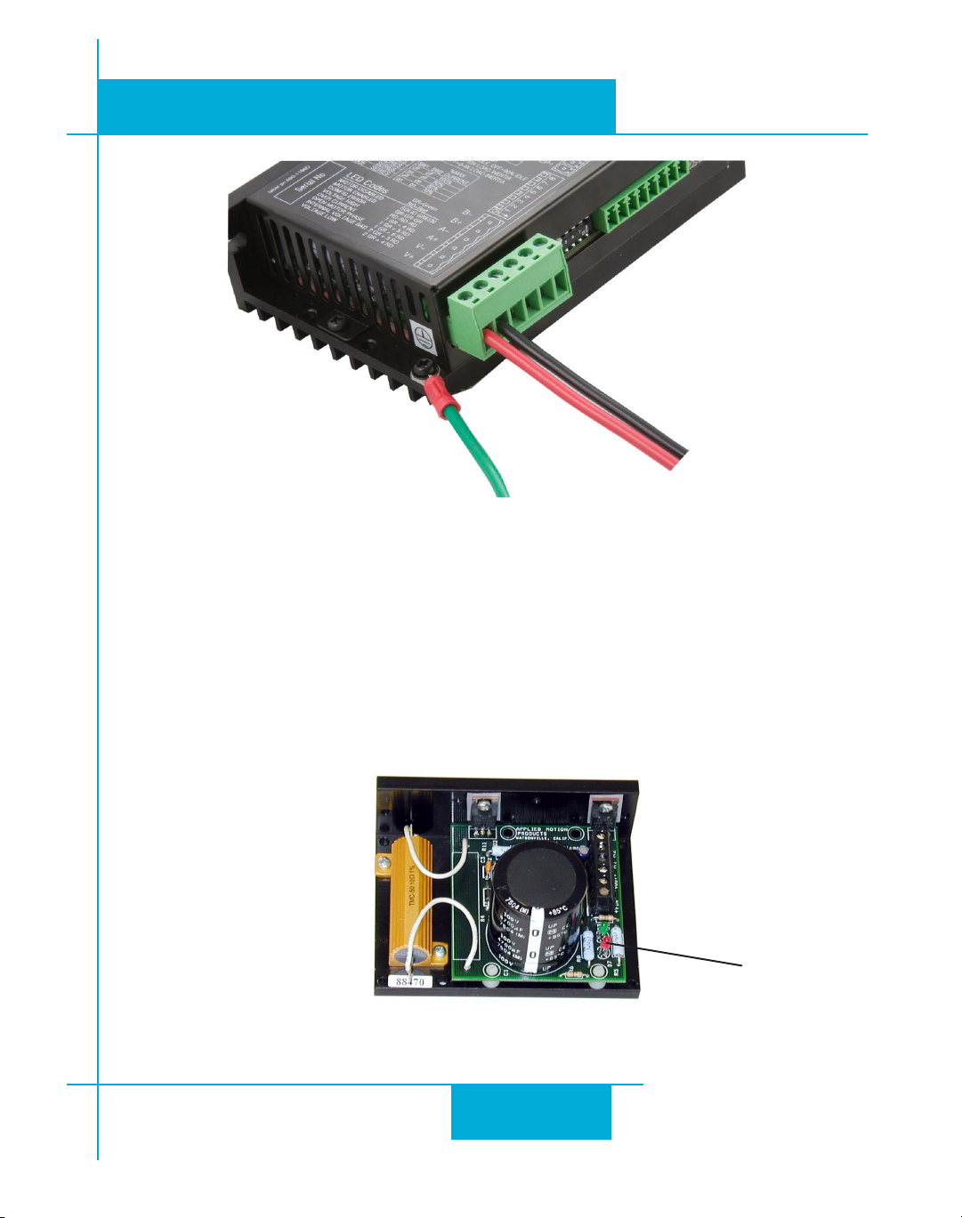
Connecting the Power Supply
If you need information about choosing a power supply, please read the section
Power Supply
Connect the power supply “+” terminal to the connector terminal labeled “V+”. •
Connect power supply “-” to the connector terminal labeled “V-”. •
e green ground screw on the corner of the chassis should be connected to earth ground. •
Use 18 or 20 gauge wire. •
e STR drives contain an internal fuse that connects to the power supply + terminal. is fuse
is not user replaceable. If you want to install a user serviceable fuse in your system install a fast
acting fuse in line with the + power supply lead. Use a 4 amp fuse for the STR4 and a 7 amp
fuse for the STR8.
.
Choosing a
Be careful not to reverse the wires. Reverse connection will destroy your
drive, void your warranty and generally wreck your day.
6
Page 7
920-0030E
STR Hardware Manual
Power Supply and Ground Connections
2/3/2010
Locate fuse in-line with “+” connection
If you plan to use a regulated power supply you may encounter a problem with regeneration.
If you rapidly decelerate a load from a high speed, much of the kinetic energy of that load is
transferred back to the power supply. is can trip the overvoltage protection of a switching
power supply, causing it to shut down. We oer the RC-050 “regeneration clamp” to solve this
problem. If in doubt, buy an RC-050 for your rst installation. If the “regen” LED on the RC-050
neverashes,youdon’tneedtheclamp.
RC-050 Regen Clamp
7
regen LED
Page 8
920-0030E
2/3/2010
STR Hardware Manual
Choosing a Power Supply
When choosing a power supply, there are many things to consider. If you are manufacturing
equipment that will be sold to others, you probably want a supply with all the safety agency
approvals. If size and weight are an issue get a switching supply.
And you must decide what size of power supply (in terms of voltage and current) is needed for
your application.
Applied Motion oers two powers supplies that are excellent matches for the STR4 and STR8
drives: PS150A24 (24V, 6.3A) and PS320A48 (48V, 6.7A).
Voltage
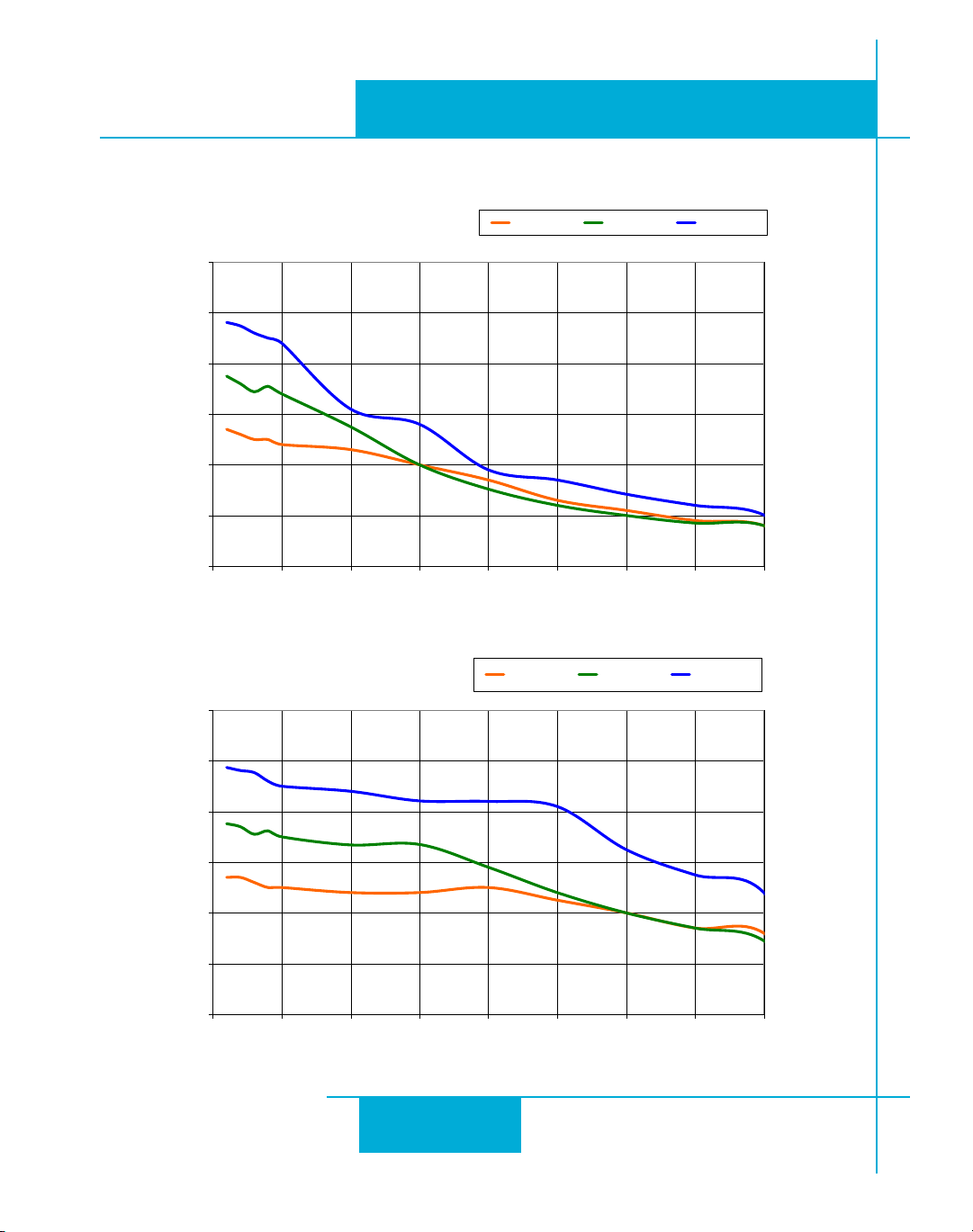
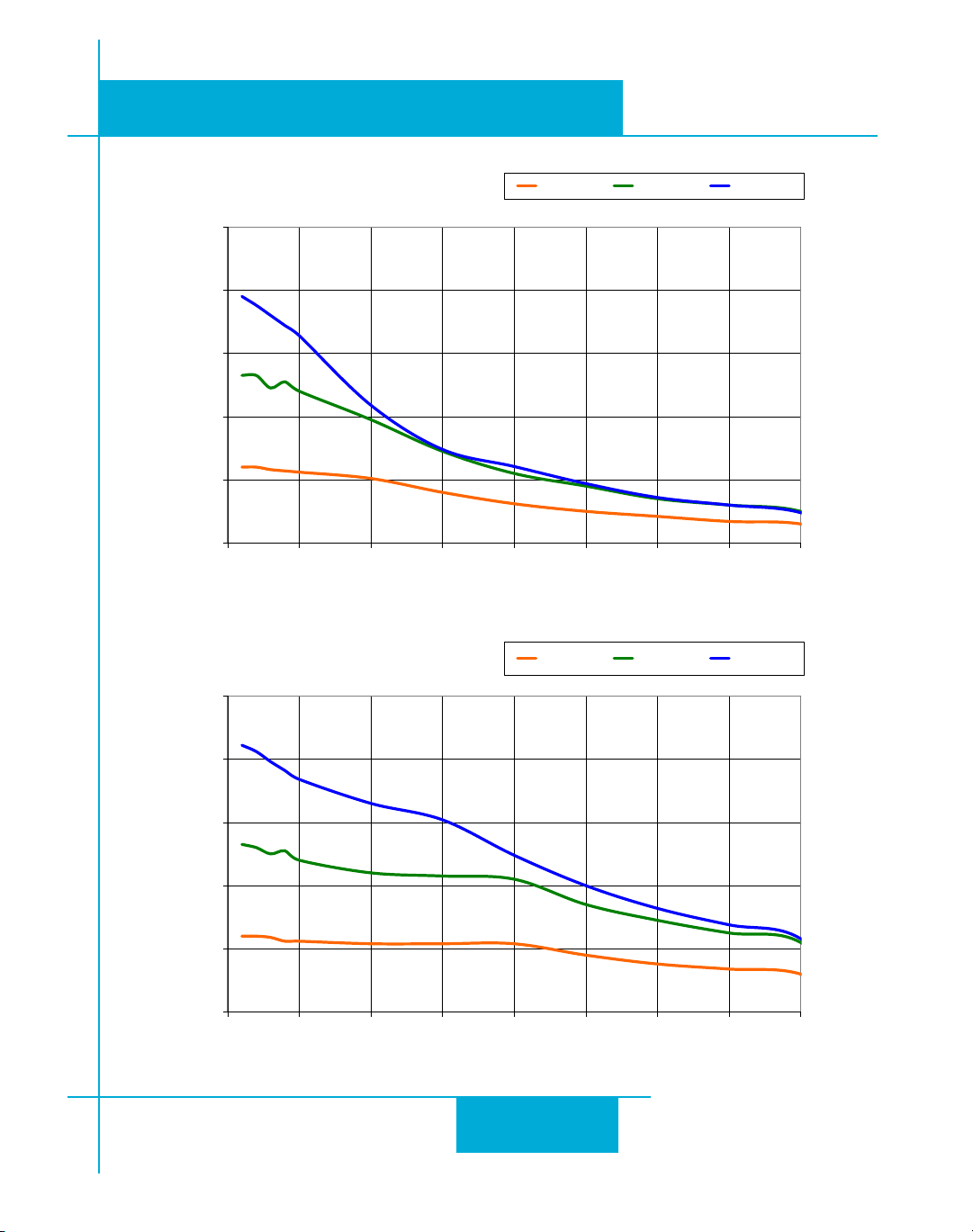
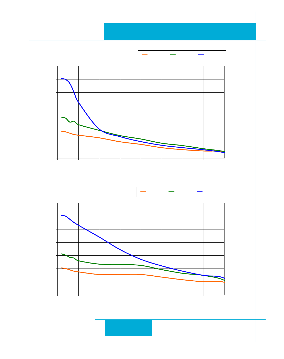
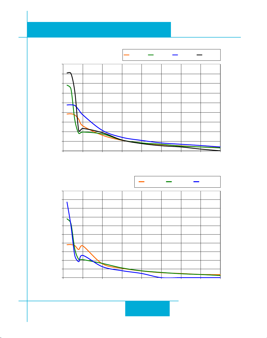
Your motor can provide more torque at higher speeds if a higher power supply voltage is used.
Please consult the speed-torque curves later in this manual for guidance.
If you choose an unregulated power supply, make sure the no load voltage of the supply does
not exceed the drive’s maximum input voltage specication.
Current
e maximum supply current you could ever need is two times the motor current. However,
you will generally need a lot less than that, depending on the motor type, voltage, speed and
load conditions. at’s because the STR uses a switching amplier, converting a high voltage
and low current into lower voltage and higher current. e more the power supply voltage exceeds the motor voltage, the less current you’ll need from the power supply. A motor running
from a 48 volt supply can be expected to draw only half the supply current that it would with a
24 volt supply.
We recommend the following selection procedure:
1. If you plan to use only a few drives, get a power supply with at least twice “per
phase” current rating of the step motor. Example: for a motor that’s rated for 2 A/phase use a 4
A power supply..
2. If you are designing for mass production and must minimize cost, get one power
supply with more than twice the rated current of the motor. Install the motor in the application
and monitor the current coming out of the power supply and into the drive at various motor
loads. is will tell you how much current you really need so you can design in a lower cost
8
Page 9
920-0030E
STR Hardware Manual
power supply.
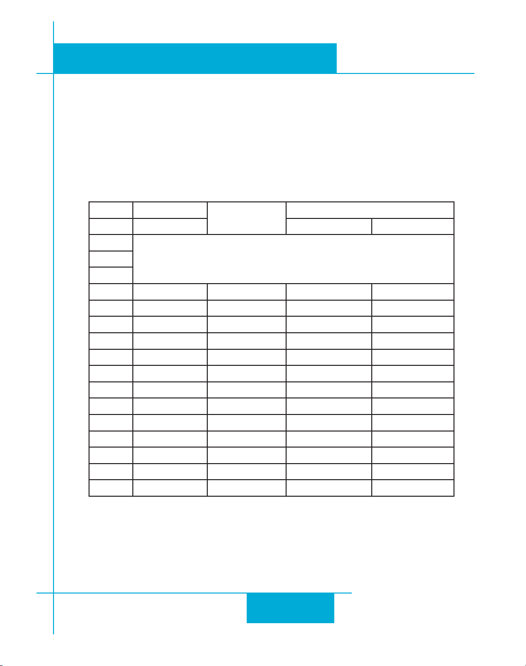
e tables below and on the net page list the maximum current required for each motor at several common power supply voltages. Please consider this information when choosing a power
supply.
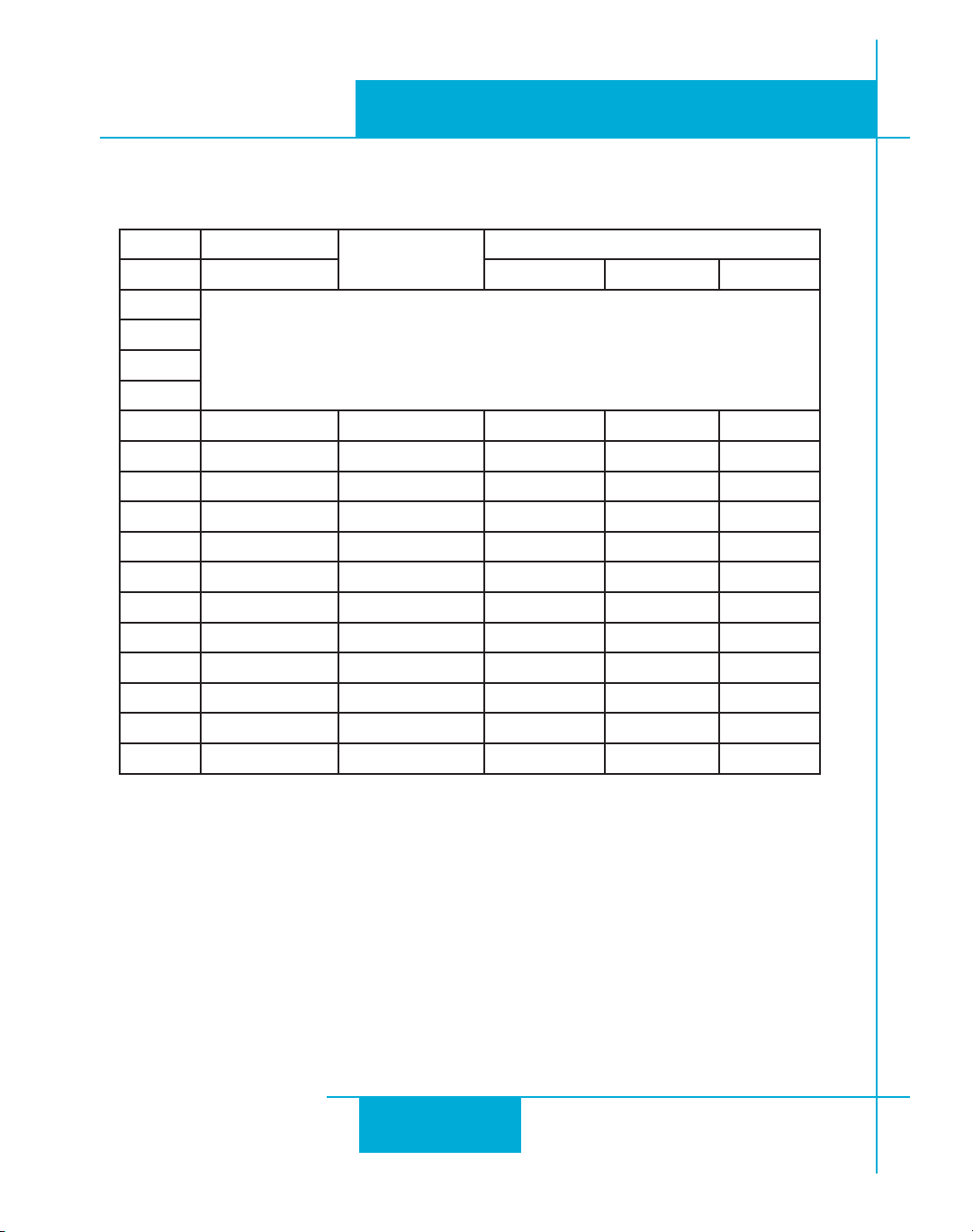
Table 1: STR4 Power Supply Current
All motors connected as indicated, except HT24 which have four leads.
2/3/2010
Motor Current
Switch Motor 24VDC 48VDC
0
2
3 HT17-068/268 1.6 parallel 1.1 1.1
4 HT17-071/271 2.0 parallel 1.1 1.1
5 HT17-075/275 2.0 parallel 1.1 1.1
6 HT23-394/594 3.4 parallel 1.9 2.0
7 HT23-398/598 4.5 parallel 3.2 3.3
8 HT23-401/601 4.5 parallel 3.2 3.4
9 HT24-100 3.36 2.6 2.3
A HT24-105 4.5 5.2 3.2
B HT24-108 4.5 4.3 3.4
C HT34-485 4.5 series 2.6 2.5
D HT34-486 4.5 series 2.4 2.7
E HT34-504 3.816 series 2.1 2.1
F HT34-505 3.816 series 2.4 2.1
(A)
reserved for custom motors1
Max Power Supply Current (A)
9
Page 10
920-0030E
2/3/2010
Table 2: STR8 Power Supply Current
All motors connected in parallel, except HT24 which have four leads.
STR Hardware Manual
Motor Current
Switch Motor 24VDC 48VDC 60VDC
0
1
2
3
4 HT23-394/594 3.4 1.9 2.0 n/a
5 HT23-398/598 5 3.2 3.3 n/a
6 HT23-401/601 5 3.2 3.4 n/a
7 HT24-100 3.36 2.6 2.3 2.0
8 HT24-105 4.8 5.2 3.2 2.7
9 HT24-108 4.8 4.3 3.4 2.9
A HT34-485 8 5.1 5.0 5.0
B HT34-486 8 5.2 4.6 4.4
C HT34-487 8 5.2 5.4 5.3
D HT34-504 7.56 4.8 4.2 4.0
E HT34-505 7.56 4.4 4.2 4.2
F HT34-506 6.72 3.5 3.2 3.3
(A)
reserved for custom motors
Max Power Supply Current (A)
Regeneration
If you plan to use a regulated power supply you may encounter a problem with regeneration.
If you rapidly decelerate a load from a high speed, much of the kinetic energy of that load is
transferred back to the power supply. is can trip the overvoltage protection of a switching
power supply, causing it to shut down. Unregulated power supplies are beer because they
generally do not have overvoltage protection and have large capacitors for storing energy
coming back from the drive. ey are also less expensive. See previous section on
the Power Supply
for details on the RC-050 regeneration clamp.
Connecting
10
Page 11
STR Hardware Manual
!
V+
V
-
A
-
A+
MOTOR
B+
B
-
MOTOR/POWER
CONNECTOR
A+
A–
B+ B–
4
lead
motor
Red
Blue
Yellow
White
4 Leads
Chassis Ground Screw
A+
A–
B+ B–
8
lead
motor
8 Leads Series Connected 8 Leads Parallel Connected
A+
A–
B+
B–
8
lead
motor
Orange
Org/Wht
Blk/Wht
Black
Red
Red/
Wht
Yel/
Wht
Yellow
Orange
Org/
Wht
Blk/Wht
Black
Red
Red/Wht
Yel/
Wht
Yel
low
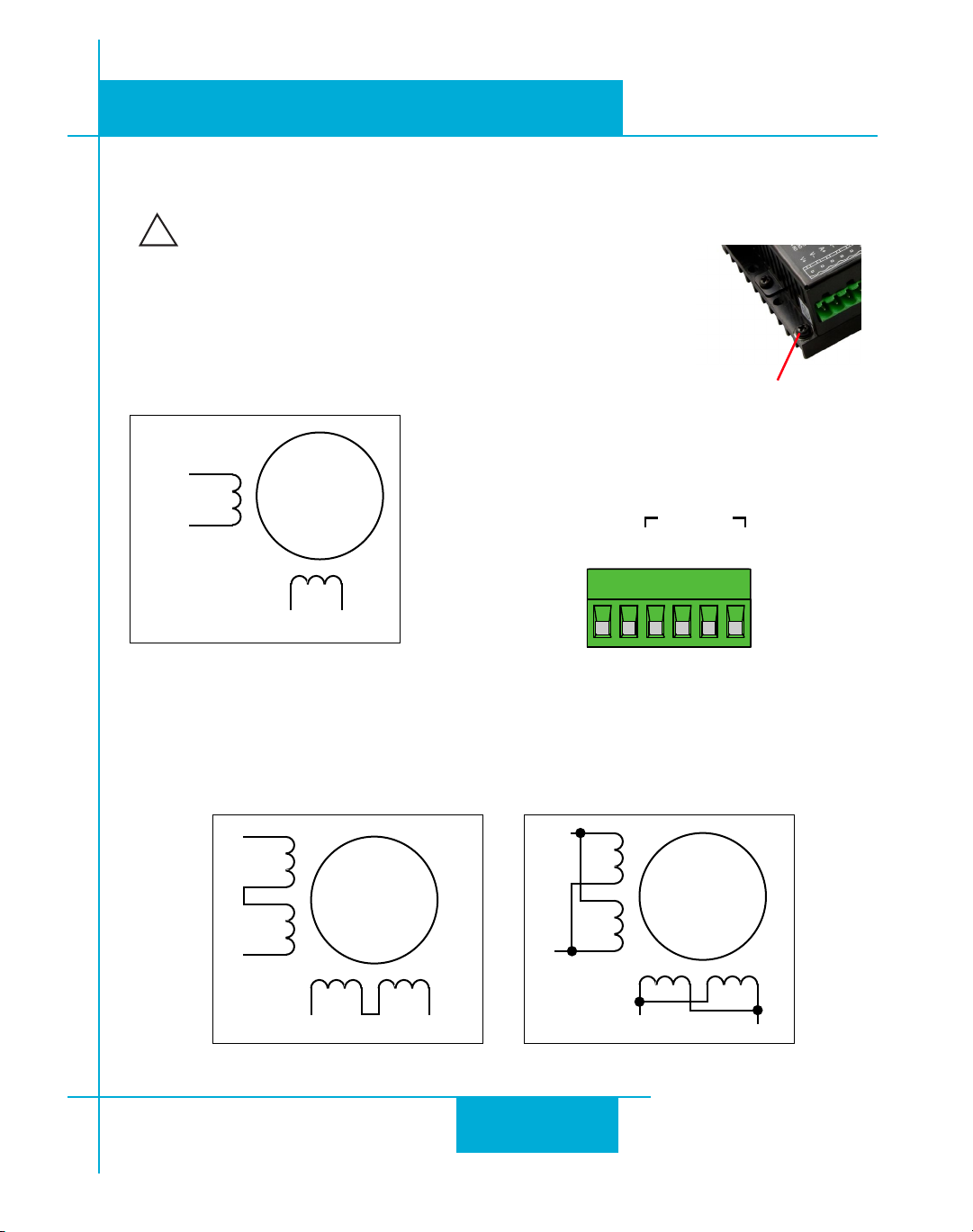
Connecting the Motor
Never connect or disconnect the motor while the power is on.
If the motor has a shield or grounding wire, please connect it to the chassis
ground screw located on the chassis near the motor-power connector.
Four Lead Motor
ese motors can only be connected one way. Please follow the sketch
below.
920-0030E
2/3/2010
Eight Lead Motor
ese motors can be connected in series or parallel. A series connected motor needs less current than one that is connected in parallel but it will not be able to run as fast. Once you have
determined which way you want to connect your motor to the drive, please follow the wiring
diagrams below.
11
Page 12
920-0030E
STEP+
STEP
–
DIR–
EN+
EN
–
FAULT+
FAULT–
DIR+
inside drive
220 pF
STEP+
STEP-
220 pF
DIR+
DIR-
220 pF
EN+
EN-
FAULT+
FAULT-
STR
COM
DIR-
DIR DIR+
STEP-
STEP STEP+
Indexer
with
Sourcing
Outputs
2/3/2010
STR Hardware Manual
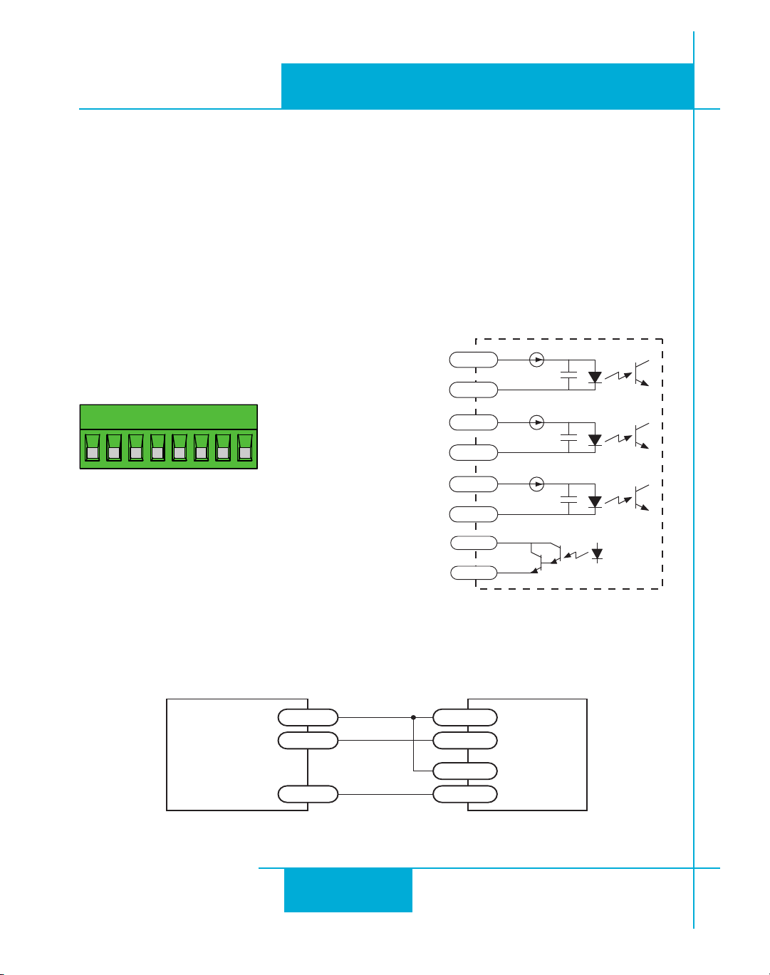
Connecting Input Signals
e STR drives have three inputs:
•STEP:ahighspeeddigitalinputforsteppulsecommands,5-24voltlogic
•DIR:ahighspeeddigitalinputforthedirectionsignal,5-24voltlogic
•EN:a5-24Vinputforcommandingtheremovalofpowerfromthemotor
Note: STEP and DIR inputs can be converted to STEP CW and STEP CCW by moving the internal jumper S3. See Page 5.
Connector Pin Diagram Internal Circuit Diagram
Connection Examples: STEP & DIR
Connecting to indexer with Sourcing Outputs
12
Page 13
STR Hardware Manual
STR
+V OUT
DIR+
DIR DIR-
STEP+
STEP STEP-
Indexer
with
Sinking
Outputs
STR
DIR+
DIR+
DIR- DIR-
STEP+
STEP-
STEP+
STEP-
Indexer
with
Differential
Outputs
STR
switch or relay
(closed=logic low)
EN-
EN+
5-24
VDC
Power
Supply
-
+
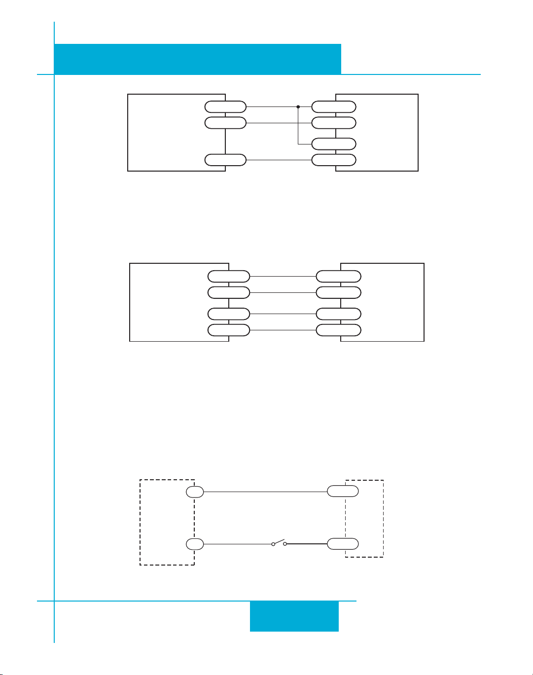
Connecting to Indexer with Sinking Outputs
920-0030E
2/3/2010
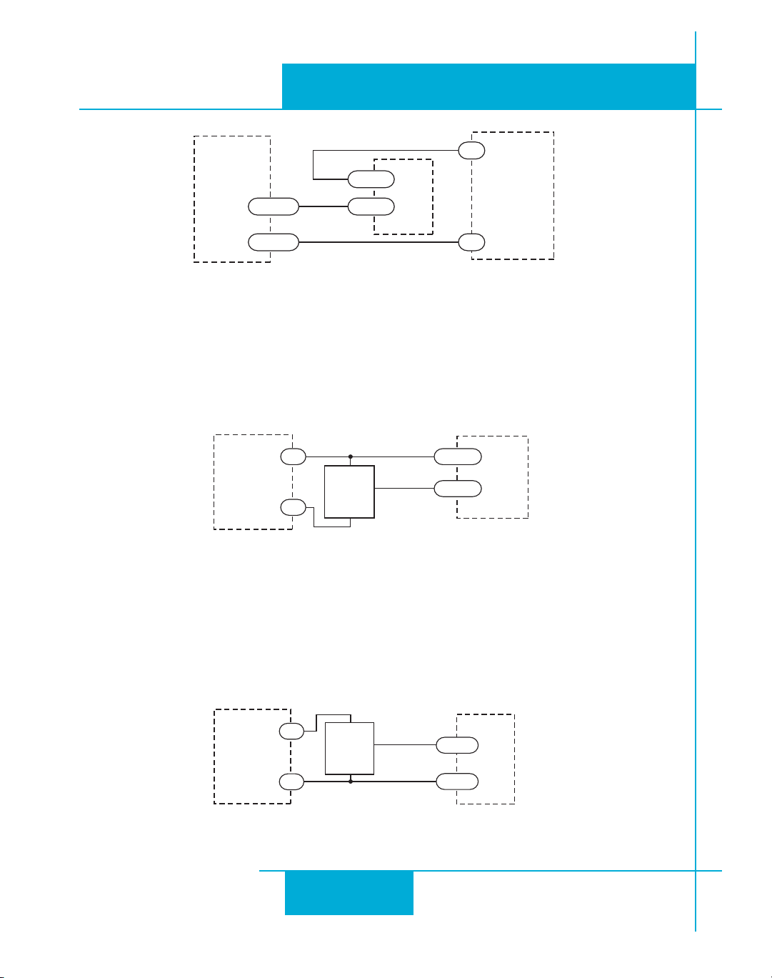
Connection Examples: EN
Connecting to Indexer with Dierential Outputs
(Many High Speed Indexers have Dierential Outputs)
Connecting an Input to a Switch or Relay
13
Page 14
920-0030E
STR
EN-
EN+
Si drive
OUT+
OUT–
5-24
VDC
Power
Supply
-
+
STR
NPN
Proximity
Sensor
EN-
EN+
output
+
–
5-24
VDC
Power
Supply
-
+
STR
PNP
Proximity
Sensor
EN+
output
+
–
EN-
5-24
VDC
Power
Supply
-
+
2/3/2010
STR Hardware Manual
Connecting another drive to EN
(When output closes, input closes)
Connecting an NPN Type Proximity Sensor to an input
(When prox sensor activates, input closes)
Connecting a PNP Type Proximity Sensor to an input
(When prox sensor activates, input closes)
14
Page 15
920-0030E
STR
5-24 VDC
Power Supply
+ –
Load
FAULT-
FAULT+
!
STR
5-24 VDC
Power Supply
+ –
Load
FAULT-
FAULT+
STR
FAULT-
FAULT+
1N4935 suppression diode
5-24 VDC
Power Supply
+ –
relay
FAULT+
FAULT-
STR Hardware Manual
2/3/2010
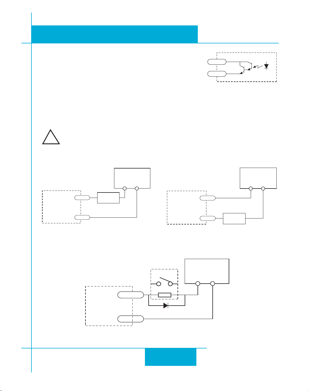
FAULT Output
e STR drives feature a digital FAULT output. is output closes
to signal a fault condition.
is output can be used to drive LEDs, relays and the inputs of
other electronic devices like PLCs. e “+” (collector) and “-” (emier) terminals of the output
transistor are available at the connector. is allows you to congure the output for current
sourcing or sinking.
Diagrams of each type of connection follow.
Do not connect the output to more than 30VDC.
e current through the output terminal must not exceed 80 mA.
Sinking Output
Sourcing Output
Driving a Relay
15
Page 16
920-0030E
2/3/2010
STR Hardware Manual
Conguring the Drive
Step 1: Selecting a Motor
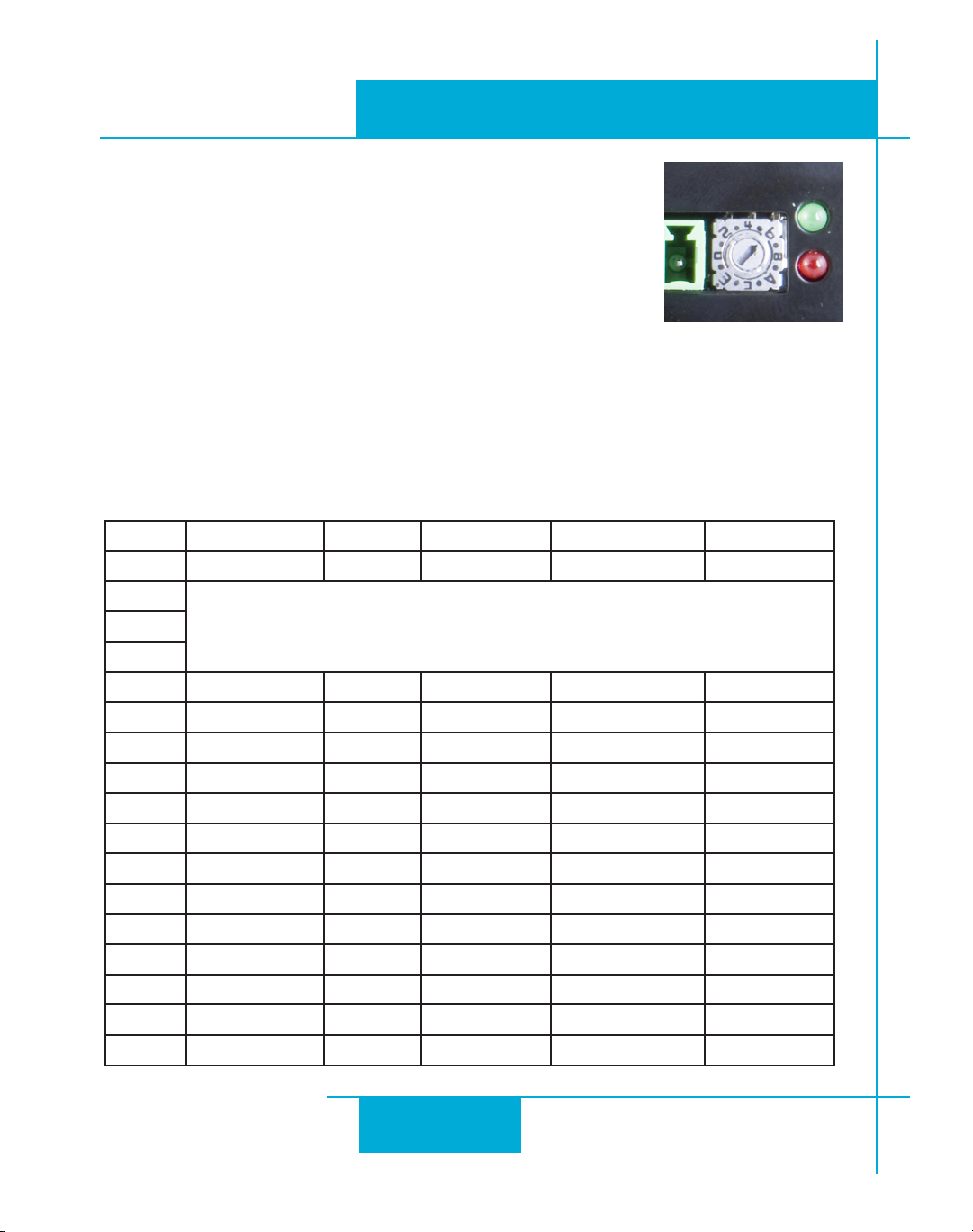
e STR drives are optimized for use with carefully selected motors. To
select a motor, simply move the rotary switch to the leer or number
that corresponds to the motor of your choice. You can do this while
power is on, but it is safer to select the motor before applying power
to the drive so that you do not risk applying too much current to your motor.
If your motor is not on the list, please set the switch to a selection whose rotor inertia, holding
torque and current are within 10% of your motor. Custom congurations can be added for
qualifying applications.
STR4 Motor Table
Current Holding Torque Rotor Inertia
Switch Motor Wiring A oz-in g-cm
0
reserved for custom congurations1
2
3 HT17-068/268 parallel 1.6 31.4 35
4 HT17-071/271 parallel 2 51 54
5 HT17-075/275 parallel 2 62.8 68
6 HT23-394/594 parallel 3.4 76.6 120
7 HT23-398/598 parallel 4.5 159.3 300
8 HT23-401/601 parallel 4.5 237.6 480
9 HT24-100 4 leads 3.36 123 280
A HT24-105 4 leads 4.5 166 450
B HT24-108 4 leads 4.5 332 900
C HT34-485 series 4.5 585 1400
D HT34-486 series 4.5 1113 2680
E HT34-504 series 3.816 396 1100
F HT34-505 series 3.816 849 1850
2
16
Page 17
STR Hardware Manual
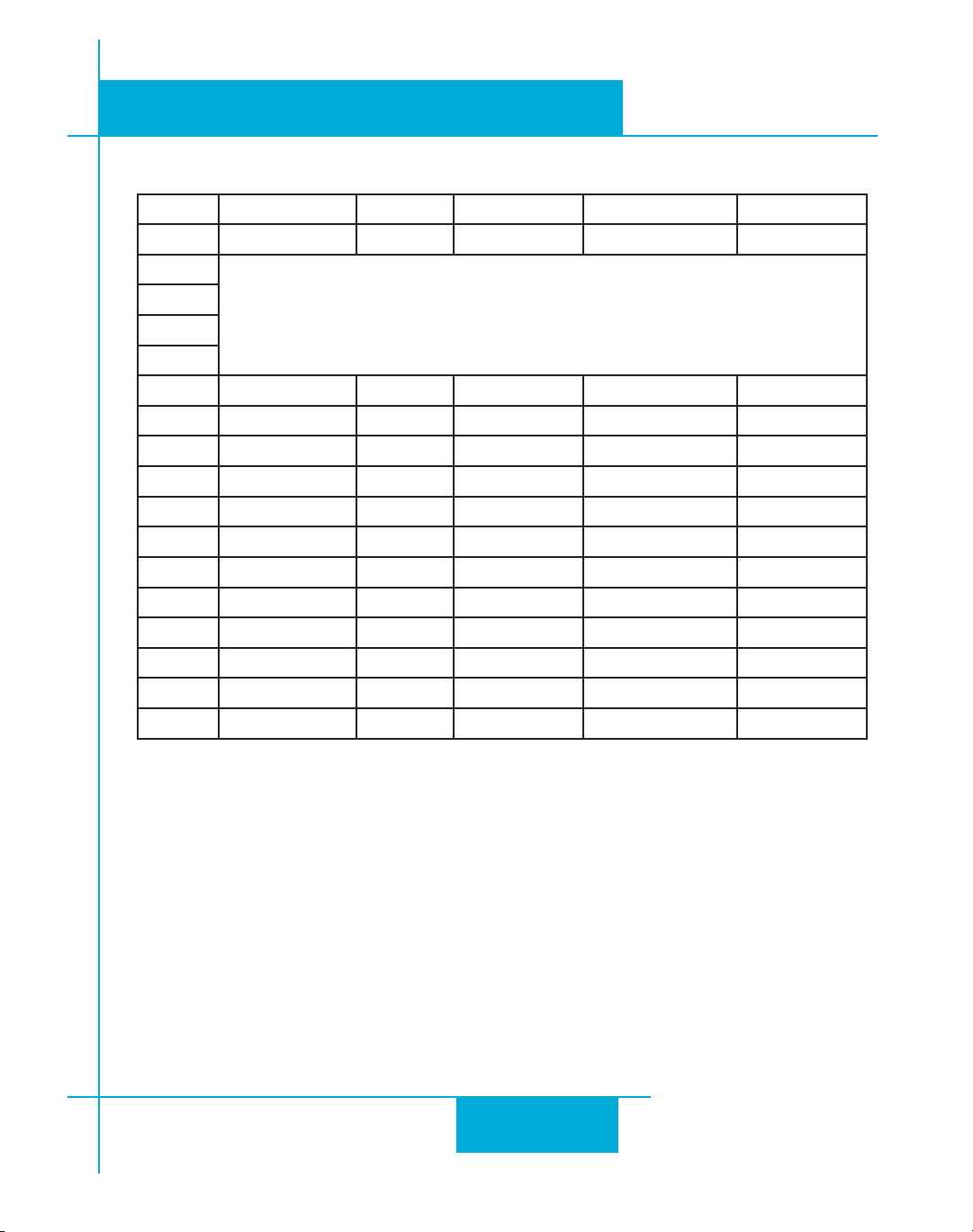
STR8 Motor Table
Max Current Holding Torque Rotor Inertia
Switch Motor Wiring A oz-in g-cm
0
1
reserved for custom congurations
2
3
4 HT23-394/594 parallel 3.4 76.6 120
5 HT23-398/598 parallel 5 177 300
6 HT23-401/601 parallel 5 264 480
7 HT24-100 4 leads 3.36 123 280
8 HT24-105 4 leads 4.8 177 450
9 HT24-108 4 leads 4.8 354 900
A HT34-485 parallel 8 507 1400
B HT34-486 parallel 8 965 2680
C HT34-487 parallel 8 1439 4000
D HT34-504 parallel 7.56 396 1100
E HT34-505 parallel 7.56 849 1850
F HT34-506 parallel 6.72 1260 2750
920-0030E
2/3/2010
2
Step 2: Seing the Current
e maximum current for the motor you have selected is set automatically when you set the
rotary switch. But you may want to reduce the current to save power or lower motor temperature. is is important if the motor is not mounted to a surface that will help it dissipate heat or
if the ambient temperature is expected to be high.
Step motors produce torque in direct proportion to current, but the amount of heat generated
is roughly proportional to the square of the current. If you operate the motor at 90% of rated
current, you’ll get 90% of the rated torque. But the motor will produce approximately 81% as
much heat. At 70% current, the torque is reduced to 70% and the heating to about 50%.
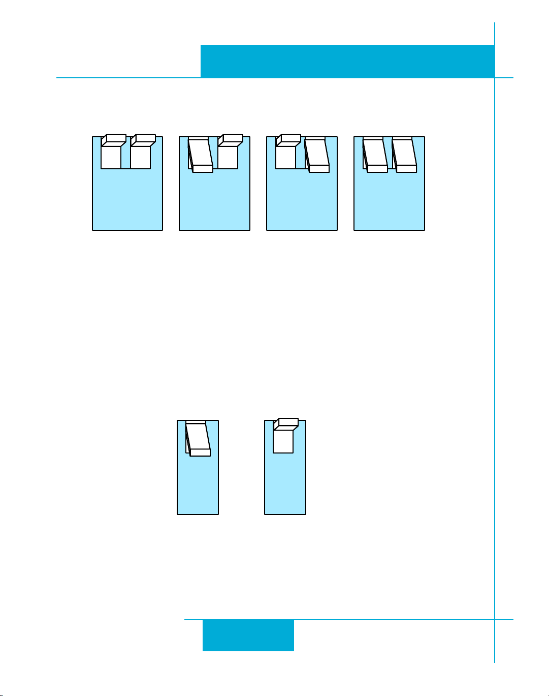
Two of the small switches on the front of the STR drive are used to set the percent of rated
17
Page 18
920-0030E
12
100%
12
90%
12
80%
12
70%
4
50%
4
90%
2/3/2010
current that will be applied to the motor: SW1 and SW2. Please set them according to the
illustration below.
Step 3: Seing Idle Current
Motor heating and power consumption can also be reduced by lowering the motor current
when it is not moving. e STR will automatically lower the motor current when it is idle to
either 50% or 90% of the running current. e 50% idle current seing will lower the holding
torque to 50%, which is enough to prevent the load from moving in most applications. is
reduces motor heating by 75%. In some applications, such as those supporting a vertical load, it
is necessary to provide a high holding torque. In such cases, the idle current can be set to 90%
as shown below.
STR Hardware Manual
18
Page 19
920-0030E
3
5-10X
3
0-4X
STR Hardware Manual
Step 4: Load Inertia
e STR drives include anti-resonance and electronic damping features which greatly improve
motor performance. To perform optimally, the drive must understand the electromechanical
characteristics of the motor and load. Most of this is done automatically when you select the
motor by seing the rotary switch. To further enhance performance, you must set a switch to
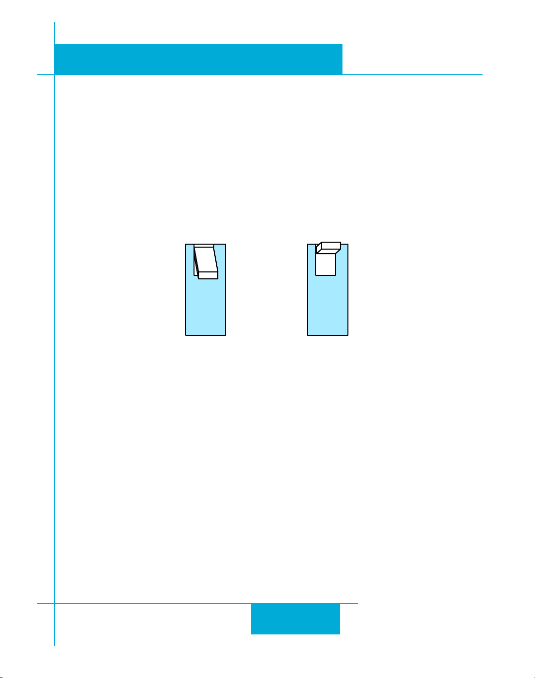
indicate the approximate inertia ratio of the load and motor. e ranges are 0 to 4X and 5 to
10X. e motors table shown in Step 1 of this section include the rotor inertia of each motor.
Please divide the load inertia by the rotor inertia to determine the ratio, then set switch 3 accordingly, as shown. For assistance in calculating the load inertia of your application contact our
Applications department.
2/3/2010
Step 5: Step Size
e STR requires a source of step pulses to command motion. is may be a PLC, an indexer, a
motion controller or another type of device. e only requirement is that the device be able
to produce step pulses whose frequency is in proportion to the desired motor speed, and be
able to smoothly ramp the step speed up and down to produce smooth motor acceleration
and deceleration.
Smaller step sizes result in smoother motion and more precise speed, but also require a higher
step pulse frequency to achieve maximum speed. e smallest step size of the STR drives is
1/20,000th of a motor turn. To command a motor speed of 50 revolutions per second (3000
rpm) the step pulses frequency must be 50 x 20,000 = 1 MHz. Many motion devices, especially
PLCs cannot provide step pulses at such a high speed. If so, the drive must be set for a lower
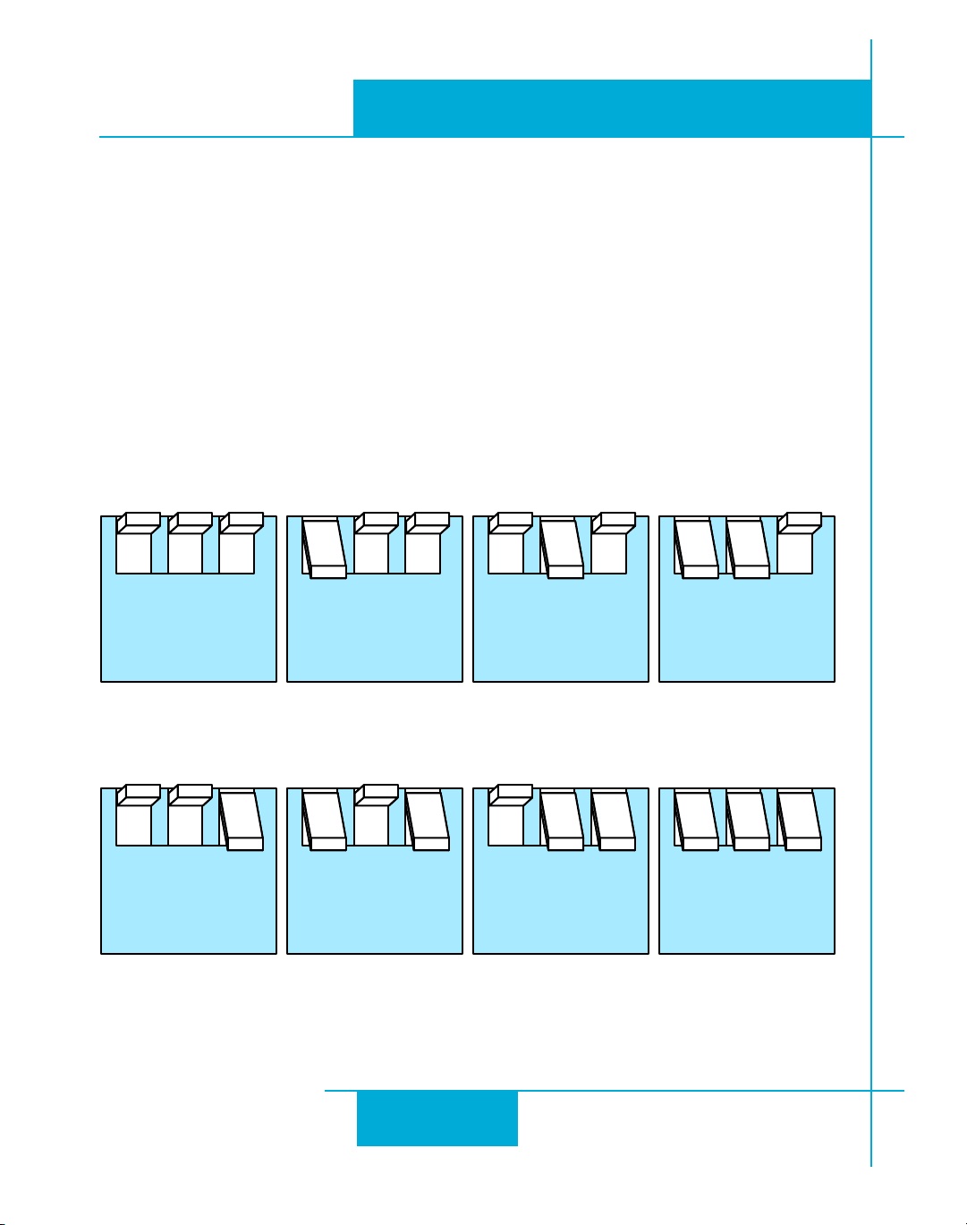
number of steps per revolution. Six dierent seings are provided in the STR drive, as shown
in the table on the next page.
19
Page 20
920-0030E
567
20000
567
12800
567
5000
567
2000
567
400
SMOOTH
567
400
567
200
SMOOTH
567
200
2/3/2010
Please choose the one that best matches the capability of your system.
At lower step resolutions such as 200 steps/ rev (full step) and 400 steps/rev (half step), motors
run a lile rough and produce more audible noise than when they are microstepped (2000
steps/rev and beyond). e STR drives include a feature called “microstep emulation”, also
called “step smoothing”, that can provide smooth motion from coarse command signals. If you
select “200 SMOOTH” or “400 SMOOTH”, this feature is automatically employed to provide
the smoothest possible motion from a less than ideal signal source.
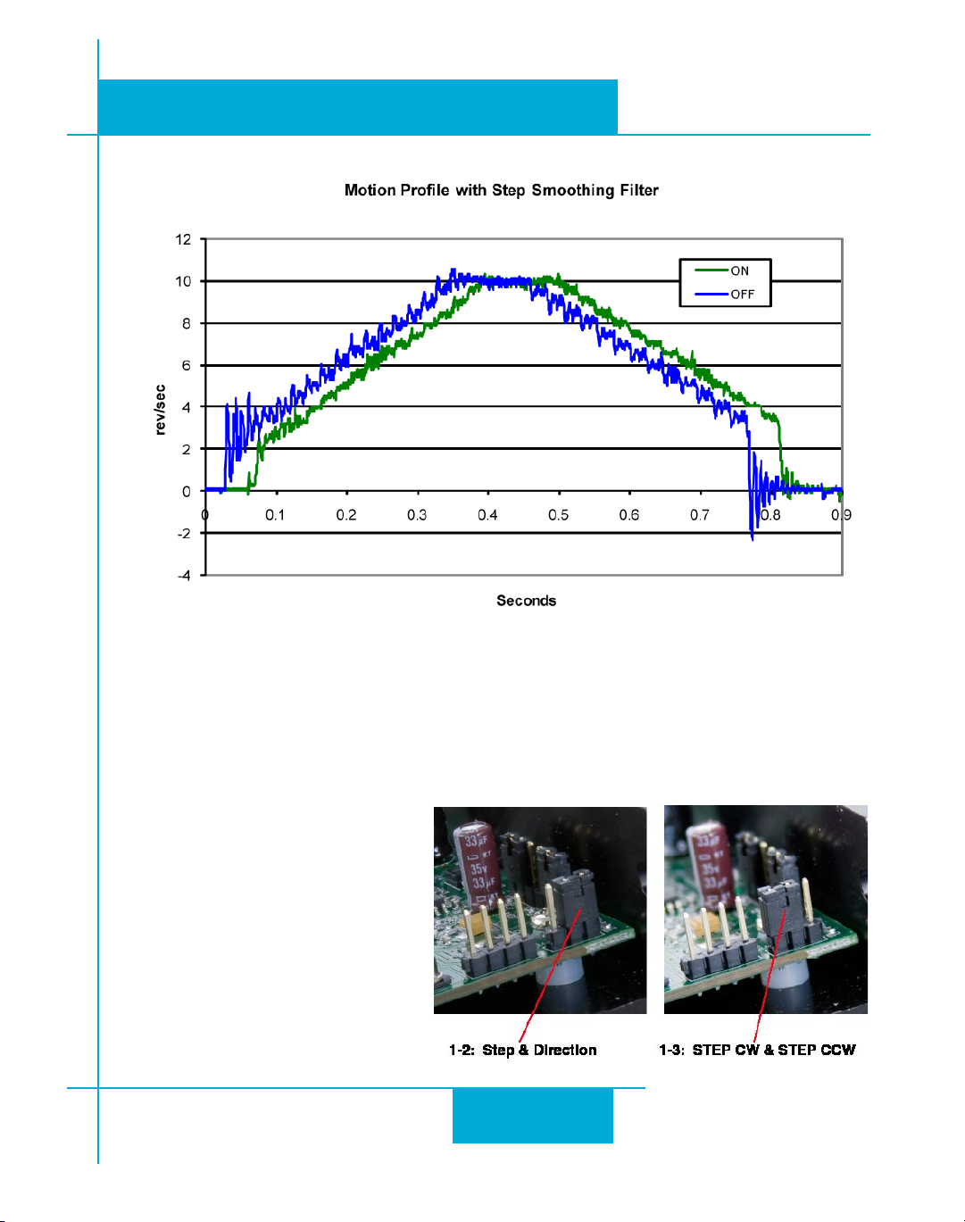
Because a command lter is used as part of the step smoothing process, there will be a slight
delay, or “lag” in the motion. If this delay is objectionable for your application, please choose
the non-ltered seing “200” or “400”. e chart on the next page shows an example of the
STR Hardware Manual
20
Page 21
STR Hardware Manual
920-0030E
2/3/2010
delay that can occur from using the step smoothing lter.
Step 6: Step Pulse Type
Most indexers and motion controllers provide motion commands in the “Step and Direction” format. e Step signal pulses
once for each motor step and the
direction signal commands direction.
However, a few PLCs use a dierent
type of command signal: one signal
pulses once for each desired step in
the clockwise direction (called STEP
CW), while a second signal pulses
for counterclockwise motion (STEP
CCW). e STR drives can accept this
type of signal if you remove the drive
21
Page 22
920-0030E
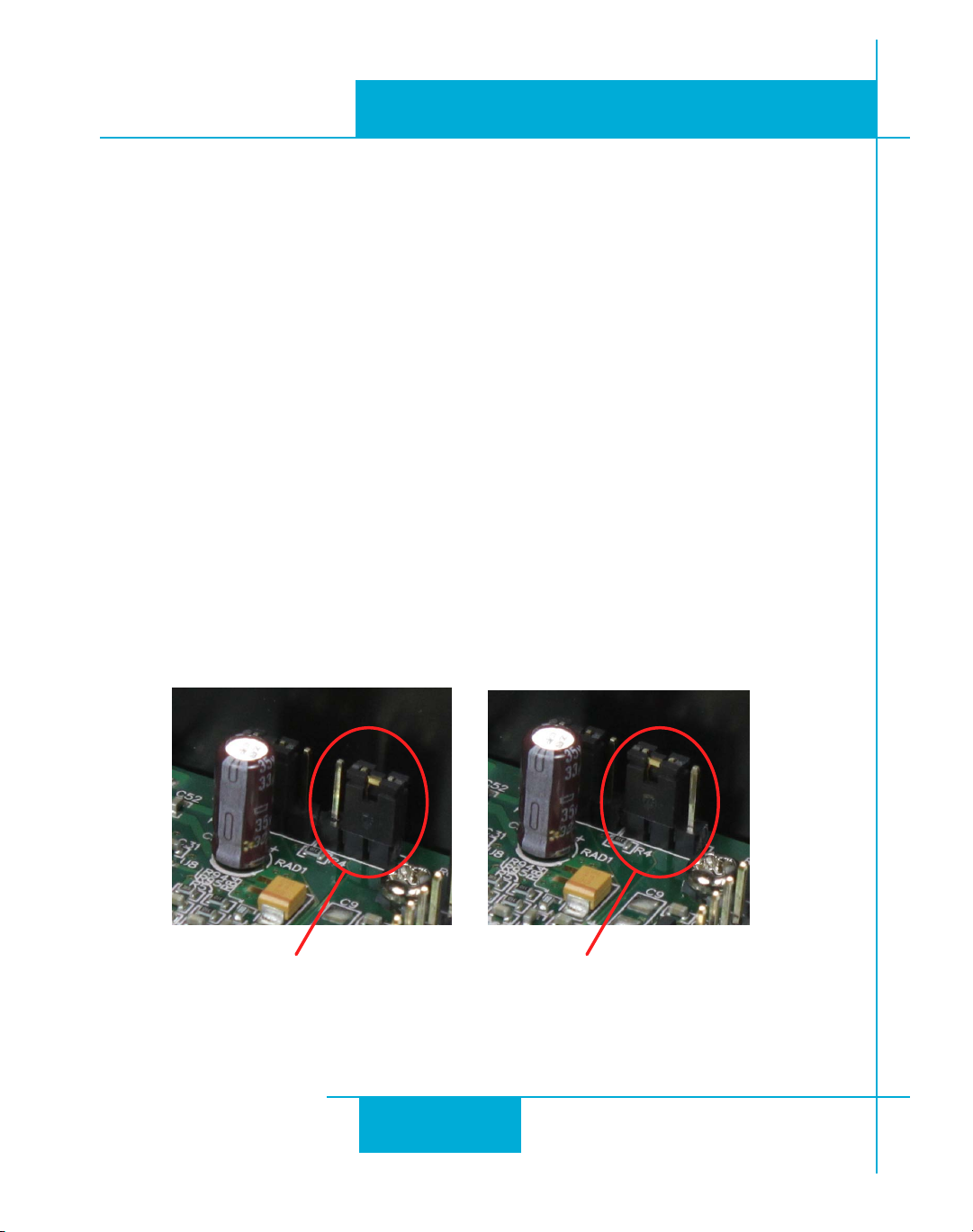
1-2: 2 MHz 1-3: 150 kHz
2/3/2010
cover and move jumper S3 from the “1-2” position to the “1-3” position. In STEP CW/STEP
CCW mode, the CW signal should be connected to the STEP input and the CCW signal to the
DIR input.
Step 7: Step Pulse Noise Filter
Just when you thought there couldn’t be any more to know about step signals, we present one
more seing for your consideration. Electrical noise can aect the STEP signal in a negative way,
causing the drive to think that one step pulse is two or more pulses. is results in extra motion
and inaccurate motor and load positioning. To combat this problem, the STR drives include a
digital noise lter on the STEP and DIR inputs. e default factory seing of this lter is150 kHz,
which works well for most applications.
However, as discussed in Step 5, if you are operating the STR at a high number of steps/rev and
at high motor speeds, you will be commanding the drive at step rates above 150 kHz. In such
cases, you should remove the cover and move jumper S4 from the 150 kHz position (1-3) to
the 2 MHz position (1-2) as shown below.
STR Hardware Manual
Your maximum pulse rate will be the highest motor speed times the steps/rev. For example, 40
revs/second at 20,000 steps/rev is 40 x 20,000 = 800 kHz. Please consider this when deciding if
you must increase the lter frequency.
Self Test
If you are having trouble geing your motor to turn, you may want to try the built-in self test.
22
Page 23
920-0030E
8
ON
8
OFF
SELF TEST
L
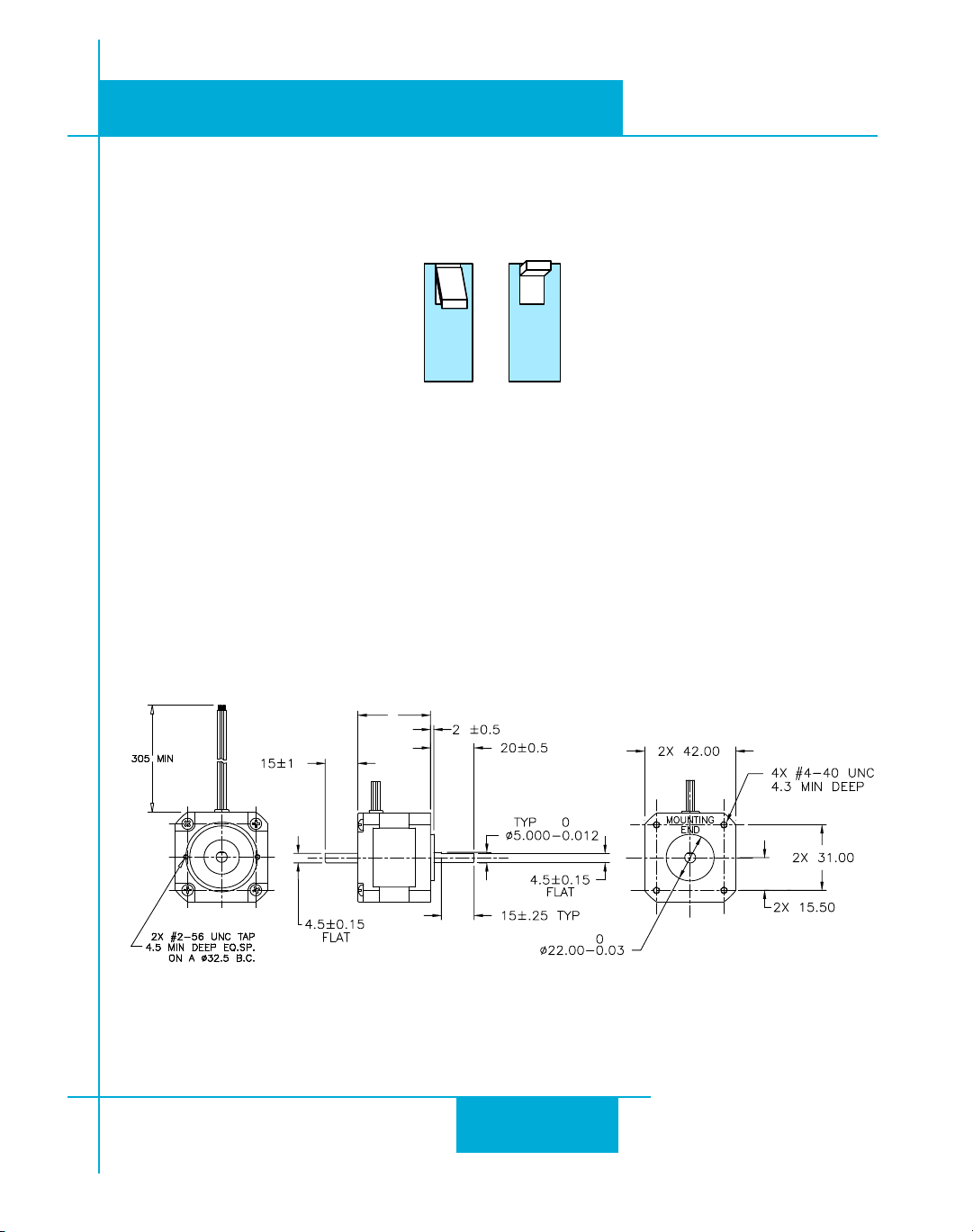
MOTOR LENGTH(L)
HT17-068 33±1 mm
HT17-071 39±1 mm
HT17-075 47±1 mm
HT17-268 33.3 mm MAX
HT17-271 39.8 mm MAX
HT17-275 48.3 mm MAX
ADD ‘D’ TO END OF PART NUMBER TO ADD
REAR SHAFT AND ENCODER HOLES
STR Hardware Manual
2/3/2010
Anytime switch 8 is moved to the ON position, the drive will automatically rotate the motor
back and forth, two turns in each direction. is feature can be used to conrm that the motor
is correctly wired, selected and otherwise operational.
Reference Materials
Motor Outlines
HT17 Outline Drawing
23
Page 24
920-0030E
L
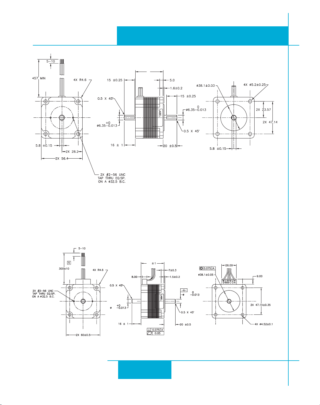
MOTOR LENGTH(L)
HT23-394/594 41 mm MAX
HT23-398/598 54 mm MAX
HT23-401/601 76 mm MAX
ADD ‘D’ TO END OF PART NUMBER TO ADD
REAR SHAFT AND ENCODER HOLES
L
MOTOR LENGTH(L)
HT24-100 44±1 mm
HT24-105 54±1 mm
HT24-108 85±1 mm
8.0
8.0
2/3/2010
STR Hardware Manual
HT23 Outline Drawing
HT24 Outline Drawing
24
Page 25
STR Hardware Manual
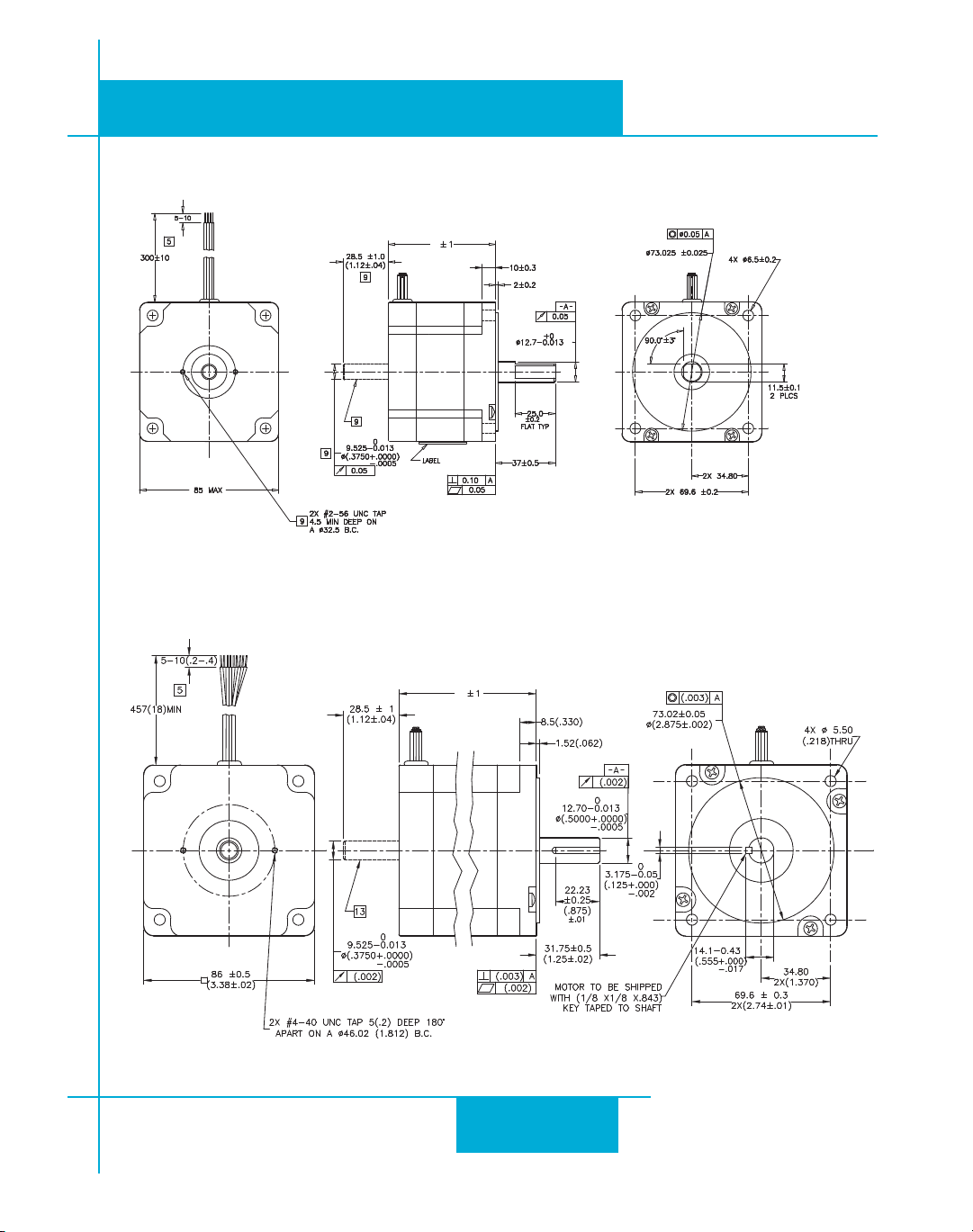
L
MOTOR LENGTH(L)
HT34-485 79 mm
HT34-486 117.5 mm
HT34-487 156 mm
L
MOTOR LENGTH(L)
HT34-504 66.5±1 mm
HT34-505 96±1 mm
HT34-506 125.5±1 mm
HT34-504, 505 & 506 Outline Drawing
920-0030E
2/3/2010
HT34-485, 486, 487 Outline Drawing
25
Page 26
920-0030E
0
10
20
30
40
50
60
0 5 10 15 20 25 30 35 40
oz-in
rps
HT17 with STR4
Connection: Parallel
24v Power Supply , 20,000 steps/rev
HT17-068
HT17-071
HT17-075
0
10
20
30
40
50
60
0 5 10 15 20 25 30 35 40
oz-in
rps
HT17 with STR4
Connection: Parallel
48v Power Supply , 20,000 steps/rev
HT17-068
HT17-071
HT17-075
2/3/2010
Torque-Speed Curves
STR Hardware Manual
26
Page 27
STR Hardware Manual
0
50
100
150
200
250
0 5 10 15 20 25 30 35 40
oz-in
rps
HT23 with STR4
Connection: Parallel
24v Power Supply. 20,000 steps/rev
HT23-394
HT23-398
HT23-401
0
50
100
150
200
250
0 5 10 15 20 25 30 35 40
oz-in
rps
HT23 with STR4
Connection: Parallel
48v Power Supply , 20,000 steps/rev
HT23-394
HT23-398
HT23-401
920-0030E
2/3/2010
27
Page 28
920-0030E
0
50
100
150
200
250
300
350
0 5 10 15 20 25 30 35 40
oz-in
rps
HT24 with STR8
Connection: Parallel
24v Power Supply , 20,000 steps/rev
HT24-100
HT24-105
HT24-108
0
50
100
150
200
250
300
350
0 5 10 15 20 25 30 35 40
oz-in
rps
HT24 with STR8
Connection: Parallel
48v Power Supply , 20,000 steps/rev
HT24-101
HT24-105
HT24-108
2/3/2010
STR Hardware Manual
28
Page 29
STR Hardware Manual
0
100
200
300
400
500
600
700
800
900
0 5 10 15 20 25 30 35 40
oz-in
rps
HT34 with STR4
Connection: Series
Power Supply 48V, 20,000 steps/rev
HT34-504
HT34-505
HT34-485
HT34-486
0
100
200
300
400
500
600
700
800
900
1000
0 5 10 15 20 25 30 35 40
oz-in
rps
HT34 with STR8
Connection: Parallel
Power Supply 24V, 20,000 steps/rev
HT34-504
HT34-505
HT34-506
920-0030E
2/3/2010
29
Page 30
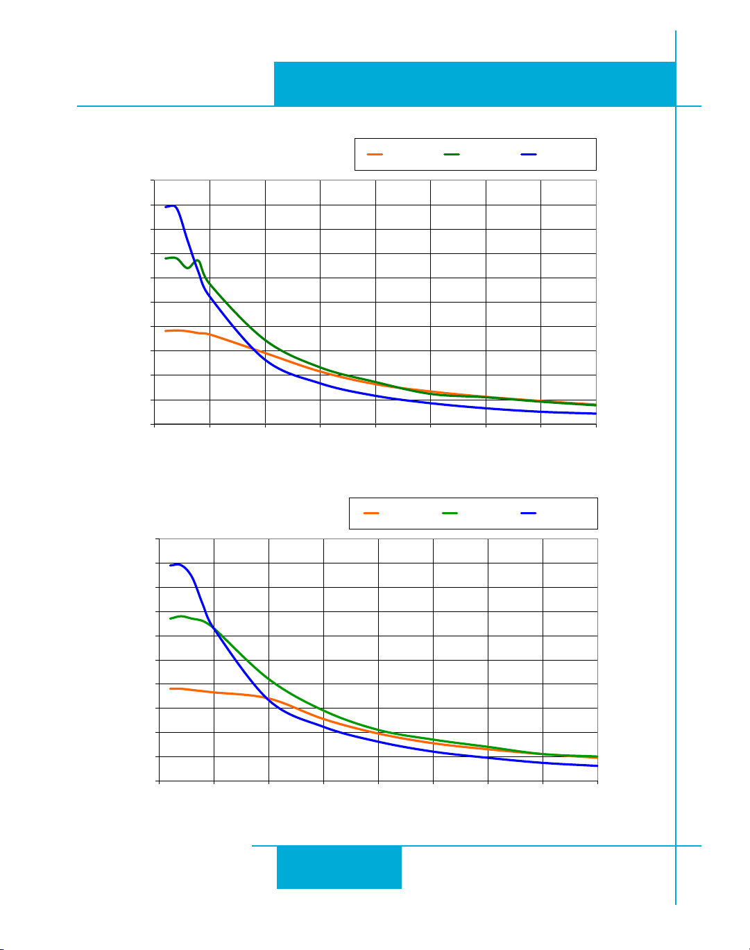
920-0030E
0
100
200
300
400
500
600
700
800
900
1000
0 5 10 15 20 25 30 35 40
oz-in
rps
HT34 with STR8
Connection: Parallel
Power Supply 48V, 20,000 steps/rev
HT34-504
HT34-505
HT34-506
0
100
200
300
400
500
600
700
800
900
1000
0 5 10 15 20 25 30 35 40
oz-in
rps
HT34 with STR8
Connection: Parallel
Power Supply 60V, 20,000 steps/rev
HT34-504
HT34-505
HT34-506
2/3/2010
STR Hardware Manual
30
Page 31
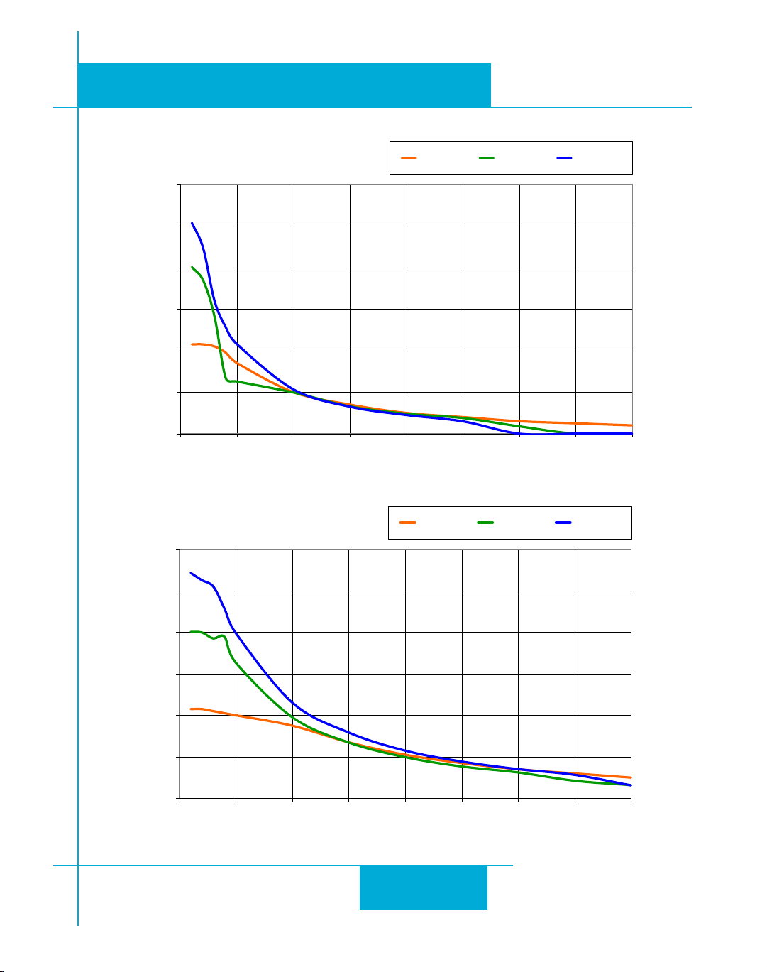
STR Hardware Manual
0
200
400
600
800
1000
1200
0 5 10 15 20 25 30 35 40
oz-in
rps
HT34 with STR8
Connection: Parallel
Power Supply 24V, 20,000 steps/rev
HT34-485
HT34-486
HT34-487
0
200
400
600
800
1000
1200
0 5 10 15 20 25 30 35 40
oz-in
rps
HT34 with STR8
Connection: Parallel
Power Supply 48V, 20,000 steps/rev
HT34-485
HT34-486
HT34-487
920-0030E
2/3/2010
31
Page 32
920-0030E
0
200
400
600
800
1000
1200
0 5 10 15 20 25 30 35 40
oz-in
rps
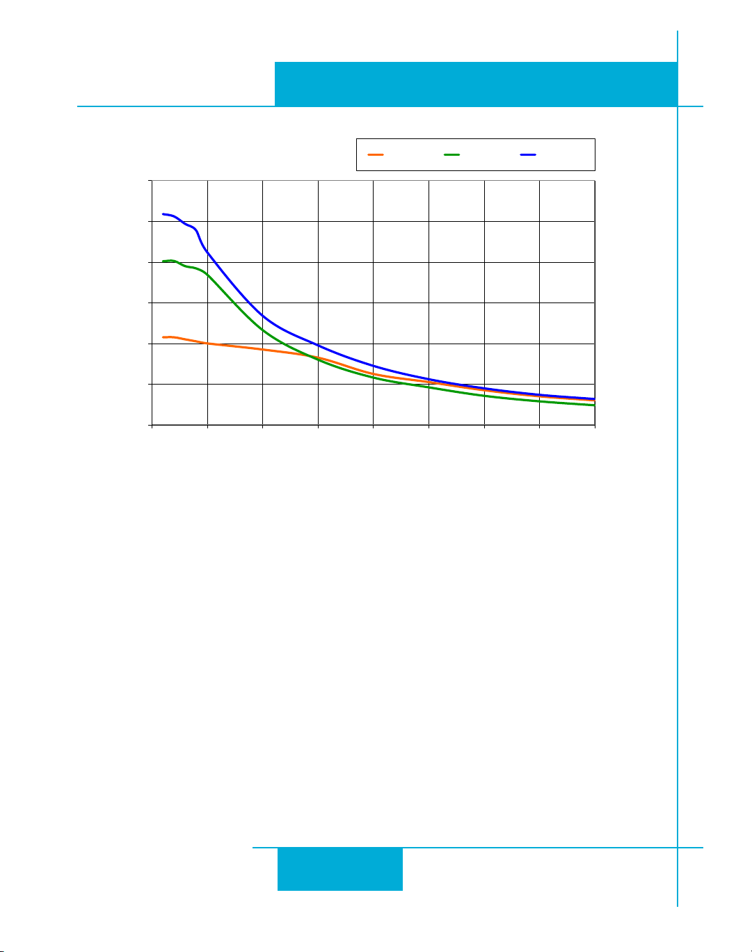
HT34 with STR8
Connection: Parallel
Power Supply 60V, 20,000 steps/rev
HT34-485
HT34-486
HT34-487
2/3/2010
STR Hardware Manual
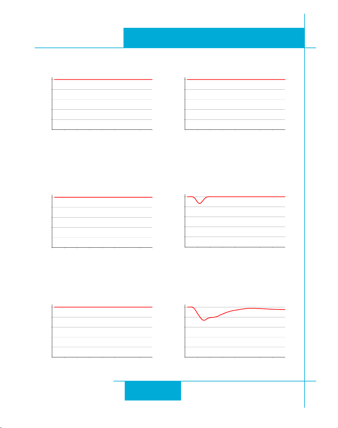
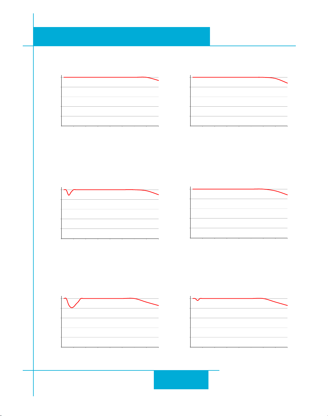
Motor Heating
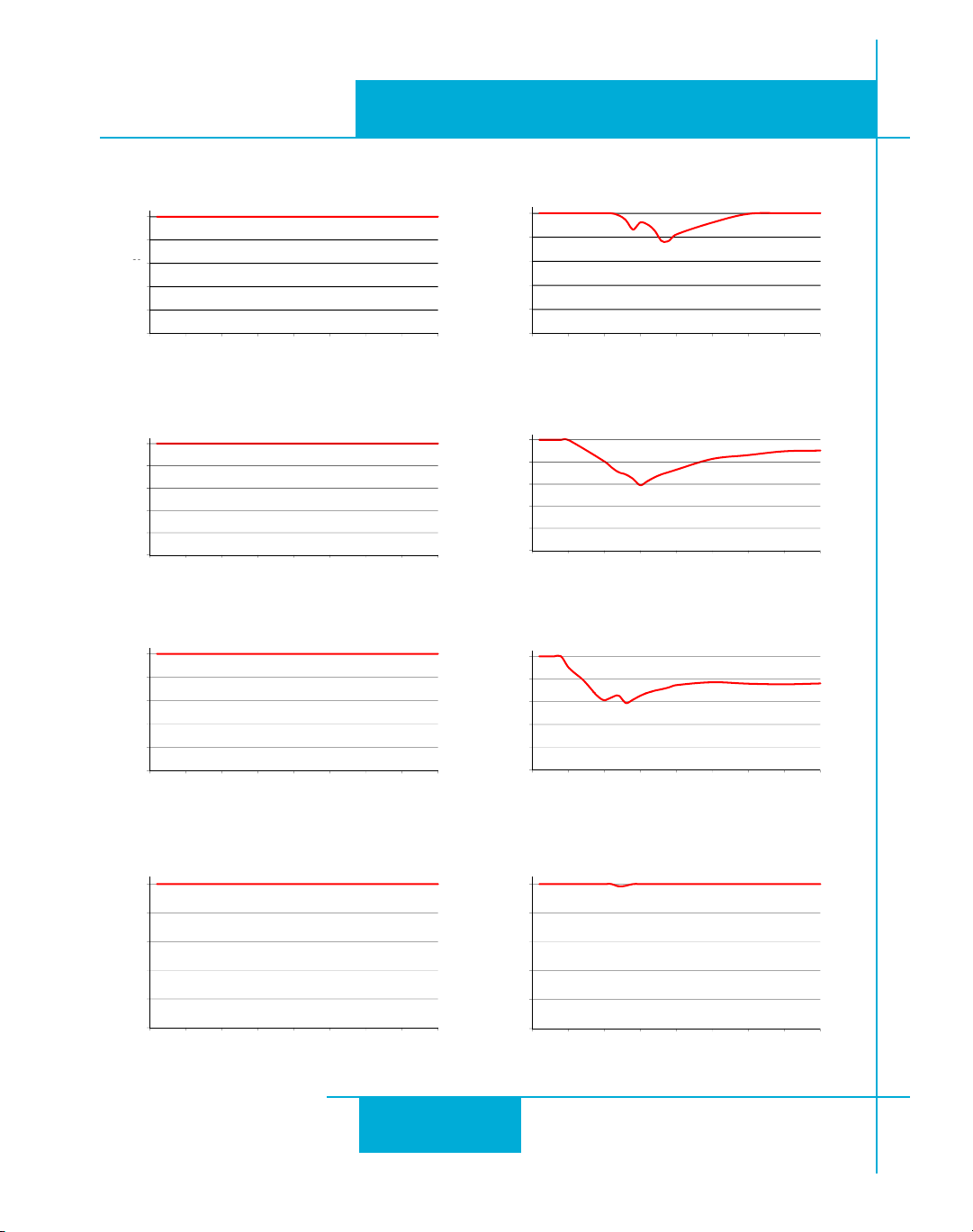
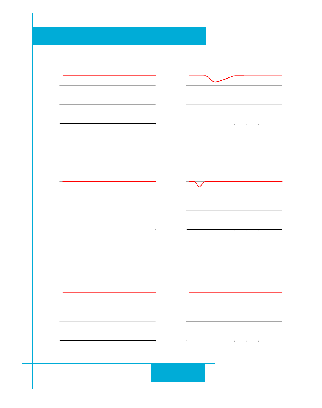
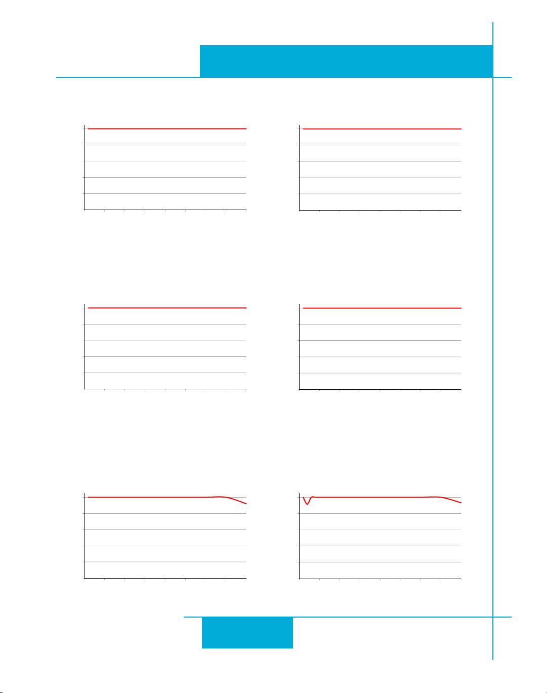
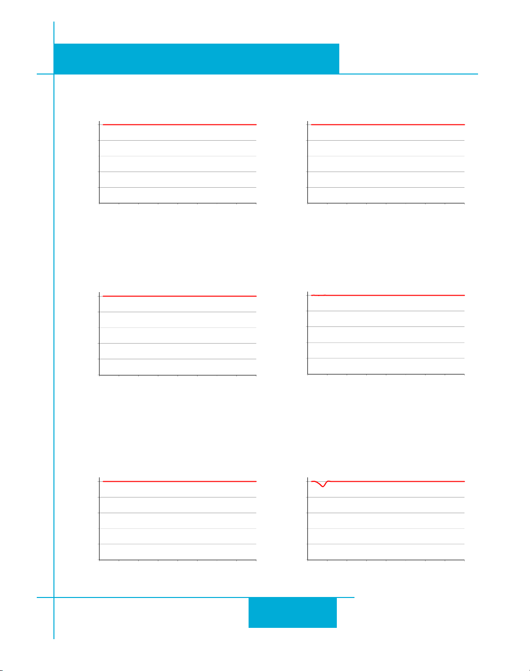
Step motors convert electrical power from the driver into mechanical power to move a load.
Because step motors are not perfectly ecient, some of the electrical power turns into heat on
its way through the motor. is heating is not so much dependent on the load being driven but
rather the motor speed and power supply voltage. ere are certain combinations of speed
and voltage at which a motor cannot be continuously operated without damage.
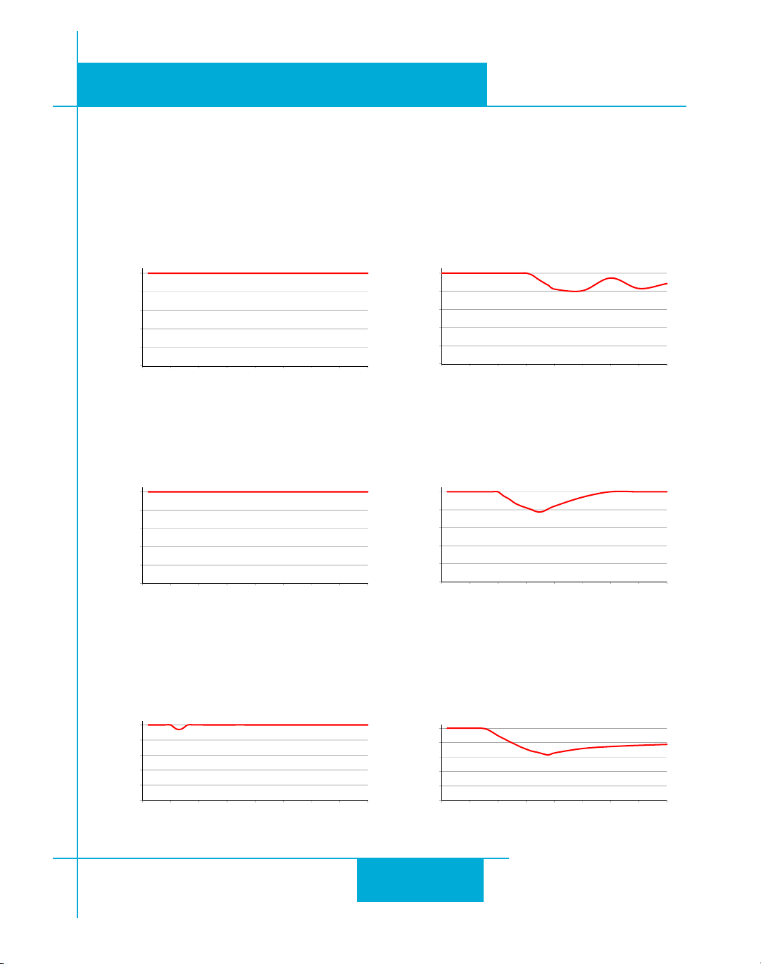
We have characterized the recommended motors in our lab and provided curves showing the
maximum duty cycle versus speed for each motor at commonly used power supply voltages.
Please refer to these curves when planning your application.
Please also keep in mind that a step motor typically reaches maximum temperature aer 30 to
45 minutes of operation. If you run the motor for one minute then let it sit idle for one minute,
that is a 50% duty cycle. Five minutes on and ve minutes o is also 50% duty. However, one
hour on and one hour o has the eect of 100% duty because during the rst hour the motor
will reach full (and possibly excessive) temperature.
32
Page 33
920-0030E
80
100
HT17-068 Max Duty cycle vs Speed
24 VDC, 1.60 Amps @40°C Ambient
on 4.75 x 4.75 x .25 Aluminum Plate
0
20
40
60
0 5 10 15 20 25 30 35 40
% Duty Cycl
e
Speed (RPS)
80
100
HT17-068 Max Duty cycle vs Speed
48 VDC, 1.60 Amps @Ambient of 40
on 4.75 x 4.75 x .25 Aluminum Plate
0
20
40
60
0 5 10 15 20 25 30 35 40
% Duty Cycl
e
Speed (RPS)
80
100
HT17-071 Max Duty Cycle vs Speed
24 VDC, 2.0 Amps 40°C Ambient
on 4.75 x 4.75 x .25 Aluminum Plate
0
20
40
60
0 5 10 15 20 25 30 35 40
% Duty Cycl
e
Speed (RPS)
80
100
HT17-071 Max Duty Cycle vs Speed
48 VDC, 2.0 Amps 40°C Ambient
on 4.75 x 4.75 x .25 Aluminum Plate
0
20
40
60
0 5 10 15 20 25 30 35 40
% Duty Cycl
e
Speed (RPS)
80
100
HT17-075 Max Duty Cycle vs Speed
24 VDC, 2.0 Amps 40°C Ambient
on 4.75 x 4.75 x .25 Aluminum Plate
0
20
40
60
0 5 10 15 20 25 30 35 40
% Duty Cycl
e
Speed (RPS)
80
100
HT17-075 Max Duty cycle vs Speed
48 VDC, 2.0 Amps @Ambient of 40
on 4.75 x 4.75 x .25 Aluminum Plate
0
20
40
60
0 5 10 15 20 25 30 35 40
% Duty Cycl
e
Speed (RPS)
STR Hardware Manual
2/3/2010
e actual temperature of the motor depends on how much heat is conducted, convected or
radiated out of it. Our measurements were made in a 40°C (104°F) environment with the motor
mounted to an aluminum plate sized to provide a surface area consistent with the motor power
dissipation. Your results may vary.
33
Page 34
920-0030E
80
100
HT23-394 Max Duty Cycle vs Speed
48 VDC, 3.4 Amps, 40°C Ambient
on 6.4 x 6.4 x .25 Aluminum Plate
0
20
40
60
0 5 10 15 20 25 30 35 40
% Duty Cycl
e
Speed (RPS)
80
100
HT23-394 Max Duty Cycle vs Speed
24 VDC, 3.4 Amps, 40°C Ambient
on 6.4 x 6.4 x .25 Aluminum Plate
0
20
40
60
0 5 10 15 20 25 30 35 40
% Duty Cycl
e
Speed (RPS)
60
80
100
le
HT23-398 Max Duty cycle vs Speed
24VDC, 5.0Amps, 40°C Ambient
on 6.4 x 6.4 x .25 Aluminum Plate
0
20
40
0 5 10 15 20 25 30 35 40
% Duty Cy
c
Speed (RPS)
60
80
100
le
HT23-398 Max Duty cycle vs Speed
48VDC, 5.0 Amps, 40°C Ambient
on 6.4 x 6.4 x .25 Aluminum Plate
0
20
40
0 5 10 15 20 25 30 35 40
% Duty Cy
c
Speed (RPS)
80
100
HT23-401 Max Duty Cycle vs Speed
24 VDC, 5.0 Amps, 40°C Ambient
on 6.4 x 6.4 x .25 Aluminum Plate
0
20
40
60
0 5 10 15 20 25 30 35 40
% Duty Cycl
e
Speed (RPS)
80
100
HT23-401 Max Duty Cycle vs Speed
48 VDC, 5.0 Amps, 40°C Ambient
on 6.4 x 6.4 x .25 Aluminum Plate
0
20
40
60
0 5 10 15 20 25 30 35 40
% Duty Cycl
e
Speed (RPS)
80
100
HT24-100 Max Duty Cycle vs Speed
24VDC, 3.36A 40 °C Ambient
on a 10 x 10 x .5 Aluminum Plate
0
20
40
60
0 5 10 15 20 25 30 35 40
% Duty Cycl
e
Speed (RPS)
80
100
HT24-100 Max Duty Cycle vs Speed
48VDC, 3.36A 40 °C Ambient
on a 10 x 10 x .5 Aluminum Plate
0
20
40
60
0 5 10 15 20 25 30 35 40
% Duty Cycl
e
Speed (RPS)
2/3/2010
STR Hardware Manual
34
Page 35
STR Hardware Manual
80
100
HT24-105 Max Duty Cycle vs Speed
24VDC, 4.8A 40 °C Ambient
on a 10 x 10 x .5 Aluminum Plate
0
20
40
60
0 5 10 15 20 25 30 35 40
% Duty Cycl
e
Speed (RPS)
80
100
HT24-105 Max Duty Cycle vs Speed
48VDC, 4.8A 40 °C Ambient
on a 10 x 10 x .5 Aluminum Plate
0
20
40
60
0 5 10 15 20 25 30 35 40
% Duty Cycl
e
Speed (RPS)
80
100
HT24-108 Max Duty Cycle vs Speed
24VDC, 4.8A 40 °C Ambient
on a 10 x 10 x .5 Aluminum Plate
0
20
40
60
0 5 10 15 20 25 30 35 40
% Duty Cycl
e
Speed (RPS)
80
100
HT24-108 Max Duty Cycle vs Speed
48VDC, 4.8A 40 °C Ambient
on a 10 x 10 x .5 Aluminum Plate
0
20
40
60
0 5 10 15 20 25 30 35 40
% Duty Cycl
e
Speed (RPS)
80
100
HT34-504 Max Duty Cycle vs Speed
24VDC, 4.5A series 40 °C Ambient
on a 10 x 10 x .5 Aluminum Plate
0
20
40
60
0 5 10 15 20 25 30 35 40
% Duty Cycl
e
Speed (RPS)
80
100
HT34-504 Max Duty Cycle vs Speed
48VDC, 4.5A series 40 °C Ambient
on a 10 x 10 x .5 Aluminum Plate
0
20
40
60
0 5 10 15 20 25 30 35 40
% Duty Cycl
e
Speed (RPS)
920-0030E
2/3/2010
35
Page 36
920-0030E
80
100
HT34-505 Max Duty Cycle vs Speed
24VDC, 4.5A series 40 °C Ambient
on a 10 x 10 x .5 Aluminum Plate
0
20
40
60
0 5 10 15 20 25 30 35 40
% Duty Cycl
e
Speed (RPS)
80
100
HT34-505 Max Duty Cycle vs Speed
48VDC, 4.5A series 40 °C Ambient
on a 10 x 10 x .5 Aluminum Plate
0
20
40
60
0 5 10 15 20 25 30 35 40
% Duty Cycl
e
Speed (RPS)
80
100
HT34-485 Max Duty Cycle vs Speed
24VDC, 4.5A series 40 °C Ambient
on a 10 x 10 x .5 Aluminum Plate
0
20
40
60
0 5 10 15 20 25 30 35 40
% Duty Cycl
e
Speed (RPS)
80
100
HT34-485 Max Duty Cycle vs Speed
48VDC, 4.5A series 40 °C Ambient
on a 10 x 10 x .5 Aluminum Plate
0
20
40
60
0 5 10 15 20 25 30 35 40
% Duty Cycl
e
Speed (RPS)
80
100
HT34-486 Max Duty Cycle vs Speed
24VDC, 4.5A series 40 °C Ambient
on a 10 x 10 x .5 Aluminum Plate
0
20
40
60
0 5 10 15 20 25 30 35 40
% Duty Cycl
e
Speed (RPS)
80
100
HT34-486 Max Duty Cycle vs Speed
48VDC, 4.5A series 40 °C Ambient
on a 10 x 10 x .5 Aluminum Plate
0
20
40
60
0 5 10 15 20 25 30 35 40
% Duty Cycl
e
Speed (RPS)
2/3/2010
STR Hardware Manual
36
Page 37
STR Hardware Manual
80
100
HT34-504 Max Duty Cycle vs Speed
24VDC, 7.56A parallel 40 °C Ambient
on a 10 x 10 x .5 Aluminum Plate
0
20
40
60
0 5 10 15 20 25 30 35 40
% Duty Cycl
e
Speed (RPS)
80
100
HT34-504 Max Duty Cycle vs Speed
48VDC, 7.56A parallel 40 °C Ambient
on a 10 x 10 x .5 Aluminum Plate
0
20
40
60
0 5 10 15 20 25 30 35 40
% Duty Cycl
e
Speed (RPS)
80
100
HT34-504 Max Duty Cycle vs Speed
60VDC, 7.56A parallel 40 °C Ambient
on a 10 x 10 x .5 Aluminum Plate
0
20
40
60
0 5 10 15 20 25 30 35 40
% Duty Cycl
e
Speed (RPS)
80
100
HT34-505 Max Duty Cycle vs Speed
24VDC, 7.56A parallel 40 °C Ambient
on a 10 x 10 x .5 Aluminum Plate
0
20
40
60
0 5 10 15 20 25 30 35 40
% Duty Cycl
e
Speed (RPS)
80
100
HT34-505 Max Duty Cycle vs Speed
48VDC, 7.56A parallel 40 °C Ambient
on a 10 x 10 x .5 Aluminum Plate
0
20
40
60
0 5 10 15 20 25 30 35 40
% Duty Cycl
e
Speed (RPS)
80
100
HT34-505 Max Duty Cycle vs Speed
60VDC, 7.56A parallel 40 °C Ambient
on a 10 x 10 x .5 Aluminum Plate
0
20
40
60
0 5 10 15 20 25 30 35 40
% Duty Cycl
e
Speed (RPS)
920-0030E
2/3/2010
37
Page 38
920-0030E
80
100
HT34-506 Max Duty Cycle vs Speed
24VDC, 6.72A parallel 40 °C Ambient
on a 10 x 10 x .5 Aluminum Plate
0
20
40
60
0 5 10 15 20 25 30 35 40
% Duty Cycl
e
Speed (RPS)
80
100
HT34-506 Max Duty Cycle vs Speed
48VDC, 6.72A parallel 40 °C Ambient
on a 10 x 10 x .5 Aluminum Plate
0
20
40
60
0 5 10 15 20 25 30 35 40
% Duty Cycl
e
Speed (RPS)
80
100
HT34-506 Max Duty Cycle vs Speed
60VDC, 6.72A parallel 40 °C Ambient
on a 10 x 10 x .5 Aluminum Plate
0
20
40
60
0 5 10 15 20 25 30 35 40
% Duty Cycl
e
Speed (RPS)
80
100
HT34-485 Max Duty Cycle vs Speed
24VDC, 8A parallel 40 °C Ambient
on a 10 x 10 x .5 Aluminum Plate
0
20
40
60
0 5 10 15 20 25 30 35 40
% Duty Cycl
e
Speed (RPS)
80
100
HT34-485 Max Duty Cycle vs Speed
48VDC, 8A parallel 40 °C Ambient
on a 10 x 10 x .5 Aluminum Plate
0
20
40
60
0 5 10 15 20 25 30 35 40
% Duty Cycl
e
Speed (RPS)
80
100
HT34-485 Max Duty Cycle vs Speed
60VDC, 8A parallel 40 °C Ambient
on a 10 x 10 x .5 Aluminum Plate
0
20
40
60
0 5 10 15 20 25 30 35 40
% Duty Cycl
e
Speed (RPS)
2/3/2010
STR Hardware Manual
38
Page 39
STR Hardware Manual
80
100
HT34-486 Max Duty Cycle vs Speed
24VDC, 8A parallel 40 °C Ambient
on a 10 x 10 x .5 Aluminum Plate
0
20
40
60
0 5 10 15 20 25 30 35 40
% Duty Cycl
e
Speed (RPS)
80
100
HT34-486 Max Duty Cycle vs Speed
48VDC, 8A parallel 40 °C Ambient
on a 10 x 10 x .5 Aluminum Plate
0
20
40
60
0 5 10 15 20 25 30 35 40
% Duty Cycl
e
Speed (RPS)
80
100
HT34-486 Max Duty Cycle vs Speed
60VDC, 8A parallel 40 °C Ambient
on a 10 x 10 x .5 Aluminum Plate
0
20
40
60
0 5 10 15 20 25 30 35 40
% Duty Cycl
e
Speed (RPS)
80
100
HT34-487 Max Duty Cycle vs Speed
24VDC, 8A parallel 40 °C Ambient
on a 10 x 10 x .5 Aluminum Plate
0
20
40
60
0 5 10 15 20 25 30 35 40
% Duty Cycl
e
Speed (RPS)
80
100
HT34-487 Max Duty Cycle vs Speed
48VDC, 8A parallel 40 °C Ambient
on a 10 x 10 x .5 Aluminum Plate
0
20
40
60
0 5 10 15 20 25 30 35 40
% Duty Cycl
e
Speed (RPS)
80
100
HT34-487 Max Duty Cycle vs Speed
60VDC, 8A parallel 40 °C Ambient
on a 10 x 10 x .5 Aluminum Plate
0
20
40
60
0 5 10 15 20 25 30 35 40
% Duty Cycl
e
Speed (RPS)
920-0030E
2/3/2010
39
Page 40
920-0030E
15
20
25
Loss(W)
STRDriveLosses
60V
48V
24V
0
5
10
1 2 3 4 5 6 7 8
Driver
motorcurrent(A)
2/3/2010
STR Hardware Manual
Drive Heating
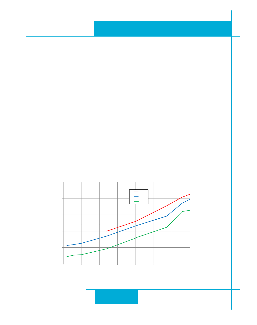
While STR drivers eciently transmit power between the power supply and motor, they do
generate some heat in the process. is will cause the temperature of the drive to rise above
the surrounding air temperature and may also require that the drive be mounted to a heat
conducting metal surface.
For those who wish to calculate the power dissipation and temperature rise, the following information is provided:
drive power dissipation P1.
drive thermal constant R2.
e nal drive case temperature is given by
Tc = Ta + RQ* P
d
where Ta is the ambient temperature of the surrounding air. e case of the drive should not
be allowed to exceed 70°C or the life of the product could be reduced.
Drive thermal constant:
Narrow side of drive mounted on a 13.5” x 13.5” steel plate, .070” thick: RQ =1.0°C/W
Narrow side of drive mounted on a non-heat conducting surface: RQ =2.1°C/W
versus motor current and power supply voltage (see chart)
d
Q
40
Page 41
STR Hardware Manual
12345678
4
3
2
1
0
F
E
D
C
B
A
9
8
7
6
5
2.97” (75.5 mm)
4.65” (118 mm)
.125” (3.2 mm)
1.30”
(33 mm)
2X SLOT 0.17” (4.3 mm)
WIDE, FULL R
0.887” (22.5 mm)
0.996” (25.3 mm)
0.35” (8.9 mm)
0.89” (22.5 mm)
4X DIA .137” (3.5 mm)
4.42 (112 mm)
Mechanical Outline
920-0030E
2/3/2010
41
Page 42
920-0030E
2/3/2010
Technical Specications
STR Hardware Manual
Amplier
Digital Inputs
Digital MOSFET. 20 kHz PWM. Suitable for driving two phase and four
phase step motors with four, six or eight leads.
Supply voltage:
STR4
24-48 VDC (STR4)
Under voltage alarm: 20 VDC
Over voltage shutdown: 60 VDC
STR8
24-75 VDC (STR8)
Under voltage alarm: 20 VDC
Over voltage shutdown: 85 VDC
Motor current:
0.25 to 4.5 amps/phase peak of sine (STR4)
0.5 to 8 amps/phase peak of sine (STR8)
Optically isolated, 5 - 24V logic. Sourcing, sinking or dierential signals can
be used. Drive steps on falling edge of STEP+ input.
Minimum “on” voltage: 4 VDC.
Maximum voltage: 30 VDC.
Input current: 5 mA typ at 4V, 15 mA typ at 30V.
Maximum pulse frequency: 150 kHz or 2 MHz (set by internal jumper)
Minimum pulse width:
3 usec (at 150 kHz seing)
0.25 usec (at 2 MHz seing)
Fault Output
Physical
Photodarlington, 80 mA, 30 VDC max. Voltage drop: 1.2V max at 80 mA.
1.3 x 3.0 x 4.65 inches (33 x 75.5 x 118 mm) overall. 10.8 oz (305 g) including mating connectors.
Ambient temperature range: 0°C to 50°C.
42
Page 43
920-0030E
STR Hardware Manual
2/3/2010
Mating Connectors and Accessories
Mating Connectors
Motor/power supply: PCD P/N ELV06100 (Phoenix Contact 1757051), included with drive.
Signals: PCD P/N ELVH08100 (Phoenix Contact 1803633), included with drive.
Accessories
Regeneration Clamp:
Applied Motion Products RC-050.
43
Page 44
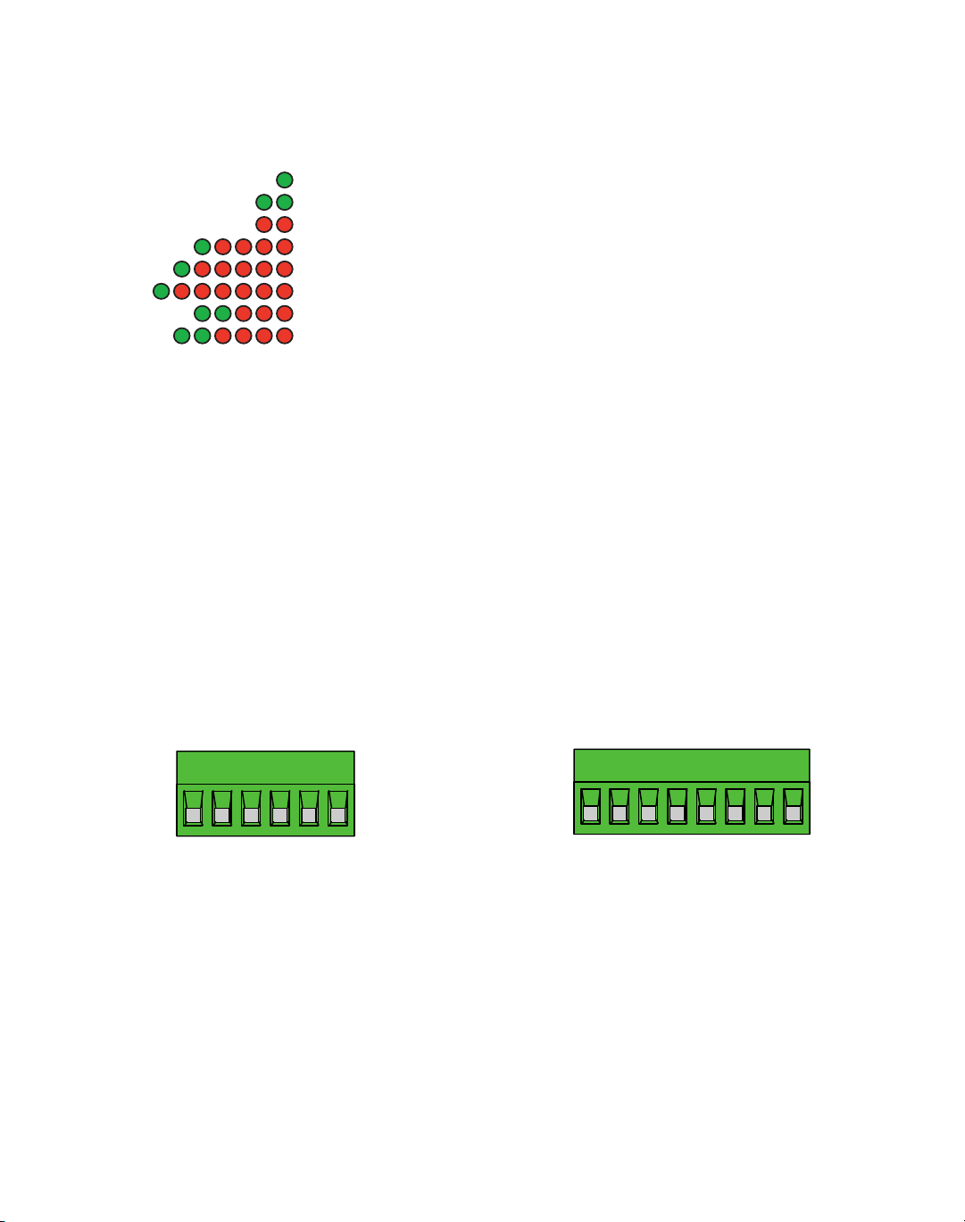
Alarm Codes
Code Error
solid green no alarm, motor disabled
flashing green no alarm, motor enabled
flashing red configuration or memory error
1 green, 4 red power supply voltage too high
1 green, 5 red over current / short circuit
1 green, 6 red open motor winding
2 green, 3 red internal voltage out of range
2 green, 4 red power supply voltage too low
V+
V
–
A–
B+
B
–
A+
STEP+
STEP
–
DIR–
EN+
EN
–
FAULT+
FAULT–
DIR+
Re-Order from
omegamation.com
Omegamation
TM
1-888-55-OMEGA
1-888-55-66342
1-888-55-66342
Intheeventofadrivefaultoralarm,thegreenLEDwillashoneortwotimes,followedbyaseriesofredashes.epattern repeats until the alarm is cleared.
Connector Diagrams
Power and Motor Connector Signal Connector
404 Westridge Drive Watsonville, CA 95076
Tel (831) 761-6555 (800) 525-1609 Fax (831) 761-6544
www.applied-motion.com
 Loading...