

Page 1
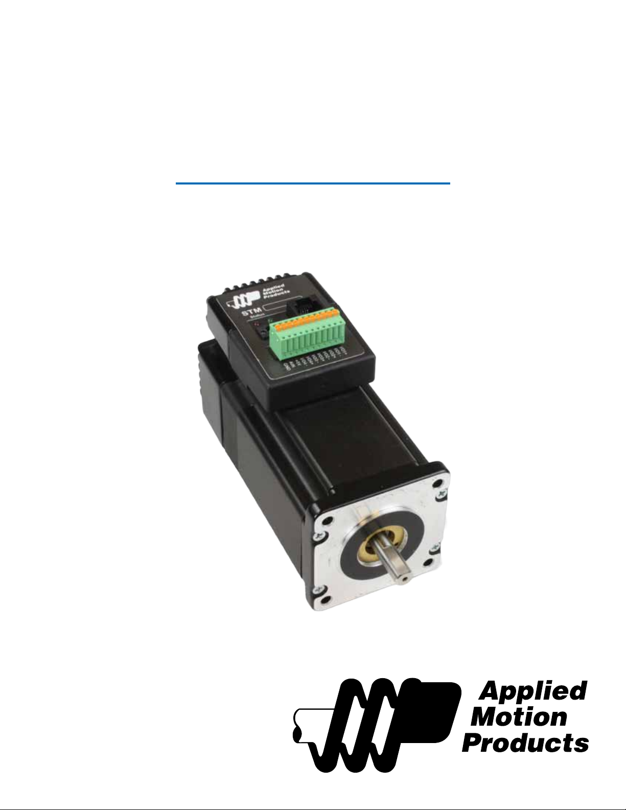
STM24
Re-Order from
omegamation.com
Omegamation
TM
1-888-55-OMEGA
1-888-55-66342
1-888-55-66342
Re-Order from
omegamation.com
Omegamation
TM
1-888-55-OMEGA
1-888-55-66342
1-888-55-66342
Hardware Manual
920-0044D
10/7/2011
Page 2
920-0044D
10/7/2011
STM24 Hardware Manual
Contents
Introduction .............................................................................................................................................................................................................................................3
Features ......................................................................................................................................................................................................................................................3
List of STM24 Model Numbers ....................................................................................................................................................................................................3
Block Diagram (-SF and -QF) ..........................................................................................................................................................................................................4
Block Diagram (-C) ...............................................................................................................................................................................................................................5
Safety Instructions .................................................................................................................................................................................................................................6
Geing Started .......................................................................................................................................................................................................................................7
Mounting the STM24 .........................................................................................................................................................................................................................7
Choosing a Power Supply ...............................................................................................................................................................................................................8
Voltage ...............................................................................................................................................................................................................................................8
Current ...............................................................................................................................................................................................................................................9
Connecting the Power Supply ...................................................................................................................................................................................................11
Installation Requirements for CE Compliance ...........................................................................................................................................................11
+5V Keep-Alive Feature: .......................................................................................................................................................................................................12
Connecting the STM24 Communications ...........................................................................................................................................................................13
Connecting to a PC Using RS-232 ...................................................................................................................................................................................13
Connecting to a Host Using RS-422/485 ....................................................................................................................................................................13
Four-Wire Conguration ...................................................................................................................................................................................................14
Two-Wire Conguration ...................................................................................................................................................................................................15
Assigning RS-485 Addresses ..........................................................................................................................................................................................15
Connecting to an STM24 using USB ..............................................................................................................................................................................16
Inputs and Outputs (-SF and -QF) ...........................................................................................................................................................................................17
Inputs and Outputs (-C) ................................................................................................................................................................................................................18
Connecting Step and Direction Signals ........................................................................................................................................................................19
Connecting Other Signals ....................................................................................................................................................................................................20
Analog Input ................................................................................................................................................................................................................................21
Programmable Output ...........................................................................................................................................................................................................22
Reference Materials ..........................................................................................................................................................................................................................23
Mechanical Outline ..................................................................................................................................................................................................................23
Technical Specications .........................................................................................................................................................................................................25
Torque-Speed Curves ............................................................................................................................................................................................................28
Drive/Motor Heating ...............................................................................................................................................................................................................29
Mating Connectors and Accessories ..............................................................................................................................................................................30
LED Error Codes ........................................................................................................................................................................................................................31
Contacting Applied Motion Products ...........................................................................................................................................................................32
2
Page 3
920-0044D
STM24 Hardware Manual
10/7/2011
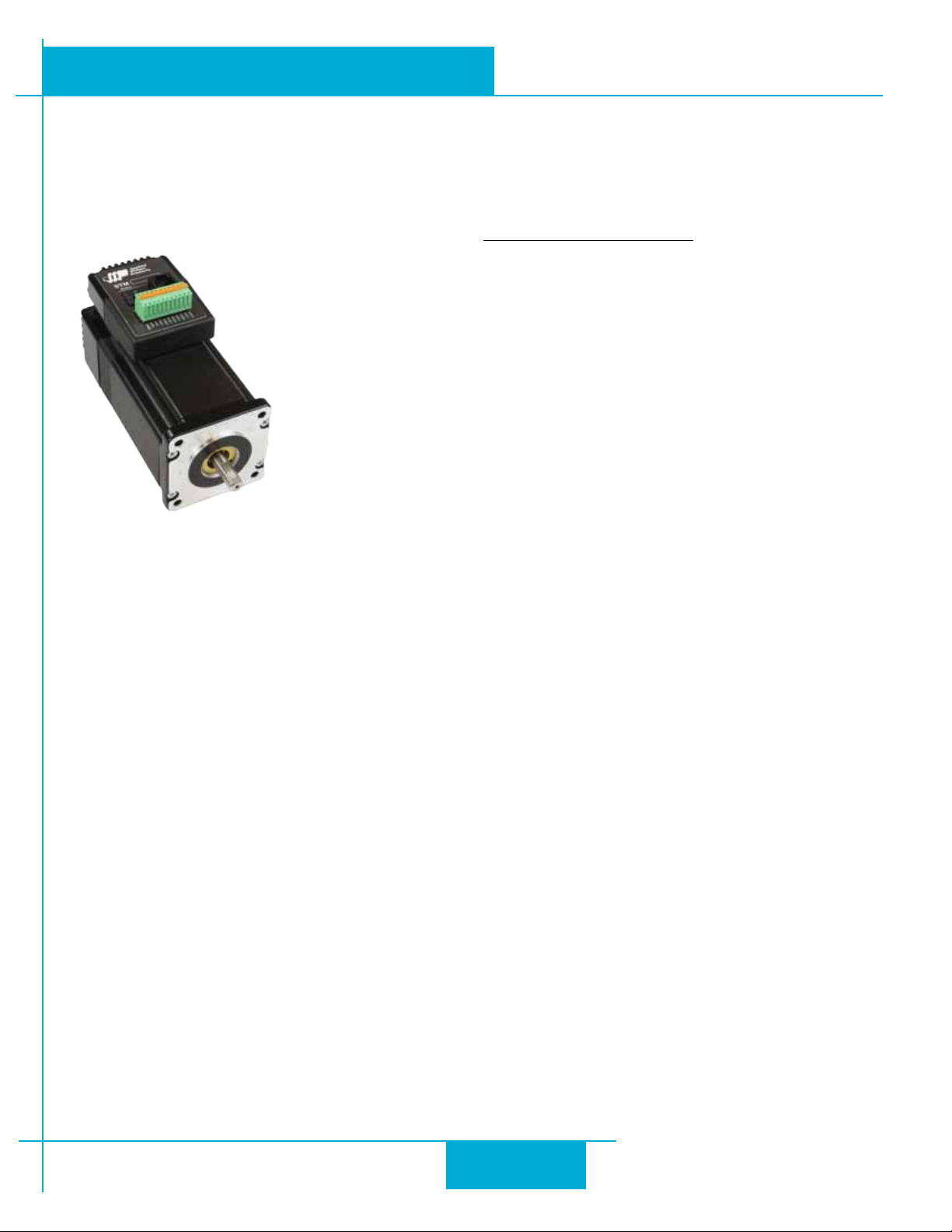
Introduction
ank you for selecting the Applied Motion Products STM24 Drive+Motor. We hope our dedication to performance,
quality and economy will make your motion control project successful. If there’s anything we can do to improve our products or help you use them beer, please call or fax. We’d like to hear from you. Our phone number is (800) 525-1609, or
you can reach us by fax at (831) 761-6544. You can also email [email protected].
Features
• Programmable, micro-stepping digital step Drive+Motor in an integrated package
• Operates from a 12 to 70 volt DC power supply
• Operates in velocity or position mode
• Mid-band anti-resonance
• Accepts analog signals, digital signals and streaming serial commands
• Step input signal smoothing
• Communication options: RS-232, RS-422/485, CANopen
• Optional encoder feedback
• Delivers up to 340 oz-in holding torque
• -SF & -QF: four optically isolated, 5 to 24 volt digital “ex I/O” points (each can be congured as an input or
an output)
• -C: three optically isolated, 5 to 24 volt digital inputs, one optically isolated 30V, 100mA digital output
• Input ltering both hardware and soware
• 0 to 5V analog input for speed and position control (-SF and -QF only)
List of STM24 Model Numbers
STM24SF-3AN STM24SF-3AE
STM24SF-3RN STM24SF-3RE
STM24QF-3AN STM24QF-3AE
STM24QF-3RN STM24QF-3RE
STM24C-3CN STM24C-3CE
Notes:
Last digit indicates 1000 line internal encoder. E: encoder is included, N: no encoder
Next to last digit indicates communication inteface. A = RS-232, R = RS-485, C = CANopen
3
Page 4
12-70 VDC
External
Power Supply
+
I/O 1+
Status
I/O 1-
I/O 2+
I/O 2-
I/O 3+
I/O 3-
I/O 4+
I/O 4-
AIN
GND
GND
+5VDC
+5V
RS-232
TX, RX, GND,+5V
or
RS-485
RX+, RX-, TX+,TX-,GND
-
Digital
Filter
Optical
Isolation
Software
Filter
Digital
Filter
Optical
Isolation
Software
Filter
Digital
Filter
Optical
Isolation
Software
Filter
Optical
Isolation
Software
Filter
I/O Connector
Power
Conn
Comm
Conn
motor
encoder
Optional
MOSFET
PWM
Power
Amplifier
RS-232 or RS-485
5 Volt DC
Power Supply
3.3VDC
Logic
Supply
Voltage &
Temp
Monitor
DSP
Driver
Controller
Over-
Current
Monitor
920-0044D
10/7/2011
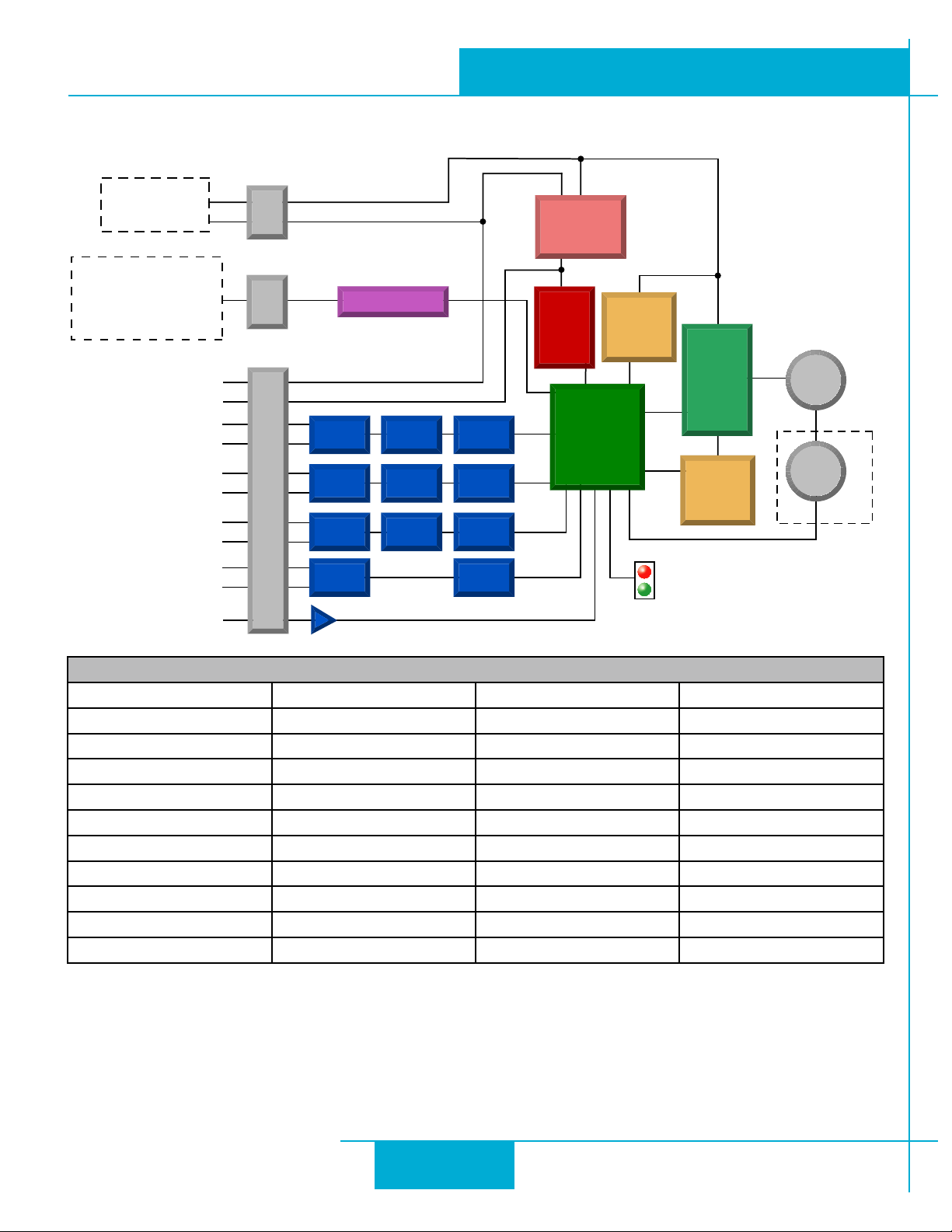
Block Diagram (-SF and -QF)
STM24 Hardware Manual
I/O Functions (congure in software)
I/O 1 I/O 2 I/O 3 I/O 4
Step Input Direction Input
Jog CW Input Jog CCW Input Limit CW Input Limit CCW Input
Enable Input Alarm Reset Input Enable Input Alarm Reset Input
Start/Stop Input Change Speed Input
General Purpose Input General Purpose Input General Purpose Input General Purpose Input
Brake Output Brake Output Brake Output Brake Output
Fault Output Fault Output Fault Output Fault Output
Motion Output Motion Output Motion Output Motion Output
Tach Output Tach Output Tach Output Tach Output
General Purpose Output General Purpose Output General Purpose Output General Purpose Output
4
Page 5
STM24 Hardware Manual
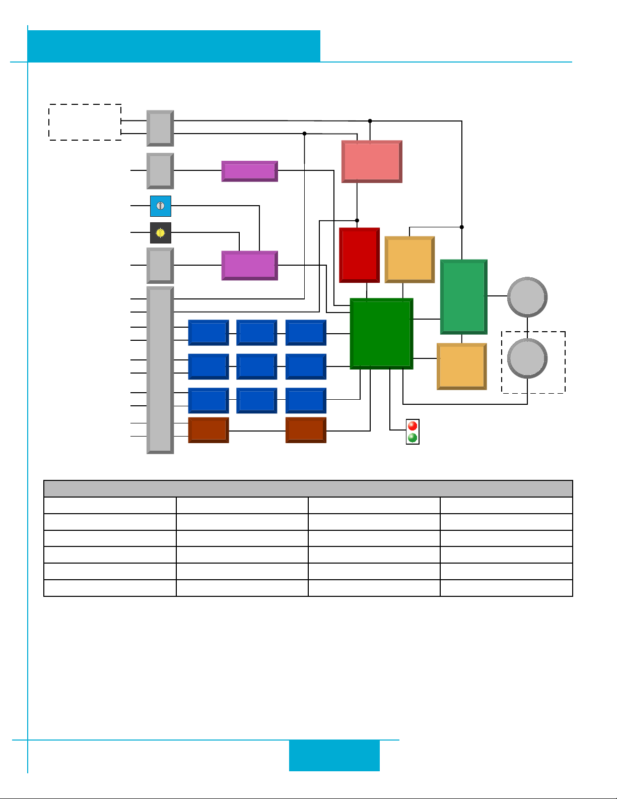
Block Diagram (-C)
920-0044D
10/7/2011
12-70 VDC
External
Power Supply
RS-232
Configuration
Port
Bit Rate
Node ID
CANopen
Network
GND
+5V
IN1+
IN1-
IN2+
IN2
IN3+
IN3
OUT+
OUT
+
-
Conn
Power
5 Volt DC
Power Supply
3.3VDC
Logic
Supply
Voltage &
Temp
Monitor
Comm
5
6
4
3
2
9
1
0
4
5
3
6
2
1
0
F
B
E
C
D
CAN
Conn
7
8
7
8
9
A
Conn
RS-232
CANopen
Controller
MOSFET
GND
+5VDC
encoder
Optical
Isolation
Optical
-
-
-
Isolation
I/O Connector
Optical
Isolation
Optical
Isolation
Digital
Filter
Digital
Filter
Digital
Filter
Software
Filter
Software
Filter
Software
Filter
Software
Filter
DSP
Driver
Controller
Status
PWM
Power
Amplifier
Over-
Current
Monitor
motor
encoder
Optional
I/O Functions (congure in software)
IN1 IN2 IN3 OUT
Clockwise Limit Counterclockwise Limit Home Sensor Fault
General Purpose Input General Purpose Input Enable Input Brake
General Purpose Input Motion
Tach
General Purpose Output
5
Page 6
920-0044D
10/7/2011
STM24 Hardware Manual
Safety Instructions
Only qualied personnel are permied to transport, assemble, commission, and maintain this equipment. Properly qualied personnel are persons who are familiar with the transport, assembly, installation, commissioning and operation of
motors, and who have the appropriate qualications for their jobs. e qualied personnel must know and observe the
following standards and regulations:
IEC 364 resp. CENELEC HD 384 or DIN VDE 0100
IEC report 664 or DIN VDE 0110
National regulations for safety and accident prevention or VBG 4
To minimize the risk of potential safety problems, you should follow all applicable local and national codes that regulate
the installation and operation of your equipment. ese codes vary from area to area and it is your responsibility to determine which codes should be followed, and to verify that the equipment, installation, and operation are in compliance
with the latest revision of these codes.
Equipment damage or serious injury to personnel can result from the failure to follow all applicable codes and standards.
We do not guarantee the products described in this publication are suitable for your particular application, nor do we
assume any responsibility for your product design, installation, or operation.
• Read all available documentation before assembly and commissioning. Incorrect handling of products in this
manual can result in injury and damage to persons and machinery. Strictly adhere to the technical information
on the installation requirements.
• It is vital to ensure that all system components are connected to earth ground. Electrical safety is impossible
without a low-resistance earth connection.
• e STM24 drives contain electrostatically sensitive components that can be damaged by incorrect handling.
Discharge yourself before touching the product. Avoid contact with high insulating materials (articial fabrics,
plastic lm, etc.). Place the product on a conductive surface.
• During operation keep all covers and cabinet doors shut. Otherwise, there are deadly hazards that could
possibility cause severe damage to health or the product.
• In operation, depending on the degree of enclosure protection, the product can have bare components
that are live or have hot surfaces. Control and power cables can carry a high voltage even when the motor is
not rotating.
• Never pull out or plug in the product while the system is live. ere is a danger of electric arcing and danger
to persons and contacts.
• Aer powering down the product, wait until both LEDs are completely dark before touching live sections of
the equipment or undoing connections (e.g., contacts, screwed connections). To be safe, measure the contact
points with a meter before touching.
Be alert to the potential for personal injury. Follow the recommended precautions and safe operating practices included
with the alert symbols. Safety notices in this manual provide important information. Read and be familiar with these
instructions before aempting installation, operation, or maintenance. e purpose of this section is to alert users to
possible safety hazards associated with this equipment and the precautions that need to be taken to reduce the risk of
personal injury and damage to the equipment.
Failure to observe these precautions could result in serious bodily injury, damage to the equipment, or operational difculty.
6
Page 7
920-0044D
STM24 Hardware Manual
10/7/2011
Geing Started
is manual describes the use of four dierent drive models. What you need to know and what you must have depends
on the drive model. For all models, you’ll need the following:
• a 12 - 70 volt DC power supply. Please read the section entitled Choosing a Power Supply for help in choosing the right power supply.
• a small at blade screwdriver for tightening the connectors (included).
• a personal computer running Microso Windows 98, 2000, NT, Me , XP, Vista or 7 (32 or 64 bit).
•
ST Congurator
ucts/soware.
• An Applied Motion programming cable (included with RS-232 models; USB and RS-485 adaptors are avail-
able from Applied Motion, see the Accessories section for part numbers)
If you’ve never used an STM24 drive you’ll need to get familiar with the drive and the set up soware before you try to
deploy the system in your application. We strongly recommend the following:
™ and
Q Programmer
™ soware applications, available at www.applied-motion.com/prod-
1. For -Q drives, download and install the
able at www.applied-motion.com/products/soware. For -S and -C models, install the
2. Launch the soware by clicking Start...Programs...Applied Motion...
3. Connect the drive to your PC using the programming cable. When using RS-485, it must be set up in the
4-Wire conguration (See “Connecting to a host using RS-485” below).
4. Connect the drive to the power supply.
5. Apply power to the drive.
6. e soware will recognize your drive, display the model and rmware version and be ready for action.
ST Congurator
™ and
Q Programmer
™ soware applications, avail-
ST Congurator
™.
Mounting the STM24
As with any stepper motor the STM24 must be mounted so as to provide maximum heat-sinking and air-ow. Keep
space around the Drive+Motor to allow convected air-ow.
• Never use your Drive+Motor in a space where there is no air ow or where other devices cause the sur-
rounding air to be more than 40°C.
• Never put the drive where it can get wet or where metal or other electrically conductive particles can get
on the circuitry.
• Always provide airow around the Drive+Motor .
7
Page 8
920-0044D
10/7/2011
Choosing a Power Supply
When choosing a power supply, there are many things to consider. If you are manufacturing equipment that will be sold
to others, you probably want a supply with all the safety agency approvals. If size and weight are an issue use a switching
supply.
You must also decide what size of power supply (in terms of voltage and current) is needed for your application.
Voltage
e STM24 is designed to give optimum performance between 24 and 70 volts DC. Choosing the voltage depends on
the performance needed and Drive+Motor heating that is acceptable and/or does not cause a drive over-temperature.
Higher voltages will give higher speed performance but will cause the Drive+Motor to operate at higher temperatures.
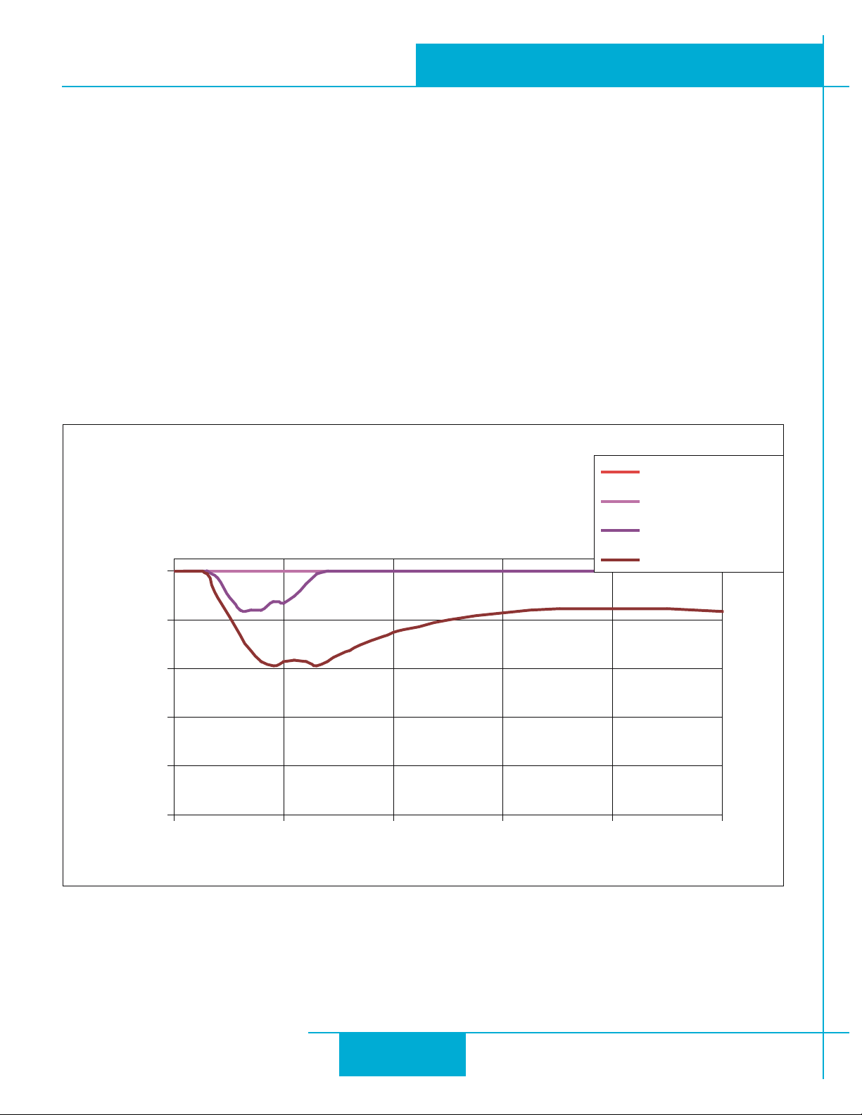
Using power supplies with voltage outputs that are near the drive maximum may reduce the operational duty-cycle signicantly. See the chart below to determine thermal performance at dierent power supply voltages
If you choose an unregulated power supply, make sure the no load voltage of the supply does not exceed the drive’s
maximum input voltage specication.
STM24 Hardware Manual
STM24X-3 Max Duty Cycle vs Speed
6A/phase, 40°C Ambient
Mounted on a 162 x 162 x 6 (mm)
Aluminum Plate
12V Duty Cycle
24V Duty Cycle
48V Duty Cycle
100
e l c y C y t u D %
65V Duty Cycle
80
60
40
20
0
0 10 20 30 40 50
Speed (RPS)
8
Page 9
No Load
No Load
920-0044D
STM24 Hardware Manual
10/7/2011
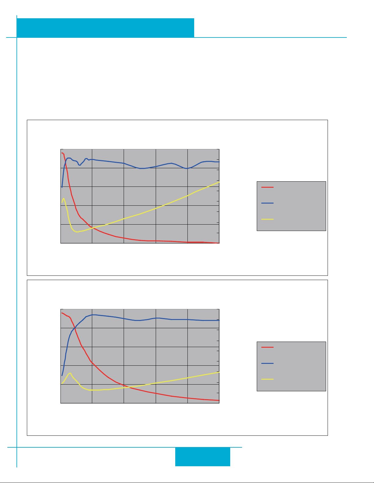
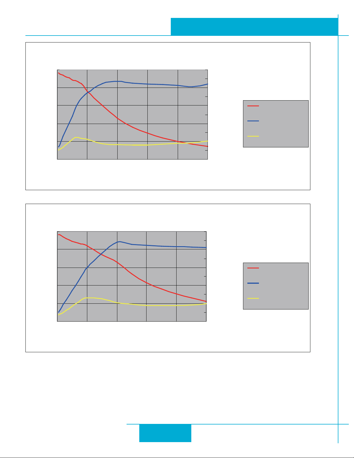
Current
e maximum supply current required by the STM24 is shown in the chart below with dierent power supply voltage
inputs. You will note in the chart that the Drive+Motor does not draw as much current as the motor itself. at’s because
the STM24 uses switching ampliers, converting a high voltage and low current into lower voltage and higher current.
e more the power supply voltage exceeds the motor voltage, the less current you’ll need from the power supply.
Also note that the current draw is signicantly dierent at higher speeds depending on the torque load to the motor.
Estimating your current needs may require a good analysis of the load the motor will encounter.
STM24-3 12V Power Supply Current
Motor Current: 6A/phase
2.5
2
1.5
1
Torque(N.m)
0.5
0
4.50
4.00
3.50
3.00
2.50
2.00
1.50
1.00
0.50
0.00
Torque
Amps
Supply Current
Supply Current
Torque(N.m)
0 10 20 30 40 50
Speed(RPS)
STM24-3 24V Power Supply Current
Motor Current: 6A/phase
2.5
2
1.5
1
0.5
0
0 10 20 30 40 50
Speed(RPS)
4.50
4.00
3.50
3.00
2.50
2.00
1.50
1.00
0.50
0.00
Torque
Amps
Supply Current
Supply Current
9
Page 10
No Load
920-0044D
10/7/2011
2.5
1.5
Torque(N.m)
0.5
STM24-3 48V Power Supply Current
Motor Current: 6A/phase
2
1
0
0 10 20 30 40 50
Speed(RPS)
STM24 Hardware Manual
5.00
4.50
4.00
3.50
3.00
2.50
2.00
1.50
1.00
0.50
0.00
Amps
Torque
Supply Current
Supply Current
Torque(N.m)
STM24-3 70V Power Supply Current
Motor Current: 6A/phase
2.5
2
1.5
1
0.5
0
0 10 20 30 40 50
Speed(RPS)
5.00
4.50
4.00
3.50
3.00
2.50
2.00
1.50
1.00
0.50
0.00
Torque
Amps
Supply Current
Supply Current
10
Page 11
920-0044D
STM24 Hardware Manual
10/7/2011
Connecting the Power Supply
If you need information about choosing a power supply, please read “Choosing a Power Supply” located above in this
manual.
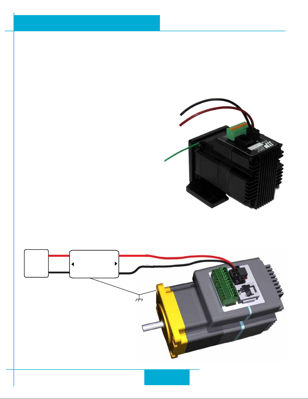
Connect the motor power supply “+” terminal to the driver terminal labeled “+”. Connect power supply “-” to the drive
terminal labeled “-”. Use 16 to 20-gauge wire. e STM24 contains an internal fuse that connects to the power supply +
terminal. is fuse is not user replaceable. If you want to install a user serviceable fuse in your system install a 5 amp fast
acting fuse in line with the + power supply lead.
• Connect the red wire to power supply +
• Connect the black wire to power supply -
• Connect the green wire to earth ground
Be careful not to reverse the wires. Reverse connection
may open the internal fuse on your driver and void your
warranty.
Installation Requirements for CE Compliance
In order to meet the EMC Directive of CE, a line lter must be installed between the DC power supply and the STM24
as shown below.
EMI Filter
P/N:092.00823.00 (LCR)
DC
Power
Input
V+
V-
L
LINE
N
L
LOAD
N
V+
V-
GND
11
Page 12
920-0044D
10/7/2011
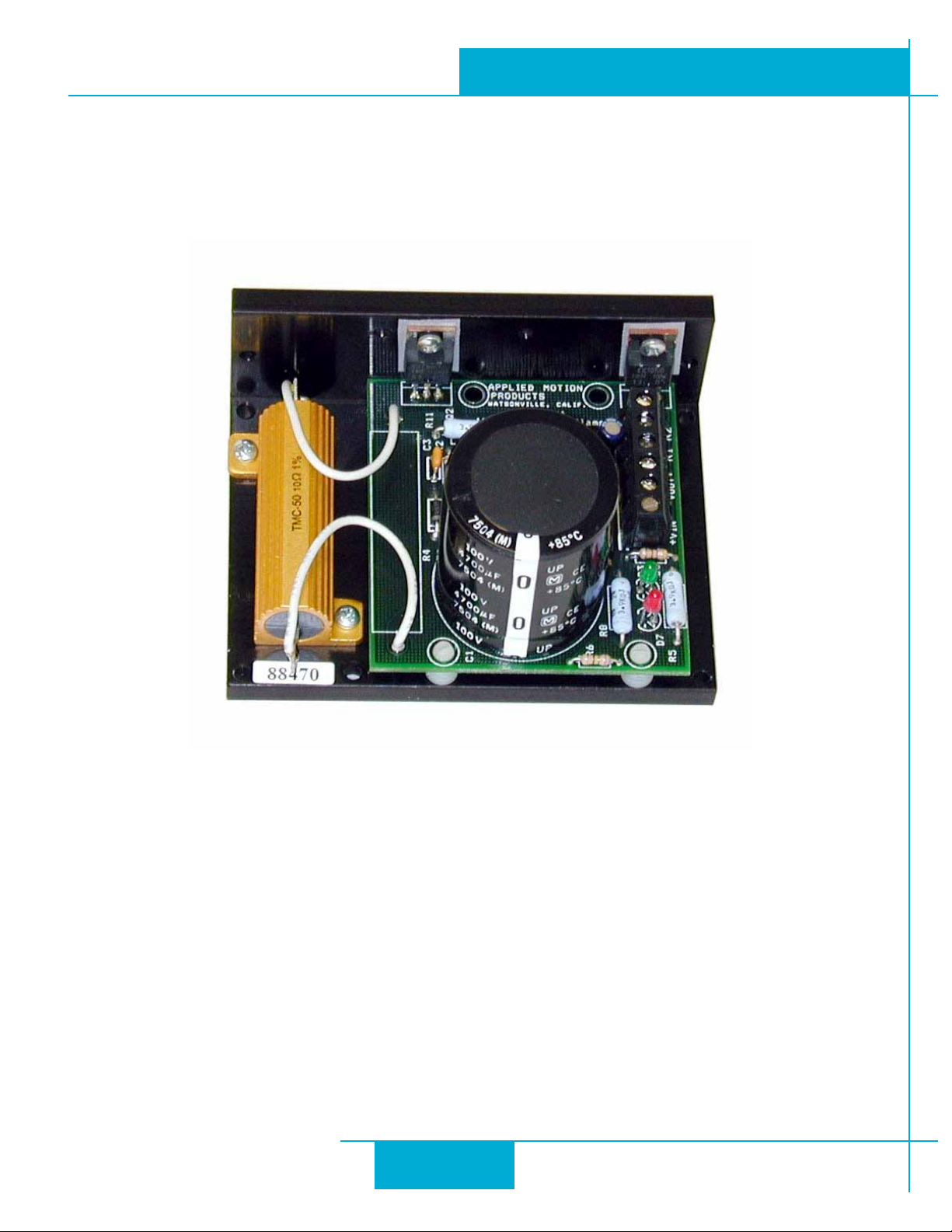
If you plan to use a regulated power supply you may encounter a problem with regeneration. If you rapidly decelerate a
load from a high speed, much of the kinetic energy of that load is transferred back to the power supply. is can trip the
over-voltage protection of a switching power supply, causing it to shut down. We oer the RC-050 “regeneration clamp”
to solve this problem. If in doubt, buy an RC-050 for your rst installation. If the “regen” LED on the RC-050 never ashes,
you don’t need the clamp.
STM24 Hardware Manual
RC-050 Regen Clamp
+5V Keep-Alive Feature:
+5Volts can be fed to the +5V terminal to keep the logic alive when the DC bus voltage is removed. is is very useful
when an encoder is present, as the position of the system is then known when the DC bus is re-applied. An internal voltage fault will have to be cleared and the motor re-enabled when the DC bus is re-applied. A .4 Amp or larger supply is
required for the keep-alive supply.
12
Page 13
920-0044D
STM24 Hardware Manual
10/7/2011
Connecting the STM24 Communications
e STM24 is available with two types of serial communication: RS-232 (STM24x-xAx) or RS-422/485 (STM24x-xRx).
Each type requires a dierent hardware connection for interface to a PC or other host system. e RS-232 version comes
with a cable that will provide the interface to an RS-232 port through a DB9 style connector. e RS-422/485 version
requires the user to provide both the cabling and the RS-422/485 interface. e CANopen (-C) version also includes an
RS-232 port for conguration. Below are descriptions of how to interface the STM24 to a PC.
Connecting to a PC Using RS-232
• Locate your computer within 8 feet of the Drive+Motor.
• Your drive was shipped with a communication cable. Plug the large end into the serial port of your PC and
the small end into the RS-232 jack (RJ-11 connector) on your drive. Secure the cable to the PC with the screws
on the sides.
Never connect a drive to a telephone circuit. It uses the same connectors and cords as telephones and modems, but the voltages are not compatible.
NOTE: If the PC does not have an RS-232 serial port, a USB Serial Converter will be needed. For more information,
please read
Connecting to an STM24 Using USB.
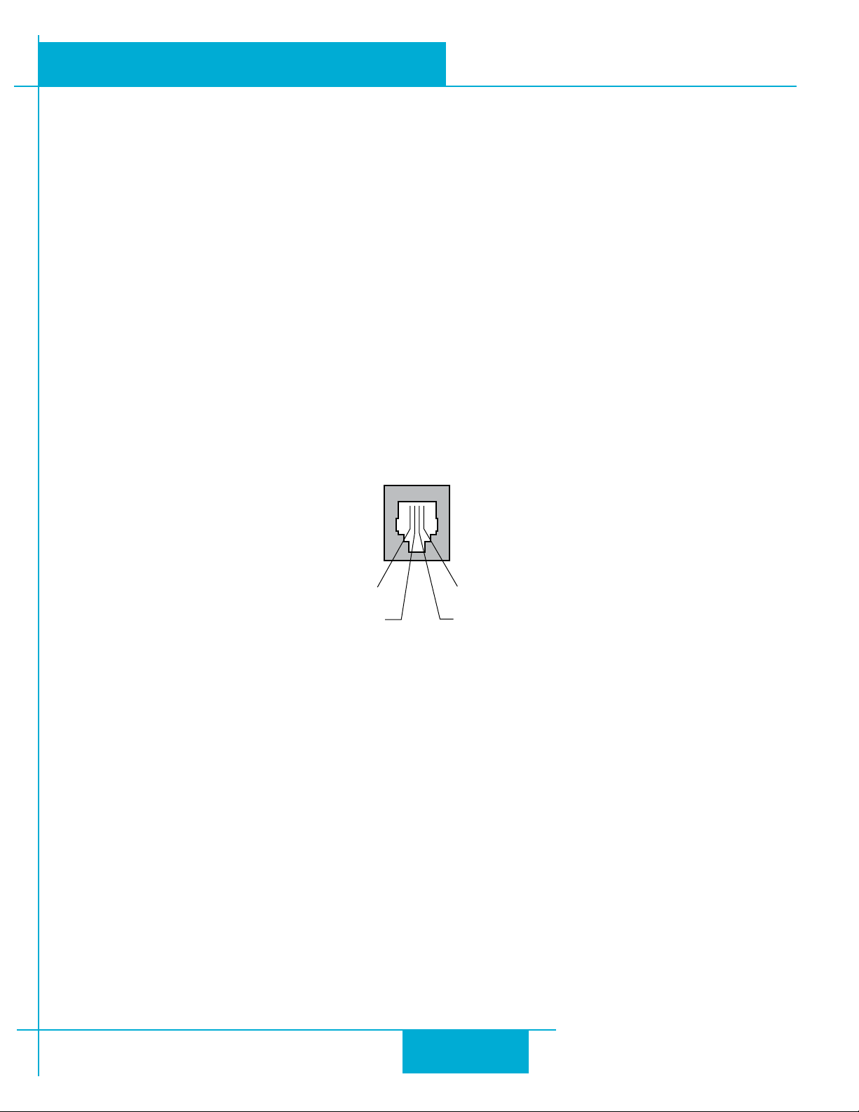
ground (to PC ground)
TX (to PC RX)
Pin Assignments of the RS-232 Port (RJ11 connector)
RX (to PC TX)
+5V Supply (for SiNet Hub)
e RS-232 circuitry does not have any extra electrical “hardening” and care should be taken when connecting to the RS-
232 port as hot plugging could result in circuit failure. If this is a concern the RS-422/485 version should be used.
Do not plug or unplug the RS-232 connection while power is applied to the drive. is is known as “hot
plugging” and should be avoided.
Connecting to a Host Using RS-422/485
RS-422/485 communication allows connection of more than one drive to a single host PC, PLC, HMI or other controller.
It also allows the communication cable to be long (more than 300 meters or 1000 feet). We recommend using Category
5 cable in low electrical-noise environments. Category 5 cable is widely used for computer networks, inexpensive, easily
obtained and certied for quality and data integrity. For electrically noisy environments we recommend twisted pair
cable with an overall shield and drain wire. Connect the drain wire at one end of the cable to earth ground..
RS-422/485 versions of the STM24 can be used with either four-wire or two-wire congurations. Both types of congurations can be used for point-to-point (i.e. one drive and one host) or multi-drop networks (one host and up to 32
drives).
13
Page 14
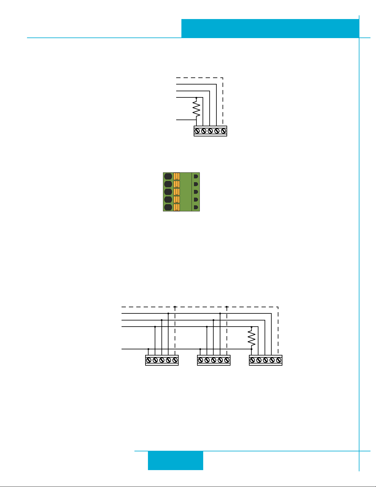
GND
TX–
TX+
RX–
RX+
920-0044D
10/7/2011
STM24 Hardware Manual
NOTE: To use the STM24 RS-422/485 version with the ST Congurator soware, the STM24 must be connected to the PC in the four-wire “point to point” conguration (see below) and congured one axis at a
time.
to Host GND
to Host Rx-
to Host Rx+
to Host Tx-
to Host Tx+
+Rx- +Tx- GND
STM24
RS-422/485 4–wire “Point to Point” Wiring
RS-422/485 Connector diagram
Four-Wire Conguration
Four-wire Systems utilize separate transmit and receive wires. One pair of wires must connect the host’s transmit signals to
each drive’s RX+ and RX- terminals. e other pair connects the drive’s TX+ and TX- terminals to the host’s receive signals.
A logic ground terminal is provided on each drive and can be used to keep all drives at the same ground potential.
is terminal connects internally to the DC power supply return (V-), so if all the drives on the RS-422/485 network are
powered from the same supply it is not necessary to connect the logic grounds. One drive’s GND terminal should still be
connected to the host computer ground.
to Host GND
to Host Rx-
to Host Rx+
to Host Tx-
120
to Host Tx+
+Rx- +Tx- GND +Rx- +Tx- GND +Rx- +Tx- GND
Drive 1 Drive 2 Drive n
RS-422/485 4–wire system
NOTE: a 120 ohm terminating resistor is required at the end of a four wire network.
NOTE: If the PC does not have an RS-422/485 serial port, a converter will be required.
14
Page 15
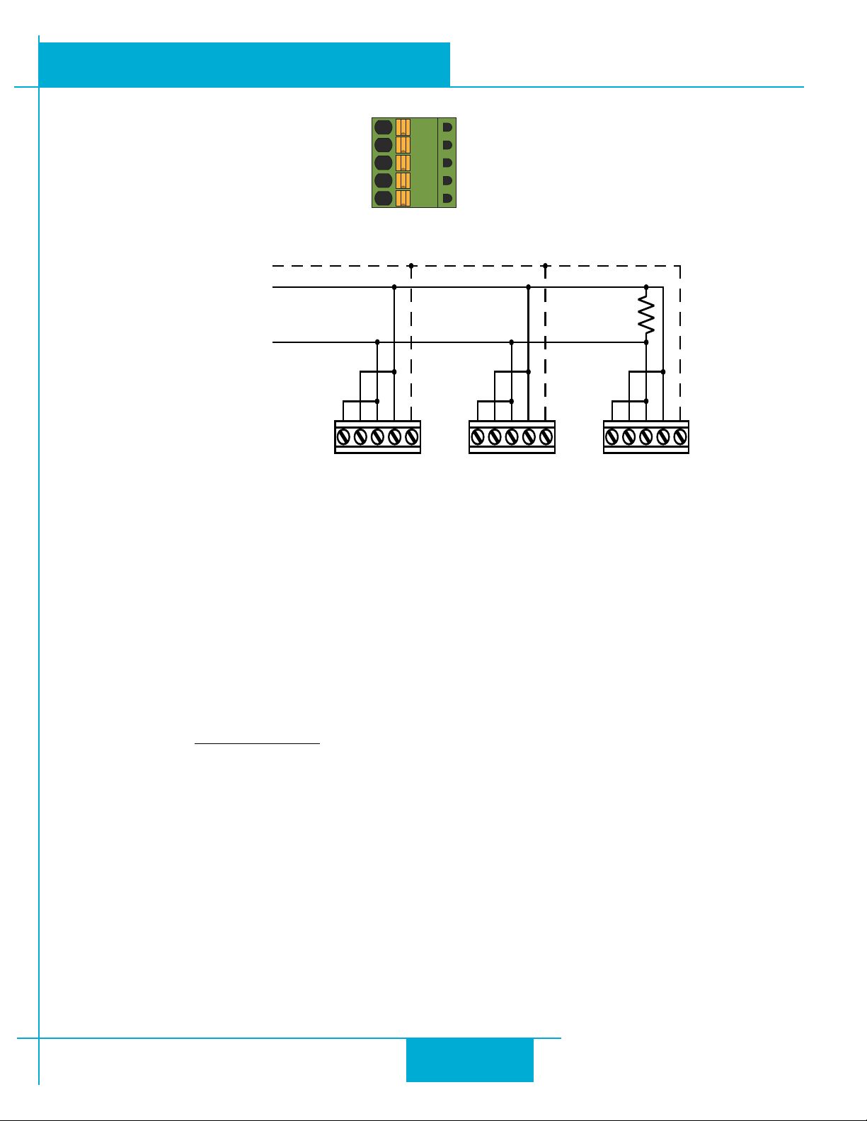
+Rx- +Tx- GND +Rx- +Tx- GND +Rx- +Tx- GND
to Host Tx+ (B)
to Host Tx- (A)
to Host GND
Drive 1 Drive 2 Drive n
120
GND
TX–
TX+
RX–
RX+
STM24 Hardware Manual
Two-Wire Conguration
920-0044D
10/7/2011
RS-422/485 Connector diagram
Transmit and receive on the same pair of wires can lead to trouble. e host must not only disable its transmier before
it can receive data, it must do so quickly, before a drive begins to answer a query. e STM24 includes a “transmit delay”
parameter that can be adjusted to compensate for a host that is slow to disable its transmier. is adjustment can be
made over the network using the TD command, or it can be set using the
set the transmit delay in a four-wire system.
NOTE: a 120 ohm terminating resistor is required at the end of the network
RS-232 to RS-485 2-wire Converter
Model 485-25E from Integrity Instruments (800-450-2001) works well for converting your PC’s RS-232 port to RS-485.
It comes with everything you need. Connect the adaptor’s “B” pin to the Drive+Motor’s TX+ and RX+ terminals. Connect
“A” to the drive’s TX- and RX- terminals.
Assigning RS-485 Addresses
Before wiring the entire system, you’ll need to connect each drive individually to the host computer so that a unique address can be assigned to each drive. Use the
Connect the drive to your PC and then launch the
have already congured your drive, then you should click the Upload buon so that the
those of your drive. Click on the Motion buon, then select the “SCL” operating mode. If you have a Q drive, you may
want to select “Q Programming”. Either way, you’ll see the RS-485 Address panel appear. Just click on the address character of your choice. You can use the numerals 0..9 or the special characters ! “ # $ % & ‘ ( ) * + , - . / : ; < = > ? @ . Just make
Typical RS-422/485 Two-Wire System
ST Congurator
ST Congurator™
ST Congurator™
soware that came with your drive for this purpose.
soware. Finally, apply power to your drive. If you
soware. It is not necessary to
ST Congurator™
seings match
15
Page 16
920-0044D
10/7/2011
sure that each drive on your network has a unique address. If you are using a 2-wire network, you may need to set the
Transmit Delay, too. 10 milliseconds works on the adapters we’ve tried. Once you’ve made your choices, click Download
to save the seings to your drive.
STM24 Hardware Manual
Connecting to an STM24 using USB
e USB-COMi-M (8500-003) from Applied Motion is an excellent choice for USB to serial conversion. It can be used
for all RS-232, RS-422 and RS-485 applications. e USB-COM-CBL from byterunner.com can be used for USB to RS-232
connection only. ese adapters use the FTDI chip set and are compatible with Windows XP and later, including 64 bit
versions.
Note: Prolic-based USB serial adapters do not work with Vista 64 or Windows 7 64 bit operating systems.
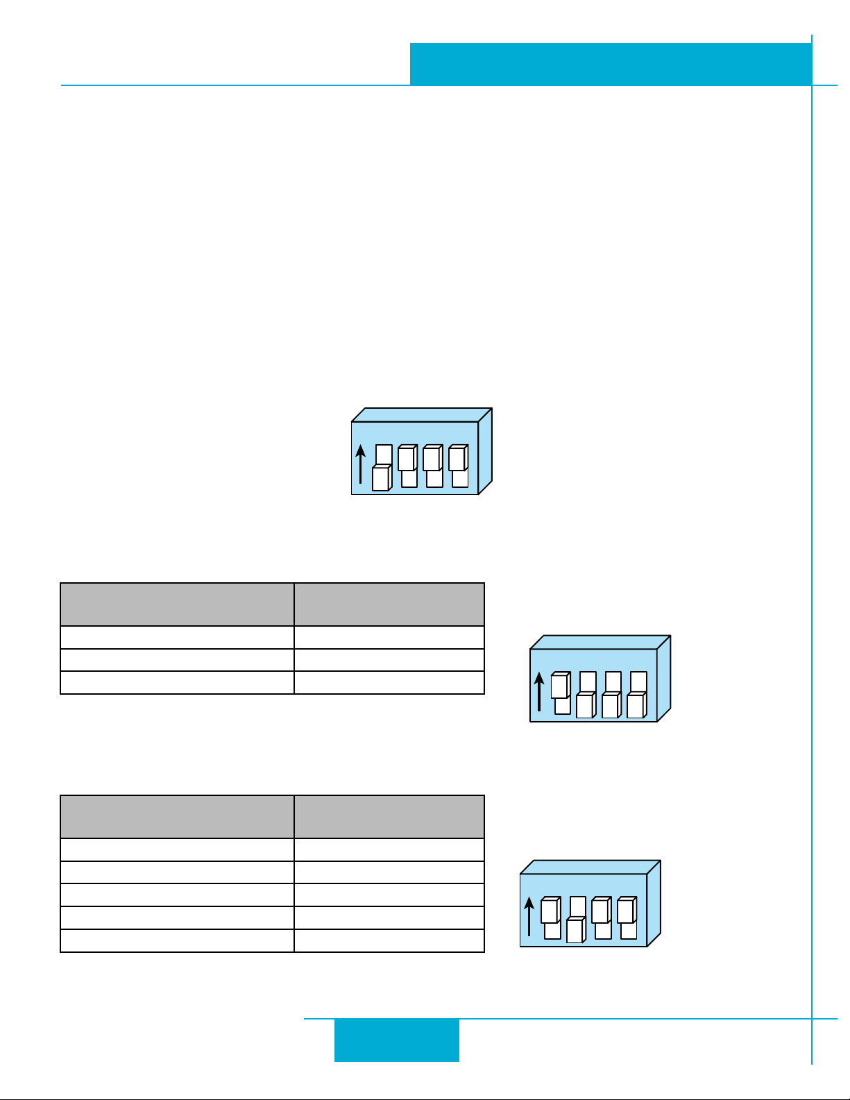
For RS-232 conversion using the USB-COMi-M (8500-003), use the DB9 connector and set the switches according to the
diagram below. e DB-9 connector is not used for RS-485.
RS-232
1ON2 3 4
USB-COMi-M (8500-003) Switch Seings
For RS-485 two wire systems, set the switches and make the connections to the STM24 according the diagrams below.
USB-COMi-M (8500-003) 6 pin
screw terminal connector
1 RX-, TX2 RX+, TX+
6 GND
For RS-485 four wire systems, set the switches and make the connections to the STM24 according the diagrams below.
USB-COMi-M (8500-003) 6 pin
screw terminal connector
1 RX2 RX+
3 TX+
4 TX6 GND
STM24 5 pin connector
STM24 5 pin connector
2 Wire
RS-485
1ON2 3 4
4 Wire
RS-485
1ON2 3 4
16
Page 17
920-0044D
STM24 Hardware Manual
10/7/2011
Inputs and Outputs (-SF and -QF)
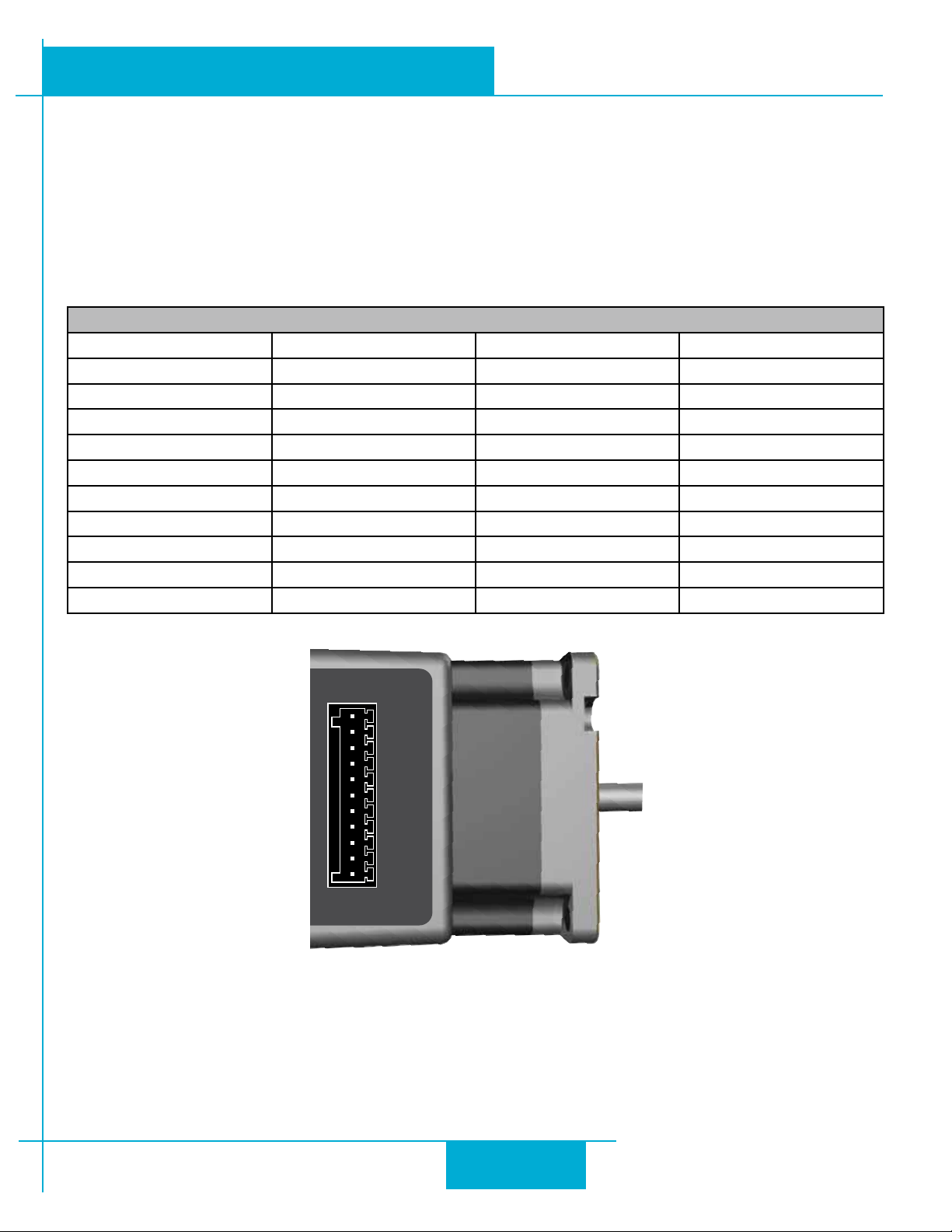
e STM24SF and STM24QF have four “ex I/O” points. Each can be congured as a digital input or a digital output. In
addition, pre-dened functions such as motor enable or fault output can be assigned, providing the exibility to handle a
diverse range of applications.
ST Congurator™
is used to set each ex I/O point as an input or output.
ST Congurator™
can also be used to assign
functions to each I/O point, or functions can be assigned “on the y” from SCL streaming commands or stored Q programs. Example connection diagrams can be found on the following pages.
I/O Functions (congure in software)
I/O 1 I/O 2 I/O 3 I/O 4
Step Input Direction Input
Jog CW Input Jog CCW Input Limit CW Input Limit CCW Input
Enable Input Alarm Reset Input Enable Input Alarm Reset Input
Start/Stop Input Change Speed Input
General Purpose Input General Purpose Input General Purpose Input General Purpose Input
Brake Output Brake Output Brake Output Brake Output
Fault Output Fault Output Fault Output Fault Output
Motion Output Motion Output Motion Output Motion Output
Tach Output Tach Output Tach Output Tach Output
General Purpose Output General Purpose Output General Purpose Output General Purpose Output
I/O 1+
I/O 1
I/O 2+
I/O 2
I/O 3+
I/O 3
I/O 4+
-
I/O 4
+5V
AIN
GND
STM24SF and STM24QF Connector Pin Diagram
17
Page 18
920-0044D
10/7/2011
STM24 Hardware Manual
inside drive
I/O+
I/O
-
I/O Connector
inside drive
I/O+
I/O
-
I/O Connector
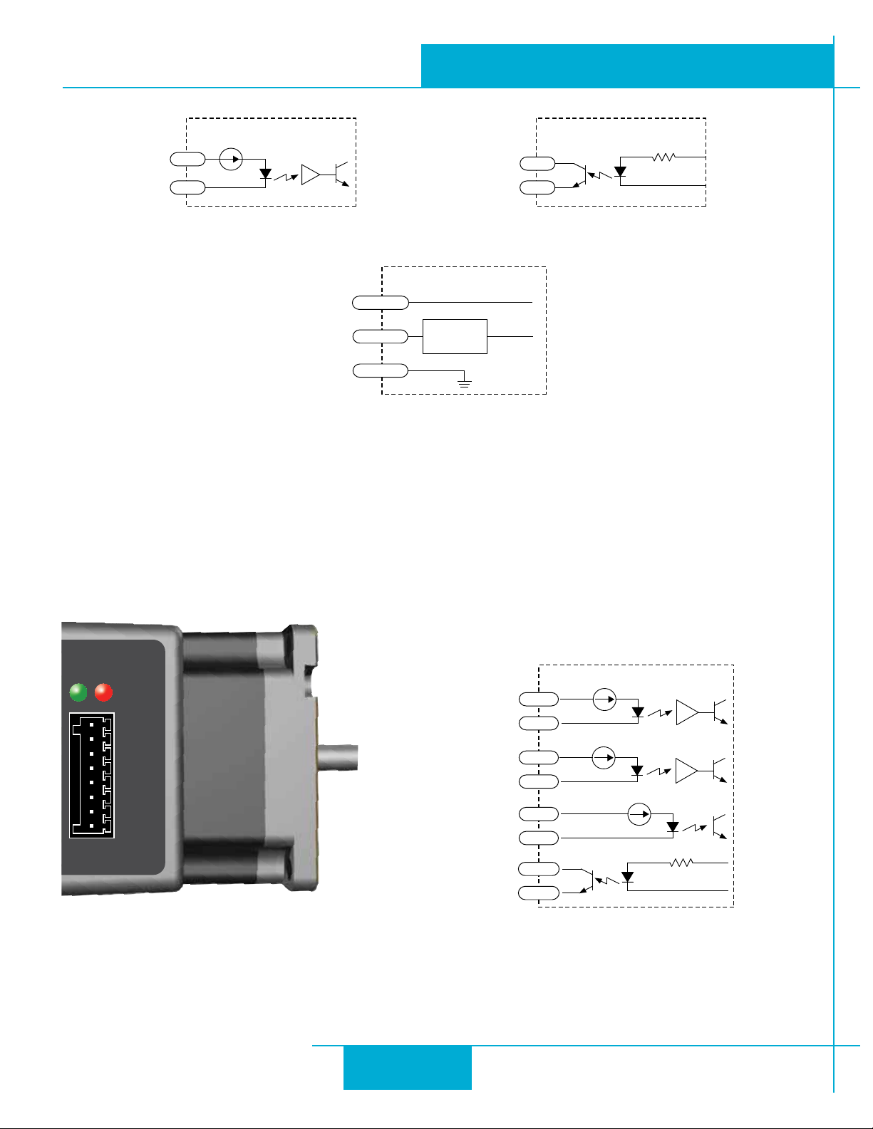
Equivalent Circuit: Flex I/O Point Set as Input Equivalent Circuit: Flex I/O Point Set as Output
inside drive
+5V
AIN
GND
I/O Conne ctor
Equivalent Circuit: Analog Input
50 mA max
Signal
Conditioning
Inputs and Outputs (-C)
e STM24C has three digital inputs and one digital output. e inputs can be used for end of travel limits and a
position sensor in support of the CANopen DSP402 homing modes, or as general purpose inputs to be read over the
CANopen network. e output has no predened purpose in the CANopen specs but can be used as a brake, fault,
motion or tach output, or it can be used as a general purpose output which can be opened or closed over the CANopen network. Example connection diagrams can be found on the following pages.
STATUS
IN1+
IN1
IN2+
IN2
IN3+
-
IN3
OUT+
OUT
IN1+
IN1
-
IN2+
IN2
-
I/O Conne ctor
IN3+
IN3
OUT+
OUT
-
-
-
inside STM24C
STM24C Connector Pin Diagram Equivalent Circuit
18
Page 19
920-0044D
STM24 Hardware Manual
10/7/2011
I/O Functions (congure in software)
IN1 IN2 IN3 OUT
Clockwise Limit Counterclockwise Limit Home Sensor Fault
General Purpose Input General Purpose Input Enable Input Brake
General Purpose Input Motion
Tach
General Purpose Output
Connecting Step and Direction Signals
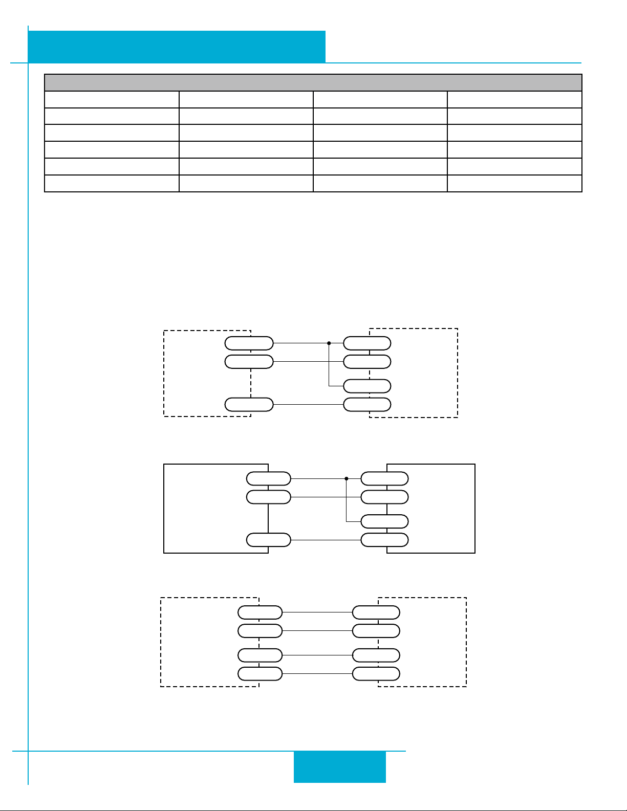
e STM24-QF and STM24-SF drives include two high-speed inputs that can accept 5 to 24 volt single-ended or dif-
ferential signals, up to 3 MHz. ese inputs can be connected to an external controller that provides step & direction (or
step CW and step CCW) command signals. You can also connect a master encoder to the high-speed inputs for “following” applications. Or you can use these inputs with Wait Input, If Input, Feed to Sensor, Seek Home and other SCL or Q
commands.
Connection diagrams follow.
Indexer
with
5-24 VDC
DIR I/O 2
I/O 2+
Sinking
Outputs
STEP I/O 1
I/O 1+
Connecting to indexer with Sinking Outputs
Indexer
COM
with
DIR I/O 2+
Sourcing
O utputs
STEP I/O 2+
Connecting to indexer with Sourcing Outputs
DIR+
I/O 2+
Indexer
with
DIR- I/O 2
Differential
Outputs
STEP+
STEP-
I/O 1+
I/O 1
-
-
I/O 2
I/O 1
-
-
STM24
-
STM24
-
STM24
Connecting to Indexer with Dierential Outputs
19
Page 20
STM24
Master
Encoder
DIR+
I/O 2+
DIR- I/O 2
-
I/O 1+
STEP-
STEP+
I/O 1
-
GND GND
920-0044D
10/7/2011
STM24 Hardware Manual
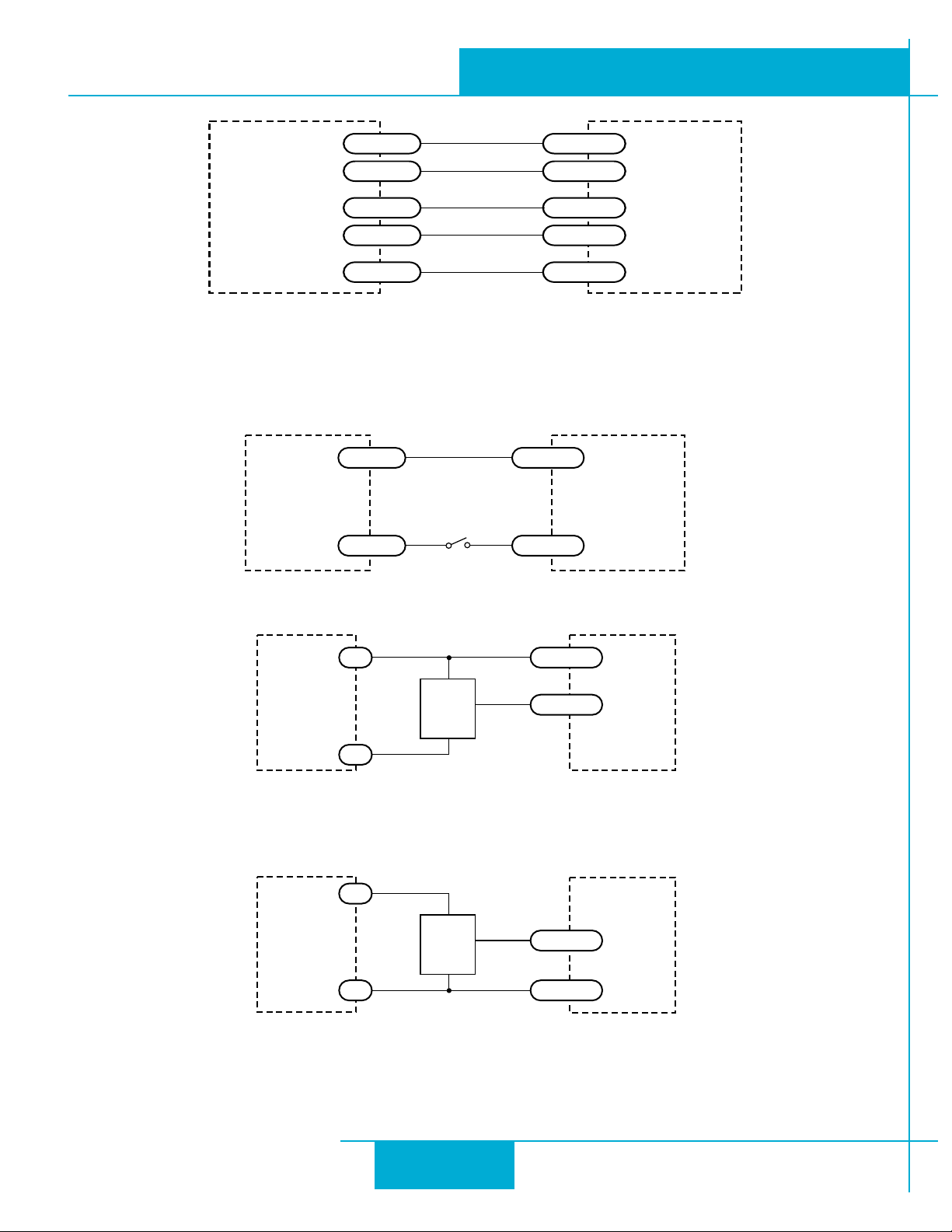
Wiring for Encoder Following
Connecting Other Signals
Note: If current is owing into or out of an input, the logic state of that input is low or closed. If no current is owing, or the input is not connected, the logic state is high or open.
+
I/O+
5-24 VDC
Power
Supply
Switch or Relay
(closed = logic Low)
-
I/O
STM24
-
Using Mechanical Switches
5-24 VDC
Power
Supply
+
+
NPN
Proximity
Sensor
output
–
-
I/O+
I/O
-
STM24
Connecting an NPN Type Proximity Sensor to an Input
(When prox sensor activates, input goes low).
5-24 VDC
Power
Supply
+
+
PNP
Proximity
Sensor
output
–
STM24
I/O+
-
Connecting an PNP Type Proximity Sensor to an Input
(When prox sensor activates, input goes low).
I/O
-
20
Page 21
920-0044D
STM24 Hardware Manual
10/7/2011
Analog Input
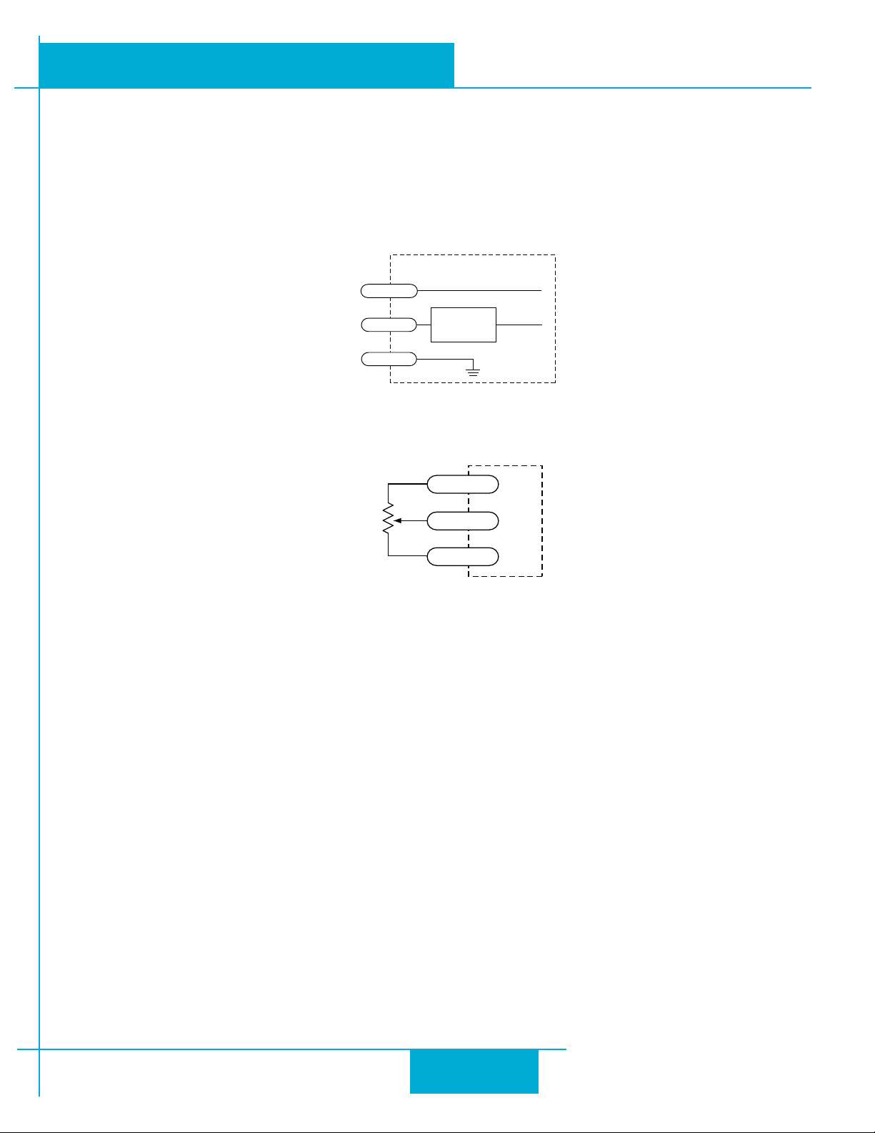
e STM24SF and STM24QF drives feature an analog input. e input can accept a signal range of 0 to 5 VDC. e
drive can be congured to operate at a speed or position that is proportional to the incoming analog signal. Use the
Congurator™
50ma output that can be used to power external devices such as potentiometers. It is not the most accurate supply for
reference; for more precise readings use an external supply that can provide the desired accuracy.
soware to set the signal range, oset, dead-band and lter frequency. e STM24 provides a +5VDC
inside drive
+5V
50 mA max
ST
Signal
Conditioning
I/O Conne ctor
AIN
GND
Analog Input Circuit
+5V OUT
cw
1-10k
pot
cc w
AIN
GND
Connecting a Potentiometer to the Analog Input
21
Page 22
920-0044D
10/7/2011
STM24 Hardware Manual
Programmable Output
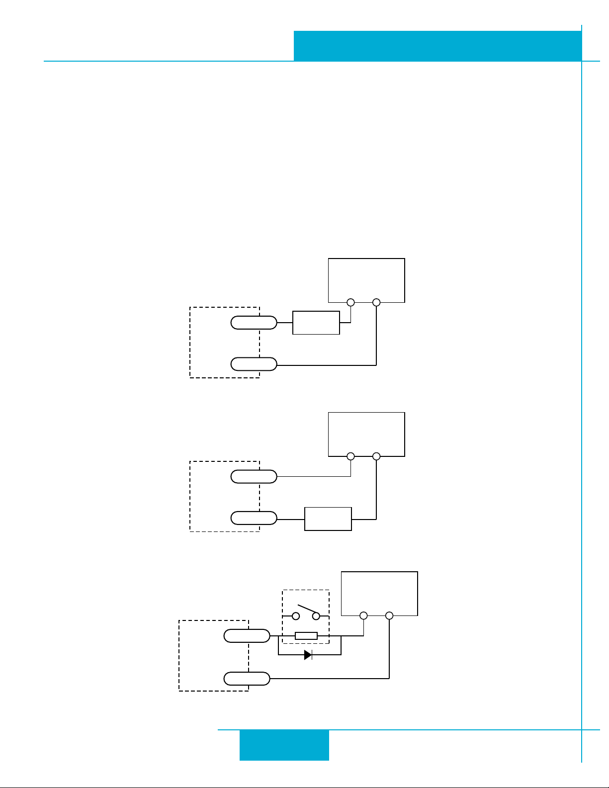
e STM24SF and STM24QF include four “ex I/O” points which can be individually congured to act as digital outputs.
e STM24C includes one dedicated digital output. Each output can be set to automatically control a motor brake, to
signal a fault condition, to indicate when the motor is moving or to provide an output frequency proportional to motor
speed (tach signal). An output can also be turned on and o by program instructions like Set Output. An output can be
used to drive LEDs, relays and the inputs of other electronic devices like PLCs and counters. e “OUT+” (collector) and
“OUT-” (emier) terminals of the transistor are available at the connector. is allows you to congure the output for cur-
rent sourcing or sinking.
Diagrams of various connection types follow.
Do not connect the output to more than 30VDC.
e current through the output terminal must not exceed 100mA.
5-24 VDC
Power Supply
+ –
OUT+
Load
STM24
OUT
-
Connecting a Sinking Output
OUT+
STM24
OUT
-
Load
Connecting a Sourcing Output
relay
5-24 VDC
Power Supply
+ –
5-24 VDC
Power Supply
STM24
OUT+
1N4935 suppression diode
OUT
-
Connecting a Relay
22
+ –
Page 23
Ø 38.1
60
47.14
Ø 8
Ø 7.5 Flat
4 - Ø 4.5
125.5±1
84
77
20.6
60
47.14
15
1.5
51
7
55
STM24X-3A
STM24 Hardware Manual
Reference Materials
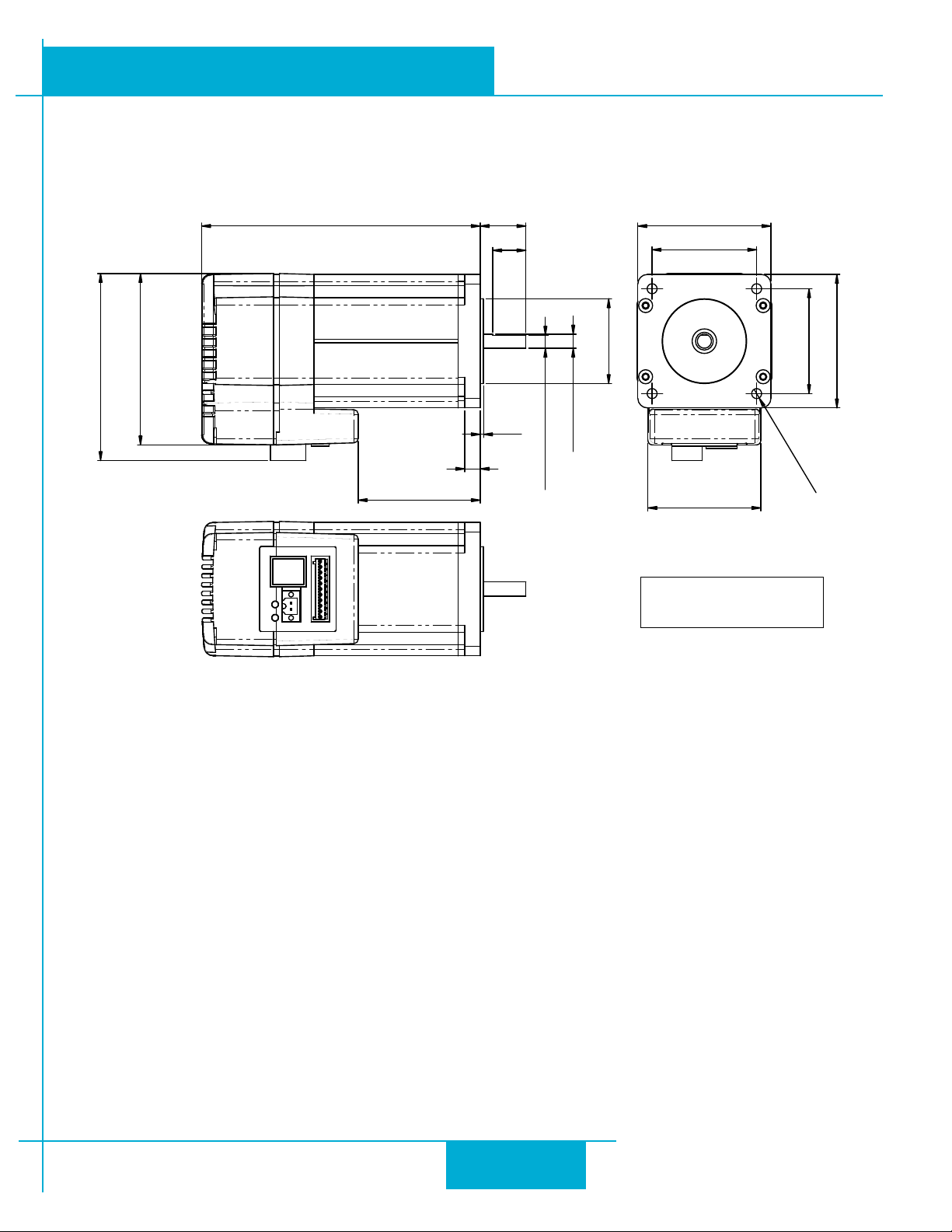
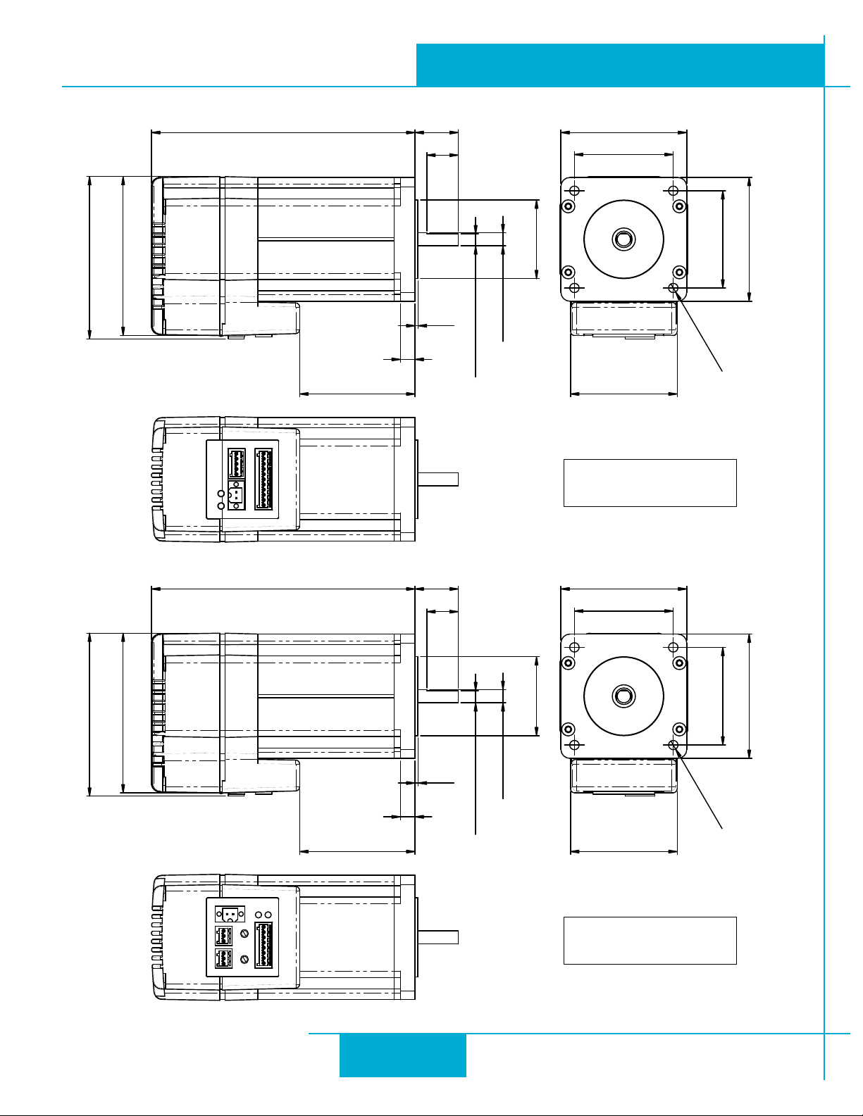
Mechanical Outline
920-0044D
10/7/2011
23
Page 24
Ø 38.1
60
47.14
Ø 8
Ø 7.5 Flat
4 - Ø 4.5
125.5±1
79
77
20.6
60
47.14
15
1.5
51
7
55
STM24X-3R
Ø 38.1
60
47.14
Ø 8
Ø 7.5 Flat
4 - Ø 4.5
125.5±1
79
77
20.6
60
47.14
15
1.5
51
7
55
STM24C-3C
4
3
2
1
0
F
E
D
1
B
A
9
8
7
6
5
2
1
0
9
8
7
6
5
4
3
920-0044D
10/7/2011
STM24 Hardware Manual
24
Page 25
920-0044D
STM24 Hardware Manual
10/7/2011
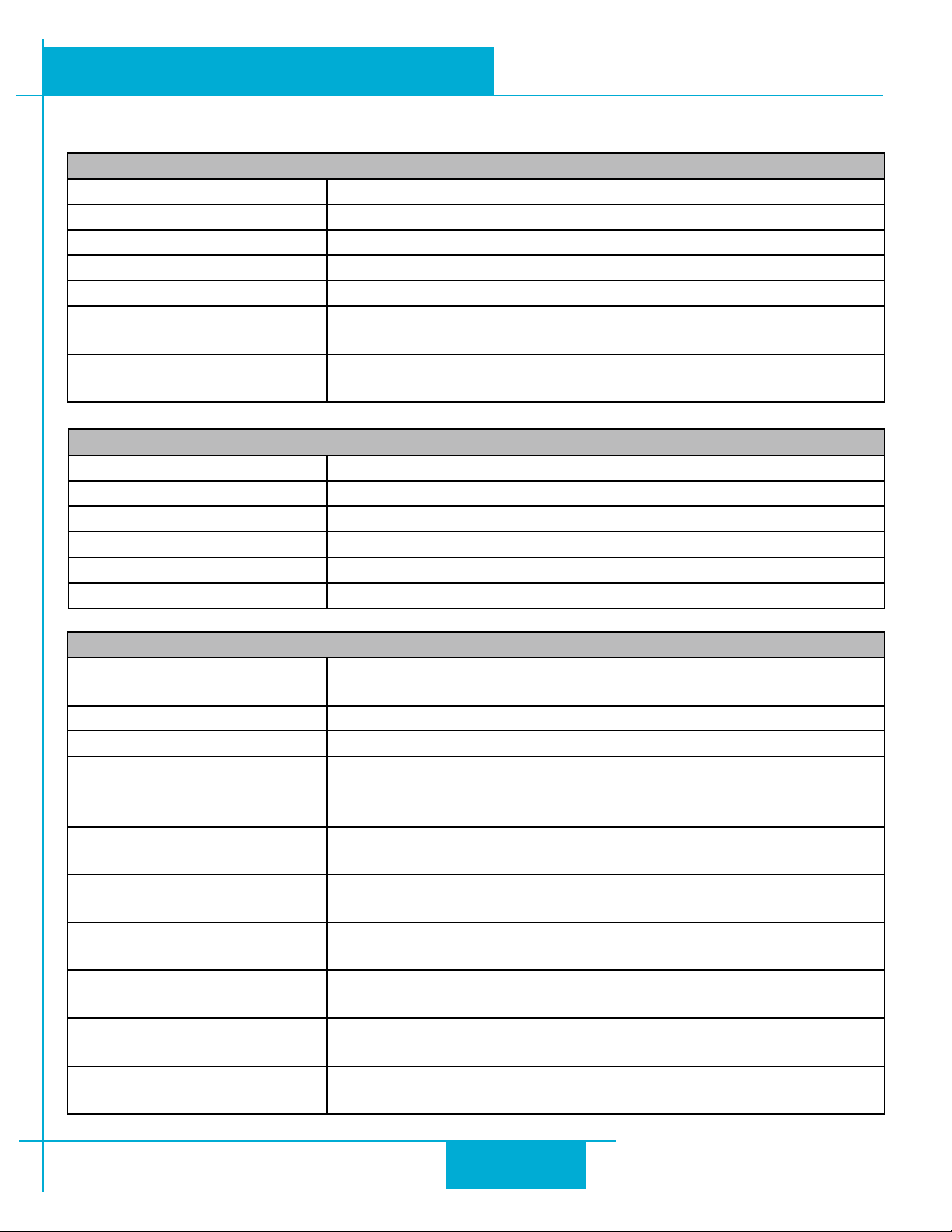
Technical Specications
POWER AMPLIFIER: All Models
AMPLIFIER TYPE Dual H-Bridge, 4 quadrant
CURRENT CONTROL 4 state PWM at 20 kHz
OUTPUT TORQUE 340 oz-in with suitable power supply
POWER SUPPLY External 12 - 70 VDC power supply required
INPUT VOLTAGE RANGE 10 - 75 min/max (nominal 12 - 70 VDC)
PROTECTION Over-voltage, under-voltage, over-temp, motor/wiring shorts (phase-
to-phase, phase-to-ground)
IDLE CURRENT REDUCTION Reduction range of 0 – 90% of running current after delay selectable
in milliseconds
PHYSICAL AND ENVIRONMENTAL
MASS 1.58 kg (56 oz)
2 (
ROTOR INERTIA 900 g-cm
AMBIENT TEMPERATURE 0 to 40°C (32 - 104°F) when mounted to suitable heatsink
HUMIDITY 90% non-condensing
AXIAL BEARING LOAD RATING 3.37 Lbs
RADIAL BEARING LOAD RATING 15.96 Lbs
1.27 x 10⁻² oz-in-sec2)
CONTROLLER: All Models
MICROSTEP RESOLUTION Software selectable from 200 to 51200 steps/rev in increments of 2
steps/rev
SPEED RANGE 0.00416 to 50 revolutions/second
DISTANCE RANGE Up to 10,000,000 revolutions (at 200 steps/rev)
ANTI-RESONANCE
(Electronic Damping)
TORQUE RIPPLE SMOOTHING Allows for ne adjustment of phase current waveform harmonic con-
AUTO SETUP Measures motor parameters and congures motor current control
SELF TEST Checks internal & external power supply voltages. Diagnoses open
MICROSTEP EMULATION Performs high resolution stepping by synthesizing ne microsteps
COMMAND SIGNAL SMOOTHING
ENCODER (OPTIONAL) 1000 lines (4000 counts/revolution). Index pulse mapped to input
Raises the system damping ratio to eliminate midrange instability
and allow stable operation throughout the speed range and improves
settling time.
tent to reduce low-speed torque ripple in the range 0.25 to 1.5 rps
and anti-resonance gain settings
motor phases and motor resistance changes >40%.
from coarse steps (Step & Direction mode only)
Software congurable ltering reduces jerk and excitation of extrane-
ous system resonances (Step & Direction mode only).
“0”.
25
Page 26
920-0044D
10/7/2011
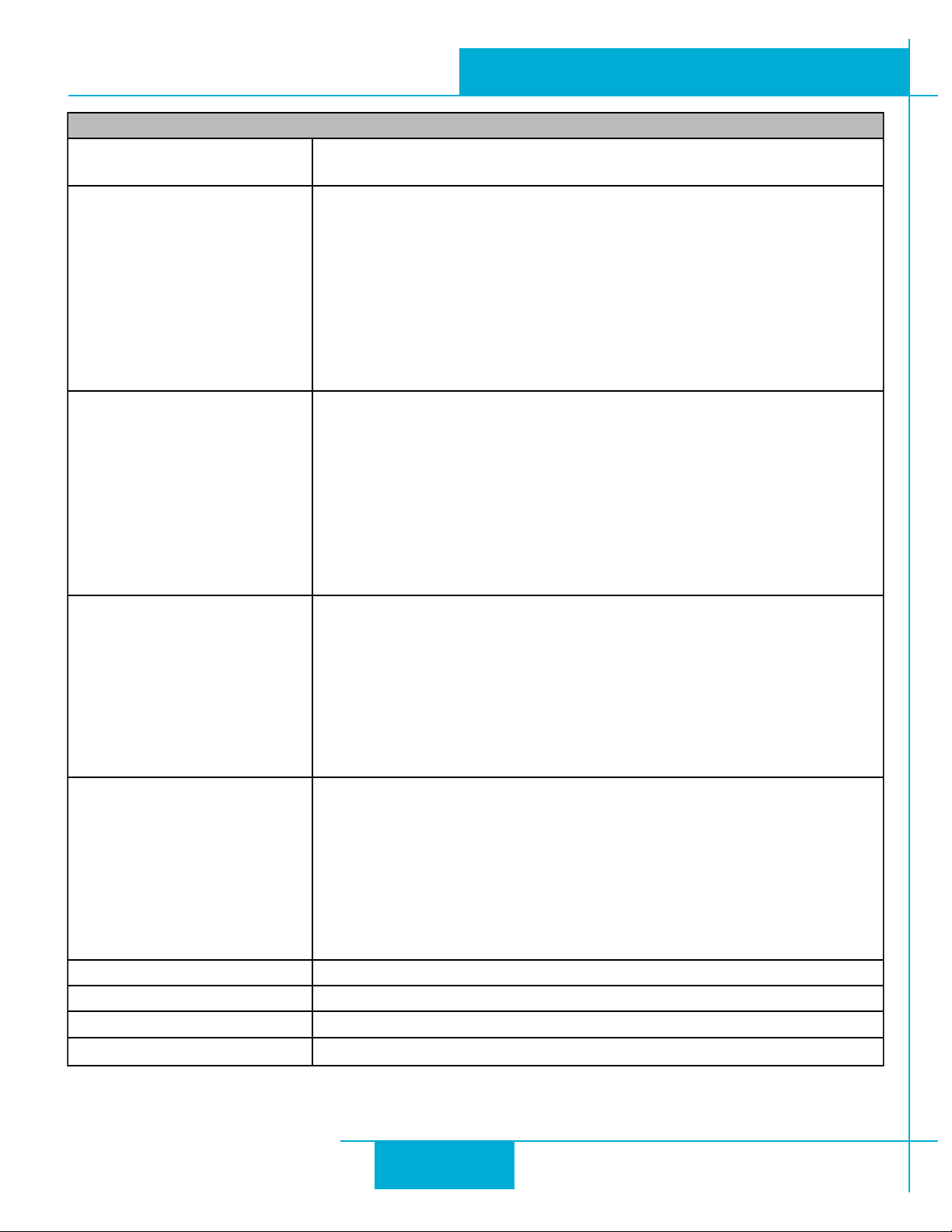
CONTROLLER: SF & QF Models
MODES OF OPERATION Step & direction, CW/CCW pulse, A/B quadrature, oscillator, joystick,
SCL streaming commands, stored programs (Q only).
I/O 1 (STEP) INPUT:
Optically isolated, 5-24 V, 8-12 mA. Minimum pulse width = 250 ns.
Maximum pulse frequency = 3 MHz. Adjustable bandwidth digital noise
rejection lter.
Function: Step, CW Step, A quadrature, CW jog, Start/stop (oscillator
mode), motor enable, general purpose Input.
OUTPUT:
Optically isolated, open emitter/collector, 30V, 40 mA max. 10 kHz
max. Function: fault, motion, tach, brake, general purpose
I/O 2 (DIR) INPUT:
Optically isolated, 5-24 V, 8-12 mA. Minimum pulse width = 250 ns.
Maximum pulse frequency = 3 MHz. Adjustable bandwidth digital
noise rejection lter. Function: direction (step & direction or oscillator
modes), CCW step, B quadrature, alarm reset, CCW jog, sensor, gen-
eral purpose input.
OUTPUT:
Optically isolated, open emitter/collector, 30V, 40 mA max. 10 kHz
max. Function: fault, motion, tach, brake, general purpose
I/O 3 INPUT:
Optically isolated, 5-24 V, 8-12 mA. Minimum pulse width = 250 ns.
Maximum pulse frequency = 3 MHz. Adjustable bandwidth digital noise
rejection lter. Function: speed change (oscillator mode), CW limit,
sensor, motor enable, general purpose input.
OUTPUT:
Optically isolated, open emitter/collector, 30V, 40 mA max. 10 kHz
max. Function: fault, motion, tach, brake, general purpose
I/O 4 INPUT:
Optically isolated, 5-24 V, 8-12 mA. Minimum pulse width = 250 ns.
Maximum pulse frequency = 3 MHz. Adjustable bandwidth digital noise
rejection lter.
Function: Alarm reset, CCW limit, sensor, general purpose input.
OUTPUT:
Optically isolated, open emitter/collector, 30V, 40 mA max. 10 kHz
max. Function: fault, motion, tach, brake, general purpose
ANALOG INPUT RANGE (AIN) 0 to 5VDC
ANALOG INPUT RESOLUTION 12 bits
COMMUNICATION RS-232 or RS-485
5 VOLT USER OUTPUT 4.8 to 5.0 VDC, 50 mA maximum
STM24 Hardware Manual
26
Page 27
920-0044D
STM24 Hardware Manual
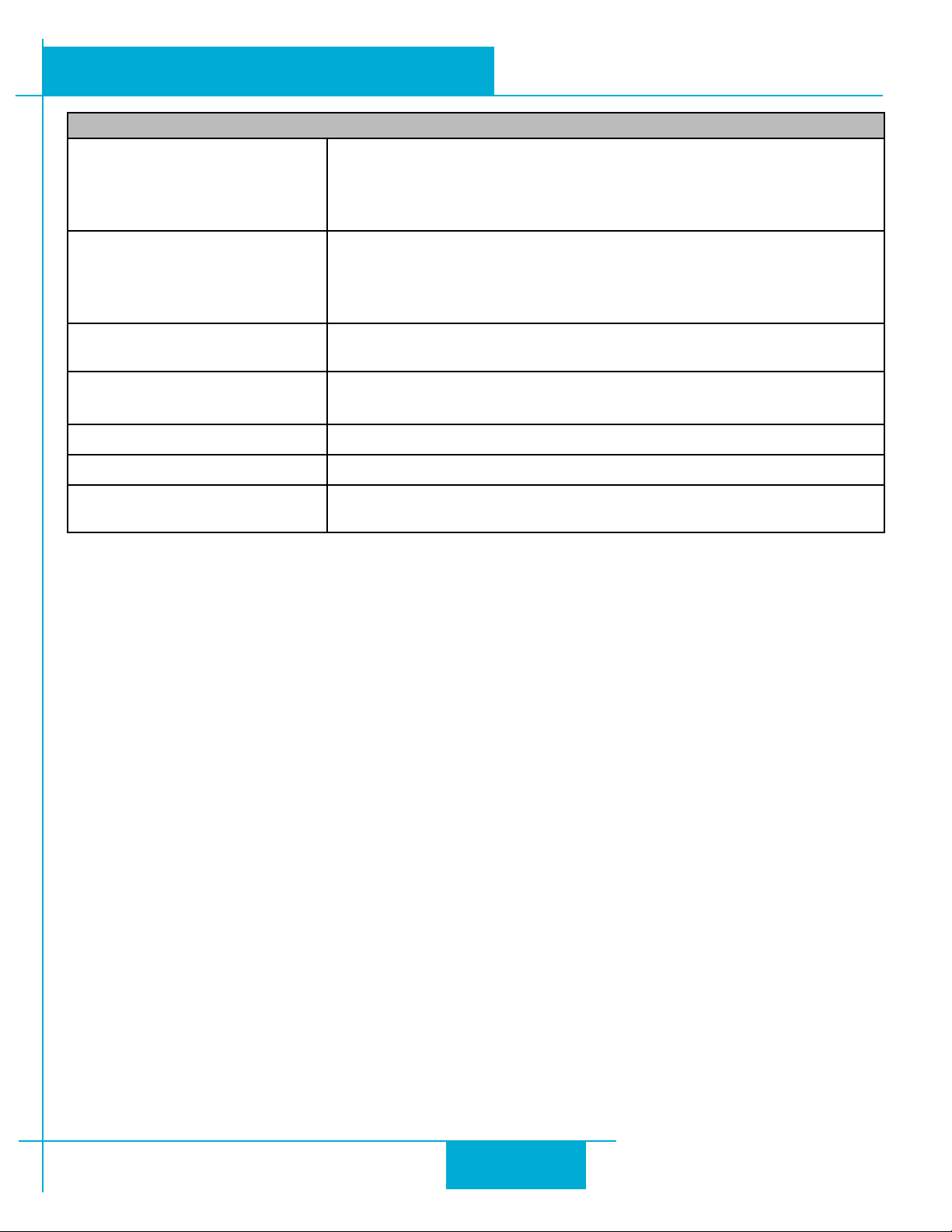
CONTROLLER: C Model
IN1 Optically isolated, 5-24 V, 8-12 mA. Minimum pulse width = 250 ns.
Maximum pulse frequency = 3 MHz. Adjustable bandwidth digital
noise rejection lter
Function: CW limit, general purpose input.
IN2 Optically isolated, 5-24 V, 8-12 mA. Minimum pulse width = 250 ns.
Maximum pulse frequency = 3 MHz. Adjustable bandwidth digital
noise rejection lter
Function: CCW limit, general purpose input.
IN3 Optically isolated, 5-24 V, 8-12 mA.
Function: home sensor, general purpose input.
OUT Optically isolated, 30V, 40mA MAX. open emitter/collector.
Function: fault, motion, alarm, tach or general purpose
COMMUNICATION INTERFACE CAN 2.0b (for CANopen network), RS-232 (for conguration)
CANOPEN CONFORMANCE DS301, DSP402
CANOPEN MOTION Homing, Prole Velocity, Prole Position (single set-point and set of
set-points)
10/7/2011
27
Page 28
STM24X
-
3
V24V48V70V
50
920-0044D
10/7/2011
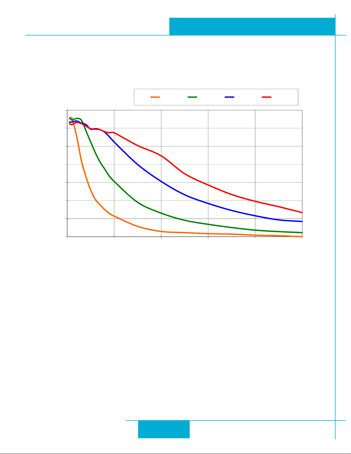
Torque-Speed Curves
Note: all torque curves were measured at 20,000 steps/rev.
12
6A/phase
350
300
250
200
oz-in
150
STM24 Hardware Manual
100
0
0 10 20 30 40 50
rps
28
Page 29
920-0044D
STM24 Hardware Manual
Drive/Motor Heating
Step motors convert electrical power from the driver into mechanical power to move a load. Because step motors are
not perfectly ecient, some of the electrical power turns into heat on its way through the motor. is heating is not so
much dependent on the load being driven but rather the motor speed and power supply voltage. ere are certain
combinations of speed and voltage at which a motor cannot be continuously operated without damage.
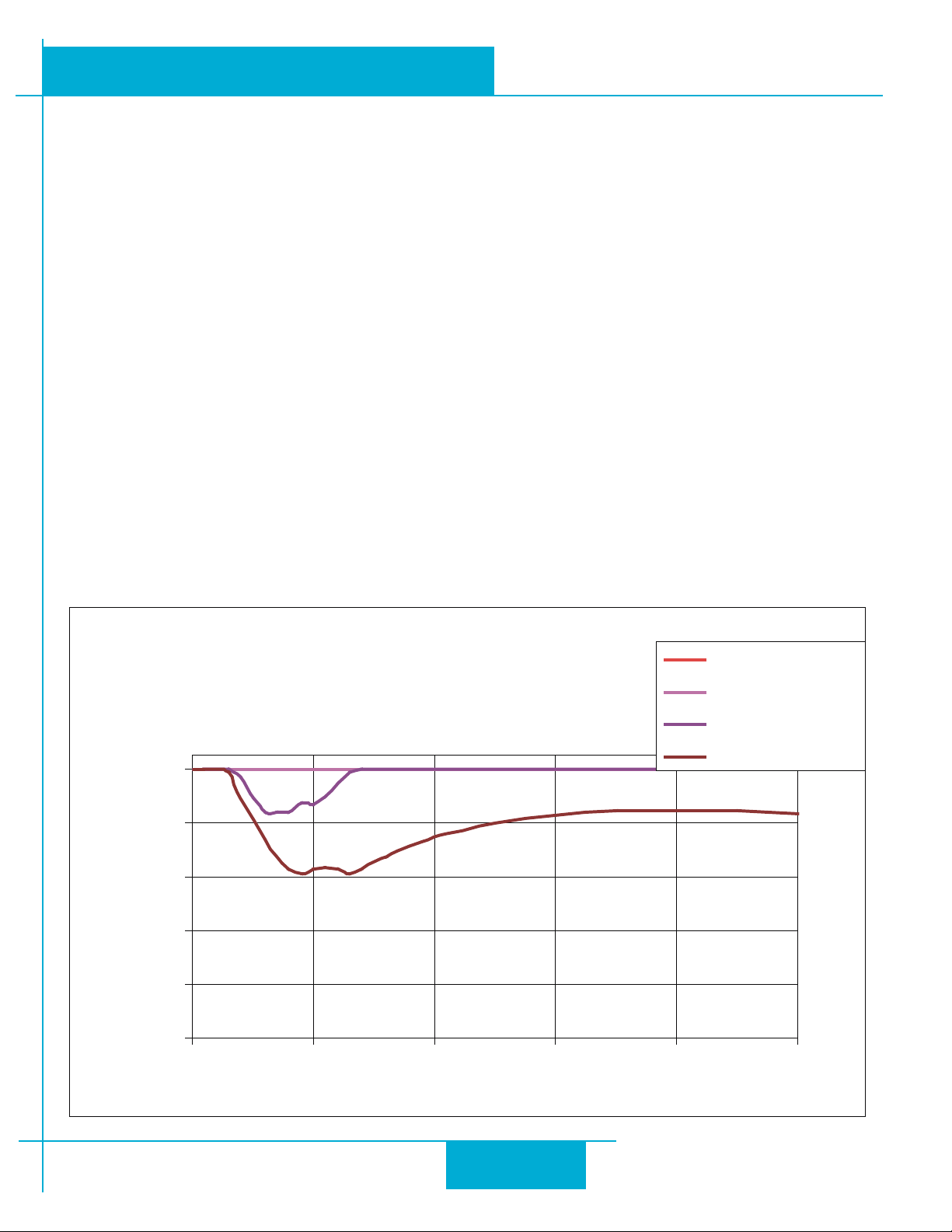
We have characterized the STM24 in our lab and provided curves showing the maximum duty cycle versus speed for
commonly used power supply voltages. Please refer to these curves when planning your application.
Please also keep in mind that a step motor typically reaches maximum temperature aer 30 to 45 minutes of operation.
If you run the motor for one minute then let it sit idle for one minute, that is a 50% duty cycle. Five minutes on and ve
minutes o is also 50% duty. However, one hour on and one hour o has the eect of 100% duty because during the
rst hour the motor will reach full (and possibly excessive) temperature.
e actual temperature of the motor depends on how much heat is conducted, convected or radiated out of it. Our
measurements were made in a 40°C (104°F) environment with the motor mounted to an aluminum plate sized to provide
a surface area consistent with the motor power dissipation. Your results may vary.
10/7/2011
STM24X-3 Max Duty Cycle vs Speed
6A/phase, 40°C Ambient
Mounted on a 162 x 162 x 6 (mm)
Aluminum Plate
100
80
e l c y C y t u D %
60
40
20
0
0 10 20 30 40 50
Speed (RPS)
12V Duty Cycle
24V Duty Cycle
48V Duty Cycle
65V Duty Cycle
29
Page 30
920-0044D
10/7/2011
STM24 Hardware Manual
Mating Connectors and Accessories
Connector Part Number - Manufacturer
DC Power (2-position, screw terminal) 1615780000 - Weidmuller
I/O (11-position, spring cage) 1881419 - Phoenix
RS-485 (5-position, spring cage) 1881354 - Phoenix
Accessories
Serial programming cable for programming units with RS-232 ports (STM24x-xAx): P/N 3004-189
USB serial adapter with one RS-232 port and one RS-485 port for programming all units: P/N 8500-003
DC power supplies:
24 V, 150 W switching power supply, P/N PS150A24
48 V, 320 W switching power supply, P/N PS320A48
Regeneration clamp for use with high inertial loads: RC-050
Note: Prolic-based USB serial adapters do not work with Vista 64 or Windows 7 64 bit operating systems.
Suggested adapters are Applied Motion Products USB-COMi-M (8500-003) or Byterunner USB-COM-CBL.
30
Page 31
920-0044D
STM24 Hardware Manual
10/7/2011
LED Error Codes
Status LED STM
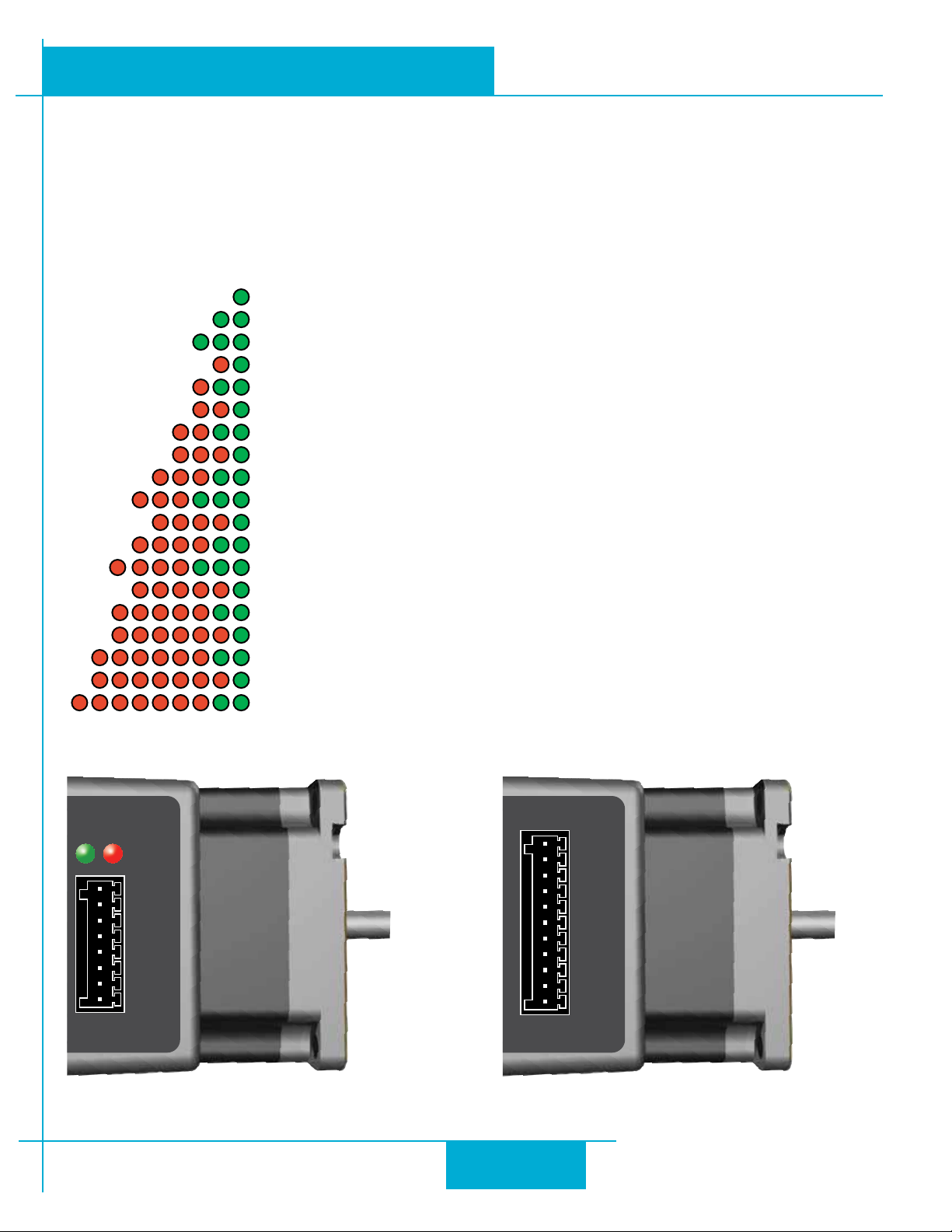
e STM drive+motor includes red and green LEDs to indicate status. When the motor is enabled, the green LED ashes
slowly. When the green LED is solid, the motor is disabled. Errors are indicated by combinations of red and green
“ashes” as follows:
Code Error
solid green no alarm, motor disabled
flashing green no alarm, motor enabled
fast green Q program running
1 red, 1 green motor stall (optional encoder only)
1 red, 2 green move attempted while drive disabled
2 red, 1 green ccw limit
2 red, 2 green cw limit
3 red, 1 green drive overheating
3 red, 2 green internal voltage out of range
3 red, 3 green blank Q segment
4 red, 1 green power supply overvoltage
4 red, 2 green power supply undervoltage
4 red, 3 green flash memory backup error
5 red, 1 green over current / short circuit
5 red, 2 green I/O occupied
6 red, 1 green open motor winding
6 red, 2 green bad encoder signal (optional encoder only)
7 red, 1 green serial communication error
7 red, 2 green flash memory error
STATUS
IN1+
-
IN1
IN2+
IN2
-
IN3+
-
IN3
OUT+
-
OUT
STM24C Connector Pin Diagram STM24SF & STM24QF Connector Pin Diagram
I/O 1+
I/O 1
I/O 2+
I/O 2
I/O 3+
I/O 3
I/O 4+
I/O 4
+5V
AIN
GND
-
-
-
-
31
Page 32
920-0044D
Re-Order from
omegamation.com
Omegamation
TM
1-888-55-OMEGA
1-888-55-66342
1-888-55-66342
10/7/2011
Contacting Applied Motion Products
Corporate Headquarters
404 Westridge Drive
Watsonville, CA 95076
(831) 761-6555
fax (831) 761-6544
web www.applied-motion.com
[email protected]
STM24 Hardware Manual
32
 Loading...