

Page 1
67
Re-Order from
omegamation.com
Omegamation
TM
1-888-55-OMEGA
1-888-55-66342
1-888-55-66342
• ST5-Q • ST10-Q
• ST5-Si • ST10-Si
34%0-/4/2
$2)6%2
ijKCg
6
6
6
6
3ERIAL.O
!
!
,%$#ODES
!
!
'2'REEN
2$2ED
-/4/2$)3!",%$ 3/,)$'2%%.
-/4/2%.!",%$ '2'2'2
-/4/234!,, '22$
##7,)-)4 '22$
#7,)-)4 '22$
#!.4-/6%$)3!",%$'22$
$2)6%/6%24%-0 '22$
6/,4!'%()'( '22$
6/,4!'%,/7 '22$
/6%2#522%.4 '22$
-/4/2/(-3 '22$
/0%.-/4/20(!3% '22$
"!$%.#/$%23)'.!, '22$
"
"
"
"
#/--%22/2 '22$
nNEYYmb_c_jC
nNEYYmb_c_jA
nMEYmb_c_jC
nMEYmb_c_jA
oJC
AKlekj
oJA
]dZ
oYecced
oIE\Wkbj
oHEcej_ed
oGEXhWa[
]dZ
nGEij[fA
nGEij[fC
nHEZ_hA
nHEZ_hC
nYecced
nIE[dWXb[
nJEWbWhch[i[j
nKEYm`e]
nLEYYm`e]
WdWbe]_dH
WdWbe]_dG
920-0004 Rev. A4
5/707
Page 2

920-0004 Rev. A4
5/707
ST5/10-Si,-Q Hardware manualST5/10-Si,-Q Hardware manual
ST5/10-Si,-Q Hardware manual
ST5/10-Si,-Q Hardware manualST5/10-Si,-Q Hardware manual
Contents
Introduction .............................................................................................................................................................................. 3
Features .................................................................................................................................................................................... 3
Block Diagrams ........................................................................................................................................................................ 4
Getting Started .......................................................................................................................................................................... 5
Connecting to the PC using RS-232 ......................................................................................................................................... 7
Connecting to a host using RS-485 option card ....................................................................................................................... 8
RS-232 to RS-485 4-wire Converter .................................................................................................................................. 8
RS-232 to RS-485 2-wire Converter .................................................................................................................................. 9
Converting USB to RS-485 ................................................................................................................................................ 9
Connecting the Power Supply ................................................................................................................................................ 11
Connecting the Motor ............................................................................................................................................................. 12
Connecting an Encoder (Requires the optional Encoder Feedback Card) ................................................................................ 13
Connecting Input Signals ....................................................................................................................................................... 14
Connector Pin Diagram ................................................................................................................................................... 14
High Speed Digital Inputs ................................................................................................................................................ 15
Using High Speed Inputs with 12-24 Volt Signals .................................................................................................... 16
Connecting to PLC with Sourcing (PNP) Outputs ..................................................................................................... 16
Using Mechanical Switches at 24 Volts .................................................................................................................... 17
Connecting to PLC with Sinking (NPN) Outputs ....................................................................................................... 17
Other Digital Inputs .......................................................................................................................................................... 18
Single Ended Inputs .................................................................................................................................................. 18
What is COM?........................................................................................................................................................... 18
Connecting Limit Switches .............................................................................................................................................. 20
Wiring a Mechanical Limit Switch ............................................................................................................................. 21
Wiring a Limit Sensor ............................................................................................................................................... 21
Analog Inputs .................................................................................................................................................................. 22
Programmable Outputs ........................................................................................................................................................... 23
Sinking Output ................................................................................................................................................................. 23
Sourcing Output .............................................................................................................................................................. 24
Driving a Relay ................................................................................................................................................................ 24
Choosing a Power Supply ...................................................................................................................................................... 25
Current ............................................................................................................................................................................ 25
Recommended Motors............................................................................................................................................................ 26
Torque-Speed Curves ............................................................................................................................................................. 26
Motor Heating ........................................................................................................................................................................ 29
Mounting the Drive ................................................................................................................................................................. 34
Mechanical Outline ................................................................................................................................................................. 34
Technical Specifications ......................................................................................................................................................... 35
Mating Connectors and Accessories ....................................................................................................................................... 35
Alarm Codes ........................................................................................................................................................................... 37
Connector Diagrams ............................................................................................................................................................... 37
22
2
22
Page 3

920-0004 Rev. A4
ST5/10-Si,-Q Hardware manualST5/10-Si,-Q Hardware manual
ST5/10-Si,-Q Hardware manual
ST5/10-Si,-Q Hardware manualST5/10-Si,-Q Hardware manual
Introduction
Thank you for selecting an Applied Motion Products motor control. We hope our dedication to
performance, quality and economy will make your motion control project successful.
If there's anything we can do to improve our products or help you use them better, please call or
fax. We'd like to hear from you. Our phone number is (800) 525-1609, or you can reach us by fax
at (831) 761-6544. You can also email [email protected].
Features
• Programmable, microstepping digital step motor driver in compact package
• ST5 operates from a 24 to 48 volt DC power supply
• ST10 operates from a 24 to 80 volt DC power supply
• Operates in velocity or position mode
• Accepts analog signals, digital signals and RS-232 serial commands
• Optional RS-422/485 communication
• Optional encoder feedback
• ST5 provides motor current up to 5 amps/phase (peak of sine)
• ST10 provides motor current up to 10 amps/phase (peak of sine)
• Eight optically isolated digital inputs
• Four optically isolated digital outputs
• Two ±10 volt analog inputs for speed and position control. Can also be configured for 0 to
10V, ±5V or 0 to 5V signal ranges.
5/707
33
3
33
Page 4
920-0004 Rev. A4
5/707
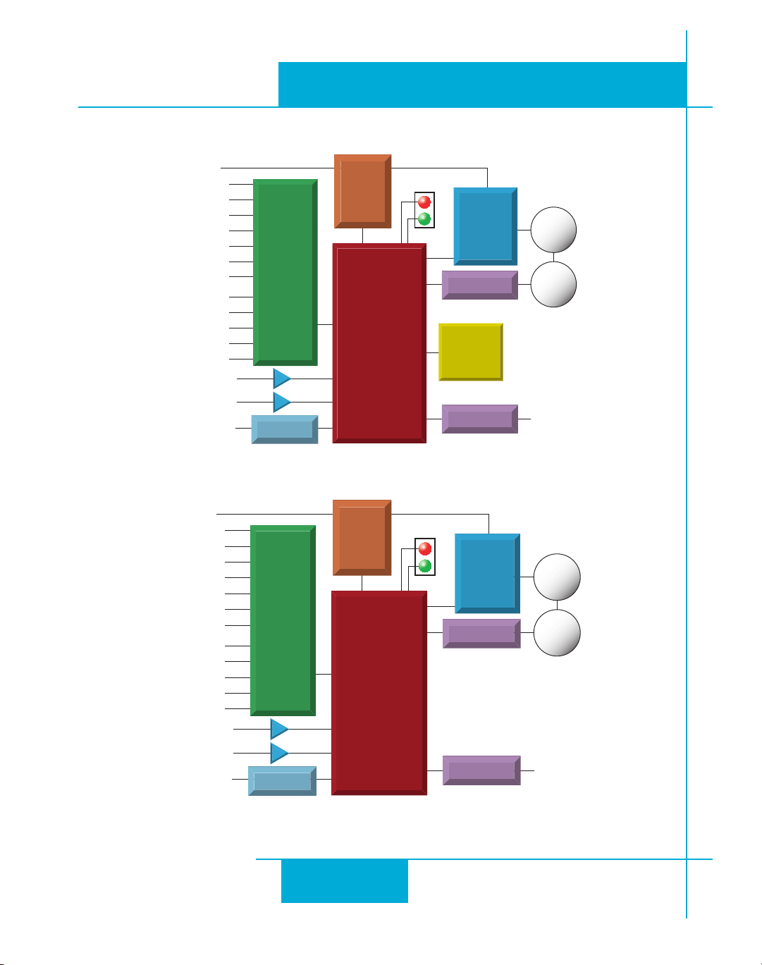
Block Diagrams
ST5/10-Si,-Q Hardware manualST5/10-Si,-Q Hardware manual
ST5/10-Si,-Q Hardware manual
ST5/10-Si,-Q Hardware manualST5/10-Si,-Q Hardware manual
6$#
).0548
).0548
).0548
).0548
).0548
).0548
8#7,)-
8##7,)-
/540549
/540549
/540549
/540549
!.!,/').
!.!,/').
TO0#--)
6$#FOR34
6$#
).0548
).0548
).0548
).0548
).0548
).0548
8#7,)-
8##7,)-
/540549
/540549
/540549
/540549
!.!,/').
!.!,/').
TO0#--)
)NTERNAL
/PTICAL
)SOLATION
23
ST5-Si and ST10-Si
)NTERNAL
/PTICAL
)SOLATION
23
,OGIC
3UPPLY
Zif
,OGIC
3UPPLY
Zif
3TATUS
3TATUS
-/3&%4
07-
0OWER
!MPLIFIER
/PTION#ARD
iÔ
#HIP
/PTION#ARD
-/3&%4
07-
0OWER
!MPLIFIER
/PTION#ARD
/PTION#ARD
MOTOR
ENCODER
23
MOTOR
ENCODER
23
6$#FOR34
ST5-Q and ST10-Q
44
4
44
Page 5

920-0004 Rev. A4
ST5/10-Si,-Q Hardware manualST5/10-Si,-Q Hardware manual
ST5/10-Si,-Q Hardware manual
ST5/10-Si,-Q Hardware manualST5/10-Si,-Q Hardware manual
Getting Started
This manual describes the use of four different drive models. What you need to know and what
you must have depends on the drive model. For all models, you’ll need the following:
• a 24-48 volt DC power supply. (24 - 80VDC for ST10 models). Please read the
section entitled
• a compatible step motor (see page 25)
• a small flat blade screwdriver for tightening the connectors (included).
• a personal computer running Microsoft Windows 98, 2000, NT, Me or XP.
• The Applied Motion CD (included)
• An Applied Motion programming cable (included)
If you’ve never used an ST drive beforeIf you’ve never used an ST drive before
If you’ve never used an ST drive before
If you’ve never used an ST drive beforeIf you’ve never used an ST drive before
software before you try to deploy the system in your application. We strongly recommend the
following:
Choosing a Power Supply
you’ll need to get familiar with the drive and the set up
for help in choosing the right power supply.
5/707
1. For -Q drives, install the
CD. For
2. Launch the software by clicking Start...Programs...Applied Motion...
3. Connect the drive to your PC using the programming cable.
4. Connect the drive to the power supply.
5. Connect the drive to the motor.
6. Apply power to the drive.
7. The software will recognize your drive, display the model and firmware version and be ready for
action.
Si™
models, use the
ST Configurator™
Si Programmer™
and
Q Programmer™
software for configuration and programming.
software applications from the
55
5
55
Page 6
920-0004 Rev. A4
ST5/10-Si,-Q Hardware manualST5/10-Si,-Q Hardware manual
ST5/10-Si,-Q Hardware manual
5/707
ST5/10-Si,-Q Hardware manualST5/10-Si,-Q Hardware manual
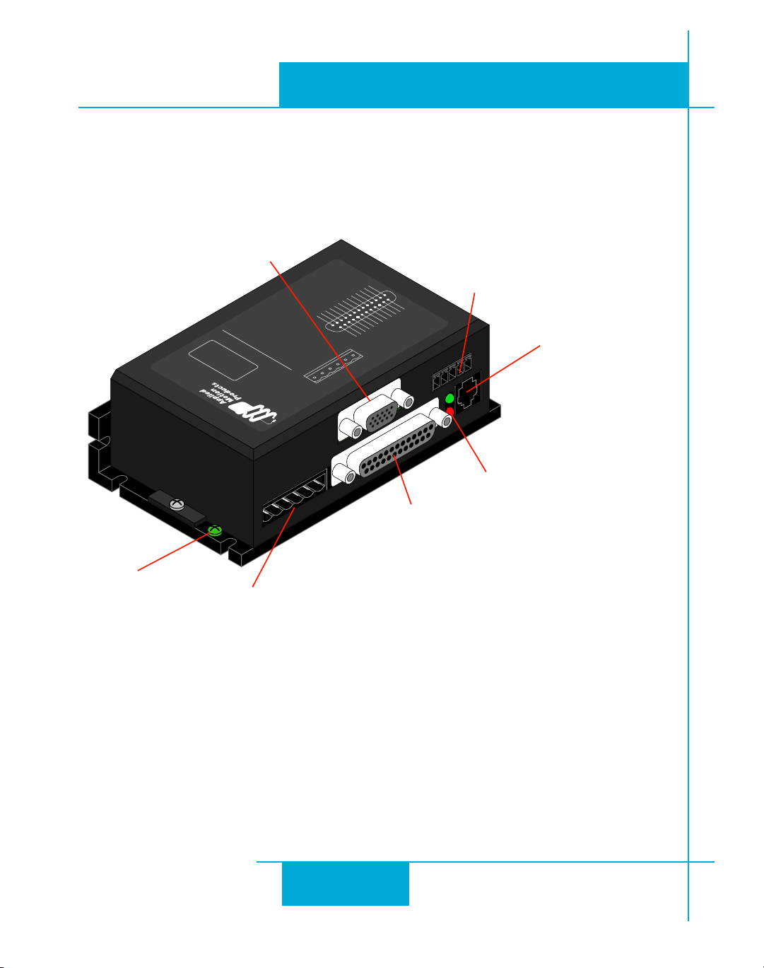
The connectors and other points of interest are illustrated below. Depending on your drive model
and application, you’ll need to make connections to various parts of the drive. These are detailed
later in the manual.
($CONNECTOR
s
OPTIONALENCODERFEEDBACK
2$2ED
'2'REEN
3ERIAL.O
ijKCg
nGEij[fA
]dZ
6/,4!'%,/7 '22$
6/,4!'%()'( '22$
$2)6%/6%24%-0 '22$
#!.4-/6%$)3!",%$'22$
#7,)-)4 '22$
##7,)-)4 '22$
-/4/234!,, '22$
-/4/2%.!",%$ '2'2'2
-/4/2$)3!",%$ 3/,)$'2%%.
,%$#ODES
$2)6%2
34%0-/4/2
nHEZ_hA
nGEij[fC
/6%2#522%.4 '22$
nHEZ_hC
/0%.-/4/20(!3% '22$
-/4/2/(-3 '22$
6
6
nYecced
"!$%.#/$%23)'.!, '22$
6
6
nLEYYm`e]
nKEYm`e]
nJEWbWhch[i[j
nIE[dWXb[
#/--%22/2 '22$
"
"
!
!
!
!
WdWbe]_dG
WdWbe]_dH
"
"
oJA
oJC
nNEYYmb_c_jA
nNEYYmb_c_jC
]dZ
nMEYmb_c_jA
nMEYmb_c_jC
SCREWTERMINAL
CONNECTOR
s
OPTIONAL23PORT
oGEXhWa[
oHEcej_ed
oIE\Wkbj
oYecced
AKlekj
2*CONNECTOR
s
23PORT
GROUNDING
SCREW
SCREWTERMINAL
CONNECTOR
s
MOTOR
s
POWERSUPPLY
66
6
66
,%$S
s
$"CONNECTOR
s
DIGITALINPUTS
s
DIGITALOUTPUTS
s
ANALOGINPUT
s
ENCODEROUTPUT
STATUSERRORCODES
Page 7
920-0004 Rev. A4
ST5/10-Si,-Q Hardware manualST5/10-Si,-Q Hardware manual
ST5/10-Si,-Q Hardware manual
ST5/10-Si,-Q Hardware manualST5/10-Si,-Q Hardware manual
5/707
Connecting to the PC using RS-232
• Locate your computer within 8 feet of the drive.
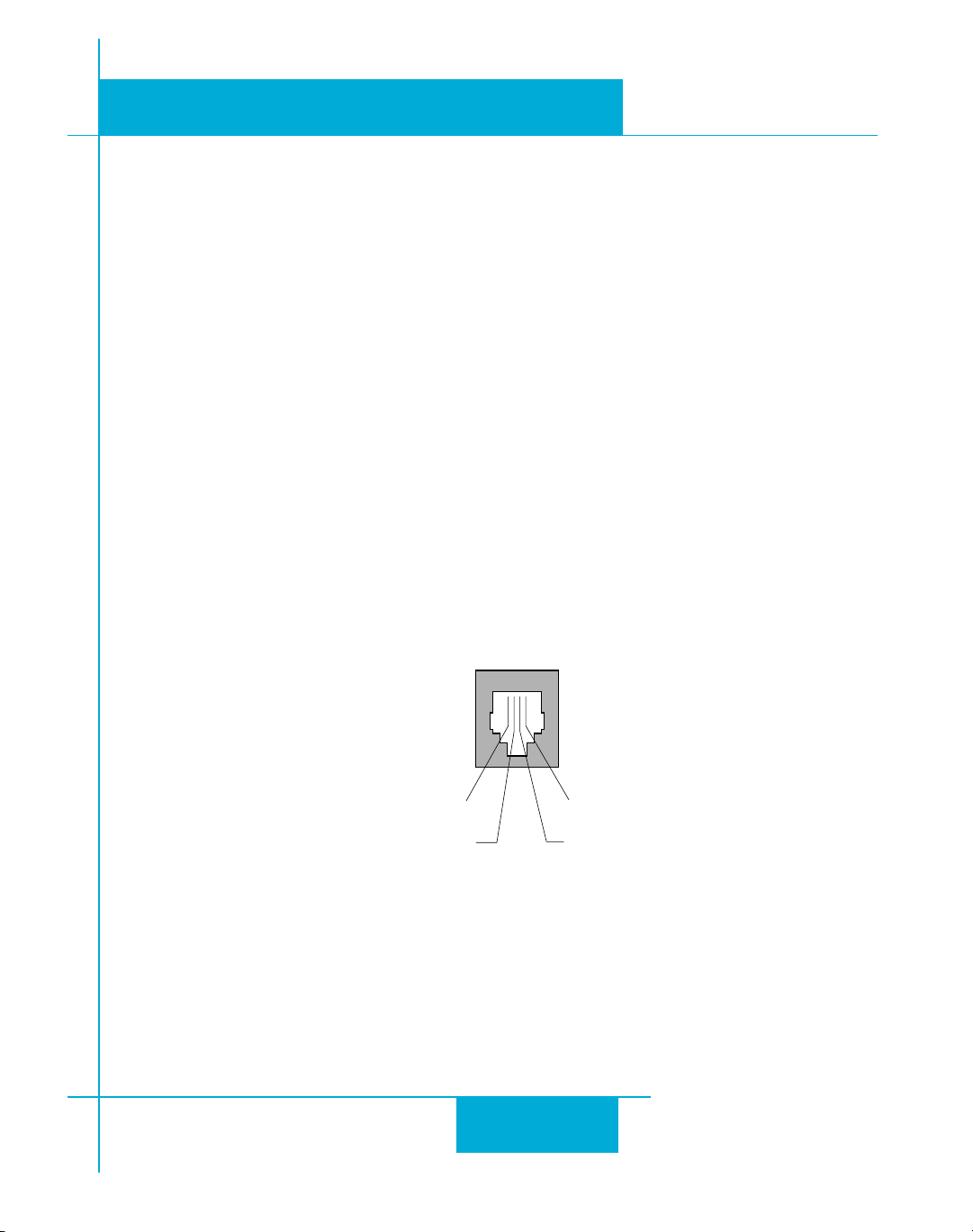
• Your drive was shipped with a communication cable. Plug the large end into the serial port of
your PC and the small end into the PC/MMI jack on your drive. Secure the cable to the PC with
the screws on the sides.
Never connect a drive to a telephone circuit. It uses the same connectors and
cords as telephones and modems, but the voltages are not compatible.
If your PC does not have a serial port, you should purchase a “USB Serial Converter”. We have
had good results with the Port Authority “USB Serial DB9” Adapter from CablesToGo.com and with
the SW1301 from SewellDirect.com.
For laptops, a PCMCIA converter card is a good choice. Our applications engineers use the SSP-
100 from Sewell Direct.
77
7
77
RX (to PC TX)
No connection
ground (to PC ground)
TX (to PC RX)
Pin Assignments of the PC/MMI Port
(RJ11 connector)
Page 8
920-0004 Rev. A4
5/707
ST5/10-Si,-Q Hardware manualST5/10-Si,-Q Hardware manual
ST5/10-Si,-Q Hardware manual
ST5/10-Si,-Q Hardware manualST5/10-Si,-Q Hardware manual
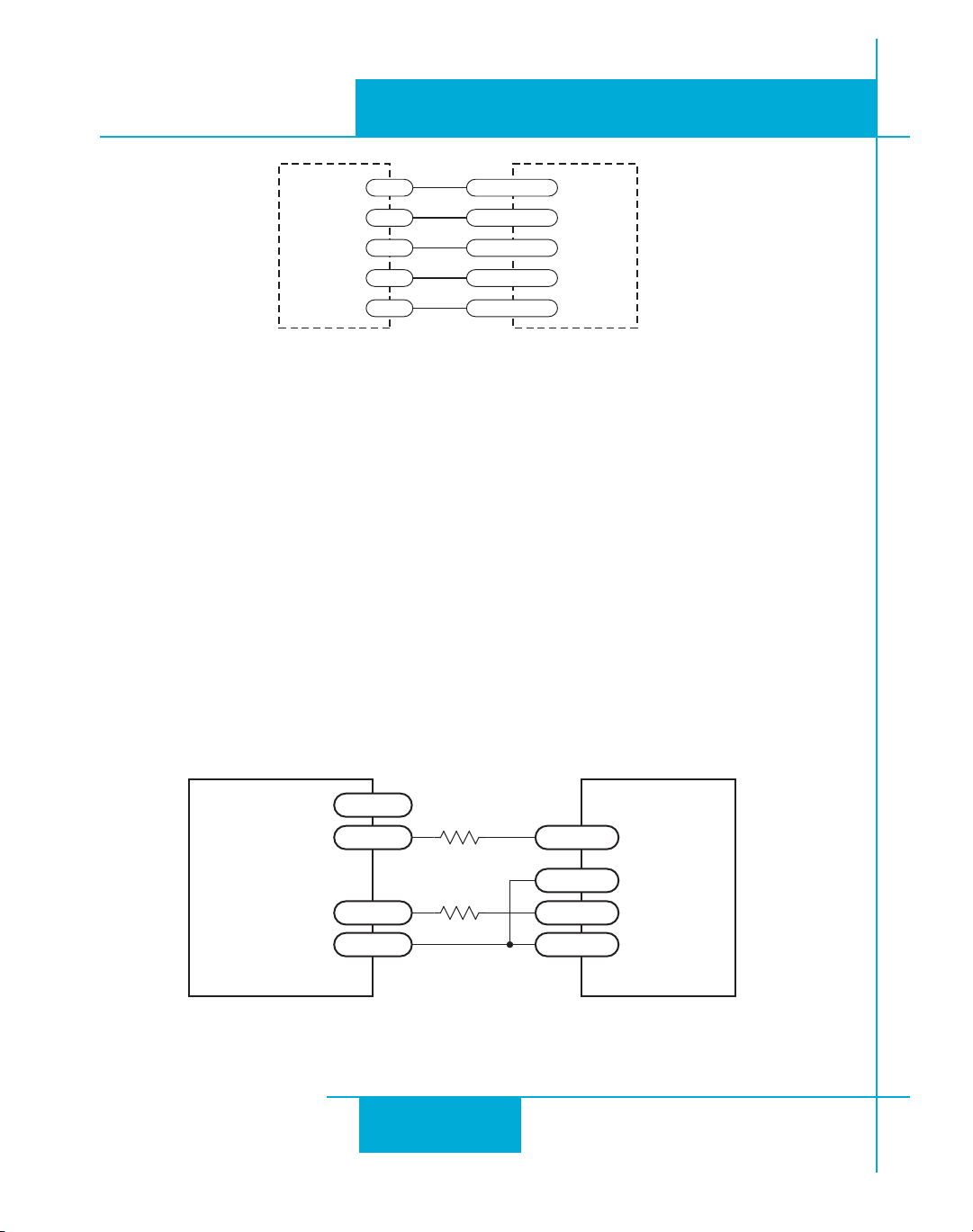
Connecting to a host using RS-485 option card
RS-485 allows you to connect more than one drive to a single host PC, PLC, HMI
or other computer. It also allows the communication cable to be long (more than
1000 feet). But the device to which you connect must have an RS-485 port.
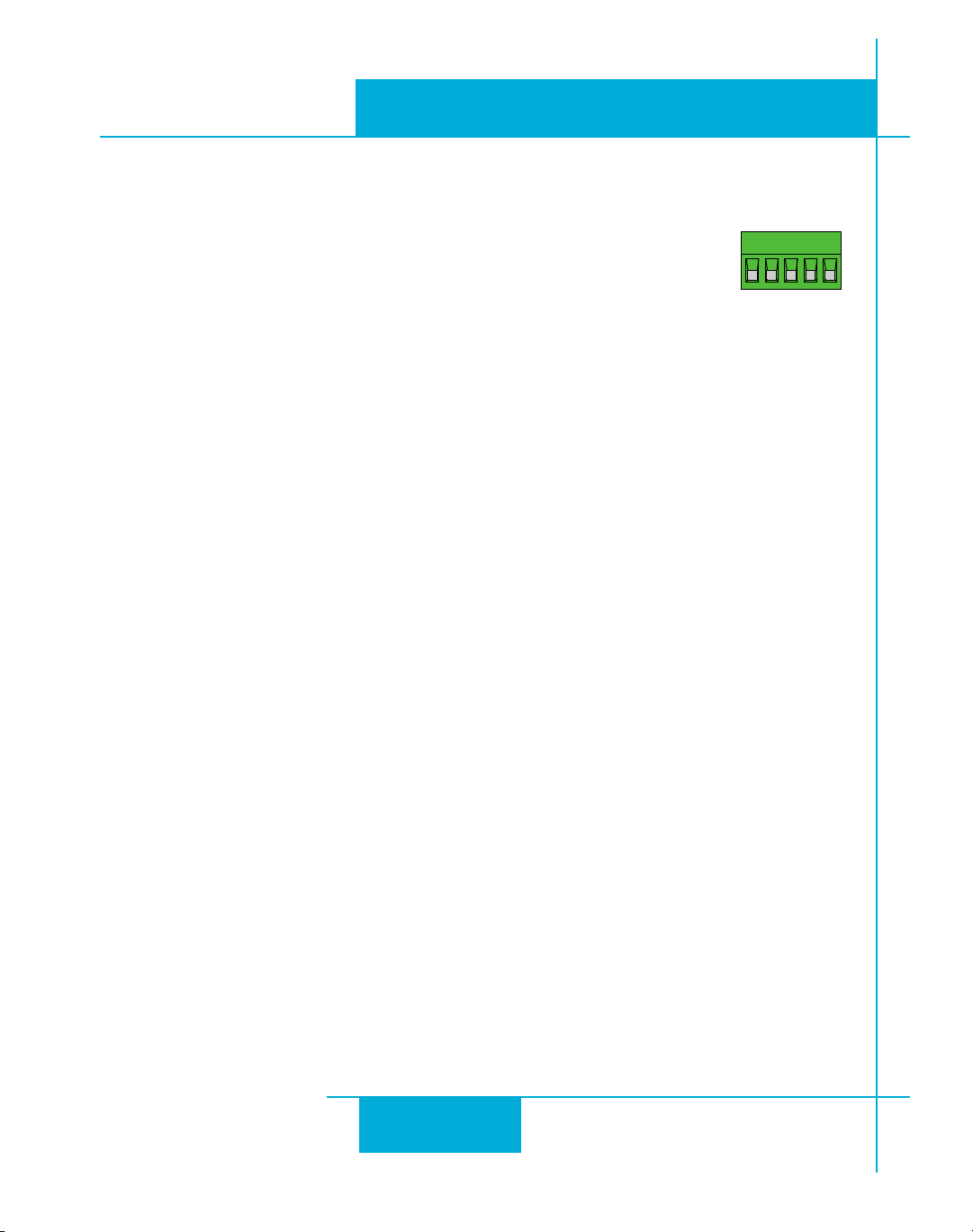
Pin diagram is shown to the right. Wiring diagrams can be found on the next page.
We recommend the use of Category 5 cable. It is widely used for computer networks, it is inexpensive, easy to get and certified for quality and data integrity.
The ST drives can be used with either two wire or four wire RS-485 implementations. The connection can be point to point (i.e. one drive and one host) or a multi-drop network (one host and up to
32 drives).
Four Wire SystemsFour Wire Systems
Four Wire Systems utilize separate transmit and receive wires. One pair of wires must connect
Four Wire SystemsFour Wire Systems
the host computer's transmit signals to each drive's RX+ and RX- terminals. Another pair connects
the TX+ and TX- drive terminals to the host computer's receive signals. A logic ground terminal is
provided on each drive and can be used to keep all drives at the same ground potential. This
terminal connects internally to the DC power supply return (V-), so if all the drives on the RS-485
network are powered from the same supply it is not necessary to connect the logic grounds.
should still connect one drive's GND terminal to the host computer ground.should still connect one drive's GND terminal to the host computer ground.
should still connect one drive's GND terminal to the host computer ground.
should still connect one drive's GND terminal to the host computer ground.should still connect one drive's GND terminal to the host computer ground.
RS-485/422
RX+
RX
TX+
–TX–
YY
ouou
Y
ou
YY
ouou
GND
Four wire systems are better than two wire types because the host can send and receive data at the
same time, increasing system throughput. Furthermore, the host never needs to disable its
transmitter, which simplifies your software.
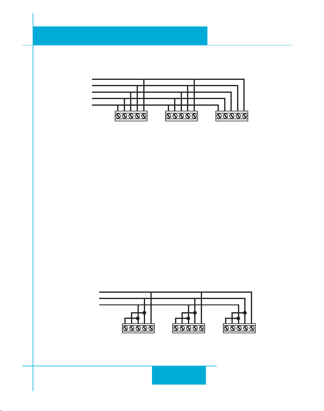
RS-232 to RS-485 4-wire Converter
Model 117701 from Jameco Electronics (800-831-4242) works well for converting your PC’s RS232 port to four wire RS-485. This adaptor is for a 25 pin serial port. If you are like most people
and have a 9 pin serial port on your PC, you will also need to purchase Jameco cable 31721.
Connect as follows:
adaptoradaptor
adaptor
adaptoradaptor
1 RX+
2 RX3 TX4 TX+
drivedrive
drive
drivedrive
88
8
88
Page 9
920-0004 Rev. A4
ST5/10-Si,-Q Hardware manualST5/10-Si,-Q Hardware manual
ST5/10-Si,-Q Hardware manual
ST5/10-Si,-Q Hardware manualST5/10-Si,-Q Hardware manual
5/707
Set the switches for DCE and TxON,RxON. Don't forget to plug in the DC power adaptor that comes
with the unit.
j]ah^
j]nrG
j]nrE
j]lrG
j]lrE
ElrG EnrG ah^ ElrG EnrG ah^ ElrG EnrG ah^
$RIVE $RIVE $RIVE
RS-485 Four Wire System
TT
wo Wire Systemswo Wire Systems
T
wo Wire Systems transmit and receive on the same pair of wires, which can lead to trouble. The
TT
wo Wire Systemswo Wire Systems
host must not only disable its transmitter before it can receive data, it must do so quickly, before a
drive begins to answer a query. The ST drives include a “transmit delay” parameter that can be
adjusted to compensate for a host that is slow to disable its transmitter. This adjustment can be
made over the network using the TD command, or it can be set using the
ST Configurator
software.
It is not necessary to set the transmit delay in a four wire system.
RS-232 to RS-485 2-wire Converter
Model 485-25E from Integrity Instruments (800-450-2001) works well for converting your PC’s
RS-232 port to RS-485. It comes with everything you need.
Connect the adaptor’s “B” pin to the
ST drive’s TX+ and RX+ terminals. Connect “A” to the drive’s TX- and RX- terminals.
Converting USB to RS-485
The USB-COMi-M from www.byterunner.com is an excellent choice for USB to RS-485 conversion.
Set SW1 to ON and SW2-4 to OFF. On the USB-COMi-M screw terminal connector: pin1 goes to
RX- and TX-. Connect pin 2 to RX+ and TX+. Pin 6 is ground. The DB-9 is not used.
j]ah^
j]nrGB[C
j]nrEB\C
ElrG EnrG ah^ ElrG EnrG ah^ ElrG EnrG ah^
$RIVE $RIVE $RIVE
RS-485 Two Wire System
99
9
99
Page 10

920-0004 Rev. A4
5/707
Assigning Addresses
Before wiring the entire system, you'll need to connect each drive individually to the host computer
so that a unique address can be assigned to each drive. Use the programming cable and the
Configurator™
software that came with your drive for this purpose.
ST5/10-Si,-Q Hardware manualST5/10-Si,-Q Hardware manual
ST5/10-Si,-Q Hardware manual
ST5/10-Si,-Q Hardware manualST5/10-Si,-Q Hardware manual
ST
Connect the drive to your PC, then launch the
your drive. If you have already configured your drive, then you should click the Upload button so
that the
select the “SCL” operating mode. If you have a Q drive, you may want to select “Q Programming”.
Either way, you’ll see the RS-485 Address panel appear. Just click on the address character of your
choice. You can use the numerals 0..9 or the special characters ! " # $ % & ' ( ) * + , - . / : ; < = >
? @ . Just make sure that each drive on your network has a unique address. If you are using a 2
wire network, you may need to set the Transmit Delay, too. 10 milliseconds works on the adapters
we’ve tried. Once you’ve made your choices, click Download to save the settings to your drive.
ST Configurator™
settings match those of your drive. Click on the Motion button, then
ST Configurator™
software. Finally, apply power to
1010
10
1010
Page 11
ST5/10-Si,-Q Hardware manualST5/10-Si,-Q Hardware manual
ST5/10-Si,-Q Hardware manual
ST5/10-Si,-Q Hardware manualST5/10-Si,-Q Hardware manual
Connecting the Power Supply
920-0004 Rev. A4
5/707
If you need information about choosing a power supply, please read
located elsewhere in this manual.
Connect the motor power supply "+" terminal to the driver terminal labeled "VDC". Connect power
supply "-" to the drive terminal labeled "GND". Use 18 or 20 gauge wire. The ST drives contain an
internal fuse that connect to the power supply + terminal. This fuse is not user replaceable. If you
want to install a user servicable fuse in your system install a fast acting fuse in line with the +
power supply lead. Use a 4 amp fuse for the ST5 drives and 7 amps for the ST10.
The green ground screw on the corner of the chassis should be connected to earth ground.
Be careful not to reverse the wires. Reverse connection will destroy your driver,
void your warranty and generally wreck your day.
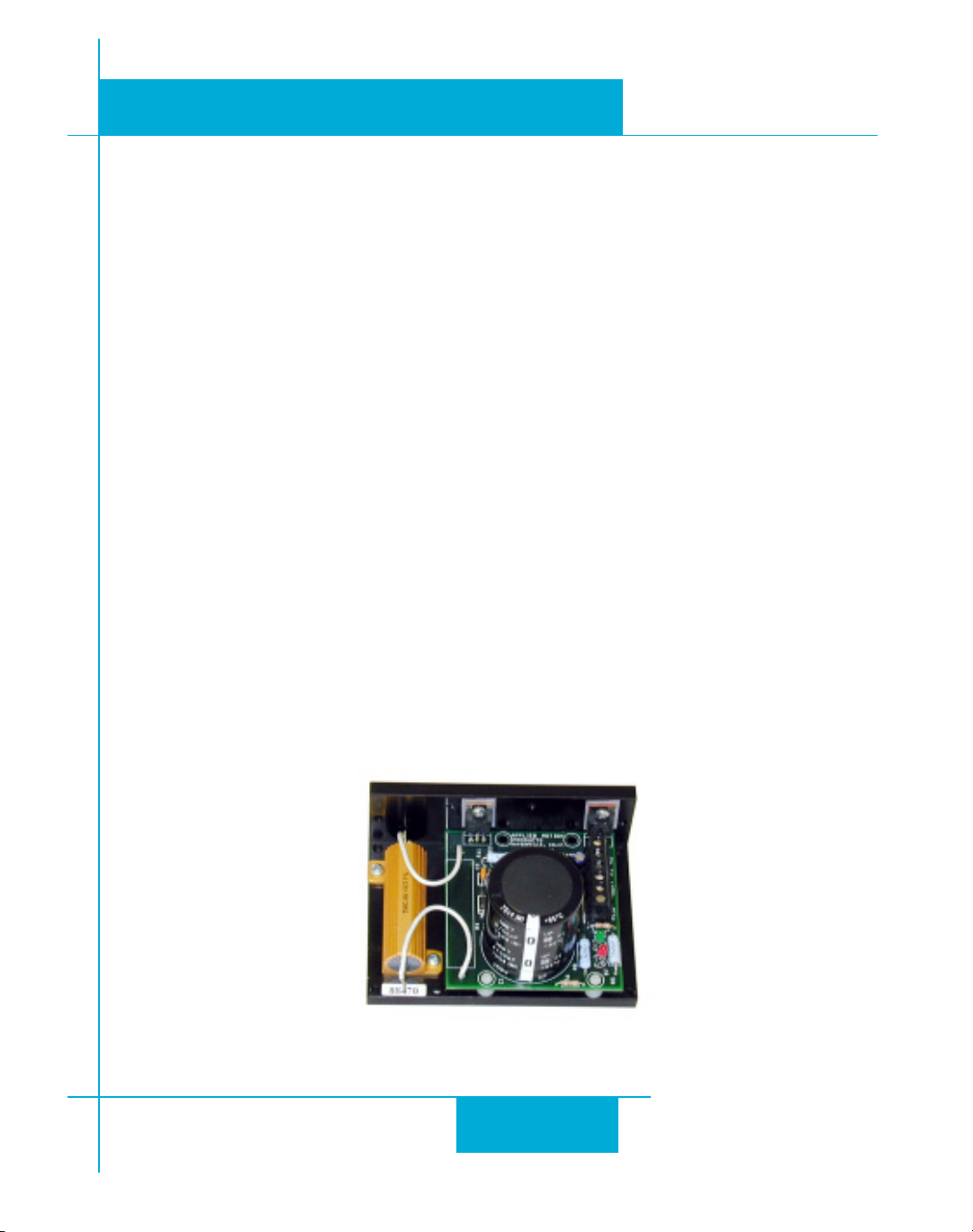
If you plan to use a regulated power supply you may encounter a problem with regeneration. If you
rapidly decelerate a load from a high speed, much of the kinetic energy of that load is transferred
back to the power supply. This can trip the overvoltage protection of a switching power supply,
causing it to shut down. We offer the RC050 “regeneration clamp” to solve this problem. If in
doubt, buy an RC050 for your first installation. If the “regen” LED on the RC050 never flashes, you
don’t need the clamp.
Choosing a Power Supply
RC050 Regen Clamp
1111
11
1111
Page 12
920-0004 Rev. A4
5/707
ST5/10-Si,-Q Hardware manualST5/10-Si,-Q Hardware manual
ST5/10-Si,-Q Hardware manual
ST5/10-Si,-Q Hardware manualST5/10-Si,-Q Hardware manual
Connecting the Motor
Never connect or disconnect the motor while the
power is on.
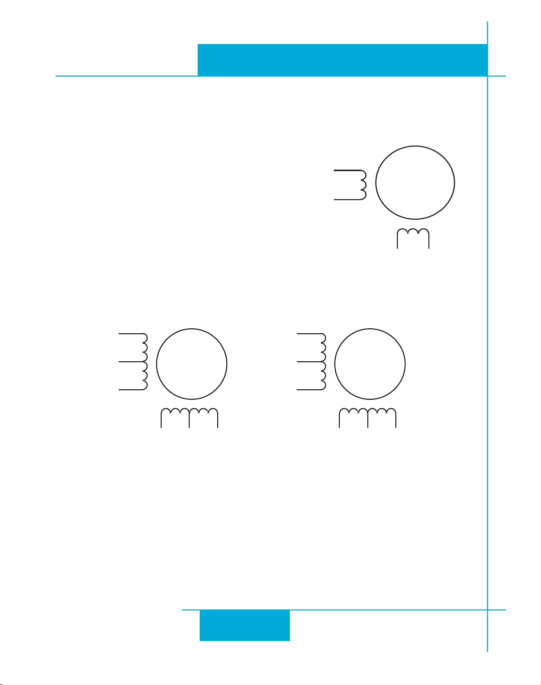
Four lead motorsFour lead motors
Four lead motors can only be connected one way. Please
Four lead motorsFour lead motors
follow the sketch at the right.
Six lead motorsSix lead motors
Six lead motors can be connected in series or center tap.
Six lead motorsSix lead motors
In series mode, motors produce more torque at low speeds,
but cannot run as fast as in the center tap configuration. In
series operation, the motor should be operated at 30% less
than the rated current to prevent overheating. Winding
diagrams for both connection methods are shown below.
NC means not connected.
!n
.#
!
'RN7HT
7HITE
'REEN
2ED
"n
MOTOR
"LACK
LEAD
.#
2ED
7HT
"
!n
!
.#
'RN7HT
7HITE
'REEN
!
!n
2ED
2ED
"LUE
"LACK
9ELLOW
,EADS
LEAD
MOTOR
""n
LEAD
MOTOR
7HITE
" "n
2ED
7HT
.#
,EADS3ERIES#ONNECTED ,EADS#ENTER4AP#ONNECTED
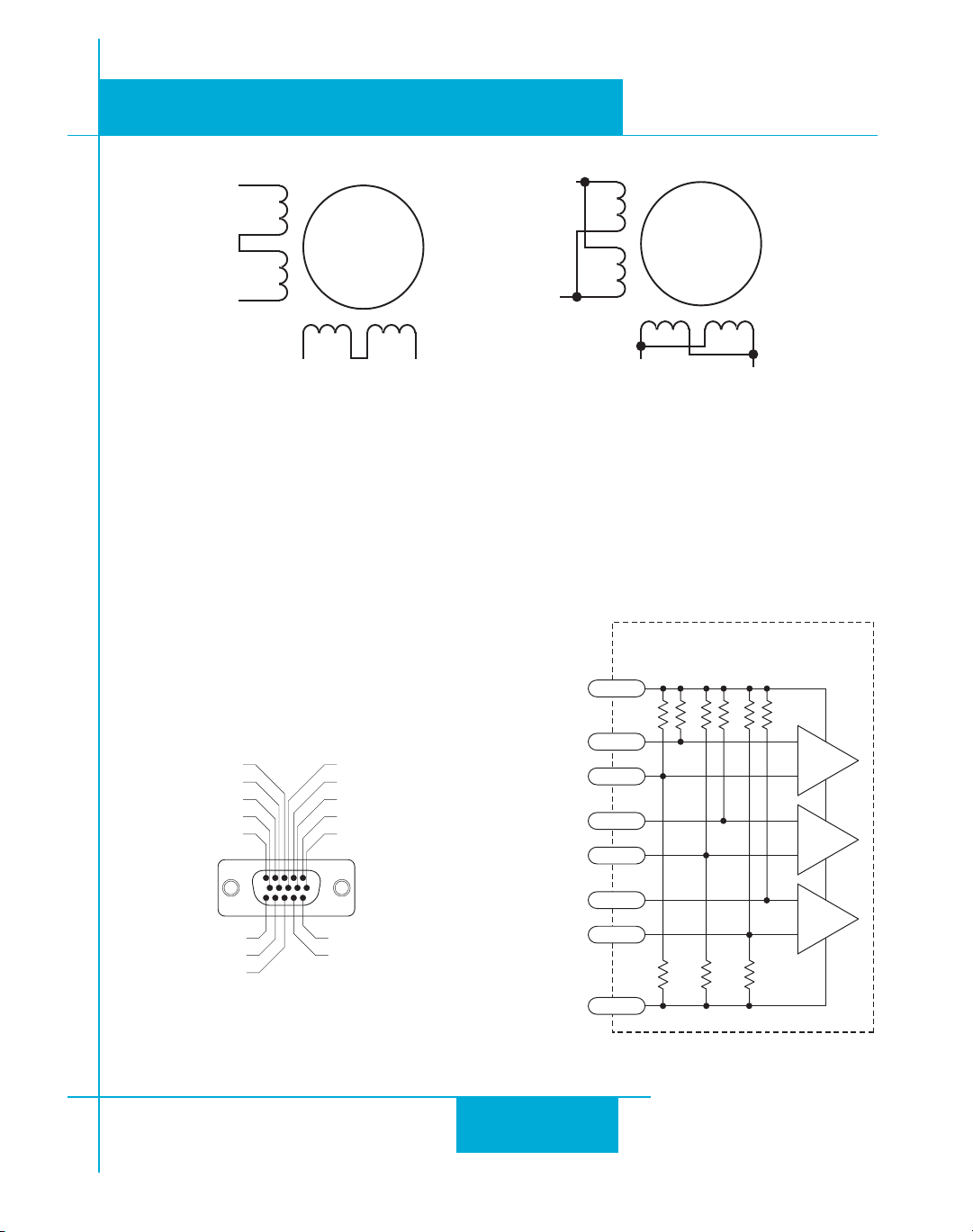
Eight lead motorsEight lead motors
Eight lead motors can also be connected in two ways: series and parallel. As with six lead
Eight lead motorsEight lead motors
motors, series operation gives you less torque at high speeds, but may result in lower motor
losses and less heating. In series operation, the motor should be operated at 30% less than the
unipolar rated current. Thye motors recommended on page 26 should be connected in parallel.
The wiring diagrams for eight lead motors are shown on the next page.
1212
12
1212
Page 13
ST5/10-Si,-Q Hardware manualST5/10-Si,-Q Hardware manual
ST5/10-Si,-Q Hardware manual
ST5/10-Si,-Q Hardware manualST5/10-Si,-Q Hardware manual
920-0004 Rev. A4
5/707
/RANGE
!
/RG7HT
"LK7HT
LEAD
"LK7HT
!n
"LACK
2ED
,EADS3ERIES#ONNECTED ,EADS0ARALLEL#ONNECTED
MOTOR
2ED
9EL
7HT
" "n
7HT
!n
9ELLOW
!
/RG
7HT
/RANGE
"LACK
2ED
"
9EL
7HT
LEAD
MOTOR
2ED7HT
9EL
LOW
"n
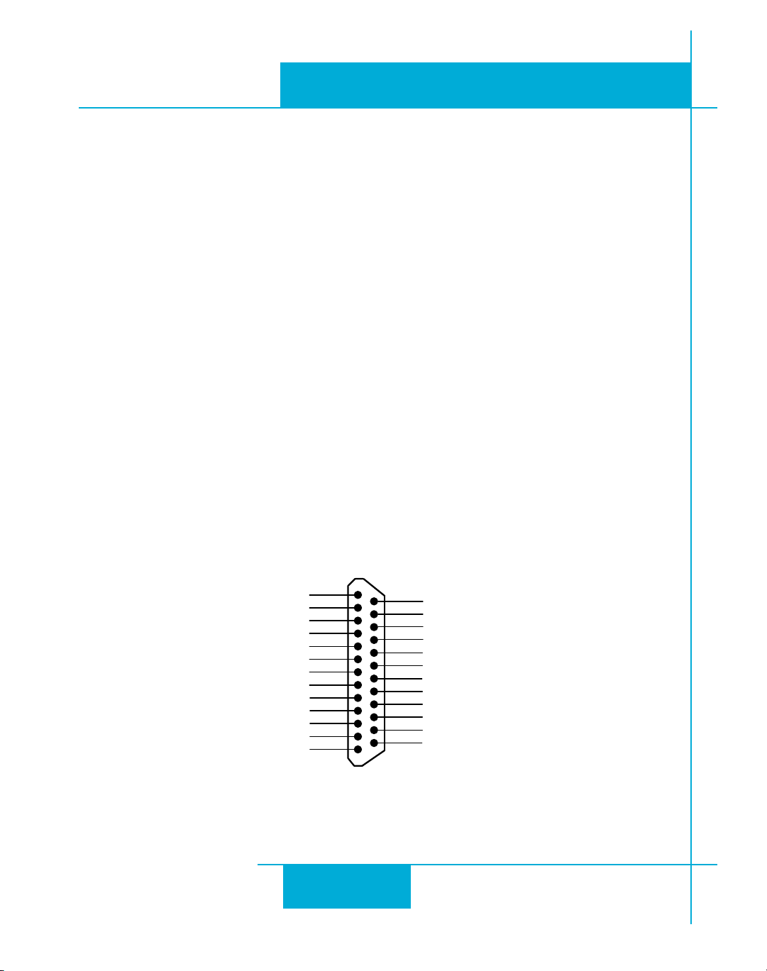
Connecting an Encoder (Requires the optional Encoder Feedback Card)
The encoder connections use a HD-15 connector, which you must connect to your encoder as
shown below. See back page for mating connector information.
If your encoder is single ended, connect the encoder
outputs to the A+, B+ and Z+ inputs. Leave A-, B- and
Z- unconnected. (Z is the encoder index signal and is
optional.)
ENCODER"
DONOTCONNECT
ENCODER"
DONOTCONNECT
ENCODER:
SHIELD
DONOTCONNECT
DONOTCONNECT
`p
'.$
ENCODER!
6$#M!
ENCODER!
ENCODER:
DONOTCONNECT
DONOTCONNECT
6
!
!
"
"
($#ONNECTOR
:
:
'.$
INSIDEDRIVE
+
+
+
+
+
+
+
+
+
Pin Assignments (facing drive)
1313
13
1313
Internal Circuit
Page 14
920-0004 Rev. A4
5/707
ST5/10-Si,-Q Hardware manualST5/10-Si,-Q Hardware manual
ST5/10-Si,-Q Hardware manual
ST5/10-Si,-Q Hardware manualST5/10-Si,-Q Hardware manual
Connecting Input Signals
The ST drives have three types of inputs:
• high speed digital inputs for step & direction commands or encoder following, 5 volt logic
• digital inputs for other signals, 12 - 24 volt logic
• analog inputs for analog speed and positioning modes
All drives include eight digital inputs and two analog inputs.
• CW & CCW Limit: can be used to inhibit motion in a given direction, forcing the motor and load
to travel within mechanical limits. Can be configured for active closed, active open or not used.
• IN1/STEP & IN2/DIR: digital signals for commanding position. Quadrature signals from encoders can also be used. These inputs can also be connected to sensors, switches and other devices
for use with Q and Si™ commands such as
others.
• IN3,4,5,6: software programmable inputs can be used for motor enable, alarm reset or jogging.
These inputs can also be connected to sensors, switches and other devices for use with Q and Si™
Wait Input, Seek Home, Feed to Sensor, If Input
• Analog In: analog velocity or position command signal. Can be configured for 0-10V, 0-5V,
±10V or ±5V, with or without offset.
Wait Input, Seek Home, Feed to Sensor, If Input
and other commands.
and
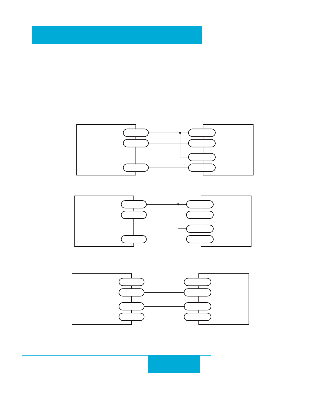
Connector Pin Diagram
nJEWwh{{
Ww}_dG
Ww}_dH
nLEYYm`e]
nKEYm`e]
nIE[wx{
nYecced
nHEZ_hC
nHEZ_hA
nGEij[fC
nGEij[fA
]dZ
IN/OUT1 (DB-25) Connector
)./54
1
2
3
4
5
6
7
8
9
10
11
12
13
&RONT6IEW
1414
14
1414
14
15
16
17
18
19
20
21
22
23
24
25
oGEXhWa[
oHEcej_ed
oIE\Wkbj
oYecced
AKlekj
]dZ
oJA
oJC
nMEYmb_c_jA
nMEYmb_c_jC
nNEYYmb_c_jA
nNEYYmb_c_jC
Page 15
920-0004 Rev. A4
ST5/10-Si,-Q Hardware manualST5/10-Si,-Q Hardware manual
ST5/10-Si,-Q Hardware manual
ST5/10-Si,-Q Hardware manualST5/10-Si,-Q Hardware manual
High Speed Digital Inputs
The ST-Q and ST-Si drives include two high speed inputs called STEP and DIR. They accept 5 volt
single-ended or differential signals, up to 2 MHz. Normally these inputs connect to an external
controller that provides step & direction command signals. You can also connect a master encoder
to the high speed inputs for following applications. Or you can use these inputs with
Input, Feed to Sensor, Seek Home
Connection diagrams follow.
and other such commands.
Wait Input, If
5/707
)NDEXER
WITH
3OURCING
/UTPUTS
Connecting to indexer with Sourcing Outputs
)NDEXER
WITH
3INKING
/UTPUTS
Connecting to Indexer with Sinking Outputs
)NDEXER
WITH
$IFFERENTIAL
/UTPUTS
#/-
$)2 8$)2
34%0 834%0
6/54
$)2 8$)2
34%0 834%0
$)2
$)2 8$)2
34%0
34%0
8$)2
834%0
8$)2
834%0
8$)2
834%0
834%0
)./54
)./54
)./54
Connecting to Indexer with Differential Outputs
(Many High Speed Indexers have Differential Outputs)
1515
15
1515
Page 16
920-0004 Rev. A4
5/707
ST5/10-Si,-Q Hardware manualST5/10-Si,-Q Hardware manual
ST5/10-Si,-Q Hardware manual
ST5/10-Si,-Q Hardware manualST5/10-Si,-Q Hardware manual
834%0
834%0
8$)2
8$)2
'.$
DRIVE
3IOR1
-ASTER
%NCODER
!
!
"
"
'.$
Wiring for Encoder Following
Using High Speed Inputs with 12-24 Volt Signals
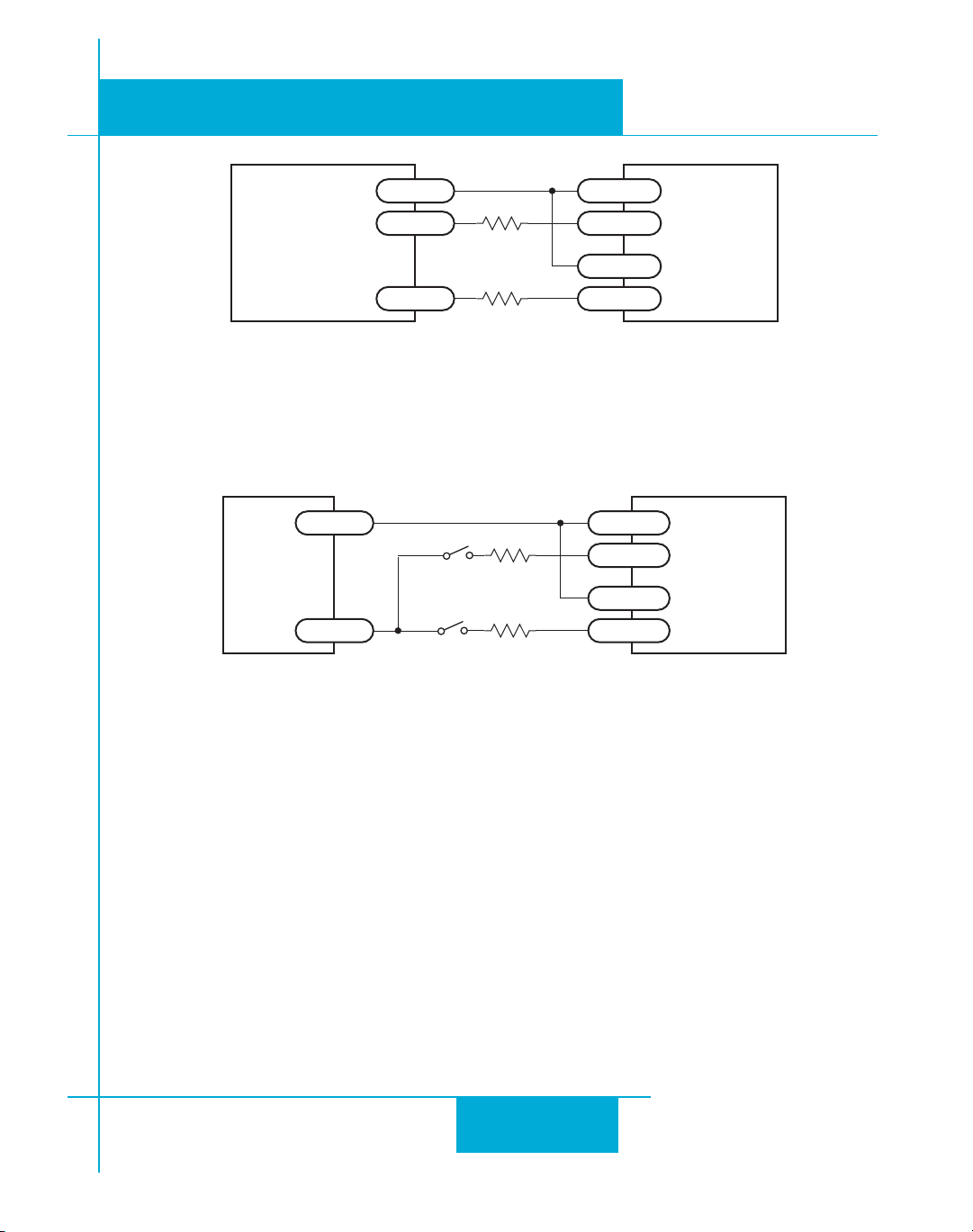
Most PLCs don't use 5 volt logic. You can connect signal levels as high as 24 volts to the STEP
and DIR inputs if you add external dropping resistors, as shown below.
• For 12 volt logic, add 820 ohm, 1/4 watt resistors
• For 24 volt logic, use 2200 ohm, 1/4 watt resistors
The maximum voltage that can be applied to an input terminal is 24 volts DC.
Never apply AC voltage to an input terminal.
0,#
6
WITH
3OURCING
/UTPUTS
/54 8$)2
2
2
/54 834%0
'.$
834%0
8$)2
Connecting to PLC with Sourcing (PNP) Outputs
(Most PLC's use 24 volt logic)
1616
16
1616
3IOR1
$RIVE
Page 17
ST5/10-Si,-Q Hardware manualST5/10-Si,-Q Hardware manual
ST5/10-Si,-Q Hardware manual
ST5/10-Si,-Q Hardware manualST5/10-Si,-Q Hardware manual
920-0004 Rev. A4
5/707
0,#
WITH
3INKING
/UTPUTS
6$#
0OWER
3UPPLY
6
$)2 8$)2
2
2
34%0 834%0
8$)2
3IOR1
$RIVE
834%0
Connecting to PLC with Sinking (NPN) Outputs
(Most PLC's use 24 volt logic)
834%0
DIRECTIONSWITCH
RUNSTOPSWITCH
CLOSEDRUN
8$)2
8$)2
834%0
3IOR1
$RIVE
Using Mechanical Switches at 24 Volts
1717
17
1717
Page 18
920-0004 Rev. A4
5/707
ST5/10-Si,-Q Hardware manualST5/10-Si,-Q Hardware manual
ST5/10-Si,-Q Hardware manual
ST5/10-Si,-Q Hardware manualST5/10-Si,-Q Hardware manual
Other Digital Inputs
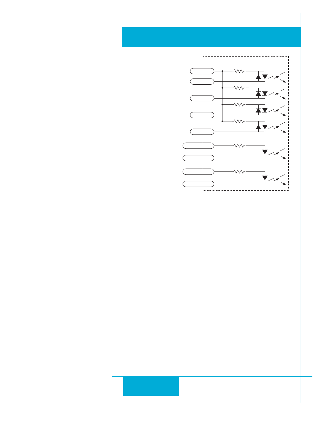
As we mentioned in the previous section, the high
8#/-
8%.
INSIDEDRIVE
speed STEP and DIR inputs are configured for five
volt logic. All other digital inputs are designed for
operation between 12 and 24 volts DC.
Single Ended Inputs
The ST drives include four single ended, optically
isolated input circuits that can be used with
sourcing or sinking signals, 12 to 24 volts. This
allows connection to PLCs, sensors, relays and
mechanical switches. Because the input circuits
are isolated, they require a source of power. If you
are connecting to a PLC, you should be able to get
8234
8
8
8#7,)-
$"#ONNECTOR
8#7,)-
8##7,)-
8##7,)-
power from the PLC power supply. If you are
using relays or mechanical switches, you will need a 12-24 V power supply. This also applies if
you are connecting the inputs to the programmable outputs of an Si product from Applied Motion.
What is COM?
"Common" is an electronics term for an electrical connection to a common voltage. Sometimes
"common" means the same thing as "ground", but not always. In the case of the ST drives, if you
are using sourcing (PNP) input signals, then you will want to connect COM to ground (power
supply -). If you are using sinking (NPN) signals, then COM must connect to power supply +.
Note: If current is flowing into or out of an input, the logic state of that input is low or closed. If no
current is flowing, or the input is not connected, the logic state is high or open.
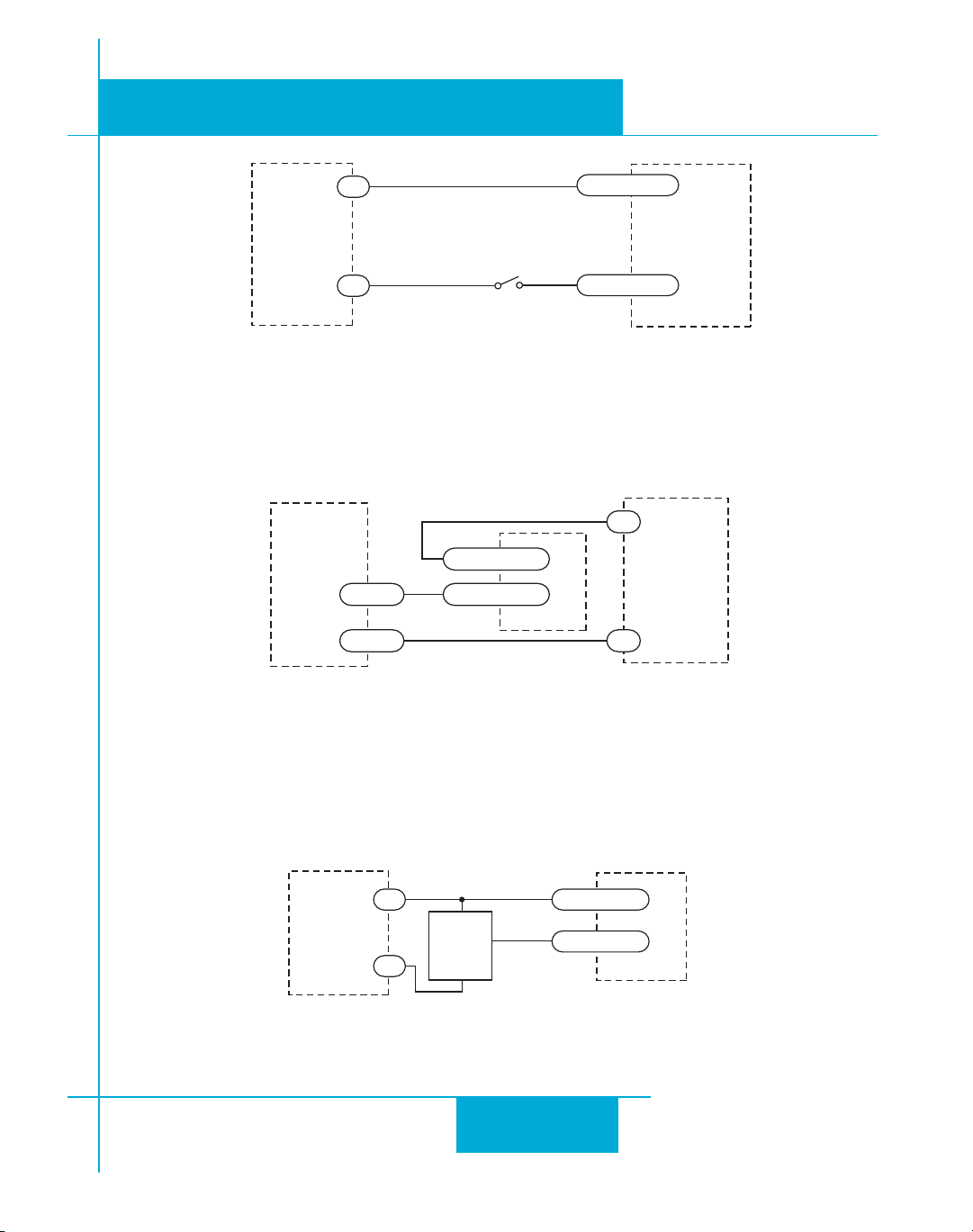
The diagrams on the following pages show how to connect the inputs to various commonly used
devices.
1818
18
1818
Page 19
ST5/10-Si,-Q Hardware manualST5/10-Si,-Q Hardware manual
ST5/10-Si,-Q Hardware manual
ST5/10-Si,-Q Hardware manualST5/10-Si,-Q Hardware manual
920-0004 Rev. A4
5/707
6$#
0OWER
3UPPLY
3IDRIVE
SWITCHORRELAY
CLOSEDLOGICLOW
Connecting an Input to a Switch or RelayConnecting an Input to a Switch or Relay
Connecting an Input to a Switch or Relay
Connecting an Input to a Switch or RelayConnecting an Input to a Switch or Relay
8#/-
88
)./54
8#/-
/54
88
/54n
Connecting another Si™ drive to the ST
(When output closes, input goes low).
)./54
6$#
0OWER
3UPPLY
6$#
0OWER
3UPPLY
Connecting an NPN Type Proximity Sensor to an input
(When prox sensor activates, input goes low).
.0.
0ROXIMITY
3ENSOR
n
OUTPUT
1919
19
1919
8#/-
88
)./54
Page 20
920-0004 Rev. A4
5/707
ST5/10-Si,-Q Hardware manualST5/10-Si,-Q Hardware manual
ST5/10-Si,-Q Hardware manual
ST5/10-Si,-Q Hardware manualST5/10-Si,-Q Hardware manual
6$#
0OWER
3UPPLY
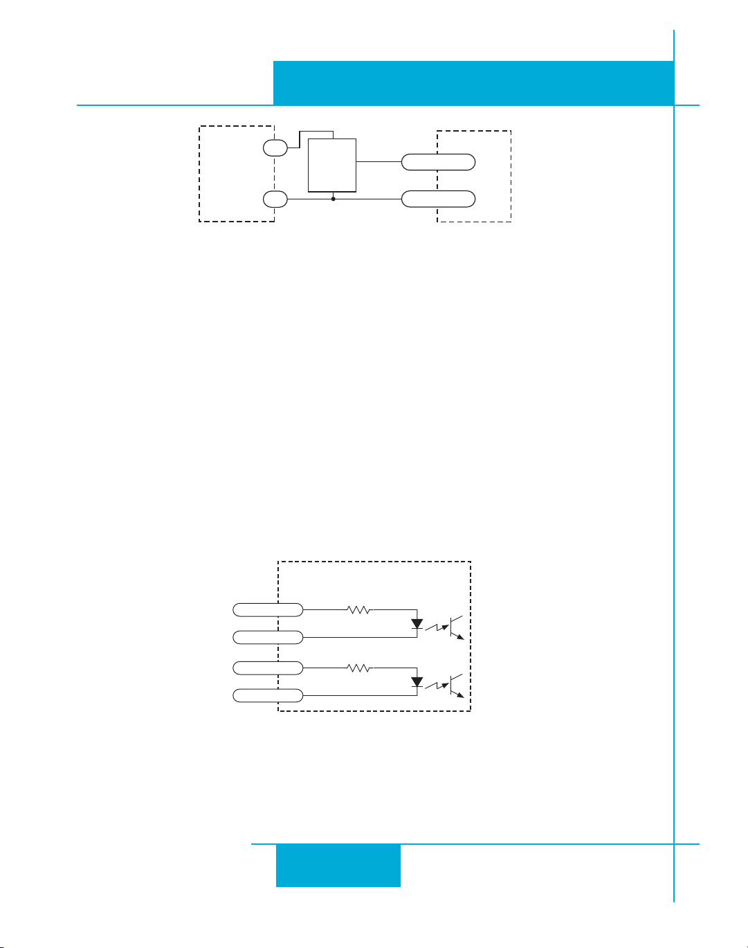
Connecting a PNP Type Proximity Sensor to a an input
(When prox sensor activates, input goes low).
0.0
0ROXIMITY
3ENSOR
n
OUTPUT
88
)./54
8#/-
Connecting Limit Switches
The CWLIMIT and CCWLIMIT inputs are used for connecting end of travel sensors. These inputs
are differential, which allows you to use signals that are sinking (NPN), sourcing (PNP) or differential (line driver). By connecting switches or sensors that are triggered by the motion of the motor
or load, you can force the motor to operate within certain limits. This is useful if a program or
operator error could cause damage to your system by traveling too far.
The limit inputs are optically isolated. This allows you to choose a voltage for your limit circuits of
12 to 24 volts DC. This also allows you to have long wires on limit sensors that may be far from
the drive with less risk of introducing noise to the drive electronics. The schematic diagram of the
limit switch input circuit is shown below.
8#7,)-
8#7,)-
8##7,)-
8##7,)-
INSIDEDRIVE
)./54#ONNECTOR
2020
20
2020
Page 21
920-0004 Rev. A4
ST5/10-Si,-Q Hardware manualST5/10-Si,-Q Hardware manual
ST5/10-Si,-Q Hardware manual
ST5/10-Si,-Q Hardware manualST5/10-Si,-Q Hardware manual
5/707
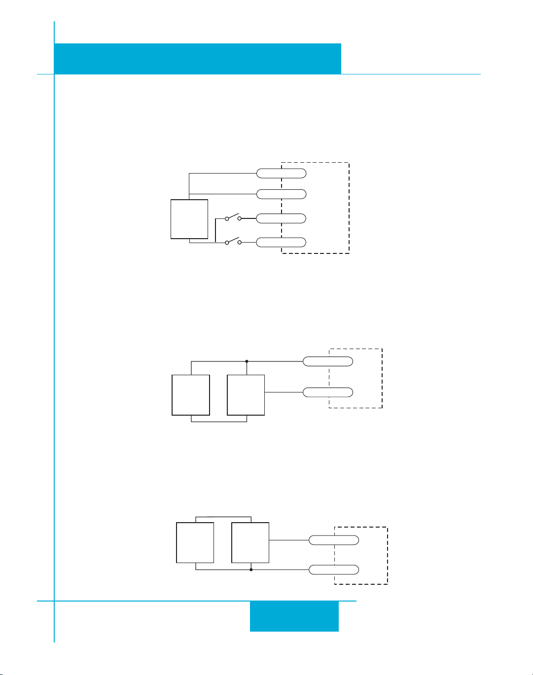
Wiring a Mechanical Limit Switch
You can use normally open or normally closed limit switches. Either way, wire them as shown
here. Be sure to set the polarity using the
Si Programmer™
for Si™ drives or the
ST Configurator™
software for the ST5-Q and ST10-Q.
#7,)-)4
)./54
6$#
3500,9
##7,)-)4
#7,)-)4
##7,)-)4
Wiring a Limit Sensor
Some systems use active limit sensors that produce a voltage output rather than a switch or relay
closure. These devices must be wired differently than switches.
If your sensor has an open collector output or a sinking output, wire it like this:
#7,)-)4
E
^]
j
m
¨
E
f
m
¨
chIionK
#7,)-)4
If the sensor output goes low at the limit, select the option “closed” (in the software). If the output
is open, or high voltage, choose “open”.
Other sensors have sourcing outputs. That means that current can flow out of the sensor output,
but not into it. In that case, wire the sensor this way:
E
^]
j
m
¨
E
j
m
¨
2121
21
2121
#7,)-)4
chIionK
#7,)-)4
Page 22
920-0004 Rev. A4
5/707
ST5/10-Si,-Q Hardware manualST5/10-Si,-Q Hardware manual
ST5/10-Si,-Q Hardware manual
ST5/10-Si,-Q Hardware manualST5/10-Si,-Q Hardware manual
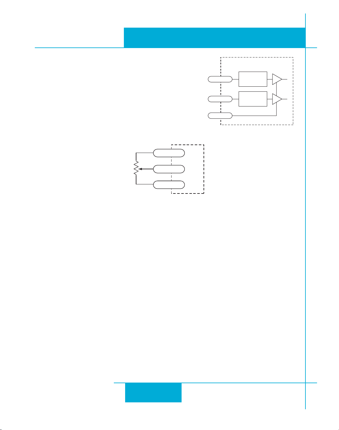
Analog Inputs
The ST drives feature two analog inputs. Each input can
accept a signal range of 0 to 5 VDC, ±5 VDC, 0 to 10 VDC
or ±10 VDC. The drive can be configured to operate at a
speed or position that is proportional to the analog signal.
Use the
offset, deadband and filter frequency.
ST Configurator
Connecting a Potentiometer to Analog Input 1
software to set the signal range,
6/54
K7
POT
CW
CCW
!).
'.$
!).
!).
'.$
$"#ONNECTOR
_dEekjG
INSIDEDRIVE
3IGNAL
#ONDITIONING
3IGNAL
#ONDITIONING
2222
22
2222
Page 23
ST5/10-Si,-Q Hardware manualST5/10-Si,-Q Hardware manual
ST5/10-Si,-Q Hardware manual
ST5/10-Si,-Q Hardware manualST5/10-Si,-Q Hardware manual
920-0004 Rev. A4
5/707
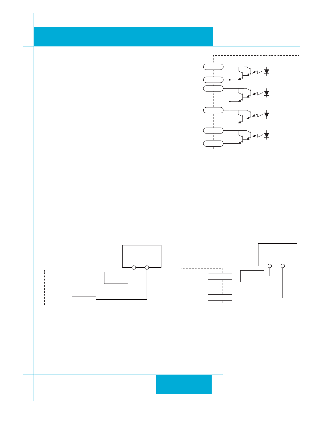
Programmable Outputs
The ST drives feature four digital outputs. These outputs
can be set to automically control a motor brake, to signal a
fault condition, to indicate when the motor is moving or to
provide an output frequency proportional to motor speed
(tach signal). Or the outputs can be turned on and off by
program instructions like Set Output.
The outputs can be used to drive LEDs, relays and the
inputs of other electronic devices like PLCs and counters.
9
9#/-
9
9
9
9
)./54
For OUT4, the “+” (collector) and “-” (emitter) terminals of
each transistor are available at the connector. This allows
you to configure each output for current sourcing or sinking. The OUT1-3 outputs can only sink
current. The COM terminal must be tied to power supply (-).
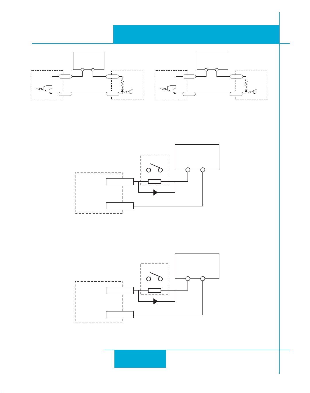
Diagrams of each type of connection follow.
Do not connect the outputs to more than 30VDC.
The current through each output terminal must not exceed 100 mA.
)./54
9
9#/-
,OAD
6$#
0OWER3UPPLY
n
)./54
2323
23
2323
9
9
,OAD
Sinking Output
Using Y4
6$#
0OWER3UPPLY
n
Page 24
920-0004 Rev. A4
5/707
ST5/10-Si,-Q Hardware manualST5/10-Si,-Q Hardware manual
ST5/10-Si,-Q Hardware manual
ST5/10-Si,-Q Hardware manualST5/10-Si,-Q Hardware manual
)./54
6$#
0OWER3UPPLY
n
9
9#/-
Sourcing Output
Y1, Y2 or Y3
)./54
#/-
).
9
9#/-
)./54
0,#
RELAY
.SUPPRESSIONDIODE
Driving a Relay
Y1, Y2 or Y3
6$#
0OWER3UPPLY
n
9
9
Sourcing Output
Using Y4
6$#
0OWER3UPPLY
n
#/-
).
0,#
)./54
9
.SUPPRESSIONDIODE
9
Driving a Relay
Using Y4
2424
24
2424
RELAY
6$#
0OWER3UPPLY
n
Page 25

920-0004 Rev. A4
ST5/10-Si,-Q Hardware manualST5/10-Si,-Q Hardware manual
ST5/10-Si,-Q Hardware manual
ST5/10-Si,-Q Hardware manualST5/10-Si,-Q Hardware manual
5/707
Choosing a Power Supply
When choosing a power supply, there are many things to consider. If you are manufacturing
equipment that will be sold to others, you probably want a supply with all the safety agency
approvals. If size and weight are an issue use a switching supply.
You must also decide what size of power supply (in terms of voltage and current) is needed for
your application.
Voltage
PWM drives work by switching the voltage to the motor terminals on and off while monitoring
current to achieve a precise level of phase current. To do this efficiently and silently, you’ll want to
have a power supply with a voltage rating at least five times that of the motor. Depending on how
fast you want to run the motor, you may need even more voltage than that.
If you choose an unregulated power supplyIf you choose an unregulated power supply
If you choose an unregulated power supply
If you choose an unregulated power supplyIf you choose an unregulated power supply
does not exceed the drive’does not exceed the drive’
does not exceed the drive’
does not exceed the drive’does not exceed the drive’
Current
The maximum supply current you could ever need is the sum of the two phase currents. However,
you will generally need a lot less than that, depending on the motor type, voltage, speed and load
conditions. That's because the ST drives use switching amplifiers, converting a high voltage and
low current into lower voltage and higher current. The more the power supply voltage exceeds the
motor voltage, the less current you’ll need from the power supply. A motor running from a 48 volt
supply can be expected to draw only half the supply current that it would with a 24 volt supply.
We recommend the following selection procedure:
1. If you plan to use only a few drives, get a power supply with at least twice the rated phase
current of the motor.
2. If you are designing for mass production and must minimize cost, get one power supply
with more than twice the rated current of the motor. Install the motor in the application and
monitor the current coming out of the power supply and into the drive at various motor loads.
This will tell you how much current you really need so you can design in a lower cost power
supply.
s maximum input voltage specification.s maximum input voltage specification.
s maximum input voltage specification.
s maximum input voltage specification.s maximum input voltage specification.
, make sure the no load voltage of the supply, make sure the no load voltage of the supply
, make sure the no load voltage of the supply
, make sure the no load voltage of the supply, make sure the no load voltage of the supply
2525
25
2525
Page 26
920-0004 Rev. A4
5/707
Recommended Motors
ST5/10-Si,-Q Hardware manualST5/10-Si,-Q Hardware manual
ST5/10-Si,-Q Hardware manual
ST5/10-Si,-Q Hardware manualST5/10-Si,-Q Hardware manual
PartPart
Part
PartPart
NumberNumber
Number
NumberNumber
HoldingHolding
Holding
HoldingHolding
oz-inoz-in
oz-in
oz-inoz-in
TT
orqueorque
T
orque
TT
orqueorque
kg-cmkg-cm
kg-cm
kg-cmkg-cm
DriveDrive
Drive
DriveDrive
Current SettingCurrent Setting
Current Setting
Current SettingCurrent Setting
ampsamps
amps
ampsamps
ResistanceResistance
Resistance
ResistanceResistance
ohmsohms
ohms
ohmsohms
InductanceInductance
Inductance
InductanceInductance
mHmH
mH
mHmH
RotorRotor
Rotor
RotorRotor
InertiaInertia
Inertia
InertiaInertia
g-cmg-cm
g-cm
g-cmg-cm
22
2
22
HT11-012 7.0 0.50 1.2 1.4 1.4 8
HT11-013 15.0 1.08 1.2 2.0 2.6 18
5014-842 26.0 1.87 1.2 4.3 5.5 20
HT17-068 31.4 2.26 1.6 2.1 2.8 35
HT17-071 51.0 3.67 2.0 1.7 3.6 54
HT17-075 62.8 4.52 2.0 1.7 3.0 68
HT23-395 76.6 5.52 5.0 0.3 0.6 120
HT23-398 177 12.7 5.0 0.4 1.2 300
HT23-401 264 19.0 5.0 0.5 1.6 480
HT34-485 650 46.8 10.0 0.19 1.3 1400
HT34-486 1200 86.4 9.7 0.27 2.2 2680
HT34-487 1845 133 10.0 0.27 2.4 4000
Note: The “Drive Current Setting” shown here differs from the rated current of each motor because
the rated current is RMS and the drive current setting is peak sine. If you are using a motor not
listed here, for best results set the drive current at the motor’s rated current x 1.2.
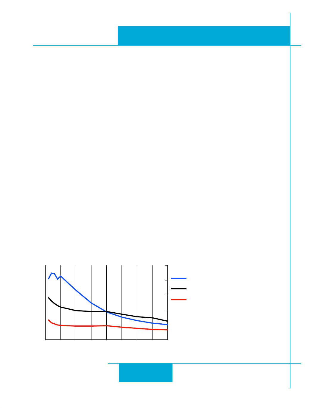
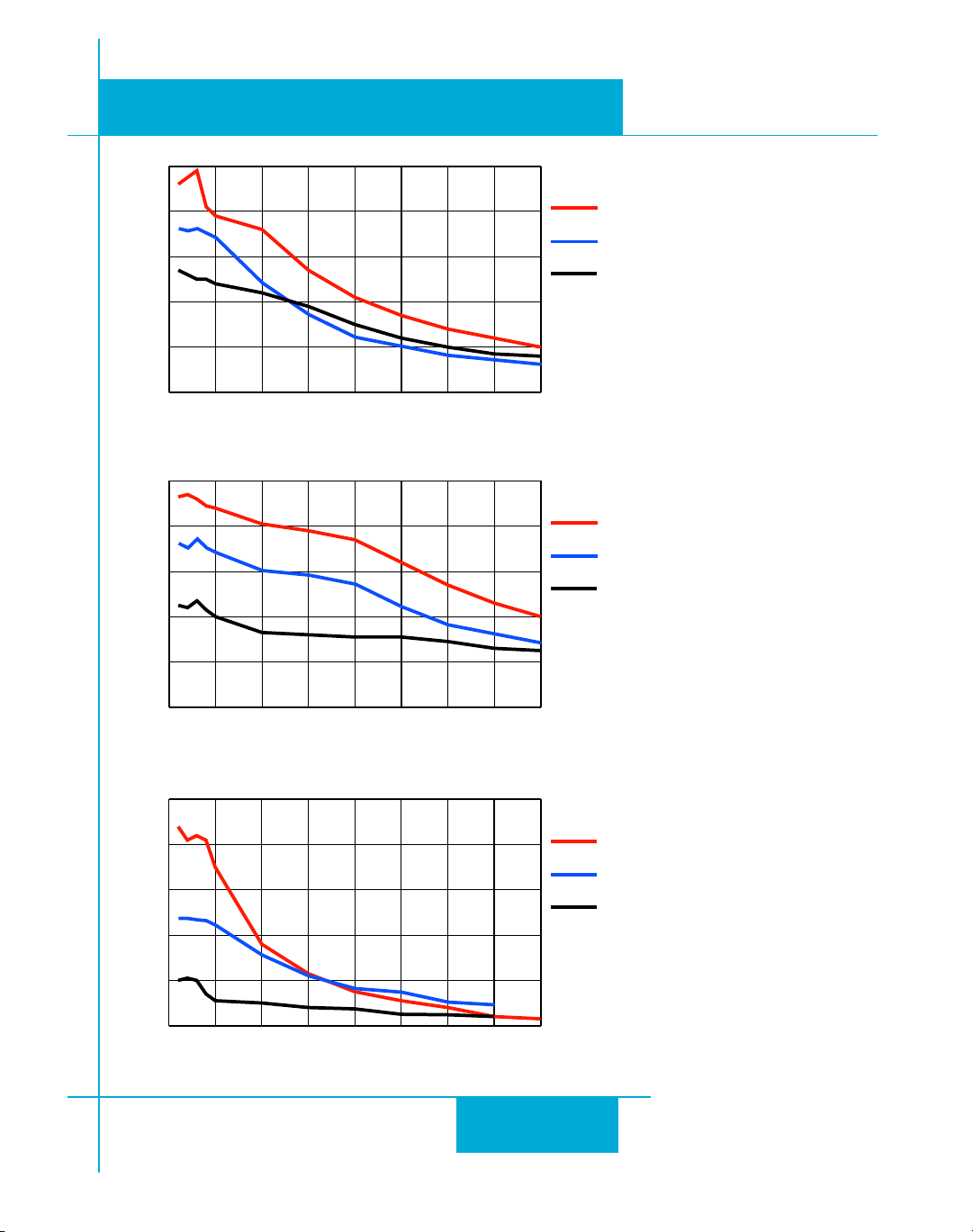
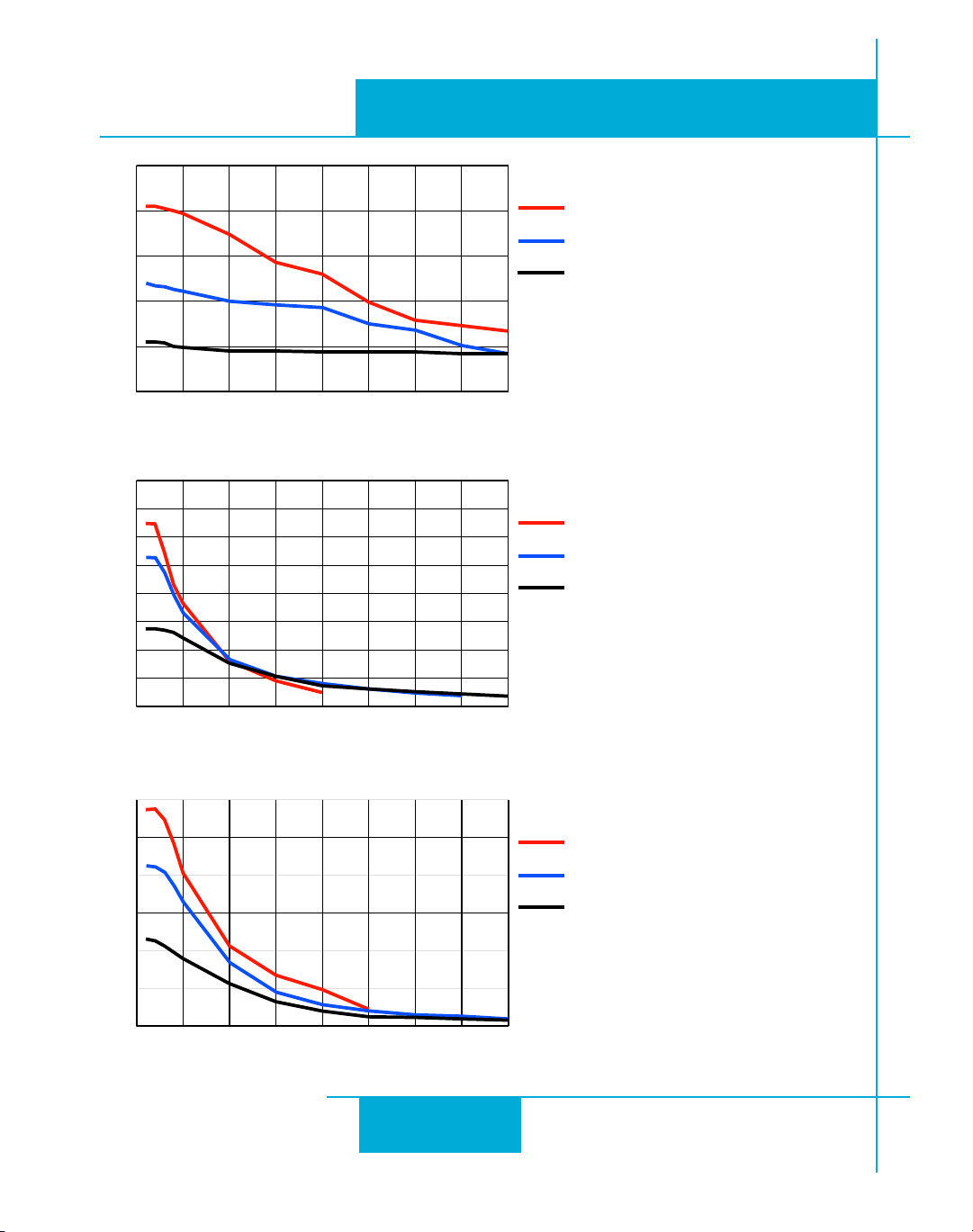
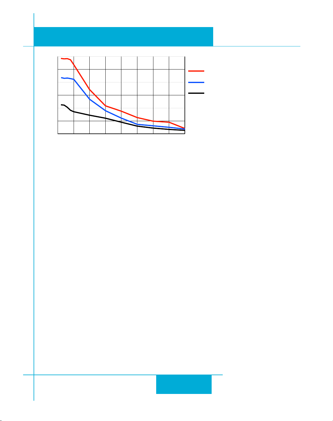
Torque-Speed Curves
Note: all torque curves were measured at 20,000 steps/rev.
4ORQUEOZIN
3PEEDREVSEC
2626
26
2626
6OLTS$#
!
(4!
(4!
Page 27
ST5/10-Si,-Q Hardware manualST5/10-Si,-Q Hardware manual
ST5/10-Si,-Q Hardware manual
ST5/10-Si,-Q Hardware manualST5/10-Si,-Q Hardware manual
920-0004 Rev. A4
5/707
4ORQUEOZIN
3PEEDREVSEC
4ORQUEOZIN
6OLTS$#
(4!
(4!
(4!
6OLTS$#
(4!
(4!
(4!
3PEEDREVSEC
4ORQUEOZIN
3PEEDREVSEC
2727
27
2727
6OLTS$#
(4!
(4!
(4!
Page 28
920-0004 Rev. A4
5/707
ST5/10-Si,-Q Hardware manualST5/10-Si,-Q Hardware manual
ST5/10-Si,-Q Hardware manual
ST5/10-Si,-Q Hardware manualST5/10-Si,-Q Hardware manual
4ORQUEOZIN
3PEEDREVSEC
4ORQUEOZIN
3PEEDREVSEC
6OLTS$#
(4!
(4!
(4!
6OLTS$#
(4!
(4!
(4!
4ORQUEOZIN
3PEEDREVSEC
2828
28
2828
6OLTS$#
(4
(4
(4
Page 29
ST5/10-Si,-Q Hardware manualST5/10-Si,-Q Hardware manual
ST5/10-Si,-Q Hardware manual
ST5/10-Si,-Q Hardware manualST5/10-Si,-Q Hardware manual
920-0004 Rev. A4
5/707
4ORQUELBIN
3PEEDREVSEC
6OLTS$#
(4
(4
(4
Motor Heating
Step motors convert electrical power from the driver into mechanical power to move a load.
Because step motors are not perfectly efficient, some of the electrical power turns into heat on its
way through the motor. This heating is not so much dependent on the load being driven but rather
the motor speed and power supply voltage. There are certain combinations of speed and voltage at
which a motor cannot be continuously operated without damage.
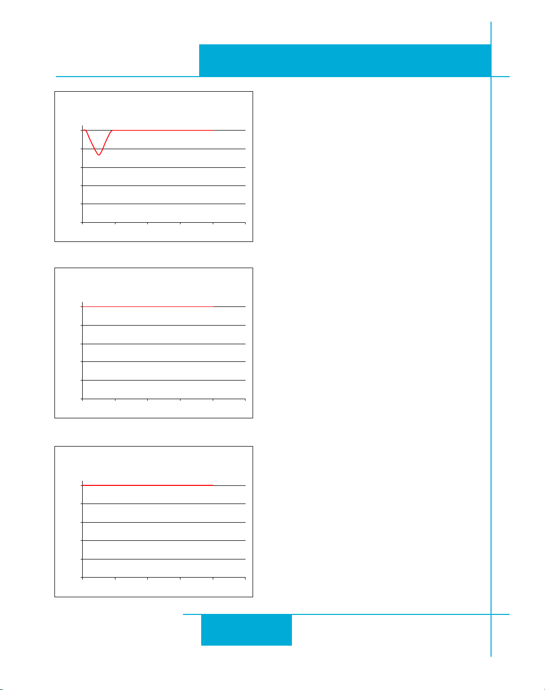
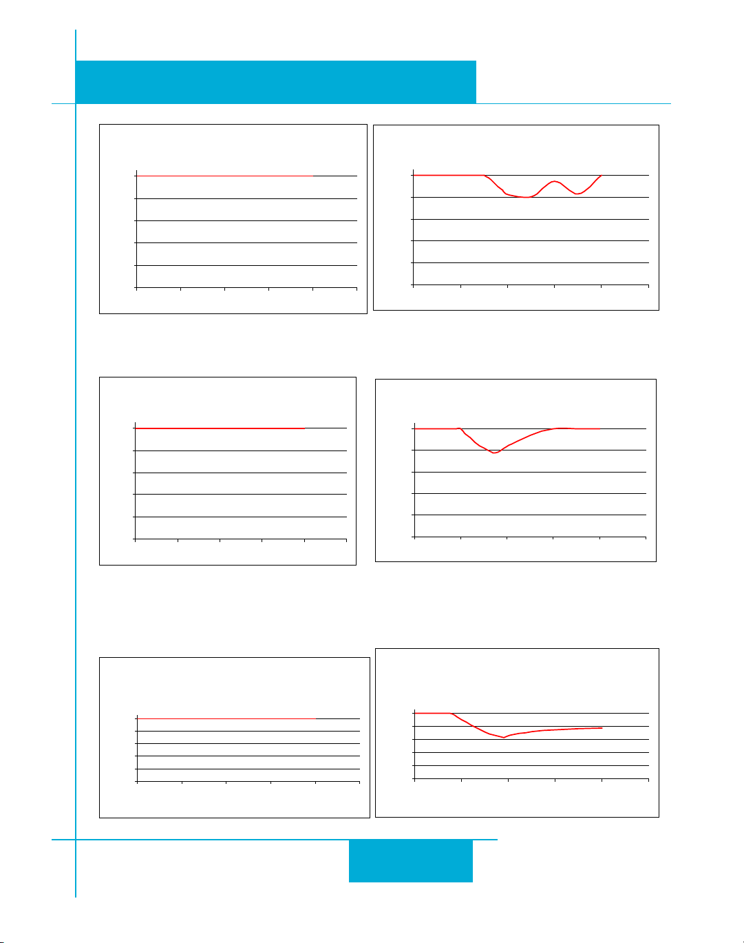
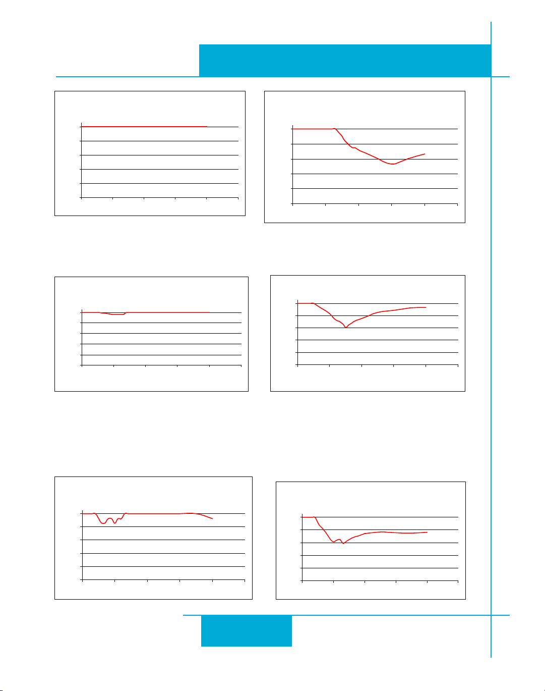
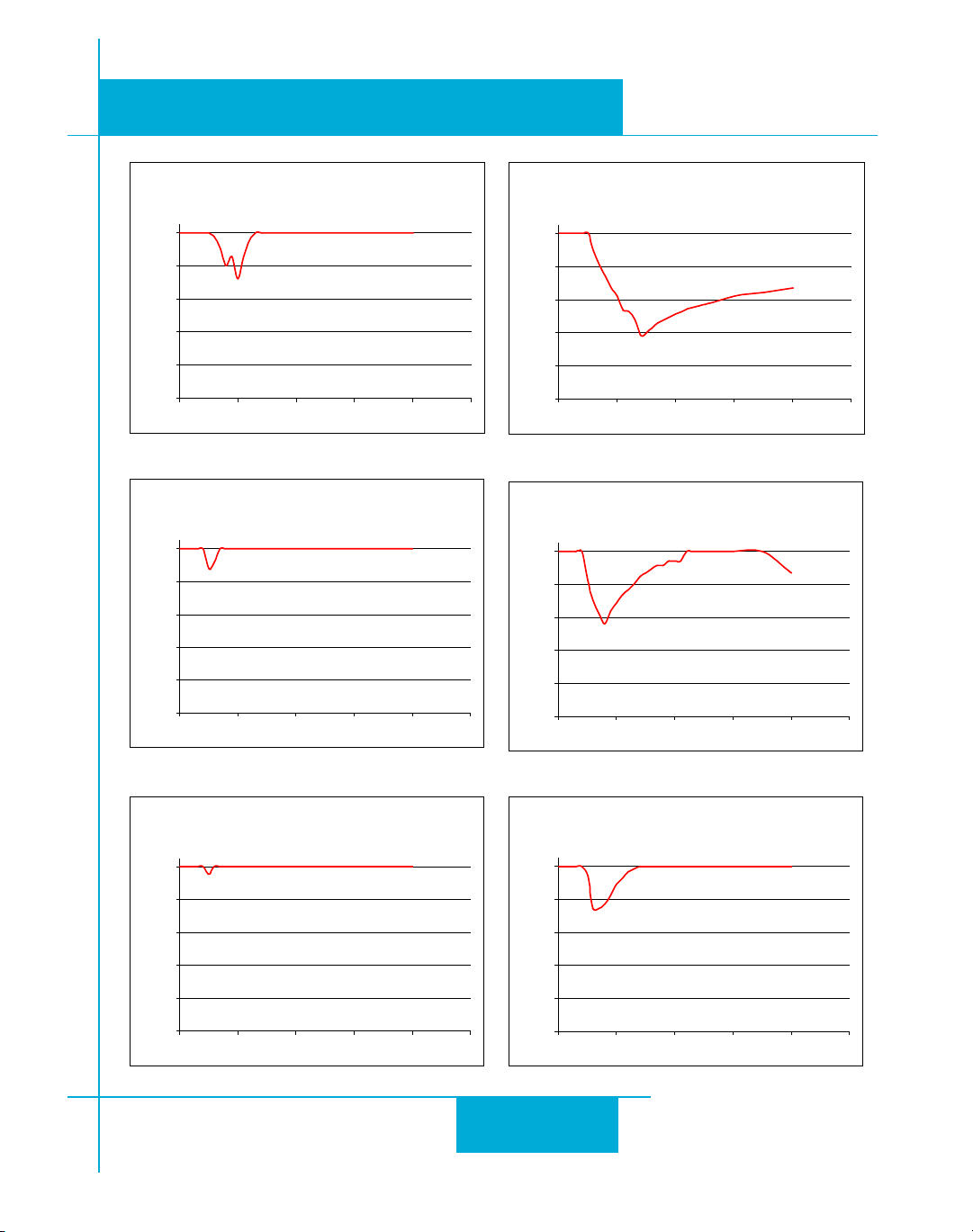
We have characterized the recommended motors in our lab and provided curves showing the
maximum duty cycle versus speed for each motor at commonly used power supply voltages.
Please refer to these curves when planning your application.
Please also keep in mind that a step motor typically reaches maximum temperature after 30 to 45
minutes of operation. If you run the motor for one minute then let it sit idle for one minute, that is a
50% duty cycle. Five minutes on and five minutes off is also 50% duty. However, one hour on and
one hour off has the effect of 100% duty because during the first hour the motor will reach full (and
possibly excessive) temperature.
The actual temperature of the motor depends on how much heat is conducted, convected or
radiated out of it. Our measurements were made in a 40°C (104°F) environment with the motor
mounted to an aluminum plate sized to provide a surface area consistent with the motor power
dissipation. Your results may vary.
2929
29
2929
Page 30
920-0004 Rev. A4
0D['XW\&\FOHYV6SHHG
9'&$&$PELHQW
0RXQWHGRQ[[$OXPLQXP3ODWH
6SHHG536
'XW\ &\FOH
+70D['XW\&\FOHYV6SHHG
9'&$&$PELHQW
0RXQWHGRQGLD[$OXPLQXP3ODWH
6SHHG536
'XW\ &\FOH
+70D['XW\&\FOHYV6SHHG
9'&$&$PELHQW
0RXQWHGRQGLD[$OXPLQXP3ODWH
6SHHG536
'XW\ &\FOH
5/707
ST5/10-Si,-Q Hardware manualST5/10-Si,-Q Hardware manual
ST5/10-Si,-Q Hardware manual
ST5/10-Si,-Q Hardware manualST5/10-Si,-Q Hardware manual
3030
30
3030
Page 31
ST5/10-Si,-Q Hardware manualST5/10-Si,-Q Hardware manual
+70D['XW\F\FOHYV6SHHG
9'&$PSV#&$PELHQW
RQ[[$OXPLQXP3ODWH
6SHHG536
'XW\&\FOH
+70D['XW\&\FOHYV6SHHG
9'&$PSV&$PELHQW
RQ[[$OXPLQXP3ODWH
6SHHG536
'XW\&\FOH
+70D['XW\&\FOHYV6SHHG
9'&$PSV&$PELHQW
RQ[[ $OX PLQXP3ODWH
6SHHG536
'XW\ &\FOH
+70D['XW\F\FOHYV6SHHG
9'&$PSV
&$PELH QW
RQ[[$OXPLQXP3ODWH
6SHHG536
'XW\&\FOH
+70D['XW\F\FOHYV6SHHG
9'&$PSV
&$PELH QW
RQ[[$OXPLQXP3ODWH
6SHHG536
'XW\&\FOH
+70D['XW\F\FOHYV6SHHG
9'&$PSV
&$PELH QW
RQ[[$OXPLQXP3ODWH
6SHHG536
'XW\&\FOH
ST5/10-Si,-Q Hardware manual
ST5/10-Si,-Q Hardware manualST5/10-Si,-Q Hardware manual
920-0004 Rev. A4
5/707
3131
31
3131
Page 32
920-0004 Rev. A4
+70D['XW\F\FOHYV6SHHG
9'&$PSV
&$PELH QW
RQ[[$OXPLQXP3ODWH
6SHHG536
'XW\&\FOH
+70D['XW\F\FOHYV6SHHG
6SHHG536
'XW\&\FOH
+70D['XW\F\FOHYV6SHHG
9'&$PSV
&$PELH QW
RQ[[$OXPLQXP3ODWH
6SHHG536
'XW\&\FOH
+70D['XW\&\FOHYV6SHHG
9'&$PSV& $PELH QW
RQ[[$OXPLQXP3ODWH
6SHHG536
'XW\ &\FOH
+70D['XW\F\FOHYV6SHHG
9'&$&$PELHQW
RQ[[$OXPLQXP3ODWH
6SHHG536
'XW\&\FOH
+70D['XW\&\FOHYV6SHHG
9'&$PS V&$PELHQW
RQ[[$OXPLQXP3ODWH
6SHHG536
'XW\ &\FOH
5/707
ST5/10-Si,-Q Hardware manualST5/10-Si,-Q Hardware manual
ST5/10-Si,-Q Hardware manual
ST5/10-Si,-Q Hardware manualST5/10-Si,-Q Hardware manual
9'&$&$PELHQW
RQ[[$OXPLQXP3ODWH
3232
32
3232
Page 33
ST5/10-Si,-Q Hardware manualST5/10-Si,-Q Hardware manual
+70D['XW\&\FOHYV6SHHG
9'&$PSV&$PELHQW
RQ[[$OXPLQXP3ODWH
6SHHG536
'XW\ &\FOH
+70D['XW\F\FOHYV6SHHG
9'&$PSV
&$PELH QW
RQ[[$OXPLQXP3ODWH
6SHHG536
'XW\&\FOH
+70D['XW\&\FOHYV6SHHG
9'&$PSV&$PELHQW
RQ[[$OXPLQXP3ODWH
6SHHG536
'XW\ &\FOH
+70D['XW\F\FOHYV6SHHG
9'&$PSV&$PE LHQW
RQ[[$OXPLQXP3ODWH
6SHHG536
'XW\&\FOH
+70D['XW\F\FOHYV6SHHG
9'&$PSV
&$PELH QW
RQ[[$OXPLQXP3ODWH
6SHHG536
'XW\&\FOH
+70D['XW\F\FOHYV6SHHG
9'&$PSV
&$PELH QW
RQ[[$OXPLQXP3ODWH
6SHHG536
'XW\&\FOH
ST5/10-Si,-Q Hardware manual
ST5/10-Si,-Q Hardware manualST5/10-Si,-Q Hardware manual
920-0004 Rev. A4
5/707
3333
33
3333
Page 34
920-0004 Rev. A4
5/707
ST5/10-Si,-Q Hardware manualST5/10-Si,-Q Hardware manual
ST5/10-Si,-Q Hardware manual
ST5/10-Si,-Q Hardware manualST5/10-Si,-Q Hardware manual
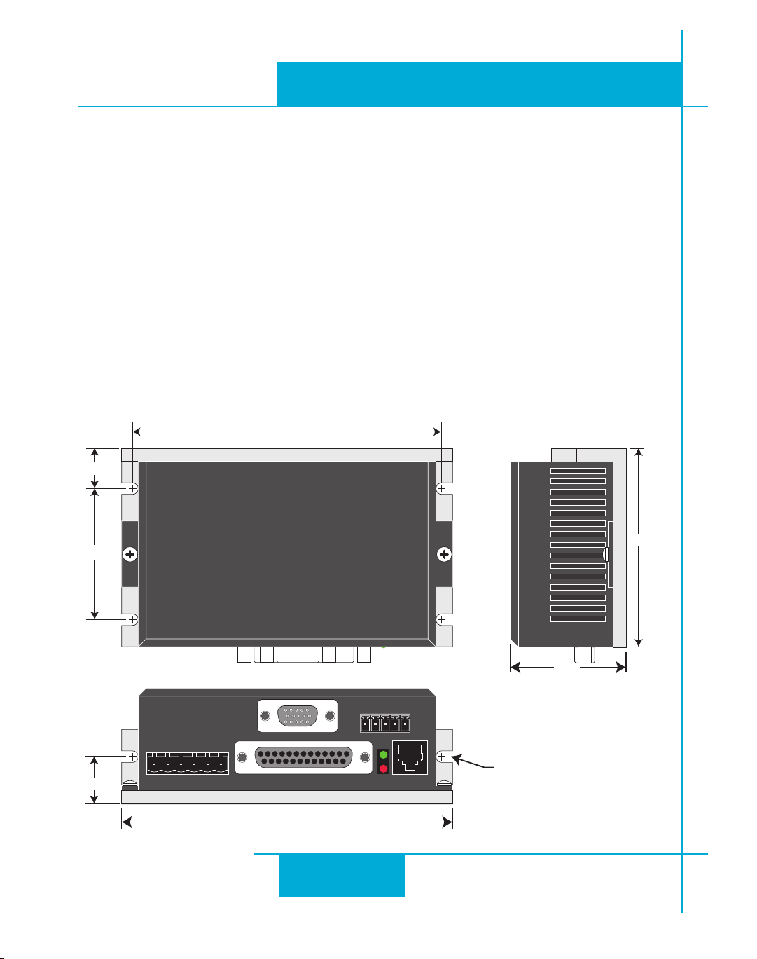
Mounting the Drive
You can mount your drive on the wide or the narrow side of the chassis using #6 screws. If
possible, the drive should be securely fastened to a smooth, flat metal surface that will help
conduct heat away from the chassis. If this is not possible, then forced airflow from a fan may be
required to prevent the drive from overheating.
•
Never use your drive in a space where there is no air flow or where other devices
cause the surrounding air to be more than 40°C.
•
Never put the drive where it can get wet or where metal or other electrically
conductive particles can get on the circuitry.
•
Always provide air flow around the drive. When mouting multiple ST drives near
each other, maintain at least one half inch of space between drives.
Mechanical Outline
3434
34
3434
83,/4
7)$%&5,,2
Page 35

ST5/10-Si,-Q Hardware manualST5/10-Si,-Q Hardware manual
ST5/10-Si,-Q Hardware manual
ST5/10-Si,-Q Hardware manualST5/10-Si,-Q Hardware manual
Technical Specifications
920-0004 Rev. A4
5/707
Amplifier
Digital Inputs
Analog Inputs
Outputs
Physical
Digital MOSFET. 16 kHz PWM.
ST5: 18 - 53 VDC, motor current: 0.5 to 5.0 amps/phase peak of sine
ST10: 18 - 88 VDC, motor current: 0.5 to 10 amps/phase peak of sine
Step & Direction: differential, optically isolated, 5V logic. 330 ohms internal
resistance.
0.5 µsec minimum pulse width. 2 µsec minimum set up time for direction
signal.
All other digital inputs: optically isolated, 12 - 24V logic. 2200 ohms.
Maximum current: 10 mA.
±10VDC, 12 bit ADC, 100k ohms internal impedance.
Photodarlington, 100 mA, 30 VDC max. Voltage drop: 1.2V max at 100 mA.
1.775 x 3 x 5 inches overall. 10 oz (280 g)
Ambient temperature range: 0°C to 40°C.
Mating Connectors and Accessories
Mating Connectors
Motor/power supply: PCD P/N ELV06100, included with drive.
IN/OUT1: DB-25 male. AMP P/N 747912-2. Shell Kit AMP P/N748678-3. Included.
Optional encoder feedback: HD-15 male. Norcomp P/N 180-015-102-001. Shell Kit AMP P/N
748678-1. Not included.
3535
35
3535
Page 36

920-0004 Rev. A4
5/707
Accessories
Breakout Box for DB-25 Connector
BOB-1, includes cable
Screw Terminal Connectors that mate directly to the DB-25 connector on the front panel of the
drive:
Phoenix Contact P/N 2761622
This connector is not available from Applied Motion. You must purchase it from a
Phoenix distributor.
Mating Cable for IN/OUT connector with “flying leads”
Black Box P/N: BC00702
This cable is not available from Applied Motion. You must purchase it from Black Box.
Useful for custom wired applications. This shielded cable has a DB-25 connector on each
end. You can cut off the female end to create a 6 foot “DB-25 to flying lead cable”.
It’ll be easier to wire if you get the cable color chart from Black Box’s web site.
ST5/10-Si,-Q Hardware manualST5/10-Si,-Q Hardware manual
ST5/10-Si,-Q Hardware manual
ST5/10-Si,-Q Hardware manualST5/10-Si,-Q Hardware manual
Regeneration Clamp:
Applied Motion Products RC050.
Operator Terminal (-Si drives only)
Applied Motion Products MMI-01 or MMI-02 (backlit).
3636
36
3636
Page 37
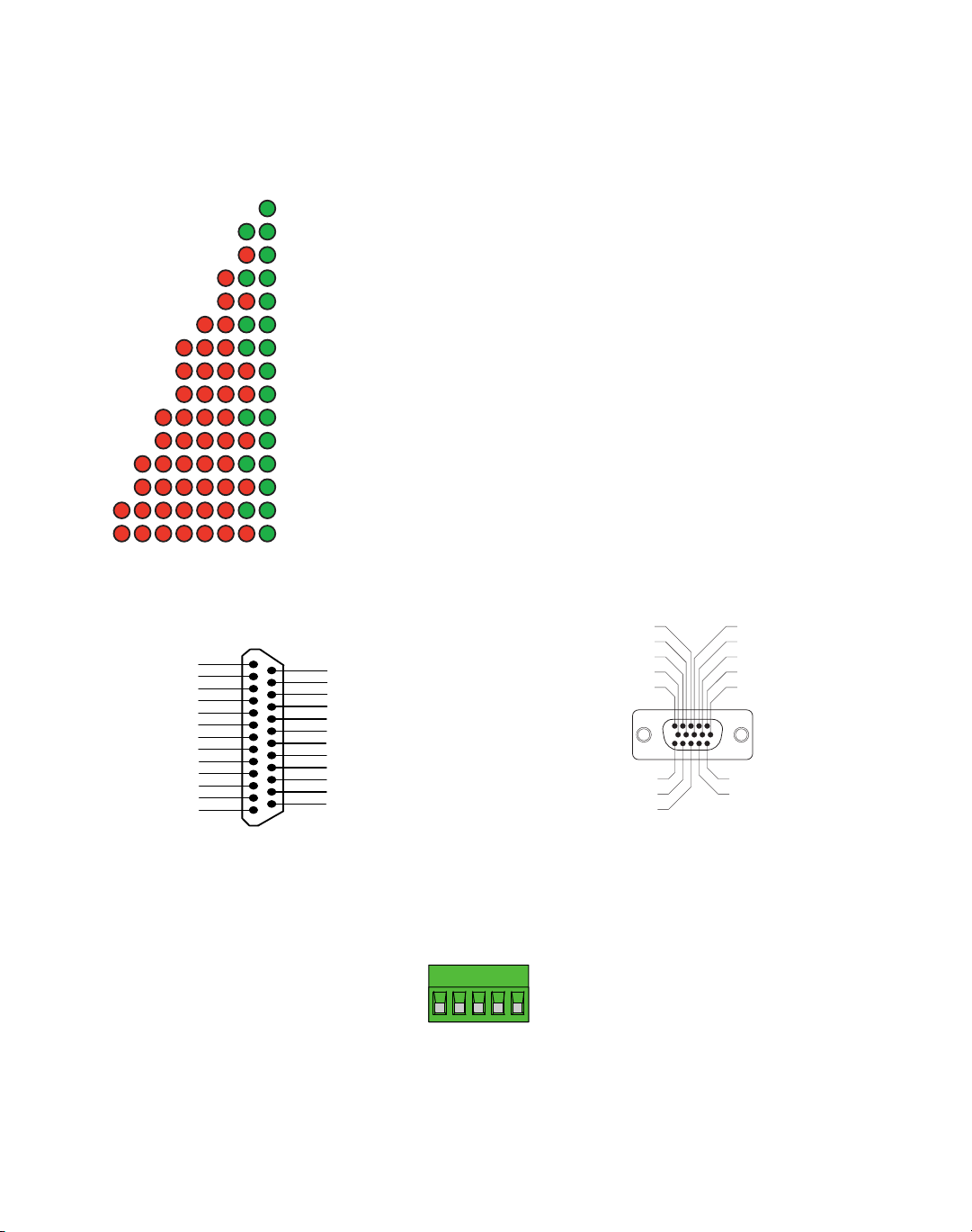
Alarm Codes
In the event of an error, the green LED on the main board will flash one or two times, followed by a series of red flashes. The
pattern repeats until the alarm is cleared.
&RGH (UURU
VROLGJUHHQ QRDODUPPRWRUGLVDEOHG
IODVKLQJJUHHQ QRDODUPPRWRUHQDEOHG
UHGJUHHQPRWRUVWDOORSWLRQDOHQFRGHURQO\
UHGJUHHQ PRYHDWWHPSWHGZKLOHGULYHGLVDEOHG
UHGJUHHQFFZOLPLW
UHGJUHHQFZOLPLW
UHGJUHHQGULYHRYHUKHDWLQJ
UHGJUHHQ LQWHUQDOYROWDJHRXWRIUDQJH
UHGJUHHQSRZHUVXSSO\RYHUYROWDJH
UHGJUHHQSRZHUVXSSO\XQGHUYROWDJH
UHGJUHHQRYHUFXUUHQWVKRUWFLUFXLW
UHGJUHHQ PRWRUUHVLVWDQFHRXWRIUDQJH
UHGJUHHQRSHQPRWRUZLQGLQJ
UHGJUHHQEDGHQFRGHUVLJQDORSWLRQDOHQFRGHURQO\
UHGJUHHQVHULDOFRPPXQLFDWLRQHUURU
Connector Diagrams
'.$
ENCODER!
6$#M!
ENCODER!
ENCODER:
DONOTCONNECT
DONOTCONNECT
Ww}_dG
Ww}_dH
nLEYYm`e]
nKEYm`e]
nJEWwh{{
nIE[wx{
nYecced
nHEZ_hC
nHEZ_hA
nGEij[fC
nGEij[fA
]dZ
)./54
1
2
3
4
5
6
7
8
9
10
11
12
13
&RONT6IEW
14
15
16
17
18
19
20
21
22
23
24
25
oGEXhWa[
oHEcej_ed
oIE\Wkbj
oYecced
AKlekj
]dZ
oJA
oJC
nMEYmb_c_jA
nMEYmb_c_jC
nNEYYmb_c_jA
nNEYYmb_c_jC
ENCODER"
DONOTCONNECT
ENCODER"
DONOTCONNECT
ENCODER:
SHIELD
DONOTCONNECT
DONOTCONNECT
`p
DB-25 I/O Connector HD-15 Encoder Connector
RS-485/422
RX+
RX
–
TX+
TX
–
GND
Applied Motion Products, Inc.
404 Westridge Drive Watsonville, CA 95076
Tel (831) 761-6555 (800) 525-1609 Fax (831) 761-6544
www.appliedmotionproducts.com
 Loading...