

Page 1
• ST5-Q • ST10-Q
ST
Re-Order from
omegamation.com
Omegamation
TM
1-888-55-OMEGA
1-888-55-66342
1-888-55-66342
• ST5-Q-E • ST10-Q-E
• ST5-Si • ST10-Si
• ST5-C • ST10-C
• ST5-IP-E • ST10-IP-E
920-0004 Rev. C
4/21/11
Page 2

920-0004 Rev. C
4/21/11
ST5/10-Si,-Q,-C, -IP Hardware manual
Contents
Introduction...............................................................................................................................................................................3
Features
....................................................................................................................................................................................3
Block Diagrams
Getting Started ..........................................................................................................................................................................6
Connecting to the PC using RS-232
Connecting the Drive to Your PC using Ethernet
Addresses, Subnets, and Ports
Option 1: Connect a Drive to Your Local Area Network
Option 2: Connect a Drive Directly to Your PC ................................................................................................................14
Option 3: Use Two Network Interface Cards (NICs) .........................................................................................................16
Connecting to a host using RS-485 option card......................................................................................................................17
RS-232 to RS-485 2-wire Converter ................................................................................................................................18
Converting USB to RS-485 ..............................................................................................................................................18
Connecting the Power Supply .................................................................................................................................................20
Connecting the Motor .............................................................................................................................................................21
Connecting an Encoder (Requires the optional Encoder Feedback Card)
Connecting Input Signals
Connector Pin Diagram ....................................................................................................................................................23
High Speed Digital Inputs ................................................................................................................................................24
Connecting a Potentiometer to Analog Input 1 .................................................................................................................31
Programmable Outputs ...........................................................................................................................................................32
Sinking Output .................................................................................................................................................................32
Using Y1, Y2, Y3 ..............................................................................................................................................................32
Sinking Output .................................................................................................................................................................32
Sourcing Output ...............................................................................................................................................................33
Driving a Relay .................................................................................................................................................................33
Choosing a Power Supply .......................................................................................................................................................34
Recommended Motors ............................................................................................................................................................35
Torque-Speed Curves..............................................................................................................................................................35
Motor Heating .........................................................................................................................................................................38
Mounting the Drive .................................................................................................................................................................43
Mechanical Outline .................................................................................................................................................................43
Technical Specifications ..........................................................................................................................................................44
Mating Connectors and Accessories .......................................................................................................................................45
Alarm Codes ...........................................................................................................................................................................46
Connector Diagrams ...............................................................................................................................................................46
.........................................................................................................................................................................4
.........................................................................................................................................8
.......................................................................................................................9
...........................................................................................................................................9
....................................................................................................11
Using DCHP ..............................................................................................................................................................13
................................................................................22
........................................................................................................................................................23
2
Page 3

920-0004 Rev. C
ST5/10-Si,-Q,-C, IP Hardware manual
4/21/11
Introduction
Thank you for selecting an Applied Motion Products motor control. We hope our dedication to performance,
quality and economy will make your motion control project successful.
If there’s anything we can do to improve our products or help you use them better, please call or fax. We’d
like to hear from you. Our phone number is (800) 525-1609, or you can reach us by fax at (831) 761-6544.
You can also email [email protected].
Features
• Programmable, microstepping digital step motor driver in compact package
• ST5 operates from a 24 to 48 volt DC power supply
• ST10 operates from a 24 to 80 volt DC power supply
• Operates in velocity or position mode
• Accepts analog signals, digital signals and RS-232 serial commands
• Optional RS-422/485 communication
• Optional encoder feedback
• Optional CANopen DSP402 Control
• Optional CANopen DS301 communication with DS402 motion control
• Optional 100 Mbit Ethernet communication using SCL and Q
• Optional Ethernet/IP protocol communication
• ST5 provides motor current up to 5 amps/phase (peak of sine)
• ST10 provides motor current up to 10 amps/phase (peak of sine)
• Eight optically isolated digital inputs
• Four optically isolated digital outputs
• Two ±10 volt analog inputs for speed and position control. Can also be congured for 0 to
10V, ±5V or 0 to 5V signal ranges.
3
Page 4
920-0004 Rev. C
motor
encoder
24 - 48 VDC*
INPUT X1
INPUT X2
INPUT X3
INPUT X4
INPUT X5
INPUT X6
X7/CWLIM
*24 - 80 VDC for ST10
to PC/MMI
RS-485
X8/CCWLIM
OUTPUT Y1
OUTPUT Y2
OUTPUT Y3
OUTPUT Y4
ANALOG IN2
ANALOG IN1
DSP
Optical
Isolation
Si™
Chip
RS-232
Option Card
Option Card
MOSFET
PWM
Power
Amplifier
Internal
Logic
Supply
Status
motor
encoder
24 - 48 VDC*
INPUT X1
INPUT X2
INPUT X3
INPUT X4
INPUT X5
INPUT X6
X7/CWLIM
*24 - 80 VDC for ST10
to PC/MMI
X8/CCWLIM
OUTPUT Y1
OUTPUT Y2
OUTPUT Y3
OUTPUT Y4
ANALOG IN2
ANALOG IN1
DSP
Optical
Isolation
RS-232
Option Card
MOSFET
PWM
Power
Amplifier
Internal
Logic
Supply
Status
CANopen
(Required on ST-C Drives only)
or RS485
(Optional on ST-Q Drives only)
Option Card
4/21/11
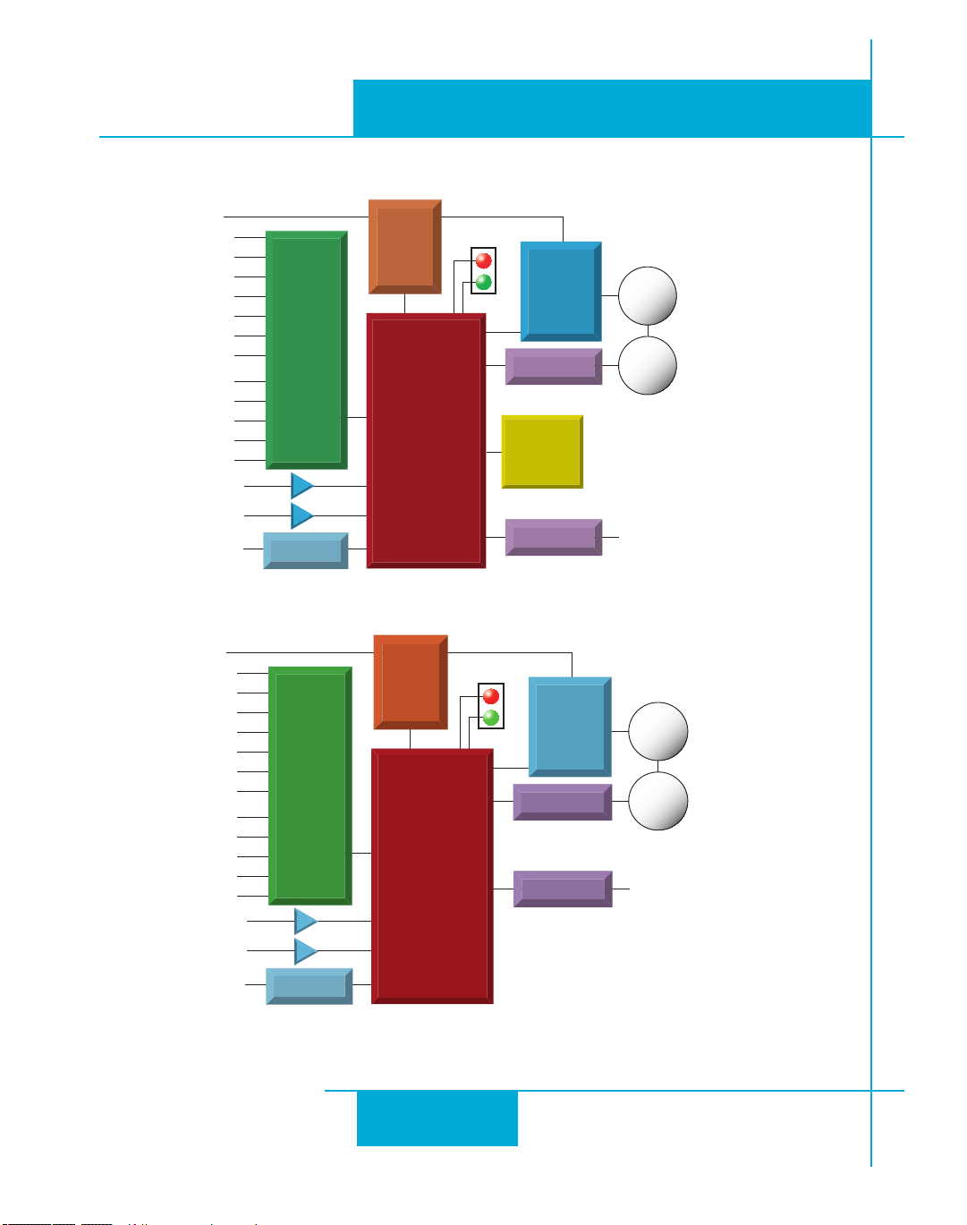
Block Diagrams
ST5/10-Si,-Q,-C, -IP Hardware manual
ST5-Si and ST10-Si
ST5-Q, ST5-C, ST10-Q and ST10-C
4
Page 5
ST5/10-Si,-Q,-C, IP Hardware manual
920-0004 Rev. C
4/21/11
24 - 48 VDC*
INPUT X1
INPUT X2
INPUT X3
INPUT X4
INPUT X5
INPUT X6
X7/CWLIM
X8/CCWLIM
OUTPUT Y1
OUTPUT Y2
OUTPUT Y3
OUTPUT Y4
ANALOG IN1
ANALOG IN2
not used
*24 - 80 VDC for ST10
Internal
Logic
Supply
Status
MOSFET
PWM
Power
Amplifier
Optical
Isolation
Option Card
encoder
DSP
Ethernet
Option Card
RS-232
to Ethernet switch
or network interface
card
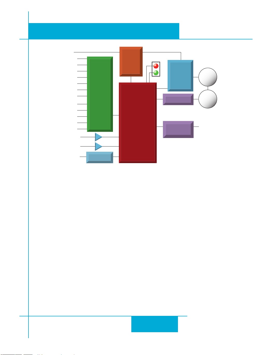
ST5-Q-EN, ST5-Q-EE, ST5-IP-EN, ST5-IP-EE,
ST10-Q-EN, ST10-Q-EE, ST10-IP-EN, ST10-IP-EE
motor
5
Page 6

920-0004 Rev. C
4/21/11
ST5/10-Si,-Q,-C, -IP Hardware manual
Getting Started
This manual describes the use of six different drive models. What you need to know and what you must
have depends on the drive model. For all models, you’ll need the following:
• a 24-48 volt DC power supply. (24 - 80VDC for ST10 models). Please read the
section entitled Choosing a Power Supply for help in choosing the right power supply.
• a compatible step motor. See section on Recommended Motors.
• a small at blade screwdriver for tightening the connectors (included).
• a personal computer running Microsoft Windows 98, 2000, NT, Me, XP, Vista or 7.
• An Applied Motion programming cable (included with non-Ethernet drives).
• For Ethernet drives you will need a CAT5 cable (not included).
• Relevant software applications, as outlined below. All software is available as a free download from
http://www.applied-motion.com/products/software.
If you’ve never used an ST drive before you’ll need to get familiar with the drive and the set up software
before you try to deploy the system in your application. We strongly recommend the following:
1. For -S drives, install the ST Configurator™ software application.
For -Q drives, install the ST Configurator™ and Q Programmer™ software applications.
For -Q-E and -IP-E drives, install ST Configurator Ethernet™ and Q Programmer™ software applications.
For -Si models, install and use the Si Programmer™ software for configuration and programming.
For -C drives, install the ST Configurator™ and the CANopen Example Program software applications.
Q Programmer™ software may also be installed, if needed.
2. Launch the software by clicking Start...Programs...Applied Motion...
3. Connect the drive to your PC using the programming cable. For RS-232 drives, select the correct COM
port. For Ethernet drives, ensure that the IP address is correct.
4. Connect the drive to the power supply.
5. Connect the drive to the motor.
6. Apply power to the drive.
7. The software will recognize your drive, display the model and firmware version and be ready for action.
6
Page 7
920-0004 Rev. C
B-
B+
A-
A+
V-
V+
B-
B+
A-
A+
V-
V+
LED Codes
GR=Green
RD=Red
MOTOR DISABLED SOLID GREEN
MOTOR ENABLED GR-GR-GR
MOTOR STALL 1 GR + 1 RD
CCW LIMIT 1 GR + 2 RD
CW LIMIT 2 GR + 2 RD
CAN’T MOVE (DISABLED) 2 GR + 1 RD
DRIVE OVER TEMP 1 GR + 3 RD
VOLTAGE HIGH 1 GR + 4 RD
VOLTAGE LOW 2 GR + 4 RD
OVER CURRENT 1 GR + 5 RD
MOTOR OHMS 2 GR + 5 RD
OPEN MOTOR PHASE 1 GR + 6 RD
BAD ENCODER SIGNAL 2 GR + 6 RD
COMM ERROR 1 GR + 7 RD
GND
+5V OUT
Y COMMON
Y3 / FAULT
Y2 / MOTION
Y1 / BRAKE
X8 / CCWLIMIT+
X8 / CCWLIMIT -
X7 / CWLIMIT -
X7 / CWLIMIT+
Y4 -
Y4+
25
24
23
22
21
20
19
18
17
16
15
14
13
12
11
10
9
8
7
6
5
4
3
2
1
X COMMON
X3 / ENABLE
X5 / CWJOG
X4 / ALARM RESET
ANALOG IN2
ANALOG IN1
X2 / DIR -
X2 / DIR+
X1 / STEP+
X1 / STEP -
GND
X6 / CCWJOG
Serial No
ST5- Q
STEP MOTOR
DRIVER
screw terminal
connector
• motor
• power supply
DB-25 connector
• digital inputs
• digital outputs
• analog input
screw terminal
connector
• optional RS-485 port
HD-15 connector
• optional encoder feedback
RJ11 connector
• RS-232 port
LEDs
• status & error codes
grounding
screw
spring terminal
connector
and rotary switches
• optional CANopen interface
RJ45 connector and
rotary address switch
• optional Ethernet interface
ST5/10-Si,-Q,-C, IP Hardware manual
4/21/11
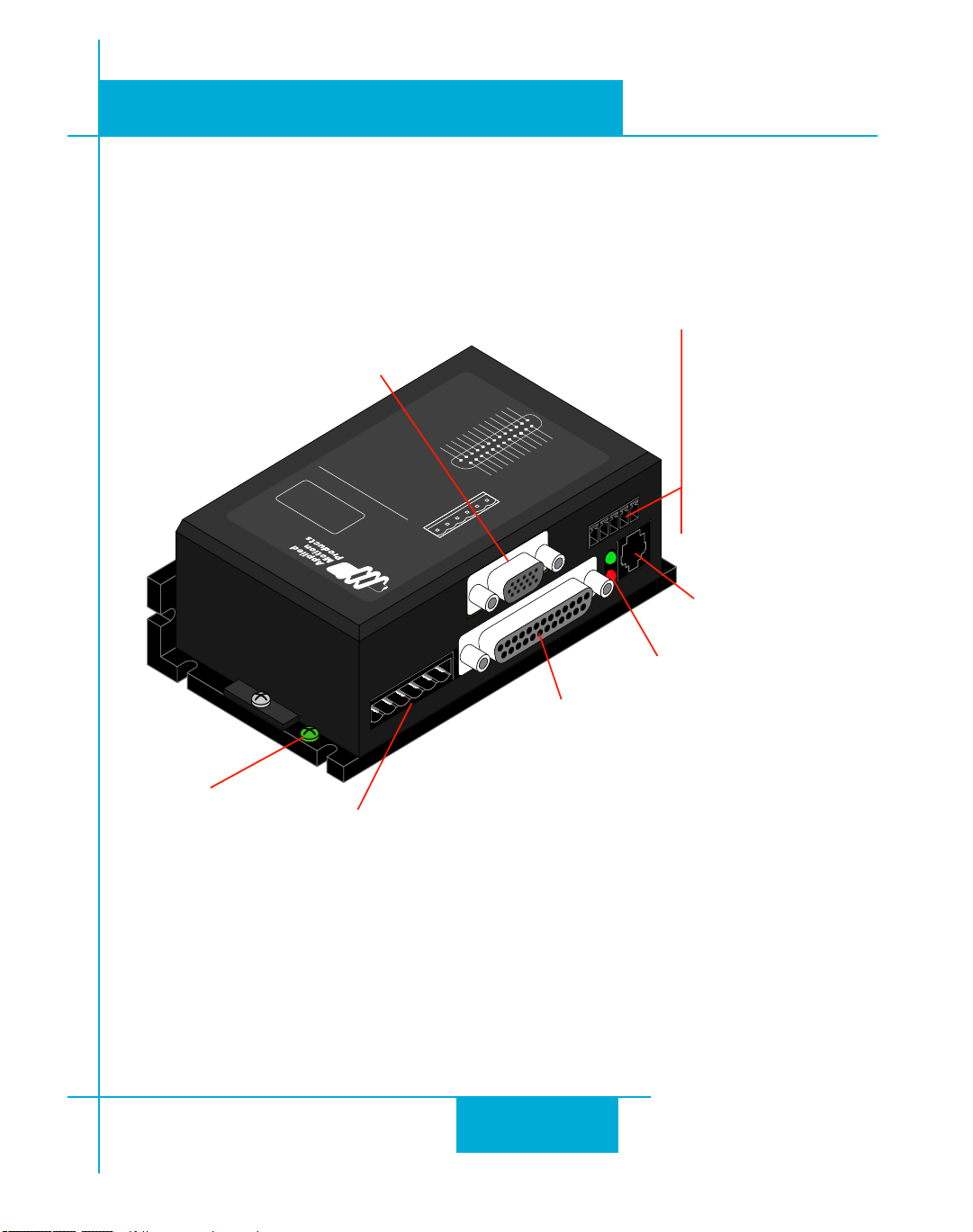
The connectors and other points of interest are illustrated below. Depending on your drive model and application, you’ll need to make connections to various parts of the drive. These are detailed later in the manual.
7
Page 8
920-0004 Rev. C
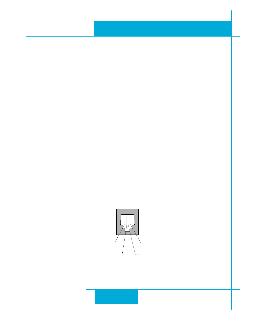
ground (to PC ground)
TX (to PC RX)
No connection
RX (to PC TX)
4/21/11
ST5/10-Si,-Q,-C, -IP Hardware manual
Connecting to the PC using RS-232
• Locate your computer within 8 feet of the drive.
• If you have a CANopen drive, you still need to connect to the RS232 port on your PC to congure the
drive and download Q Programs, if necessary. Once conguration is complete, refer to the CANopen Manual
for information on using your CANopen drive.
• If you have an Ethernet drive, this port is not used. All communcation uses the RJ45 Ethernet connector
• RS-232 drives are shipped with a communication cable. Plug the large end into the serial port of your PC
and the small end into the PC/MMI jack on your drive. Secure the cable to the PC with the screws on the
sides.
Never connect a drive to a telephone circuit. It uses the same connectors and cords as
telephones and modems, but the voltages are not compatible.
If your PC does not have a serial port, you should purchase a “USB Serial Converter”. We have had good
results with the USB-COM-CBL from byterunner.com. If you wish to use a different converter, it is recommended to use one that makes use of the FTDI chipset to perform the actual conversion.
.
Pin Assignments of the PC/MMI Port
(RJ11 connector)
8
Page 9

920-0004 Rev. C
ST5/10-Si,-Q,-C, IP Hardware manual
Connecting the Drive to Your PC using Ethernet
This process requires three steps
• Physically connect the drive to your network (or directly to the PC)
• Set the drive’s IP address
• Set the appropriate networking properties on your PC.
Note: the following pages are an excerpt from the “eSCL Communication Reference Guide”. For more
information, please read the rest of the guide.
Addresses, Subnets, and Ports
Every device on an Ethernet network must have a unique IP address. In order for two devices to communicate with each other, they must both be connected to the network and they must have IP addresses that are
on the same subnet. A subnet is a logical division of a larger network. Members of one subnet are generally not able to communicate with members of another unless they are connected through special network
equipment (e.g. router). Subnets are defined by the choices of IP addresses and subnet masks.
If you want to know the IP address and subnet mask of your PC, select Start…All Programs…Accessories…Command Prompt. Then type “ipconfig” and press Enter. You should see something like this:
4/21/11
If your PC’s subnet mask is set to 255.255.255.0, a common setting known as a Class C subnet mask, then
your machine can only talk to another network device whose IP address matches yours in the first three
octets. (The numbers between the dots in an IP address are called octets.) For example, if your PC is on a
Class C subnet and has an IP address of 192.168.0.20, it can talk to a device at 192.168.0.40, but not one at
192.168.1.40. If you change your subnet mask to 255.255.0.0 (Class B) you can talk to any device whose
first two octets match yours. Be sure to ask your system administrator before doing this. You network may
be segmented for a reason.
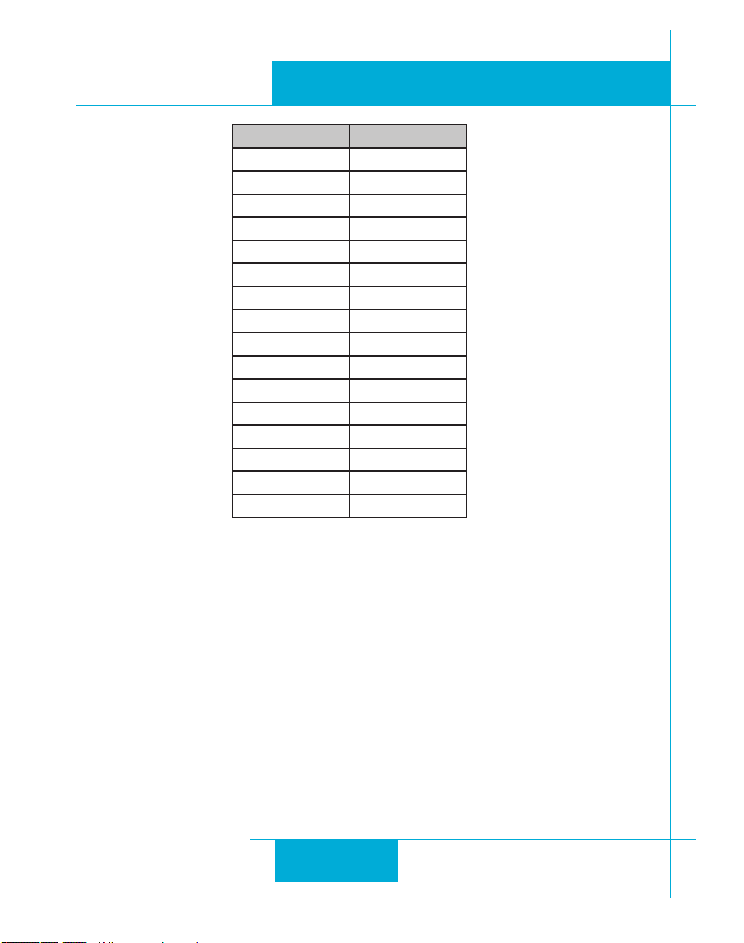
Your drive includes a 16 position rotary switch for setting its IP address. The factory default address for
each switch setting is shown in the table on the next page.
9
Page 10
920-0004 Rev. C
4/21/11
ST5/10-Si,-Q,-C, -IP Hardware manual
Rotary Switch IP Address
0 10.10.10.10
1 192.168.1.10
2 192.168.1.20
3 192.168.1.30
4 192.168.0.40
5 192.168.0.50
6 192.168.0.60
7 192.168.0.70
8 192.168.0.80
9 192.168.0.90
A 192.168.0.100
B 192.168.0.110
C 192.168.0.120
D 192.168.0.130
E 192.168.0.140
F DHCP
Settings 1 through E can be changed using the ST Congurator software (use Quick Tuner for servo drives).
Setting 0 is always “10.10.10.10”, the universal recovery address. If someone were to change the other
settings and not write it down or tell anyone (I’m not naming names here, but you know who I’m talking
about) then you will not be able to communicate with your drive. The only way to “recover” it is to use the
universal recovery address.
Setting F is “DHCP”, which commands the drive to get an IP address from a DHCP server on the network.
The IP address automatically assigned by the DHCP server may be “dynamic” or “static” depending on how
the administrator has configured DHCP. The DHCP setting is reserved for advanced users.
Your PC, or any other device that you use to communicate with the drive, will also have a unique address.
On the drive, switch settings 1 through E use the standard class B subnet mask (i.e. “255.255.0.0”). The
mask for the universal recovery address is the standard class A (i.e. “255.0.0.0”).
One of the great features of Ethernet is the ability for many applications to share the network at the same
10
Page 11
920-0004 Rev. C
ST5/10-Si,-Q,-C, IP Hardware manual
time. Ports are used to direct traffic to the right application once it gets to the right IP address. The UDP
eSCL port in our drives is 7775. To send and receive commands using TCP, use port number 7776. You’ll
need to know this when you begin to write your own application. You will also need to choose an open
(unused) port number for your application. Our drive doesn’t care what that is; when the first command is
sent to the drive, the drive will make note of the IP address and port number from which it originated and
direct any responses there. The drive will also refuse any traffic from other IP addresses that is headed for
the eSCL port. The first application to talk to a drive “owns” the drive. This lock is only reset when the drive
powers down.
If you need help choosing a port number for your application, you can find a list of commonly used port
numbers at http://www.iana.org/assignments/port-numbers.
One final note: Ethernet communication can use one or both of two “transport protocols”: UDP and TCP.
eSCL commands can be sent and received using either protocol. UDP is simpler and more efficient than
TCP, but TCP is more reliable on large or very busy networks where UDP packets might occasionally be
dropped.
4/21/11
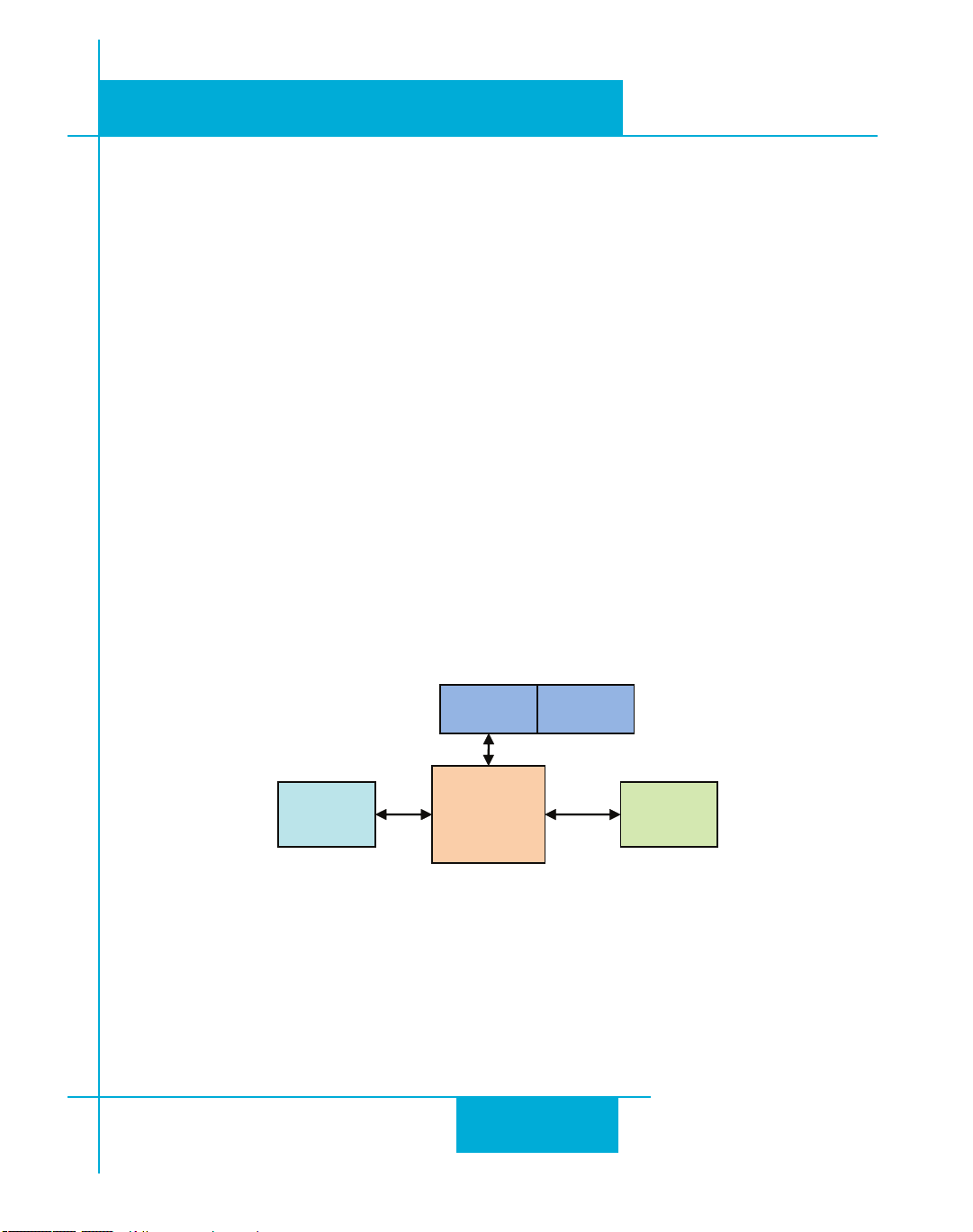
Option 1: Connect a Drive to Your Local Area Network
If you have a spare port on a switch or router and if you are able to set your drive to an IP address that is
compatible with your network, and not used by anything else, this is a simple way to get connected. This
technique also allows you to connect multiple drives to your PC. If you are on a corporate network, please
PC NIC
SWITCH
LAN DRIVE
check with your system administrator before connecting anything new to the network. He or she should be
able assign you a suitable address and help you get going.
If you are not sure which addresses are already used on your network, you can find out using “Angry IP
scanner”, which can be downloaded free from http://www.angryip.org/w/Download. But be careful: an
address might appear to be unused because a computer or other device is currently turned off. And many
networks use dynamic addressing where a DHCP server assigns addresses “on demand”. The address you
choose for your drive might get assigned to something else by the DHCP server at another time.
or
ROUTER
11
Page 12

920-0004 Rev. C
4/21/11
Once you’ve chosen an appropriate IP address for your drive, set the rotary switch according the address
table above. If none of the default addresses are acceptable for your network, you can enter a new table of IP
addresses using Configurator. If your network uses addresses starting with 192.168.0, the most common
subnet, you will want to choose an address from switch settings 4 through E. Another common subnet is
192.168.1. If your network uses addresses in this range, the compatible default selections are 1, 2 and 3.
If your PC address is not in one of the above private subnets, you will have to change your subnet mask to
255.255.0.0 in order to talk to your drive. To change your subnet mask:
ST5/10-Si,-Q,-C, -IP Hardware manual
1. On Windows XP, right click on “My Network Places” and select properties. On Windows 7, click
Computer. Scroll down the left pane until you see “Network”. Right click and select properties. Select
“Change adapter settings”
2. You should see an icon for your network interface card (NIC). Right click and select properties.
3. Scroll down until you see “Internet Properties (TCP/IP)”. Select this item and click the Properties button. On Windows 7 and Vista, look for “(TCP/IPv4)”
4. If the option “Obtain an IP address automatically” is selected, your PC is getting an IP address and a
subnet mask from the DHCP server. Please cancel this dialog and proceed to the next section of this
12
Page 13

920-0004 Rev. C
ST5/10-Si,-Q,-C, IP Hardware manual
manual: “Using DHCP”.
5. If the option “Use the following IP address” is selected, life is good. Change the subnet mask to
“255.255.0.0” and click OK.
4/21/11
Using DCHP
If you want to use your drive on a network that where all or most of the devices use dynamic IP addresses
supplied by a DHCP server, set the rotary switch to “F”. When the drive is connected to the network and
powered on, it will obtain an IP address and a subnet mask from the server that is compatible with your PC.
The only catch is that you won’t know what address the server assigns to your drive. Ethernet Configurator
can find your drive using the Drive Discovery feature, as long as your network isn’t too large. With the drive
connected to the network and powered on, select Drive Discovery from the Drive menu.
You will see a dialog such as this:
Normally, Drive Discovery will only detect one network interface card (NIC), and will select it automatically.
If you are using a laptop and have both wireless and wired network connections, a second NIC may appear.
Please select the NIC that you use to connect to the network to which you’ve connected your drive. Then
click OK. Drive Discovery will notify you as soon as it has detected a drive.
If you think this is the correct drive, click Yes. If you’re not sure, click Not Sure and Drive Discovery will
look for additional drives on you network. Once you’ve told Drive Discovery which drive is yours, it will
automatically enter that drive’s IP address in the IP address text box so that you are ready to communicate.
13
Page 14

920-0004 Rev. C
4/21/11
ST5/10-Si,-Q,-C, -IP Hardware manual
Option 2: Connect a Drive Directly to Your PC
It doesn’t get much simpler than this:
1. Connect one end of a CAT5 Ethernet cable into the LAN card (NIC) on your PC and the other into the
drive. You don’t need a special “crossover cable”; the drive will automatically detect the direct connection and make the necessary physical layer changes.
2. Set the IP address on the drive to “10.10.10.10” by setting the rotary switch at “0”.
3. To set the IP address of your PC:
a. On Windows XP, right click on “My Network Places” and select properties.
b. On Windows 7, click Computer. Scroll down the left pane until you see “Network”. Right click and
14
Page 15

920-0004 Rev. C
ST5/10-Si,-Q,-C, IP Hardware manual
select properties. Select “Change adapter settings”
4. You should see an icon for your network interface card (NIC). Right click and select properties.
a. Scroll down until you see “Internet Properties (TCP/IP)”. Select this item and click the Properties
button.
b. On Windows 7 and Vista, look for “(TCP/IPv4)”
5. Select the option “Use the following IP address”. Then enter the address “10.10.10.11”. This will give
your PC an IP address that is on the same subnet as the drive. Windows will know to direct any traffic
intended for the drive’s IP address to this interface card.
6. Next, enter the subnet mask as “255.255.255.0”.
7. Be sure to leave “Default gateway” blank. This will prevent your PC from looking for a router on this
subnet.
8. Because you are connected directly to the drive, anytime the drive is not powered on your PC will annoy
you with a small message bubble in the corner of your screen saying “The network cable is unplugged.”
4/21/11
15
Page 16
920-0004 Rev. C
4/21/11
ST5/10-Si,-Q,-C, -IP Hardware manual
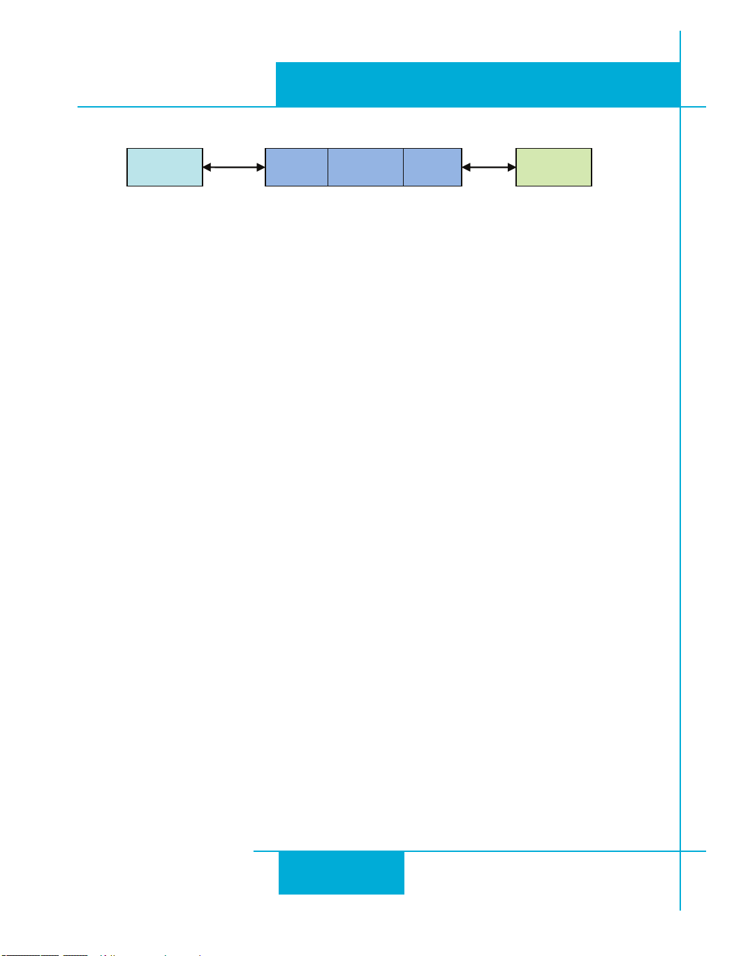
PC NIC1 NIC2 LAN DRIVE
Option 3: Use Two Network Interface Cards (NICs)
This technique allows you to keep your PC connected to your LAN, but keeps the drive off the LAN, prevent-
ing possible IP conicts or excessive trafc.
1. If you use a desktop PC and have a spare card slot, install a second NIC and connect it directly to the
drive using a CAT5 cable. You don’t need a special “crossover cable”; the drive will automatically
detect the direct connection and make the necessary physical layer changes.
2. If you use a laptop and only connect to your LAN using wireless networking, you can use the built-in
RJ45 Ethernet connection as your second NIC.
3. Set the IP address on the drive to “10.10.10.10” by setting the rotary switch at “0”.
4. To set the IP address of the second NIC:
a. On Windows XP, right click on “My Network Places” and select properties.
b. On Windows 7, click Computer. Scroll down the left pane until you see “Network”. Right click and
select properties. Select “Change adapter settings”
5. You should see an icon for your newly instated NIC. Right click again and select properties.
a. Scroll down until you see “Internet Properties (TCP/IP)”. Select this item and click the Properties
button.
b. On Windows 7 and Vista, look for “(TCP/IPv4)”
6. Select the option “Use the following IP address”. Then enter the address “10.10.10.11”. This will give
your PC an IP address that is on the same subnet as the drive. Windows will know to direct any traffic
intended for the drive’s IP address to this interface card.
7. Next, enter the subnet mask as “255.255.255.0”. Be sure to leave “Default gateway” blank. This will
prevent your PC from looking for a router on this subnet.
8. Because you are connected directly to the drive, anytime the drive is not powered on your PC will annoy
you with a small message bubble in the corner of your screen saying “The network cable is unplugged.”
16
Page 17
920-0004 Rev. C
+RX- +TX- GND +RX- +TX- GND +RX- +TX- GND
to PC TX+
to PC TX-
to PC RX+
to PC RX-
to PC GND
Drive #1 Drive #2 Drive #3
RX+
RX
–
TX
–
TX+
GND
RS-485/422
ST5/10-Si,-Q,-C, IP Hardware manual
4/21/11
Connecting to a host using RS-485 option card
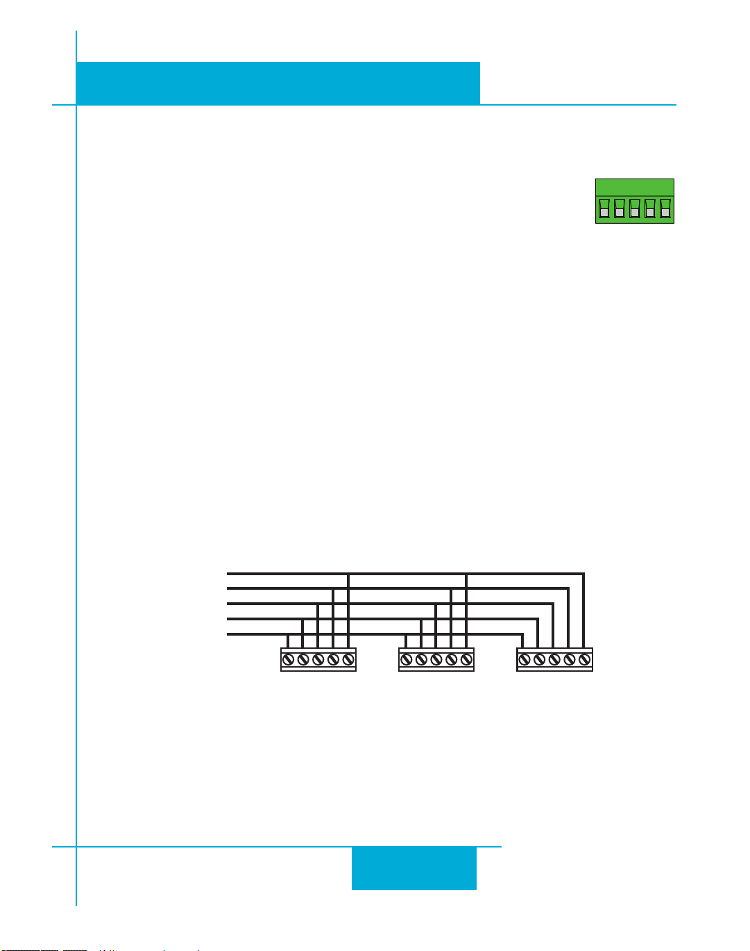
RS-485 allows you to connect more than one drive to a single host PC, PLC, HMI or other
computer. It also allows the communication cable to be long (more than 1000 feet). But
the device to which you connect must have an RS-485 port.
Pin diagram is shown to the right. Wiring diagrams can be found on the next page. We
recommend the use of Category 5 cable. It is widely used for computer networks, it is
inexpensive, easy to get and certified for quality and data integrity.
The ST drives can be used with either two wire or four wire RS-485 implementations. The connection can
be point to point (i.e. one drive and one host) or a multi-drop network (one host and up to 32 drives).
Four Wire Systems utilize separate transmit and receive wires. One pair of wires must connect the host
computer’s transmit signals to each drive’s RX+ and RX- terminals. Another pair connects the TX+ and TX-
drive terminals to the host computer’s receive signals. A logic ground terminal is provided on each drive
and can be used to keep all drives at the same ground potential. This terminal connects internally to the DC
power supply return (V-), so if all the drives on the RS-485 network are powered from the same supply it is
not necessary to connect the logic grounds. You should still connect one drive’s GND terminal to the host
computer ground.
Four wire systems are better than two wire types because the host can send and receive data at the same
time, increasing system throughput. Furthermore, the host never needs to disable its transmitter, which
simplifies your software.
RS-485 Four Wire System
17
Page 18
920-0004 Rev. C
+RX- +TX- GND +RX- +TX- GND +RX- +TX- GND
to PC TX+ (B)
to PC TX- (A)
to PC GND
Drive #1 Drive #2 Drive #3
4/21/11
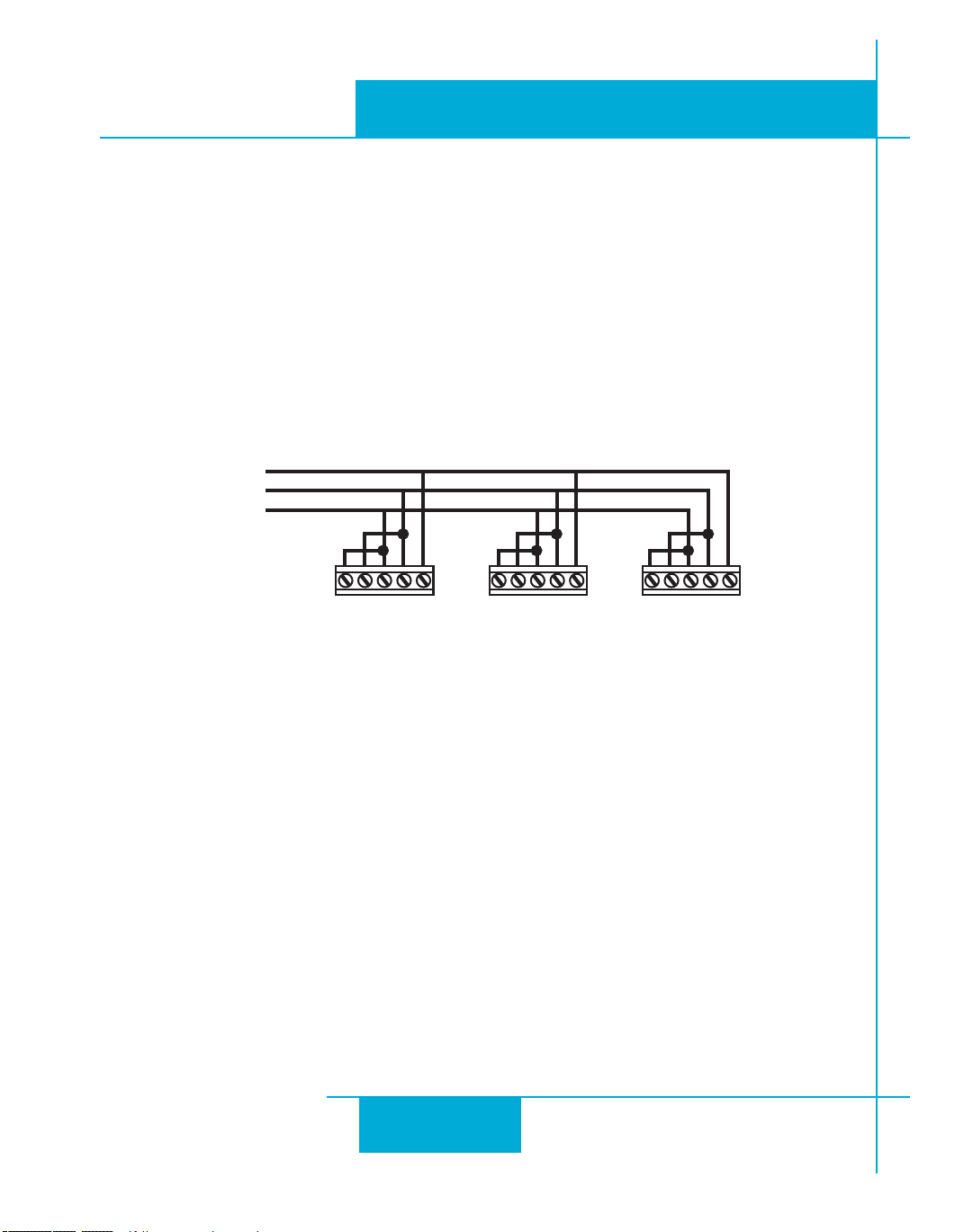
Two Wire Systems transmit and receive on the same pair of wires, which can lead to trouble. The host must
not only disable its transmitter before it can receive data, it must do so quickly, before a drive begins to
answer a query. The ST drives include a “transmit delay” parameter that can be adjusted to compensate for
a host that is slow to disable its transmitter. This adjustment can be made over the network using the TD
command, or it can be set using the ST Configurator software. It is not necessary to set the transmit delay
in a four wire system.
ST5/10-Si,-Q,-C, -IP Hardware manual
RS-232 to RS-485 2-wire Converter
Model 485-25E from Integrity Instruments (800-450-2001) works well for converting your PC’s RS-232 port
to RS-485. It comes with everything you need. Connect the adaptor’s “B” pin to the ST drive’s TX+ and RX+
terminals. Connect “A” to the drive’s TX- and RX- terminals.
RS-485 Two Wire System
Converting USB to RS-485
The USB-COMi-M from www.byterunner.com is an excellent choice for USB to RS-485 conversion. Set
SW1 to ON and SW2-4 to OFF. On the USB-COMi-M screw terminal connector: pin1 goes to RX- and TX-.
Connect pin 2 to RX+ and TX+. Pin 6 is ground. The DB-9 is not used.
Assigning Multi-Drop Addresses
Before wiring all of the drives in a multi-drop network, you’ll need to connect each drive individually to the
host computer so that a unique address can be assigned to each drive. Use the programming cable and the
ST Configurator™ software that came with your drive for this purpose.
Connect the drive to your PC, then launch the ST Configurator™ software. Finally, apply power to your
drive. If you have already configured your drive, then you should click the Upload button so that the ST
Configurator™ settings match those of your drive. Click on the Motion button, then select the “SCL”
operating mode. If you have a Q drive, you may want to select “Q Programming”. Either way, you’ll see the
18
Page 19

920-0004 Rev. C
ST5/10-Si,-Q,-C, IP Hardware manual
RS-485 Address panel appear. Just click on the address character of your choice. You can use the numerals 0..9 or the special characters ! “ # $ % & ‘ ( ) * + , - . / : ; < = > ? @ . Just make sure that each drive
on your network has a unique address. If you are using a 2 wire network, you may need to set the Transmit
Delay, too. 10 milliseconds works on the adapters we’ve tried. Once you’ve made your choices, click Download to save the settings to your drive.
4/21/11
Assigning CANopen Addresses
Each node on a CANopen system must have a unique Node ID. Valid ranges for the Node ID are 0x01
through 0x7F. Node ID 0x00 is reserved in accordance with DS301. The Node ID is selected using two rotary
switches; one sixteen position switch and one eight position switch. The sixteen position switch is located
just to the left of the CANopen connector. The eight position switch is located inside the drive, and may only
be accessed by removing the cover of the drive. It is recommended that the internal switch be left at the factory default setting “0”. However, if additional Node IDs are required, it is possible to access them using the
internal switch.
The Node ID is a concatenation of the two switch values. To set the Node ID to 0x3B, for example, turn the
internal eight position switch to the value “3”, and the sixteen position switch to the value “B”.
Please refer to the CANopen manual for more information.
19
Page 20

920-0004 Rev. C
4/21/11
ST5/10-Si,-Q,-C, -IP Hardware manual
Connecting the Power Supply
If you need information about choosing a power supply, please read Choosing a Power Supply located
elsewhere in this manual.
Connect the motor power supply “+” terminal to the driver terminal labeled “V+”. Connect power supply
“-” to the drive terminal labeled “V
connects to the power supply + terminal. This fuse is not user replaceable. If you want to install a user
servicable fuse in your system install a fast acting fuse in line with the + power supply lead. Use a 4 amp
fuse for the ST5 drives and 7 amps for the ST10.
The green ground screw on the corner of the chassis should be connected to earth ground.
Be careful not to reverse the wires. Reverse connection will destroy your driver, void your
warranty and generally wreck your day.
If you plan to use a regulated power supply you may encounter a problem with regeneration. If you rapidly
decelerate a load from a high speed, much of the kinetic energy of that load is transferred back to the power
supply. This can trip the overvoltage protection of a switching power supply, causing it to shut down. We
offer the RC050 “regeneration clamp” to solve this problem. If in doubt, buy an RC050 for your first instal-
lation. If the “regen” LED on the RC050 never ashes, you don’t need the clamp.
-
”. Use 18 or 20 gauge wire. The ST drives contain an internal fuse that
RC050 Regen Clamp
20
Page 21
ST5/10-Si,-Q,-C, IP Hardware manual
A+
A–
B+ B–
4
lead
motor
Red
Blue
Yellow
White
4 Leads
A+
A–
NC
B+
B–
NC
6
lead
motor
Red
Black
Red/
Wht
Green
Grn/Wht
White
A+
A–
NC
B+B–
NC
6
lead
motor
Grn/Wht
White
Green
Red
Red/
Wht
Black
6 Leads Series Connected 6 Leads Center Tap Connected
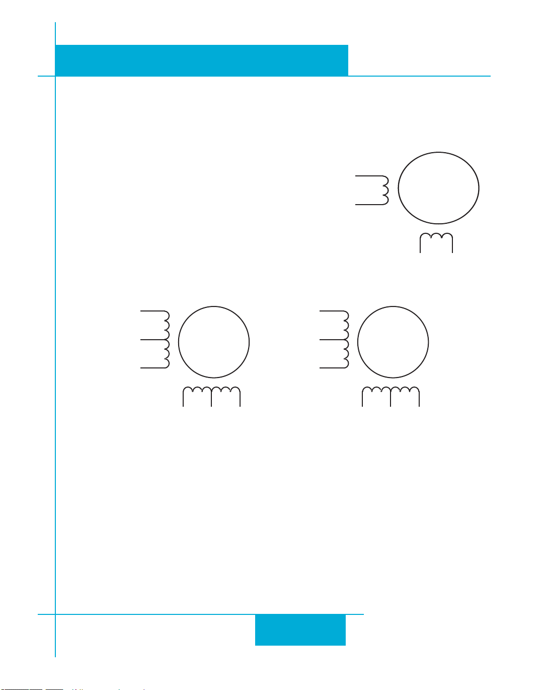
Connecting the Motor
Never connect or disconnect the motor while the power is on.
Four lead motors can only be connected one way. Please follow
the sketch at the right.
Six lead motors can be connected in series or center tap. In
series mode, motors produce more torque at low speeds, but
cannot run as fast as in the center tap configuration. In series operation, the motor should be operated at 30% less than the rated
current to prevent overheating. Winding diagrams for both connection methods are shown below. NC means not connected.
920-0004 Rev. C
4/21/11
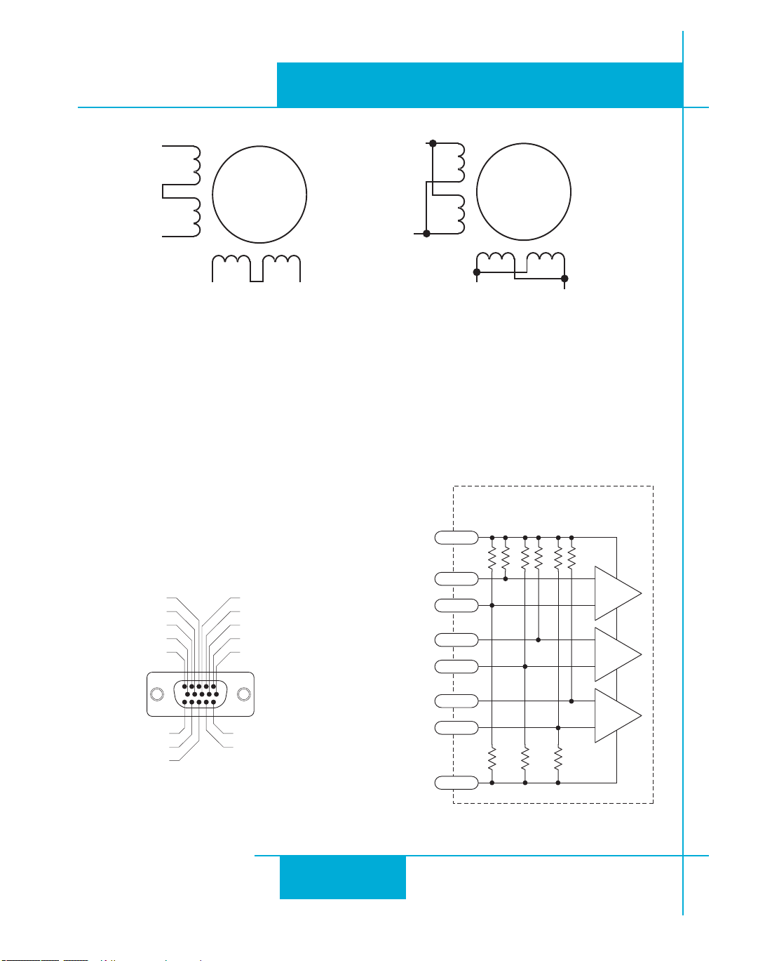
Eight lead motors can also be connected in two ways: series and parallel. As with six lead motors, series
operation gives you less torque at high speeds, but may result in lower motor losses and less heating. In
series operation, the motor should be operated at 30% less than the unipolar rated current. The motors
recommended in this manual should be connected in parallel. The wiring diagrams for eight lead motors are
shown on following page.
21
Page 22
920-0004 Rev. C
A+
A–
B+ B–
8
lead
motor
8 Leads Series Connected 8 Leads Parallel Connected
A+
A–
B+
B–
8
lead
motor
Orange
Org/Wht
Blk/Wht
Black
Red
Red/
Wht
Yel/
Wht
Yellow
Orange
Org/
Wht
Blk/Wht
Black
Red
Red/Wht
Yel/
Wht
Yel
low
encoder Z+ (5)
do not connect (10)
encoder B- (4)
do not connect (9)
encoder B+ (3)
do not connect (13)
do not connect (14)
shield (15)
(12) do not connect
(11) do not connect
(6) encoder Z-
(1) encoder A+
(7) +5VDC 200mA
(2) encoder A-
(8) GND
Front View
inside drive
A-
A+
2
GND
8
1
+5V
7
HD-15 Connector
B-
B+
4
3
Z-
Z+
6
5
5K
12.5K
8.3K
5K
12.5K
8.3K
5K
12.5K
8.3K
4/21/11
ST5/10-Si,-Q,-C, -IP Hardware manual
Connecting an Encoder (Requires the optional Encoder Feedback Card)
The encoder connections use a HD-15 connector, which you must connect to your encoder as shown below.
See back page for mating connector information.
If your encoder is single ended, connect the encoder outputs to the A+, B+ and Z+ inputs. Leave A-, B- and
Z- unconnected. (Z is the encoder index signal and is
optional.)
Pin Assignments (facing drive)
22
Internal Circuit
Page 23
920-0004 Rev. C
Front View
X COMMON
X3 / Enable
X5 / CWJOG
X4 / Alarm Reset
Analog IN2
Analog IN1
X2 / DIR-
X2 / DIR+
X1 / STEP +
X1 / STEP -
GND
GND
+5V OUT
Y COMMON
Y3 / FAULT
Y2 / MOTION
Y1 / BRAKE
��
��
��
��
��
��
��
��
��
�
�
�
�
�
�
�
�
�
��
��
��
��
��
��
��
X6 / CCWJOG
IN/OUT
X8/CCWLIMIT+
X8/CCWLIMIT-
X7/CWLIMIT-
X7/CWLIMIT+
Y4-
Y4+
ST5/10-Si,-Q,-C, IP Hardware manual
4/21/11
Connecting Input Signals
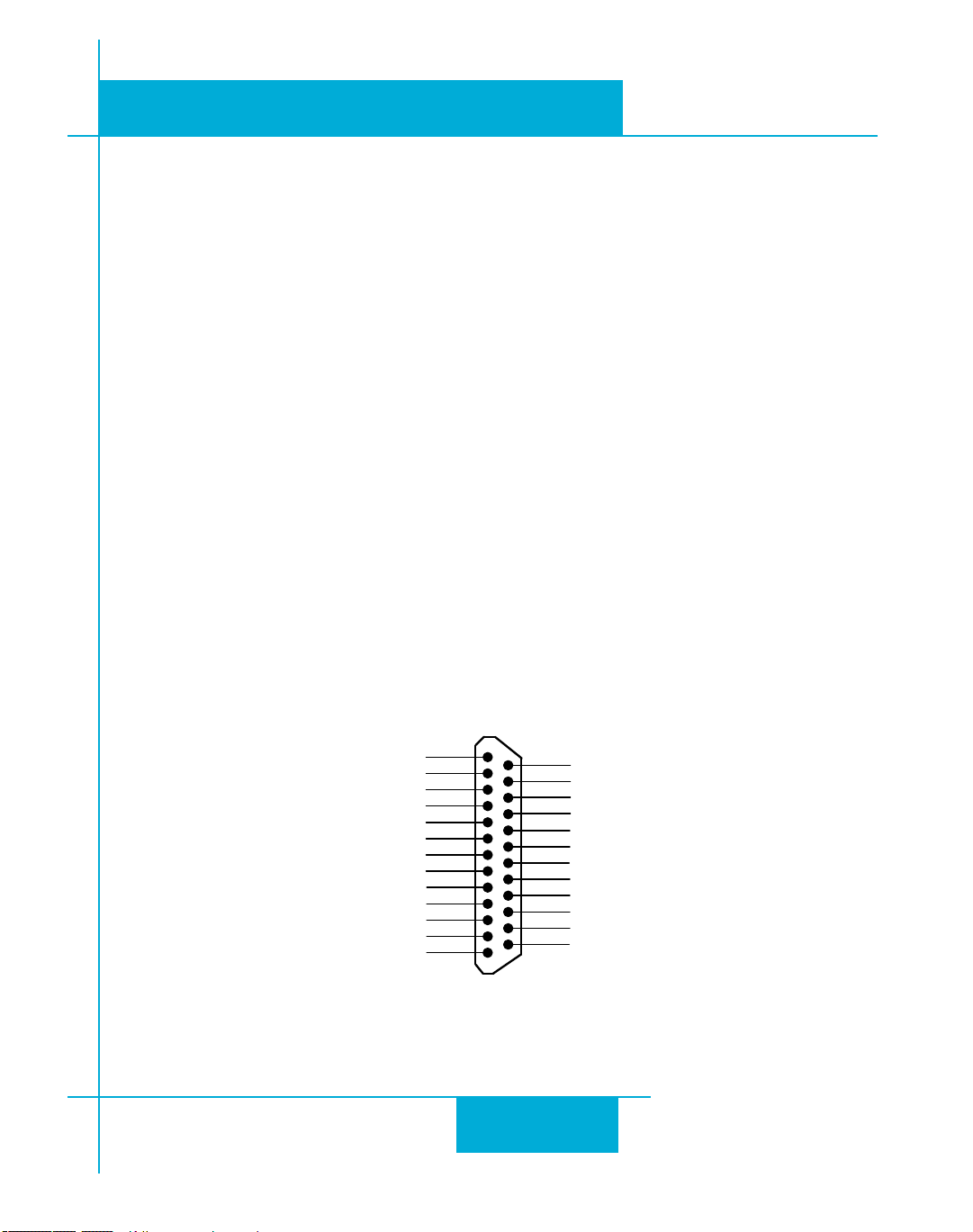
The ST drives have three types of inputs:
• high speed digital inputs for step & direction commands or encoder following, 5 volt logic
• digital inputs for other signals, 12 - 24 volt logic
• analog inputs for analog speed and positioning modes
All drives include eight digital inputs and two analog inputs.
• CW & CCW Limit: can be used to inhibit motion in a given direction, forcing the motor and load to travel
within mechanical limits. Can be configured for active closed, active open or not used.
• IN1/STEP & IN2/DIR: digital signals for commanding position. Quadrature signals from encoders can
also be used. These inputs can also be connected to sensors, switches and other devices for use with Q and
Si™ commands such as Wait Input, Seek Home, Feed to Sensor, If Input and others.
• IN3,4,5,6: software programmable inputs can be used for motor enable, alarm reset or jogging. These inputs can also be connected to sensors, switches and other devices for use with Q and Si™ Wait Input, Seek
Home, Feed to Sensor, If Input and other commands.
• Analog In: analog velocity or position command signal. Can be congured for 0-10V
with or without offset.
Connector Pin Diagram
, 0-5V, ±10V or ±5V,
IN/OUT1 (DB-25) Connector
23
Page 24
920-0004 Rev. C
IN/OUT 1
COM
X2/DIR-
DIR X2/DIR+
X1/STEP-
STEP X1/STEP+
Indexer
with
Sourcing
Outputs
IN/OUT 1
+5V OUT
X2/DIR+
DIR X2/DIR-
X1/STEP+
STEP X1/STEP-
Indexer
with
Sinking
Outputs
IN/OUT 1
DIR+
X2/DIR+
DIR- X2/DIR-
X1/STEP+
STEP-
STEP+
X1/STEP-
Indexer
with
Differential
Outputs
4/21/11
ST5/10-Si,-Q,-C, -IP Hardware manual
High Speed Digital Inputs
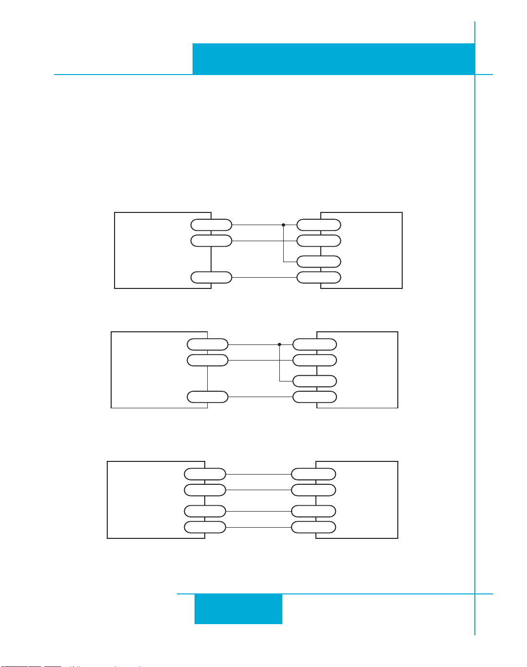
The ST Series drives include two high speed inputs called STEP and DIR. They accept 5 volt single-ended
or differential signals, up to 2 MHz. Normally these inputs connect to an external controller that provides
step & direction command signals. You can also connect a master encoder to the high speed inputs for following applications. Or you can use these inputs with Wait Input, If Input, Feed to Sensor, Seek Home and
other such commands.
Connection diagrams follow.
Connecting to indexer with Sourcing Outputs
Connecting to Indexer with Sinking Outputs
Connecting to Indexer with Differential Outputs
(Many High Speed Indexers have Differential Outputs)
24
Page 25
920-0004 Rev. C
DRIVE
+12-24V
GND
X2/DIR-
OUT1 X2/DIR+
X1/STEP-
OUT2 X1/STEP+
PLC
with
Sourcing
Outputs
R
R
-Si or -Q
drive
Master
Encoder
GND
X2/DIR-
X2/DIR+
X1/STEP-
X1/STEP+
GND
B-
B+
A-
A+
ST5/10-Si,-Q,-C, IP Hardware manual
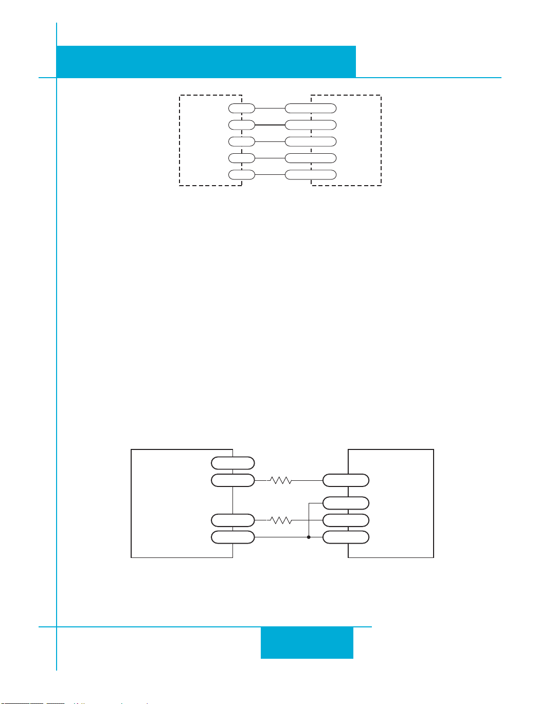
Wiring for Encoder Following
Using High Speed Inputs with 12-24 Volt Signals
Most PLCs don’t use 5 volt logic. You can connect signal levels as high as 24 volts to the STEP and DIR
inputs if you add external dropping resistors, as shown below.
• For 12 volt logic, add 820 ohm, 1/4 watt resistors
• For 24 volt logic, use 2200 ohm, 1/4 watt resistors
4/21/11
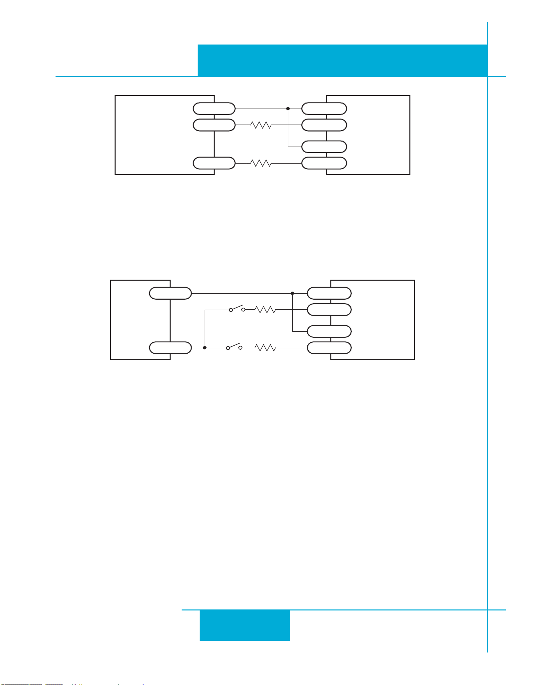
The maximum voltage that can be applied to an input terminal is 24 volts DC.
Never apply AC voltage to an input terminal.
Connecting to PLC with Sourcing (PNP) Outputs
(Most PLC’s use 24 volt logic)
25
Page 26
920-0004 Rev. C
DRIVE
+12-24V
X2/DIR+
DIR X2/DIR-
X1/STEP+
STEP X1/STEP-
PLC
with
Sinking
Outputs
R
R
DRIVE
+
X2/DIR+
X2/DIR-
X1/STEP+
- X1/STEP-
+24VDC
Power
Supply
2200
2200
direction switch
run/stop switch
(closed=run)
4/21/11
ST5/10-Si,-Q,-C, -IP Hardware manual
Connecting to PLC with Sinking (NPN) Outputs
(Most PLC’s use 24 volt logic)
Using Mechanical Switches at 24 Volts
26
Page 27
920-0004 Rev. C
2200
2200
2200
2200
2200
inside drive
XCOM
X3/EN
X4/RST
X5
X6
X8/CCWLIM-
8
7
6
5
4
25
X8/CCWLIM+
24
2200
X7/CWLIM-
23
X7/CWLIM+
22
DB-25 Connector
ST5/10-Si,-Q,-C, IP Hardware manual
4/21/11
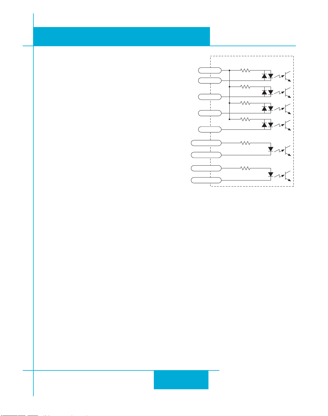
Other Digital Inputs
As we mentioned in the previous section, the high
speed STEP and DIR inputs are configured for five volt
logic. All other digital inputs are designed for operation
between 12 and 24 volts DC.
Single Ended Inputs
The ST drives include four single ended, optically isolated input circuits that can be used with
sourcing or sinking signals, 12 to 24 volts. This
allows connection to PLCs, sensors, relays and
mechanical switches. Because the input circuits
are isolated, they require a source of power. If you
are connecting to a PLC, you should be able to get
power from the PLC power supply. If you are using
relays or mechanical switches, you will need a 1224 V power supply. This also applies if you are connecting the inputs to the programmable outputs
of an Si product from Applied Motion.
What is COM?
“Common” is an electronics term for an electrical connection to a common voltage. Sometimes
“common” means the same thing as “ground”, but not always. In the case of the ST drives, if you
are using sourcing (PNP) input signals, then you will want to connect COM to ground (power sup-
ply -). If you are using sinking (NPN) signals, then COM must connect to power supply +.
Note: If current is flowing into or out of an input, the logic state of that input is low or closed. If no
current is flowing, or the input is not connected, the logic state is high or open.
The diagrams on the following pages show how to connect the inputs to various commonly used
devices.
27
Page 28
920-0004 Rev. C
IN/OUT1
X3..X6
XCOM
DRIVE
OUT+
OUT–
12-24
VDC
Power
Supply
-
+
DRIVE
NPN
Proximity
Sensor
X3..X6
XCOM
output
+
–
12-24
VDC
Power
Supply
-
+
DRIVE
switch or relay
(closed=logic low)
X3..X6
XCOM
12-24
VDC
Power
Supply
-
+
4/21/11
ST5/10-Si,-Q,-C, -IP Hardware manual
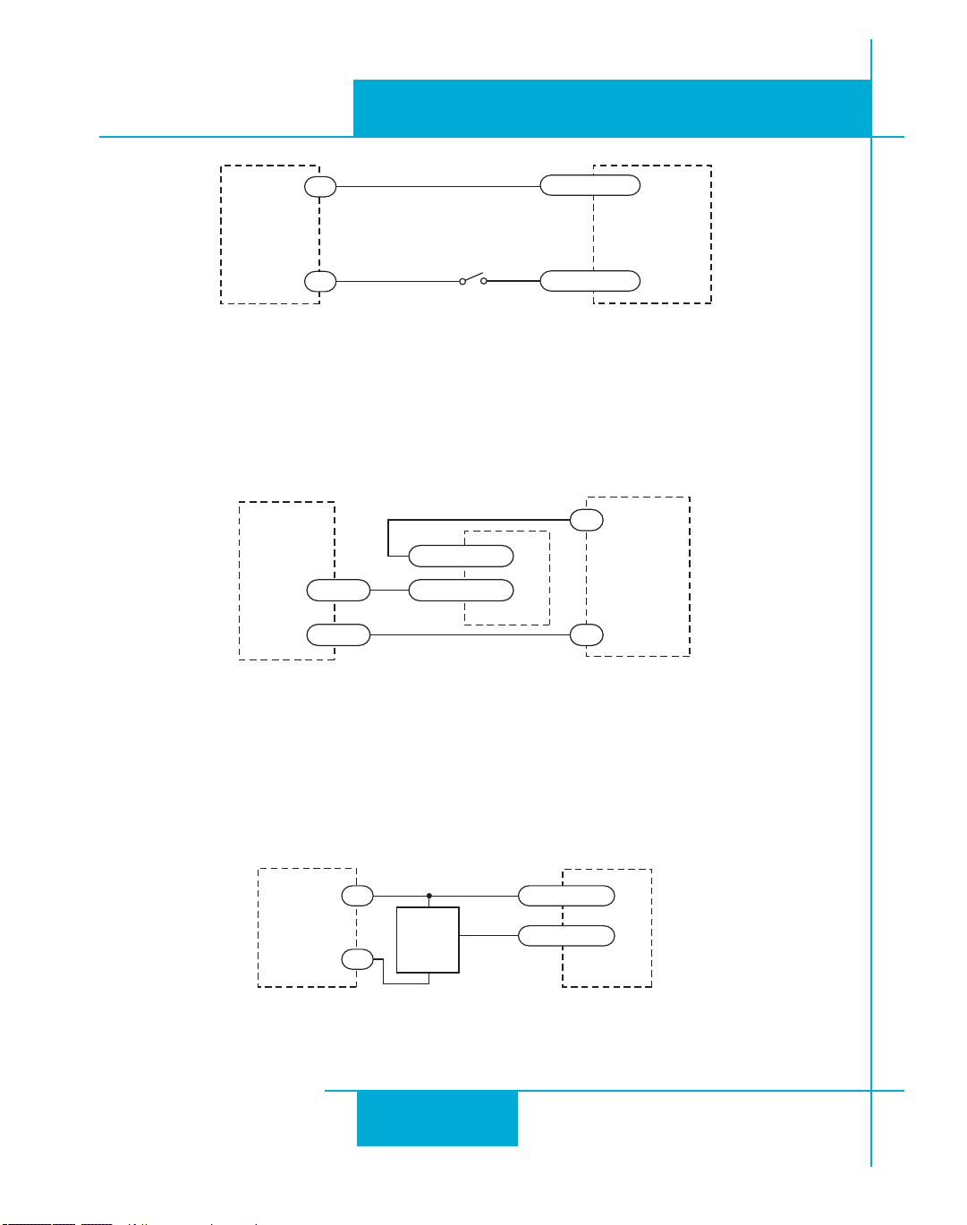
Connecting an Input to a Switch or Relay
Connecting another Si™ drive to the ST
(When output closes, input goes low).
Connecting an NPN Type Proximity Sensor to an input
(When prox sensor activates, input goes low).
28
Page 29
920-0004 Rev. C
DRIVE
PNP
Proximity
Sensor
X3..X6
output
+
–
XCOM
12-24
VDC
Power
Supply
-
+
inside drive
2200
X8/CCWLIM-
25
X8/CCWLIM+
24
2200
X7/CWLIM-
23
X7/CWLIM+
22
ST5/10-Si,-Q,-C, IP Hardware manual
4/21/11
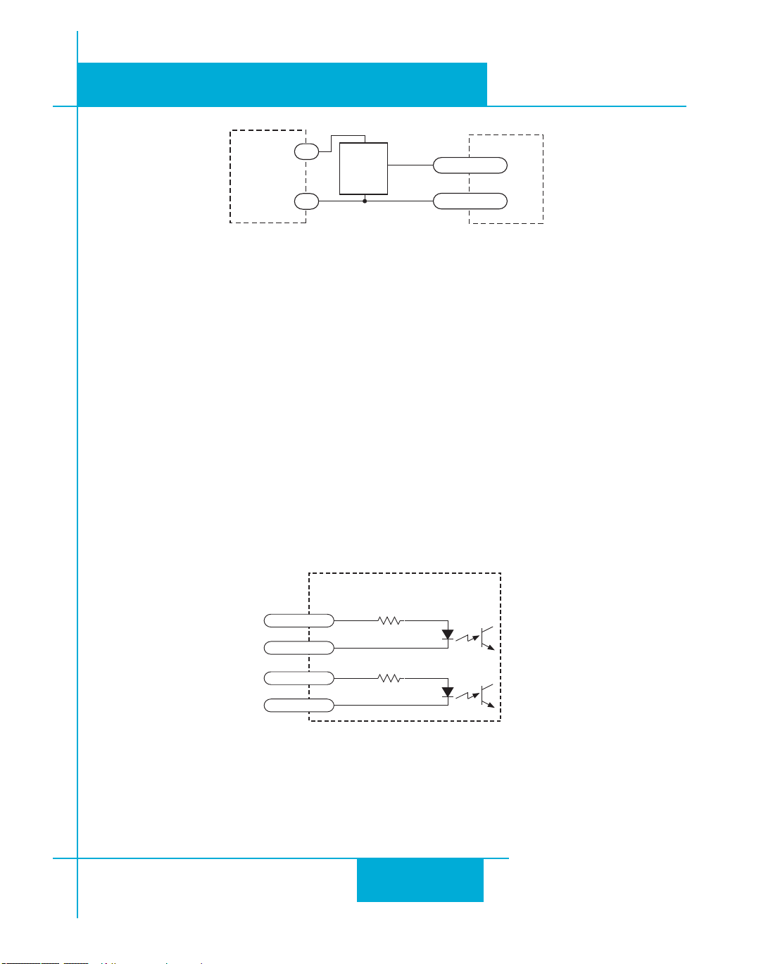
Connecting a PNP Type Proximity Sensor to a an input
(When prox sensor activates, input goes low).
Connecting Limit Switches
The CWLIMIT and CCWLIMIT inputs are used for connecting end of travel sensors. These inputs
are differential, which allows you to use signals that are sinking (NPN), sourcing (PNP) or differential (line driver). By connecting switches or sensors that are triggered by the motion of the motor
or load, you can force the motor to operate within certain limits. This is useful if a program or
operator error could cause damage to your system by traveling too far.
The limit inputs are optically isolated. This allows you to choose a voltage for your limit circuits of
12 to 24 volts DC. This also allows you to have long wires on limit sensors that may be far from
the drive with less risk of introducing noise to the drive electronics. The schematic diagram of the
limit switch input circuit is shown below.
29
Page 30
920-0004 Rev. C
DRIVE
+
DC
Power
Supply
–
Limit
Sensor
output
+
–
CW LIMIT+
CW LIMIT-
DRIVE
+
DC
Power
Supply
–
Proximity
Sensor
output
+
–
CW LIMIT+
CW LIMIT-
DRIVE
+
12-24
VDC
SUPPLY
-
CW LIMIT+
CW LIMIT-
CCW LIMIT+
CCW LIMIT-
4/21/11
ST5/10-Si,-Q,-C, -IP Hardware manual
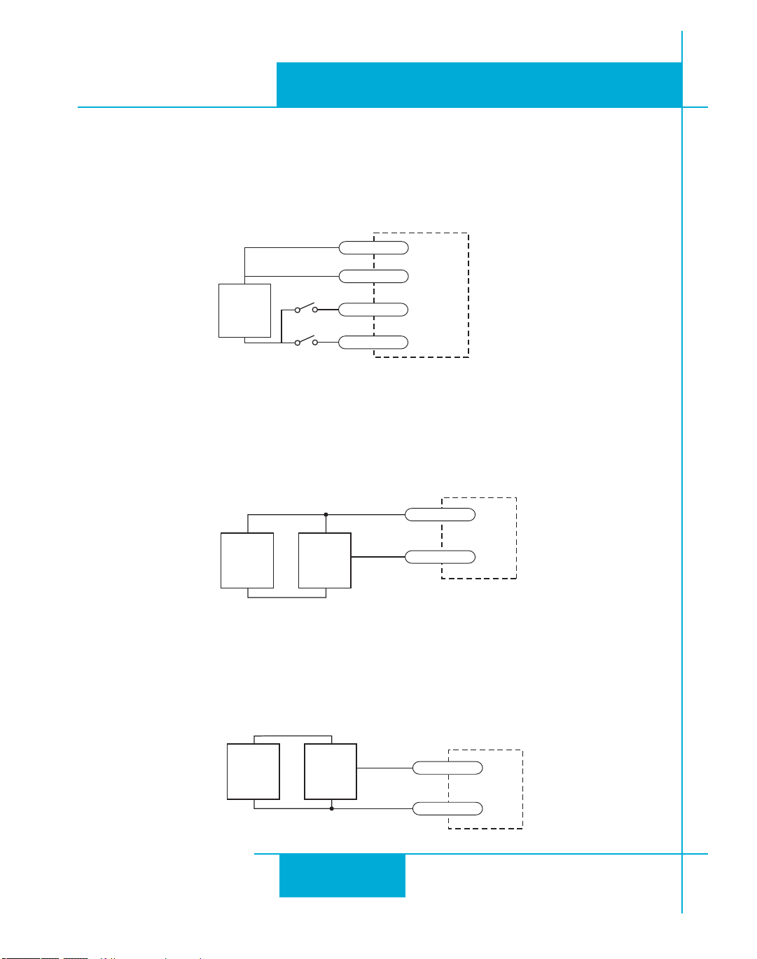
Wiring a Mechanical Limit Switch
You can use normally open or normally closed limit switches. Either way, wire them as shown
here. Be sure to set the polarity using the Si Programmer™ for Si™ drives or the ST Configurator™
software for the ST5-Q, ST10-Q, ST5-C and ST10-C.
Wiring a Limit Sensor
Some systems use active limit sensors that produce a voltage output rather than a switch or relay
closure. These devices must be wired differently than switches.
If your sensor has an open collector output or a sinking output, wire it like this:
If the sensor output goes low at the limit, select the option “closed” (in the software). If the output
is open, or high voltage, choose “open”.
Other sensors have sourcing outputs. That means that current can ow out of the sensor output,
but not into it. In that case, wire the sensor this way:
30
Page 31
ST5/10-Si,-Q,-C, IP Hardware manual
inside drive
AIN1
AIN2
GND
1
2
13
DB-25 Connector
Signal
Conditioning
Signal
Conditioning
1-10kW
pot
cw
ccw
DRIVE
GND
AIN
+5V OUT
18
1
13
AIN2
2
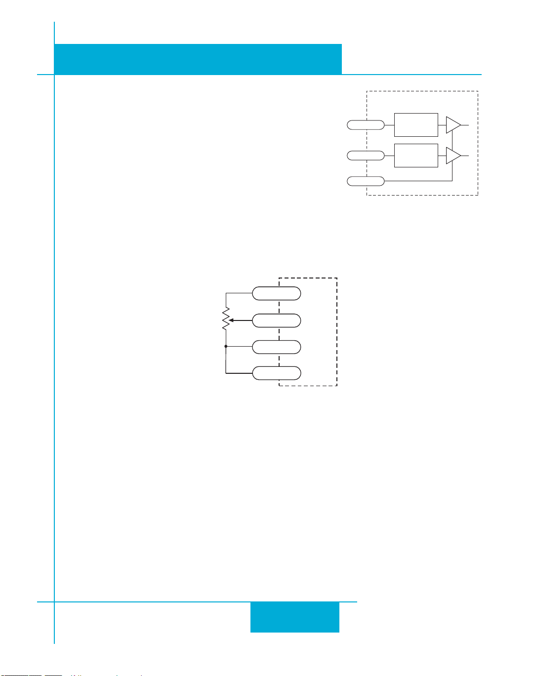
Analog Inputs
The ST drives feature two analog inputs. Each input can accept
a signal range of 0 to 5 VDC, ±5 VDC, 0 to 10 VDC or ±10 VDC.
The drive can be configured to operate at a speed or position
that is proportional to the analog signal.
A shielded cable is recommended for electrically noisy
environments.
Use the ST Configurator software to set the signal range, offset,
deadband and filter frequency.
920-0004 Rev. C
4/21/11
Connecting a Potentiometer to Analog Input 1
31
Page 32
920-0004 Rev. C
IN/OUT1
YCOM
Y1/2/3
5-24 VDC
Power Supply
+ –
Load
IN/OUT1
Y1
YCOM
Y3
Y2
14
17
15
16
Y4+
Y4-
20
21
IN/OUT1
Y4-
Y4+
5-24 VDC
Power Supply
+ –
Load
4/21/11
ST5/10-Si,-Q,-C, -IP Hardware manual
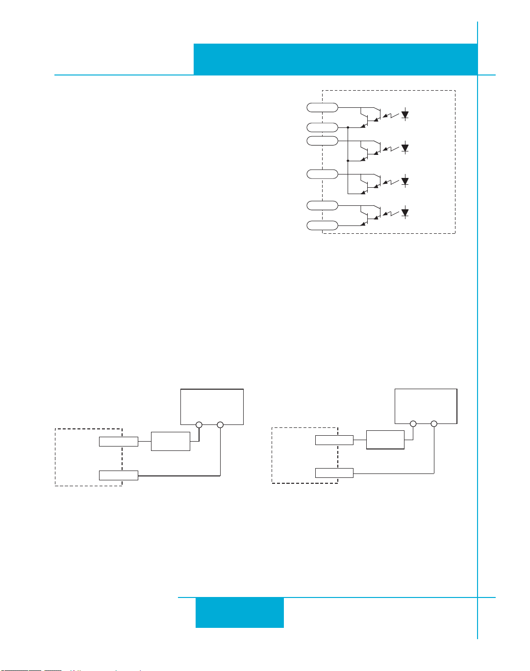
Programmable Outputs
The ST drives feature four digital outputs. These outputs can
be set to automically control a motor brake, to signal a fault
condition, to indicate when the motor is moving or to provide
an output frequency proportional to motor speed (tach signal).
Or the outputs can be turned on and off by program instructions
like Set Output.
The outputs can be used to drive LEDs, relays and the inputs
of other electronic devices like PLCs and counters. For Y4, the
“+” (collector) and “-” (emitter) terminals of each transistor are
available at the connector. This allows you to configure this
output for current sourcing or sinking. The Y1-3 outputs can
only sink current. The Y COM terminal must be tied to power supply (-).
Diagrams of each type of connection follow.
Do not connect the outputs to more than 30VDC.
The current through each output terminal must not exceed 100 mA.
Sinking Output
Using Y1, Y2, Y3
Sinking Output
Using Y4
32
Page 33
ST5/10-Si,-Q,-C, IP Hardware manual
IN/OUT1
YCOM
Y1/2/3
1N4935 suppression diode
5-24 VDC
Power Supply
+ –
relay
PLC
IN/OUT1
5-24 VDC
Power Supply
+ –
YCOM
Y1/2/3
IN
COM
PLC
IN/OUT1
5-24 VDC
Power Supply
+ –
Y4-
Y4+
IN
COM
IN/OUT1
Y4-
Y4+
1N4935 suppression diode
5-24 VDC
Power Supply
+ –
relay
920-0004 Rev. C
4/21/11
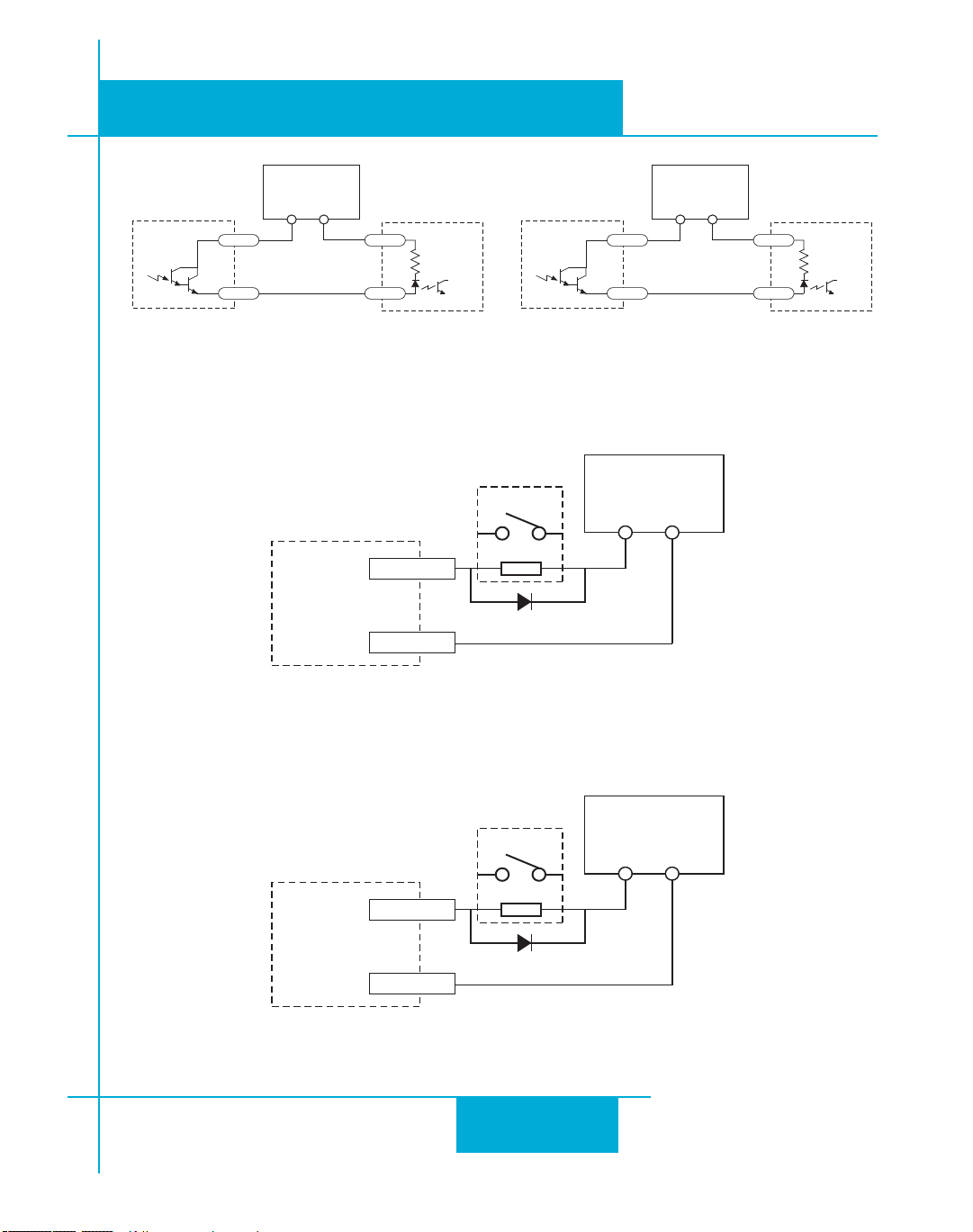
Sourcing Output
Y1, Y2 or Y3
Driving a Relay
Y1, Y2 or Y3
Sourcing Output
Using Y4
Driving a Relay
Using Y4
33
Page 34

920-0004 Rev. C
4/21/11
ST5/10-Si,-Q,-C, -IP Hardware manual
Choosing a Power Supply
When choosing a power supply, there are many things to consider. If you are manufacturing equipment that
will be sold to others, you probably want a supply with all the safety agency approvals. If size and weight
are an issue use a switching supply.
You must also decide what size of power supply (in terms of voltage and current) is needed for your application.
Voltage
PWM drives work by switching the voltage to the motor terminals on and off while monitoring current to
achieve a precise level of phase current. To do this efficiently and silently, you’ll want to have a power
supply with a voltage rating at least five times that of the motor. Depending on how fast you want to run the
motor, you may need even more voltage than that.
If you choose an unregulated power supply, make sure the no load voltage of the supply does not exceed the
drive’s maximum input voltage specification.
Current
The maximum supply current you could ever need is the sum of the two phase currents. However, you will
generally need a lot less than that, depending on the motor type, voltage, speed and load conditions. That’s
because the ST drives use switching amplifiers, converting a high voltage and low current into lower voltage
and higher current. The more the power supply voltage exceeds the motor voltage, the less current you’ll
need from the power supply. A motor running from a 48 volt supply can be expected to draw only half the
supply current that it would with a 24 volt supply.
We recommend the following selection procedure:
1. If you plan to use only a few drives, get a power supply with at least twice the rated phase current of
the motor.
2. If you are designing for mass production and must minimize cost, get one power supply with more
than twice the rated current of the motor. Install the motor in the application and monitor the current
coming out of the power supply and into the drive at various motor loads. This will tell you how much
current you really need so you can design in a lower cost power supply.
34
Page 35
920-0004 Rev. C
0 5 10 15 20 25 30 35 40
0
5
10
15
20
25
HT11-012, 1.2A
5014-842, 1.2A
HT11-013, 1.2A
Torque (oz-in)
Speed (rev/sec)
24 Volts DC
ST5/10-Si,-Q,-C, IP Hardware manual
Recommended Motors
Holding Drive Rotor
Part Torque Current Setting Resistance Inductance Inertia
Number oz-in kg-cm amps ohms mH g-cm2
HT��-��� �.� �.�� �.� �.� �.� �
HT��-��� ��.� �.�� �.� �.� �.� ��
����-��� ��.� �.�� �.� �.� �.� ��
HT��-��� ��.� �.�� �.� �.� �.� ��
HT��-��� ��.� �.�� �.� �.� �.� ��
HT��-��� ��.� �.�� �.� �.� �.� ��
HT��-��� ��.� �.�� �.� �.� �.� ���
HT��-��� ��� ��.� �.� �.� �.� ���
HT��-��� ��� ��.� �.� �.� �.� ���
HT��-��� ��� ��.� ��.� �.�� �.� ����
HT��-��� ���� ��.� �.� �.�� �.� ����
HT��-��� ���� ��� ��.� �.�� �.� ����
Note: The “Drive Current Setting” shown here differs from the rated current of each motor because the rated
current is RMS and the drive current setting is peak sine. If you are using a motor not listed here, for best
results set the drive current at the motor’s rated current x 1.2.
4/21/11
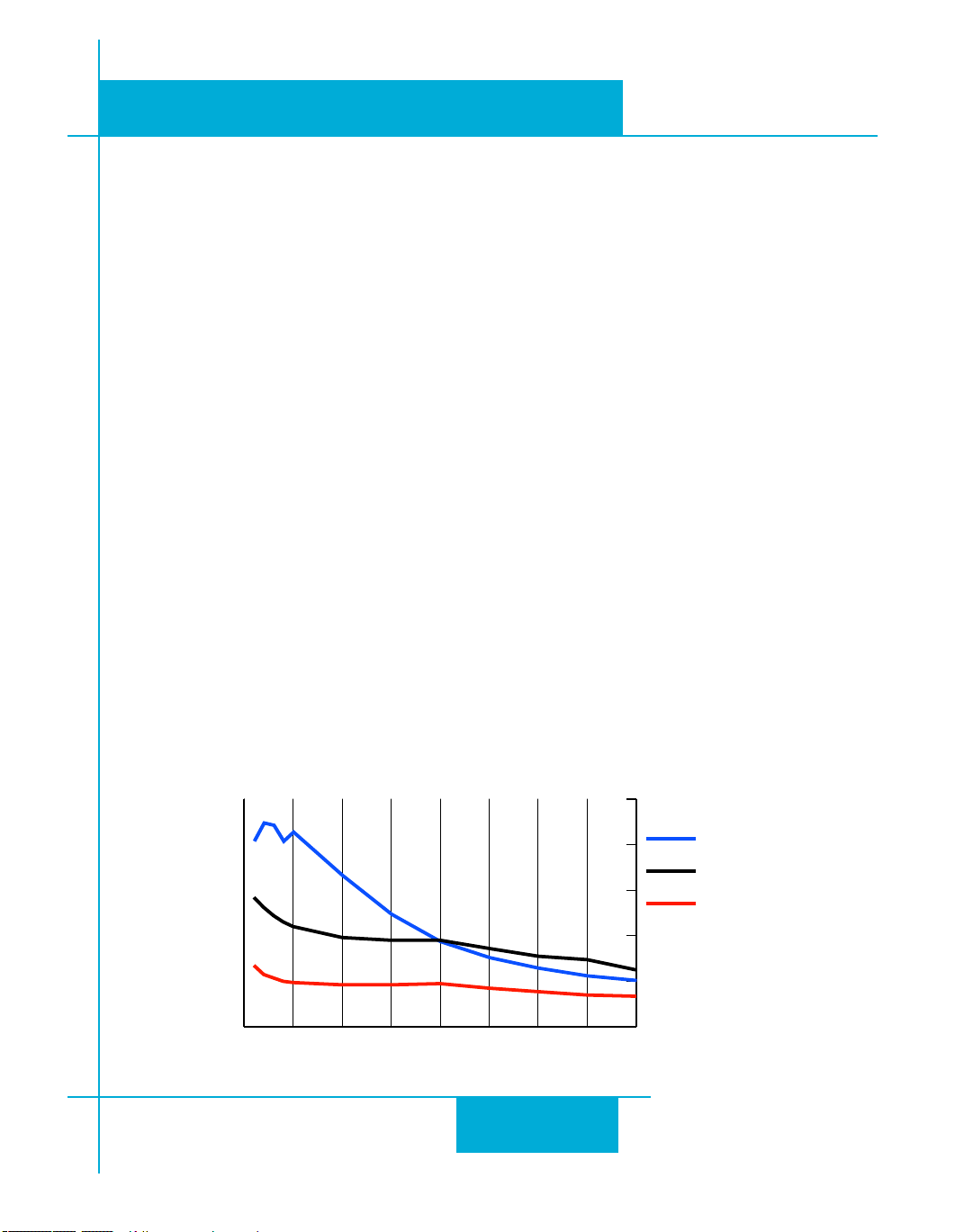
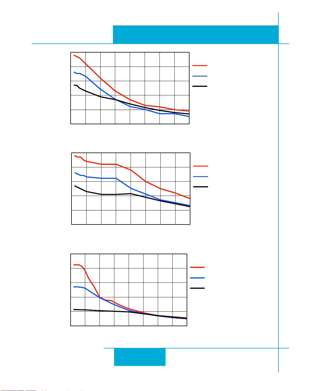
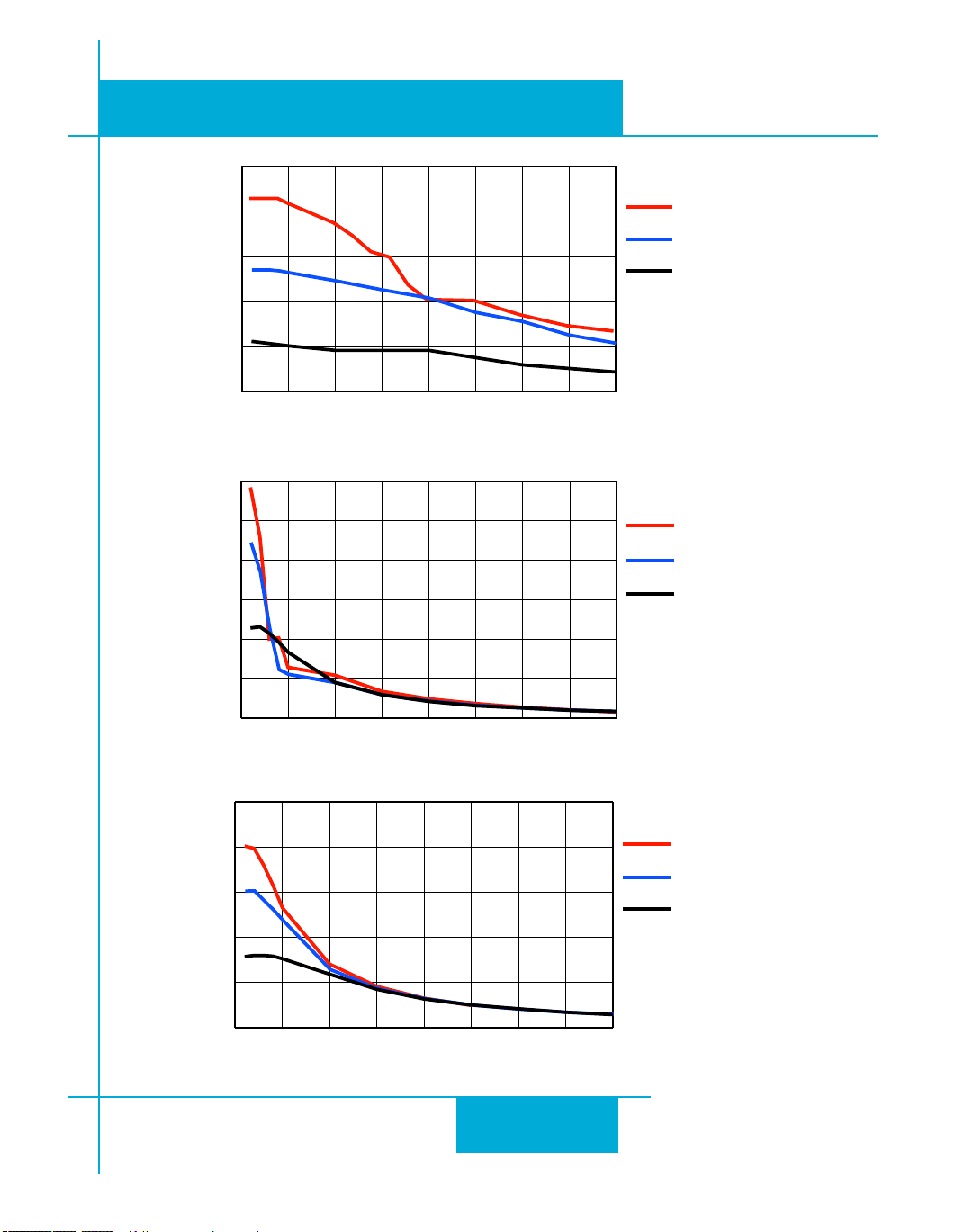
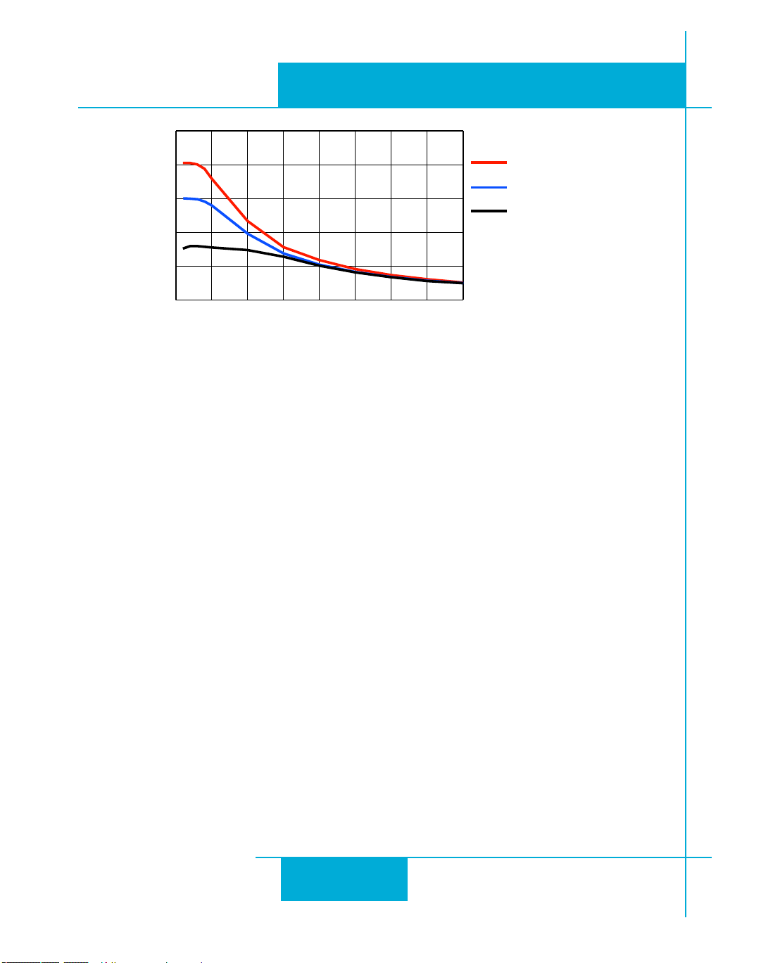
Torque-Speed Curves
Note: all torque curves were measured at 20,000 steps/rev.
35
Page 36
920-0004 Rev. C
0 5 10 15 20 25 30 35 40
0
50
100
150
200
250
HT23-401, 5A
HT23-398, 5A
HT23-394, 3.4A
Torque (oz-in)
Speed (rev/sec)
24 Volts DC
0 5 10 15 20 25 30 35 40
0
10
20
30
40
50
HT17-075, 2A
HT17-071, 2A
HT17-068, 1.6A
Torque (oz-in)
Speed (rev/sec)
24 Volts DC
0 5 10 15 20 25 30 35 40
0
10
20
30
40
50
HT17-075, 2A
HT17-071, 2A
HT17-068, 1.6A
Torque (oz-in)
Speed (rev/sec)
48 Volts DC
4/21/11
ST5/10-Si,-Q,-C, -IP Hardware manual
36
Page 37
ST5/10-Si,-Q,-C, IP Hardware manual
0 5 10 15 20 25 30 35 40
0
200
400
600
800
1000
1200
HT34-487, 10A
HT34-486, 9.7A
HT34-485, 10A
Torque (oz-in)
Speed (rev/sec)
with ST10 Drive
24 Volts DC
0 5 10 15 20 25 30 35 40
0
300
600
900
1200
1500
HT34-487, 10A
HT34-486, 9.7V
HT34-485, 10A
Torque (oz-in)
Speed (rev/sec)
with ST10 Drive
48 Volts DC
0 5 10 15 20 25 30 35 40
0
50
100
150
200
250
HT23-401, 5A
HT23-398, 5A
HT23-394, 3.4A
Torque (oz-in)
Speed (rev/sec)
48 Volts DC
920-0004 Rev. C
4/21/11
37
Page 38
920-0004 Rev. C
0 5 10 15 20 25 30 35 40
0
300
600
900
1200
1500
HT34-487, 10A
HT34-486, 9.7A
HT34-485, 10A
Torque (oz-in)
Speed (rev/sec)
with ST10 Drive
80 Volts DC
4/21/11
ST5/10-Si,-Q,-C, -IP Hardware manual
Motor Heating
Step motors convert electrical power from the driver into mechanical power to move a load. Because step
motors are not perfectly efficient, some of the electrical power turns into heat on its way through the motor.
This heating is not so much dependent on the load being driven but rather the motor speed and power supply voltage. There are certain combinations of speed and voltage at which a motor cannot be continuously
operated without damage.
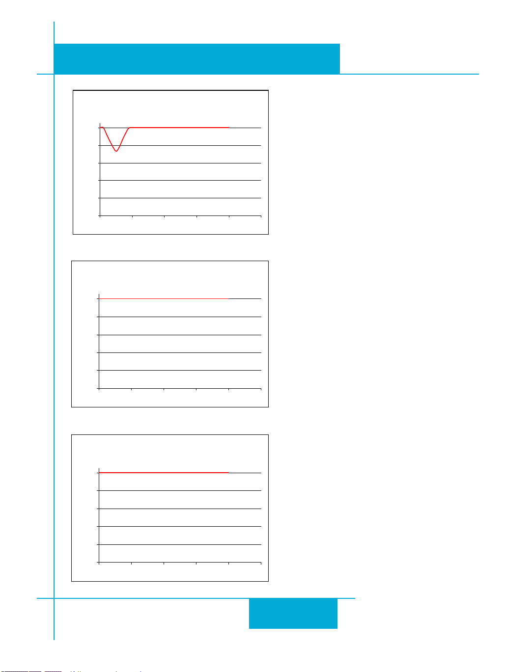
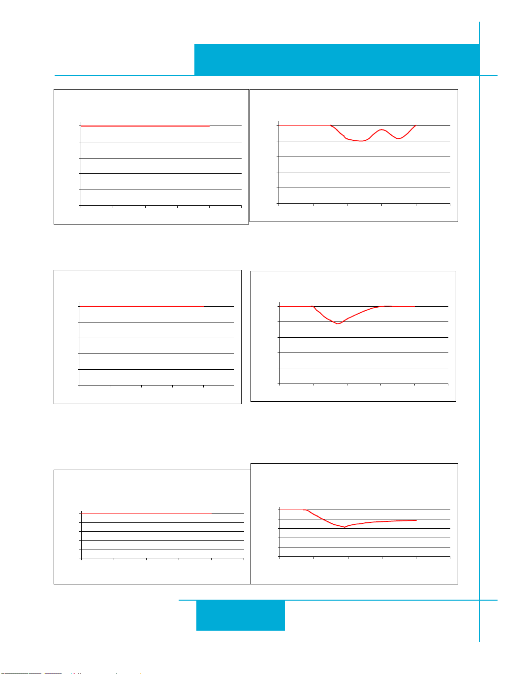
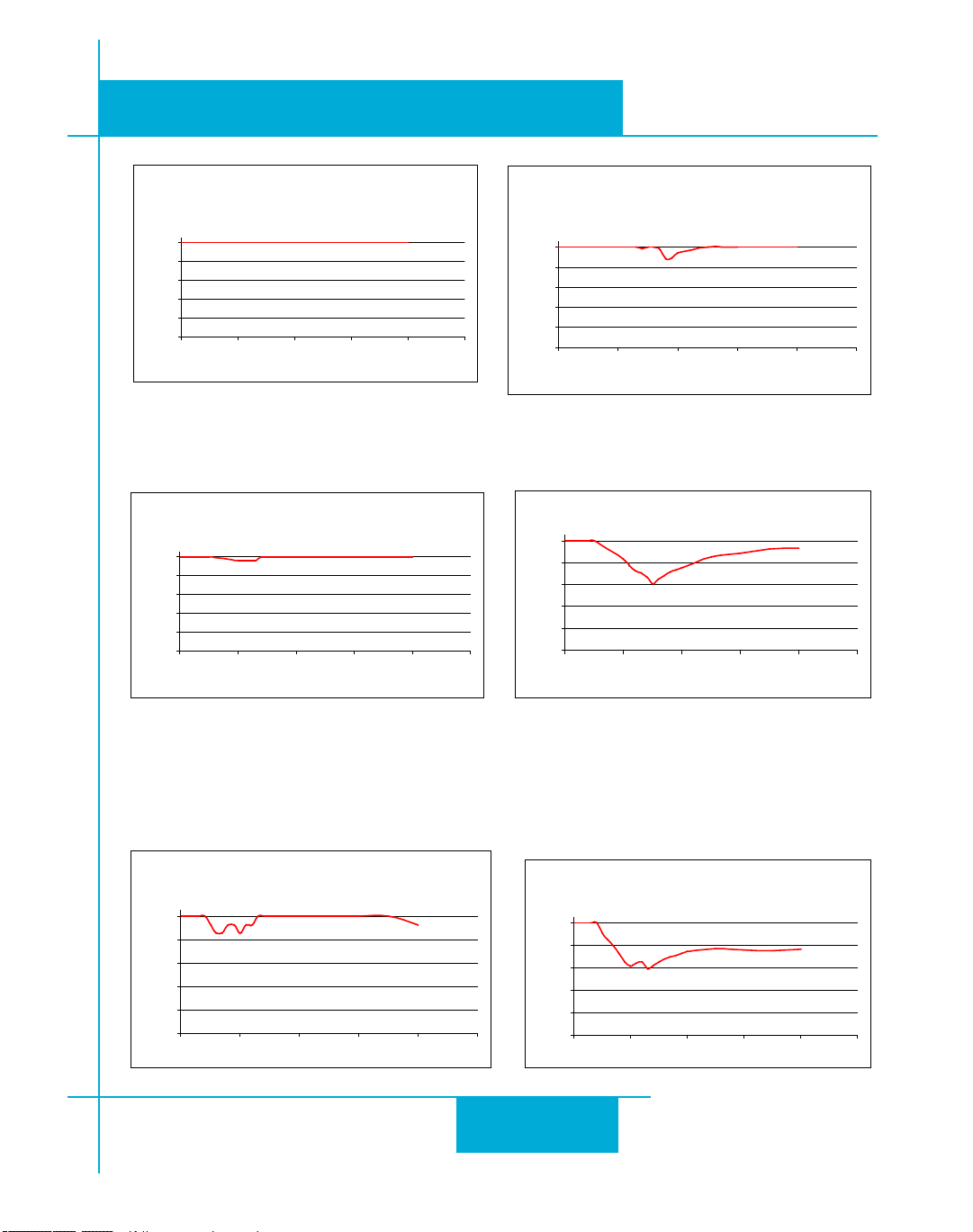
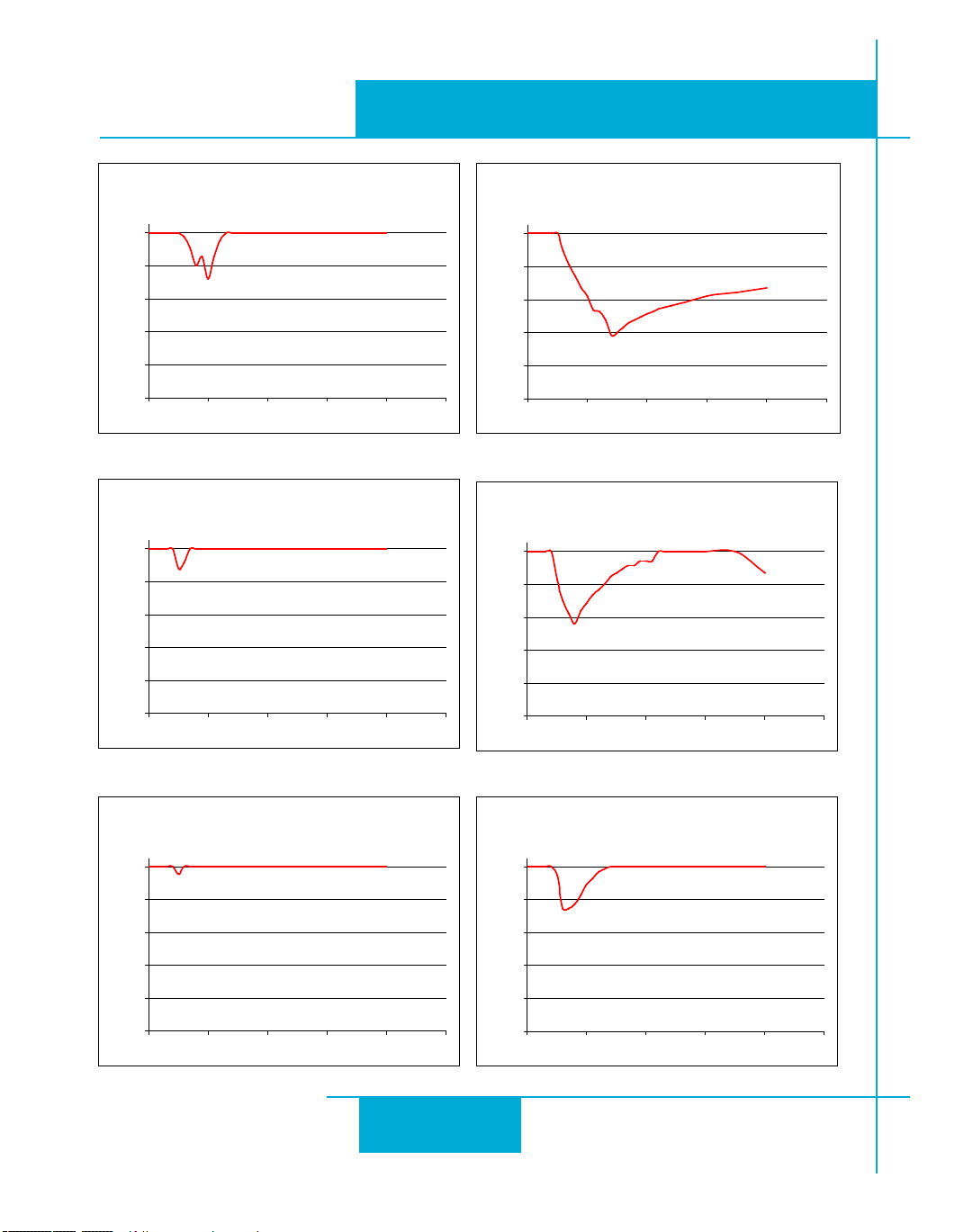
We have characterized the recommended motors in our lab and provided curves showing the maximum duty
cycle versus speed for each motor at commonly used power supply voltages. Please refer to these curves
when planning your application.
Please also keep in mind that a step motor typically reaches maximum temperature after 30 to 45 minutes
of operation. If you run the motor for one minute then let it sit idle for one minute, that is a 50% duty cycle.
Five minutes on and five minutes off is also 50% duty. However, one hour on and one hour off has the effect
of 100% duty because during the first hour the motor will reach full (and possibly excessive) temperature.
The actual temperature of the motor depends on how much heat is conducted, convected or radiated out of
it. Our measurements were made in a 40°C (104°F) environment with the motor mounted to an aluminum
plate sized to provide a surface area consistent with the motor power dissipation. Your results may vary.
38
Page 39
ST5/10-Si,-Q,-C, IP Hardware manual
5014-842 Max Duty Cycle vs Speed
24 VDC, 1.2A, 40°C Ambient
Mounted on 4.75" x 4.75" x .25" Aluminum Plate
0
20
40
60
80
100
0 10 20 30 40 50
Speed (RPS)
% Duty Cycle
HT11-012 Max Duty Cycle vs Speed
24 VDC, 1.2A, 40°C Ambient
Mounted on 3.5" dia x .125" Aluminum Plate
0
20
40
60
80
100
0 10 20 30 40 50
Speed (RPS)
% Duty Cycle
HT11-013 Max Duty Cycle vs Speed
24 VDC, 1.2A, 40°C Ambient
Mounted on 3.5" dia x .125" Aluminum Plate
0
20
40
60
80
100
0 10 20 30 40 50
Speed (RPS)
% Duty Cycle
920-0004 Rev. C
4/21/11
39
Page 40
920-0004 Rev. C
HT17-068 Max Duty cycle vs Speed
24 VDC, 1.60 Amps @40°C Ambient
on 4.75 x 4.75 x .25 Aluminum Plate
0
20
40
60
80
100
0 10 20 30 40 50
Speed (RPS)
% Duty Cycle
HT17-071 Max Duty Cycle vs Speed
24 VDC, 2.0 Amps 40°C Ambient
on 4.75 x 4.75 x .25 Aluminum Plate
0
20
40
60
80
100
0 10 20 30 40 50
Speed (RPS)
% Duty Cycle
HT17-075 Max Duty Cycle vs Speed
24 VDC, 2.0 Amps 40°C Ambient
on 4.75 x 4.75 x .25 Aluminum Plate
0
20
40
60
80
100
0 10 20 30 40 50
Speed (RPS)
% Duty Cycle
HT17-068 Max Duty cycle vs Speed
48 VDC, 1.60 Amps 40
°C Ambient
on 4.75 x 4.75 x .25 Aluminum Plate
0
20
40
60
80
100
0 10 20 30 40 50
Speed (RPS)
% Duty Cycle
HT17-071 Max Duty cycle vs Speed
48 VDC, 2.0 Amps 40
°C Ambient
on 4.75 x 4.75 x .25 Aluminum Plate
0
20
40
60
80
100
0 10 20 30 40 50
Speed (RPS)
% Duty Cycle
HT17-075 Max Duty cycle vs Speed
48 VDC, 2.0 Amps 40
°C Ambient
on 4.75 x 4.75 x .25 Aluminum Plate
0
20
40
60
80
100
0 10 20 30 40 50
Speed (RPS)
% Duty Cycle
4/21/11
ST5/10-Si,-Q,-C, -IP Hardware manual
40
Page 41
ST5/10-Si,-Q,-C, IP Hardware manual
HT23-394 Max Duty Cycle vs Speed
48 VDC, 3.4 Amps, 40°C Ambient
on 6.4 x 6.4 x .25 Aluminum Plate
0
20
40
60
80
100
0 10 20 30 40 50
Speed (RPS)
% Duty Cycle
HT23-398 Max Duty cycle vs Speed
0
20
40
60
80
100
0 10 20 30 40 50
Speed (RPS)
% Duty Cycle
48VDC, 5.0A, 40°C Ambient
on 6.4 x 6.4 x .25 Aluminum Plate
HT23-401 Max Duty cycle vs Speed
48 VDC, 5.0 Amps 40
°C Ambient
on 6.4 x 6.4 x .25 Aluminum Plate
0
20
40
60
80
100
0 10 20 30 40 50
Speed (RPS)
% Duty Cycle
HT23-394 Max Duty Cycle vs Speed
24 VDC, 3.4 Amps, 40°C Ambient
on 6.4 x 6.4 x .25 Aluminum Plate
0
20
40
60
80
100
0 10 20 30 40 50
Speed (RPS)
% Duty Cycle
HT23-398 Max Duty cycle vs Speed
24VDC, 5.0A, 40°C Ambient
on 6.4 x 6.4 x .25 Aluminum Plate
0
20
40
60
80
100
0 10 20 30 40 50
Speed (RPS)
% Duty Cycle
HT23-401 Max Duty Cycle vs Speed
24 VDC, 5.0 Amps, 40°C Ambient
on 6.4 x 6.4 x .25 Aluminum Plate
0
20
40
60
80
100
0 10 20 30 40 50
Speed (RPS)
% Duty Cycle
920-0004 Rev. C
4/21/11
41
Page 42
920-0004 Rev. C
HT34-487 Max Duty Cycle vs Speed
48 VDC, 10.0 Amps 40°C Ambient
on 10 x 10 x .5 Aluminum Plate
0
20
40
60
80
100
0 10 20 30 40 50
Speed (RPS)
% Duty Cycle
HT34-486 Max Duty cycle vs Speed
80 VDC, 10.0 Amps 40
°C Ambient
on 10 x 10 x .5 Aluminum Plate
0
20
40
60
80
100
0 10 20 30 40 50
Speed (RPS)
% Duty Cycle
HT34-486 Max Duty Cycle vs Speed
48 VDC, 10.0 Amps 40°C Ambient
on 10 x 10 x .5 Aluminum Plate
0
20
40
60
80
100
0 10 20 30 40 50
Speed (RPS)
% Duty Cycle
HT34-485 Max Duty cycle vs Speed
48 VDC, 10.0 Amps 40°C Ambient
on 10 x 10 x .5 Aluminum Plate
0
20
40
60
80
100
0 10 20 30 40 50
Speed (RPS)
% Duty Cycle
HT34-487 Max Duty cycle vs Speed
80 VDC, 10.0 Amps 40
°C Ambient
on 10 x 10 x .5 Aluminum Plate
0
20
40
60
80
100
0 10 20 30 40 50
Speed (RPS)
% Duty Cycle
HT34-485 Max Duty cycle vs Speed
80 VDC, 10.0 Amps 40
°C Ambient
on 10 x 10 x .5 Aluminum Plate
0
20
40
60
80
100
0 10 20 30 40 50
Speed (RPS)
% Duty Cycle
4/21/11
ST5/10-Si,-Q,-C, -IP Hardware manual
42
Page 43
920-0004 Rev. C
3.0
1.775
5.0
6X SLOT 0.16
WIDE, FULL R
0.663
1.98
0.61
4.74
ST5/10-Si,-Q,-C, IP Hardware manual
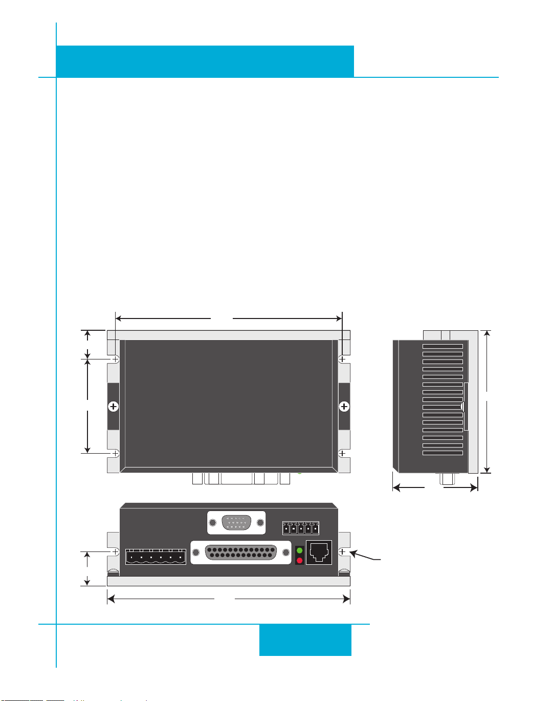
Mounting the Drive
You can mount your drive on the wide or the narrow side of the chassis using #6 screws. If possible, the
drive should be securely fastened to a smooth, at metal surface that will help conduct heat away from the
chassis. If this is not possible, then forced airow from a fan may be required to prevent the drive from
overheating.
• Never use your drive in a space where there is no air flow or where other devices cause
the surrounding air to be more than 40°C.
• Never put the drive where it can get wet or where metal or other electrically conductive
particles can get on the circuitry.
• Always provide air flow around the drive. When mouting multiple ST drives near each
other, maintain at least one half inch of space between drives.
Mechanical Outline
4/21/11
43
Page 44

920-0004 Rev. C
4/21/11
ST5/10-Si,-Q,-C, -IP Hardware manual
Technical Specifications
Amplifier
Digital MOSFET. 20 kHz PWM.
ST5: 18 - 53 VDC, motor current: 0.5 to 5.0 amps/phase peak of sine
ST10: 18 - 88 VDC, motor current: 0.5 to 10 amps/phase peak of sine
Digital Inputs
Step & Direction: differential, optically isolated, 5V logic. 330 ohms internal resistance.
0.5 µsec minimum pulse width. 2 µsec minimum set up time for direction signal.
All other digital inputs: optically isolated, 12 - 24V logic. 2200 ohms. Maximum current: 10 mA.
Analog Inputs
±10VDC, 12 bit ADC, 100k ohms internal impedance.
Outputs
Photodarlington, 100 mA, 30 VDC max. Voltage drop: 1.2V max at 100 mA.
Physical
1.775 x 3 x 5 inches overall. 10 oz (280 g)
Ambient temperature range: 0°C to 40°C.
44
Page 45

920-0004 Rev. C
ST5/10-Si,-Q,-C, IP Hardware manual
Mating Connectors and Accessories
Mating Connectors
Motor/power supply: PCD P/N ELV06100, included with drive.
IN/OUT1: DB-25 male. AMP P/N 5-747912-2. Shell Kit AMP P/N 5-748678-3. Included.
Optional encoder feedback: HD-15 male. Norcomp P/N 180-015-102-001. Shell Kit AMP P/N 5-748678-
1. Not included.
Accessories
Breakout Box for DB-25 Connector
BOB-1, includes cable
Screw Terminal Connectors that mate directly to the DB-25 connector on the front panel of the drive:
Phoenix Contact P/N 2761622
This connector is not available from Applied Motion. You must purchase it from a
Phoenix distributor.
Mating Cable for IN/OUT connector with “ying leads”
Black Box P/N: BC00702
This cable is not available from Applied Motion. You must purchase it from Black Box.
Useful for custom wired applications. This shielded cable has a DB-25 connector on each
end. You can cut off the female end to create a 6 foot “DB-25 to ying lead cable”.
It’ll be easier to wire if you get the cable color chart from Black Box’s web site.
4/21/11
Regeneration Clamp:
Applied Motion Products RC050.
Power supplies:
Applied Motion Products PS320A48 (48 VDC, 6.7A)
Applied Motion Products PS150A24 (24 VDC, 6.3A)
Applied Motion Products PS50A24 (24 VDC, 2.1A)
Operator Terminal (-Si drives only)
Applied Motion Products MMI-01 or MMI-02 (backlit).
Recommended CANopen USB Adapter (-C drives only)
Kvaser LeafLight HS This adapter is not available from Applied Motion Products
45
Page 46
Alarm Codes
Front View
X COMMON
X3 / Enable
X5 / CWJOG
X4 / Alarm Reset
Analog IN2
Analog IN1
X2 / DIR-
X2 / DIR+
X1 / STEP +
X1 / STEP -
GND
GND
+5V OUT
Y COMMON
Y3 / FAULT
Y2 / MOTION
Y1 / BRAKE
��
��
��
��
��
��
��
��
��
�
�
�
�
�
�
�
�
�
��
��
��
��
��
��
��
X6 / CCWJOG
IN/OUT
X8/CCWLIMIT+
X8/CCWLIMIT-
X7/CWLIMIT-
X7/CWLIMIT+
Y4-
Y4+
RX+
RX
–
TX
–
TX+
GND
RS-485/422
encoder Z+ (5)
do not connect (10)
encoder B- (4)
do not connect (9)
encoder B+ (3)
do not connect (13)
do not connect (14)
shield (15)
(12) do not connect
(11) do not connect
(6) encoder Z-
(1) encoder A+
(7) +5VDC 200mA
(2) encoder A-
(8) GND
Front View
Code Error
solid green no alarm, motor disabled
flashing green no alarm, motor enabled
1 red, 1 green motor stall (optional encoder only)
1 red, 2 green move attempted while drive disabled
1 red, 3 green subroutine stack overflow (Si only)
2 red, 1 green ccw limit
2 red, 2 green cw limit
2 red, 3 green subroutine stack underflow (Si only)
3 red, 1 green drive overheating
3 red, 2 green internal voltage out of range
3 red, 3 green blank Q segment
4 red, 1 green power supply overvoltage
4 red, 2 green power supply undervoltage
4 red, 3 green bad instruction in Si program
5 red, 1 green over current / short circuit
5 red, 2 green motor resistance out of range
6 red, 1 green open motor winding
6 red, 2 green bad encoder signal (optional encoder only)
7 red, 1 green serial communication error
7 red, 2 green flash memory error
8 red, 1 green internal voltage out of range
GND
CAN_L
SHLD
CAN_H
Re-Order from
omegamation.com
Omegamation
TM
1-888-55-OMEGA
1-888-55-66342
1-888-55-66342
Re-Order from
omegamation.com
Omegamation
TM
1-888-55-OMEGA
1-888-55-66342
1-888-55-66342
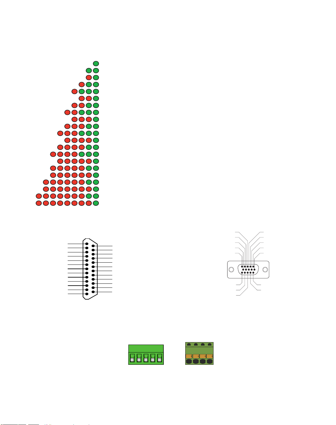
In the event of an error, the red and green LEDs on the main board will ash in alternating red-green patterns as shown below.
The pattern repeats until the alarm is cleared.
Connector Diagrams
DB-25 I/O Connector
HD-15 Encoder Connector
CANopen
Applied Motion Products, Inc.
Tel (831) 761-6555 (800) 525-1609 Fax (831) 761-6544
404 Westridge Drive Watsonville, CA 95076
www.appliedmotionproducts.com
 Loading...