

Page 1
TM
User’s Guide
Shop online at
omega.com
e-mail: [email protected]
For latest product manuals:
www.omegamanual.info
SP-001, SP-002
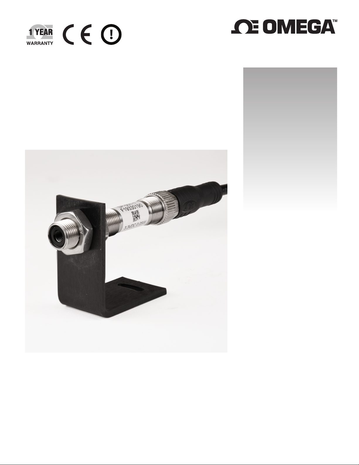
Ultra Miniature IR Smart Probe
Page 2

omega.com [email protected]
Servicing North America:
U.S.A. Omega Engineering, Inc.
Headquarters: 800 Connecticut Ave. Suite 5N01, Norwalk, CT 06854
Toll-Free: 1-800-826-6342 (USA & Canada only)
Customer Service: 1-800-622-2378 (USA & Canada only)
Engineering Service: 1-800-872-9436 (USA & Canada only)
Tel: (203) 359-1660 Fax: (203) 359-7700
e-mail: [email protected]
The information contained in this document is believed to be correct, but OMEGA accepts no liability for any errors it contains, and
reserves the right to alter specifications without notice.
Page 3

Table of Contents
Notes Warnings, and Cautions ....................................................................................... 4
Introduction ................................................................................................................... 5
Description ................................................................................................................ 5
Included with Your SP-001 / SP-002 .......................................................................... 5
Additional Material Needed ...................................................................................... 5
Optional Materials .................................................................................................... 5
Manuals / Software ................................................................................................... 5
Input / Output Pin Layout .............................................................................................. 6
Optical Chart .................................................................................................................. 6
Preparation .................................................................................................................... 7
Positioning ................................................................................................................ 7
Distance and Spot Size .............................................................................................. 7
Ambient Temperature .............................................................................................. 7
Atmospheric Quality ................................................................................................. 7
Electrical Interference ............................................................................................... 7
Mechanical Installation .................................................................................................. 8
Software Setup .............................................................................................................. 8
Connecting to Omega Sync – Automatic Detect........................................................ 8
Connecting to Omega Sync – Manual ....................................................................... 8
Communication Interface ......................................................................................... 9
Setting Emissivity ..........................................................................................................10
Known Emissivity Value .......................................................................................... 10
Setting Emissivity via Emissivity Table ..................................................................... 10
Setting Emissivity via Secondary Temperature Device ............................................ 10
Adjusting Spike and Noise Suppression .........................................................................11
Alarm Setting ................................................................................................................11
Appendix A - Emissivity Table .......................................................................................11
Specifications ................................................................................................................11
Safety and Regulatory Compliance ...............................................................................11
3 | Page
Page 4

Notes Warnings, and Cautions
If the equipment is used in a manner not specified in this manual, the protection provided by the equipment may be
impaired.
Do not operate the equipment in flammable or explosive environments.
It is important to read and follow all the precautions and instructions in this manual before operating or commissioning this
device as it contains important information relating to safety and EMC. Failure to follow all the safety precautions may
result in injury and / or damage to your equipment.
The following labels identify information that is especially important to note:
Note: Provides you with information that is important to successfully setup and use the SP-001.
Caution or Warning: Tells you about the risk of electrical shock.
Caution, Warning, or Important: Tells you of circumstances that can affect the instruments functionality and must
refer to accompanying documents.
Tip: Provides you helpful hints.
4 | Page
Page 5
Introduction
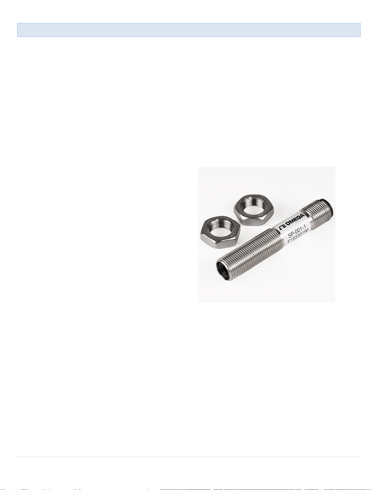
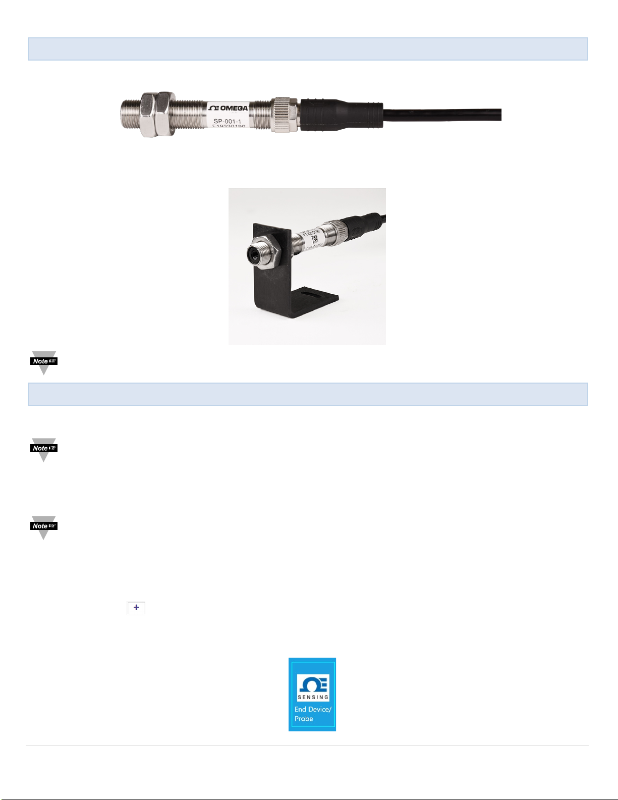
Figure 1
Description
The Omega Smart IR Temperature Probe is a miniature infrared sensor that measures the surface temperature of a solid or
liquid without contact. It can measure non-metal surfaces between -70 to 380°C (-94 to 716°F). It also features a built-in
sensor to measure the ambient temperature of the probe itself.
Materials including paper, thick plastics, rubber, food and organic materials, as well as painted metals and most dirty, rusty
or oily surfaces, are measured accurately, safely and cleanly.
The Smart Probe is packaged into a rugged 12 mm OD x 67 mm long compact, stainless steel, IP67 (NEMA 6) housing designed for heavy industrial use while taking up the least amount of space for easy installation. Standard features include:
easy configuration through free Sync configuration software, adjustable emissivity and filtering, and a wide operating
temperature range of -40°C to 85°C.
We’ve integrated an advanced suite of IIoT centric featured electronics called Smart Core. These features enable plug and
play connectivity, fully featured alarms and notifications, data assurance, and data storage of up to 1499 sensor readings.
Included with Your SP-001 / SP-002
• SP-001 / SP-002
• Quick Start Guide
• Two Mounting Nuts
Additional Material Needed
• Smart Interface (IF-001-0) or Wireless Transmitter
• Computer / Laptop with Windows OS
• Omega Sync software
(Downloadable on the Omega Website)
Optional Materials
• Secondary temperature measurement device.
(RTD, Thermocouple, etc.)
Manuals / Software
The latest User Manual, Quick Start Guide, and Omega Sync
software are available to download on the Omega website.
5 | Page
Page 6
Function
Description
OUT 1
Output enabled models
INTR
Smart Sensor INTR signal
SCL 1
Smart sensor SCL signal
SDA 1
Smart Sensor SDA signal
SHIELD
Connected to metal housing
OUT 2
Output enabled models
GND
Power return
VCC
3.3 Vdc
Optical Chart
Input / Output Pin Layout
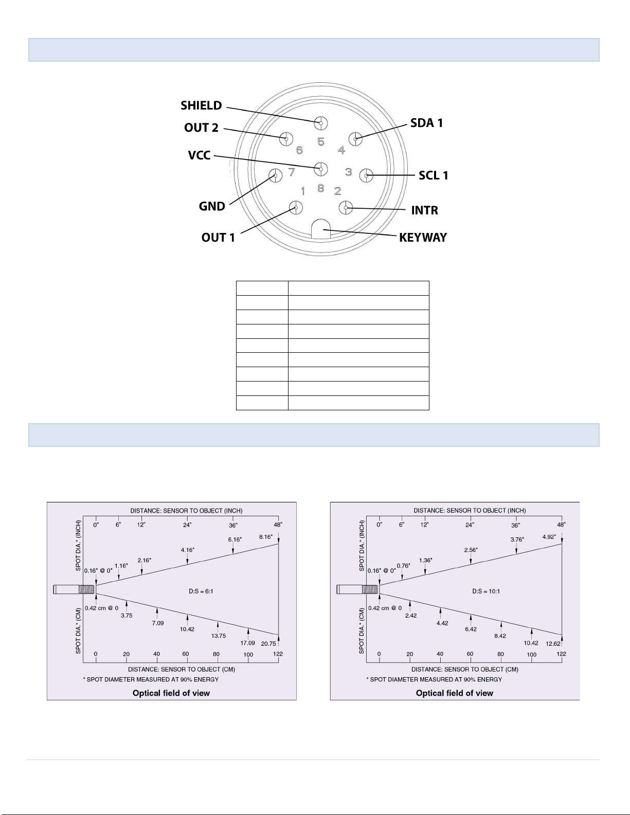
The following pin layout depicts a rearview of the SP-001 / SP-002.
Figure 2
The optical chart below indicates the nominal target spot diameter at any given distance from the sensing head and
assumes 90% energy. Figure 3 reflects the SP-001 with a field of view of 6:1. Figure 4 reflects the SP-002 with a field of view
of 10:1.
Figure 3 Figure 4
6 | Page
Page 7
Preparation
The installation Process consists of the following stages:
• Preparation
• Mechanical Installation
• Software Setup
Please read the following sections thoroughly before proceeding with the installation.
Positioning
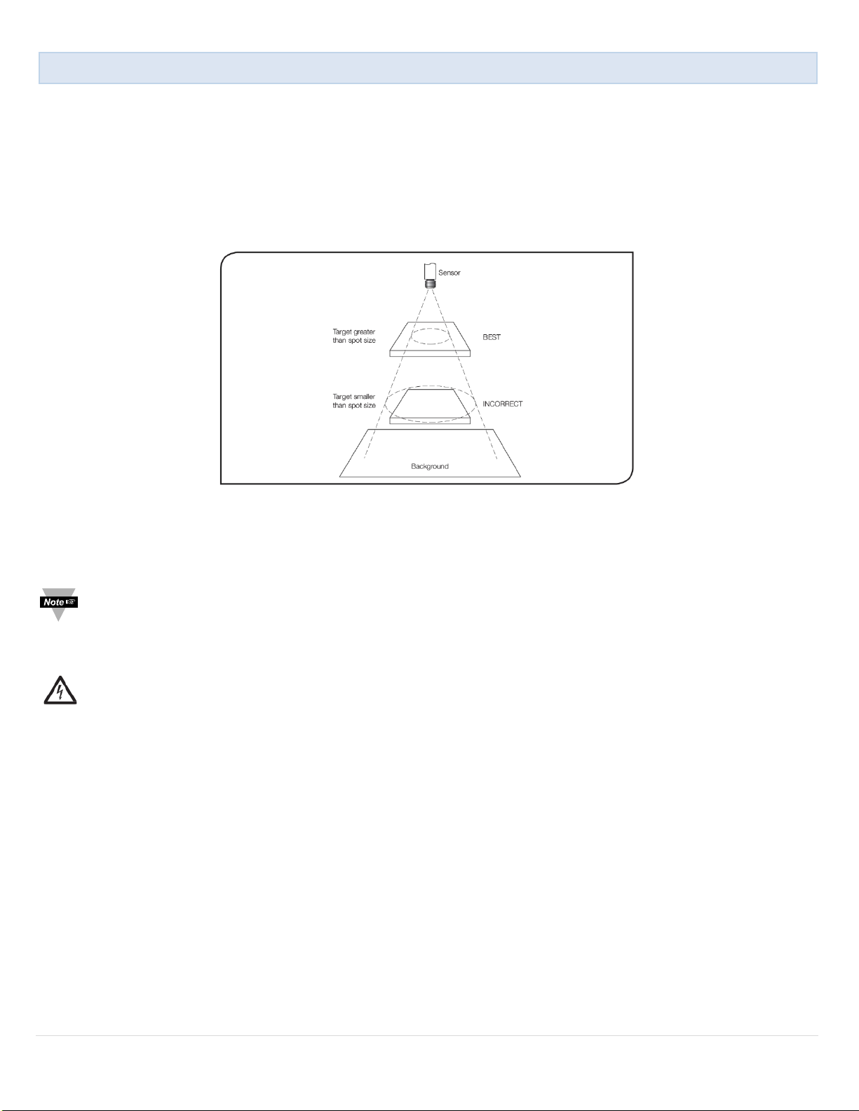
Ensure that the sensor is positioned so that it is focused on the target only.
Figure 5
Distance and Spot Size
The size of the area (spot size) to be measured determines the distance between the sensor and the target. The spot size
must not be larger than the target. The sensor should be mounted so that the measured spot size is smaller than the target.
Note: A mounting bracket for the SP-001 / SP-002 is sold separately.
Ambient Temperature
The sensor is designed to operate in ambient temperatures from -40°C to 85°C (-40°F to 185°F).
Caution: To avoid thermal shock, allow 20 minutes for the unit to adjust to large changes in ambient temperature.
Atmospheric Quality
Smoke, fumes, or dust can contaminate the lens and cause errors in temperature measurement.
Electrical Interference
To minimize electromagnetic interference or “noise,” the sensor should be mounted away from motors and generators.
7 | Page
Page 8
Software Setup
Mechanical Installation
The SP-001 / SP-002 requires a Smart Interface (IF-001-0) or Wireless Transmitter to connect to your computer. Locate the
position of the keyway as a guide on the SP-001 / SP-002 prior to making the connection. See Figure 6.
Figure 6
The sensor can be mounted on brackets, clamps or cutouts of your own design or you can use the fixed and adjustable
Omega mounting bracket accessory: SP-001-MB.
Note: SP-001-MB accessory is sold separately.
Ensure Omega Sync is running before continuing. The SP-001 / SP-002 Infrared Smart Sensor is configured exclusively
through the Omega Sync software. To connect your SP-001 / SP-002 to Omega Sync, follow these instructions.
Note: Omega Sync is available to download on the Omega website.
Connecting to Omega Sync – Automatic Detect
Once the SP-001 / SP-002 and Smart Interface are connected to your computer, Omega Sync will automatically detect it and
begin displaying temperature readings.
Note: If you have successfully connected your SP-001 / SP-002 to Omega Sync, skip ahead to section Setting
Emissivity. If you were not successful in connecting your device, proceed to Connecting to Omega Sync – Manual.
Connecting to Omega Sync – Manual
If Omega Sync does not automatically detect your device, follow these instructions to manually connect your device.
Step 1: Click on the icon located on the top left of the Omega Sync interface.
Step 2: Proceed through the Add Device Wizard and click End Device / Probe. See Figure 7.
Figure 7
8 | Page
Page 9
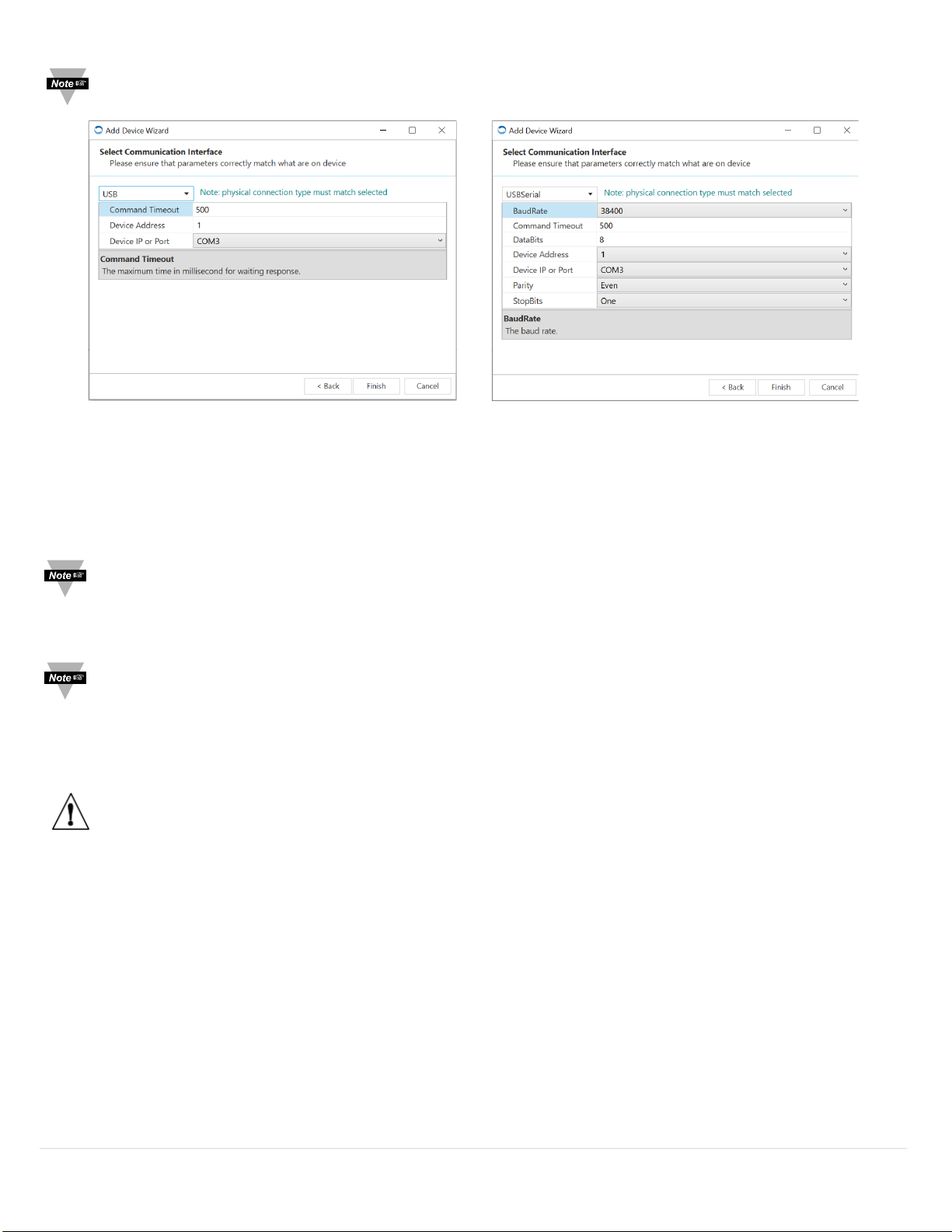
Note: The connection type and parameters must be accurate for a proper connection to be established. Failure to
accurately setup communication parameters may result in communication errors.
Figure 8 Figure 9
Communication Interface
• Connection Type: Select the type of connection you have between your SP-001 / SP-002 and your computer. USB
connection is displayed in Figure 8. USB Serial connection is displayed in Figure 9.
• Command Timeout: The maximum time (in milliseconds) for a command to be completed before the command is
aborted.
Note: The default command timeout is 500 milliseconds. It is recommended that this section be left alone to avoid
communication errors.
• Device Address: If your Smart Interface is part of a Network, enter the Network Address here. The default network
address is 1 for most devices. Please refer to the manual of your Smart Interface for more information.
Note: The default Device Address is 1. This should only be changed when seeking a specific Bus Network.
• Device IP or Port: The COM port number that your device is connected to on your computer.
Step 4: Adjust the communication parameters to the intended settings. Click Finish.
Important: The following parameters should NOT be changed.
• BaudRate: Controls bits per second
• DataBits: The number of ‘bits’ in each character sent.
• Parity: A means of checking correctness of character by adding an extra ‘bit’ to the character and setting the value
based on all the other bits in the character.
• StopBits: The number of ‘bits’ used to indicate the end of the character.
9 | Page
Page 10
Setting Emissivity
This manual will outline three ways to set the emissivity of the SP-001 / SP-002:
• Known Emissivity Value
• Setting Emissivity Value via Emissivity Table
• Setting Emissivity via Secondary Temperature Device
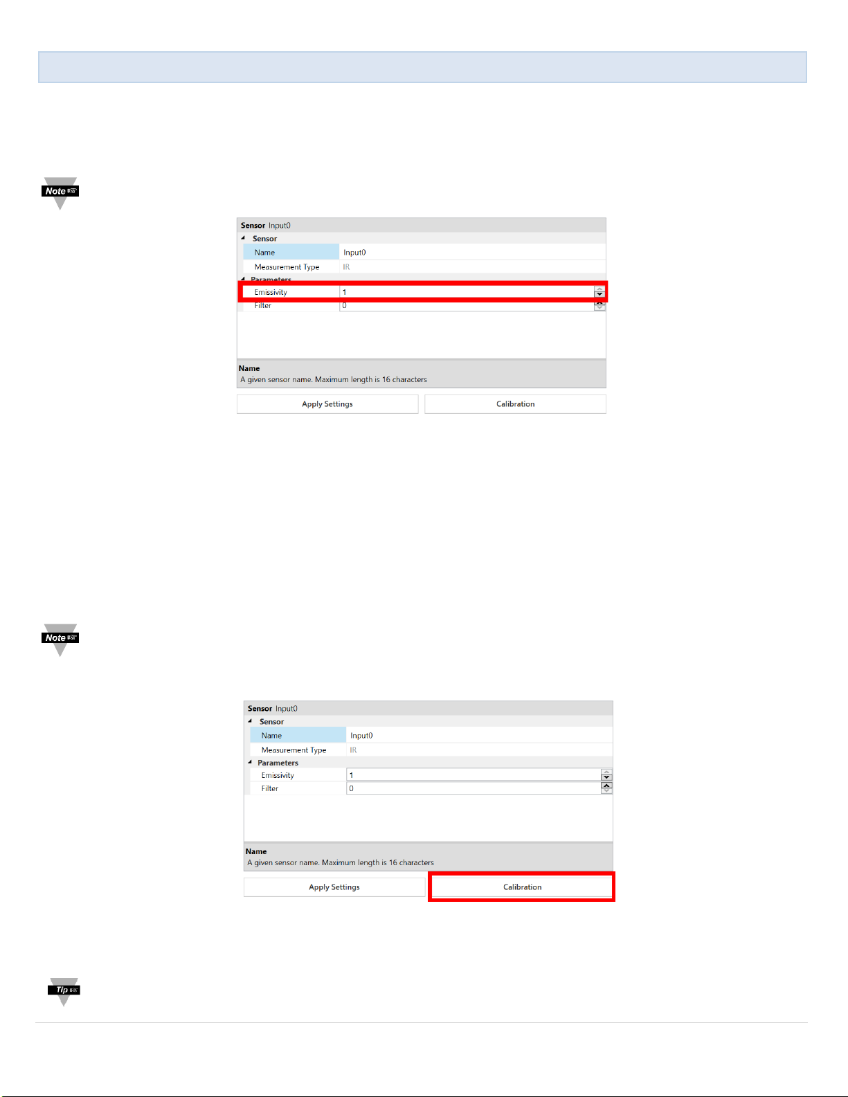
Note: The default factory setting for emissivity is set to 1.
Figure 10
Known Emissivity Value
If the emissivity of the target material is already known, you may enter it in the Emissivity Dropdown and click Apply
Settings to finalize changes. See Figure 10.
Setting Emissivity via Emissivity Table
For a list of reference materials and their corresponding emissivity values, refer to the Emissivity Table in Appendix A. Enter
the corresponding value in the Emissivity Dropdown and click Apply Settings to finalize. See Figure 10.
Setting Emissivity via Secondary Temperature Device
Note: Ensure the SP-001 / SP-002 is connected to Omega Sync and pointed at the material being measured at a
distance that covers the entire field of view.
Step 1: Click Calibration. See Figure 11.
Step 2: Use a secondary device to measure the temperature of the target material being measured by the SP-001 / SP-
002.
Tip: Recommended devices to measure the temperature of the target material include a thermocouple, RTD, etc.
Figure 11
10 | Page
Page 11
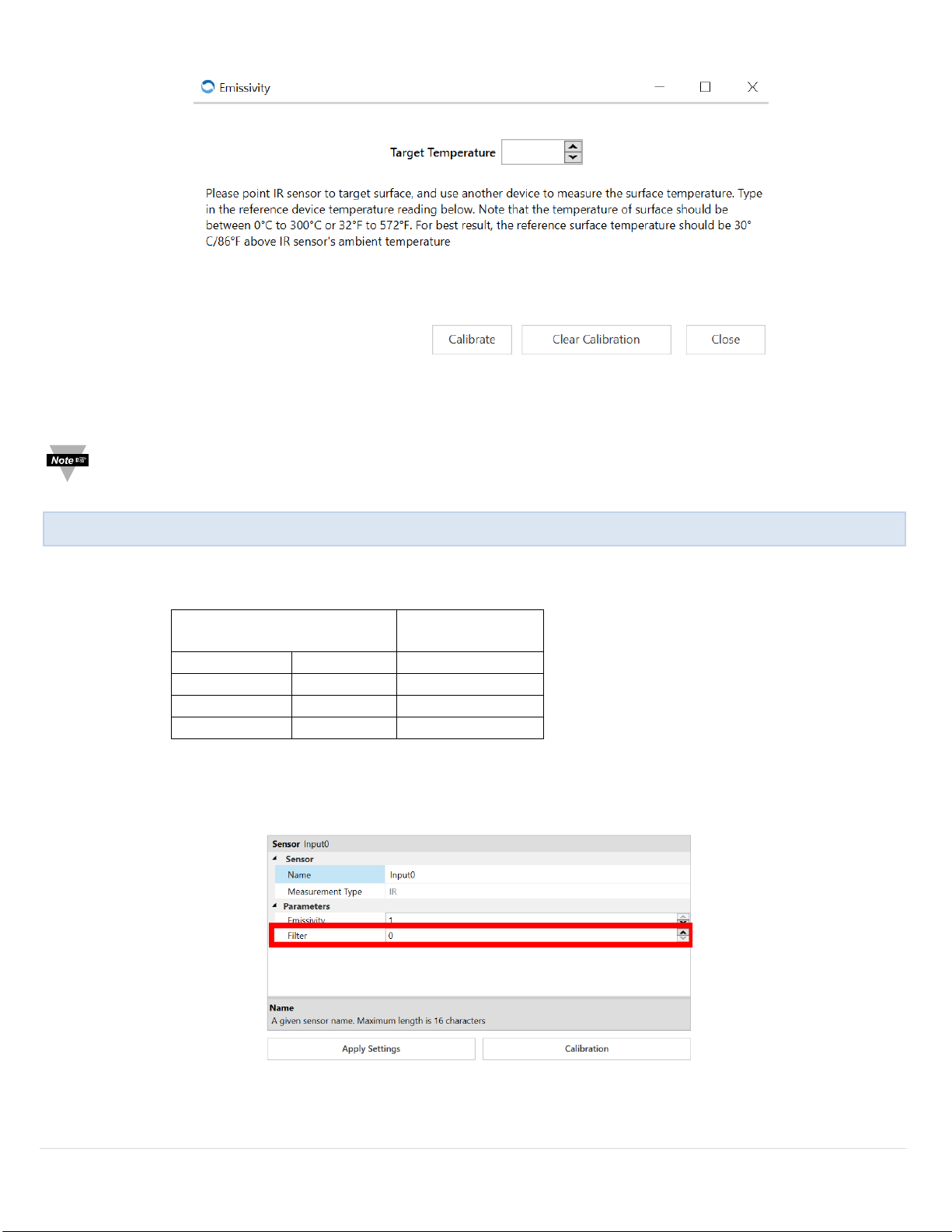
Step 3: Once the target temperature has been determined, enter the target temperature into Omega Sync. See Figure 12.
Filter Settings
Response
Time (Seconds)
Off 0 0.3
Low 1 0.4
Medium 2 0.5
High 3 1.5
Adjusting Spike and Noise Suppression
Figure 13
Figure 12
Step 4: Click Calibrate to set the emissivity changed and exit out of the calibration pop-up. Click Apply Settings to finalize.
Note: When you click Calibrate, the emissivity value in Figure 10 will change according to the value of the Target
Surface Temperature entered.
Filter settings are set to the following default factory settings:
Filter Settings: Low
These parameters provide a response time of 0.4 seconds.
To change the Filter settings, click the corresponding dropdown displayed in Figure 11 and the table provided.
Click Apply Settings when you are satisfied with the settings to finalize.
11 | Page
Page 12
Alarm Setting
Figure 14
Figure 15
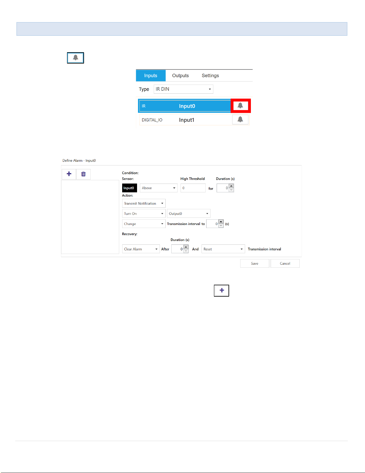
The SP-001 offers software adjustable alarms for your smart sensor. To begin alarm setup, follow these instructions.
Step 1: Click the icon next to the input you would like to customize.
Step 2: Customize alarm settings to your satisfaction. See Figure 15.
Once you have customized the settings for your preferred alarm, click the icon to add the alarm to your list, and click
Save to finalize.
12 | Page
Page 13

Material
Emissivity (ε)
Aluminum – pure highly polished plate . . . . . . . . . . . . . . . . . . . . . . . . 0.04 to 0.06
Appendix A
- Emissivity Table
Aluminum – heavily oxidized . . . . . . . . . . . . . . . . . . . . . . . . . . . . . . . 0.20 to 0.31
Aluminum – commercial sheet . . . . . . . . . . . . . . . . . . . . . . . . . . . . . . . . . . . . 0.09
Brass – dull plate . . . . . . . . . . . . . . . . . . . . . . . . . . . . . . . . . . . . . . . . . . . . . . 0.22
Brass – highly polished, 73.2% Cu, 26.7% Zn . . . . . . . . . . . . . . . . . . . . . . . . . 0.03
Chromium – polished . . . . . . . . . . . . . . . . . . . . . . . . . . . . . . . . . . . . . 0.08 to 0.36
Copper – polished . . . . . . . . . . . . . . . . . . . . . . . . . . . . . . . . . . . . . . . . . . . . . 0.05
Copper – heated at 600°C (1112°F) . . . . . . . . . . . . . . . . . . . . . . . . . . . . . . . . 0.57
Gold – pure, highly polished or liquid . . . . . . . . . . . . . . . . . . . . . . . . . 0.02 to 0.04
Iron and steel (excluding stainless) – polished iron . . . . . . . . . . . . . . . . 0.14 to 0.38
Iron and steel (excluding stainless) – polished cast iron . . . . . . . . . . . . . . . . . . . 0.21
Iron and steel (excluding stainless) – polished wrought iron . . . . . . . . . . . . . . . . 0.28
Iron and steel (excluding stainless) – oxidized dull wrought iron . . . . . . . . . . . . 0.94
Iron and steel (excluding stainless) – rusted iron plate . . . . . . . . . . . . . . . . . . . . 0.69
Iron and steel (excluding stainless) – polished steel . . . . . . . . . . . . . . . . . . . . . . 0.07
Iron and steel (excluding stainless) – polished steel oxidized at 600°C (1112°F) . . . . . . . . . . . . . . . . 0.79
Iron and steel (excluding stainless) – rolled sheet steel . . . . . . . . . . . . . . . . . . . . 0.66
Metals
Iron and steel (excluding stainless) – rough steel plate . . . . . . . . . . . . . . 0.94 to 0.97
Lead – gray and oxidized . . . . . . . . . . . . . . . . . . . . . . . . . . . . . . . . . . . . . . . 0.28
Mercury . . . . . . . . . . . . . . . . . . . . . . . . . . . . . . . . . . . . . . . . . . . . . 0.09 to 0.12
Molybdenum filament . . . . . . . . . . . . . . . . . . . . . . . . . . . . . . . . . . . . 0.10 to 0.20
Nickel – polished . . . . . . . . . . . . . . . . . . . . . . . . . . . . . . . . . . . . . . . . . . . . . . 0.07
Nickel – oxidized at 649 to 1254°C (1200 to 2290°F) . . . . . . . . . . . . 0.59 to 0.86
Platinum – pure polished plate . . . . . . . . . . . . . . . . . . . . . . . . . . . . . . 0.05 to 0.10
Platinum – wire . . . . . . . . . . . . . . . . . . . . . . . . . . . . . . . . . . . . . . . . 0.07 to 0.18
Silver – pure and polished . . . . . . . . . . . . . . . . . . . . . . . . . . . . . . . . . 0.02 to 0.03
Stainless steel – polished . . . . . . . . . . . . . . . . . . . . . . . . . . . . . . . . . . . . . . . . 0.07
Stainless steel – Type 301 at 232 to 941°C (450 to 1725°F) . . . . . . . . . 0.54 to 0.63
Tin – bright . . . . . . . . . . . . . . . . . . . . . . . . . . . . . . . . . . . . . . . . . . . . . . . . . 0.06
Tungsten – filament . . . . . . . . . . . . . . . . . . . . . . . . . . . . . . . . . . . . . . . . . . . . 0.39
Zinc – polished commercial pure . . . . . . . . . . . . . . . . . . . . . . . . . . . . . . . . . . 0.05
Zinc – galvanized sheet . . . . . . . . . . . . . . . . . . . . . . . . . . . . . . . . . . . . . . . . . 0.23
13 | Page
Page 14

Material
Emissivity (ε)
Asbestos Board. . . . . . . . . . . . . . . . . . . . . . . . . . . . . . . . . . . . . . . . . . . . . . . 0.96
Asphalt, tar, pitch. . . . . . . . . . . . . . . . . . . . . . . . . . . . . . . . . . . . . . . . 0.95 to 1.00
Brick – red and rough. . . . . . . . . . . . . . . . . . . . . . . . . . . . . . . . . . . . . . . . . . 0.93
Brick – fireclay. . . . . . . . . . . . . . . . . . . . . . . . . . . . . . . . . . . . . . . . . . . . . . . . 0.75
Carbon – filament. . . . . . . . . . . . . . . . . . . . . . . . . . . . . . . . . . . . . . . . . . . . . 0.53
Carbon – lampblack - rough deposit. . . . . . . . . . . . . . . . . . . . . . . . . . . 0.78 to 0.84
Glass - Pyrex, lead, soda. . . . . . . . . . . . . . . . . . . . . . . . . . . . . . . . . . . 0.85 to 0.95
Marble – polished light gray. . . . . . . . . . . . . . . . . . . . . . . . . . . . . . . . . . . . . . 0.93
Paints, lacquers, and varnishes – Black matte shellac. . . . . . . . . . . . . . . . . . . . 0.91
Paints, lacquers, and varnishes – aluminum paints. . . . . . . . . . . . . . . . . 0.27 to 0.67
Paints, lacquers, and varnishes – flat black lacquer. . . . . . . . . . . . . . . . 0.96 to 0.98
Non-Metals
Paints, lacquers, and varnishes – white enamel varnish. . . . . . . . . . . . . . . . . . . 0.91
Porcelain – glazed. . . . . . . . . . . . . . . . . . . . . . . . . . . . . . . . . . . . . . . . . . . . . 0.92
Quartz – opaque. . . . . . . . . . . . . . . . . . . . . . . . . . . . . . . . . . . . . . . . . 0.68 to 0.92
Roofing Paper. . . . . . . . . . . . . . . . . . . . . . . . . . . . . . . . . . . . . . . . . . . . . . . . 0.91
Tape – Masking. . . . . . . . . . . . . . . . . . . . . . . . . . . . . . . . . . . . . . . . . . . . . . . 0.95
Water. . . . . . . . . . . . . . . . . . . . . . . . . . . . . . . . . . . . . . . . . . . . . . . . . 0.95 to 0.96
Wood – planed oak. . . . . . . . . . . . . . . . . . . . . . . . . . . . . . . . . . . . . . . . . . . . . . . . . . . . . . . . .. . . . . . . . . . 0.90
14 | Page
Page 15

General Specifications
Measured Temperature Range:
-70 to +380°C (-94 to 716°F)
Accuracy @ Ambient of 0-50°C (32 to 122°F):
1°C (1.8°F) or 1% of reading, whichever is greater
Accuracy Over Entire Ambient Operating Range:
4°C (3.6 °F) or 3% of reading, whichever is greater
Repeatability:
1°C (1.8°F) or 1% of reading
Field of View:
SP-001 is 6:1
SP-002 is 10:1
Spectral Response:
5.5 to 14 microns
Emissivity:
0.01 to 1.00, software adjustable
Response Time:
30 to 1500 msec, adjustable
Outputs:
2x Open Drain 100 mA max
Power:
3.3 Vdc, 0.05 W max
Operating Temperature:
-40 to 85°C (-40 to 185°F) less than 95% RH, non-condensing
Housing:
Stainless steel, IP 67 (NEMA 6)
Dimensions:
12 OD x 114 mm L (0.47” x 4.49”)
Weight:
35 g (1.2 oz) Vibration Test
Frequency Range
10 Hz to 500 Hz
Acceleration
10 g
Duration
45 min per axis
Sweep
1 octave/min
Safety and Regulatory Compliance
Specifications
CE:
The product herewith complies with the essential requirements and other relevant provisions of the EMC Directive
2014/30/EU, and the Low Voltage Directive 2014/35/EU, and carries the CE-marking accordingly
The following CE Mark is affixed to this equipment.
The CE declaration is available at the website listed on the cover page of this manual.
15 | Page
Page 16

WARRANTY/DISCLAIMER
OMEGA ENGINEERING, INC. warrants this unit to be free of defects in materials and workmanship
for a period of 13 months from date of purchase. OMEGA’s WARRANTY adds an additional one (1)
month grace period to the normal one (1) year product warranty to cover handling and shipping
time. This ensures that OMEGA’s customers receive maximum coverage on each product.
If the unit malfunctions, it must be returned to the factory for evaluation. OMEGA’s Customer Service
Department will issue an Authorized Return (AR) number immediately upon phone or written request.
Upon examination by OMEGA, if the unit is found to be defective, it will be repaired or replaced at no
charge. OMEGA’s WARRANTY does not apply to defects resulting from any action of the purchaser,
including but not limited to mishandling, improper interfacing, operation outside of design limits,
improper repair, or unauthorized modification. This WARRANTY is VOID if the unit shows evidence of
having been tampered with or shows evidence of having been damaged as a
result of excessive corrosion; or current, heat, moisture or vibration; improper
specification; misapplication; misuse or other operating conditions outside of
OMEGA’s control. Components in which wear is not warranted, include but are not
limited to contact points, fuses, and triacs.
OMEGA is pleased to offer suggestions on the use of its various products. However,
OMEGA neither assumes responsibility for any omissions or errors nor
assumes liability for any damages that result from the use of its products
in accordance with information provided by OMEGA, either verbal or
written. OMEGA warrants only that the parts manufactured by it will be as
specified and free of defects. OMEGA MAKES NO OTHER WARRANTIES OR
REPRESENTATIONS OF ANY KIND WHATSOEVER, EXPRESS OR IMPLIED, EXCEPT
THAT OF TITLE, AND ALL IMPLIED WARRANTIES INCLUDING ANY WARRANTY OF
MERCHANTABILITY AND FITNESS FOR A PARTICULAR PURPOSE ARE HEREBY
DISCLAIMED. LIMITATION OF LIABILITY: The remedies of purchaser set forth herein are
exclusive, and the total liability of OMEGA with respect to this order, whether
based on contract, warranty, negligence, indemnification, strict liability or otherwise,
shall not exceed the purchase price of the component upon which liability
is based. In no event shall OMEGA be liable for consequential, incidental or special damages.
CONDITIONS: Equipment sold by OMEGA is not intended to be used, nor shall it be used: (1) as a
“Basic Component” under 10 CFR 21 (NRC), used in or with any nuclear installation or activity; or (2)
in medical applications or used on humans. Should any Product(s) be used in or with any nuclear
installation or activity, medical application, used on humans, or misused in any way, OMEGA assumes
no responsibility as set forth in our basic WARRANTY / DISCLAIMER language, and, additionally,
purchaser will indemnify OMEGA and hold OMEGA harmless from any liability or damage whatsoever
arising out of the use of the Product(s) in such a manner.
RETURN REQUESTS/INQUIRIES
Direct all warranty and repair requests/inquiries to the OMEGA Customer Service Department.
BEFORE RETURNING ANY PRODUCT(S) TO OMEGA, PURCHASER MUST OBTAIN AN AUTHORIZED
RETURN (AR) NUMBER FROM OMEGA’S CUSTOMER SERVICE DEPARTMENT (IN ORDER TO AVOID
PROCESSING DELAYS). The assigned AR number should then be marked on the outside of the return
package and on any correspondence.
The purchaser is responsible for shipping charges, freight, insurance and proper packaging to prevent
breakage in transit.
FOR WARRANTY RETURNS, please have the
following information available BEFORE
contacting OMEGA:
1. Purchase Order number under which the
product was PURCHASED,
2. Model and serial number of the product under
warranty, and
3. Repair instructions and/or specific problems
relative to the product.
OMEGA’s policy is to make running changes, not model changes, whenever an improvement is possible. This affords
our customers the latest in technology and engineering.
OMEGA is a trademark of OMEGA ENGINEERING, INC.
© Copyright 2019 OMEGA ENGINEERING, INC. All rights reserved. This document may not be copied, photocopied,
reproduced, translated, or reduced to any electronic medium or machine-readable form, in whole or in part, without the
prior written consent of OMEGA ENGINEERING, INC.
FOR NON-WARRANTY REPAIRS,
for current repair charges. Have the following
information available BEFORE contacting OMEGA:
1. Purchase Order number to cover the COST
of the repair,
2. Model and serial number of the product, and
3. Repair instructions and/or specific problems
relative to the product.
consult OMEGA
Page 17

Where Do I Find Everything I Need for
Process Measurement and Control?
OMEGA…Of Course!
Shop online at omega.com
TEMPERATURE
MU
Thermocouple, RTD & Thermistor Probes, Connectors, Panels & Assemblies
MU
Wire: Thermocouple, RTD & Thermistor
MU
Calibrators & Ice Point References
MU
Recorders, Controllers & Process Monitors
MU
Infrared Pyrometers
PRESSURE, STRAIN AND FORCE
MU
Transducers & Strain Gages
MU
Load Cells & Pressure Gages
MU
Displacement Transducers
MU
Instrumentation & Accessories
FLOW/LEVEL
MU
Rotameters, Gas Mass Flowmeters & Flow Computers
MU
Air Velocity Indicators
MU
Turbine/Paddlewheel Systems
MU
Totalizers & Batch Controllers
pH/CONDUCTIVITY
MU
pH Electrodes, Testers & Accessories
MU
Benchtop/Laboratory Meters
MU
Controllers, Calibrators, Simulators & Pumps
MU
Industrial pH & Conductivity Equipment
DATA ACQUISITION
MU Communications-Based Acquisition Systems
MU Data Logging Systems
MU Wireless Sensors, Transmitters, & Receivers
MU Signal Conditioners
MU Data Acquisition Software
HEATERS
MU
Heating Cable
MU
Cartridge & Strip Heaters
MU
Immersion & Band Heaters
MU
Flexible Heaters
MU
Laboratory Heaters
ENVIRONMENTAL
MONITORING AND CONTROL
MU
Metering & Control Instrumentation
MU
Refractometers
MU
Pumps & Tubing
MU
Air, Soil & Water Monitors
MU
Industrial Water & Wastewater Treatment
MU
pH, Conductivity & Dissolved Oxygen Instruments
M
5744/0919
 Loading...