

Page 1

OPERATING & INSTALLATION
INSTRUCTIONS
RS-3
DELUXE MODULAR REMOTE CAR STARTER
FOR AUTOMATIC TRANSMISSION VEHICLES ONLY
COPYRIGHT: OMEGA RESEARCH & DEVELOPMENT 1999
1
INTRODUCTION & WARNINGS
Congratulations on your purchase of the RS-3 Remote Car Starter. The RS-3
will allow you to start your vehicle's engine from the comfort of your home or
office, allowing your vehicle to warm up in winter and cool down in summer. When
you leave your vehicle, simply set the climate controls for what you desire to be
operating upon remote start - heater, defroster or air conditioning.
The RS-3 is an "Add-On" unit designed to be used in conjunction with another
remote control unit such as a remote vehicle security or keyless entry system.
We highly recommend that this system be professionally installed, as the complexity of the modern automobile and the nature of circuits to be accessed is often
beyond the abilities of most do-it-yourselfers.
There are several safety considerations with using and installing the RS-3 Remote Car Starter. Among them are:
- This unit is for Automatic Transmission vehicles only. Installation in a manual
transmission equipped vehicle can result in property damage or personal injury.
- This unit is for fuel injected gasoline engines only.
- Children should not be left unattended in, or be allowed to play with the activat
ing transmitters of a remote starter equipped vehicle.
- Do not use this unit in an enclosed structure or garage.
4
INDEX:
Operating Instructions:
Introduction & Warnings ......................................................................... 4
Remote Starting .................................................................................... 5
Valet Override Mode ............................................................................... 6
Installation Instructions:
Warnings ........................................................................................... 7-8
5-Wire Connector .............................................................................. 9-11
3-Wire Blue Connector ..................................................................... 12-13
7-Wire Connector ............................................................................ 14-24
Engine Detect (Smart, Tach, Vacuum) ................................................. 21-23
Features Programing ............................................................................ 25
Wiring Diagram .................................................................................... 26
3
REMOTE STARTING
To Remote Start The Vehicle: Press the necessary button combination on
the host system's transmitter.
1) The parking-lights will flash once then turn On to confirm Start process.
2) The ignition circuit will turn On.
3) Within 2 seconds the parking lights will turn Off and the starter will engage.
4) The engine will start to run and the starter will be disengaged.
5) The parking lights will stay On while the RS unit is controlling the engine.
6) If the engine stalls, the RS unit will make two attempts to restart it.
7) After 15/30 minutes (programmable) the RS unit will turn the engine off.
- Upon entering the vehicle place the ignition key in the switch and turn it to
the "On" position. Do not turn the key to the "Start" position.
Safety Features
- The RS unit will only engage if the gear shift selector is in "Park".
- The unit will not engage if the hood is opened.
Deactivation
- To stop the engine by remote control, simply press transmitter button #3 again.
- Stepping on the brake pedal prior to inserting the key will deactivate the RS unit.
- Opening the hood will deactivate the RS unit.
5
Page 2
VALET OVERRIDE MODE
Valet Override: The position of the Override switch allows or prevents the RS
unit from being activated. This feature is used when you do not wish the unit to
be operated, such as when you leave it with a valet parking attendant, mechanic
or if you loan your car to another person.
To engage the Valet Override mode, simply turn the Override Switch OFF. It is
recommended to always turn the Override Switch OFF to prevent unintentional
or unauthorized use of the Remote Car Starter.
Note: Do not confuse the toggle type Valet Override switch with the push button
programming button.
INSTALLATION INSTRUCTIONS
!! WARNINGS !!
Do not attempt to install this Remote Car Starter into a manual transmission
vehicle! Doing so could cause serious property damage, personal injury,
and will void all warranties!
Be aware of, and avoid, any airbag circuitry! Due to the fact that an installer
will not be in a normal, upright seated position, severe injury may occur in
an accidental airbag deployment!
The use of a Digital Multimeter (DMM) or Volt-Ohm Meter (VOM) instead of a
standard testlight is recommended. This can greatly reduce the risk of an
accidental airbag deployment or on-board computer damage.
Battery gases are explosive! Avoid sparks and do not smoke while working
near the vehicle's battery!
Always protect wires ran through the firewall from sharp metal edges and
hot parts of the engine! Always fuse positive wires at the battery or power
source!
6
IMPORTANT!
After reading this manual, start the installation by affixing the
WARNING DECAL to a visible area in the engine compartment!
Installation Considerations: This entire booklet should be read before start-
ing the installation. An understanding of which control module wires are to be
used and their functions is essential. Installations will vary from car to car, as
some control module wires are required, while others are optional. Before starting
the installation, it should be determined which control module wires will be used.
Most installers will list these wires, then "map out" the installation by locating and
noting the target wires in the vehicle. This will also determine the best location for
the RS control module, which is mounted upon completion of the installation.
This Remote Start Unit duplicates the actions that occur within the ignition switch
when you use your key to start the engine. Because of this, most of the main
wiring harness connections will be made at the ignition switch harness. The ignition switch wires usually are high amperage circuits, which means that high reliability connections must be made! We recommend proper soldering of all connections.
Caution!
cased in Yellow or Red tubing or sleeves. Do not use a standard test light, as it
can deploy an airbag or damage on-board computers and sensors.
Avoid the Airbag circuit!
Especially avoid any harness or wires en-
8
7
W I R I N G - 5 WIRE CONNECTOR
Red Wire: (Two 12-Gauge wires)
Connect both Red wires to constant 12 Volts. The most common sources are
the battery's Positive terminal and the ignition switch wiring harness (See diagram
#
1).
Connection Required
Diagram #1
Recommended Locations
Ignition Switch Wire Locations
9
Page 3
Green Wire: 12-Gauge
Connection Required
Connect the Green wire to the vehicle's Starter Motor wire. This wire will show
12 volts only when the ignition key is in the "Start" position. This wire is also found
in the ignition switch wiring harness (See diagram
#
1 on page 9). Some vehicles have
a second Starter wire known as a "Cold Start" wire. When this is encountered, if
the two Starter wires are the same circuit you may connect both of these wires to
the Green wire. If the two Starter wires are separate circuits an optional prewired
dual relay socket and relays are recommended.
Note: If a security system is present which utilizes a starter interrupt circuit, the
Green wire must be connected to the Starter Motor side of the interrupt.
Yellow Wire: 12-Gauge
Connection Required
Connect the Yellow wire to the vehicle's Accessory wire. This circuit supplies
power to the Heat, Ventilation and Air Conditioning (HVAC) system. This wire will
show 12 Volts when the ignition key is in the "Run" and "Accessory" positions and
No voltage in the "Start" and "Off" positions. The connection point for this wire is
also found in the ignition switch wiring harness (See diagram
#
1).
Note: If two or more Accessory wires are present, you will need to connect an
optional relay(s) to the thin Yellow wire located in the 3-pin Blue connector (See
diagram
#
3 on page 13).
Blue Wire: 12-Gauge
Connection Required
Connect the Blue wire to the vehicle's Ignition #1 wire (also known as Primary
Ignition)
. This wire will show 12 Volts when the ignition key is in the "Run" and
"Start" positions and no voltage in the "Off" and "Accessory" positions. This wire is
found in the ignition switch wiring harness (See diagram
#
1).
Note: If two or more Primary Ignition wires are present, you will need to connect an
optional relay(s) to the thin Blue wire located in the 3-pin Blue connector (See
diagram
#
2 on page 13).
10
W I R I N G - 3 WIRE "BLUE" CONNECTOR
Blue Wire: (22 Gauge)
The Blue wire will supply a 500ma Negative Ignition output that can be used to
operate an optional relay(s) if two or more Primary Ignition wires are present in the
vehicle. If an optional relay(s) is needed, Connect the Blue wire to the Negative
side of the relay's coil (See diagram
#
2 on page 13).
Red Wire: (22 Gauge)
The Red wire supplies constant 12 Volts that can be used to power the relay's
coil.
Warning: DO NOT use the Red wire to power the Ignition or Accessory circuits.
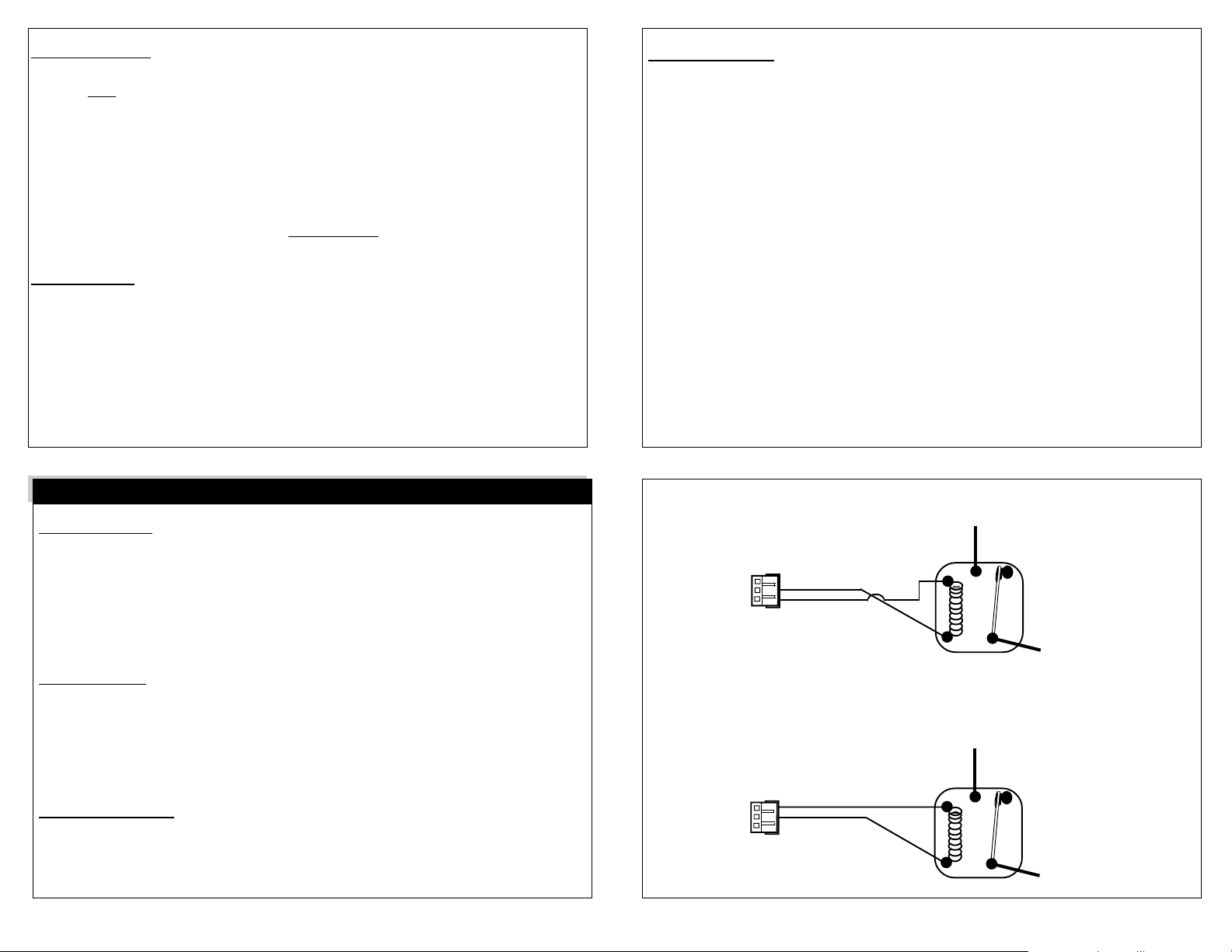
Diagram #2
Red Wire
Blue Wire
11
Fused
constant
12 Volts
85
87
Coil
86
Fused
constant
12 Volts
87a
30
Relay
Ignition Circuit
Yellow Wire: (22 Gauge)
The Yellow wire will supply a 500ma Negative Accessory output that can be used
to operate an optional relay(s) if two or more Primary Accessory wires are present
in the vehicle. If an optional relay(s) is needed, Connect the Yellow wire to the
Negative side of the relay's coil (See diagram
12
#
3 on page 13).
Diagram #3
Yellow Wire
Red Wire
13
85
Coil
86
87
87a
30
Relay
Accessory Circuit
Page 4

W I R I N G - 7-WIRE CONNECTOR
12345
12345
12345
12345
12345
12345
12345
12345
12345
12345
4
4
4
4
4
4
4
4
4
12
12
12
12
Black Wire:
Connection Required
Connect the Black wire to a very good, clean chassis ground. Recommended
areas are to an existing machine thread bolt, either in the driver's kick panel area
or a major structural member behind the dash (see diagram #4). Small dash braces
are not adequate, and the area must be clean, bright metal. Use the largest existing machine threaded bolt available. Using a sheet metal screw or grounding to
sheet metal is inadequate (see diagram #5 on page 15).
Diagram #4
Black Wire
Control Module
14
White Wire:
The function of the White wire is to supply a 12 Volt signal to the vehicle’s
exterior parking-lights in order to visually confirm system operations.
Connect the White wire to the vehicle's 12 Volt parking-light circuit (See diagram
on page 17).
-The correct wire will show 12 Volts only when the headlight switch is in the "Parking
Light" and "Head Light" positions.
-This wire can usually be found at the headlight switch.
Connection If Desired
#
Diagram #5
Self-Tapping Screw
"Star" Washer
Black Wire
15
Diagram #6
6
Dash Board
Lights
White Wire
Control
Module
Ring Terminal
Light
Switch
23
23
23
23
23
23
23
23
23
Parking Lights
Note #1: When such a wire is located, be sure to also test that it is non-rheostated:
While metering the wire, operate the dash light dimmer control. The correct wire will
show no change in voltage when the dimmer is operated.
Note #2: Some vehicles have a parking-light relay which is triggered by a Negative
signal from the headlight switch. In these vehicles, the White wire must be
connected after the relay, usually at the Fuse/Junction Block.
Note #3: Some vehicles are equipped with a split parking light system. In these
vehicles, the use of IN4006 diodes are required (see diagram #7 on page 17).
WARNING:
- Do NOT connect the white wire directly to the vehicle’s headlights. An
external relay is required.
16
Diagram #7
Control
Module
Note: Use Two IN4006 Diodes.
White Wire
Right Side Circuit
Light
Switch
Left Side Circuit
Connecting Separate Left And Right Parking Lights Using Two Diodes.
17
Parking Lights
Page 5

Dark Blue Wire:
The hood pin switch must be installed. It prevents operation of the RS unit
if the hood is open.
Connect the Dark Blue wire to the hood pin switch. Carefully route the Dark Blue
wire through the firewall, using an added or existing grommet. Avoid any hot or
moving parts. Mount the switch so that it is open (pin down) when the hood is shut
and closed (pin up) when the hood is open.
If there is an existing hood pin switch for an alarm system, you may use it for
the Dark Blue wire connection; diode-isolation is recommended.
Connection Required
Remote Start Override Mode:
The RS unit can be placed into an "Override" mode which will prevent it from
starting the vehicle. This mode is for situations when it is not convenient or safe
for the Remote Start feature to be operable. For example during extended stopovers for vehicle servicing, maintenance, valet parking, washing, etc.
Connect the Dark Blue wire to one of the included toggle switch's two wires. Connect the toggle switch's remaining wire to ground.
Optional Parts Needed:
Two IN4002 Diodes
To Existing Alarm
Instead of using a pin switch to monitor the hood's open or shut status, an Omega
AU-46 Mercury Tilt Switch may used. Connect one of the AU-46's wires to Negative Chassis Ground and connect the remaining wire to the Dark Blue wire.
Hood
Pin
Switch
18
Yellow/Black Wire:
Diagram #8
Dark Blue Wire
Connection
Required
The Yellow/Black wire must be connected. It is part a critical safety feature
which disables the RS unit whenever the brake pedal is pressed.
Connect the Yellow/Black wire to the brake switch wire which shows 12 Volts
when the brake pedal is pressed. The brake switch is typically located above the
brake pedal, and usually mounted to the brake pedal support bracket. Always
make this connection in a fashion ensuring its long-term reliability; soldering is
highly recommended. Upon completing the Yellow/Black wire's connection, thoroughly test the operation of this circuit.
Diagram #9
Ground
Orange/Black Wire:
The Orange/Black wire is the engine detect wire. The RS unit utilizes three
different methods of monitoring the vehicle during the remote starting process.
Consider all methods before deciding which one to use. Normally the Smart Start
method is used.
Hood
Pin
Switch
Dark Blue Wire
Control
Module
19
Connection Required
1) Vacuum Switch Sensing:
This method uses a Vacuum switch to verify that the vehicle' engine is running.
The Orange/Black wire connects to one of the Vacuum switch's wires, the other
wire is connected to chassis Ground. Connect the Vacuum switch using a "T"
connector to a vacuum hose on the engine's intake manifold.
Pink Wire:
The Pink wire activates the RS Unit. If the Pink wire receives a Negative
pulse, the RS unit will start the vehicle's engine, provided that all safety circuits
are in the proper status. After the engine has been started by remote control,
another Negative pulse on the Pink wire will turn the RS unit off, stopping the
engine.
Connect the Pink wire to an available auxiliary output of an existing Remote
Security or Keyless Entry System.
20
Connection If Desired
1) Position the 3-way selector switch for Vacuum switch operation (right position).
2) Locate the Smart Start & Tach Sense adjustment screws and LED indicators.
3) Turn BOTH adjustment screws completely counterclockwise.
Note: Using a multimeter set to Ohms, measure the resistance of the Vacuum
switch. The switch should read Zero resistance when the engine is "Off" and
read Maximum resistance (open circuit) when the engine is running. If this is not
the case, relocate the vacuum connection.
21
Page 6

2) Smart Start:
This method uses a voltage sensing circuit which reads the vehicle's voltage before attempting to start, and then monitors for a voltage increase which occurs
when the alternator has output. The Orange/Black wire connects to a constant 12
Volt source (i.e.: the vehicle's battery).
Note: When using this method Programmable Jumper #3 will increase/decrease
the starter motor cranking time.
1) Position the 3-way selector switch for Smart Start (center position).
2) Locate the Smart Start & Tach Sense adjustment screws and LED indicators.
3) Turn BOTH adjustment screws completely counterclockwise.
4) Start the vehicle.
5) Begin tuning the Smart Start adjustment screw slowly clockwise until the LED
indicator begins to flash. The flashes confirm that the unit is sensing the engine.
6) Turn the vehicle Off.
7) Confirm that the unit is not picking up noise from other vehicle circuits:
a. Without starting the engine, turn the ignition key to the "On" position.
b. If the LED indicator remains "Off" the unit has been properly tuned.
c. If the LED indicator flashes there is noise on the Orange/Black wire's connec tion and it will be necessary to relocate the connection.
22
3) Tach Sense:
If the vehicle is generally hard to start (requiring the starter to be engaged for more
than 1 second)
method the Orange/Black wire reads the engine speed (tach) information from a
wire in the vehicle. The Orange/Black wire connects to the vehicle's tach wire,
which is found in the engine compartment, although in some cases it may also be
located inside the vehicle. To use a multimeter to verify the correct tach wire, set
it for AC Volts scale. The correct wire will read 1 to 6 volts AC with the engine
idling, and will increase with engine speed.
Note: When using this method Programmable Jumper #1 will increase/decrease
the unit's sensitivity.
1) Position the 3-way selector switch for Tach Sense (left position).
2) Locate the Tach Sense & Smart Start adjustment screws and LED indicators.
3) Turn BOTH adjustment screws completely counterclockwise.
4) Start the vehicle.
5) Begin tuning the Tach Sense adjustment screw slowly clockwise until the LED
indicator illuminates solid, then turn the vehicle Off.
- To increase the crank time, tune the adjustment screw counterclockwise.
- To decrease the crank time, tune the adjustment screw clockwise.
this method will produce more consistent remote starting. With this
23
Orange Wire:
Connection If Desired
The function of the Orange wire is to provide a Negative 250ma auxiliary out-
put which may be used to operate a starter motor "Anti-Grind" relay.
Connect "Switch" side of cut wire
to terminal #30 of the relay.
Ignition Switch
Connect "Motor" side of cut wire
Note: Connect 12-gauge
motor side of the cut wire
87a
87
86
Coil
#
to terminal
Green starter wire to the
87a of the relay.
30
85
Orange Wire
Control
Module
Starter Motor
Diagram #10
24
FEATURES PROGRAMING
The RS unit has three Jumper selectable programmable features. Whenever a
jumper setting is changed, it is necessary to power down the RS unit for the
change to be recognized.
Jumper Jumper
Feature "In" Removed
Jumper #1 Tach Sense Sensitivity Normal High
Jumper #2 Engine Running Time 15 Minutes 30 Minutes
Jumper #3 Starter Motor Cranking Time 1.2", 1.5", 2" 1", 1.5", 2"
25
Page 7

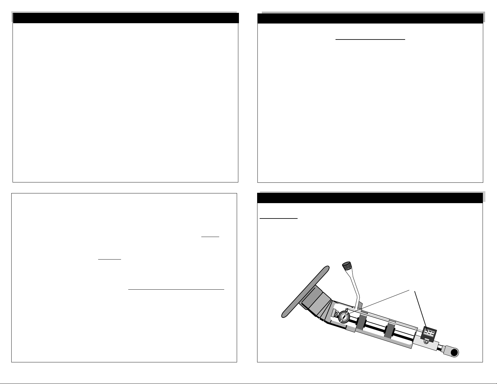
5 Wire Connector
3-Wire Blue Connector
7-Wire Connector
Engine Detect Selector Switch
Trap Door
Jumpers
4 3 2 1
Smart Start
Tuner & LED
Tach Sense
Tuner & LED
Vacuum Sensing
Smart Start
Tach Sensing
26
Green = Starter
Yellow = Accessory
Red = +12 Volts
Red = +12 Volts
Blue = Ignition 1
Yellow = - Accessory 2 Output
Red = Constant +12 Volts Output
Blue = - Ignition 2 Output
Black = Chassis Ground
White = + Parking Lights Output
Dark Blue = - Hood Pin Switch Input
Yellow/Black = + Brake Pedal Input
Pink = - Activation Input
Orange/Black = Engine Detect Wire
Orange = Anti-Grind Output
LIMITED LIFETIME WARRANTY
Products manufactured and sold by OMEGA RESEARCH & DEVELOPMENT, INC.
(the Company), are warranted to be free from defects in materials and workmanship
under normal use. If a product sold by the Company proves to be defective, the
Company will repair or replace it free of charge within the first year and thereafter all
parts to be repaired will be free with only a nominal charge for Omega Research and
Development, Inc.'s labor and return shipping, to the original owner during the lifetime
of the car in which it was originally installed.
All products for warranty repair must be sent postage prepaid to Omega Research
& Development, Inc., P.O. Box 508, Douglasville, Georgia 30133, with bill of sale or
other dated proof of purchase. This warranty is nontransferable and does not apply to
any product damaged by accident, physical or electrical misuse or abuse, improper
installation, alteration, any use contrary to its intended function, unauthorized service,
fire, flood, lightning, or other acts of God.
This warranty limits the Company's liability to the repair or replacement of the
product. The Company shall not be responsible for removal and/or reinstallation
charges, damage to or theft of the vehicle or its contents, or any incidental or
consequential damages caused by any failure or alleged failure of the product to
function properly. Under No Circumstances Should This Warranty, Or The Product
Covered By It, Be Construed As A Guarantee Or Insurance Policy Against Loss. The
Company neither assumes nor authorizes any person or organization to make any
Warranties or assume any liability in connection with the sale, installation, or use of this
product.
28
 Loading...