

Page 1

TM
User’s Guide
IR-USB
RH-USB Probe
TJ-USB Probe
Shop online at
omega.com
e-mail: info@omega.com
For latest product manuals:
www.omegamanual.info
UTC-USB Connector
PX409-USB
Probes, Sensors, Connectors, and
USB SERIES
Pressure Transducers
Page 2

omega.com info@omega.com
Servicing North America:
U.S.A. Omega Engineering, Inc.
Headquarters: Toll-Free: 1-800-826-6342 (USA & Canada only)
Customer Service: 1-800-622-2378 (USA & Canada only)
Engineering Service: 1-800-872-9436 (USA & Canada only)
Tel: (203) 359-1660 Fax: (203) 359-7700
e-mail: info@omega.com
For Other Locations Visit omega.com/worldwide
The information contained in this document is believed to be correct, but OMEGA accepts no liability for any errors it contains, and reserves
the right to alter specifications without notice.
Page 3

USB Series Probes, Sensors, Connectors, and Pressure Transducers
Table of Contents
Section ..............................................................................................................Page
Section 1 Introduction ......................................................................................... 1-1
1.1 Precautions ................................................................................................ 1-1
1.2 Safety Warnings and IEC Symbols ........................................................ 1-1
1.3 Statement on CE Marking ....................................................................... 1-2
1.4 General Description .................................................................................. 1-2
Section 2 Hardware ............................................................................................. 2-1
2.1 Package Inspection ................................................................................... 2-1
2.2 Included Items .......................................................................................... 2-1
2.3 IR-USB Accessories ................................................................................... 2-1
2.3.1 IR-USB Accessories Dimensions ................................................... 2-2
2.3.2 Laser Sighting Accessory Operation ............................................. 2-4
Section 3 Software ............................................................................................... 3-1
3.1 Getting Started .......................................................................................... 3-1
3.2 Software Installation Requirements .........................................................3-1
3.3 Software Installation ................................................................................ 3-1
3.4 TRH Central Measurement and Recording Program .......................... 3-6
3.4.1 Main Tab Menu ................................................................................ 3-6
3.4.2 Channel Configuration ................................................................... 3-7
3.5 Chart Tab ................................................................................................... 3-8
3.6 Data Log Tab ........................................................................................... 3-12
Section 4 Specifications ...................................................................................... 4-1
Section 5 Emissivity Table (For IR-USB Models) ......................................... 5-1
i
Page 4

USB Series Probes, Sensors, Connectors, and Pressure Transducers
Table of Figures
Figure Description Page
Section 1 Introduction
1-1 IEC Symbols ........................................................................................ 1-1
1-2 TJ-USB Overall Dimensions ............................................................. 1-2
1-3 RH-USB Dimensions ......................................................................... 1-2
1-4 UTC-USB Dimensions ....................................................................... 1-3
1-5 PX409-USB Dimensions .................................................................... 1-3
1-6 IR-USB Dimensions ........................................................................... 1-3
Section 2 Hardware
2-1 Mounting Bracket, OS100-MB .......................................................... 2-2
2-2 Water Cooling Jacket, OS100-WC ................................................... 2-3
2-3 Typical Water Cool Jacket Assembly .............................................. 2-3
2-4 Air Purge Collar, OS100-AP .............................................................. 2-3
2-5 Laser Sighting Accessory, OS100-LS ............................................... 2-4
2-6 Laser Warning Label ......................................................................... 2-5
Section 3 Software
3-1 Welcome Screen ................................................................................. 3-1
3-2 Install Options Screen ........................................................................ 3-2
3-3 Select Install Folder Screen ............................................................... 3-2
3-4 License Agreement Screen ................................................................ 3-3
3-5 Confirm Installation Screen .............................................................. 3-3
3-6 Welcome to the Device Driver Installation Wizard Screen ......... 3-4
3-7 Device Driver Installation Wizard Screen ...................................... 3-4
3-8 Completing the Device Driver Installation Wizard Screen ......... 3-5
3-9 Installation Complete Screen ........................................................... 3-5
3-10 Channel Tab Screen ........................................................................... 3-6
3-11 TRH Central Program Screen ........................................................... 3-6
3-12 Channel Configuration Screen .......................................................... 3-7
3-13 Chart TAB Menu Screen ................................................................... 3-8
3-14 Charting Screen .................................................................................. 3-8
3-15 Start Data Logging/Plotting Screen ................................................ 3-9
3-16 Configure Axis Screen ..................................................................... 3-10
3-17 Charting Options Screen ................................................................. 3-10
3-18 Data Log TAB Screen ....................................................................... 3-12
3-19 Data Logging Screen ........................................................................ 3-13
3-20 Start Data Logging/Plotting Screen .............................................. 3-13
Section 4 Specifications
4-1 Optical Field of View ......................................................................... 4-1
ii
Page 5

Section 1 - Introduction
Please read this manual completely before installing and operating your USB
based probe, connector, or pressure transducer.
It’s important to read and follow all notes, cautions, warnings and safety
precautions before operating this device.
1.1 Precautions
• This device is not designed for use in medical or nuclear applications.
• Do not operate this device in flammable or explosive environments.
• Do not operate this device outside of the recommended use outlined in
There are no user serviceable parts inside your device. Attempting to repair or
service your unit may void your warranty:
this manual.
NOTE:
Introduction
1
1.2 Safety Warnings and IEC Symbols
This device is marked with international safety and hazard symbols in
accordance with IEC standards. It is important to read and follow all precautions
and instructions in this manual before operating or commissioning this device as
it contains important information relating to safety and EMC. Failure to follow
all safety precautions may result in injury and or damage to your device. Use of
this device in a manner not specified will void your warranty
IEC symbols Description
Caution, refer to accompanying documentation
EU’s Waste Electrical and Electronic
Figure 1-1. IEC Symbols
Equipment Compliance
1-1
Page 6

1
DIMENSIONS mm (in)
Introduction
1.3 Statement on CE Marking
1.4.1 CE Marking
It is the policy of OMEGA to comply with all worldwide safety and EMI/
EMC regulations that apply. OMEGA is constantly pursuing certification of its
products to the European New Approach Directives. OMEGA will add the CE
mark to every appropriate device upon certification.
1.4 General Description
1.4.1 General Description
TJ-USB: Type-K Thermocouple probes with direct USB connection features a
rugged transition joint construction.
RH-USB: Relative Humidity/Temperature Probe with direct USB connection
features a rugged Stainless Steel Housing.
UTC-USB: Patented Universal Thermocouple Connector/Converter with USB
output.
PX409-USB: Pressure Transducer with direct USB connection, features a micromachined silicon sensor and 316L stainless steel wetted parts.
IR-USB: Infrared temperature sensor with direct USB connection.
1.4.2 Overall Dimensions
457.18 (18.0) or 609.6 (24.0)
STANDARD
Ø 4.8 (3/16) or Ø 6.4 (1/4)
Figure 1-2. TJ-USB Overall Dimensions
Ø 16 (5/8)
TJ-USB-CASS-316-18-K1
OMEGA.COM
88.9 (3-1/2)
28.8
(1-1/8)
914.4 (36.0)
All models feature an integral 2m (6’) shielded output cable and free user
software that converts your PC into a humidity, or temperature or pressure strip
chart data logger.
21
(13/16)
DIMENSIONS: mm (in)
46 (1-13/16)
2m (6 ft)
131 (5.18)
Ø 16 (5/16)
1-2
Figure 1-3. RH-USB Dimensions
Page 7

THERMOCOUPLE
CONNECTION
1/4-18NPT PRESSURE
ADAPTER
25.4 (1.00)
MODEL NO:
PRESSURE RA
OUTPUT:
SERIAL NO:
0 TO 5V
1234
PX3
82.5 (3.25)
-
UNIVERSAL
THERMOCOUPLE CONNECTOR
TC
UTC-USB
+
R
omega.com
Figure 1-4. UTC-USB Dimensions
GAGE
VENT
Ø 22.4 (0.88)
OMEGADYNE
R
OM
SU
USB
DIMENSIONS mm (in)
15.88
(0.63)
2 m (6 ft)
Introduction
USB CONNECTION
POWER LED
1
HEX 1.0 AF
HEX 0.87 AF
1/4-18 NPT PRESSURE
ADAPTER
HEX 0.87 AF
1/4-18 NPT PRESSURE
ADAPTER
104.1 (4.1)
7.6 (0.3)
PX 409 USB SERIES PRESSURE RANGES 15 PSIG AND BELOW
MODEL NO:
PRESSURE RA
OUTPUT:
SERIAL NO:
OMEGADYNE
R
0 TO 5V
OM
1234
SU
PX3
104.1 (4.1)
7.6 (0.3)
PX 409 USB SERIES PRESSURE RANGES 30 PSIG TO 1000PSIG.
MODEL NO:
PRESSURE RA
OUTPUT:
SERIAL NO:
OMEGADYNE
R
0 TO 5V
OM
1234
SU
PX3
119.4 (4.7)
7.6 (0.3)
DIMENSIONS mm (in)
PX 409 USB SERIES PRESSURE RANGES ABOVE 1000PSIG.
Figure 1-5. PX409-USB Overall Dimensions
1-3
Page 8

1
Introduction
3/4-16 UNF-2A
21.1 (0.83)
63.5 (2.5)
25.4 (1.0)
Ø25.4 (1.0)
DIMENSIONS mm (in)
Figure 1-6. IR-USB Dimensions
1-4
Page 9

Section 2 – Hardware
It is important that you read this manual completely and follow all safety
precautions before operating this instrument.
2.1 Package Inspection
Remove the packing list and verify that you have received all your equipment.
If you have any questions about the shipment, please call our Customer Service
Department at 1-800-622-2378 or 203-359-1660. We can also be reached on the
Internet at www.omega.com, e-mail: cservice@omega.com
When you receive the shipment, inspect the container and equipment for any
signs of damage. Note any evidence of rough handling in transit. Immediately
report any damage to the shipping agent.
The carrier will not honor any damage claims unless all shipping material is
saved for inspection. After examining and removing contents, save packing
material and carton in the event reshipment is necessary.
NOTE:
Hardware
2
2.2 Included Items
The following items are supplied in the box.
• 1 TJ-USB Probe Assembly, or 1 RH-USB Probe Assembly, or 1 UTC-USB
Universal Thermocouple Connector, PX409-USB Pressure Transducer
Assembly, or IR-USB Infrared Temperature Sensor
• 1 USB cable 6' Long (Model UTC-USB Only)
• Software and manual are downloadable from omega.com
2.3 IR-USB Accessories
The IR-USB is offered with four different accessories:
• Mounting Bracket: for wall mounting of the sensor
• Air Purge Collar: used to keep the surface of the optical clean and safe from
smoke, dust, and fumes
• Water Cooling Jacket: for operating in an ambient temperature above 85°C
(185°F), for temperatures up to 200°C (392°F)
• Laser Sighting Accessory: for alignment of the sensor head to the target area to
make a more precise reading (see Section 2.3.2 for more information)
2-1
Page 10

2
Hardware
2.3.1 IR-USB Accessories Dimensions
12.7
(0.5)
12.7
(0.5)
25.4
(1)
90
(1/8)
23.3
(.919)
31.8
(1.25)
42.9
(1.69)
3.2
(1/8)
50.0
(1.97)
3.2
Ø 4
(0.156)
Dimensions mm (in.)
Ø = Diameter
Figure 2-1. Mounting Bracket, OS100-MB
Ø 19
(0.755)
Dimensions mm (in.)
1/8 NPT COMPRESSION
FITTING , 2 PLCS.
INLET
3/4-16 UNF-2B 3/4-16 UNF
60.3
(2.375)
OUTLET
8
(.312)
41.3
(1.625)
Figure 2-2. Water Cooling Jacket, OS100-WC
2-2
Page 11

Hardware
4 3 2 1
2
INLET
UP TO 200C (392F) AMBIENT TEMPERATURE
TO MAIN HOUSING
Figure 2-3. Typical Water Cool Jacket Assembly
17.5
(0.69)
28.6
(1.125)
1/16 NPT
3/4-16 UNF 2B
THRU.
Dimensions mm (in.)
COMPRESSION
FITTING
Figure 2-4. Air Purge Collar, OS100-AP
OUTLET
2-3
Page 12

2
Hardware
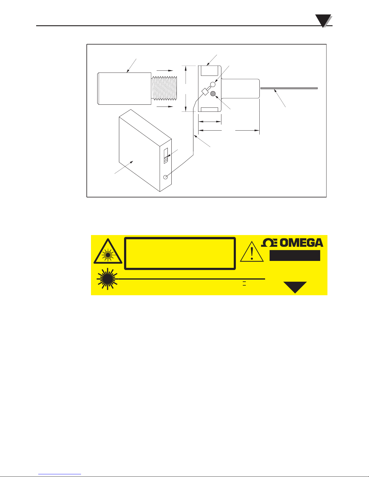
2.3.2 Laser Sighting Accessory Operation
The laser sight accessory screws onto the front of the sensor head. This accessory
is only used for alignment of the sensor head to the target area. After the
alignment process, the accessory has to be removed from the front of the sensor
head before temperature measurement.
The laser sight accessory is powered from a small compact battery pack
(included with the accessory). Connect the battery pack to the accessory using
the cable provided. Aim at the target, and turn on the battery power using the
slide switch on the battery pack. Adjust the sensor head position so that the
laser beam points to the center of the target area. Turn off the battery pack,
and remove the laser sighting accessory from the sensor head. See Fig. 2-5 for
reference.
CAUTION:
You may receive harmful laser radiation exposure if you do not adhere to the
warnings listed below:
• Use of controls or adjustments or performance of procedures other
than those specified here may result in hazardous radiation exposure.
• Do not look at the laser beam coming out of the lens or view directly
with optical instruments - eye damage can result.
• Use extreme caution when operation the laser sight accessory
• Never point the laser accessory at a person
• Keep out of the reach of all children
WARNING:
Do not attempt to open the laser sight accessory. There are no user serviceable
parts inside.
2-4
Page 13
USB Series Probes and Connectors
LED LASER
POWER
INDICATOR
LASER WARNING LABEL
SENSOR HEAD
LASER BEAM
DC POWER JACK
POWER CABLE
SWITCH
ON/OFF
BATTERY PACK
POWER SUPPLY
50.8
(2.0)
19
(.75)
38.1
(1.5 )
Dimensions mm (in.)
2
Figure 2-5. Laser Sighting Accessory, OS100-LS
LASER RADIATION DO NOT STARE
INTO BEAM OR VIEW DIRECTLY WITH
OPTICAL INSTRUMENTS. CLASS 2
LASER PRODUCT.
LASER RADIATION - DO NOT STARE INTO BEAM
AVOID EXPOSURE. LASER
RADIATION IS EMITTED
FROM THIS APERTURE.
OUTPUT <1 mW, WAVELENGTH 630-670 nm, CLASS II (2) LASER
PRODUCT. COMPLIES WITH FDA 21CFR 1040.10 & EN60825-1/11.2001
Figure 2-6. Laser Warning Label
TM
CAUTION
2-5
Page 14

3
Software
Section 3 – Software
3.1 Getting Started
The following program files are included on the TRH Central User Software CD
supplied with your unit. These files can be downloaded from the omega.com
website should you misplace your CD.
• TRH Central Measurement and Data Logging Program
• TRH Central Series Manual (pdf format)
3.2 Software Installation Requirements
3.2.1 System Requirements
Your PC should meet the following minimum requirements:
• Pentium Class or higher processor
• Hard Drive Space: 30 meg
• Ram: 256 meg
• 1 Available USB Port
• 1 CD-ROM Drive
• Windows® XP, Vista (32bit or 64bit), or Windows 7 (32bit or 64bit)
Operating System
3.3 Software Installation
Insert the TRH-Central User CD that was included with your unit into the
CD-ROM drive on your PC. Your system should begin the installation process
automatically.
This welcome screen should be visible on your computer screen. To continue
with installing the program click the “Next >” button.
3-1
Figure 3-1. Welcome Screen
Page 15

Software
This “Install Options” screen should be visible on your computer. To continue
with installing the program check both boxes shown and click the “Next >”
button.
3
Figure 3-2. Install Options Screen
From this screen you select the folder were you want the program files installed
on your PC. The default setting will install the software under your “Program”
folders in a new folder named “Omega” To continue with installing the program
click the “Next >” button.
Figure 3-3. Select Install Folder Screen
3-2
Page 16

3
Software
From this screen you must select “Agree” to continue installing your program.
After making your selection click the “Next >” button. The setup wizard will
now install the software.
Figure 3-4. License Agreement Screen
The setup wizard now has all the information to complete the installation of the
software on your PC. To continue with installing the program click the “Next >”
button.
3-3
Figure 3-5. Confirm Installation Screen
Page 17
Software
3
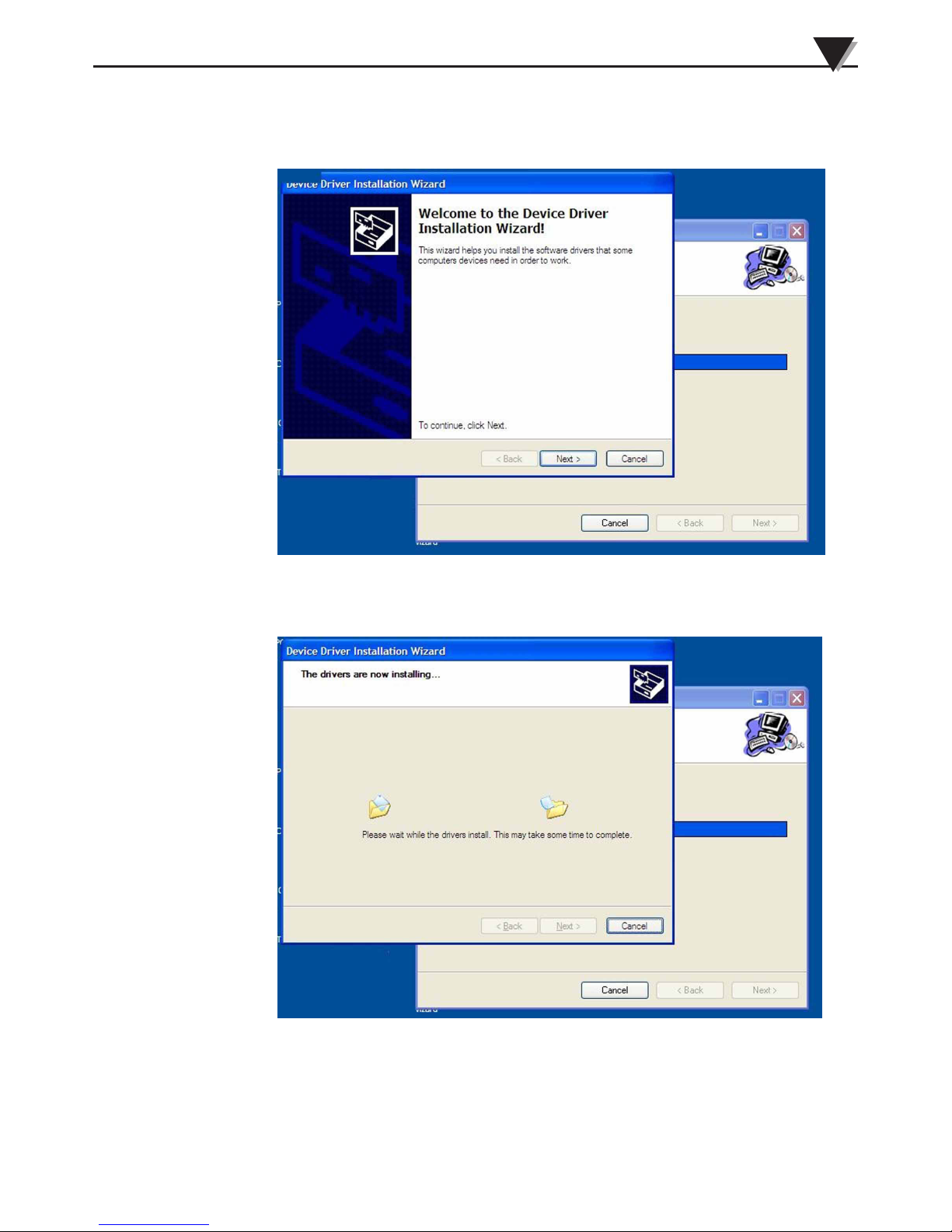
The setup wizard will now install the proper drivers. To continue with installing
the program click the “Next >” button.
Figure 3-6. Welcome to the Device Driver Installation Wizard Screen
Driver installation begins
Figure 3-7. Device Driver Installation Wizard Screen
3-4
Page 18

3
Software
After the installation wizard completes the driver process you should see the
screen below. To finish click the “Finish >” button.
Figure 3-8. Completing the Device Driver Installation Wizard Screen
Congratulations! You have just successfully installed the TRH Central Program
on your PC. To end installing the program and close the setup wizard click the
“Close” button.
3-5
Figure 3-9. Installation Complete Screen
Page 19

3.4 TRH Central Measurement and Recording Program
To launch the TRH Central program on your PC begin by accessing the “All
Programs” list under your “Start Menu” Next, scroll through the list of program
folders to find the “Omega” folder. Inside the “Omega” folder click on the “TRH
Central” program link. This will start the software running.
3.4.1 Main Tab Menu
Channels Tab
The “Channels” tab shown below is the default screen that is displayed when
you run the program. This screen provides a real-time digital reading of relative
humidity (when used with model RH-USB) or pressure in PSI (when used with
model PX409-USB) or temperature (when used with model TJ-USB, UTC-USB,
or IR-USB) in either °F or °C. You can change from °F to °C by clicking with your
pointer the on screen °F or °C buttons.
Software
3
Figure 3-10. Channel Tab Screen
This is a partial view below of the TRH Central Program in operation. This
shows one RH-USB Probe on Channel #1 one TJ-USB Probe on Channel #2, and
one PX409-USB Probe on channel #3, being used at the same time.
Figure 3-11. TRH Central Program Screen
3-6
Page 20

3
Software
3.4.2 Channel Configuration
From the “Tools” pull-down menu select “Configure”….”Channel 1”. This will
open the program settings table were you can make selections on how you want
your system to operate.
Figure 3-12. Channel Configuration Screen
Description Field
In the Description Field you can type a reference name that is associated with the
location or process being measured by the USB device. Example.. “Test Chamber 1”
Low Alarm/High Alarm
When the “High” or “Low” Alarm box is checked the alarm feature becomes
active. Click with your mouse on the “Up” and “Down” buttons to advance to
a higher or lower setting. The displayed temperature reading will change to
RED digits and begin blinking to indicate that the process temperature has gone
below the low alarm or exceeded the high alarm value.
Offset Calibration
This allows you to enter a positive or negative offset to both the process and
ambient readings if needed.
Hide
When the “Hide” box is checked the particular box that you are configuring
will become inactive and will not show up on the screen when running the TRH
Central program. This is used to remove unused boxed when less than 12 units
are being used.
Configure Device
This button opens the dialog box shown on next page (Fig. 3-13).
3-7
Page 21

Software
This box allows you to adjust filter settings to obtain the best balance between
response time and reading stability.
3
3.5 Chart Tab
The “Chart” tab allows you to start, stop and view real-time data from the
transmitters in a screen plot that you can save and print.
Figure 3-13. Device Configuration Screen
Figure 3-14. Charting Screen
3-8
Page 22

3
Software
Start Button
The “Start” button will open the dialog box shown below. This box allows you
to select one or more channels to be plotted. Click the checkbox next to the
channel(s) number you want to include in your plot.
Figure 3-15. Start Data Logging/ Plotting Screen
Line Color
You can change the color specified for each channel’s line. Click the “Change”
button to select a new color for the Channel selected.
Interval
The total logging time is displayed for the interval setting selected. In general,
the interval should normally be set to a value equal to or greater than the same
sample time you programmed into the corresponding connector/transmitter for
that channel.
You can choose to have the data logging/chart recording session end after 1000
data points, or have the session run continuously. After 1000 data points have
been collected in the continuous mode, the oldest data point is shifted out on
the left, and the newest data point is added to the right. Data will continue to be
collected and displayed until you click on the “Stop” button above the chart. If
you click the OK button, the data logging session will start, and “Recording Data”
will flash in the status bar. The “Start” button above the chart will change to
“Stop”, indicating that if you click it again, the logging session will be terminated.
You can also start or stop a data recording session from the File menu. Once
data has been collected, you can save it in a (*.csv) (comma separated values) file
and open it in Microsoft Excel for further analysis. It is recommended that you
“Save As” in Excel as a Microsoft Excel Workbook (*.xls). If you do not modify
the (*.csv) version of the file, you can open it from TRH Central’s File menu, and
display it in the chart and data log.
Clear Button
3-9
The “Clear” button will delete all data from the chart and the data log.
Page 23

Software
3
Configure Axis Button
The “Configure Axis” button allows you to configure both the left and right Y
axis on your chart. The Y Axis Min and Y Axis Max controls allow you to adjust
the viewable range of values to suit your particular application. The narrower
the range between min and max, the more detail can be seen on the chart.
Figure 3-16. Configure Axis Screen
C or F Button
The C or F button allows you to change the units of degrees displayed on the
chart, and on the data logging.
3.6 Charting Options
You can access all of the charting options that are available by opening the chart
option menu found under the “View” Tab. See below.
Figure 3-17. Charting Options Screen
3-10
Page 24

3
Software
Zoom In/Zoom Out
Allow you to change the size of the chart on the screen. You can also use the
Control-Up Arrow and Control-Down Arrow keys as well.
Default Chart Size
Returns the chart to its normal size (after zooming or panning), and places the
title and legend in their normal positions.
Reset Axes
Reset Axes will effectively cancel the results of a Data Zoom and return the axes
back to their original dimensions, but will not change the size of the chart.
Chart (Mouse) Zoom
Perform the same function as mentioned above, by moving the mouse up or
down, or rolling the mouse wheel.
Data (Box) Zoom
When checked, you can use the mouse to click and drag a rectangle around a
line of data to magnify that portion of the chart. The chart size will remain the
same, but the axes will be expanded as well and the data line(s) to allow viewing
more detail. You can close either of the axis scroll bars by clicking on the Red
button of each scroll bar.
Pan
Allows you to move the chart as well as the title and legend around on the
screen. If the Pan item is checked, you can still use the mouse wheel to zoom in
and out, while holding the left button down to move the chart as
Reset Axes will effectively cancel the results of a Data Zoom and return the axes
back to their original dimensions, but will not change the size of the chart.
Floating Cursor
When checked, will display a crosshair type cursor that you can move with the
mouse. You can use the Floating Cursor to pinpoint a particular temperature
and time. The status bar displays the data point number, the time, and the
temperature, where the crosshairs meet. If the horizontal cursor line is touching
a data plot line, the corresponding channel number is also displayed in the status
bar.
3-11
Page 25

Software
3
Tracking Cursor
When checked, will perform similarly to the Floating Cursor, except that you can
specify a channel for the horizontal cursor line to lock on to. This channel is also
displayed in the status bar. With this option enabled, you can move the mouse
left and right without regard to up and down, and the horizontal cursor will
remain pointing to the line (channel) you specify. Assuming you have more than
one channel plotted on the chart, you can switch tracking to another channel
by moving the mouse over the data line of that channel until the mouse cursor
becomes a hand with a pointing finger. If you left-click at this point, the Tracking
Cursor will track that line. You can also change the channel of the Tracking
Cursor from the chart’s context menu, Tracking Cursor menu item combo box.
The same option is also available in the View Chart menu in the main menu bar
Line Options
Allows you to select which channel(s) you want to display, and/or change the
color of each channel data line. This allows you to limit your view to either a
single channel, or a selected two or more channels for comparison, instead of
having all twelve channels displayed at once.
3.6 Data Log Tab
Data Log Tab
The “Data Log” tab allows you to view received data in a table format of any
data as it is being recorded, or data retrieved from a file. The Start and Clear
button perform the same function as the Start and Clear buttons on the Chart
Tab. See Chart Tab above. The adjust button resizes the columns to the smallest
size necessary to fit the data in the columns. You can also change the engineering
units of the data from C to F using the C/F buttons. The Auto Scroll Rows
checkbox causes the data to be scrolled up one line each time a new row of data
is added to the grid.
Figure 3-18. Data Log TAB Screen
3-12
Page 26

3
Software
Figure 3-19. Data Logging Screen
Start Button
The “Start” button will open the dialog box shown below. This box allows you
to select one or more channels to be plotted. Click the checkbox next to the
channel(s) number you want to include in your plot.
3-13
Figure 3-20. Start Data Logging/Plotting Screen
Page 27

Software
3
Menus
File Menu
The Open menu item displays a dialog box which allows you to choose a data
file to open and display on the graph and in the data log. This file must be a
file that was saved by the Save menu item in TRH Central. If the file has been
modified externally, you may not be able to open it.
The Save menu item displays a dialog box which allows you to save the data
currently displayed on the graph and in the data log. The file format is (*.csv)
(comma separated values), which can be opened by Microsoft Excel for further
analysis and charting. It is strongly recommended that you do not modify this
file, or you may not be able to open it again in USB-Temp. Use Excel’s “Save
As” option to save it as a Microsoft Excel Workbook (*.xls), which you can then
modify.
The Export Graph menu item displays a dialog box that allows you to either
save an image of the current graph on the Graph Tab, or copy it to the clipboard.
The Print Preview menu item displays a standard Windows Print Preview
dialog, allowing you to view the item(s) as they would be printed on a printer.
You can also print from this dialog by clicking the printer icon in the upper left
corner. If the Graph Tab is displayed before choosing this option, the current
graph image will be previewed. If the Data Acquisition Tab is displayed, the
data table in grid style format will be previewed.
The Print menu item displays a standard Windows Print dialog box. This allows
you to select printers, printer preferences, page ranges, number of copies, etc.
If you click the “Print” button, the specified page(s) will be sent to the printer.
If you click the “Apply” button, you can then select the Print Preview menu to
view your changes without printing.
The Exit menu option exits the TRH Central program.
View Menu
The Show Toolbar menu allows you to display an optional toolbar for file open,
save, print, and graph positioning.
The Show Most Recently Used menu option displays the most recently used
(opened/saved) filenames in the File menu.
The Clear Most Recently Used menu option removes all recently used filenames
from the File menu.
Graph Menu
Graph Tools Cursor
Floating Cursor, when checked, will display a crosshair type cursor that you can
move with the mouse. You can use the Floating Cursor to pinpoint a particular
temperature and time. The status bar displays the data point number, the time,
and the temperature, where the crosshairs meet.
Tracking Cursor, when checked, will perform similarly to the Floating Cursor,
except that it will lock on to the plot line. With this option enabled, you
can move the mouse left and right without regard to up and down, and the
horizontal cursor will remain pointing to the plot line.
3-14
Page 28

3
Software
Data (Box) Zoom, when checked, allows you to use the mouse to click and drag
a rectangle around a line of data to magnify that portion of the chart. The chart
size will remain the same, but the axes will be expanded as well and the data
line(s) to allow viewing more detail. Click and drag the left mouse button to the
right and downwards. A bluish translucent rectangle will appear showing the
area that will be displayed when the mouse button is released. Note that moving
the mouse in the opposite direction Zooms Out. To cancel data zoom select
“Reset Axes” from either the context menu or Graph menu options.
Zoom allows you to change the overall zoom factor of the chart. This is achieved
by clicking the left mouse button anywhere on the chart and dragging the
mouse. Dragging the mouse toward the bottom of the chart area zooms out
while dragging toward the top zooms in. If you have a wheel mouse you can
zoom in/out by clicking on the chart then use the wheel to zoom in/out.
Configure
The Configure Axes menu allows you to adjust the viewable range of
temperatures to suit your particular application. The narrower the range
between minimum and maximum, the more detail can be seen on the chart.
The Graph Area menu allows you to change the color and/or style of the chart
background, lines and markers.
The Show Gridlines option displays or hides gridlines on the graph.
The Show Markers option displays or hides data point markers on the plotted
data line.
Cancel Zoom will cancel and uncheck Data (Box Zoom) or Zoom if either is
enabled.
Reset Axes returns the graph to its original size.
Data Menu
The Auto Fit Columns menu option resizes the columns to the smallest size
necessary to fit all the data in the columns.
The Auto Scroll menu option causes the data to be scrolled up one line each time
a new row of data is added to the grid.
3-15
Page 29

Section 4 – Specifications
Model TJ-USB Temperature Probe
Integral Thermocouple: Type- K (ungrounded)
Measurement Range: K1: -73 to 315°C (-100 to 600°F)
Accuracy
K1: ±1°C (1.8°F)
K2: ±3°C (5.4°F)
Resolution: USB-TC-K1: 0.1°; USB-TC-K2: 1°
Stability: USB-TC-K1: ±0.25°C, USB-TC-K2: ±0.5°C
Cold Junction Compensation
(Automatic): -10 to 70°C
Operating Environment: -10 to 70°C, 0-95% relative humidity (non-
Specifications
K2: -200 to 1000°C (-354 to 1832°F)
NOTE: For 304 stainless steel max temperature
is 850°C (1562°F)
condensing)
4
PC Interface: USB
USB Cable: Integral to probe, (6' shielded) Type A.
Software (Included): Requires Windows® XP, Vista (32bit or 64bit),
or Windows 7 (32bit or 64bit) operating system
Weight: 70 g (2.5 oz)
4-1
Page 30

4
Specifications
Section 4 – Specifications cont’d.
Model UTC-USB Universal Thermocouple Connector/Converter
User Selectable:
J, K, T, E, R, S, B, C or N Thermocouple Measurement Range:
J: -100 to 760°C (-148 to 1400°F)
K: -100 to 1260°C (-148 to 2300°F)
T: -200 to 400°C (-328 to 752°F)
E: -200 to 1000°C (-328 to 1832°F)
R: 260 to 1760°C (500 to 3200°F)
S: 260 to 1760°C (500 to 3200°F)
B: 870 to 1820°C (1598 to 3308°F)
C: 0 to 2315°C (32 to 4200°F)
N: -100 to 1260°C (-148 to 2300°F)
Measurement Accuracy:
Type J, K: ±0.5% of reading or ±1.0°C(1.8°F),
whichever is greater
Type T, E, N: ±0.5% of reading or ±2.0°C(3.6°F),
whichever is greater
Type R, S, B, C: ±0.5% of full scale
Measurement Resolution: 1°C
Cold Junction Compensation
(Automatic): -10 to 70°C (14 to 158°F)
Thermocouple Connection: Patented universal female accepts both
standard or miniature male connector
Operating Environment: -10 to 70°C (14 to 158°F)
Computer Interface: USB (one interface cable included with
receiver)
Software (Included Free): Requires Windows® XP, Vista (32bit or 64bit),
or Windows 7 (32bit or 64bit) operating system
Dimensions: 76 L x 25.4 W x 13 H mm (3 x 1 x 0.5")
Enclosure: Plastic (Glass Filled Nylon)
4-2
Page 31

Section 4 – Specifications cont’d.
Model PX409-USB Pressure Transducer
Accuracy: 0.08% Best Straight Line (linearity, hysteresis
Temperature Compensation
Over Compensated Range: Span: 0.5%
Zero: 0.5%
Minimum Isolation Between: Case and Output Terminations:
Pressure Cycles: 1 million, minimum
Long Term Stability (1-Year): ±0.1% FS typical
A to D Conversion: 14-Bit
Shock: 50g, 11 mS half sine shock, (under test)
Vibration: ±20g (under test)
Bandwidth: DC to 100 Hz typical
and repeatability combined)
100 MΩ @ 50 Vdc
Specifications
4
CE Compliant: Meets industrial emissions and immunity
standard IEC61326 (pending)
Environmental Protection: IP65 or IP67 depending upon electrical
termination
Secondary Containment
Vacuum and Pressure: 10 inH2O to 5 psi: to 1000 psi
15 to 1000 psi: to 3000 psi
1500 to 5000 psi: to 15,000 psi
Secondary Containment
Absolute Pressure: 5 to 1000 psi: to 6000 psi
1500 to 5000 psi: to 15,000 psi
Wetted Parts: 316L SS
Weight: 200 g (7 oz)
Overpressure Gage Pressure: 10 inH2O: 10 times span
1 psi: 6 times span
2.5 psi to 3500 psi: 4 times span
5000 psi: 15,000 psi max
Overpressure Absolute Pressure: 5 psia: 6 times span
15 psia to 3500 psia: 4 times span
5000 psia: 15000 psi max
Operating Temperature Range: -40 to 85°C (-40 to 185°F)
Compensated Temperature: Ranges >5 psi: -29 to 85°C (-20 to 185°F)
Ranges ≤5 psi: -17 to 85°C (0 to 185°F)
Dimensions: PX409 USB Ranges up to 1000 PSIG, 4.4 L
PX409 USB Ranges above 1000 PSIG, 5.0 L
0.88 Dia.
Enclosure: 3/16 L Stainless Steel
4-3
Page 32

4
Specifications
Section 4 – Specifications cont’d.
Model RH-USB Humidity Probe
Temperature
Range: -17 to 49ºC (1 to 120ºF)
Accuracy: ±1ºC (±1.8°F)
Relative Humidity
Range: 2 to 98% RH
Accuracy: ±3% RH (@ 15 to 90% RH)
Repeatability: ±1% RH
PC Interface: USB
USB Cable: Integral to sensor,
Software (Included): Requires Windows® XP, Vista (32bit or 64bit),
Housing: 316 stainless steel
2 m (6') (shielded) Type A plug
or Windows 7 (32bit or 64bit) operating system
Dimensions: 138 L x 16 mm D (5.5 x 0.625")
Weight: 67 g (0.18 lbs)
4-4
Page 33

Section 4 – Specifications cont’d.
Model IR-USB and IR-USB-HT Infrared Sensor
PC Interface: USB
USB Cable: Integral to sensor, 2 m (6') shielded Type A
Software (Included): Requires Windows® XP, Vista (32bit or 64bit),
Temperature Range: -18 to 538°C (0 to 1000°F)
Accuracy @ 22°C (72°F) Ambient
Temperature and Emissivity of
0.95 or Greater: ±2% rdg or 2.2°C (4°F), whichever is greater
Optical Field of View: 6:1 (distance/spot size)
Repeatability: ±1% rdg
Spectral Response: 5 to 14 microns
Response Time: 100 ms (0 to 63% of final value)
Specifications
4
plug
or Windows 7 (32bit or 64bit) operating system
Emissivity Range: 0.1 to 1.00, adjustable
Operating Temperature
Sensor Head: 0 to 70°C (32 to 158°F)
Sensor Head (-HT Model): 0 to 85°C (32 to 185°F)
Sensor Head with OS100-WC
(Water Cooling Jacket): 0 to 200°C (32 to 392°F)
Operating Relative Humidity: Less than 95% RH, non-condensing
Water Flow Rate (OS100-WC): 0.25 GPM, room temperature
Thermal Shock: ˜30 minutes for 25°C (77°F) abrupt ambient
temperature change
Warm-Up Period: 3 minutes
Air Flow Rate (OS100-AP): 1 CFM (0.5 L/s) (1 x 2.5")
4-5
Page 34

5
IR-USB Emissivity Table
Section 4 – Specifications cont’d.
Laser Sight Accessory (OS100-LS)
Wavelength (Color): 630 - 670 nm (Red)
Operating Distance (Laser Dot): Up to 9.1 m (30 ft.)
Max. Output Optical Power: Less than 1 mW at 22°F ambient
European Classification: Class 2, EN60825-1/11.2001
Maximum Operating Current: 45 mA at 3 Vdc
FDA Classification: Complies with 21 CFR 1040.10,
Beam Diameter: 5 mm
Beam Divergence: < 2 mrad
Operating Temperature: 0 to 50°C (32 to 122°F)
Operating Relative Humidity: Less than 95% RH, non-condensing
temperature.
Class II Laser Product
Power Switch: ON/OFF , Slide switch on the Battery
Pack
Power Indicator: Red LED
Power: Battery Pack, 3 Vdc (Consists of two 1.5
Vdc AA size Lithium Batteries)
Laser Warning Label: Located on the head sight circumference
Identification Label: Located on the head sight circumference
Dimensions: 38 DIA x 50.8 mm L (1.5" DIA x 2" L)
Figure 4-1. Optical Fielf of View
DISTANCE: SENSOR TO OBJECT (IN)
0"
SPOT DIA.* (IN)
0.4"@0"
1cm@0
SPOT DIA.* (CM)
0
* SPOT DIAMETER MEASURED AT 90% ENERGY
12" 6"
2.0"
1.0"
3.3
20
6.6
40
DISTANCE: SENSOR TO OBJECT (CM)
24"
4.0"
D:S=6:1
10.0
60
13.0
80
36"
6.0"
16.0
100
48"
8.0"
20.0
122
Optical Field of View
4-6
Page 35

Section 5 - Emissivity Table (For IR-USB Models)
Material Emissivity (ε)
Aluminum – pure highly polished plate . . . . . . . . . . . . . . . . . . . . . . . . . . . . . . 0.04 to 0.06
Aluminum – heavily oxidized ..................................... 0.20 to 0.31
Aluminum – commercial sheet ........................................... 0.09
Brass – dull plate ..................................................... 0.22
Brass – highly polished, 73.2% Cu, 26.7% Zn .............................. 0.03
Chromium – polished............................................ 0.08 to 0.36
Copper – polished .................................................... 0.05
Copper – heated at 600°C (1112°F) ..................................... 0.57
Gold – pure, highly polished or liquid............................... 0.02 to 0.04
Iron and steel (excluding stainless) – polished iron ..................... 0.14 to 0.38
Iron and steel (excluding stainless) – polished cast iron ....................... 0.21
Iron and steel (excluding stainless) – polished wrought iron .................... 0.28
Iron and steel (excluding stainless) – oxidized dull wrought iron ................ 0.94
Iron and steel (excluding stainless) – rusted iron plate ........................ 0.69
Iron and steel (excluding stainless) – polished steel .......................... 0.07
Iron and steel (excluding stainless) – polished steel oxidized at
600°C (1112°F) ........................... 0.79
Iron and steel (excluding stainless) – rolled sheet steel ........................ 0.66
METALS
Iron and steel (excluding stainless) – rough steel plate .................. 0.94 to 0.97
Lead – gray and oxidized .............................................. 0.28
Mercury ..................................................... 0.09 to 0.12
Molybdenum filament ........................................... 0.10 to 0.20
Nickel – polished..................................................... 0.07
Nickel – oxidized at 649 to 1254°C (1200°F to 2290°F) ............... 0.59 to 0.86
Platinum – pure polished plate .................................... 0.05 to 0.10
Platinum – wire ............................................... 0.07 to 0.18
Silver – pure and polished........................................ 0.02 to 0.03
Stainless steel – polished ............................................... 0.07
Stainless steel – Type 301 at 232 to 942°C (450°F to 1725°F) .......... 0.54 to 0.63
Tin – bright.......................................................... 0.06
Tungsten – filament ................................................... 0.39
Zinc – polished commercial pure......................................... 0.05
Zinc – galvanized sheet................................................ 0.23
Emissivity Table
5
5-1
Page 36

5
Emissivity Table
Material Emissivity (ε)
Asbestos Board ....................................................... 0.96
Asphalt, tar, pitch ............................................... 0.95 to 1.00
Brick – red and rough .................................................. 0.93
Brick – fireclay ....................................................... 0.75
Carbon – filament ..................................................... 0.53
Carbon – lampblack - rough deposit ................................ 0.78 to 0.84
Glass - Pyrex, lead, soda ......................................... 0.85 to 0.95
Marble – polished light gray ............................................ 0.93
Paints, lacquers, and varnishes – Black matte shellac .......................... 0.91
Paints, lacquers, and varnishes – aluminum paints ...................... 0.27 to 0.67
Paints, lacquers, and varnishes – flat black lacquer ..................... 0.96 to 0.98
NONMETALS
Paints, lacquers, and varnishes – white enamel varnish ........................ 0.91
Porcelain – glazed .................................................... 0.92
Quartz – opaque ............................................... 0.68 to 0.92
Roofing Paper ........................................................ 0.91
Tape – Masking ...................................................... 0.95
Water ........................................................ 0.95 to 0.96
Wood – planed oak ................................................... 0.90
5-2
Page 37

NOTES:
USB Series Probes, Sensors, Connectors, and Pressure Transducers
5-3
Page 38

USB Series Probes, Sensors, Connectors, and Pressure Transducers
NOTES:
5-4
Page 39

WARRANTY/DISCLAIMER
OMEGA ENGINEERING, INC. warrants this unit to be free of defects in materials and workmanship for a
period of 13 months from date of purchase. OMEGA’s WARRANTY adds an additional one (1) month grace
period to the normal one (1) year product warranty to cover handling and shipping time. This ensures
that OMEGA’s customers receive maximum coverage on each product.
If the unit malfunctions, it must be returned to the factory for evaluation. OMEGA’s Customer Service
Department will issue an Authorized Return (AR) number immediately upon phone or written request.
Upon examination by OMEGA, if the unit is found to be defective, it will be repaired or replaced at no
charge. OMEGA’s WARRANTY does not apply to defects resulting from any action of the purchaser,
including but not limited to mishandling, improper interfacing, operation outside of design limits,
improper repair, or unauthorized modification. This WARRANTY is VOID if the unit shows evidence of
having been tampered with or shows evidence of having been damaged as a result of excessive corrosion;
or current, heat, moisture or vibration; improper specification; misapplication; misuse or other operating
conditions outside of OMEGA’s control. Components in which wear is not warranted, include but are not
limited to contact points, fuses, and triacs.
OMEGA is pleased to offer suggestions on the use of its various products. However,
OMEGA neither assumes responsibility for any omissions or errors nor assumes liability for
any damages that result from the use of its products in accordance with information provided
by OMEGA, either verbal or written. OMEGA warrants only that the parts manufactured by the
company will be as specified and free of defects. OMEGA MAKES NO OTHER WARRANTIES OR
REPRESENTATIONS OF ANY KIND WHATSOEVER, EXPRESSED OR IMPLIED, EXCEPT THAT OF
TITLE, AND ALL IMPLIED WARRANTIES INCLUDING ANY WARRANTY OF MERCHANTABILITY
AND FITNESS FOR A PARTICULAR PURPOSE ARE HEREBY DISCLAIMED. LIMITATION OF
LIABILITY: The remedies of purchaser set forth herein are exclusive, and the total liability of
OMEGA with respect to this order, whether based on contract, warranty, negligence,
indemnification, strict liability or otherwise, shall not exceed the purchase price of the
component upon which liability is based. In no event shall OMEGA be liable for
consequential, incidental or special damages.
CONDITIONS: Equipment sold by OMEGA is not intended to be used, nor shall it be used: (1) as a “Basic
Component” under 10 CFR 21 (NRC), used in or with any nuclear installation or activity; or (2) in medical
applications or used on humans. Should any Product(s) be used in or with any nuclear installation or
activity, medical application, used on humans, or misused in any way, OMEGA assumes no responsibility
as set forth in our basic WARRANTY/DISCLAIMER language, and, additionally, purchaser will indemnify
OMEGA and hold OMEGA harmless from any liability or damage whatsoever arising out of the use of the
Product(s) in such a manner.
RETURN REQUESTS/INQUIRIES
Direct all warranty and repair requests/inquiries to the OMEGA Customer Service Department. BEFORE
RETURNING ANY PRODUCT(S) TO OMEGA, PURCHASER MUST OBTAIN AN AUTHORIZED RETURN (AR)
NUMBER FROM OMEGA’S CUSTOMER SERVICE DEPARTMENT (IN ORDER TO AVOID PROCESSING
DELAYS). The assigned AR number should then be marked on the outside of the return package and on any
correspondence.
The purchaser is responsible for shipping charges, freight, insurance and proper packaging to prevent
breakage in transit.
FOR WARRANTY RETURNS, please have the
following information available BEFORE contacting
OMEGA:
1. Purchase Order number under which the product
was PURCHASED,
2. Model and serial number of the product under
warranty, and
3. Repair instructions and/or specific problems
relative to the product.
OMEGA’s policy is to make running changes, not model changes, whenever an improvement is possible. This affords our
customers the latest in technology and engineering.
OMEGA is a trademark of OMEGA ENGINEERING, INC.
© Copyright 2018 OMEGA ENGINEERING, INC. All rights reserved. This document may not be copied, photocopied,
reproduced, translated, or reduced to any electronic medium or machine-readable form, in whole or in part, without the prior
written consent of OMEGA ENGINEERING, INC.
FOR NON-WARRANTY REPAIRS, consult
OMEGA for current repair charges. Have
the following information available BEFORE
contacting OMEGA:
1. Purchase Order number to cover the COST
of the repair,
2. Model and serial number of the product, and
3. Repair instructions and/or specific problems
relative to the product.
Page 40

Where Do I Find Everything I Need for
Process Measurement and Control?
OMEGA…Of Course!
Shop online at omega.com
TEMPERATURE
MU
Thermocouple, RTD & Thermistor Probes, Connectors,
Panels & Assemblies
MU
Wire: Thermocouple, RTD & Thermistor
MU
Calibrators & Ice Point References
MU
Recorders, Controllers & Process Monitors
MU
Infrared Pyrometers
PRESSURE, STRAIN AND FORCE
MU
Transducers & Strain Gages
MU
Load Cells & Pressure Gages
MU
Displacement Transducers
MU
Instrumentation & Accessories
FLOW/LEVEL
MU
Rotameters, Gas Mass Flowmeters & Flow Computers
MU
Air Velocity Indicators
MU
Turbine/Paddlewheel Systems
MU
Totalizers & Batch Controllers
pH/CONDUCTIVITY
MU
pH Electrodes, Testers & Accessories
MU
Benchtop/Laboratory Meters
MU
Controllers, Calibrators, Simulators & Pumps
MU
Industrial pH & Conductivity Equipment
DATA ACQUISITION
MU
Communications-Based Acquisition Systems
MU
Data Logging Systems
MU
Wireless Sensors, Transmitters, & Receivers
MU
Signal Conditioners
MU
Data Acquisition Software
HEATERS
MU
Heating Cable
MU
Cartridge & Strip Heaters
MU
Immersion & Band Heaters
MU
Flexible Heaters
MU
Laboratory Heaters
ENVIRONMENTAL
MONITORING AND CONTROL
MU
Metering & Control Instrumentation
MU
Refractometers
MU
Pumps & Tubing
MU
Air, Soil & Water Monitors
MU
Industrial Water & Wastewater Treatment
MU
pH, Conductivity & Dissolved Oxygen Instruments
M4707/0418
 Loading...