Remove the Packing List and verify that you have received all equipment, including the following(quantities in parentheses):
RG-2500 Tipping Bucket Rain Gauge (1)Operator’s Manual (1)If you have any questions about the shipment, please call the OMEGA Customer Service
Department.When you receive the shipment, inspect the container and equipment for signs of damage. Note
any evidence of rough handling in transit. Immediately report any damage to the shipping agent.
The carrier will not honor damage claims unless all shipping material is saved for
inspection. After examining and removing contents, save packing material and
carton in the event reshipment is necessary.
Page 5
Y
Page 6
TABLE OF CONTENTS
Chapter 1 Introduction
1.1 General Description
1.2 Specifications
Chapter 2 Installation
2.1 Site Requirements
2.2 Installation
Chapter 3 Operation
Chapter 4 Calibration
4.1 Factory Calibration
4.2 Calibration Procedure
4.3 Field Calibration
4.4 Adjustments
..........................................
..................
........................................
..........................................
.....................................
..........................................
..........................................
....................................
...................................
......................................
.........................................
Chapter 5 Maintenance
Chapter 6 Troubleshooting
1
.................
‘.
11
222
.
3
......,,...................,..............
33344
.
6
........................................
. 6........,....,........................
Page 7
.
Chapter 1: Introduction
1.1 General Description
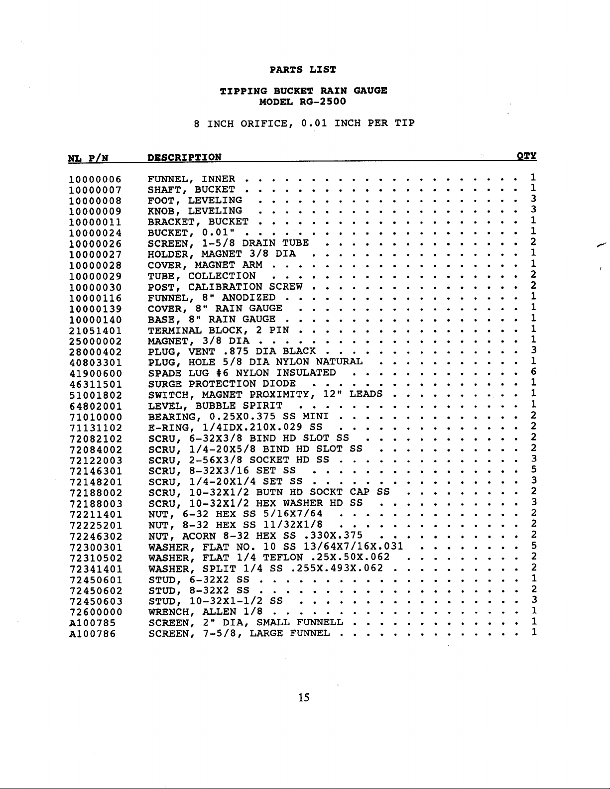
The RG-2500 Series consists of two high quality rain gauges, Models RG-2500 and
RG-2500-12. Model RG-2500 features a standard eight-inch diameter orifice, while the ModelRG-2500-12 has a twelve-inch diameter orifice. Both gauges have been designed with high
grade materials and have been built to provide years of trouble-free operation.
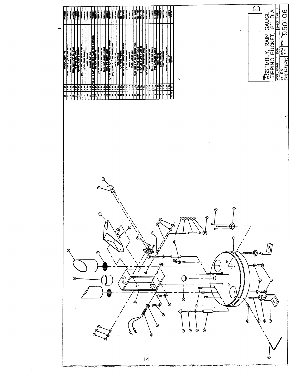
Each of the two gauges consists of a main collection funnel, an outer cover, an internalfunnel, a tipping bucket and magnetic switch assembly, a base, and mounting feet withleveling adjustments.
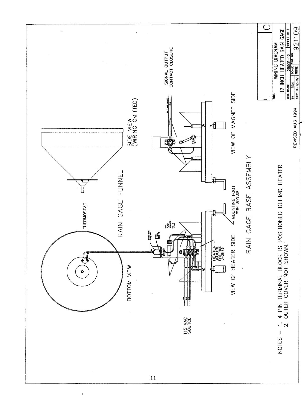
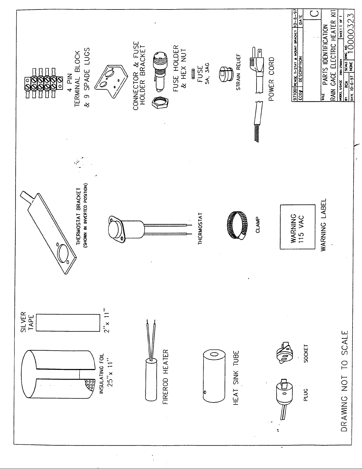
Electrically heated versions of both gauges can be provided for use in cold climates, for
measuring frozen precipitation such as snow and sleet. The electrically heated versionsinclude the features listed above plus a heater element, a thermostat, a fuse holder and fuse,
and associated wiring and terminal blocks. The model numbers for the heated rain gauges areRG-2500E and
RG-2500E-12.
1.2 Specifications
Capacity:
Unlimited
Orifice:
RG-2500: 8” (20 cm)RG-2500-12: 12” (30 cm)
Calibration: Accuracy:
Switch:
0.01” per tip (0.25 mm), others on request+
+
1% for 1 to 3 inches per hour,
3% for 0 to 6 inches per hour
Magnetic reed, SPST N.O., 10 Watts, 200 Vdc, 0.5 A max
Dimensions:
8”
RG-2500:
x 17”
RG-2500-12: 12” x 20”
Weight/Shipping:
RG-2500: 7RG-2500-12: 14
lbs/12 lbs
lbs/18 lbs
Optional Accessories:
Wind Screen, Alter TypeEvent Recorder, Drum ChartCalibrator BottleDigital Event Counter
Model RG-952Model RG-6113-AModel RG-2595Model RG-2596
1
Page 8
Chapter 2: Installation
2.1 Site Requirements
The location of the rain gauge is very important to the successful operation of the instrument.
The most accurate measurements are made in relatively sheltered areas protected fromgusting and turbulent winds. Openings in orchards or a grove of trees offer the best exposurefor the rain gauge. Fences and other structures can help serve as a wind break as long as
they are not too tall. In areas that are open with no nearby structures, a wind screen such is
recommended to protect against wind effects.
Generally, the heights of objects near a rain gauge should be proportional to the distance
away from the gauge. The distance of a nearby object should always be at least twice theheight of the object above the gauge.
Wind effects on catch losses are more pronounced during snow storms than during a rainstorm. A wind screen is generally not used at locations where snowfall constitutes less than20% of the mean annual precipitation.
Good locations do not always remain free of obstructions. Vegetation can grow quickly,changing an excellent exposure into a poor one. Sites should be inspected regularly in orderto properly maintain the exposure of the gauge.
In locations with heavy snowfall, the gauge should be mounted on a support or tower toplace thetower were
gauge well above the average local snow level. The exposure would be best if the
to
be located among trees of the same height as the tower.
2.2 Installation
OMEGA@ rain gauges are shipped as a complete assembly with no additional assemblyrequired. ‘The gauge, however, should be installed onto a platform or foundation that is
fairlyclose to being level to minimize the amount of adjustment required after the gauge ismounted. Each gauge is equipped with three mounting brackets that also serve as feet. Eachfoot has a mounting hole with a diameter of
3/8 inches. The holes in the feet should bematched to anchor bolts located in the foundation or on the platforms. for severely tiltedfoundations, use a set of three hex nuts on each bolt to provide leveling and locking of the
rain gauge onto the foundation. For slightly tilted foundations, use the adjustable leveling
knobs above each foot to level the gauge. An internally mounted spirit level may be used to
assist in the leveling process. A rough level can be taken by placing a carpenter’s level
across the top of the gauge funnel. Flat washers may be used as shims to help correct largeleveling differences. Place the shims under the mounting feet. A lock washer and a hex nutshould be used to secure the gauge onto the anchor bolts. Some correction of the level maybe necessary after tightening the hex nuts.
2
Page 9
The leveling knobs located above the mounting feet are secured using
allen
head set screws.These set screws must be loosened before the knobs can be moved. The set screws areaccessible from the sides of the base. Re-tighten the set screws after leveling the gauge tohelp ensure that the level adjustment will not shift due to loose screws.
The gauge may be installed with the outer cover on or with it removed. Three screws holdthe outer cover in place. Take out these three screws to remove the cover. Carefully removethe cover, avoiding hitting any of the internal rain gauge parts. Some of the moving parts aretied down to prevent movement and possible damage during shipping. Remove any tape,plastic ties, foam inserts, or other objects used to keep the tipping buckets from moving. The
bucket assembly should move easily with the packing materials removed.
Chapter 3: Operation
The rain gauge operation is relatively simple.
As rain is collected by the eight-inch diameterorifice, the rain drops are directed down through the funnel and into the bucket assembly. Assoon as the bucket has collected enough rain to represent 0.01 inches (or 0.25 mm) of rain,
the bucket tips. The rain drains out through the drain collection tubes and the magnet is
moved past the reed switch. The reed switch closes momentarily, making an electricalcontact that is used in conjunction with electronic counting and recording instruments.
Chapter 4: Calibration
4.1 Factory Calibration
Each rain gauge is thoroughly tested before being shipped to the customer. A measuredamount of water is passed through the rain gauge to give an expected number of countsaccording to the diameter of the orifice. The bucket calibration posts have screws that areadjusted until the correct number of counts are achieved with repeated testing. The exact
number of counts or nearly the exact number are recorded for each gauge. As long as thenumber of counts is within the specified accuracy of the gauge, the calibration will be
accepted. The calibration of the gauge should not change during shipping unless the gauge
becomes damaged. Checking of the gauge calibration may be made after the gauge has beeninstalled to ensure the accuracy of the data.
4.2 Calibration Procedure
The rain gauge calibration may be checked using a graduated burette or cylinder. Wet thegauge thoroughly allowing water to flow through the gauge before beginning the test. Thewetting of the gauge helps compensate for water that may adhere to
portions.of the gauge
causing some error in the counts.
3
Page 10
Allow a measured amount of water to flow into the gauge at a specified rate. Refer to thetable shown below. The tipping bucket should begin tipping and will give the number of tipscalculated. The tips may be counted by listening to the bucket assembly and manuallytabulating the count or by using the electronic monitoring equipment that is to be connectedto the rain gauge during its normal operation. Should the gauge appear to need adjustment,make the adjustments in small increments and retest each change at least three times.
Use a flow rate of 1 ml per second to avoid over filling of the buckets and loss of water due
~3%
to splashing. the desired accuracy is
of the volume at 1 to 6 inches of precipitation perhour. Best results are obtained by taking a multiple of the volume of water and counting anumber of tips. For example, the 0.01” calibration at 100 counts requires 824 milliliters of
water.
4.3 Field Calibration
To verify the rain gauge calibration after the gauge has been installed, best results may beobtained using the calibration bottle. The bottle may be filled to the specified level and thenplaced into the funnel of the gauge. While the bottle slowly empties the water into the funnelother tasks may be performed if necessary. If the calibration bottle is not available, use anycalibrated measuring device and slowly pour the water into the gauge. Keep track of thebucket tips either manually or through the use of the electronic monitoring equipment. For
45%
field testing methods, use an expected accuracy of
since the control of the methods isnot as good as when the testing is done in the laboratory. The total number of tips shouldequal the amount of water poured into the gauge, divided by the calibrated number of tipsper the number of milliliters of water shown in the table. For example, a quart of water is
fof
equal to 946.3 milliliters. So for a 0.01” calibration, the number of counts
t
water should be 946.3
8.24 = 114.8.
a quart of
Page 11
4.4
Adjustments
Should the calibration of the rain gauge appear to be incorrect and in need of adjustment,change the heights of the two calibration posts adjustment screws. To change the screwheights, loosen the nut on the top of the post that locks the screw into place. Rotate eachscrew by a small amount only and recheck the calibration for the new screw positions.Empty all water from the buckets but do not dry off the buckets. The exact amount of waterneeded for a single bucket tip may be added into a bucket to see how closely the calibrationpost screw may be to the position needed for the bucket to tip. After obtaining this point ofadjustment, tighten down the locking nuts on the calibration posts screws and test the gaugeusing a large amount of water at the proper flow rate and count the total number of tips.
The calibration post screws should be adjusted upward whenever the amount of water needed
to cause the bucket to tip is more than the amount shown in the calibration table. Wheneverless water than the amount in the table causes the bucket to tip, the screws need to beadjusted downward. The two sides of the bucket assembly should generally be at about thesame calibration adjustment. There may be situations where one of the bucket calibration
post screws has moved and is off more than the other screw. In this situation the single tip
amount of water calibration method may be better for correcting the one side of the bucket tomatch the other side more closely. Do not dry the buckets during the adjustment procedure.
Carefully tighten the locking nuts on the calibration post screws after completing the
adjustments. Recheck the calibration to ensure that the screws have not shifted as the nuts
were tightened.
Chapter 5: Maintenance
Annual maintenance of the rain gauge is recommended. Cleaning of the gauge more oftenmay be necessary in areas where there is a lot of leaves, dust, and other debris that falls intothe gauge. Cleaning includes removal of the outer cover, rinsing and drying off of thebuckets, cleaning of the drain holes, and removal of debris from all of the screens. the outerand inner funnels should also be rinsed and dried off to remove dirt, dust and insects.
The gauge calibration should be tested during the maintenance procedure and adjusted ifnecessary. If there is a regularly scheduled maintenance of the gauge on a monthly basis, thecalibration can be tested less often.
At least once a year, or if possible, after six months of heavy operation, a drop of light
machine oil should be placed onto the bearings. Do not over-oil and wipe off any excess oil.
The electrical output of the gauge should be tested to ensure that the magnet and switchassemblies are still functioning. The switch used in the gauge is a momentary contact,
normally open, single pole switch. Test the switch using an ohmmeter, buzzer, or counter, or
5
Page 12
by observing the data of the monitoring
equipmen
normally connected to the rain gauge.
Manually move the bucket assembly and look for he switch closure.
1
Upon completion of testing and cleaning of the ga
ge,replace the outer cover and funnel andrecheck the level of the gauge using a carpenter’s level across the top of the gauge. Adjustthe leveling knobs at the mounting feet if the level is out of adjustment.
Replace or repair any of the gauge components that appear to be damaged or are notfunctioning properly. The outer funnel should be replaced if the rim has become dented orbent. Repaint the outer cover as needed. Replace any hardware that is missing or has becomerusted and corroded. Inspect the signal and any power cables for signs of wear or damagethat may expose the wires. Replace the cables as needed. Use wire ties to secure the cablesto prevent damage from high winds. For best results, use conduit to protect the cables.
Chapter 6: Troubleshooting
Failure of the rain gauge to operate usually is the result of loose wiring. Inspect the cableconnections to ensure the connections are solid and are correctly made.
Inspect the motion of the bucket assembly to ensure that the buckets move smoothly andwithout any interference. Check the magnet to see that it passes over the switch without anyphysical contact and that the switch closes when the magnet passes over it. Should the bucketmotion appear to be sticky, remove the bearings and inspect them for wear. Annualreplacement of the bearings may be necessary in areas where there are high amounts of rain.
Check the inlet funnel and funnel screens for blockage whenever the rain gauge operationappears to be low or missing. Also inspect the drain tubes for debris that may interfere withthe bucket motion.
Whenever the rain gauge output appears to be too high, check to ensure that the gauge is stilllevel and recheck the calibration.
6
Page 13
r
25 FT CABLE
MODEL 330-0220
(T
YPICAL
)
Z-PIN
TERMINAL
BLOCK
DIODE
MAGNETIC SWITCH
(
NORMALLY
OPEN)
__----
RED
_------
2-PIN
TB
&
w
DIODE
__----
*
BLK
-------
SWITCH
IL7
BLK
N.O.
27 VDCMAXIMUM
3 WATTS
0.25A
@
175 VDC
--
-0MAGNET
MAXIMUM
TYPICAL CLOSURE TIME
0.1 SECOND
NOTES:
1.
TYPICAL OF BOTH HEATED AND UNHEATED RAIN GAUGES.
t
Page 14
25
FT POWER CORD18 AWG, SVT
CASE
GROUND
/ib
4-PIN
TERMINAL
BLOCK
0
1
34
FIRE ROD HEATER400 W
FUSE
5
AMP
SLO BLO
OHMS
@
115 VAC
-
WARN’.ING
115 VAC WILL BE ALIVE ON THE 4-PIN
TERMINAL BLOCK WHENEVER THE POWER
CORD IS PLUGGED INTO A POWER OUTLET.
T!iE
TERMINALS ARE EXPOSED INSIDEGAUGE.
RAIN
\
,
Page 15
8.0”
------I
WTH LEVELER
MOUNTING FEET PATTERN
L(oo.
0.7t:
\
Page 16
2C
5”
0
.
..‘..--.
+
2.0”
t
MOUNTING FOOT
WlTH
LEVELER
MOUNTING FEET PATTERN
us*cE
uoo.
OAIE
-
\
<
Page 17
a
aI=
Page 18
RAIN GAGE FUNNEL
CALIBRATION POST
&
ADJUSTMENT
COLLECTION TUBE
INNER FUNNEL
SCREW\
2 PIN SIGNAL
7
TIPPING BUCKET
MTH
LEVELER
FOOJI~JE
TERMINAL BLOCK
f-
SIGNAL OUTPUT
CONTACT CLOSURE
12 INCH RAIN GAGE BASE ASSEMBLY
OAIE
I
1,
t-o&
Page 19
,/
BOTTOM VIEW
THERMOS
‘TAT
%
RAIN GAGE FUNNEL
\
d_
SIDE VIEW(WIRING OMITTED)
NOTES
-
1. 4
PIN TERMINAL BLOCK IS POSITIONED BEHIND HEATER.
2. OUTER COVER NOT
WlTH
LEMLER
RAIN GAGE BASE ASSEMBLY
SHOWN.’
VIEW OF MAGNET SIDE
REVISED AUG 1994
t
L
nnE
12 INCH HEATED RAIN GAGE
USAef
UOD.
Page 20
PART
722701017234150172317502
7231750272270101
72270101
72500000
NUMBEfiS
5/16
HEX NUT
5/16
LOCK WASHER
5/16
FLAT WASHER
5/16
FLAT WASHER
5/16
HEX NUT
5/16
HEX NUT
5/16
THREADED ROD
MOUNTING BOLT ASSEMBLY DETAIL
g
v
&
RAIN GAGE SECURING NUT
LOCATION OF RAIN GAGE FOOT
HEIGHT ADJUSTING NUTLOCKING NUT
TYPICAL VIEW
7231760272270101
3/8
FLAT WASHER
5/16
HEX NUT
&&
ANCHOR WASHERANCMT
I
FOR INSTALLATIONS
USING A 24” ALTER STYLEWIND SCREEN THIS HEIGHT MUST BE ADJUSTEDSO THAT THE TOP EDGE OF THE RAIN GAGEIS WITHIN 1 INCH OF THE TOP EDGE OF THE
WIND SCREEN LEAVES. SET BOLT HEIGHTPRIOR TO POURING CONCRETE FOUNDATION.
TYPICAL LENGTH OF THREADED ROD WILL BEAPPROXIMATELY 24 INCHES.
SET HEIGHT ADJUSTING NUTS FOR ALL THREE
OF THE RAIN GAGE MOUNTING FEET UNTIL THERAIN GAGE IS LEVEL ACCORDING TO THE SPIRITBUBBLE LEVEL LOCATED ON THE RAIN GAGE BASE.
FOR WOODEN PLATFORMS THEREARE EXTRA NUTS AND WASHERS.
I
nRE
KIT ASSEMBLY ,
By
1
DATE
Page 21
MOUNTING BOLT ASSEMBLY DETAIL
15.25” APPROX
GROUND LEVEL(APPROX)
12”
CONCRETE
FOUNDATION
~
20.75”
!
t
APPROk
I
c
7r
12 INCH
RAIN GAGE
IIII
II
-#Ll
PART NUMBERS
72270101723415017231750272317502
7227010172270101
72500000
7231760272270101
5/16
HEX NUT
5/16
LOCK WASHER
5j16
FLAT WASHER
5/16
FLAT WASHER
5/16
HEXNUT
5/16
HEX NUT
5/16
THREADED ROD
3/8
FLAT WASHER
5/16
HEX NUT
I
RAIN GAGE SECURING NUT
@
&
F
&I
&&
LOCATION OF RAIN GAGE FOOT
HEIGHT ADJUSTING NUTLOCKING NUT
ANCHOR WASHERANCHOR NUT
I
TYPICAL OF THREE EACH
FOR INSTALLATIONS USING A 36” ALTER STYLEWIND SCREEN THIS HEIGHT MUST BE ADJUSTEDSO THAT THE TOP EDGE OF THE RAIN GAGEIS WITHIN 1 INCH OF THE TOP EDGE OF THEWIND SCREEN LEAVES. SET BOLT HEIGHT
PRIOR TO POURING CONCRETE FOUNDATION.TYPICAL LENGTH OF THREADED ROD WILL BE
II
APPROXIMATELY 30 INCHES.SET HEIGHT ADJUSTING
,NUTS
FOR ALL THREEOFTHE RAIN GAGE MOUNTING FEET UNTIL THERAINGAGE IS LEVEL ACCORDING TO THE SPIRITBUBBLE LEVEL LOCATED ON THE RAIN GAGE BASE.
al one (1) month grace period to the normaland shipping time. This ensures that OMEGA’s customers receive maximum coverage on eachproduct. If the unit should malfunction, it must be returned to the factory for evaluation. OMEGA’s
Customer
phone or written request. Upon examination by OMEGA, if the unit is found to be defective it willbe repaired or replaced at no charge. However, this WARRANTY is VOID
of having been tampered with or shows evidence of being damaged as a result of excessive corro-
sion; or current, heat, moisture or vibration; improper specification; misapplication; misuse orother operating conditions outside of OMEGA’s control. Components which wear or which aredamaged by misuse are not warranted. These include contact points, fuses, and
warrants
this unit to be free of defects in materials and workmanship and to give satisfac-
13
months
from date of purchase. OMEGA Warranty adds an addition-
one (1) year product warranty
to cover handling
Service Department will issue an Authorized Return (AR) number immediately upon
if the unit shows evidence
triacs.
OMEGA OMEGA only warrants that the parts manufactured
is glad to offer suggestions on the use of its various products. Nevertheless,
by it will be as specified and free of
defects.
OMEGA MAKES NO
OTHER WARRANTIES OR REPRESENTATIONS OF ANY KIND WHAT-SOEVER, EXPRESSED OR IMPLIED, EXCEPT THAT OF TITLE AND ALL IMPLIED WAR-RANTIES INCLUDING ANY WARRANTY OF MERCHANTABILITY
AND FITNESS
FOR A
PARTICULAR PURPOSE ARE HEREBY DISCLAIMED.LIMITATION OF LIABILITY: The remedies of purchaser set forth herein are exclusive and
the total liability of OMEGA with respect to this order, whether based on contract, war-
ranty, negligence, indemnification, strict liability or otherwise, shall not exceed the
purchase price of the component upon which liability is based. In no event shallOMEGA be liable for consequential, incidental or special damages.
Every precaution for accuracy has been taken in the preparation of this manual; however, OMEGAENGINEERING, INC. neither assumes responsibility
for any omissions or errors that may appear
nor assumes liability for any damages that result from the use of the products in accordance with
the information contained in the manual.SPECIAL CONDITION: Should this equipment be used in or with any nuclear installation or activity,
purchaser will indemnify OMEGA and hold OMEGA harmless from any liability or damage whatso-ever arising out of the use of the equipment in such a manner.
/
RETURN REQUESTS
INQUIRIES
Direct all warranty and repair requests/inquiries to the OMEGA ENGINEERING Customer ServiceDepartment. BEFORE RETURNING
ANY PRODUCT(S) TO OMEGA, PURCHASER MUST OBTAIN AN
AUTHORIZED RETURN (AR) NUMBER FROM OMEGA’S CUSTOMER SERVICE DEPARTMENT (IN
ORDER TO AVOID PROCESSING DELAYS). The assigned AR number should then be marked on theoutside of the return package and on any correspondence.
FOR
FOR
WARRANTY
RETURNS, please have thefollowing information available BEFORE con-tacting OMEGA:
1. P.O. number under which the product wasPURCHASED,
2. Model and serial number of the productunder warranty, and
3. Repair instructions and/or specific prob-lems relative to the product.
OMEGA’s
our customers the latest
OMEGA is a registered trademark of OMEGA ENGINEERING, INC.Q Copyright
reproduced, translated, or reduced to any electronic medium or machine-readable form, in whole or in part, without prior
written consent of OMEGA ENGINEERING, INC.
policy is to make running changes, not model changes, whenever an improvement is possible.
‘I995
in technology and engineering.
OMEGA ENGINEERING, INC. All rights reserved. This documentation may not be copied, photocopied,
NON-WARRANTY
m,
consult OMEGA for current repair/
calibration charges. Have the following infor-
mation available BEFORE contacting OMEGA:
P.0.
1.
number to cover the COST of the
repair/calibration,
2. Model and serial number of product, and
3. Repair instructions and/or specific problemsrelative to the product..


 Loading...