

Page 1

omega.com
e-mail: info@omega.com
For latest product manuals:
omegamanual.info
User’s Guide
RDXL4SD
4-Channel
Datalogger Thermometer
Shop online at
MADE IN TAIWAN
Extended Warranty
Program
SM
Page 2

Servicing North America:
USA: OMEGA Engineering, Inc., One Omega Drive, P.O. Box 4047
ISO 9001 Certified Stamford, CT 06907-0047 USA
Toll-Free: 1-800-826-6342 TEL: (203) 359-1660
FAX: (203) 359-7700 e-mail: info@omega.com
Canada: 976 Bergar
Laval (Quebec), H7L 5A1 Canada
Toll-Free: 1-800-826-6342 TEL: (514) 856-6928
FAX: (514) 856-6886 e-mail: info@omega.ca
For immediate technical or application assistance:
USA and Canada: Sales Service: 1-800-826-6342/1-800-TC-OMEGA
®
Customer Service: 1-800-622-2378/1-800-622-BEST
®
Engineering Service: 1-800-872-9436/1-800-USA-WHEN
®
Mexico/ En Espan˜ol: 001 (203) 359-7803 FAX: 001 (203) 359-7807
Latin America info@omega.com.mx e-mail: espanol@omega.com
Servicing Europe:
Benelux: Managed by the United Kingdom Office
Toll-Free: 0800 099 3344 TEL: +31 20 347 21 21
FAX: +31 20 643 46 43 e-mail: sales@omegaeng.nl
Czech Republic: Frystatska 184
733 01 Karviná, Czech Republic
Toll-Free: 0800-1-66342 TEL: +420-59-6311899
FAX: +420-59-6311114 e-mail: info@omegashop.cz
France: Managed by the United Kingdom Office
Toll-Free: 0800 466 342 TEL: +33 (0) 161 37 29 00
FAX: +33 (0) 130 57 54 27 e-mail: sales@omega.fr
Germany/Austria: Daimlerstrasse 26
D-75392 Deckenpfronn, Germany
Toll-Free: 0800 6397678 TEL: +49 (0) 7056 9398-0
FAX: +49 (0) 7056 9398-29 e-mail: info@omega.de
United Kingdom: OMEGA Engineering Ltd.
ISO 9001 Certified
One Omega Drive
River Bend Technology Centre, Northbank
Irlam, Manchester M44 5BD United Kingdom
Toll-Free: 0800-488-488 TEL: +44 (0) 161 777-6611
FAX: +44 (0) 161 777-6622 e-mail: sales@omega.co.uk
OMEGAnet®Online Service Internet e-mail
omega.com info@omega.com
It is the policy of OMEGA to comply with all worldwide safety and EMC/EMI regulations that
apply. OMEGA is constantly pursuing certification of its products to the European New Approach
Directives. OMEGA will add the CE mark to every appropriate device upon certification.
The information contained in this document is believed to be correct, but OMEGA Engineering, Inc. accepts
no liability for any errors it contains, and reserves the right to alter specifications without notice.
WARNING: These products are not designed for use in, and should not be used for, human applications.
Page 3

TABLE OF
CONTENTS
Section Page
1. Features . . . . . . . . . . . . . . . . . . . . . . . . . . . . . . . . . . . . . . . . . . . . . . . . . . . . . . . 1
2. Specifications . . . . . . . . . . . . . . . . . . . . . . . . . . . . . . . . . . . . . . . . . . . . . . . . . . 2
3. Front Panel Description . . . . . . . . . . . . . . . . . . . . . . . . . . . . . . . . . . . . . . . . . 6
3-1 Display . . . . . . . . . . . . . . . . . . . . . . . . . . . . . . . . . . . . . . . . . . . . . . . . . . . . 6
3-2 Power Button (ESC, Backlight Button) . . . . . . . . . . . . . . . . . . . . . . . . . . 6
3-3 Hold Button (Next Button) . . . . . . . . . . . . . . . . . . . . . . . . . . . . . . . . . . . . 6
3-4 REC Button(Enter Button) . . . . . . . . . . . . . . . . . . . . . . . . . . . . . . . . . . . . . 6
3-5 Type Button (s Button, L Button) . . . . . . . . . . . . . . . . . . . . . . . . . . . . . . 6
3-6 Type Button (t Button, R Button). . . . . . . . . . . . . . . . . . . . . . . . . . . . . . 6
3-7 SET Button (Time Check Button). . . . . . . . . . . . . . . . . . . . . . . . . . . . . . . 6
3-8 Logger Button (OFFSET Button, Sampling Time Check Button . . . . 6
3-9 T1, T2, T3, T4 Input Socket (Type K, Type J). . . . . . . . . . . . . . . . . . . . . 6
3-10 PT1 Input Socket (PT100 Ω). . . . . . . . . . . . . . . . . . . . . . . . . . . . . . . . . . 6
3-11 PT2 Input Socket (PT100 Ω). . . . . . . . . . . . . . . . . . . . . . . . . . . . . . . . . . 6
3-12 RS-232 Output Terminal . . . . . . . . . . . . . . . . . . . . . . . . . . . . . . . . . . . . . 6
3-13 DC9V Adapter Socket . . . . . . . . . . . . . . . . . . . . . . . . . . . . . . . . . . . . . . . 6
3-14 Tripod Fix Nut . . . . . . . . . . . . . . . . . . . . . . . . . . . . . . . . . . . . . . . . . . . . . . 6
3-11 PT2 Input Socket (PT100 Ω). . . . . . . . . . . . . . . . . . . . . . . . . . . . . . . . . . 6
3-12 RS232 Output Terminal . . . . . . . . . . . . . . . . . . . . . . . . . . . . . . . . . . . . . . 6
3-13 DC 9V Adapter Socket . . . . . . . . . . . . . . . . . . . . . . . . . . . . . . . . . . . . . . . 6
3-14 Tripod Fix Nut . . . . . . . . . . . . . . . . . . . . . . . . . . . . . . . . . . . . . . . . . . . . . . 6
3-15 Battery Cover Screws . . . . . . . . . . . . . . . . . . . . . . . . . . . . . . . . . . . . . . . . 6
3-16 Battery Compartment Cover . . . . . . . . . . . . . . . . . . . . . . . . . . . . . . . . . . 6
3-17 Stand . . . . . . . . . . . . . . . . . . . . . . . . . . . . . . . . . . . . . . . . . . . . . . . . . . . . . . 6
3-18 SD Card Socket . . . . . . . . . . . . . . . . . . . . . . . . . . . . . . . . . . . . . . . . . . . . . 6
4. Measuring Procedure . . . . . . . . . . . . . . . . . . . . . . . . . . . . . . . . . . . . . . . . . . . . 7
4-1 Type K Measurement . . . . . . . . . . . . . . . . . . . . . . . . . . . . . . . . . . . . . . . . . 7
4-2 Type J/T/E/R/S Measurement . . . . . . . . . . . . . . . . . . . . . . . . . . . . . . . . . . 7
4-3 PT 100 Ω Measurement . . . . . . . . . . . . . . . . . . . . . . . . . . . . . . . . . . . . . . . 8
4-4 T1-T2 Measurement . . . . . . . . . . . . . . . . . . . . . . . . . . . . . . . . . . . . . . . . . . 8
4-5 Data Hold . . . . . . . . . . . . . . . . . . . . . . . . . . . . . . . . . . . . . . . . . . . . . . . . . . . 9
4-6 Data Record (Max/Min Reading. . . . . . . . . . . . . . . . . . . . . . . . . . . . . . . . 9
4-7 LCD Backlight ON/OFF. . . . . . . . . . . . . . . . . . . . . . . . . . . . . . . . . . . . . . 10
5. Datalogger. . . . . . . . . . . . . . . . . . . . . . . . . . . . . . . . . . . . . . . . . . . . . . . . . . . . . 10
5-1 Preparation Before Execute Datalogger Function . . . . . . . . . . . . . . . . 10
5-2 Auto Datalogger (Set Sampling Time ≥ 1 Sec) . . . . . . . . . . . . . . . . . . 11
5-3 Manual Datalogger (Set Sampling Time = 0 Sec). . . . . . . . . . . . . . . . 12
5-4 Auto Datalogger (Set Sampling Time = 0 Sec) . . . . . . . . . . . . . . . . . . 12
5-5 Check Sampling Time Information. . . . . . . . . . . . . . . . . . . . . . . . . . . . 13
5-6 SD Card Data Structure . . . . . . . . . . . . . . . . . . . . . . . . . . . . . . . . . . . . . . 13
6. Saving Data from the SD Card to the Computer. . . . . . . . . . . . . . . . . . . . 14
7. Advanced Setting. . . . . . . . . . . . . . . . . . . . . . . . . . . . . . . . . . . . . . . . . . . . . . . 15
7-1 Set Clock Time (Year/Month/Date, Hour/Minute/Second). . . . . . . . 16
7-2 Decimal Point of SD Card Setting . . . . . . . . . . . . . . . . . . . . . . . . . . . . . 17
7-3 Auto Power OFF Management . . . . . . . . . . . . . . . . . . . . . . . . . . . . . . . . 17
7-4 Set Beeper Sound ON/OFF . . . . . . . . . . . . . . . . . . . . . . . . . . . . . . . . . . . 18
7-5 Select the Temperature Unit to °C or °F . . . . . . . . . . . . . . . . . . . . . . . . 18
7-6 Set Sampling Time . . . . . . . . . . . . . . . . . . . . . . . . . . . . . . . . . . . . . . . . . . 19
7-7 SD Memory Card Format. . . . . . . . . . . . . . . . . . . . . . . . . . . . . . . . . . . . . 19
8. Power Supply from DC Adapter . . . . . . . . . . . . . . . . . . . . . . . . . . . . . . . . . 20
9. Battery Replacement . . . . . . . . . . . . . . . . . . . . . . . . . . . . . . . . . . . . . . . . . . . . 20
10. RS232 PC Serial Interface. . . . . . . . . . . . . . . . . . . . . . . . . . . . . . . . . . . . . . . 20
11. Offset Adjustment. . . . . . . . . . . . . . . . . . . . . . . . . . . . . . . . . . . . . . . . . . . . . 22
Page 4

1. FEATURES
• Type K/J/T/E/R/S, Pt 100 ohm, measurement with 4 channel display.
• Simultaneously shows 4 channel display on the LCD.
• Type K : -100 to 1300 °C.
• Type J : -100 to 1200 °C.
• Pt 100 ohm : -199.9 to 850.0 °C.
• °C/°F, 0.1 degree/1 degree.
• 4 channels ( T1, T2, T3, T4 ), T1-T2.
• Microcomputer circuit provides intelligent function
and high accuracy.
• Offset adjustment for the Type K/J/T/E/R/S measurement.
• Offset adjustment for the Pt 100 measurement.
• Measuring unit can select to or .
• Real time SD memory card Datalogger, Built-in Clock
and Calendar, real time data recorder, sampling time set
from 1 second to 3600 seconds.
• Manual datalogger is available (set the sampling
time to 0 second), during execute the manual datalogger
function, can be set at different positions (location)
(position 1 to position 99).
• Easy operation, computer is not needed to
setup with software; After execute datalogger just take
the SD card from the meter and plug in the SD card
into a computer. It will down load all the measured
values with the time information ( year/month/date/
hour/minute/second ) to Excel directly; then the user can
make further data or graphic analysis.
• SD card capacity : 1 GB to 16 GB.
• LCD with green light backlight, easy reading.
• Can default auto power off or manual power off.
• Data hold, record max. and min. reading.
• Microcomputer circuit, high accuracy.
• Powered by 6-AA batteries or 9 Vdc adapter.
• RS232/USB PC COMPUTER interface.
• Heavy duty & compact housing case.
1
Page 5
2. SPECIFICATIONS
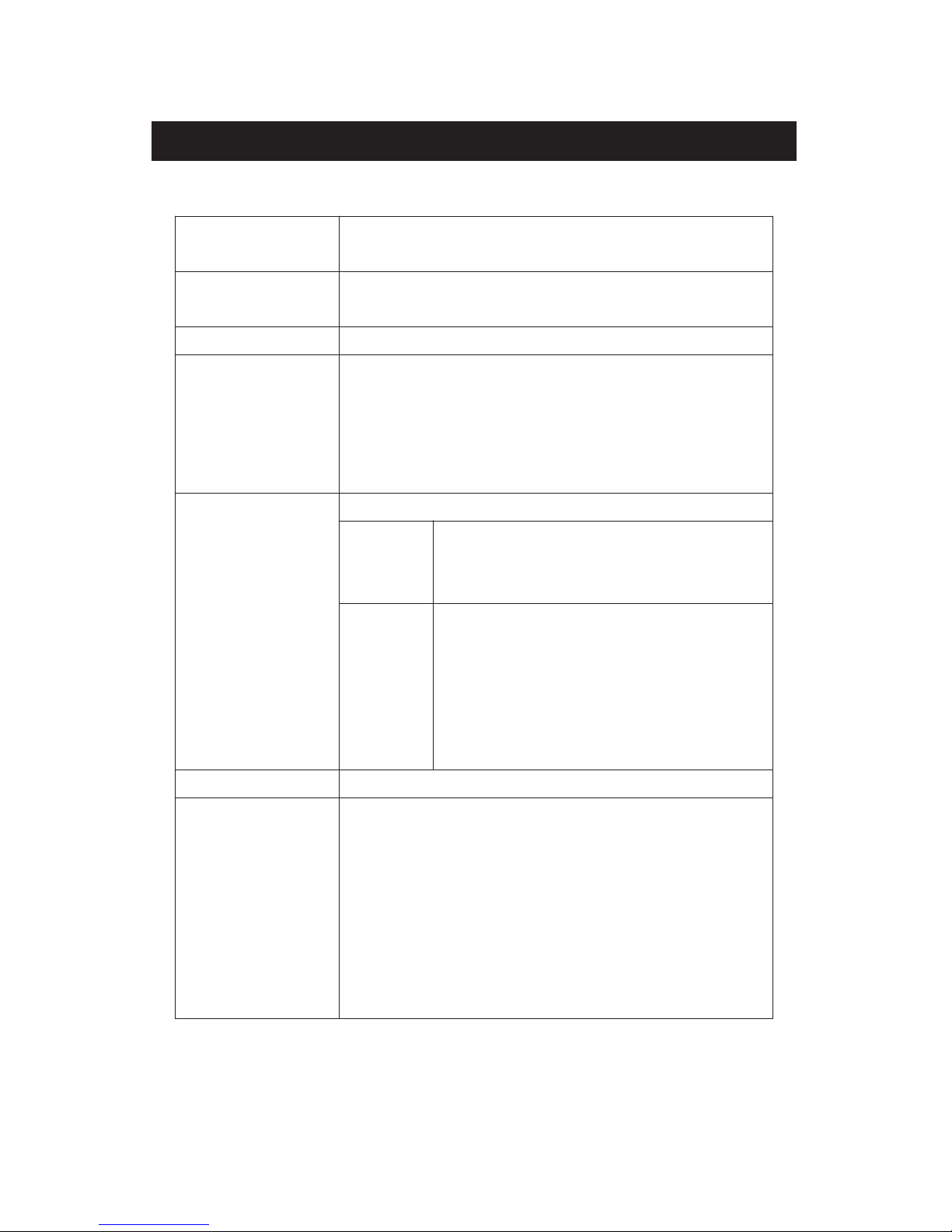
2-1 General Specifications
Circuit Custom one-chip of microprocessor LSI
circuit.
Display LCD size: 52 mm x 38 mm
LCD with green backlight ( ON/OFF ).
Channels T1, T2, T3, T4, T1-T2.
Sensor type Type K thermocouple probe.
Type J/T/E/R/S thermocouple probe.
PT 100 ohm probe
*
Cooperate with an 0.00385 alpha
coefficient, meet DIN IEC 751.
Resolution 0.1°C/1°C, 0.1°F/1°F.
Datalogger Auto 1 second to 3600 seconds
Sampling Time
@ Sampling time can set to 1 second,
Setting range
but memory data may loss.
Manual Push the data logger button
once will save data one time.
@ Set the sampling time to
0 second.
@ Manual mode, can also select the
1 to 99 position ( Location ) no.
Memory Card SD memory card. 1 GB to 16 GB.
Advanced * Set clock time ( Year/Month/Date,
setting Hour/Minute/ Second )
* Decimal point of SD card setting
* Auto power OFF management
* Set beep Sound ON/OFF
* Set temperature unit to °C or °F
* Set sampling time
* SD memory card Format
2
Page 6

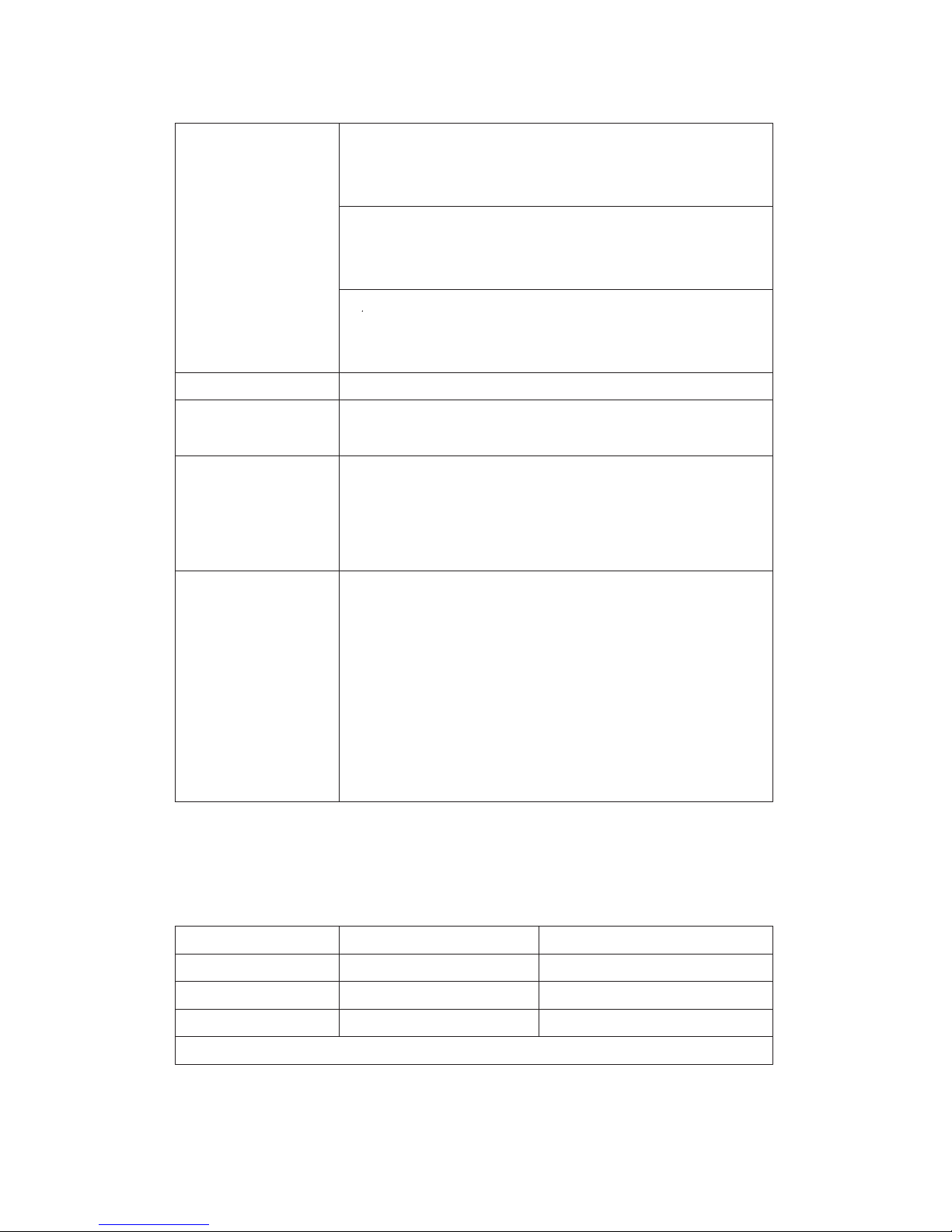
Temperature Automatic temp. compensation for the
Compensation type K/J/T/E/R/S thermometer.
Linear Linear Compensation for the full range.
Compensation
Offset Available for Type K/J/T/E/R/S and
Adjustment Pt 100 ohm.
Probe Input Type K/J/T/E/R/S
Socket 2 pin thermocouple socket.
Pt 100 ohm : Ear phone socket.
Over Indication Show " - - - - ".
Data Hold Freeze the display reading.
Memory Recall Maximum & Minimum value.
Sampling Time Approx. 1 second.
of Display
Data Output RS 232/USB PC computer interface.
* Connect the optional RS232 cable
UPCB-02 will get the RS232 plug.
* Connect the optional USB cable
USB-01 will get the USB plug.
Power off Auto shut off saves battery life or
manual off by push button.
Operating 0 to 50°C.
Temperature
Operating Less than 85% R.H.
Humidity
Power Supply
*
A
6-AA alkaline batteries
*
A
DC 9V adapter input. ( AC/DC power
adapter is optional ).
3
Page 7
Power Current Normal operation ( w/o SD card save
data and LCD Backlight is OFF) :
Approx. DC 8.5 mA.
When SD card save the data but and
LCD Backlight is OFF) :
Approx. DC 30 mA.
*AIf LCD backlight on, the power
consumption will increase approx.
14 mA.
Weight 489 g/1.08 LB.
Dimension 177 x 68 x 45 mm
(7.0 x 2.7x 1.9 inch)
Accessories *Instruction Manual
Included
Optional
Accessories
* USB cable, USB-01.
* RS232 cable, UPCB-02.
* Data Acquisition software,
SW-U801-WIN.
* AC to DC 9V adapter.
* Hard carrying case, CA-06.
* Soft carrying case, CA-05A.
2-2 Electrical Specifications (23± 5°C)
PT 100 ohm
Resolution Range Accuracy
0.1 -199.9 to 850.0°C ± ( 0.4 % + 1°C)
0.1 -327.0 to 999.9°F ± ( 0.4 % + 1.8°F)
1 1000 to 1562°F ± ( 0.4 % + 2°F)
*
Pt 100 ohm probe TP-101 is the optional accessory.
4
*4 Type K Thermocouples
*6-AA Alkaline Batteries
*2 GB-SD (2 GB SD Card)
Page 8

Type K/J/T/E/R/S
Sensor Resolution Range Accuracy
Type
T
ype K 0.1°C -50.1 to -100.0°C ± ( 0.4 % + 1°C )
-50.0 to 999.9°C ± ( 0.4 % + 0.5°C)
1°C 1000 to 1300°C ± ( 0.4 % + 1°C)
0.1°F -58.1 to -148.0°F ± ( 0.4 % + 1.8°F)
-58.0 to 999.9°F ± ( 0.4 % + 1°F)
1°F 1000 to 2372°F ± ( 0.4 % + 2°F)
T
ype J 0.1°C -50.1 to -100.0°C ± ( 0.4 % + 1°C)
-50.0 to 999.9°C ± ( 0.4 % + 0.5°C)
1°C 1000 to 1150°C ± ( 0.4 % + 1°C)
0.1°F -58.1 to -148.0°F ± ( 0.4 % + 1.8°F)
-58.0 to 999.9°F ± ( 0.4 % + 1°F)
1°F 1000 to 2102°F ± ( 0.4 % + 2°F)
T
ype T 0.1°C -50.1 to -100.0°C ± ( 0.4 % + 1°C)
-50.0 to 400.0°C ± ( 0.4 % + 0.5°C)
0.1°F -58.1 to -148.0°F ± ( 0.4 % + 1.8°F)
-58.0 to 752.0°F ± ( 0.4 % + 1°F)
T
ype E 0.1°C -50.1 to -100.0°C ± ( 0.4 % + 1°C)
-50.0 to 900.0°C ± ( 0.4 % + 0.5°C)
0.1°F -58.1 to -148.0°F ± ( 0.4 % + 1.8°F)
-58.0 to 999.9°F ± ( 0.4 % + 1°F)
1°F 1000 to 1652°F ± ( 0.4 % + 2°F)
T
ype R 1°C 0 to 600°C ± ( 0.5 % + 1°C)
601 to 1700°C ± ( 0.5 % + 1°C)
1°F 32 to 1112°F ± ( 0.5 % + 2°F)
1113 to 3092°F ± ( 0.5 % + 2°F)
T
ype S 1°C 0 to 600°C ± ( 0.5 % + 1°C)
601 to 1500°C ± ( 0.5 % + 1°C)
1°F 32 to 1112°F ± ( 0.5 % + 2°F)
1113 to 2732°F ± ( 0.5 % + 2°F)
Remark :
a. Accuracy value is specified for the meter only.
b. Accuracy is tested under the meter's environment temperature
within 23 ± 5°C.
c. Linearity Correction :
Memorize the thermocouple's curve into the intelligent CPU
circuit,
@ Above specification tests under the environment RF Field Strength
less than 3 V/M & frequency less than 30 MHz only.
5
Page 9
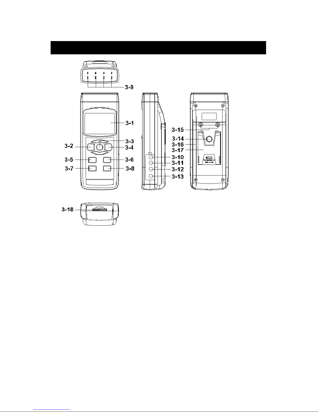
3. FRONT PANEL DESCRIPTION
Fig. 1
3-1 Display.
3-2 Power Button (ESC, Backlight Button)
3-3 Hold Button (Next Button)
3-4 REC Button (Enter Button)
3-5 Type Button (▲ Button, L Button)
3-6 T1-T2 Button (▼ Button, R Button)
3-7 SET Button (Time check Button)
3-8 Logger Button (OFFSET Button, Sampling time check Button)
3-9 T1,T2,T3,T4 input socket ( Type K, Type J )
3-10 PT1 input socket (Pt 100 ohm)
3-11 PT2 input socket (Pt 100 ohm)
3-12 RS-232 output terminal
3-13 DC 9V adapter socket
3-14 Tripod Fix Nut
3-15 Battery Cover Screws
3-16 Battery compartment/Cover
3-17 Stand
3-18 SD card socket
6
Page 10

4. MEASURING PROCEDURE
4-1 Type K measurement
1)Power on the meter by pressing the “Power button”
( 3-2, Fig. 1 ) once.
* After the meter is on, pressing the
“Power button” once ( > 2 sec ) will turn off
the meter.
2)Meter default Temp. sensor type is Type K, the display
will show “K” indicator.
The default temperature unit is °C (°F), the method
to change the Temp. unit from °C to °F or °F to °C,
please refer to Chapter 7-5, page 18.
3)Insert the Type K probes into the “T1, T2, T3, T4 input
socket” ( 3-9, Fig. 1).
The LCD will show the 4 channels ( T1, T2, T3, T4 )
temperature value at the same time.
* If the certain channels do not insert the temperature
probes, the relative channel display will show over
range " - - - - - ".
4-2 Type J/T/E/R/S measurement
All the measuring procedures are same as the Type K
(section 4-1 ) except to select the Temp. Sensor type to
“ Type J/K/T/E/R/S” by pressing the “Type Button” ( 3-5,
Fig. 1 ) once in sequence until the up LCD display shows the
“J/T/E/R/S” indicator.
7
Page 11

4-3 Pt 100 ohm measurement
1)All the measuring procedures are same as the Type K
(section 4-1 ) except to select the Temp. Sensor type to
“Pt” by pressing the “Type Button” (3-5, Fig. 1)
once in sequence
until the right down LCD display shows “Pt” text as :
Pt
2)Insert a Pt 100 ohm probe to
PT1 input socket (3-10, Fig. 1)
PT2 input socket (3-11, Fig. 1)
* The Pt 100 ohm measurement only allow
max. two channels ( two probes ) input.
4-4 T1-T2 measurement
When the meter has two installed probes :
Type K/J/T/E/R/S : T1, T2 input socket
Pt 100 ohm : PT1, PT2 input socket
Pressing the “T1-T2 button” ( 3-6, Fig. 1 ), display will
show the difference temperature value between T1, T2
( PT1, PT2 ) as :
T1 °C °C
T1 26.2 1-2
T2 °C °C
T2 26.6 -0.4 T1-T2 value
8
Page 12

4-5 Data Hold
During measurement mode, press the “Hold Button”
(3-3, Fig. 1) once will hold the measured value & the LCD
will display a “HOLD” symbol.
Pressing the “Hold Button” once again will release the data
hold function.
4-6 Data Record (Max., Min. reading)
1)The data record function records the maximum and
minimum readings. Press the “REC Button” ( 3-4, Fig.
1 ) once to start the Data Record function and there
will be a “REC” symbol on the display.
2)With the “REC” symbol on the display:
a) Press the “REC Button” ( 3-4, Fig. 1 ) once, the
“REC MAX” symbol along with the maximum value
will appear on the display.
If you wish to delete the maximum value, just press
the “Hold Button” (3-3, Fig. 1) once, the display
will show the “REC” symbol only & execute the
memory function continuously.
b)Press the “REC Button” (3-4, Fig. 1) again, the
“REC MIN” symbol along with the minimum value
will appear on the display.
If you wish to delete the minimum value, just press the
“Hold Button” (3-3, Fig. 1) once, the display will
show the “REC” symbol only & execute the
memory function continuously.
c) To exit the memory record function, just press the
“REC” button > 2 seconds. The display will revert to
the current reading.
9
Page 13

4-7 LCD Backlight ON/OFF
After power ON, the “LCD Backlight” will light
automatically. While in measurement mode, press the
“Backlight Button” (3-2, Fig.1) once will turn OFF the
“LCD Backlight”.
Press the “Backlight Button” once again will turn ON the
“LCD Backlight”.
5. DATALOGGER
5-1 Preparation before executing datalogger function
a. Insert the SD card
Prepare a " SD memory card " ( 1 GB to 16 GB, optional ),
insert the SD card into the " SD card socket " ( 3-18, Fig. 1).
The front panel of the SD card should face against the
down case.
b. SD card Format
If using the SD card for the first time, it is recommended
to make the “SD card Format” first. Please refer to
chapter 7-7 ( page 19 ).
c. Time setting
If using the meter for the first time, you should adjust the
clock time exactly, please refer chapter 7-1 ( page 16 ).
d. Decimal format setting
The numerical data structure of the SD card
is defaulted “ . ” as the decimal. For
example “20.6” “1000.53”. In certain
countries (Europe) the default is “ , ” as the
decimal point. For example “20, 6”
“1000,53”. Under such situation, you should
change the Decimal character at first, details
of setting the Decimal point, refer to Chapter
7-2, page 17.
10
Page 14

5-2 Auto Datalogger (Set sampling time ≥ 1 second )
a. Start the datalogger
Press the “REC Button (3-4, Fig. 1) once , the LCD will
show the text “REC”, then press the “Logger Button”
(3-8, Fig. 1), the “REC” will flash and the beeper will
sound at the same time the measuring data along with
the time information will be saved into the memory circuit.
Remark :
*
How to set the sampling time, refer to Chapter 7-6,
page 19.
*
How to enable the beeper sound, refer to
Chapter 7-4, page 18.
b. Pause the datalogger
During execute the Datalogger function, press the
“Logger Button” (3-8, Fig. 1) once will pause the
Datalogger function (stop to save the measuring data
into the memory circuit temporally). At the same time
the text of " REC " will stop flashing.
Remark :
If you press the “Logger Button” ( 3-8, Fig. 1 ) once again,
it will execute the Datalogger again, the text of “REC” will
be flashing .
c.. Finish the Datalogger
To pause the Datalogger, press the “REC Button”
( 3-4, Fig. 1) continuously for at least two seconds, the “REC”
indicator will disappear and stop the Datalogger.
11
Page 15

5-3 Manual Datalogger (Set sampling time = 0
second)
a. Set sampling time is to 0 second
Press the “REC Button” (3-4, Fig. 1) once , the LCD will
show the text “REC”, then press the “Logger Button”
( 3-8, Fig. 1 ) once, the “REC” will flash once and the
Beeper will sound once, at the same time the measuring
data along the time information and the Position no. will
be saved into the memory circuit.
Remark :
* For the 4 channels measurement, the right lower
Display will show the Position/Location no. (P1, P2...
P99) and the T4 measurement value alternately.
* During execute the Manual Datalogger, use
the “▲” Button (3-5, Fig. 1) or “▼” Button (3-6,
Fig.1) to set the measuring position (1 to 99, for
example room 1 to room 99) to identify the
measurement location.
b. Finish the Datalogger
Press the “REC Button” (3-4, Fig. 1) continuously at
least two seconds, the “REC” indication will be
disappear and stop the Datalogger.
5-4 Check time information
During the normal measurement (not execute the
Datalogger). If you press “Time check Button” (3-7, Fig. 1)
once, the lower LCD display will present the time
information of Year/Month, Date/Hour, Minute/Second.
12
Page 16

5-5 Check sampling time information
During the normal measurement mode (not execute the
Datalogger), If you press “Sampling Button” (3-8, Fig. 1)
once, the lower LCD display will present the Sampling
time information in seconds.
5-6 SD Card Data structure
1)When using for the first time, the SD card
will generate a folder:
TMA01
2)When using for the first time, to execute the Datalogger,
under the route TMA01\, will generate a new
file name TMA01001.XLS.
After this the Datalogger will save the data
to the file TMA01001.XLS until the data column
reaches 30,000 columns, then it will generate
a new file. For example TMA01002.XLS
3)Under the folder TMA01\, if the total files are greater
than 99 files, it will generate a new route, such as
TMA02\ ........
4)The file's route structure :
TMA01\
TMA01001.XLS
TMA01002.XLS
.....................
TMA01099.XLS
TMA02\
TMA02001.XLS
TMA02002.XLS
.....................
TMA02099.XLS
TMAXX\
.....................
.....................
Remark : XX : Max. value is 10.
13
Page 17

6. Saving data from the SD card
to the computer (EXCEL software)
1)After executing the Data Logger function, remove the
SD card from the “SD card socket” (3-18, Fig. 1).
2)Plug in the SD card into the Computer's SD card slot
or insert the SD card into the “SD card adapter”, then
connect the “SD card adapter” into the computer.
3)Power ON the computer and run the " EXCEL software ".
Down load the saving data file ( for example the file
name : TMA01001.XLS, TMA01002.XLS ) from the SD
card to the computer. The saved data will be displayed onto
the EXCEL software screen (for example as the below
EXCEL data screen). The user can use EXCEL
data to make further Data or Graphic analysis.
EXCEL data screen ( for example )
14
Page 18

EXCEL graphic screen (for example)
7. ADVANCED SETTING
Under do not execute the Datalogger function,
press the “SET Button” (3-7, Fig. 1) for at least two
seconds will enter the “Advanced Setting” mode.
Pressing the “Next” Button (3-3, Fig. 1) will in
sequence select the seven main functions, the lower
display will show:
dAtE.....
.
Set clock time ( Year/Month/Date, Hour/Minute/
Second )
dEC......
.
Set SD card Decimal character
PoFF..... Auto power OFF management
bEEP.....Set beeper sound ON/OFF
t-CF...... Select the Temp. unit to or ℃ ℉
SP-t...... Set sampling time ( Hour/Minute/Second )
Sd F..... SD memory card Format
15
Page 19

Remark :
While executing the "Advanced Setting" function,
if you press the “ESC” Button (3-2, Fig. 1) once,
you will exit the “Advanced Setting” function,
the LCD will return to the normal screen.
7-1 Set clock time (Year/Month/Date,
Hour/Minute/Second)
When the lower display show " dAtE "
1)Press the “Enter” Button (3-4, Fig. 1) once,
Use the “▲” Button (3-5, Fig. 1) or “▼” Button
(3-6, Fig. 1) to adjust the value (Setting start from
Year value). After the desired value is set, press the
“Enter” Button (3-4, Fig. 1) once will go to the
next value adjustment ( for example, first setting
value is Year then next to adjust Month, Date, Hour,
Minute, Second value ).
2)After setting all the time value (Year, Month, Date, Hour,
Minute, Second),
the screen will jump to " SD card Decimal character "
setting screen (Chapter 7-2).
Remark :
After the time value is setting, the internal clock will
run even when the Power is off.
16
Page 20

7-2 Decimal point of SD card setting
The numerical data structure default is “ . ”
as the decimal. For example “20.6” “1000.53”.
In certain countries (Europe) the “ , ” is used as
the decimal point. For example “20,6” “1000,53”.
When the lower display shows “dEC”
1)Use the “▲” Button ( 3-5, Fig. 1 ) or “▲” Button
( 3-6, Fig. 1 ) to select the upper value to " bASI " or
" Euro ".
bASI - Use “ . ” as the Decimal point with default.
Euro - Use “ , ” as the Decimal point with default.
2)After selecting the upper text to “bASI” or “Euro”,
pressing the “Enter” Button (3-4, Fig. 1) will save the
setting function with default.
7-3 Auto power OFF management
When the lower display shows “PoFF”
1)Use the “▲” Button ( 3-5, Fig. 1 ) or “▲” Button
(3-6, Fig. 1) to select the upper value to “yES” or “no”.
yES - Auto Power Off management will enable.
no - Auto Power Off management will disable.
2)After selecting the upper text to “yES” or “no”, pressing
the “Enter” Button ( 3-4, Fig. 1 ) will save the setting
function with default.
17
Page 21

7-4 Set beeper sound ON/OFF
When the lower display shows “bEEP”
1)Use the “▲” Button " ( 3-5, Fig. 1 ) or “▼” Button "
( 3-6, Fig. 1 ) to select the upper value to " yES " or
" no ".
yES - Meter's beep sound will be ON with default.
no - Meter's beep sound will be OFF with default.
2)After selecting the upper text to “yES” or “no”, press the
“Enter Button” (3-4, Fig. 1) will save the setting
function with default.
7-5 Select the Temp. unit to °C or °F
When the lower display shows “t-CF”
1)Use the “▲” Button " ( 3-5, Fig. 1 ) or “▼” Button
(3-6, Fig. 1) to select the upper Display text to “C” or
“F”.
C - Temperature unit is °C
F - Temperature unit is °F
2)After Display unit is selected to “C” or “F”, press the
“Enter” Button (3-4, Fig. 1) will save the setting
function with default.
18
Page 22

7-6 Set sampling time ( SecondS )
When the lower display shows “SP-t”
1)Use the “▲” Button (3-5, Fig. 1) or “▼” Button
(3-6, Fig. 1) to adjust the value (0, 1, 2, 5, 10, 30,60,
120, 300, 600, 1800,3600 seconds ).
Remark :
If selecting the sampling time to “0 second”, the
RDXL4SD will be ready for manual Datalogging.
2)After the Sampling value is selected, press the
“Enter” Button (3-4, Fig. 1) will save the setting
function with default.
7-7 SD memory card Format
When the lower display shows “Sd F”
1)Use the “▲” Button " (3-5, Fig. 1) or “▼” Button
(3-6, Fig. 1) to select the upper value to “yES” or
“no”.
yES - Intend to format the SD memory card
no - Not execute the SD memory card format
2)If selecting the upper to “yES”, press the “Enter” Button
(3-4, Fig. 1), the display will show text “yES Ent”.
To confirm again, pressing the “Enter” button once
will format the SD memory, clearing all existing
data that was already saved on the SD card.
19
Page 23

8. POWER SUPPLY from DC
ADAPTER
The meter can be powered by the DC 9V Power Adapter
(optional). Insert the plug of Power Adapter into
“DC 9V Power Adapter Input Socket” (3-13, Fig. 1).
The meter will power ON (The power Button
function is disabled).
9. BATTERY REPLACEMENT
1)When the left corner of LCD display shows “ ”, it
is necessary to replace the batteries. However, in-spec.
measurement may still be made for several hours after
the low battery indicator appears before the instrument
becomes inaccurate.
2)Remove the battery cover screws (3-15, Fig. 1)
and remove the battery cover (3-16, Fig. 1)
from the instrument and remove the battery.
3)Replace with DC 1.5 V battery (6-AA, Alkaline/heavy duty)
and replace the cover.
4)Make sure the battery cover is secured after changing
the batteries.
10. RS232 PC SERIAL INTERFACE
The instrument has RS232 PC serial interface via a 3.5
mm terminal ( 3-12, Fig. 1 ).
The data output is a 16 digit stream which can be
utilized for user's specific application.
A RS232 lead with the following connection will be
required to link the instrument with the PC serial port.
20
Page 24

CPreteM
(9W 'D" Connector)
Center Pin........................Pin 4
(3.5 mm jack plug)
Ground/shield.....................Pin 2
2.2 K
resistor
Pin 5
The 16 digits data stream will be displayed in the
following format :
D15 D14 D13 D12 D11 D10 D9 D8 D7 D6 D5 D4 D3 D2 D1 D0
Each digit indicates the following status :
D15 Start Word
D14 4
D13 When send the upper display data = 1
When send the lower display data = 2
D12, D11 Annunciator for Display
= 01 ℃ = 02℉
D10 Polarity
0 = Positive 1 = Negative
D9 Decimal Point(DP), position from right to the
left
0 = No DP, 1= 1 DP, 2 = 2 DP, 3 = 3 DP
D8 to D1 Display reading, D1 = LSD, D8 = MSD
For example :
If the display reading is 1234, then D8 to
D1 is : 00001234
D0 End Word
21
Page 25

RS232 FORMAT : 9600, N, 8, 1
Baud rate 9600
Parity No parity
Data bit no. 8 Data bits
Stop bit 1 Stop bit
11. OFFSET ADJUSTMENT
11-1 Type K/J/T/E/R/S offset adjustment
1)Set the function to Type K (or other type J/E/R/T/S).
2)Insert the probe to the T1 input socket (3-9, Fig. 1)
3)Pressing “Offset button” (3-8, Fig. 1) for at least
two seconds then release, the display will show:
SEt oFS
23.7 23.7
* If no probe is inserted
into T1, the meter will
measuring adjust
display “Err”
value value
* Use the " button "( 3-5, Fig. 1 ) " button " ( 3-6
Fig. 1 ) to adjust the desired value on right bottom
display.
* Pressing " Enter button " ( 3-4, Fig. 1 ) once, the
adjustment value will be saved into memory, then return
to normal measuring screen to finish the offset
adjustment procedures.
* The above offset adjustment for Type K/J/T/E/R/S is
valid for T1, T2, T3, T4 at the same time.
7-2 Pt 100 ohm offset adjustment
1)Set the function to Pt 100 ohm.
2)Insert a Pt 100 ohm probe to the PT1 ( PT2 ) input socket.
22
Page 26

3)Pressing “Offset” button (3-8, Fig. 1)
for at least two seconds then release, the
display will show :
SEt oFS
Pt 1 Pt 2
4)If you wish to make the offset adjustment for Pt 1, please
insert the probe to PT1 input socket. Press the “L” button
(3-5, Fig. 1) once, the display will show example as following.
If you wish to make the offset adjustment for Pt 2, please
insert the probe to PT2 input socket. Press the “R” button
( 3-6, Fig. 1 ) once, the display will show example as
following.
SEt oFS
23.7 23.7
* If no probe is inserted
into PT1, PT2 input
measuring adjust
socket, the meter
value value
will show “Err”
* Use the “▲” button (3-5, Fig. 1) “▼” button (3-6,
Fig. 1) to adjust the desired value on right bottom
display.
* Pressing “Enter” button (3-4, Fig. 1) once, the
adjustment value will be saved into the memory
then return to normal measuring screen to finish
the offset adjustment procedures.
* The above offset adjustment for Pt 100 ohm is
valid for PT1, PT2 individually.
23
Page 27

WARRANTY/DISCLAIMER
OMEGA ENGINEERING, INC. warrants this unit to be free of defects in materials and
workmanship for a period of 13 months from date of purchase. OMEGA’s Warranty adds an
additional one (1) month grace period to the normal one (1) year product warranty to cover
handling and shipping time. This ensures that OMEGA’s customers receive maximum
coverage on each product.
If the unit malfunctions, it must be returned to the factory for evaluation. OMEGA’s Customer
Service Department will issue an Authorized Return (AR) number immediately upon phone or
written request. Upon examination by OMEGA, if the unit is found to be defective, it will be
repaired or replaced at no charge. OMEGA’s WARRANTY does not apply to defects resulting
from any action of the purchaser, including but not limited to mishandling, improper interfacing,
operation outside of design limits, improper repair, or unauthorized modification. This
WARRANTY is VOID if the unit shows evidence of having been tampered with or shows evidence
of having been damaged as a result of excessive corrosion; or current, heat, moisture or vibration; improper specification; misapplication; misuse or other operating conditions outside of
OMEGA’s control. Components which wear are not warranted, including but not limited to
contact points, fuses, and triacs.
OMEGA is pleased to offer suggestions on the use of its various products. However,
OMEGA neither assumes responsibility for any omissions or errors nor assumes liability
for any damages that result from the use of its products in accordance with information
provided by OMEGA, either verbal or written. OMEGA warrants only that the parts
manufactured by it will be as specified and free of defects. OMEGA MAKES NO OTHER
WARRANTIES OR REPRESENTATIONS OF ANY KIND WHATSOEVER, EXPRESS OR
IMPLIED, EXCEPT THAT OF TITLE, AND ALL IMPLIED WARRANTIES INCLUDING ANY
WARRANTY OF MERCHANTABILITY AND FITNESS FOR A PARTICULAR PURPOSE ARE
HEREBY DISCLAIMED. LIMITATION OF LIABILITY: The remedies of purchaser set forth
herein are exclusive, and the total liability of OMEGA with respect to this order, whether
based on contract, warranty, negligence, indemnification, strict liability or otherwise, shall
not exceed the purchase price of the component upon which liability is based. In no event
shall OMEGA be liable for consequential, incidental or special damages.
CONDITIONS: Equipment sold by OMEGA is not intended to be used, nor shall it be used: (1) as
a “Basic Component” under 10 CFR 21 (NRC), used in or with any nuclear installation or activity;
or (2) in medical applications or used on humans. Should any Product(s) be used in or with any
nuclear installation or activity, medical application, used on humans, or misused in any way,
OMEGA assumes no responsibility as set forth in our basic WARRANTY/ DISCLAIMER language,
and, additionally, purchaser will indemnify OMEGA and hold OMEGA harmless from any liability
or damage whatsoever arising out of the use of the Product(s) in such a manner.
RETURN REQUESTS/INQUIRIES
Direct all warranty and repair requests/inquiries to the OMEGA Customer Service Department.
BEFORE RETURNING ANY PRODUCT(S) TO OMEGA, PURCHASER MUST OBTAIN AN
AUTHORIZED RETURN (AR) NUMBER FROM OMEGA’S CUSTOMER SERVICE DEPARTMENT
(IN ORDER TO AVOID PROCESSING DELAYS). The assigned AR number should then be
marked on the outside of the return package and on any correspondence.
The purchaser is responsible for shipping charges, freight, insurance and proper packaging to
prevent breakage in transit.
FOR WARRANTY
RETURNS, please have
the following information available BEFORE
contacting OMEGA:
1. Purchase Order number under which
the product was PURCHASED,
2. Model and serial number of the product
under warranty, and
3. Repair instructions and/or specific
problems relative to the product.
FOR NON-WARRANTY REPAIRS,
consult
OMEGA for current repair charges. Have the
following information available BEFORE
contacting OMEGA:
1. Purchase Order number to cover the COST
of the repair,
2. Model and serial number of the product, and
3. Repair instructions and/or specific problems
relative to the product.
OMEGA’s p olicy is to make running changes, no t model changes, wh enever an improveme nt is possible.
This affords our customers the latest in technology and engineering.
OMEGA is a registered trademark of OMEGA ENGINEERING, INC.
© Copyright 2010 OMEGA ENGINEERING, INC. All rights reserved. This document may not be copied, photocopied,
reproduced, translated, or reduced to any electronic medium or machine-readable form, in whole or in part, without
the prior written consent of OMEGA ENGINEERING, INC.
Page 28

Where Do I Find Everything I Need for
Process Measurement and Control?
OMEGA…Of Course!
Shop online at omega.com
sm
TEMPERATURE
䡺⻬
Thermocouple, RTD & Thermistor Probes, Connectors, Panels & Assemblies
䡺⻬
Wire: Thermocouple, RTD & Thermistor
䡺⻬
Calibrators & Ice Point References
䡺⻬
Recorders, Controllers & Process Monitors
䡺⻬
Infrared Pyrometers
PRESSURE, STRAIN AND FORCE
䡺⻬
Transducers & Strain Gages
䡺⻬
Load Cells & Pressure Gages
䡺⻬
Displacement Transducers
䡺⻬
Instrumentation & Accessories
FLOW/LEVEL
䡺⻬
Rotameters, Gas Mass Flowmeters & Flow Computers
䡺⻬
Air Velocity Indicators
䡺⻬
Turbine/Paddlewheel Systems
䡺⻬
Totalizers & Batch Controllers
pH/CONDUCTIVITY
䡺⻬
pH Electrodes, Testers & Accessories
䡺⻬
Benchtop/Laboratory Meters
䡺⻬
Controllers, Calibrators, Simulators & Pumps
䡺⻬
Industrial pH & Conductivity Equipment
DATA ACQUISITION
䡺⻬
Data Acquisition & Engineering Software
䡺⻬
Communications-Based Acquisition Systems
䡺⻬
Plug-in Cards for Apple, IBM & Compatibles
䡺⻬
Data Logging Systems
䡺⻬
Recorders, Printers & Plotters
HEATERS
䡺⻬
Heating Cable
䡺⻬
Cartridge & Strip Heaters
䡺⻬
Immersion & Band Heaters
䡺⻬
Flexible Heaters
䡺⻬
Laboratory Heaters
ENVIRONMENTAL
MONITORING AND CONTROL
䡺⻬
Metering & Control Instrumentation
䡺⻬
Refractometers
䡺⻬
Pumps & Tubing
䡺⻬
Air, Soil & Water Monitors
䡺⻬
Industrial Water & Wastewater Treatment
䡺⻬
pH, Conductivity & Dissolved Oxygen Instruments
M4963/1010
 Loading...