

Page 1

User’s Guide
Shop online at
omega.com
e-mail: info@omega.com
For latest product manuals:
omegamanual.info
RD100B
Programmable Recorder
Page 2

OMEGAnet®Online Service Internet e-mail
omega.com info@omega.com
Servicing North America:
U.S.A.: One Omega Drive, P.O. Box 4047
ISO 9001 Cer
tified
Stamford, CT 06907-0047
TEL: (203) 359-1660 FAX: (203) 359-7700
e-mail: info@omega.com
Canada: 976 Bergar
Laval (Quebec) H7L 5A1, Canada
TEL: (514) 856-6928 FAX: (514) 856-6886
e-mail: info@omega.ca
For immediate technical or application assistance:
U.S.A. and Canada: Sales Service: 1-800-826-6342 / 1-800-TC-OMEGA
Customer Service: 1-800-622-2378 / 1-800-622-BEST
Engineering Service: 1-800-872-9436 / 1-800-USA-WHEN
®
®
®
Mexico: En Espan˜ ol: (001) 203-359-7803 e-mail: espanol@omega.com
FAX: (001) 203-359-7807 info@omega.com.mx
Servicing Europe:
Benelux: Postbus 8034, 1180 LAAmstelveen, The Netherlands
TEL: +31 (0)20 3472121 FAX: +31 (0)20 6434643
Toll Free in Benelux: 0800 0993344
e-mail: sales@omegaeng.nl
Czech Republic: Frystatska 184, 733 01 Karviná, Czech Republic
TEL: +420 (0)59 6311899 FAX: +420 (0)59 6311114
Toll Free: 0800-1-66342 e-mail: info@omegashop.cz
France: 11, rue Jacques Cartier, 78280 Guyancourt, France
TEL: +33 (0)1 61 37 2900 FAX: +33 (0)1 30 57 5427
Toll Free in France: 0800 466 342
e-mail: sales@omega.fr
Germany/Austria: Daimlerstrasse 26, D-75392 Deckenpfr
TEL: +49 (0)7056 9398-0
Toll Free in Germany: 0800 639 7678
e-mail: info@omega.de
United Kingdom: One Omega Drive, River Bend Technology Centre
ISO 9002 Certified Northbank, Irlam, Manchester
M44 5BD United Kingdom
TEL: +44 (0)161 777 6611 FAX: +44 (0)161 777 6622
Toll Free in United Kingdom: 0800-488-488
e-mail: sales@omega.co.uk
onn, Germany
AX: +49 (0)7056 9398-29
F
It is the policy of OMEGA Engineering, Inc. to comply with all worldwide safety and EMC/EMI
regulations that apply. OMEGA is constantly pursuing certification of its products to the European New
Approach Directives. OMEGA will add the CE mark to every appropriate device upon certification.
The information contained in this document is believed to be correct, but OMEGA accepts no liability for any
errors it contains, and reserves the right to alter specifications without notice.
WARNING: These products are not designed for use in, and should not be used for, human applications.
Page 3

Foreword
Notes
Thank you for purchasing the OMEGA RD100B Recorder.
This manual describes the functions (excluding the communication functions), installation
and wiring procedures, operating procedures, and lists the handling precautions of the
RD100B Recorder. To ensure correct use, please read this manual thoroughly before
beginning operation.
The following three manuals including this manual are available for the RD100B
Recorder.
• Electronic Manuals Provided on the Accompanying CD-ROM
Manual Title Manual No. Description
RD100B Recorder M-4231 This manual.
User’s Guide
RD100B/RD1800B M-4233 Explains the communication functions of the
Communication Interface RD100B Recorder using Ethernet interface and
User’s Manual the RS-422A/485 communication interface.
• Paper Manual
Manual Title Manual No. Description
RD100B Recorder M-4232 Explains concisely the operations of the
Operation Guide RD100B Recorder.
• The contents of this manual are subject to change without prior notice as a result of
continuing improvements to the instrument’s performance and functions.
• Every effort has been made in the preparation of this manual to ensure the accuracy
of its contents. However, should you have any questions or find any errors, please
contact OMEGA.
• Copying or reproducing all or any part of the contents of this manual without
permission is strictly prohibited.
• The TCP/IP software of this product and the document concerning the TCP/IP
software have been developed/created based on the BSD Networking Software,
Release 1 that has been licensed from the University of California.
Trademarks
Revisions
• Microsoft, MS-DOS, Windows, Windows NT, and Windows XP are either registered
trademarks or trademarks of Microsoft Corporation in the United States and/or other
countries.
• Adobe, Acrobat, and PostScript are trademarks of Adobe Systems incorporated.
• For purposes of this manual, the TM and ® symbols do not accompany their
respective trademark names or registered trademark names.
• Company and product names that appear in this manual are trademarks or registered
trademarks of their respective holders.
1st Edition December 2004
2nd Edition March 2005
3rd Edition August 2005
i
Page 4
Recorder’s Version and Functions Described in This
Manual
The contents of this manual corresponds to the recorder with version 1.11.
RD100B Versions and Functions
Version
1.02 or earlier
1.11
Suffix Code
–
–
–
–
–
/C3
/C7
Added or Modified Functions
–
(Added) The printout/display format of the date can be changed.
(Added) Key operation to move the printer carriage near the center
position so that the ribbon cassette can be replaced with
the power turned ON (dot model)
(Changed) Selectable range of alarm values during linear scaling
(including 1-5V and SQRT) is –5% to 105% of the scale
span.
(Changed) Specify the date/time for switching DST and standard time
by the month, the nth day of the week of that month, and
time.
(Added) Modbus slave protocol
Two-wire system
(Changed) Users with the same user name cannot be registered.
Reference
–
Section 7.19
Section 3.4
Section 5.2
Sections 5.5
and 6.13
Communication
manual
Communication
manual
• Checking the Version Number
You can check the version number on the System display.
The System display cannot be shown at the factory default condition.
First, register the System display to the display screen.
• Procedure of registering the System display to the display screen: See section 8.2.
• Procedure of displaying the System display: The screen switches each time the
key repeatedly until System display is shown. The displayed contents on the System display switches every 3
seconds. Check the number shown by the “Version:” item.
key is pressed. Press the
DISP
Software (Sold Separately)
The RD100B Configuration Software cannot set the new functions (indicated above) available on RD100B
version 1.11. The new functions are planned to be supported on the configuration software to be released after
November 2005.
DISP
ii
Page 5

Safety Precautions
The general safety precautions described here must be observed during all phases of operation.
Safety Standards and EMC Standards
This recorder conforms to IEC safety class I (provided with terminal for protective grounding), Installation Category
II, Measurement Category II (CAT II), and EN61326-1 (EMC standard), class A (use in a commercial, industrial, or
business environment). This recorder is designed for indoor use.
About This Manual
• This manual should be read by the end user.
• Read this manual thoroughly and have a clear understanding of the product before operation.
• This manual explains the functions of the product. OMEGA does not guarantee that the product will suit a
particular purpose of the user.
• Under absolutely no circumstances may the contents of this manual be transcribed or copied, in part or in
whole, without permission.
• The contents of this manual are subject to change without prior notice.
• Every effort has been made in the preparation of this manual to ensure the accuracy of its contents. However,
should you have any questions or find any errors or omissions, please contact OMEGA.
Precautions Related to the Protection, Safety, and Alteration of the Product
• The following safety symbols are used on the product and in this manual.
“Handle with care.” To avoid injury and damage to the instrument, the operator must refer to the
explanation in the manual.
Protective ground terminal
AC
“High temperature.” To avoid injury caused by hot surface, do not touch locations where this
symbol appears.
• For the protection and safe use of the product and the system controlled by it, be sure to follow the instructions
and precautions on safety that are stated in this manual whenever you handle the product. Take special note
that if you handle the product in a manner that violate these instructions, the protection functionality of the
product may be damaged or impaired. In such cases, OMEGA does not guarantee the quality, performance,
function, and safety of the product.
• When installing protection and/or safety circuits such as lightning protection devices and equipment for the
product and control system or designing or installing separate protection and/or safety circuits for fool-proof
design and fail-safe design of the processes and lines that use the product and the control system, the user
should implement these using additional devices and equipment.
• If you are replacing parts or consumable items of the product, make sure to use parts specified by OMEGA.
• This product is not designed or manufactured to be used in critical applications that directly affect or threaten
human lives. Such applications include nuclear power equipment, devices using radioactivity, railway facilities,
aviation equipment, air navigation facilities, aviation facilities, and medical equipment. If so used, it is the user’s
responsibility to include in the system additional equipment and devices that ensure personnel safety.
• Do not modify this product.
iii
Page 6

Safety Precautions
• Power Supply
Ensure that the source voltage matches the voltage of the power supply before turning ON the power.
• Protective Grounding
Make sure to connect the protective grounding to prevent electric shock before turning ON the power.
• Necessity of Protective Grounding
Never cut off the internal or external protective earth wire or disconnect the wiring of the protective earth
terminal. Doing so invalidates the protective functions of the instrument and poses a potential shock
hazard.
• Defect of Protective Grounding
Do not operate the instrument if the protective earth or fuse might be defective. Make sure to check
them before operation.
• Do Not Operate in an Explosive Atmosphere
Do not operate the instrument in the presence of flammable liquids or vapors. Operation in such
environments constitutes a safety hazard.
• Do Not Remove Covers
The cover should be removed by OMEGA’s qualified personnel only. Opening the cover is dangerous,
because some areas inside the instrument have high voltages.
• External Connection
Connect the protective grounding before connecting to the item under measurement or to an external
control unit.
• Damage to the Protective Structure
Operating the recorder in a manner not described in this manual may damage its protective structure.
WARNING
Exemption from Responsibility
• OMEGA makes no warranties regarding the product except those stated in the WARRANTY that is provided
separately.
• OMEGA assumes no liability to any party for any loss or damage, direct or indirect, caused by the user or any
unpredictable defect of the product.
Handling Precautions of the Software
• OMEGA makes no warranties regarding the software accompanying this product except those stated in the
WARRANTY that is provided separately.
• Use the software on a single PC.
• You must purchase another copy of the software, if you are to use the software on another PC.
• Copying the software for any purposes other than backup is strictly prohibited.
• Please store the original media containing the software in a safe place.
• Reverse engineering, such as decompiling of the software, is strictly prohibited.
• No portion of the software supplied by OMEGA may be transferred, exchanged, sublet, or leased for use by any
third party without prior permission by OMEGA.
iv
Page 7
Checking the Contents of the Package
Unpack the box and check the contents before operating the recorder. If some of the
contents are not correct or missing or if there is physical damage, contact the dealer
from which you purchased them.
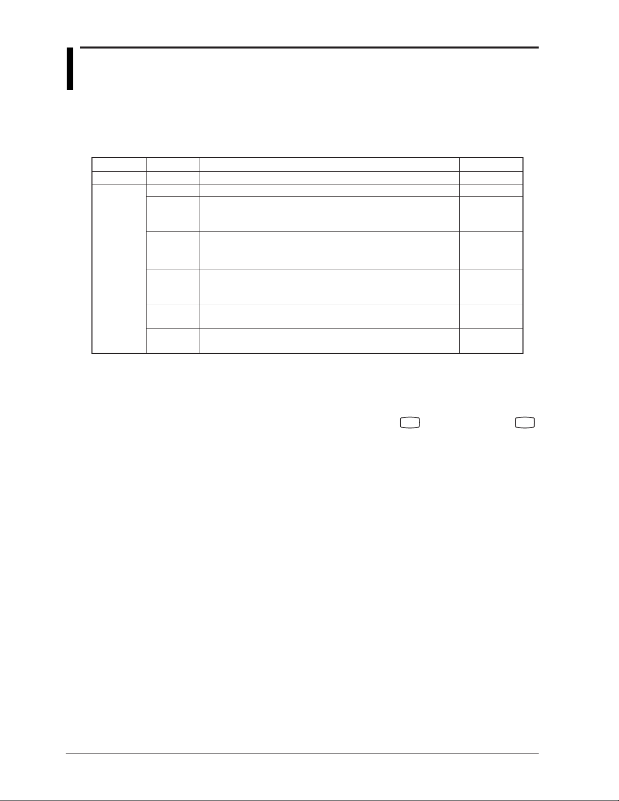
Checking the Model
A name plate is affixed to the recorder. Check that the model name and suffix code
given on the name plate on the rear panel match those on your order.
RD100B RECORDER
MODEL
R
SUFFIX
C
US
LR99988
SUPPLY
FREQUENCY
NO.
N200
OMEGA
STYLE
Made in China
MODEL and SUFFIX Code
Model
RD101B
RD102B
RD103B
RD104B
RD106B
1 /A1, /A2, and /A3 cannot be specified simultaneously.
2 /A3 and /F1 cannot be specified simultaneously.
3 /C3 and /C7 cannot be specified simultaneously.
4 /H2 and /N2 cannot be specified simultaneously.
5 Valid only on the model 436106.
6 14 types of input including Pt50 RTD, PR40-20, and Platinel TC
Suffix Code
-1
-2
Optional Code
Description
RD100B 1 pen recorder
RD100B 2 pen recorder
RD100B 3 pen recorder
RD100B 4 pen recorder
RD100B 6 dot recorder
Japanese
English & deg F / DST
/A1 Alarm output relay 2 points
/A2 Alarm output relay 4 points
/A3 Alarm output relay 6 points
/C3 RS-422A/485 interface
/C7 Ethernet (10BASE-T) interface
/F1 Fail/Chart end detection and output
/H2 Clamped input terminal
/H3 Non-glare door glass
/M1 Mathematical function
/N1 Cu10, Cu25 RTD input
/N2 3 legs isolated RTD
/N3 Expansion inputs
/R1 Remote control 5 points
1
1
1, 2
3
3
2
4
4, 5
6
v
Page 8
Checking the Contents of the Package
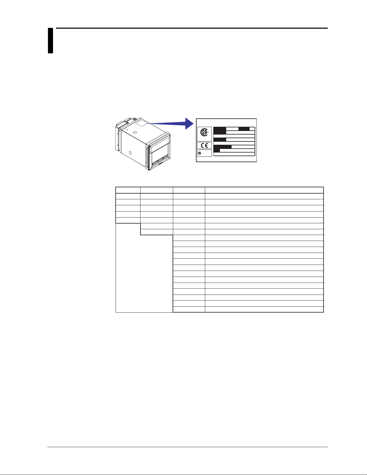
Standard Accessories
The standard accessories below are supplied with the recorder. Check that all contents
are present and undamaged.
Z-fold chart
paper
Manuals for the RD100B/RD1800B
Z-fold chart paper 1 1 1 1 1
Ribbon cassette
Disposable felt pen
Plotter pen
Mounting bracket
Manuals for the RD100B/RD1800B (CD-ROM)
RD100B Recorder Operation Guide
M-4232
Ribbon
cassette
(CD-ROM)
Item 1-Pen 2-Pen 3-Pen 4-Pen Dot Printing
Optional Accessories (Sold Separately)
The optional accessories below are available for purchase separately. If you make an
order, make sure that all contents are present and undamaged.
For information about ordering accessories, contact the dealer from which you
purchased the recorder.
Disposable
felt pen
RD100B Recorder Operation Guide
Red
Green
Blue
Violet
Purple
Plotter pen Mounting bracket
M-4232
---- 1
1111 -
-111 -
--11 -
---1 1111 2222 2
1111 1
1111 1
Software (Sold Separately)
vi
Item
Z-fold chart paper
Ribbon cassette
Red
Disposable felt pen
Plotter pen
Mounting bracket
Shunt resistor
for the screw terminal (standard)
Shunt resistor
for the clamped input terminal (/H2)
Green
Blue
Violet
Purple
Item
RD100B Configuration software
* The new functions of the RD100B version 1.11 are planned to be supported on the
configuration software to be released after November 2005.
Model
(Part Number
RD100-ZFP-10 1
RD100-RC
RD100A-01
RD100A-02
RD100A-03
RD100A-04
RD100A-11
B9900BX
415920
415921
415922
438920
438921
438922
Model
1
1
1
1
1
1
2
1
1
1
1
1
1
10 pcs.
250 Ω ± 0.1%
100 Ω ± 0.1%
250 Ω ± 0.1%
100 Ω ± 0.1%
Note
RD100B-SW1
RD100B-SW2 With interface unit
NoteQuantity
3 pcs.
3 pcs.
3 pcs.
3 pcs.
3 pcs.
10 Ω ± 0.1%
10 Ω ± 0.1%
Page 9
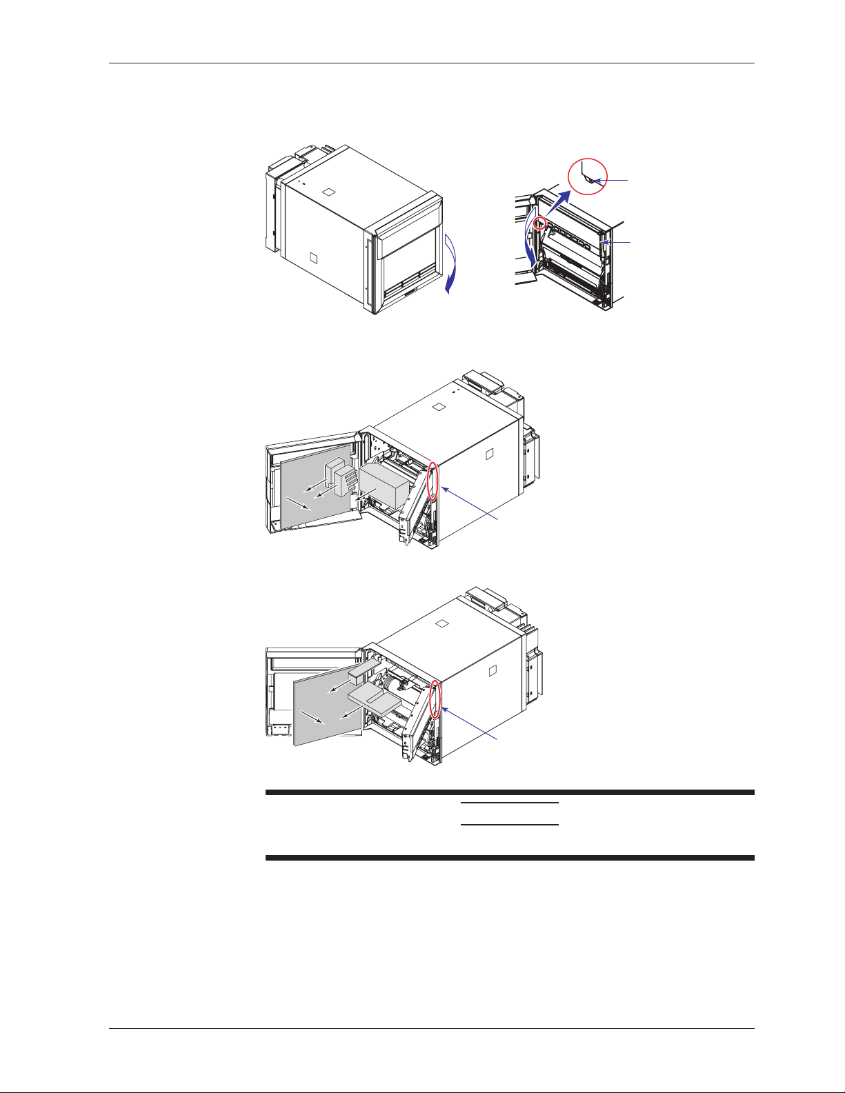
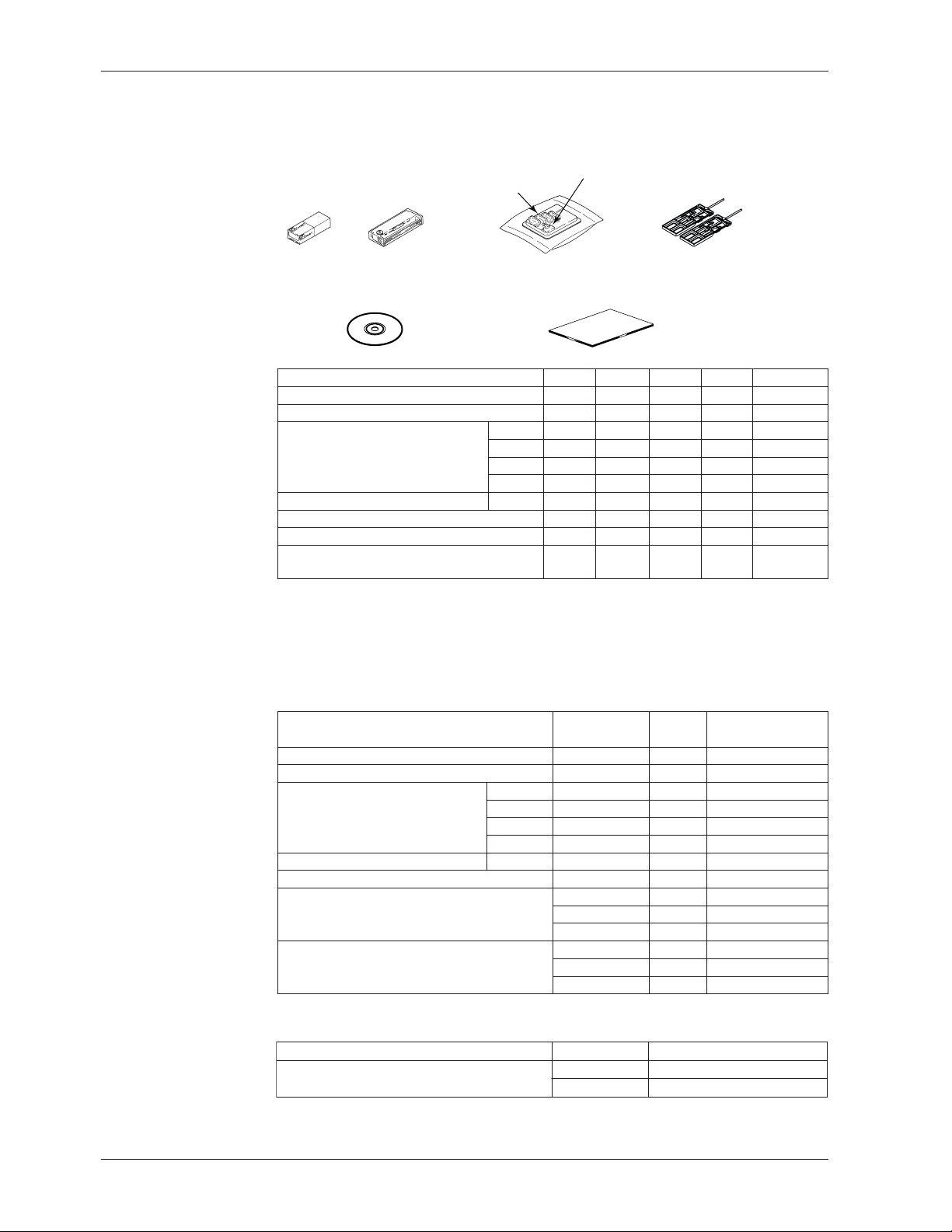
Removing the Packing Materials
Open the door, put your finger on the tab at the lower left of the display, and open the
display.
Checking the Contents of the Package
Tab on the display
Remove all packing materials.
• Pen Model
• Dot Model
Open
Open
Hinge
Display
Hinge
CAUTION
To protect the hinges, do not apply vertical force on the display.
vii
Page 10

How to Use This Manual
This user’s guide consists of the following sections.
For details on communication functions, see the RD100B/RD1800B Communication
Interface User’s Manual on the CD-ROM.
Chapter Title and Description
1 Functional Description
2 Before Using the Recorder
3 Names of Parts and Run Operations
4 Common Operations for Setting Functions and Setup Guide
5 Frequently Used Setup Operations (Setting Mode)
6 Setup Operations for Convenient Functions (Setting Mode)
7 Setup Operations for Changing/Adding Functions (Basic Setting Mode)
8 Setup Operations for Changing the Displayed Contents
9 Operations Related to the Computation Function (/M1 Option)
10 Troubleshooting
11 Maintenance
12 Specifications
Appendix Describes the printout contents.
Index
Describes the functions of the RD100B Recorder. Refer to this chapter when you
are unsure of the details of the function that you are operating.
Describes the installation and wiring procedures.
Describes the names of each part of the recorder and the daily operations.
Describes the execution modes of the recorder, basic setup operations using keys,
and provides a function setup guide.
Describes how to change the input range, alarms, chart speed, etc.
Describes the setup operations for convenient functions such as how to assign tags
to channels and how to set message strings that are to be printed.
Describes the setup operations for changing or adding functions such as setting the
recorder to detect sensor burnouts and changing the contents that are printed on the
chart paper.
Describes how to select the display type suitable for the application.
Describes all operations related to the computation function.
Describes error message and troubleshooting measures of the RD100B Recorder.
Describes periodic inspection, calibration, pen adjustment/printer carriage
adjustment, and recommended replacement period for worn parts.
Gives the specifications of the RD100B Recorder.
viii
Note
• This user’s manual covers information regarding the recorders with English as the display/
recording language (suffix code “2”).
• For the procedure of setting the display/recording language, see section 7.14, “Changing the
Display/Recording Language.”
Page 11

How to Use This Manual
Conventions Used in This Manual
Unit
K ........ Denotes 1024. Example: 768 KB (file size)
k ........ Denotes 1000.
Safety Markings
The following markings are used in this manual.
WARNING
CAUTION
Improper handling or use can lead to injury to the user or
damage to the instrument. This symbol appears on the
instrument to indicate that the user must refer to the user’s
manual for special instructions. The same symbol appears in
the corresponding place in the user’s manual to identify those
instructions. In the manual, the symbol is used in conjunction
with the word “WARNING” or “CAUTION.”
Calls attention to actions or conditions that could cause serious
or fatal injury to the user, and precautions that can be taken to
prevent such occurrences.
Calls attentions to actions or conditions that could cause light
injury to the user or damage to the instrument or user’s data,
and precautions that can be taken to prevent such occurrences.
1
2
3
4
5
6
7
Note
Subheadings
On pages that describe the operating procedures in Chapter 3 through 9, the following
symbols are used to distinguish the procedures from their explanations.
Bold characters denote keys or character strings that are displayed on the screen.
Example: Range, Unit
Procedure
Explanation
Calls attention to information that is important for proper
operation of the instrument.
Follow the numbered steps. All procedures are written with
inexperienced users in mind; depending on the operation, not
all steps need to be taken.
This subsection describes the setting parameters and the
limitations on the procedures. It does not give a detailed
explanation of the function. For details on the function, see
chapter 1.
8
9
10
11
12
App
Index
ix
Page 12

Contents
Foreword ......................................................................................................................................... i
Recorder’s Version and Functions Described in This Manual ......................................................... ii
Safety Precautions ......................................................................................................................... iii
Checking the Contents of the Package .......................................................................................... v
How to Use This Manual .............................................................................................................. viii
Chapter 1 Functional Description
1.1 Overview of the Recorder ................................................................................................ 1-1
1.2 Measuring Input Section ................................................................................................. 1-2
1.3 Alarms .............................................................................................................................. 1-7
1.4 Recording ....................................................................................................................... 1-13
1.5 Display ........................................................................................................................... 1-22
1.6 Computation Function (/M1 Option) ............................................................................... 1-24
1.7 FAIL/Chart End Detection and Output Function (/F1 Option) ........................................ 1-27
1.8 Remote Control Function (/R1 Option) .......................................................................... 1-28
1.9 Other Functions ............................................................................................................. 1-30
Chapter 2 Before Using the Recorder
2.1 Handling Precautions ....................................................................................................... 2-1
2.2 Installation ........................................................................................................................ 2-2
2.3 Input Signal Wiring ........................................................................................................... 2-5
2.4 Optional Terminal Wiring .................................................................................................. 2-9
2.5 Power Supply Wiring ...................................................................................................... 2-12
2.6 Turning ON/OFF the Power Switch................................................................................ 2-14
Chapter 3 Names of Parts and Run Operations
3.1 Names of Parts ................................................................................................................ 3-1
3.2 Installing or Replacing the Chart Paper ........................................................................... 3-4
3.3 Installing/Replacing Felt Pens or Plotter Pen (Pen Model) .............................................. 3-7
3.4 Installing/Replacing the Ribbon Cassette (Dot Model) .................................................... 3-9
3.5 Starting/Stopping the Recording .................................................................................... 3-11
3.6 Switching the Display Screen ........................................................................................ 3-12
3.7 Printing Measured Values (Manual Printout) ................................................................. 3-13
3.8 Printing the Recorder Settings ....................................................................................... 3-14
3.9 Clearing the Alarm PrinAtout Buffer ............................................................................... 3-15
3.10 Printing Messages ......................................................................................................... 3-16
3.11 Resetting the Report Data of the Periodic Printout ........................................................ 3-17
3.12 Releasing the Alarm Output (Alarm ACK Operation) ..................................................... 3-18
3.13 Activating/Releasing the Key Lock ................................................................................. 3-19
Chapter 4 Common Operations for Setting Functions and Setup Guide
4.1 Run Modes ....................................................................................................................... 4-1
4.2 Key Operations ................................................................................................................ 4-2
4.3 Menu Structure, Settings, and List of Default Values....................................................... 4-5
4.4 Function Setup Guide .................................................................................................... 4-13
Chapter 5 Frequently Used Setup Operations (Setting Mode)
5.1 Setting the Input Range ................................................................................................... 5-1
5.2 Setting the Alarm.............................................................................................................. 5-9
5.3 Setting the Unit on Scaled Channels ............................................................................. 5-12
x
Page 13

Contents
5.4 Changing the Chart Speed ............................................................................................ 5-13
5.5 Setting the Date/Time .................................................................................................... 5-14
Chapter 6 Setup Operations for Convenient Functions (Setting Mode)
6.1 Setting the Trend Recording Interval (Dot Model)............................................................ 6-1
6.2 Setting the Filter (Pen Model) .......................................................................................... 6-2
6.3 Setting the Moving Average (Dot Model) ......................................................................... 6-3
6.4 Setting Recording Zones for Each Channel (Zone Recording) ........................................ 6-4
6.5 Setting the Partial Expanded Recording .......................................................................... 6-5
6.6 Turning Trend Recording (Dot Model) and Periodic Printout ON/OFF for Each Channel 6-6
6.7 Setting Tags on Channels ................................................................................................ 6-7
6.8 Setting the Message String .............................................................................................. 6-8
6.9 Setting the Secondary Chart Speed (Remote Control Function, /R1) ............................. 6-9
6.10 Setting the Alarm Delay Duration ................................................................................... 6-10
6.11 Setting the Brightness of the Display and Internal Light ................................................ 6-11
6.12 Applying a Bias on the Measuring Input Signal ............................................................. 6-12
6.13 Setting the Date/Time When Switching between Standard Time and DST ................... 6-13
Chapter 7 Setup Operations for Changing/Adding Functions (Basic Setting
Mode)
7.1 Changing the Auxiliary Alarm Function ............................................................................ 7-1
7.2 Changing the Integration Time of the A/D Converter ....................................................... 7-4
7.3 Setting the Burnout Detection Function of Thermocouples ............................................. 7-5
7.4 Setting the RJC Function on Channels Set to TC Input ................................................... 7-6
7.5 Changing the Channel Recording Color (Dot Model) ...................................................... 7-8
7.6 Recording by Compensating for the Pen Offset along the Time Axis (Pen Model) .......... 7-9
7.7 Turning Printouts ON/OFF.............................................................................................. 7-10
7.8 Setting the Periodic Printout Interval and the Type of Measured Values to Be Printed . 7-12
7.9 Setting the Bar Graph Display Mode ............................................................................. 7-15
7.10 Setting the Key Lock Function ....................................................................................... 7-16
7.11 Enabling the Moving Average Function (Dot Model) ...................................................... 7-19
7.12 Enabling the Filter Function (Pen Model) ....................................................................... 7-20
7.13 Enabling the Partial Expanded Recording Function ...................................................... 7-21
7.14 Changing the Display/Recording Language .................................................................. 7-22
7.15 Enabling the Bias Function, Low-Cut Function, and Alarm Delay Function ................... 7-23
7.16 Changing the Time Printout Format ............................................................................... 7-25
7.17 Initializing the Settings ................................................................................................... 7-27
7.18 Assigning Functions to the Remote Control Input Terminals (/R1 Option) ..................... 7-28
7.19 Changing the Printout/Display Format of the Date ........................................................ 7-30
7.20 Changing the Temperature Unit ..................................................................................... 7-31
1
2
3
4
5
6
7
8
9
10
11
Chapter 8 Setup Operations for Changing the Displayed Contents
8.1 Key Operations for Changing the Displayed Information ................................................. 8-1
8.2 Changing the Displayed Information ................................................................................ 8-3
Chapter 9 Operations Related to the Computation Function (/M1 Option)
9.1 Starting/Stopping/Resetting the Computation .................................................................. 9-1
9.2 Setting the Computing Equation ...................................................................................... 9-2
9.3 Setting the Unit ................................................................................................................ 9-9
9.4 Setting the Constants Used in Equations ...................................................................... 9-10
9.5 Setting the Alarm............................................................................................................ 9-11
9.6 Specifying the Timer Used in Statistical Calculations (TLOG) ....................................... 9-13
9.7 Setting Recording Zones for Each Channel (Zone Recording) ...................................... 9-15
12
App
Index
xi
Page 14

Contents
9.8 Setting the Partial Expanded Recording ........................................................................ 9-16
9.9 Turning Trend Recording (Dot Model) and Periodic Printout ON/OFF
for Each Channel ................................................................................................ 9-17
9.10 Setting Tags on Channels .............................................................................................. 9-18
9.11 Setting the Alarm Delay Duration ................................................................................... 9-19
9.12 Setting the Timer Used in TLOG Computation and Periodic Printout ............................ 9-20
9.13 Changing the Channel Recording Color (Dot Model) .................................................... 9-23
9.14 Changing the Channel Assignments of Recording Pens (Pen Model)........................... 9-24
9.15 Changing the Type of Report Data Printed in Periodic Printout ..................................... 9-25
9.16 Setting the Bar Graph Display Mode ............................................................................. 9-27
9.17 Setting the Procedure Taken When the Computed Result Is in Error ............................ 9-28
Chapter 10 Troubleshooting
10.1 A List of Error Messages ................................................................................................ 10-1
10.2 Troubleshooting Flow Charts ......................................................................................... 10-4
Chapter 11 Maintenance
11.1 Periodic Inspection ......................................................................................................... 11-1
11.2 Cleaning the Recorder ................................................................................................... 11-2
11.3 Replacing the Internal Light LED ................................................................................... 11-3
11.4 Calibrating the Recorder ................................................................................................ 11-4
11.5 Adjusting the Pen Position (Pen Model) ........................................................................ 11-6
11.6 Adjusting the Dot Printing Position (Dot Model) ............................................................. 11-7
11.7 Recommended Replacement Periods for Worn Parts ................................................... 11-9
Chapter 12 Specifications
12.1 Input Specifications ........................................................................................................ 12-1
12.2 Alarm Function Specifications ........................................................................................ 12-3
12.3 Recording Function Specifications ................................................................................. 12-4
12.4 Display Function Specifications ..................................................................................... 12-7
12.5 Specifications of Optional Functions ............................................................................ 12-13
12.6 General Specifications ................................................................................................. 12-17
12.7 Dimensional Drawings ................................................................................................. 12-21
Appendix
Appendix 1 Periodic Printout and Printout Using the TLOG Timer (/M1 Option) ................. App-1
Index
xii
Page 15
Chapter 1 Functional Description
1.1 Overview of the Recorder
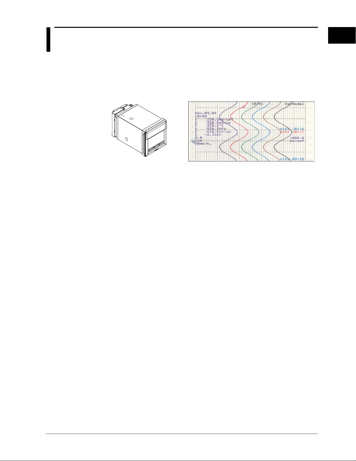
The RD100B Recorder (hereafter referred to as the recorder) can be used to assign DC
voltage, 1-5V, thermocouple, RTD, and contact or voltage ON/OFF signal to channels for
measurement. The measured results are recorded with pens or dots on a chart paper
that is fed at a constant speed. The pen model can record up to 4 channels; the dot
model can record up to 6 channels.
RD100B Recorder Recording example (dot model)
Alarms
For each channel, various alarms such as high limit alarm and low limit alarm can be
assigned to monitor the measured values. Alarm output relays can be used to output
contact signals when alarms occur (/A1, /A2, and /A3 options).
Recording
The measured results are recorded with pens or dots on a chart paper (trend recording).
The chart speed can be selected from 5 to 12000 mm/h on the pen model and 1 to 1500
mm/h on the dot model.
In addition to trend recording, various types of information can be printed or recorded on
the chart paper such as numeric measured values, alarm occurrence/release, and
predefined messages.
Also, the recorder settings can be printed.
1
Functional Description
Internal Light
A light is provided for easier viewing of the recording area of the chart paper.
Display
Measured values can be displayed numerically or using bar graphs on the large display.
Also, alarm status and chart speed can be displayed.
Communication Function
Using the Ethernet communication interface (/C7 option) or the RS-422A/485
communication interface (/C3 option), the measured values on the recorder can be
output to a PC or a PC can be used to control the recorder.
This manual does not cover the communication functions. For details on communication
functions, see the RD100B/RD1800B Communication Interface User’s Manual on the
CD-ROM.
Other Main Functions
The computation function (/M1 option) can be used to perform various computations from
four arithmetic operations to statistical calculations on 8 and 12 computation channels on
the pen model and dot model, respectively. The computed results can be recorded.
The remote control function (/R1 option) can be used to control the start/stop and other
operations of the recorder by applying contact signals to the dedicated terminals.
The FAIL/chart end detection and output function (/F1 option) can be used to output
contact signals when errors are detected on the recorder or when the chart paper runs
out.
1-1
Page 16

1.2 Measuring Input Section
Input Section
Number of Measurement Channels and Scan Interval
The recorder samples the input signals on the measurement channels at the scan
interval to obtain the measured values.
Model Number of Channels Scan Interval
1-pen model 1 125 ms
2-pen model 2 125 ms
3-pen model 3 125 ms
4-pen model 4 125 ms
Dot model 6 1 s
Input Type, Measurable Range, and Computation
The recorder can measure the following types of inputs.
Input Type Measurable Range
DC voltage DC voltage in the range of ±20 mV to ± 50 V
1-5V See “1-5V” below.
Thermocouple Temperature range corresponding to each type: R, S, B, K, E, J, T, N, W, L, U,
and WRe
RTD Temperature range corresponding to each type: Pt100Ω and JPt100Ω
ON/OFF input Contact input: Open contact is OFF (0). Closed contact is ON (1).
Voltage input: Less than 2.4 V is OFF (0). Greater than or equal to 2.4 V is ON (1)
(However, the scan interval is 2.5 s when the
integration time of the A/D converter is 100 ms.)
• 1-5V
1-5V is scaled to values in the appropriate unit to be used as measured values. Also,
the low-cut function (input less than 0% is fixed to 0 (scale left value)) can be used.
• Current Input
A shunt resistor is attached to the input terminal. The current signal is converted to a
voltage signal and measured. The measurable range is the range equivalent to the
“DC voltage” range indicated above after converting the current to the voltage signal.
Note
Three types of shunt resistors (250 Ω, 100 Ω, and 10 Ω) are available for current input (see
“Optional Accessories (Sold Separately)” on page v). For example, a 250-Ω shunt resistor is
used to convert the signal to the range of 1 to 5 V for 4 to 20 mA input.
• Range Type, Measurable Range, and Recording Span
Various “range type” are available for the different types of inputs (for example
thermocouple R). Each range type has a preset measurable range (0.0 to 1760.0°C
for thermocouple R). Measurement can be made by specifying an arbitrary range
within the measurable range as the input range. The measured values in the input
range are recorded on the chart paper. The range of measured values that are
recorded is called the recording span.
Measurable range
(Thermocouple R example)
1760.0°C
Input range or
recording span
1500.0°C (rightmost value of span)
1-2
300.0°C (leftmost value of span)
0.0°C
<Related Topics>
Setting the input range: Section 5.1
Page 17
1.2 Measuring Input Section
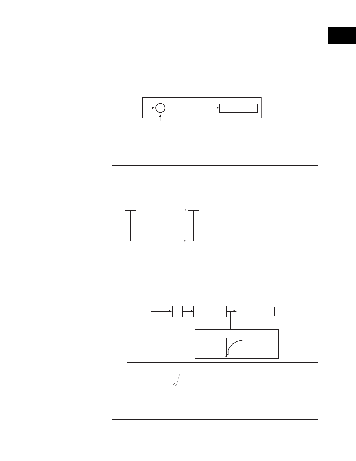
• Delta Computation
The value obtained by subtracting the measured value of another channel (called the
reference channel) from the input value of the channel set to delta computation is used
as the measured value of that channel. The reference channel must be assigned to a
channel whose channel number is less than that of the channel on which delta
computation is specified. The channel on which delta computation is specified is
automatically set to the same range type as the reference channel.
Channel set to delta computation
Input
value
–
Measured value on the reference channel
DC voltage
Measured value
Note
A channel whose input type is set to DC voltage, TC, or RTD can be designated as a
reference channel. However, channels set to scaling or square root computation cannot be
designated.
• Scaling
The input values are scaled to values in the appropriate unit to be used as measured
values.
Measured valueInput value
10 V
300.0°C
1
Functional Description
0 V −100.0°C
• Square Root Computation
When the input type is DC voltage, the square root of the input value is calculated, the
result is scaled to a value in the appropriate unit, and used as the measured value of
the channel. Also, the low-cut function (input less than a given measured value is
fixed to 0 (scale left value)) can be used.
Channel set to square root computation
Input value
√
Scaling
Measured value
Low-cut value
Measured value
Result of square
root computation
Note
The square root computation on the recorder uses the following formula.
min
V - V
F = ( F - F )
x
max
min min
where Vmin (leftmost value of span) < Vmax (rightmost value of span)
Fmin (leftmost value of scale after scaling) < Fmax (rightmost value of scale after
scaling)
Vx is the input voltage and Fx is the scaled value
x
max min
V - V
+ F
1-3
Page 18
1.2 Measuring Input Section
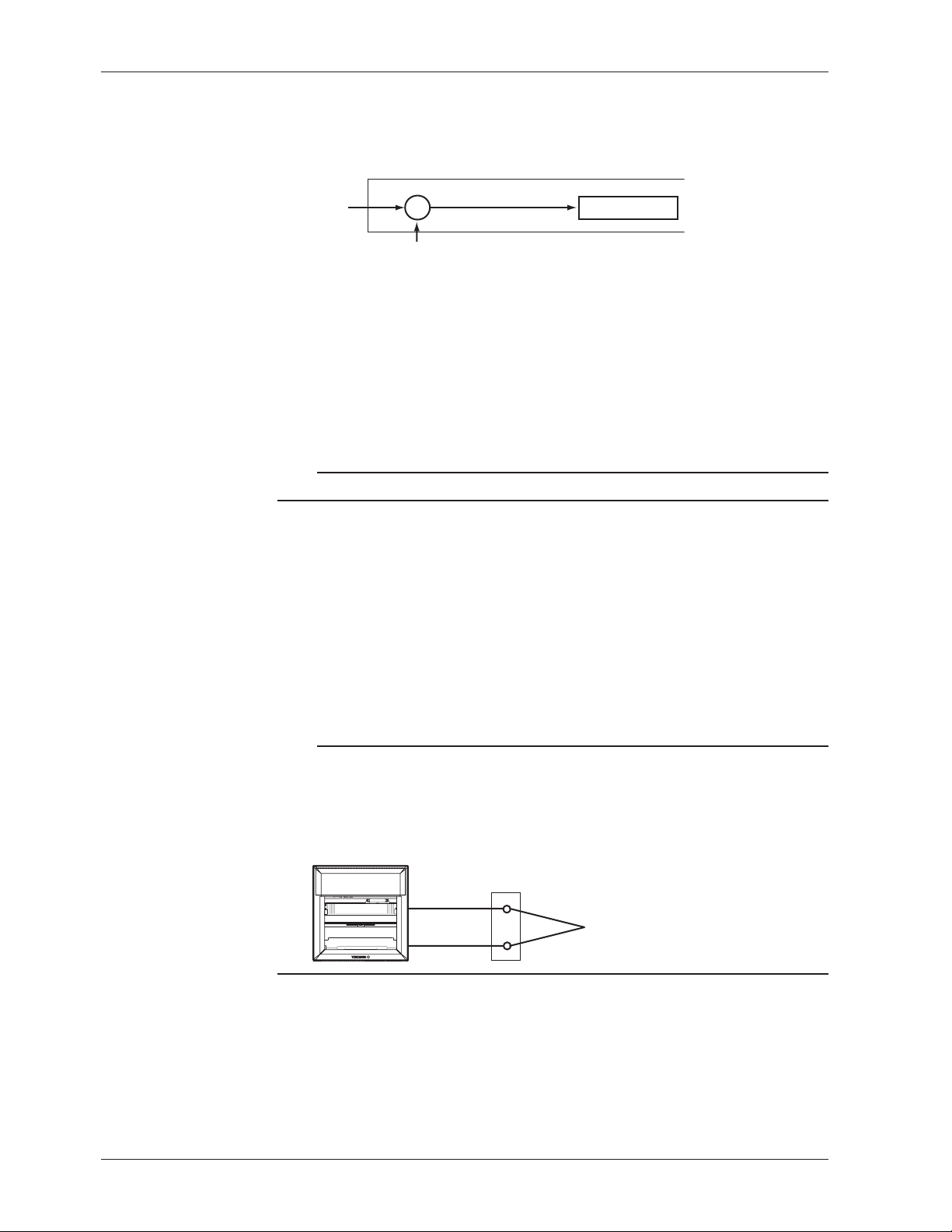
Bias
A given value (bias value) is added to the input value and used as the measured value of
that channel.
Biased channel
Input value
<Related Topics>
Setting the bias: Section 7.15 and 6.12
Burnout Detection of Thermocouples
This function makes the recording go off the scale to the right or left when the
thermocouple burns out while measuring temperature with a thermocouple. This
function can also be used on 1-5V. The burnout detection function can be set for each
channel.
By default, this function is disabled.
Note
For 1-5V, a burnout occurs when the input value is less than or equal to 0.2 V.
+
Measured value
+
Bias value
<Related Topics>
Setting the burnout detection function: Section 7.3
Reference Junction Compensation of Thermocouple Input
When measuring the temperature using a thermocouple, the reference junction
compensation on the recorder can be used. When using external reference junction
compensation, you can set the reference voltage. The reference junction compensation
can be set for each channel.
By default, the recorder is configured to use the internal reference junction compensation
function.
Note
When using external reference junction compensation, set an appropriate reference junction
compensation voltage. For example, if the reference junction temperature of the external
reference compensation is T0 °C, set the reference compensation junction voltage to the
thermoelectromotive force of the 0°C reference of T0 °C.
Example when using external reference junction compensation
Recorder
Copper wire
External reference junction compensation
(Hold the contact point of the thermocouple
and copper wire at T
Thermocouple
0
°C)
1-4
<Related Topics>
Setting the reference junction compensation function: Section 7.4
Page 19
1.2 Measuring Input Section
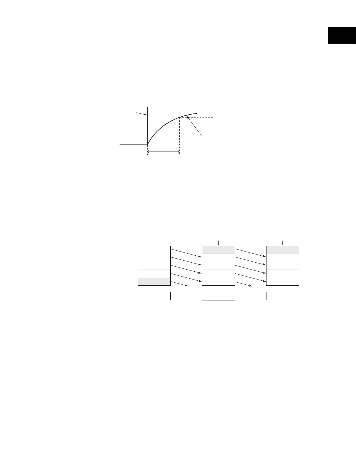
Noise Elimination from Input Signals
Filter and Moving Average
This function used to suppress the effects of noise that is riding on the signal. The pen
model and dot model are equipped with a filter function and a moving average function,
respectively. The function can be set for each measurement channel. However, it does
not operate on channels set to ON/OFF input.
• Filter (Pen Model)
The filter is a low-pass filter. The time constant can be set to 2 s, 5 s, or 10 s.
Filter result (output for a step input)
Input
2, 5, 10 s (time constant, the time it takes
to reach 63.2% of the output value)
• Moving Average (Dot Model)
The average value of the m most recent values acquired at the scan interval is used
as the measured value of the channel. The number of moving-averaged data points
(m) can be set in the range 2 to 16. The figure below shows an example indicating
the operation of the buffer for the moving average computation when the number of
moving averaged data points is set to 5.
1
Functional Description
63.2% of the output value
Output response curve
(when using the filter)
Moving
average
Buffer data for the
nth sampling time
10.0 mV
1
5.0 mV
2
0.0 mV
3
–5.0 mV
4
–10.0 mV
5
0.0 mV
Buffer data for the
n+1th sampling time
Most recent data Most recent data
15.0 mV
10.0 mV
5.0 mV
0.0 mV
–5.0 mV
Deleted
5.0 mV
<Related Topics>
Setting the filter: Section 7.12 and 6.2
Setting the moving average: Section 7.11 and 6.3
Buffer data for the
n+2th sampling time
10.0 mV
15.0 mV
10.0 mV
5.0 mV
0.0 mV
Deleted
8.0 mV
1-5
Page 20

1.2 Measuring Input Section
Integration Time of the A/D Converter
The recorder uses an A/D converter to convert the sampled analog signal to a digital
signal. By setting the integration time of the A/D converter to match the time period
corresponding to one cycle of the power supply or an integer multiple of one cycle, the
power supply frequency noise can be effectively suppressed.
The integration time of the A/D converter is selected according to the model from the
table below.
Model Integration Time of the A/D Converter
Pen model Select 16.7 ms (60 Hz), 20 ms (50 Hz), or Auto
Dot model Select 16.7 ms (60 Hz), 20 ms (50 Hz), 100 ms or Auto
• If Auto is selected, the recorder detects the power supply frequency and automatically
selects 16.7 ms or 20 ms.
• Because 100 ms is an integer multiple of 16.7 ms and 20 ms, this setting can be used
to suppress the power frequency noise for either frequency, 50 Hz or 60 Hz.
• The scan interval on the dot model is 1 s when the integration time is set to 16.7 ms or
20 ms and 2.5 s when the integration time is set to 100 ms.
<Related Topics>
Setting the A/D integration time: Section 7.2
1-6
Page 21
1.3 Alarms
This function generates an alarm when the measured data meets a certain condition.
The alarm occurrence/release can be recorded on the chart paper. The alarm status can
be displayed on the screen.
Also, alarm output relays can be used to output contact signals when alarms occur (/A1,
/A2, and /A3 options).
Alarm Types
Number of Alarm Point Marks
Up to four alarms can be set for each channel.
Alarm Conditions
The eight conditions below are available. The character inside the parentheses is the
symbol used to denote each alarm on the recorder.
• High Limit Alarm (H)
• Low Limit Alarm (L)
An alarm occurs when the input value exceeds the alarm value.
An alarm occurs when the input value falls below the alarm value.
High limit alarm
Alarm occurrence
Alarm
value
Low limit alarm
Measured
value
Alarm release
1
Functional Description
Alarm release
Measured value
Alarm occurrence
Alarm value
• Difference High Limit Alarm (h)*
An alarm occurs when the difference in the input values of two channels is greater
than or equal to the specified value.
• Difference Low Limit Alarm (l)*
An alarm occurs when the difference in the input values of two channels is less than
or equal to the specified value.
* Can be specified on channels set to delta computation.
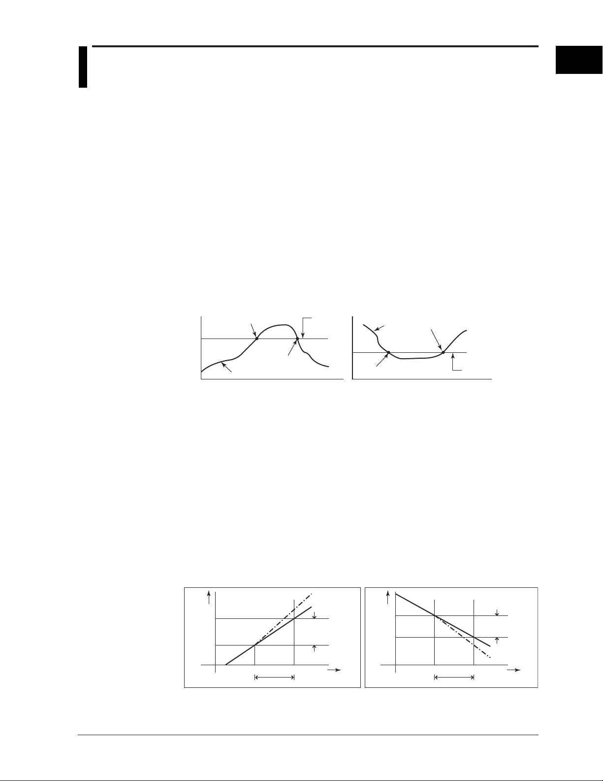
• High Limit on Rate-of-Change Alarm (R)
The rate-of-change of the measured values is checked over a certain time (interval).
An alarm occurs if the rate-of-change of the measured value in the rising direction is
greater than or equal to the specified value.
• Low Limit on Rate-of-Change Alarm (r)
The rate-of-change of the measured values is checked over a certain time (interval).
An alarm occurs if the rate-of-change of the measured value in the falling direction is
greater than or equal to the specified value.
High limit on rate-of-change alarm Low limit on rate-of-change alarm
Change in the
Measured
value
T
2
T
1
t
1
t2−t
1
Interval
measured value
Amount of change
in the setting
T2−T
||
1
t
Time
2
Measured
value
T
1
T
2
t
1
t2−t
Interval
Amount of change
in the setting
T2−T
|
t
2
1
Change in the
measured value
Time
|
1
The alarm value of the rate-of-change alarm is set using an absolute value. The
interval is derived using the following equation and set using the number of samples.
Interval = the scan interval × the number of samples
1-7
Page 22
1.3 Alarms
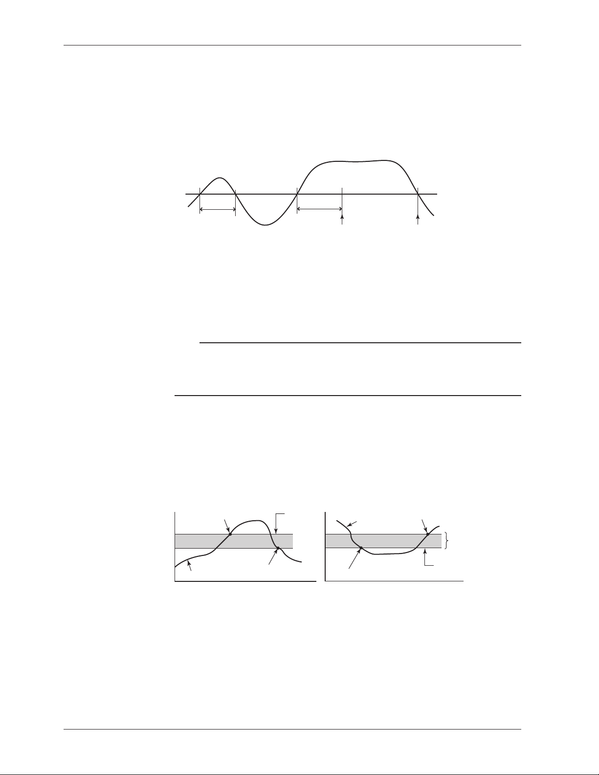
• Delay High Limit Alarm (T)
An alarm occurs when the measured value remains above the alarm value for a
specified time period (alarm delay period).
• Delay Low Limit Alarm (t)
An alarm occurs when the measured value remains below the alarm value for a
specified time period (alarm delay period).
Delay High Limit Alarm Example (T is the specified delay)
Measured value
X1 X2 X3 X4
Alarm value
T1
T
Alarm releaseAlarm occurrence
• Alarm does not occur at T1, because the time period is shorter than the specified
alarm delay period (T).
• The measured value exceeds the alarm value at time X2, and the alarm occurs at
time X3 at which the specified alarm delay period elapses (the time when the alarm
occurs is the time at X3).
• The measured value falls below the alarm value at time X4, and the alarm is
released.
Note
• The alarm detection operation is reset when a power failure occurs. The operation
restarts after the power recovers.
• If the alarm value is changed while a delay alarm is occurring, the alarm is released if the
new alarm value does not meet the alarm condition.
Alarm Hysteresis
Hysteresis can be specified to the values for activating and releasing the alarm. The
hysteresis applies only to high limit alarm (H) and low limit alarm (L). The hysteresis
width can be set in the range of 0.0% (Off) to 1.0% of the recording span in 0.1 steps.
The setting applies to all high limit alarms and low limit alarms. By default, the hysteresis
width is set to 0.5%.
High limit alarm
Alarm occurrence
Measured value
Alarm release
Alarm
value
<Related Topics>
Setting alarms: Section 5.2
Setting the alarm delay function: Section 7.15 and 6.10
Setting the alarm hysteresis: Section 7.1
Low limit alarm
Measured
value
Alarm occurrence
Alarm release
Hysteresis
(1% or less)
Alarm value
1-8
Page 23

1.3 Alarms
Alarm Indication
Alarm Recording
The alarm status can be displayed on the screen. For details on the display, see section
1.5.
Non-Hold/Hold Operation of the Alarm Indication
The alarm indication can be set to operate in the following fashion when the alarm
condition is no longer met.
• Clear the alarm indication (non-hold).
• Hold the alarm indication until the alarm ACK operation is executed (hold).
The default setting is non-hold.
HoldNon-hold
Alarm ACK Alarm ACK
or
Blinking
or
Blinking
OFF
ON
Alarm
Alarm
indication
Alarm occurrence
Alarm release
ON
OFF
OFF
<Related Topics>
Setting the non-hold/hold operation of the alarm indicator: Section 7.1
The alarm occurrence/release can be recorded on the chart paper. See section 1.4.
1
Functional Description
Alarm Output Relay (/A1, /A2, and /A3 Options)
Contact signals can be generated from alarm output relays when alarms occur. The
number of output relays is 2 (/A1), 4 (/A2), or 6 (/A3). The alarm output relays are
denoted as I01 to I06 on the recorder.
The following functions can be assigned to the alarm output relay.
Diagnosis Output
The diagnosis output can be assigned to alarm output relay I01.
The relay is activated when there is an error in the plotter operation on the pen model,
when a burnout is detected, or when there is an error in the A/D converter. Output relay
I01 is normally energized and de-energizes when an error is detected (de-energized
operation and non-hold operation).
NO C NC
Normal
NO: Normally Opened, C: Common, NC: Normally Closed
Note
If diagnosis output is enabled, I01 becomes a relay dedicated to diagnosis output.
<Related Topics>
Setting the diagnosis output: Section 7.1
NO C NC
Malfunction
NO C NC
Power-OFF
1-9
Page 24
1.3 Alarms
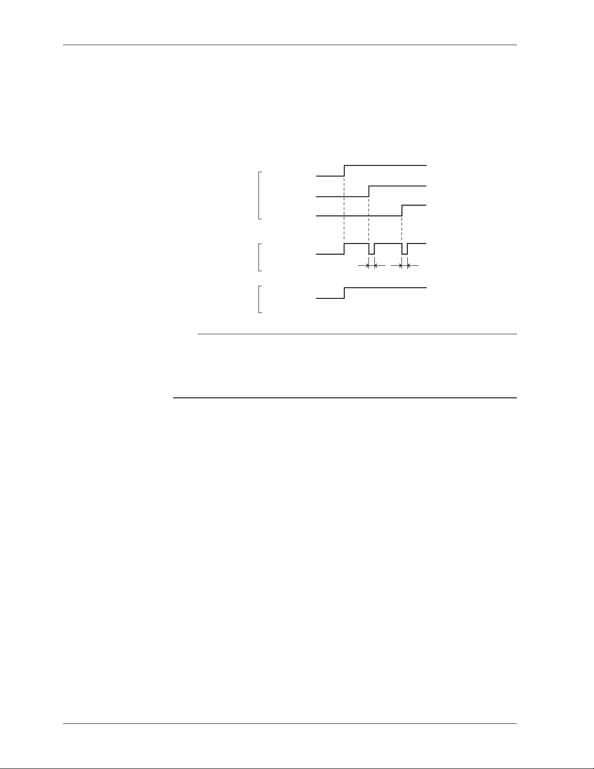
Reflash Alarm
When multiple alarms are assigned to one alarm output relay, this function notifies the
occurrence of subsequent alarms after the relay is activated by the first alarm. When
subsequent alarms occur, the output relay is released temporarily (approximately 500
ms).
The reflash alarm function is set to three output relays (I01, I02, and I03 (I01 and I02 for
the /A1 option)).
By default, the reflash alarm is disabled.
Alarm
Alarm output relay
(Reflash alarm ON)
Alarm output relay
(Reflash alarm OFF)
Channel 1
Channel 2
Channel 3
Approx. 500 ms Approx. 500 ms
Note
• If the reflash alarm is enabled, I01 to I03 are set to reflash alarm operation. In this case, I01
to I03 are set to OR operation and non-hold operation regardless of the settings specified in
“AND/OR Operation of Alarm Output Relays” and “Non-Hold/Hold Operation of Alarm Output
Relays” described below.
• If diagnosis output is enabled, I01 is set to diagnosis output.
<Related Topics>
Setting the reflash alarm: Section 7.1
1-10
Page 25

1.3 Alarms
AND/OR Operation of Alarm Output Relays
When multiple alarms are assigned to one alarm output relay, the condition for activating
the alarm output relay can be selected from the following:
• AND: Activated when all assigned alarms are occurring simultaneously.
• OR: Activated when any of the specified alarms is occurring.
Channel 01
Alarm
Channel 02
AND
Alarm output relay
OR
The alarm output relays assigned to AND operation are specified as follows: “I01 (first
relay) to Ixx (where xx is the relay number).”
The default setting is “no AND relay.”
Note
• If the reflash alarm is enabled, I01 to I03 are fixed to OR operation. Specifying AND
produces no effect.
• If diagnosis output is enabled, I01 is set to diagnosis output. Specifying AND produces no
effect.
1
Functional Description
<Related Topics>
Setting the AND operation: Section 7.1
Energized/De-energized Operation of Alarm Output Relays
You can select whether the alarm output relay is energized or de-energized when an
alarm occurs. If de-energized is selected, the status of the alarm output relay when an
alarm occurs is the same as the status that results when the power is shut down. The
setting applies to all alarm output relays.
The default setting is energized.
NO
Energize
De-energize
NO : Normally Opened, C : Common, NC : Normally Closed
C NC NO C NC NO C NC
NC
When power is
shut down
NO C NC NO C NCNO C
When alarm is
not occurring
When alarm is
occurring
Note
If diagnosis output is enabled, I01 is fixed to de-energized operation.
<Related Topics>
Setting the energized/de-energized operation of alarm output relays: Section 7.1
1-11
Page 26

1.3 Alarms
Non-Hold/Hold Operation of Alarm Output Relays
The alarm output relay can be set to operate in the following fashion when the alarm
condition is no longer met.
• Turn off the relay output (non-hold).
• Hold the relay output until the alarm ACK operation is executed (hold).
The setting applies to all alarm output relays.
The default setting is non-hold.
HoldNon-hold
Alarm
Alarm output
relay
Alarm occurrence
Alarm release
Activated
Released
Alarm
ACK
or
or
Alarm
ACK
Alarm
ACK
Note
• If the reflash alarm is enabled, I01 to I03 are fixed to non-hold operation. Specifying Hold
produces no effect.
• If diagnosis output is enabled, I01 is fixed to non-hold operation. Specifying Hold produces
no effect.
<Related Topics>
Setting the non-hold/hold operation of alarm output relays: Section 7.1
Alarm ACK Operation
The alarm acknowledge (alarm ACK) operation releases all alarm indications and relay
outputs (/A1, /A2, and /A3 options) that are activated when the alarm indication or alarm
output relay is set to hold operation. This operation can be executed from the front panel
key.
<Related Topics>
Alarm ACK operation: Section 3.12
1-12
Page 27
1.4 Recording
The recorder is capable of recording the measured values with pens or dots (trend
recording) as well as various other types of information.
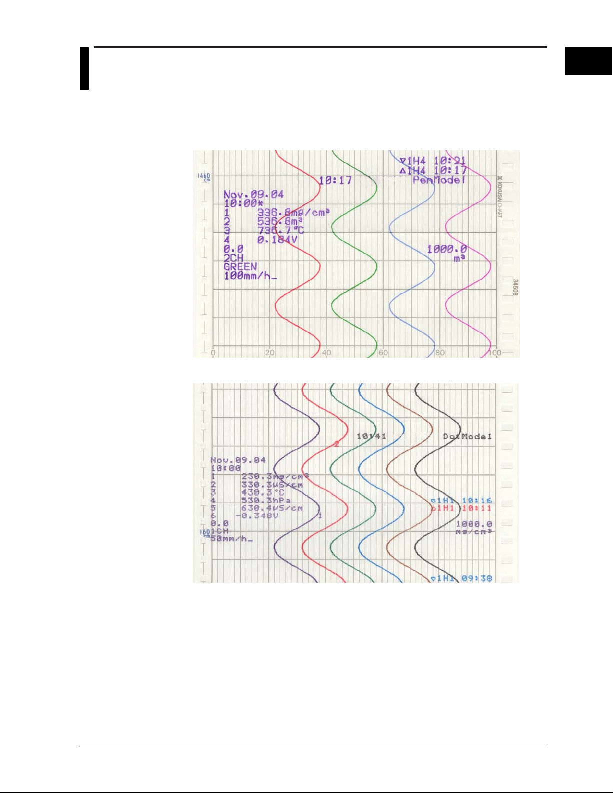
Recording Example on the Pen Model
1
Functional Description
Recording Example on the Dot Model
The recording examples may appear differently from the actual recording as a result of functional
improvements made on the recorder after this manual was written.
<Related Topics>
Starting/Stopping recording: Section 3.5
1-13
Page 28
1.4 Recording
Trend Recording
The measured values are printed within a width of 100 mm.
Recording Method (Pen Model)
• The measured value is updated every scan interval and continuously recorded.
• The recording colors in order from channel 01 are red, green, blue, and violet.
Recording Method (Dot Model)
• The most recent measured value is recorded with a dot every dot printing interval.
The dot printing interval is in the range of 10 s to 90 s. There are two recording
methods from which you can select. One method automatically adjusts the dot
printing interval according to the chart speed so that the dots do not overlap. The
other method records at the fastest dot printing interval at all times.
• The recording colors in order from channel 01 are purple, red, green, blue, brown, and
black. The recording color of each channel can be changed among these six colors.
• For each channel, trend recording can be enabled or disabled.
<Related Topics>
Setting the dot printing interval: Section 6.1
Changing the recording color: Section 7.5
Enabling/Disabling trend recording for each channel: Section 6.6
Chart Speed
On the pen model, the chart speed can be selected from 82 settings in the range of 5 to
12000 mm/h.
On the dot model, the chart speed can be set in the range of 1 to 1500 mm/h in 1-mm
steps.
The default setting is 20 mm/h.
<Related Topics>
Setting the chart speed: Section 5.4
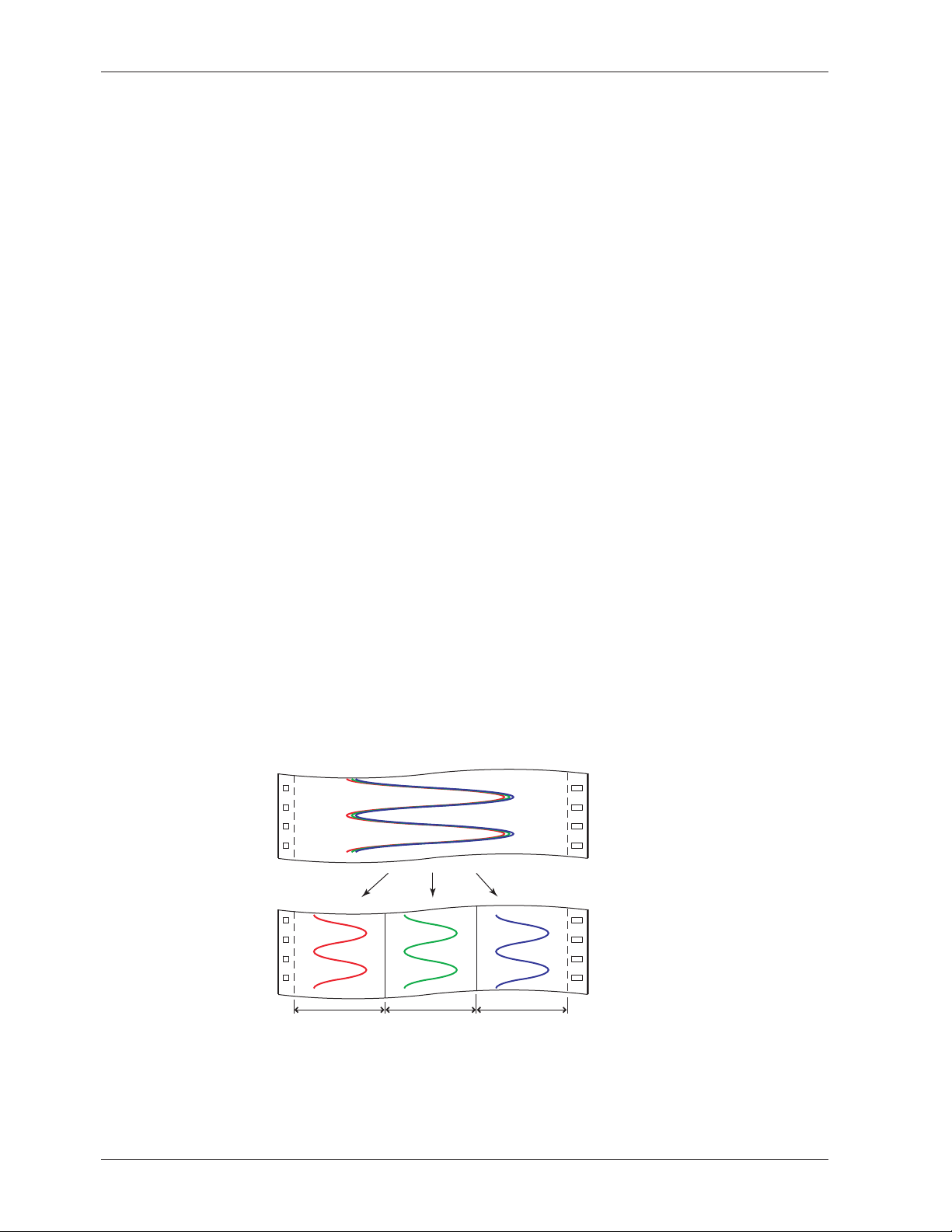
Zone Recording
A recording zone is assigned to each channel.
1-14
Zone 1 Zone 2 Zone 3
<Related Topics>
Setting the zone recording: Section 6.4
Page 29
1.4 Recording
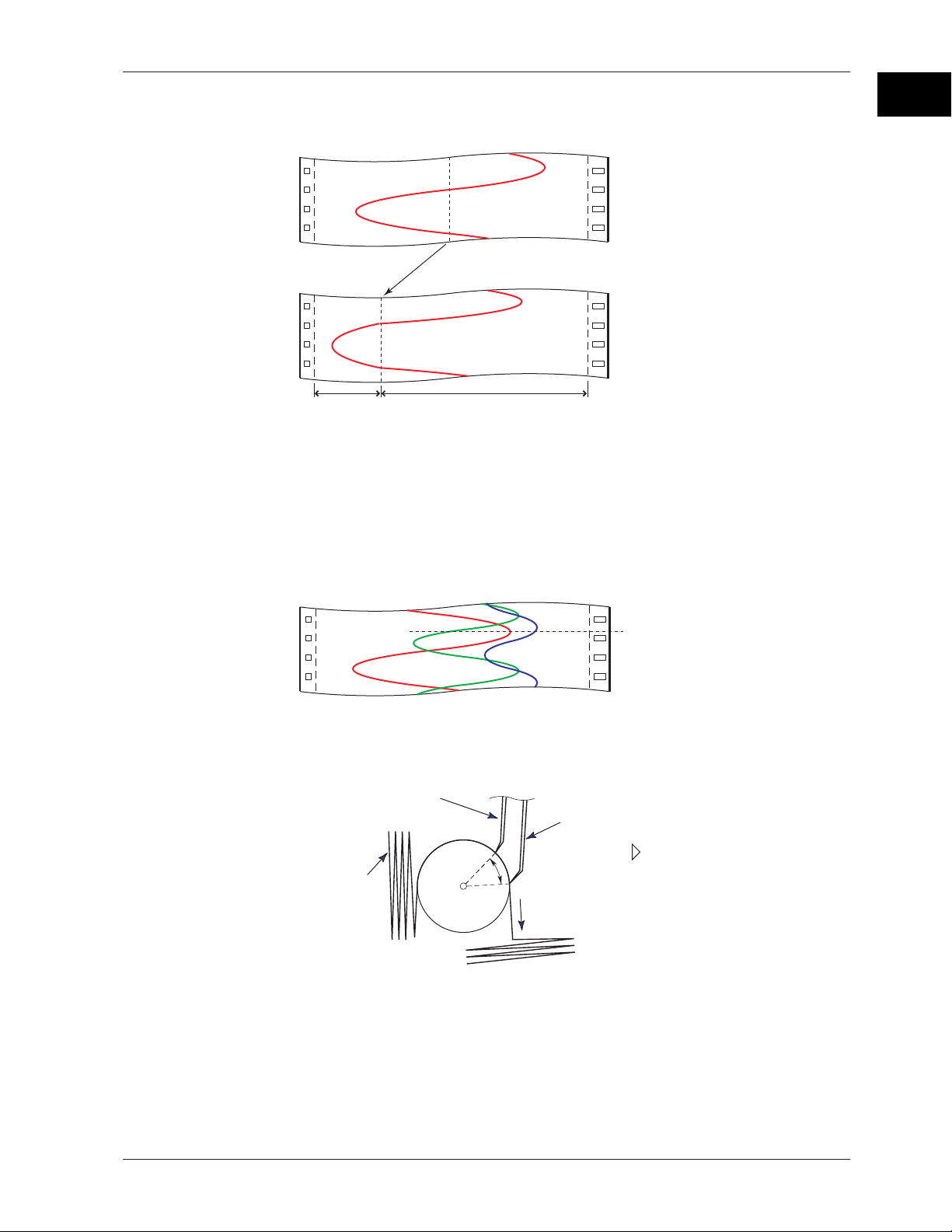
Partial Expanded Recording
This function expands a section of the recording range. By default, partial expanded
recording is disabled.
Compressed Expanded
<Related Topics>
Setting the partial expanded recording: Section 7.13 and 6.5
Pen Offset Compensation (Pen Model)
This function compensates for the pen offset (phase difference) along the time axis.
On 2-pen, 3-pen, and 4-pen recorders, there are offsets along the time axis (phase
difference) between the pens. This offset is corrected when pen offset compensation is
used.
1
Functional Description
Same time
Below is an explanation for the 2-pen model.
The recording of these two pens are offset by an amount of phase P. If pen offset
compensation is enabled, the measured values of pen 1 are stored in the memory, and
recorded when the chart paper is fed by an amount corresponding to P.
Reference pen (pen 2)
Pen 1
Recorder front panel
Chart paper
P
Chart feeding direction
By default, this function is disabled.
<Related Topics>
Setting the pen offset compensation: Section 7.6
1-15
Page 30
1.4 Recording
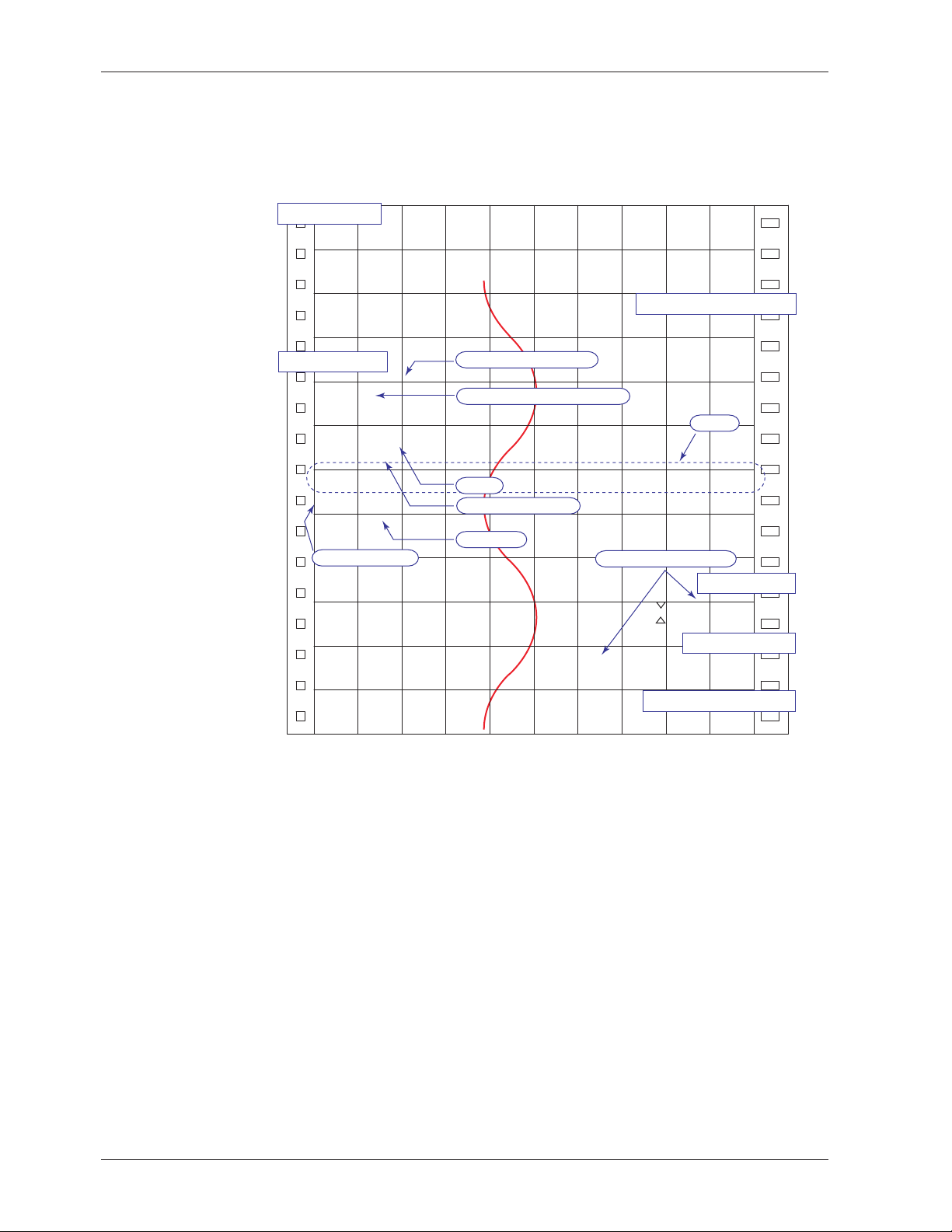
Printout
The figure below is used to explain the printout contents. The actual printout and font
are different from those illustrated in the figure. The printout positions are also slightly
different.
Printout Example on the Pen Model
Manual printout
Nov.09.04 15:00
1 223.5mg/cm
3
2 437.2µS/cm
3 H 591.6˚C 4 −0.222V
New chart speed printout
50mm/h*14:55
Periodic printout
Time tick cancel mark
Nov.09.04!
13:50*
1 218.7mg/cm
2 390.6µS/cm
Offset compensation mark
3
Scale
3 H 598.4˚C
4 d −0.222V
0.0 500.0
1CH mg/cm
RED
50mm/h_
Recording color
Alarm
Delta computation
Time tick
Buffer overflow mark
3
Alarm printout
1H3*10:09
1H3 10:05
Message printout
09:52*START#205 ABCDEF
Recording start printout
08:00*25mm/h
Time tick
The time ticks are marks that indicate the positions of the date/time on the chart paper.
Time tick cancel mark
An exclamation point (!) is printed when the periodic printout time tick was not printed at the
correct position.
1-16
<Related Topics>
Setting the channel printout (dot model)/pen color printout (pen model): Section 7.7
Setting the alarm printout, new chart speed printout, and recording start printout:
Section 7.7 and 7.16
Clearing the alarm printout buffer: Section 3.9
Setting the periodic printout: Section 6.6, 7.7, and 7.8
Executing manual print: Section 3.7
Printing messages: Section 6.8 and 3.10
Printing settings: Section 3.8
Page 31

1.4 Recording
Printout Example on the Dot Model
Manual printout
Nov.09.04 16:00
1 223.5mg/cm
3
2 437.2µS/cm
3 H 591.6˚C 4 −0.222V
5 −0.665V 6 L −0.448V
New chart speed printout
_50mm/h*14:55
Periodic printout
Nov.09.04
13:50
1 218.7mg/cm
3
Time tick
2 390.6µS/cm
3 H 598.4˚C
4 d −0.222V
5 −0.995V
6 L −0.448V
0.0 500.0
1CH mg/cm
50mm/h_
Delta computation
Alarm
Time tick
Buffer overflow mark
09:52*START#205 ABCDEF
1
Functional Description
Scale
3
Alarm printout
1H3*10:09
1H3 10:05
Message printout
Recording start printout
_08:00*25mm/h
Channel printout
Time tick
Channel Printout (Dot Model Only)
Prints the channel No. or tag by the trend recording. The channel No. or tag is printed
every approximately 25 mm on the chart paper. The channel printout can be enabled or
disabled. By default, the channel printout is enabled.
1-17
Page 32
1.4 Recording
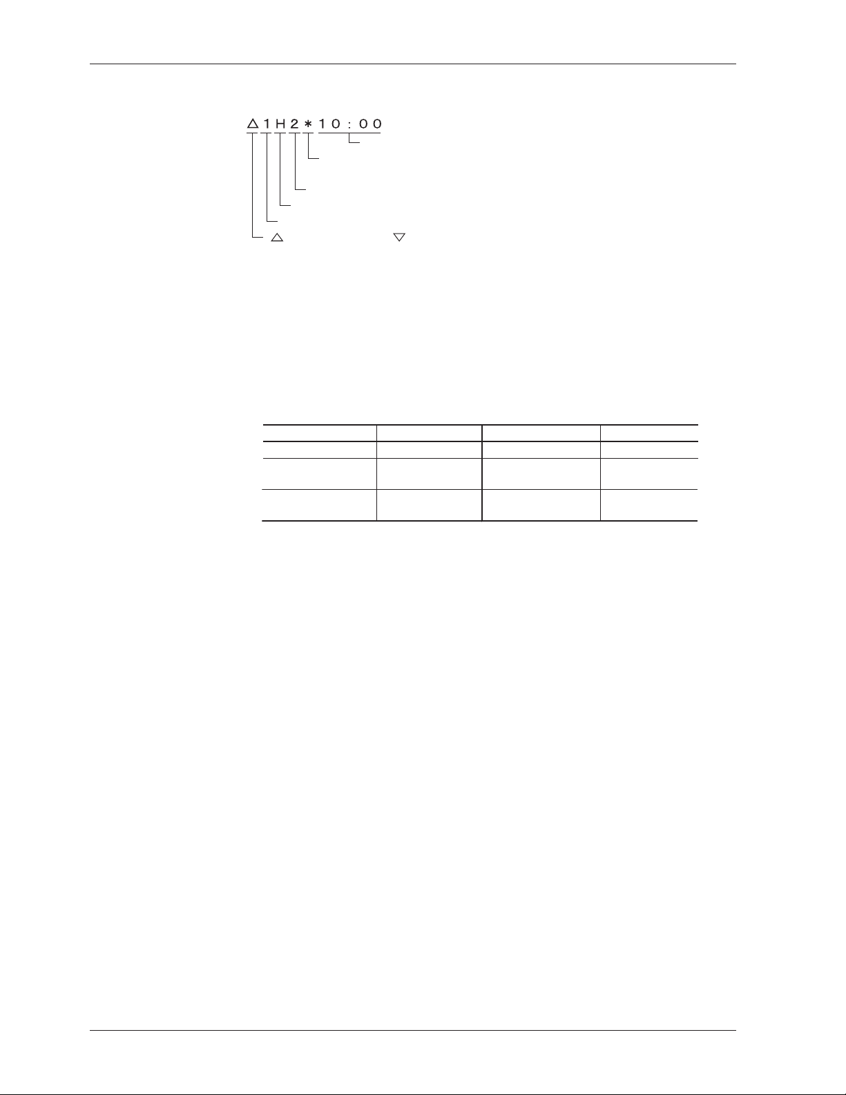
Alarm Printout
Alarm information is printed when an alarm occurs or releases.
Time of alarm occurrence/release
Indicates that there are alarms that are not
printed because the alarm printout buffer is full.
Level number
Alarm type
Channel No. or tag
: Alarm occurrence, : Alarm release
• The print condition can be set to (1) print when alarms occur and release, (2) print
only when alarms occur, or (3) do not print.
• Alarms that occur while an alarm printout is in progress are temporarily saved to the
buffer memory in a printout-wait condition. Alarms are cleared from the buffer
memory when they are printed.
• The number alarms that can be stored in the buffer is 8 and 12 on the pen model and
dot model, respectively. Alarms that occur while the buffer is full are not printed. A
buffer overflow mark is printed when there are alarms that cannot be printed because
the buffer is full.
• The time printout format can be selected.
Type
Hour:Minute
Month:Day:
Hour:Minute
Year:Month:Day:
Hour:Minute:Second
* The format of year, month, and day varies depending on the setting (see the next page).
Printout format Type Printout format
10 : 00
Nov. 09
10 : 00
Nov. 09. 2004
10 : 00 : 00
Hour:Minute:Second
Month:Day:
Hour:Minute:Second
10 : 00 : 00
Nov. 09
00 : 00 : 00
Periodic Printout
Measured values and other items are printed at the preset interval.
• Printout Contents (for details, see appendix 1)
• Date/time, time ticks (marks that indicate the positions of the date/time on the chart
paper); measured values, alarm status, scale (leftmost and rightmost values of
span) and recording color (pen model) for each channel; and chart speed can be
printed. When pen offset is being executed on the pen model, the pen offset marks
are printed. On the pen model, if a time tick is not printed at the correct position, a
time tick cancel mark (!) is printed.
• Printout of measured values and alarm status can be enabled or disabled for each
channel.
• Printout of the scale and recording colors (pen model) can be enabled or disabled.
The scale can be printed when the recording zone is greater than or equal to 40 mm.
• The measured values for each channel can be selected from the following data types.
Instantaneous value (measured value at the time of periodic printout)
Average value (average of the measured values over an interval)
Minimum value (minimum value of the measured values over an interval)
Maximum value (maximum value of the measured values over an interval)
Minimum value, maximum value, and average value
Sum value (summed value of the measured values over an interval)
• Interval
The printout interval can be set by specifying the value or set automatically in sync
with the chart speed. Periodic printout is disabled at the following chart speeds.
Pen model: Less than or equal to 9 mm/h or greater than or equal to 1600 mm/h
Dot model: Less than or equal to 9 mm/h or greater than or equal to 101 mm/h
1-18
Page 33

1.4 Recording
• Turning ON/OFF the Periodic Printout
Periodic printout can be turn ON/OFF. By default, periodic printout is enabled with the
interval synchronized to the chart speed. Also, the measured values that are printed
are the instantaneous values.
Manual Printout
Measured values and alarm status can be printed manually using the keys. When
manual printout is executed, trend recording stops and restarts when manual printout is
complete.
Message Printout
Preset messages can be printed on the chart paper using the keys. Five messages,
each within 16 characters, can be registered in advance.
• If message printout is executed while another message is being printed, the most
recent message is temporarily stored to the buffer memory in a printout-wait condition.
Messages are cleared from the buffer memory when they are printed.
• The number of messages that can be stored in the buffer is 5. If message printout is
executed when the buffer is full, the message is not printed. A buffer overflow mark is
printed when there are messages that cannot be printed because the buffer is full.
• The time printout format can be selected.
New Chart Speed Printout
• When the chart speed is changed, the time tick (dot model), the date/time of change,
and the new chart speed are printed. An asterisk (*) shows there are messages that
cannot be printed.
• The time printout format can be selected.
1
Functional Description
Recording Start Printout
When recording is started, the time tick (dot model), the time, and the chart speed can
be printed. An asterisk (*) shows there are messages that cannot be printed.
• The recording start printout can be enabled or disabled. By default, the recording
start printout is disabled.
• The time printout format can be selected.
Printout/Display Format of the Date
The printout/display format of the date can be selected from the list below. The setting
applies to all dates printed and shown on the display.
Type Printout/Display Format
Y/M/D 2005/08/31
M/D/Y 08/31/2005
D/M/Y 31/08/2005
D.M.Y 31.08.2005
M.D.Y Aug.31.2005
<Related Topics>
Setting the printout/display format of the date: Section 7.19
1-19
Page 34

1.4 Recording
Setting Printout
List or Setup List can be printed. When setting printout is executed, trend recording
stops and restarts when the printout is complete.
List contains settings such as the input range and alarm for each channel.
Setup List contains settings of basic specifications such as the alarm output relay
operation and printout method.
• Printout Example of List on the Pen Model
1-20
The printout examples may appear differently from the actual printout as a result of functional
improvements made on the recorder after this manual was written.
Page 35

1.4 Recording
• Printout Example of List on the Dot Model
1
Functional Description
The printout examples may appear differently from the actual printout as a result of functional
improvements made on the recorder after this manual was written.
1-21
Page 36

1.5 Display
Displayed Information
Main Display
The recorder is capable of displaying measured values, alarm information, and so on the
VFD (Vacuum Fluorescent Display). Using normal fonts, 17 characters × 2 lines can be
displayed. Using large fonts, 11 characters can be displayed.
Status display
There are 22 display types available. Also, different displays can be assigned to the top
and bottom sections of the main display. These display types can be registered to
screens 1 to 15 and switched during operation using the keys.
Status Display
A status display is available at the bottom of the main display. The indicators below turn
ON/OFF.
• RECORD
• ALARM 1 2 3 4 5 6
• MATH
• KEYLOCK
• CHART END
Main display
RECORD MATH CHART END ALARM 1 2 3 4 5 6KEY LOCK
This indicator turns ON when recording is started and turns OFF when stopped.
The numbers correspond to measurement channel numbers. The indicator turns ON
when an alarm occurs and turns OFF when the alarm is released.
If the alarm indication is set to hold operation, the indicator blinks when an alarm
occurs. When alarm ACK operation is performed, the indicator turns ON or OFF.
This indicator turns ON when computation on the computation function (/M1 option) is
started and turns OFF when stopped.
This indicator turns ON when key lock is enabled and turns OFF when disabled.
This indicator turns ON when the remaining amount of chart paper falls to
approximately 2 cm on models with the FAIL/chart end function (/F1 option).
Display Types
1-22
The following display types are available.
• Displays that show measured values
Measured values can be displayed numerically or using bar graphs. The channels
that are displayed can be switched automatically at constant intervals.
The bar graph displays 0 to 100% using 101 points.
0% 100%
• Displays that show alarms
• Displays that show the date/time and chart speed
• Displays that show the remote control input and alarm output relay statuses
• Displays that show the status
• System display
Different display types can be assigned to the top and bottom sections of the main display.
101 dots
Page 37

1.5 Display
Several display examples are shown below. For details on the display types, see
“Display Function Specifications” in section 12.4.
1 Channel Digital + 1 Bar Graph Display
Channel No.
UnitMeasured valueAlarm status
Bar graph
Scale
Alarm point mark
Flag Display
Flag (the number indicates the channel No.)
Scale
Alarm Status Display
Symbol indicating
an alarm
Measurement channel
1
Functional Description
Computation
channel
Channel on which an alarm is occurring
Channel on which an alarm is not occurring
Channel on which an alarm is not set
Date/Time and Chart Speed
The date format can be specified.
Date
Aug.31.2005 12000
11:26:37 mm/h
Chart speedTime
Status Display
Alarm status
<Related Topics>
Assigning display types to screens: Chapter 8
Switching displays: Section 3.6
Setting the bar graph display mode: Section 7.9
Changing the date format: Section 7.19
Setting the display brightness: Section 6.11
Displaying measured values: Section 12.4.
Remaining amount of chart paper is less than approx. 2 cm (/F1 option)
1-23
Page 38

1.6 Computation Function (/M1 Option)
Computation Function
Computing equations can be set up using measured values and other computed values
as variables in computation-dedicated channels, and the computation can be executed.
The computed result can be recorded. Computation is performed every scan interval.
Channels Dedicated to Computations
The computation-dedicated channels below can be used.
Model Number of Channels Channel Names
Pen model 8 0A, 0B, 0C, 0D, 0E, 0F, 0G, and 0J
Dot model 12 0A, 0B, 0C, 0D, 0E, 0F, 0G, 0J, 0K, 0M, 0N, and 0P
Types of Computations
In the table below, y represents the computed result. X and n represent the measured
value, a constant, etc.
Type Syntax in the Equation Description
Four arithmetic operation +, –, *, / Determines addition, subtraction, multiplication, and division.
Power ** Determines the power. y = X
Square root SQR() Determines the square root.
Absolute value ABS() Determines the absolute value.
Common logarithm LOG() Determines the common logarithm. y=log10x
Exponent EXP() Determines the exponent. y = e
Relational computation .LT., .LE., .GT., .GE., Determines <, ≤, >, or ≥ of two elements and outputs “0” or “1.”
.EQ., .NE.
Logical computation AND, OR, XOR, NOT Determines the AND (logical product), OR (logical sum),
XOR (exclusive logical sum) of two elements,
NOT (negation) of an element and outputs “0” or “1.”
TLOG computation TLOG.SUM(), TLOG. Determines the sum (SUM), the maximum (MAX),
MAX(), TLOG.MIN(), the minimum (MIN), the average (AVE),
TLOG.AVE(), and the maximum – minimum (P-P) at specified time
TLOG.P-P(), intervals. There are three timers for setting the interval.
n
x
Data That Can Be Used in Equations
In TLOG computation, the measured values of measurement channels or computed
values of computation channels can only be used. For all other computations, all of the
data types below can be used.
• Measured Values on Measurement Channels
Specified by the channel No. For channels that have scaling enabled, the scaled
values are used in the computation.
• Computed Values on Computation Channels
Specified by the channel No.
• Constants (K01 to K30)
The values assigned to K01 to K30 can be used as constants.
Range of values (maximum significant digits is 5):
–9.9999E+29 to –1.0000E–30, 0, 1.0000E–30 to 9.9999E+29
1-24
Page 39

1.6 Computation Function (/M1 Option)
• Communication Input Data (Pen model: C01 to C08, dot model: C01 to C12)
This data type is set using the communication interface (/C7 or /C3 option).
Range of values (maximum significant digits is 5):
–9.9999E+29 to –1.0000E–30, 0, 1.0000E–30 to 9.9999E+29
For the procedure of setting the communication input data, see the RD100B/RD1800B
Communication Interface User’s Guide M-4233.
• Status of the Remote Control Input Terminal (D01 to D05, /R1 option)
The status of the remote control input signal (1 or 0) can be used in the computation.
Use D01 to D05 (the number following the letter D is the remote control input terminal
number) to specify the status in the equations.
<Related Topics>
Setting the computing equation, constant, and unit: Section 9.2 to 9.4
Setting the TLOG timer: Section 9.6 and 9.12
Handing of the Unit in Computations
In computations, measured/computed values are handled as values without units. For
example, if the measured value of channel 01 is 20 mV and the measured value of
channel 02 is 20 V, the computed result of 01 + 02 is 40.
Recording Computation Channels
Trend Recording
Trend recording is possible by setting the recording span for each computation channel.
The recording span of computation channels can be set in the range of –9999999 to
99999999 excluding the decimal.
Zone recording and partial expanded recording are also possible.
1
Functional Description
Assignment of Computation Channels to the Pens (Pen Model)
Trend recording is possible by assigning computation channels to arbitrary pens. Only
display or printout is possible for measurement channels or computation channels that
are not assigned to a pen. Assignment of pens is possible only on models with the
computation function.
Pen 1 2 3 4
Channel 01 02 03 04 0A 0B 0C 0D 0E 0F 0G 0J
Measurement channels Computation channels
<Related Topics>
Changing the channel assignment of recording pens: Section 9.14
Changing the Channel Recording Color (Dot Model)
The recording colors of computation channels can be changed. The default recording
colors of channels are indicated below.
Recording color Purple Red Green Blue Brown Black
Computation channels 0A 0B 0C 0D 0E 0F
0G 0J 0K 0M 0N 0P
1-25
Page 40

1.6 Computation Function (/M1 Option)
• The Number of Channels Being Trend Recorded and the Fastest Recording
Interval
The fastest recording interval varies depending on the number of channels being
trend recorded. Only display or printout is possible on measurement channels or
computation channels that are not trend recorded.
Number of Channels Being Trend Recorded Fastest Recording Interval
6 channels or less 10 s
7 to 12 channels 15 s
13 to 18 channels 20 s
<Related Topics>
Changing the channel recording color: Section 9.13
Enabling/Disabling trend recording for each channel: Section 9.9
Printout
Various printouts can be executed in the same fashion as measurement channels.
The computed values of computation channels can be printed at constant intervals by
using the periodic printout timer or the two TLOG timers. The TLOG timers can be used
only on the computation channels. For the printout contents when printing using the
TLOG timer, see appendix 1.
<Related Topics>
Setting the periodic printout: Section 7.8, 9.6, and 9.15
Setting the printout using the TLOG timer: Section 9.6 and 9.12
Alarms
Up to 4 alarms can be assigned to each computation channel.
• The alarm types are high limit alarm (H), low limit alarm (L), delay high limit alarm (T),
and delay low limit alarm (t).
• Hysteresis can be specified to the values for activating and releasing the alarm. The
hysteresis applies only to high limit alarm (H) and low limit alarm (L). The hysteresis
width can be set in the range of 0.0% (Off) to 1.0% of the recording span in 0.1 steps.
The setting applies to all high limit alarms and low limit alarms. By default, the
hysteresis width is set to 0% (Off).
<Related Topics>
Setting alarms: Section 9.5
Setting the alarm delay function: Section 7.15 and 9.11
Setting the alarm hysteresis: Section 7.1
Display
Computation channels can be displayed on the VFD as with the measurement channels.
<Related Topics>
Setting the bar graph display mode: Section 9.16
Starting/Stopping Computation
Computation can be started or stopped using keys.
1-26
<Related Topics>
Starting/Stopping computation: Section 9.1
Page 41

1.7 FAIL/Chart End Detection and Output Function
(/F1 Option)
FAIL Output
When a failure occurs in the CPU of the recorder, a relay contact signal (1 signal) is
output. The relay is energized when the CPU is normal and de-energizes when a CPU
failure occurs. Therefore, relay output is carried out also when the power is turned OFF
(including a power failure). This relay behavior cannot be changed.
• FAIL Relay Output
1
Functional Description
Chart End Output
NO C NC
Normal
NO: Normally Opened, C: Common, NC: Normally Closed
When the remaining amount of chart paper falls to approximately 2 cm, recording is
stopped, and the relay contact signal (1 relay) is output. The relay is energized in this
case. This relay behavior cannot be changed.
NO C NC
Normal
NO: Normally Opened, C: Common, NC: Normally Closed
NO C NC
Failure
NO C NC
Chart end
NO C NC
Power-OFF
NO C NC
Power-OFF
1-27
Page 42

1.8 Remote Control Function (/R1 Option)
Specified operations can be carried out by applying remote signals (contact or open
collector signals) to the remote control input terminals.
There are five remote control input terminals. An action can be assigned to each
terminal.
µR10000 Recorder
Contact
Open collector
Assignable Functions
• Recording start/stop
• Remote input signal: Rising edge signifies start; falling edge signifies stop
• Starts/stops recording.
• Applying a rising edge signal when recording is already in progress produces no
effect. Applying a falling edge signal when recording is stopped produces no
effect.
• Chart Speed Switch
• Remote input signal: Level
• The chart paper is fed at the secondary chart speed while a level signal is applied
to the terminal. The secondary chart speed is set in advance.
• Message 1 Printout to Message 5 Printout
• Remote input signal: Trigger
• Prints message 1 to 5 on the chart paper.
• Manual Printout
• Remote input signal: Trigger
• Executes a manual printout.
• Alarm ACK
• Remote input signal: Trigger
• Alarm ACK is executed on all alarms that are occurring. This is valid only when the
alarm indication or output relay operation is set to hold.
• Internal Clock Adjustment
• Remote input signal: Trigger
• The internal clock of the recorder is adjusted to the nearest hour depending on the
time when the remote signal is applied.
Time When Signal Is Input Adjustment
00 min 00 s to 01 min 59 s Truncates the minutes and seconds.
02 min 00 s to 57 min 59 s The time is not changed.
58 min 00 s to 59 min 59 s Rounds up the minutes and seconds.
Example: 10 hours 01 min 50 s becomes 10 hours 00 min 00 s.
Example: 10 hours 59 min 50 s becomes 11 hours 00 min 00 s.
1-28
Page 43

1.8 Remote Control Function (/R1 Option)
• Computation Start/Stop
• Remote input signal: Rising edge signifies start; falling edge signifies stop
• Starts/stops the computation. This is valid only on models with the computation
function (/M1 option).
• If the computation is started, applying a rising edge signal produces no effect. If
the computation is stopped, applying a falling edge signal produces no effect.
• Computation Reset
• Remote input signal: Trigger
• The computed results of computation channels are reset. This is valid only on
models with the computation function (/M1 option) and while the computation is
stopped. For all other cases, applying the remote signal produces no effect.
Remote Signal (Edge, Trigger, and Level)
The above actions are carried out on the rising or falling edge of the remote signal
(edge), the ON signal lasting at least 250 ms (trigger), or the ON/OFF signal (level).
Rising/Falling edge Trigger Level
Rising
Falling
250 ms or more
250 ms or more
Operates at the
secondary chart speed
For contact inputs, the remote signal rises when the contact switches from open to
closed and falls when the contact switches from closed to open. For open collector
signals, the remote signal rises when the collector signal (voltage level of the remote
control terminal) goes from high to low and falls when the collector signal goes low to
high.
1
Functional Description
<Related Topics>
Assigning functions to the remote control input terminals: Section 7.18
Setting the secondary chart speed: Section 6.9
1-29
Page 44

1.9 Other Functions
Key Lock
Key lock is a function that prohibits key operations. When key lock is enabled, pressing
keys produces no effect. To release the key lock, a password is entered.
Key Lock Items
Each of the following keys can be included or excluded from the key lock function.
CHARACTER ESC/? SHIFT
RCD
MENU FEED
DISP
Keys that can be locked
In the case of the FUNC key, each function of the FUNC key can be included or
excluded from the key lock function.
FUNC key functions: Alarm ACK execution, computation start/stop, manual printout and
<Related Topics>
Setting the key lock function: Section 7.10
Using the key lock function: Section 3.13
FUNC
1
MENU
CH UP
setting printout, message printout, printout buffer clear, resetting of
the periodic printout report data (the average, etc.), and pen
replacement (pen model), ribbon cassette replacement (dot model)
Language
DST
Temperature Unit
The display and recording language can be set to English or Japanese.
<Related Topics>
Changing the language: Section 7.14
If the recorder is used in a region that has DST, time can be switched automatically
between DST and standard time by setting the date/time when switching from the
standard time to DST and the date/time when switching back from DST to standard time.
When switching from standard time to DST, the clock is set ahead by 1 hour. When
switching back from DST to standard time, the clock is set back by 1 hour.
<Related Topics>
Using the DST: Section 6.13
The temperature unit can be set to Celsius or Fahrenheit. The setting applies to all
channels.
<Related Topics>
Changing the temperature unit: Section 7.20
1-30
Page 45

Chapter 2 Before Using the Recorder
2.1 Handling Precautions
This section describes the precautions to be taken when using the recorder. Read this
section before use.
Handling Precautions
• Use care when cleaning the recorder, especially any plastic parts. When cleaning,
• Keep electrically charged objects away from the recorder as this may cause
• Do not apply volatile chemicals to the door glass, display, panel keys, etc. Do not
• When not in use, make sure to turn OFF the power switch.
• If there are any symptoms of trouble such as strange odors or smoke coming from the
2
Before Using the Recorder
wipe using a dry soft cloth. Do not use chemicals such as benzene or thinner, since
these may cause discoloring and deformation.
malfunction.
allow rubber and vinyl products to remain in contact with the recorder for long periods
of time. This may damage the recorder.
recorder, immediately turn OFF the power switch and the power supply source. Then,
contact OMEGA.
2-1
Page 46

2.2 Installation
Installation Location
Install the recorder indoors in a location that meets the following conditions. See also
the normal operating conditions described in section 12.6, “General Specifications.”
• Instrument Panel
The recorder is designed for panel mounting.
• Well-Ventilated Location
To prevent overheating, install the recorder in a well-ventilated location.
For the panel cut dimensions when arranging multiple recorders, see page 2-4.
Follow the panel cut dimensions providing adequate space between instruments
when other instruments are arranged on the panel.
• Minimum Mechanical Vibrations
Choose an installation location with the minimum mechanical vibration.
Installing the recorder in a location with large mechanical vibration not only causes
adverse effects on the mechanism but also may hinder normal recording.
• Horizontal
Install the recorder horizontally (However, the recorder can be inclined up to 30
degrees backwards for panel mounting).
Note
• Condensation may occur if the recorder is moved to another place where both the ambient
temperature and humidity are higher, or if the temperature changes rapidly. In addition,
measurement errors will result when using thermocouples. In this case, let the recorder
adjust to the new environment for at least one hour before using it.
• The chart paper may be adversely affected by a rapid change in the ambient temperature and
humidity.
Do not install the instrument in the following places.
• Outdoors
• In direct sunlight or near heat sources
Install the recorder in a place with small temperature fluctuations near room
temperature (23°C). Placing the recorder in direct sunlight or near heat appliances
can cause adverse effects on the internal circuitry.
• Where an excessive amount of soot, steam, moisture, dust, or corrosive gases
are present
Soot, steam, moisture, dust, and corrosive gases will adversely affect the recorder.
Avoid such locations.
• Near Strong Magnetic Field Sources
Do not bring magnets or instruments that produce electromagnetic fields close to the
recorder. Operating the recorder in strong magnetic fields can cause errors in the
measurements.
2-2
Page 47

Installation Procedure
The recorder should be mounted on a steel panel of thickness 2 mm to 26 mm.
2.2 Installation
1. Insert the recorder from the front side of the panel.
2. As shown in the figure below, mount the recorder to the panel using the
mounting brackets that come with the package.
• Use two brackets to support the top and bottom or the left and right sides of
the case. (Remove the seal that is covering the holes for the mounting
brackets beforehand.)
• The proper torque for tightening the mounting screws is 0.7 to 0.9 Nm.
• Mount the recorder to the panel according to the procedure below.
• First, attach the two mounting brackets and temporarily fasten the
attachment screws.
• Next, fix the recorder in place by tightening the attachment screws with the
appropriate torque. When the recorder is approximately perpendicular to
the panel as you fasten the screws, press the mounting bracket against the
case so that they are in contact with each other.
2
Before Using the Recorder
Screw temporarily
Tightening the screws too much can deform the case or damage the bracket.
Fix in place
Panel
Case
Mounting bracket
Attachment screw
(The figure shows the case when the mounting
brackets are used on the top and bottom of the case.)
Panel
Mounting bracket
Front
CAUTION
In contact
with each other
Torque driver
(flat blade)
Attachment screw
2-3
Page 48

2.2 Installation
151.5 (5.96)
144 (5.67)
External Dimensions of the Recorder
Unit: mm (approx. inch)
Unless otherwise specified, tolerance is ±3%
(however, tolerance is ±0.3 mm when below 10 mm).
220 (8.66)
(1.08) 27.5
144
(5.67)
151.5
(5.96)
178 (7.01)
Mounting panel
thickness
2 to 26
136.5
(5.37)
(Dimensions before attaching
9.4
the mounting bracket)
(0.37)
+2
0
Single-Unit Mounting
+2
0
137
(5.39)
137
(5.39)
Panel Cutout
+2
0
+2
0
137
(5.39)
Side-by-Side Mounting (horizontally)
+2
0
L
Units
L (mm)
2 282
3
4
5
6
7
8
9
10
n
426
570
714
858
1002
1146
1290
1434
(144xn)-6
Attach the mounting brackets to the top and
bottom when mounting the recorders side-by-side
horizontally or right and left when mounting the
recorders side-by-side vertically.
Unit: mm (approx. inch)
Unless otherwise specified, tolerance is ±3%
(however, tolerance is ±0.3 mm when below 10 mm).
175 min.
(6.89)
(Dimensions after attaching
7.5
the mounting bracket)
(0.30)
Side-by-Side Mounting
(vertically, max. 3 units)
137
(5.39)
175 min.
(6.89)
+2
0
+2
0
L
2-4
Page 49

2.3 Input Signal Wiring
General Precautions to Be Taken While Wiring
To prevent the possibility of electric shock when wiring, make sure that the
power supply source is turned OFF.
• If a strong tension is applied to the cable wired to the recorder, the terminals of
the recorder and/or the cable can be damaged. In order to prevent tension from
being applied directly on the terminals, fasten all wiring cables to the rear of the
mounting panel.
• Do not apply a voltage exceeding the following value to the input terminals as
this may damage the recorder.
• Maximum input voltage
Voltage range less than or equal to 200 mVDC, TC, RTD, and DI: ±10 VDC
Ranges other than those listed above: ±60 VDC
• Maximum common-mode voltage
±60 VDC (under measurement category II conditions)
• The recorder is an INSTALLATION CATEGORY II product.
2
Before Using the Recorder
WARNING
CAUTION
Precautions to Be Taken While Wiring
Take the following precautions when wring the input signal cables.
It is recommended that crimp-on lug with insulation sleeves (designed for 4-mm
screws) be used when connecting the input/output signal wires to the terminals.
However, this does not apply clamped terminals (/H2).
Crimp-on lug with insulation
sleeves (for 4 mm screws)
For clamped terminals (/H2), the following wire is recommended.
• Conductive cross-sectional area for single wire: 0.14 mm2 to 1.5 mm2, stranded wire:
0.14 mm
• Length of the stripped section of the wire: Approx. 5 mm
Take measures to prevent noise from entering the measurement circuit.
• Move the measurement circuit away from the power cable (power circuit) and ground
circuit.
• It is desirable that the object being measured does not generate noise. However, if
this is unavoidable, isolate the measurement circuit from the object. Also, ground the
object being measured.
• Shielded wires should be used to minimize noise caused by electrostatic induction.
Connect the shield to the ground terminal of the recorder as necessary (make sure
you are not grounding at two points).
• To minimize noise caused by electromagnetic induction, twist the measurement circuit
wires at short, equal intervals.
• Make sure to earth ground the protective ground terminal through minimum resistance
(less than 100 Ω).
2
to 1.0 mm
2
2-5
Page 50

2.3 Input Signal Wiring
When using internal reference junction compensation on the thermocouple input,
take measures to stabilize the temperature at the input terminal.
• Always use the terminal cover.
• Do not use thick wires which may cause large heat dissipation (cross sectional area of
2
0.5 mm
or less recommended).
• Make sure that the ambient temperature remains reasonably stable. Large
temperature fluctuations can occur if a nearby fan turns ON or OFF.
Connecting the input wires in parallel with other devices can cause signal
degradation, affecting all connected devices.
If you need to make a parallel connection, then
• Turn the burnout detection function OFF.
• Ground the instruments to the same point.
• Do not turn ON or OFF another instrument during operation. This can have adverse
effects on the other instruments.
• RTDs cannot be wired in parallel.
Arrangement of the Measuring Input Terminals
A terminal cover is screwed in place on the measuring input terminal block on the rear
panel. A label indicating the terminal arrangement is affixed to the cover.
Measuring input terminal block
Terminal cover
attachment screws
Pen Model
b
+/A
–/B
Channel 1
Channel 2
Channel 3
Channel 4
Screw input terminal Clamped input terminal
Channel 2
Channel 4
+/A
–/B
b
(/H2 option)
–/B
b
+/A
Channel 1
Channel 3
2-6
Page 51

Dot Model
b
–/B
2.3 Input Signal Wiring
+/A
Channel 1
Channel 2
Channel 3
Channel 4
Channel 5
Channel 6
Screw input terminal Clamped input terminal
Channel 2
Channel 4
Channel 6
+A
–/B
b
(/H2 option)
–/B
b
1. Turn OFF the recorder and remove the terminal cover.
2. Connect the signal wires to the terminals.
Screw input terminal
Signal wire
Crimp-on lug with
insulation sleeves
Signal wire
Philips
screwdriver
Clamped input terminal
+/A
Channel 1
Channel 3
Channel 5
Flat-blade
screwdriver
2
Before Using the Recorder
Note
Input signal wires of diameter less than or equal to 0.3 mm may not be secured firmly for
clamped terminals (/H2). Fold over the conducting section of the wire, for example, to make
sure that the wire is securely connected to the clamped terminal.
3. Replace the terminal cover and fasten it with screws.
The proper torque for tightening the screws is 0.6 N-m.
2-7
Page 52

2.3 Input Signal Wiring
Measuring Input Wiring
Thermocouple input Resistance temperature detector input
–/Bb +/A –/Bb +/A
Extension leadwire
DC voltage input, 1-5V input,
and ON/OFF input
–/Bb +/A –/Bb +/A
Leadwire resistance:
10 Ω max./wire. The resistance
of the three wires should be
equal.
DC current input
Shunt resistor
–
DC voltage
1-5V
++
Example: For a 4 to 20 mA
input, a shunt resistor of
250 Ω ± 0.1% can be used to
convert to 1-5V input.
–
DC current
ON/OFF
Note
RTD input terminals A and B on the dot model are isolated on each channel. Terminal b is
shorted internally across all channels. However, for 3 legs isolated RTDs (/N2 option), input b
is also isolated for each channel.
b
B
A
2-8
Page 53

2.4 Optional Terminal Wiring
General Precautions to be Taken While Wiring the Input/Output Signal Wires
WARNING
• To prevent electric shock while wiring, ensure that the power supply source is
turned OFF.
• If a voltage of more than 30 VAC or 60 VDC is to be applied to the output
terminals, use ring-tongue crimp-on lugs with insulation sleeves on all terminals
to prevent the wires from slipping out when the screws become loose.
Furthermore, use double-insulated wires (dielectric strength of 2300 VAC or
more) for the signal wires on which a voltage of more than 30 VAC or 60 VDC is
to be applied. For all other wires, use basic insulated wires (dielectric strength
of 1390 VAC). To prevent electric shock, attach the terminal cover after wiring
and make sure not to touch the terminals.
Crimp-on lug with insulation sleeves
(for 4 mm screws)
CAUTION
• To prevent fire, use signal wires having a temperature rating of 70°C or more.
• If a strong tension is applied to the cable wired to the recorder, the terminals of
the recorder and/or the cable can be damaged. In order to prevent tension from
being applied directly on the terminals, fasten all wiring cables to the rear of the
mounting panel.
2
Before Using the Recorder
Arrangement of the Optional Terminals
As shown in the figure below, the optional terminal block is located on the rear panel.
The optional terminal block is provided on the recorder when an option that requires
input/output is installed such as the alarm output relay (/A1, /A2, or /A3 option), FAIL/
chart end output (/F1 option), and remote control function (/R1 option). A terminal cover
is screwed in place on the optional terminal block. A label indicating the terminal
arrangement is affixed to the terminal block.
Terminal cover
attachment screws
Optional terminal block
2-9
Page 54

2.4 Optional Terminal Wiring
/A1
NO C NC
NO C
/A2
NO C NC
NO C NC
NO C NC
NO C
/A3
NO C NC
NO C NC
NO C NC
NO C NC
NO C NC
NO C
NC
NC
NC
I01
I02
I01
I02
I03
I04
I01
I02
I03
I04
I05
I06
/A1/F1 /A1/R1
NO C NC
NO C
NO C NC
NO C NC
NC
I01
I02
CE
FAI L
NO C NC
NO C
(/F1)
123
45C
/A2/F1 /A2/R1
NO C NC
NO C NC
NO C NC
NO C
NO C NC
NO C NC
NC
I01
I02
I03
I04
CE
FAI L
NO C NC
NO C NC
NO C NC
NO C
(/F1)
123
45C
/A3/R1 /F1
NO C NC
NO C NC
NO C NC
NO C
NO C NC
NO C NC
123
45C
I01
I02
I03
NC
I04
I05
I06
NO C NC
NO C
(/R1) (/R1)
/A1/F1/R1
I01
NC
I02
(/R1) (/R1)
NO C NC
NO C
NO C NC
NO C NC
123
45C
/A2/F1/R1
I01
I02
I03
NC
I04
(/R1) (/R1)
NO C NC
NO C NC
NO C NC
NO C
NO C NC
NO C NC
123
45C
/R1
CE
(/F1)
NC
FAI L
123
45C
NC
NC
I01
I02
CE
FAI L
I01
I02
I03
I04
CE
FAI L
(/F1)
(/F1)
2-10
/F1/R1
NO C NC
NO C
NC
123
45C
CE
FAI L
(/R1)
(/F1)
CE: Chart end
Alarm Output Relay Terminals and FAIL/Chart End Output Relay Terminals
NC (Normally Closed), C (Common), NO (Normally Opened)
Remote Control Input Terminals
1 to 5 (remote control input terminals), C (Common)
Alarm output terminals correspond to I01 to I06 in the alarm output relay settings.
Remote control input terminals 1 to 5 correspond to numbers 1 to 5 in the remote control
input settings.
Page 55

Wiring Procedure
2.4 Optional Terminal Wiring
1. Turn OFF the recorder and remove the terminal cover.
2. Connect the input signal wires to the terminals.
2
Before Using the Recorder
Philips
screwdriver
Crimp-on lug with
insulation sleeves
3. Replace the terminal cover and fasten it with screws.
The proper torque for tightening the screws is 0.6 N-m.
Alarm output
FAIL/chart end output
Relay contact output
C
NO
NC
Remote control input
Relay contact input
(Voltage-free contact)
123
45
C
Transistor input
(Open collector)
123
45
Note
To reduce noise, use a shielded cable for the wiring of the remote control input terminals.
Connect the shield to the ground terminal of the recorder.
• Relay Contact Output Specifications
Output type: Relay
Contact rating: 250 VAC (50/60 Hz)/3 A, 250 VDC/0.1 A (resistive load)
Dielectric strength: 1500 VAC at 50/60 Hz for one minute (between output
terminals and the ground terminal)
• Relay Contact Input/Transistor Input Specifications
Input signal: • Voltage-free contact: Contact closed at 200 Ω or less and
contact open at 100 kΩ or greater
• Open collector: 0.5 V or less (30 mADC) when turned ON,
leakage current of 0.25 mA or less when turned OFF
Input format: Photocoupler isolation (shared common)
Dielectric strength: 500 VDC for one minute between input terminals and the
ground terminal
C
2-11
Page 56

2.5 Power Supply Wiring
Precautions to Be Taken While Wiring the Power Supply
Make sure to follow the warnings below when wiring the power supply. To prevent
electric shock and damage to the recorder, observe the following warnings.
WARNING
• To prevent electric shock when wiring, ensure the main power supply is turned
OFF.
• To prevent the possibility of fire, use 600 V PVC insulated wire (JISC3307) or an
equivalent wire for power wiring.
• Make sure to earth ground the protective earth terminal through a grounding
resistance less than 100 Ω before turning ON the power.
• Use crimp-on lugs (designed for 4 mm screws) for power and ground wiring
termination.
• To prevent electric shock, make sure to close the transparent cover for the
power supply wires.
• Make sure to provide a power switch (double-pole type) on the power supply
line in order to separate the recorder from the main power supply. Put an
indication on this switch as the breaker on the power supply line for the recorder
and indications of ON and OFF.
Switch specifications
Rated power current: 1 A or more
Rated rush current: 60 A or more
Use a switch complied with IEC 60947-1, 3.
• Connect a fuse between 2 A and 15 A in the power supply line. Use a fuse
approved by CSA (for the use in North America) or VDE (for the use in Europe).
• Do not add a switch or fuse to the ground line.
2-12
Use a power supply that meets the following conditions:
Item Power Supply Specifications
Rated supply voltage 100 to 240 VAC
Allowable power supply voltage range 90 to 132/180 to 264 VAC
Rated supply voltage frequency 50/60 Hz
Allowable power supply frequency range 50/60 Hz±2%
Maximum power consumption Pen model: 40 VA, dot model: 40 VA
Note
Do not use a supply voltage in the range 132 to 180 VAC, as this may have adverse effects
on the measurement accuracy.
Page 57

Wiring Procedure
2.5 Power Supply Wiring
The power supply terminals and a protective ground terminal are located on the rear
panel.
1. Turn OFF the recorder and open the transparent power terminal cover.
Power terminal block
Screw for fixing the power
terminal cover in place
Power terminal cover
Open
2. Wire the power cord and the protective ground cord to the power supply
terminals.
Use ring-tongue crimp-on lugs (designed for 4 mm screws).
2
Before Using the Recorder
L
N
Philips screwdriver
Crimp-on lug with insulation sleeves
Power cord
Protective ground cord
3. Replace the power terminal cover, and fasten it with screws.
The proper torque for tightening the screws is 0.6 N-m.
2-13
Page 58

2.6 Turning ON/OFF the Power Switch
CAUTION
Check the following points before turning ON the power switch.
• The power cord/wires are connected correctly to the recorder.
• The recorder is connected to the correct power supply (see section 2.5).
The power switch is located inside the door at the lower right.
The power switch is a push button. Press once to turn it ON and press again to turn it
OFF.
When the power switch is turned ON, a self-diagnosis program runs for a few seconds,
and the recorder is ready for operation.
Note
• If the input wires are connected in parallel with other devices, do not turn ON/OFF the power
switch of the recorder or another device during operation. This can have adverse effects on
the measured values.
• If nothing is displayed when the power switch is turned ON, turn OFF the power switch and
check the points listed above one more time. After checking the points, turn ON the power
switch again. If the unit still does not work, it is probably malfunctioning. Contact OMEGA for
repairs.
• If an error message is displayed on the screen, take measures according to the description in
chapter 10, “Troubleshooting.”
• Turn ON the power switch, let the recorder warm up for at least 30 minutes, and then start the
measurements.
Checking the Date/Time
The date/time is shown on the display when the
correct the date/time, see the reference indicated below.
<Related Topics>
Setting the date/time: See section 5.5
DISP
key is pressed several times. To
2-14
Page 59

Chapter 3 Names of Parts and Run Operations
3.1 Names of Parts
Front
Display and key panel
Hold the tab at the lower
left and pull to open.
Door
Name plate
The model name is written
on the name plate.
3
Names of Parts and Run Operations
Tag plate
Used to write
channel names.
Pen model Dot model
Recording pen
Records the measured value.
Chart cassette
Holds the chart paper.
Plotter pen
Prints various types
of information.
Power switch
Turns ON/OFF the power each
time the switch is pressed.
Display and key panel (see the next page)
There is an internal light on the bottom section
of the display and key panel. It lights up the
recording area of the chart paper.
Mounting hole
There is one hole on each of the
top, bottom, left, and right panels.
The hole is covered with a seal.
Ink ribbon
Six-color ink.
Printer carriage
Records measured values
and prints various types of
information.
3-1
Page 60

3.1 Names of Parts
Display and Key Panel
Status display
Displays the following information.
RECORD Illuminates while recording measured values.
KEY LOCK Illuminates when key lock is enabled.
MATH Illuminates when computation on the computation function (/M1 option)
is in progress.
CHART END Illuminates when the chart paper is out (/F1 option).
ALARM 1 to 6 Illuminates when an alarm is occurring on channels 1 to 6.
Main display
Displays the measured values. Also, displays the setup screen when
setting functions.
KEY LOCK
RECORD MATH CHART END ALARM
CHARACTER
RCD
MENU FEED
DISP
FUNC
ESC/?
1
MENU
1 2 3 4 5 6
SHIFT
CH UP
Seven keys are available.
For all keys except RCD, functions marked above the keys are enabled when
setting functions or when the FUNC key or the DISP MENU key is pressed.
<While setting functions, when the FUNC key/DISP MENU key is pressed>
CHARACTER Key: Changes the character type when entering a character. Press
this key while holding down the SHIFT key to switch the character type in reverse
order.
UP/DOWN Key: Switches the setup item or the value.
Press this key while holding down the SHIFT key to switch the setup item
or the value in reverse order.
LEFT/RIGHT Key: Moves the cursor to the right when entering a value
or character. Press this key while holding down the SHIFT key to move
the cursor to the left..
ESC Key: Cancels the operation.
When pressed with the SHIFT key, the display of the comment
on the setting turns ON/OFF.
SHIFT Key: Used with the key, key, or the
CHARACTER key.
ENTER Key: Confirms the setup item or value.
CHARACTER ESC/? SHIFT
RCD
MENU FEED
DISP
FUNC
1
MENU
CH UP
<During normal operation>
CH UP key
Switches the displayed channel.
(when manual switching is specified)
FEED key
Feeds the chart paper.
DISP MENU key
Hold this key down for 3 seconds to switch to the data display
setup screen. Hold this key down for 3 seconds also to exit
from the data display setup screen.
FUNC key
Used when executing manual printout, message printout, etc.
DISP key
Switches the screen in the main display.
MENU key
Hold this key down for 3 seconds to enter Setting mode. Hold this key down for
3 seconds also to exit from Setting mode.
RCD key
Starts/stops recording.
3-2
Note
This manual denotes the operation of pressing a key while holding down the SHIFT key as
SHIFT + the other key (for example: SHIFT + key).
Page 61

Rear Panel
3.1 Names of Parts
Heatsink
Dissipates the internal heat.
Power terminal block
The power terminal and protective ground terminal.
Optional terminal block
This is where terminals or ports used by options such
as alarm output relays and communication interface
are installed.
Measuring input terminal block
Measuring input terminals
Ethernet port (/C7 option)
3
Names of Parts and Run Operations
3-3
Page 62

3.2 Installing or Replacing the Chart Paper
CAUTION
• Do not install or remove the chart cassette with the chart paper guide open.
This may damage the stopper.
• Continuing to record or print without the chart paper on the dot model can cause
damage to the chart cassette platen (the cylindrical section that holds the paper
during the recording operation). Be sure to replace the chart paper ahead of
time.
Loading the Chart Paper
1. Open the door.
If recording is in progress, press the
key to stop the recording.
RCD
2. Remove the chart cassette.
Gently pressing the left and right stoppers inward. The bottom section of the
chart cassette comes out. Gently lift the chart cassette and pull it out from the
recorder case.
Stopper
3-4
Page 63

3.2 Installing or Replacing the Chart Paper
3. Open the chart holder and the chart paper guide.
Chart holder
This sheet is provided on models
with the chart end detection
function (/F1 option).
Do not remove or bend this sheet.
Chart paper guide
4. Load the chart paper.
Riffle the chart thoroughly before loading.
Make sure that the sprocket teeth of the chart drives are properly engaged in the
chart paper perforations. Make sure not to load the chart paper backwards.
Z-fold chart paper
Sprocket teeth
3
Names of Parts and Run Operations
5. Close the chart holder and close the chart paper guide.
Chart holder
The side with the
long rectangular
Chart paper guide
holes is the right side.
3-5
Page 64

3.2 Installing or Replacing the Chart Paper
6. Replace the chart cassette back into the recorder case.
Align the left and right projections of the sprocket section with the guide grooves
of the recorder and press the entire chart cassette into the recorder case. The
chart cassette is fixed in place with the stoppers.
Feeding the Chart Paper
7. Press the
into the chart receiver.
If it moves unsteadily, do the installing procedure again.
Stopper
key to assure that the chart moves two or more folds smoothly
FEED
3-6
Page 65

3.3 Installing/Replacing Felt Pens or Plotter Pen
(Pen Model)
CAUTION
• Do not press or pinch the felt tip to prevent deformation.
• Do not move the penholder left or right by force to protect the driving
mechanism.
• Make sure to remove the pen cap before installation.
• Use pen caps of the same ink color. If a pen cap of a different ink color is used
on the pen, the remaining ink in the cap may be absorbed through the pen tip,
and the ink may change its color.
Replacing Felt Pens
1. Open the door.
If recording is in progress, press the
2. Open the display and key panel section.
You can open the display and key panel section by holding the tab at the lower
left and pulling it toward you.
3. Hold the felt pen cartridge and pull it out from the pen holder.
If the pen (pen holder) is at a position that is not easily accessible, see “When
the Pen (Pen Holder) Is at a Position That Is Not Easily Accessible” on the next
page.
4. Remove the cap from the new felt pen and insert the pen firmly into the pen
holder.
key to stop the recording.
RCD
3
Names of Parts and Run Operations
From the top: pen 1 (red),
pen 2 (green), pen 3 (blue),
and pen 4 (violet).
Display and key panel
3-7
Page 66

3.3 Installing/Replacing Felt Pens or Plotter Pen (Pen Model)
When the Pen (Pen Holder) Is at a Position That Is Not Easily Accessible
If the pen (pen holder) is at a position that is not easily accessible, carry out the
procedure below to move it near the center position.
1. Turn ON the power switch and press the
2. Press the (
Func=Pen exchange
) key several times to display the Pen exchange screen.
DISP
FUNC
key.
3. Press the (
Note
When the pen moves, a line is drawn on the chart paper.
4. Replace the pen.
5. Press the (
Replacing the Plotter Pen
1. Open the door.
2. Open the display and key panel section.
3. Hold the plotter pen cartridge and pull it out from the pen holder.
4. Remove the cap from the new plotter pen and insert the pen firmly into the pen
) key.
CH UP
The pen (pen holder) moves near the center position, and the Pen exchange
= End appears.
) key.
CH UP
The screen returns to the data display screen.
If recording is in progress, press the
key to stop the recording.
RCD
holder.
3-8
Page 67

3.4 Installing/Replacing the Ribbon Cassette (Dot
Model)
CAUTION
• Improper cassette insertion may cause the color to change or damage the ribbon.
• Do not apply upward force to the printer carriage. If you do, the carriage position
may be offset, and the recorder may not print correctly.
1. Open the door.
If recording is in progress, press the
2. Press the
3. Press the (
Func=R. exchange
FUNC
key.
) key several times to display R. exchange.
DISP
key to stop the recording.
RCD
3
Names of Parts and Run Operations
4. Press the (
The printer carriage moves near the center position, and R. exchange = End is
displayed.
5. Open the display and key panel section.
You can open the display and key panel section by holding the tab at the lower
left and pulling it toward you.
CH UP
) key.
Note
If the recorder is OFF, pinch the printer carriage and move it near the center position.
Printer carriage
6. Remove the ribbon cassette.
Pull the left-hand part of the ribbon cassette so that the cassette holder tab
disengages, and pull the ribbon cassette out from the recorder case.
Holder tab
3-9
Page 68

3.4 Installing/Replacing the Ribbon Cassette (Dot Model)
7. Install a new ribbon cassette.
First, insert the right-hand part and then the left-hand part into the cassette holder.
Check that the cassette is properly engaged with the cassette holder tab.
If inserting the ribbon cassette is difficult, turn the ribbon feeding knob in the
direction of the arrow to align the ribbon feeding shaft of the cassette with the
ribbon feeding shaft hole of the holder.
Cassette holder
Hole for the ribbon
feed shaft
Ribbon feeding knob
Holder tab
8. Turn the ribbon feeding knob in the direction of the arrow a half turn or more to
check that the ribbon is feeding properly. If the ribbon is loose, turn the knob in
the direction of the arrow to tighten it.
9. Return the display and key panel section to its original position, and press the
(
) key.
CH UP
The screen returns to the data display screen.
3-10
Page 69

3.5 Starting/Stopping the Recording
This section describes the procedures for starting/stopping the recording and checking
the recorded result.
Procedure
Starting the Recording
Press the
The status display shows the word “RECORD.”
Stopping the Recording
While recording is in progress, press the
The word “RECORD” on the status display clears.
Feeding the Chart Paper
The chart paper is fed while the
Viewing the Recorded Results
Pull the front cover tab of the chart cassette to open the front cover. The recorded chart
paper can be pulled out for viewing.
key to start recording.
RCD
RCD
key is held down.
FEED
key to stop recording.
3
Names of Parts and Run Operations
Recorded chart paper can
be pulled out.
Front cover tab
<Related Topics>
Changing the chart speed: Section 5.4
3-11
Page 70

3.6 Switching the Display Screen
This section describes the procedure for switching the display screen.
To change the displayed content, see chapter 8.
Procedure
Switching the Display Screen
The display screen switches each time the
Screen 01 through 15 are switched in order. Screens that are set to “Skip” are skipped.
Channel Auto Switching
On screens that show the measured values and computed values, the displayed channel
is automatically switched in ascending order. The switching interval can be set to 1 s, 2
s, 3 s, 4 s, or 5 s.
Measurement channels set to Skip and computation channels set to OFF are not
displayed.
Switching the Displayed Channel Using Keys
If auto switching is not specified, the channel switches each time the
in ascending order. All channels are displayed in order.
Note
The operation is different between auto channel switching and manual switching using keys
on the 2-channel digital display.
key is pressed.
DISP
key is pressed
CH UP
During auto switching
When switching using keys
01
02
01
02
03
04
02
03
05
06
03
04
3-12
Page 71

3.7 Printing Measured Values (Manual Printout)
The measured values of all channels are printed.
Procedure
Starting the Manual Printout
1. Press the
2. Press the key to select Print out and then press the key.
Func=Print out
3. Press the key with ManualStart shown on the screen.
Manual printout starts. The screen returns to the data display screen.
Print=ManualStart
Note
• When manual printout is executed, trend recording is suspended. However, the recorder
continues the measurement and alarm detection (in the background).
• When manual printout is complete, trend recording resumes.
• If an alarm occurs during the manual printout, the alarm is printed after the trend recording
resumes.
FUNC
key.
3
Names of Parts and Run Operations
Aborting the Manual Printout
The following procedure is for aborting the manual printout that is in progress.
1. Press the
2. Press the
key.
FUNC
key to select Print out and then press the key.
3. Press the key with Manual Stop shown on the screen.
Manual printout stops. The screen returns to the data display screen.
Print=Manual Stop
* When the key or key is pressed while holding down the SHIFT key, the operation is
reversed as when the respective key is pressed by itself.
3-13
Page 72

3.8 Printing the Recorder Settings
This section explains the procedure for printing the recorder settings. There are two sets
of settings that can be printed: List and Setup.
List: Prints the settings of Setting mode (input range for each channel, etc.)
Setup: Prints the settings of Basic Setting mode
Note
• The printout takes several minutes to tens of minutes to complete.
• When this printout is executed, trend recording is suspended. However, the recorder
continues the measurement and alarm detection (in the background).
• When the printout is complete, trend recording resumes.
• If an alarm occurs during the printout, the alarm is printed after the trend recording resumes.
Procedure
Starting the List Printout
1. Press the
2. Press the key to select Print out and then press the key.
3. Press the key to display List Start and then press the key.
The List printout starts. The screen returns to the data display screen.
Print=List Start
FUNC
key.
Aborting the List Printout
1. Press the
2. Press the
key.
FUNC
key to select Print out and then press the key.
3. Press the key to display List Stop and then press the key.
The List printout stops. The screen returns to the data display screen.
Print=List Stop
Starting the Setup Printout
1. Press the
FUNC
key.
2. Press the key to select Print out and then press the key.
3. Press the
key to display Setup Start and then press the key.
The Setup printout starts. The screen returns to the data display screen.
Print=Setup Start
Aborting the Setup Printout
1. Press the
FUNC
key.
2. Press the key to select Print out and then press the key.
3. Press the key to display Setup Stop and then press the key.
The Setup printout stops. The screen returns to the data display screen.
Print=Setup Stop
3-14
* When the key or key is pressed while holding down the SHIFT key, the operation is
reversed as when the respective key is pressed by itself.
Page 73

3.9 Clearing the Alarm Printout Buffer
Alarm information waiting to be printed is temporarily stored in the buffer memory. This
operation clears all of the alarm information in the buffer. This function can be used to
prevent unneeded alarm printouts from being executed.
Procedure
1. Press the
2. Press the key to select Buffer clear and then press the key.
Func=Buffer clear
3. Press the key to select Alarm and then press the key.
The data in the alarm printout buffer is cleared. The screen returns to the data
display screen.
Buf.clear=Alarm
FUNC
key.
3
Names of Parts and Run Operations
* When the key or key is pressed while holding down the SHIFT key, the operation is
reversed as when the respective key is pressed by itself.
3-15
Page 74

3.10 Printing Messages
This section explains the procedure for printing the preset character strings. For the
procedure of setting the character strings, see section 6.8.
Note
• Messages can be printed only during trend recording. However, regardless of whether trend
recording is ON or OFF, messages waiting to be printed are temporarily stored in the buffer
memory.
• Message printouts are not performed when the chart speed is greater than or equal to 1600
mm/h and 101 mm/h on the pen model and dot model, respectively.
Procedure
Printing a Message
1. Press the
2. Press the
Func=Message
3. Press the key to select message number and then press the key.
The message printout starts. The screen returns to the data display screen.
Message=Message1
key.
FUNC
key to select Message and then press the key.
Displays the preset message.
Clearing the Message Printout Buffer
Messages waiting to be printed are temporarily stored in the buffer memory. This
operation clears the messages in the buffer.
1. Press the
FUNC
key.
2. Press the key to select Buffer clear and then press the key.
3. Press the
key to select Message and then press the key.
The messages in the printout buffer are cleared. The screen returns to the data
display screen.
Buf.clear=Message
3-16
* When the key or key is pressed while holding down the SHIFT key, the operation is
reversed as when the respective key is pressed by itself.
Page 75

3.11 Resetting the Report Data of the Periodic
Printout
This operation resets the past report data when the recorder is configured to print the
report data (the average, the minimum, the maximum, or the sum) of the measured
values in periodic printout.
Procedure
Resetting the Report Data
1. Press the
2. Press the key to select Periodic and then press the key.
Func=Periodic
3. Press the key to select Reset and then press the key.
The report data is reset, and the calculation of the report data starts again from
that point. The screen returns to the data display screen.
Log data=Reset
FUNC
key.
3
Names of Parts and Run Operations
* When the key or key is pressed while holding down the SHIFT key, the operation is
reversed as when the respective key is pressed by itself.
3-17
Page 76

3.12 Releasing the Alarm Output (Alarm ACK
Operation)
This operation releases the alarm indication or relay output (/A1, /A2, or /A3 option)
when the alarm indication or output relay is set to hold operation.
Procedure
Releasing the Alarm Output
1. Press the
2. Press the key with Alarm ACK shown on the screen.
The alarm indication or relay output is released. The screen returns to the data
display screen.
Func=Alarm ACK
Explanation
Alarm Output Relay Operation
• When the alarm is released
The alarm output is released when the alarm ACK operation is carried out.
• When an alarm is occurring
The alarm output is held even after the alarm ACK operation. If the alarm ACK
operation is carried out again after the alarm is released, the alarm output is released.
FUNC
key.
Indication (Status Display)
Blinks when an alarm occurs.
• When the alarm is released
The alarm indication turns OFF when the alarm ACK operation is carried out.
• When an alarm is occurring
The alarm indication turns ON after the alarm ACK operation. The alarm indication
turns OFF when the alarm is released.
Alarm ACK Alarm ACKAlarm ACK
Alarm
Alarm output
relay
Blinking
Alarm indication
OFF
or
or
or
Blinking
OFF
ON
3-18
Page 77

3.13 Activating/Releasing the Key Lock
When the recorder is configured to use the key lock function, this operation activates or
releases the key lock.
Note
Procedure
Key lock does not apply to the
DISP
Activating the Key Lock
1. Press the
2. Press the
key.
FUNC
key to select Keylock and then press the key.
The key lock is activated. The screen returns to the data display screen.
Func=Keylock
Releasing the Key Lock
Note
A password is required to release the key lock.
and
CH UP
keys.
3
Names of Parts and Run Operations
1. Press the
FUNC
key.
2. Press the key to select Keylock and then press the key.
3. Enter the password for releasing the key lock. The password values are shown
with asterisks.
Press the
Press the SHIFT +
key to increment the value.
key to decrement the value.
Press the key to move the cursor to the right.
Press SHIFT + key to move the cursor to the left.
Password=
4. Press the key.
The key lock is released. The screen returns to the data display screen.
<Related Topics>
Changing the password: Section 7.10
* When the key or key is pressed while holding down the SHIFT key, the operation is
reversed as when the respective key is pressed by itself.
3-19
Page 78

Chapter 4 Common Operations for Setting Functions and Setup Guide
4.1 Run Modes
The recorder has three run modes.
Operation Mode
This mode is used for normal recording operation. The recorder enters this mode when
the power is turned ON. The operations that can be carried out in this mode are
described in chapter 3. The details on the data display setup screen are explained in
chapter 8.
Setting Mode
This mode is used to set the input range, alarms, chart speed, and other parameters.
These settings can be changed while recording is in progress. However, the input range
of measurement channels and the computing equation, unit, constant, and TLOG setting
of computation channels cannot be changed while computation (/M1 option) is in
progress. The operations that can be carried out in this mode are described in chapter 5
and 6.
Basic Setting Mode
This mode is used to set the basic specifications of the recorder such as the
thermocouple burnout detection function and the alarm output relay operation. This
mode cannot be entered while the recorder is recording or while computation is in
progress on the computation function (/M1 option). Measurement, recording, and alarm
detection cannot be carried out in this mode. The operations that can be carried out in
this mode are described in chapter 7.
Power ON
Operation mode
1
Hold down
Data display setup screen
MENU
for 3 s
Display “End=Store” and press
Setting mode
Basic Setting mode
4
Common Operations for Setting Functions and Setup Guide
Hold down
for 3 s
MENU
Hold down
+
for 3 s
4-1
Page 79

4.2 Key Operations
This section describes basic operations on the panel keys to change various settings.
Functions are set in Setting mode or Basic Setting mode.
Entering Setting Mode
Hold down the
The Setting mode display appears. The top and bottom lines are the setup item and
comment, respectively.
The section that is blinking in the setup item that you change. In this manual, the section
that you change appears shaded.
MENU
key for 3 seconds.
Setup item
Comment
The panel keys are set to the functions marked above the keys.
CHARACTER ESC/? SHIFT
RCD
MENU FEED
Exiting from Setting Mode (Returning to Operation Mode)
Hold down the
The screen returns to operation mode.
Entering Basic Setting Mode
Basic Setting mode is entered from Setting mode.
Hold down the
(
DISP
The Basic Setting mode display appears. The top and bottom lines are the setup item
and comment, respectively.
The section that is blinking in the setup item that you change. In this manual, the section
that you change appears shaded.
Setup item
Comment
Exiting from Basic Setting Mode (Returning to Operation Mode)
This operation is used to return to Operation mode after changing the settings in Basic
Setting mode.
Press the ESC key several times to return to the Basic= screen.
Press the
setup save screen appears.
Set=Range
Input range and
1
FUNC
DISP
key for 3 seconds.
MENU
key for 3 seconds to enter Setting mode. Next, hold down both the
MENU
MENU
) key and the (
Basic=Alarm
Auxiliary alarm
CH UP
) key for 3 seconds.
FUNC
The item to be controlled blinks.
The item to be controlled blinks.
key or SHIFT + key to select End and then press the key. The
4-2
Basic=End
Save Settings
Press the key to select Store and then press the key. The setting is applied,
and the screen returns to Operation mode. If you select Abort and press the key,
the setting is discarded, and the screen returns to Operation mode.
End=Store
Save settings and
Page 80

Changing the Settings
Note
The selected item change each time you press the key. The selected item changes
in reverse order if you press the
Mode=TC
This manual denotes the operation of pressing a key while holding down the SHIFT key
as SHIFT + the other key (for example: SHIFT + key).
4.2 Key Operations
The comment line shows useful information such as a description of the setup item and the
range of selectable values. Read the comment and change the items as necessary.
key while holding down the SHIFT key.
SHIFT key + key
Skip
Volt
RTD
1-5V
key
4
Common Operations for Setting Functions and Setup Guide
Using the ESC Key
Entering Values
After you make a selection, press the
key. The next screen appears.
When the Setting complete screen appears, the changed item is applied.
01-01 Channel
Setting complete
If you press the ESC (
) key, the operation is cancelled, and the display returns to a
MENU
higher level menu. In other words, if you do not show the Setting Complete screen, the
changes you made up to that point are discarded.
Press the ESC (
) key while holding down the SHIFT (
1
MENU
) key to show or hide the
FEED
comment that is displayed at the bottom half of the screen.
Use the key or SHIFT + key to move the cursor. Use the key or SHIFT +
key to change a digit value. You repeat these steps to enter the value.
SHIFT key + key
key
Span_L= -2.000
-2.000/ 2.000V
Cursor
8
7
6
Span_L= -1.500
-2.000/
4
3
2
key
SHIFT key + key
When you press the key, the change is applied and the next screen is displayed.
4-3
Page 81

4.2 Key Operations
Entering Characters
Use the key or SHIFT + key to move the cursor.
SHIFT key + key
key
Unit=ppm
CHR:a-z
Cursor
Use the CHARACTER key or SHIFT + CHARACTER key to select the character type.
Use the
key or SHIFT + key to select a character. You repeat these steps to
set the character string.
Unit=ppm
CHR:a-z
Character type
The character type changes in the following order: uppercase alphabet, lowercase
alphabet, numbers, and symbols.
p
o
n
Unit=ppm
CHR:a-z
l
k
j
key
SHIFT key + key
When you press the key, the change is applied and the next screen is displayed.
Inserting Characters
Press the
key or SHIFT + key to move the cursor to the position where the
character is to be inserted.
Press the CHARACTER key or SHIFT + CHARACTER key to show Ins DISP and then
press the
Unit=ppm
CHR:Ins DISP
key. A space for one character is inserted. Enter the character.
Position to insert the character
Display Ins DISP
Deleting a Character
Use the
key or SHIFT + key to move the cursor to the character to be deleted.
Press the CHARACTER key or SHIFT + CHARACTER key to show Del DISP and then
press the
key. The character is deleted.
Deleting an Entire Character String
Press the CHARACTER key or SHIFT + CHARACTER key to show Clear DISP and
then press the
key. The entire character string is deleted.
Copying & Pasting a Character String
Show the copy source character string.
Press the CHARACTER key or SHIFT + CHARACTER key to show Copy DISP and
then press the key. The character string is saved to the memory.
Show the copy destination.
Press the CHARACTER key or SHIFT + CHARACTER key to show Paste DISP and
then press the
key. The character string is pasted.
4-4
Page 82

4.3 Menu Structure, Settings, and List of Default
Values
Operation Menus Using the FUNC Key (Operation Mode)
Below are the items that are operated using the
the parentheses is references.
FUNC
key
:
Alarm ACK
(section 3.12)
Math
(section 9.1)
Print out
(sections 3.7, 3.8)
Start/Stop
Reset
ManualStart/Manual Stop
List Start/List Stop
Setup Start/Setup Stop
Use the key.
Use the
:
key. Information indicated inside
FUNC
key.
4
Common Operations for Setting Functions and Setup Guide
Message
(section 3.10)
Buffer clear
(sections 3.9, 3.10)
Keylock
(section 3.13)
Periodic
(section 3.11)
Pen exchange
(section 3.3)
R. exchange
(section 3.4)
Message 1
Message 2
Message 3
Message 4
Message 5
Alarm
Message
Password
Reset
Pen exchange = End
R. exchange = End
Alarm ACK
Alarm output release operation. This operation is valid only when the alarm indication or
relay output is set to hold operation.
Math (Models with the Computation Function (/M1 Option))
Starts/stops the computation.
Print out
Starts/Stops the manual printout or setting printout (List or Setup).
Message
Prints messages.
Buffer clear
Clears the data waiting to be printed in the alarm printout buffer or the message printout
buffer.
Keylock
Activates or releases the key lock. This operation is possible only when the use of the
key lock function is enabled.
Periodic
Resets the computed value when printing of the report data (average, etc.) is specified in
periodic printout.
4-5
Page 83

4.3 Menu Structure, Settings, and List of Default Values
Pen exchange (Pen Model)
Moves the recording pen to a position that is easily accessible for replacement on the
pen model.
R. exchange (Dot Model)
Moves the printer carriage near the center position when replacing the ribbon cassette
on the dot model.
4-6
Page 84

Menu Structure of Setting Mode
Below are the setup items in Setting mode. Information indicated inside the parentheses
is references.
4.3 Menu Structure, Settings, and List of Default Values
Range CH
(section 5.1)
Bias
(section 6.12)
Alarm
(section 5.2)
Unit
(section 5.3)
Chart
(section 5.4)
Clock
(section 5.5)
Aux
Math
CH Bias Bias
CH Level
CH
mm/h
(Date/Time)
Trend
(section 6.1)
Zone
(section 6.4)
Partial
(section 6.5)
Print out
(section 6.6)
Tag
(section 6.7)
Message
(section 6.8)
Chart 2
(section 6.9)
Moving_AVE
(section 6.3)
Filter
(section 6.2)
Alarm delay T
(section 6.10)
Brightness
(section 6.11)
DST
(section 6.13)
Formula
(section 9.2)
Unit
(section 9.3)
Constant
(section 9.4)
Alarm
(section 9.5)
TLOG
(section 9.6)
Aux
are not displayed in the default
condition. To display these items,
settings must be changed in Basic
Setting mode.
Volt
TC
RTD
1-5V
Scale
Delta
DI
SQRT
Skip
Unit
Range Span_L Span_R
Range Span_L Span_R
Range Span_L Span_R
Span_L Span_R
Type Range Span_L
Ref.CH Span_L Span_R
Range Span_L Span_R
Range Span_L Span_R
TypeAlarm
Value
Mode
CH Left Right
CH Partial Expand
CH Trend
CH
Tag
Periodic
Message No. (Message)
mm/h
CH
No. of samples
CH
Resp. Time
CH
Duration
Display
CHCHMode
Light
Start monthDST Start time
Start day End month End timeEnd day
f.
Span_L Span_R
Unit
K##Number
CH
Level
CH
Timer_No.
Zone
(section 9.7)
Partial Partial
(section 9.8)
Print out
(section 9.9)
Tag
(section 9.10)
Alarm delay T
(section 9.11)
Alarm
Type
SUM scale
CH Left Right
CH
CH Trend
CH
Tag
CH
Duration
Scale_L
Span_R Scale_L
Relay_No.Relay
Boundary
Value Relay
Expand
Periodic
Scale_R Low-cut
Scale_R
Scale_L Scale_R
Low-cut Low-cut point
Key operation
Hold down the MENU key for 3 seconds
in Operation mode to enter Setting mode.
:
Use the
:
Use the
Hold down the MENU key for 3 seconds
in Setting mode to return to Operation mode.
Hold down both the and keys
for 3 seconds in Setting mode to enter
Basic Setting mode.
key.
key.
Relay_No.
Bound
4
Common Operations for Setting Functions and Setup Guide
4-7
Page 85

4.3 Menu Structure, Settings, and List of Default Values
Menu Structure of Basic Setting Mode
Below are the setup items in Basic Setting mode. Information indicated inside the
parentheses is references.
Alarm
(section 7.1)
A/D
(section 7.2)
Burnout
(section 7.3)
RJC
(section 7.4)
Color
(section 7.5)
POC
(section 7.6)
Print
(section 7.7)
Print 1
(section 7.8)
Print 2
(section 7.8)
Bar graph
(section 7.9)
Keylock
(section 7.10)
Moving_AVE Moving_AVE
(section 7.11)
Filter
(section 7.12)
Partial
(section 7.13)
Language
(section 7.14)
Date format
(section 7.19)
Temperature
(section 7.20)
Personalize
(section 7.14)
Initialize
(section 7.17)
Remote
(section 7.18)
Math
RS422/485
(Communication)
Ethernet
(Communication)
Diagnosis Reflash AND Act
Integrate
CH
Burnout
CH
RJC Volt
Channel
POC
CH/Tag
Periodic
CH
Mode
CH
Graph
Keylock Password
Filter
Partial
Lang
Type
Temp
Add function
(section 7.15)
Time print
(section 7.16)
Mode Are you sure?
Remote No. (No.)
Timer (TLOG)
(section 9.12)
Color
(section 9.13)
Output pen
(section 9.14)
Print 2
(section 9.15)
Bar graph
(section 9.16)
Error data
(section 9.17)
Address
Host
Local IP
DNS
Login
Login set
Timeout
K.Alive
P_Adj
(sections 11.5, 11.6)
End End
(section 4.2)
P_Adj Pen No. (Value)
Behavior
Indicator
Increase Decrease Hysteresis M_hysteresis
Key operation
Hold down both the and keys for 3 seconds in
Setting mode to enter this mode.
Color
Channel Alarm
Ref.Time
Interval
Record On
Mode
Chart speed
SUM scale
(Free/Lock)
Bias SQRT low-cut
1-5V low-cut Alarm delay
Alarm Message RCD On C.Speed
Timer No.
Channel
Mode Interval
Color
Pen CH
CHCHMode
SUM scale
Graph
Error Over
Baud rate Data length Parity Protocol
Host
IP address
Domain
A M G
Subnet mask
Gateway
DNS P S
Primary server Secondary server
Login
Level
Register User Password
Timeout Duration
Keep alive
:
Use the
:
Use the
key.
key.
Scale Pen color
Ref.Time Reset Print
Suffix_P
Suffix primary
Suffix_S
Suffix secondary
4-8
Page 86

4.3 Menu Structure, Settings, and List of Default Values
Setup Items in Setting Mode and Their Default Values
Items with an asterisk on the left are not displayed in the default condition. To display
these items, settings must be changed in Basic Setting mode.
Setup Item Pen/Dot Selectable Range or Selections Default Value
Range > CH - 01 to 06 01
Range > Mode - Volt/TC/RTD/1-5V/Scale Volt
/Delta/DI/SQRT/Skip
Range > Mode > Range - 20mV/60mV/200mV/2V/6V/20V/50V/1-5V 2V
/R/S/B/K/E/J/T/N/W/L/U/WRe/Pt/JPt/Level/Cont
/(Slections for /N1 and /N3 options)
*Bias > CH - 01 to 06 01
*Bias > Bias - On/Off Off
*Bias > Bias - ±10 % of the span of the measurable range -
Alarm > CH - 01 to 06 01
Alarm > Level - 1/2/3/4 1
Alarm > Alarm - On/Off Off
Alarm > Type - H/L/h/l/R/r (*/T/t) H
Alarm > Value - Depends on the alarm type. Alarm > Relay - On/Off Off
Alarm > Relay No. - I01 to I06 I01
Unit > CH - 01 to 06 01
Unit > Unit - 6 characters or less Blank
Chart Pen Model 82 types (pen model) 20 mm/h
Dot Model 1 to 1500 mm/h (dot model) 20 mm/h
Clock - Date/Time -
Aux > Trend Dot Model Auto/Fix Auto
Aux > Zone > CH - 01 to 06 01
Aux > Zone > Left, Right - Within the recording span range (mm) Left: 0, Right: 100
*Aux > Partial > CH - 01 to 06 01
*Aux > Partial > Partial - On/Off Off
*Aux > Partial > Expand - 1 to 99% 50
*Aux > Partial > Boundary - Within the recording span range Aux > Print out > CH - 01 to 06 01
Aux > Print out > Trend Dot Model On/Off On
Aux > Print out > Periodic - On/Off On
Aux > Tag > CH - 01 to 06 01
Aux > Tag > Tag - 7 characters or less 1 to 6
Aux > Message > Message No. - 1 to 5 1
Aux > Message > (Message) - 16 characters or less Blank
Aux > Chart2 Pen Model 82 types (pen model) 20 mm/h
Dot Model 1 to 1500 mm/h (dot model) 20 mm/h
*Aux > Moving_AVE > CH Dot Model 01 to 06 01
*Aux > Moving_AVE > No. of samples Dot Model Off, 2 to 16 Off
*Aux > Filter > CH Pen Model 01 to 06 01
*Aux > Filter > Resp. Time Pen Model 2s/5s/10s Off
*Aux > Alm delay T > CH - 01 to 06 01
*Aux > Alm delay T > Duration - 0 to 3600s 10s
Aux > Brightness > Display - 1/2/3/4/5/6/7/8 4
Aux > Brightness > Light - 1/2/3/4 2
Aux > DST - Not/Use Not
Aux > DST > Start month - Apr/May/Jun/Jul/Aug/Sep/Oct/Nov/Dec/Jan/Feb/Mar Apr
Aux > DST > Strt day - 1st-Sun/.../Last-Mon 1st-Sun
Aux > DST > Start time - 0:00 to 23:00 0:00
Aux > DST > End month - Apr/May/Jun/Jul/Aug/Sep/Oct/Nov/Dec/Jan/Feb/Mar Apr
Aux > DST > End day - 1st-Sun/.../Last-Mon Last-Mon
Aux > DST > End time - 0:00 to 23:00 0:00
4
Common Operations for Setting Functions and Setup Guide
Computation function (/M1 option)
Setup Item Pen/Dot Selectable Range or Selections Default Value
Math > Formula > CH - 0A/0B/0C/0D/0E/0F/0G/0J/0K/0M/0N/0P 0A
Math > Formula > Mode - On/Off Off
Math > Formula > f. - 120 characters or less 01
Math > Unit > CH - 0A/0B/0C/0D/0E/0F/0G/0J/0K/0M/0N/0P 0A
4-9
Page 87

4.3 Menu Structure, Settings, and List of Default Values
Setup Item Pen/Dot Selectable Range or Selections Default Value
Math > Unit > Unit - 6 characters or less Blank
Math > Constant > No. - K01 to K30 K01
Math > Alarm > CH - 0A/0B/0C/0D/0E/0F/0G/0J/0K/0M/0N/0P 0A
Math > Alarm > Level - 1/2/3/4 1
Math > Alarm > Alarm - On/Off Off
Math > Alarm > Type - H/L (*/T/t) H
Math > Alarm > Value - –9999999 to 99999999 excluding the decimal Math > Alarm > Relay - On/Off Off
Math > Alarm > Relay No. - I01 to I06 101
Math > TLOG > CH - 0A/0B/0C/0D/0E/0F/0G/0J/0K/0M/0N/0P 0A
Math > TLOG > Timer No. - Periodic/1/2 Periodic
Math > TLOG > SUM scale - Off, /s, /min, /h, /day Off
Math > Aux > Zone > CH - 0A/0B/0C/0D/0E/0F/0G/0J/0K/0M/0N/0P 0A
Math > Aux > Zone > Left, Right - Within the recording span range (mm) Left: 0, Right: 100
*Math > Aux > Partial > CH - 0A/0B/0C/0D/0E/0F/0G/0J/0K/0M/0N/0P 0A
*Math > Aux > Partial > Partial - On/Off Off
*Math > Aux > Partial > Expand - 1 to 99% 50
*Math > Aux > Partial > Bound - Within the recording span range Math > Aux > Print out > CH - 0A/0B/0C/0D/0E/0F/0G/0J/0K/0M/0N/0P 0A
Math > Aux > Print out > Trend Dot Model On/Off On
Math > Aux > Print out > Periodic - On/Off On
Math > Aux > Tag > CH - 0A/0B/0C/0D/0E/0F/0G/0J/0K/0M/0N/0P 0A
Math > Aux > Tag > Tag - 7 characters or less A to P
*Math > Aux > Alm delay T > CH - 0A/0B/0C/0D/0E/0F/0G/0J/0K/0M/0N/0P 0A
*Math > Aux > Alm delay T > Duration - 0 to 3600s 10s
Setup Items in Basic Setting Mode and Their Default Values
Setup Item Pen/Dot Selectable Range or Selections Default Value
Alarm > Diagnosis - On/Off Off
Alarm > Reflash - On/Off Off
Alarm > AND - None/I01/I01-I02/I01-I03/I01-I04/I01-I05 None
Alarm > Act - Energize/De_energize Energize
Alarm > Behavior - Nonhold/Hold Nonhold
Alarm > Indicator - Nonhold/Hold Nonhold
Alarm > Increase - 01 to 15 01
Alarm > Decrease - 01 to 15 01
Alarm > Hysteresis - Off/0.1% to 1.0% 0.5%
Alarm > M_Hysteresis - Off/0.1% to 1.0% Off
A/D > Integrate - Auto/50Hz/60Hz/100ms Auto
Burnout > CH - 01 to 06 01
Burnout > Burnout - Off/Up/Down Off
RJC > CH - 01 to 06 01
RJC > RJC - Internal/External Internal
RJC > RJC > Volt - –20000 to 20000 µV0 µV
Color > Channel Dot Model 01 to 06 01: Purple, 02: Red,
Color > Color Dot Model Purple/Red/Green/Blue/Brown/Black 03: Green, 04: Blue,
POC > POC Pen Model On/Off Off
Print > CH/Tag - CH/Tag CH
Print > Channel Dot Model On/Off On
Print > Alarm - On1/On2/Off On1
Print > Record On - On/Off Off
Print > Chart speed - On/Off On
Print > Scale - On/Off On
Print > Pen color Pen Model On/Off On
Print1 > Periodic - Auto/Manual Auto
Print1 > Ref. Time - Hour 0 to 23 (1 hour steps) 00:00
Print1 > Interval - 10min/15min/20min/30min/1h/2h/3h/4h 1h
Print1 > Mode - Inst/Report/Off Inst
/I01-I06
05: Brown, 06: Black
/6h/8h/12h/24h
4-10
Page 88

4.3 Menu Structure, Settings, and List of Default Values
Setup Item Pen/Dot Selectable Range or Selections Default Value
Print2 > CH - 01 to 06 01
Print2 > Mode - AVE/MIX/SUM/MIN/MAX/INST AVE
Print2 > SUM scale - Off, /s, /min, /h, /day Off
Bar graph > CH - 01 to 06 01
Bar graph > Graph - Normal/Center Normal
Keylock > Keylock - Not/Use Not
Keylock > Password - Numbers and spaces within 4 digits Blank
Keylock > RCD - Free/Lock Free
Keylock > Feed - Free/Lock Free
Keylock > Menu - Free/Lock Free
Keylock > Disp Menu - Free/Lock Free
Keylock > Alarm ACK - Free/Lock Free
Keylock > Math - Free/Lock Free
Keylock > Print out - Free/Lock Free
Keylock > Message - Free/Lock Free
Keylock > Buffer clear - Free/Lock Free
Keylock > Periodic - Free/Lock Free
Keylock > Pen exchange Pen Model Free/Lock Free
Keylock > R. exchange Dot Model Free/Lock Free
Moving_AVE > Moving_AVE Dot Model Not/Use Not
Filter > Filter Pen Model Not/Use Not
Partial > Partial - Not/Use Not
Language > Lang - English/Japanese English
Date format > Type - Y/M/D M/D/Y D/M/Y D.M.Y M.D.Y M.D.Y
Temperature > Temp - C/F C
Personalize > Add function > Bias - Not/Use Not
Personalize > Add function > SQRT low-cut - Not/Use Use
Personalize > Add function > 1-5V low-cut - Not/Use Not
Personalize > Add function > Alarm delay - Not/Use Not
Personalize > Time print > Alarm - HH:MM, HH:MM:SS, M/D H:M, M/D H:M:S, HH:MM
YMD H:M:S
Personalize > Time print > Message - HH:MM, HH:MM:SS, M/D H:M, M/D H:M:S, HH:MM
YMD H:M:S, None
Personalize > Time print > RCD On - HH:MM, HH:MM:SS, M/D H:M, M/D H:M:S, HH:MM
YMD H:M:S
Personalize > Time print > C.Speed - HH:MM, HH:MM:SS, M/D H:M, M/D H:M:S, HH:MM
YMD H:M:S
4
Common Operations for Setting Functions and Setup Guide
Setting initialization
Initialize > Mode - Setup+Set/Set Setup+Set
Initialize > Mode > Are you sure? - No/Yes No
Remote control function (/R1 option)
Remote > Remote No. - 1/2/3/4/5 1
Remote > Remote No. > No. - Record On Off /Chart speed/Time adjust/ Record On/Off
Math start stop/Math reset/Manual print/
Alarm ACK/Message1/Message2/Message3/
Message4/Message5/None
Computation function (/M1 option)
Setup Item Pen/Dot Selectable Range or Selections Default Value
Math > Timer (TLOG) > Timer No. - 1/2 1
Math > Timer (TLOG) > Mode - Off/Relative/Absolute Absolute
Math > Timer (TLOG) > Interval (Relative) - 10 min to 24 h (1 min steps) 01:00
Math > Timer (TLOG) > Interval (Absolute) - 10min/12min/15min/20min/30min/1h/2h/3h 1h
/4h/6h/8h/12h/24h
Math > Timer (TLOG) > Ref. Time - Hour 0 to 23 (1 hour steps) 00:00
Math > Timer (TLOG) > Reset - On/Off On
Math > Timer (TLOG) > Print - On/Off On
Math > Color > Channel Dot Model 0A/0B/0C/0D/0E/0F/0G/0J/0K/0M/0N/0P 0A
4-11
Page 89

4.3 Menu Structure, Settings, and List of Default Values
Setup Item Pen/Dot Selectable Range or Selections Default Value
Math > Color > Color Dot Model Purple/Red/Green/Blue/Brown/Black Purple: 0A/0G
Math > Output pen > Pen ← CH Pen Model Pen: 1 to 4, Channel: 01 to 04/0A to 0J 1pen: 01, 2pen: 02,
Math > Print2 > CH - 0A/0B/0C/0D/0E/0F/0G/0J/0K/0M/0N/0P 0A
Math > Print2 > Mode - AVE/MIX/SUM/MIN/MAX/INST AVE
Math > Print2 > SUM scale - Off, /s, /min, /h, /day Off
Math > Bar graph > CH - 0A/0B/0C/0D/0E/0F/0G/0J/0K/0M/0N/0P 0A
Math > Bar graph > Graph - Normal/Center Normal
Math > Error data > Error - +Over/–Over +Over
Math > Error data > Over - Skip/Limit Skip
RS-422A/485 communication interface function (/C3 option).
Setup Item Pen/Dot Selectable Range or Selections Default Value
RS-422/485 > Address - 1 to 32 1
RS-422/485 > Baud rate - 1200/2400/4800/9600/19200/38400 9600
RS-422/485 > Data length - 7/8 8
RS-422/485 > parity - Odd/Even/None Even
RS-422/485 > Protocol - NORMAL/MODBUS NORMAL
Red: 0B/0J
Green: 0C/0K
Blue: 0D/0M
Brown: 0E/0N
Black: 0F/0P
3pen: 03, 4pen: 04,
Ethernet communication interface function (/C7 option)
Setup Item Pen/Dot Selectable Range or Selections Default Value
Ethernet > Host > Host - 64 characters or less Blank
Ethernet > Host > Domain - 64 characters or less Blank
Ethernet > Local IP > A - IP address 0.0.0.0
Ethernet > Local IP > M - IP address (Subnet mask) 0.0.0.0
Ethernet > Local IP > G - IP address (Default gateway) 0.0.0.0
Ethernet > DNS > DNS - On/Off Off
Ethernet > DNS > P - IP address (Primary DNS sever) 0.0.0.0
Ethernet > DNS > S - IP address (Secondary DNS sever) 0.0.0.0
Ethernet > DNS > Suffix_P - Primary domain suffix Blank
Ethernet > DNS > Suffix_S - Secondary domain suffix Blank
Ethernet > Login > Login - Use/Not Not
Ethernet > LoginSet > Level - Admin/User1 to User6 Admin
Ethernet > LoginSet > Register - On/Off Admin and User1
Ethernet > LoginSet > User - 16 characters or less Admin: admin
Ethernet > LoginSet > Password - 4 characters or less Administrator: 0
Ethernet > Timeout > Timeout - On/Off Off
Ethernet > Timeout > Duration - 1 to 120 min 1 min
Ethernet > K. Alive > Keep alive - On/Off On
Adjustment
Setup Item Pen/Dot Selectable Range or Selections Default Value
P_Adj > P_Adj Dot Model Hysteresis/Zero/Full Hysteresis
Pen Model Zero/Full Zero
P_Adj > Pen No. Pen Model 1/2/3/4 1
are On
User1 to 6: user1 to
user6
User1 to 6: 1 to 6
Store
Setup Item Pen/Dot Selectable Range or Selections Default Value
End > End - Store/Abort Store
4-12
Page 90

4.4 Function Setup Guide
This section explains the settings necessary to use various functions of the recorder.
Read the section corresponding to the function you wish to use.
Note
This section contains all the settings related to each item. If the desired setting is the same
as the default value, you do not have to set it.
Item Description Reference
Section
Date/Time setting Use Clock in Setting mode 5.5
DST Sets the date/time for switching between DST and standard time using 6.13
Aux > DST in Setting mode.
Setting initialization Use Initialize in Basic Setting mode to initialize the settings of Setting mode 7.17
and Basic Setting mode to their default values.
Measuring input functions
Item Description Reference
Section
Input range of each channel
Set Range in Setting mode. 5.1
1-5V • Unit 5.3
Use Unit in setting mode to set the unit after scaling.
• Low-cut 7.15
Use Personalize > Add function > 1-5V low-cut in Basic Setting mode and
select Use or Not. 5.1
If Use is selected, turn On/Off the low-cut function using Range in Setting mode.
If Not is selected, the Low-cut item does not appear in the Range setting.
Scaling • Unit 5.3
Use Unit in setting mode to set the unit after scaling.
Square Root Computation • Unit 5.3
Use Unit in setting mode to set the unit after scaling.
• Low-cut 7.15
Use Personalize > Add function > SQRT low-cut in Basic Setting mode
and select Use or Not.
If Use is selected, set the low-cut value using Range in Setting mode. 5.1
If Not is selected, the Low-cut item does not appear in the Range setting.
Bias Use Personalize > Add function > Bias in Basic Setting mode and select Use 7.15
or Not. 6.12
If Use is selected, set the bias value that is added to the input using Bias in
Setting mode. If Not is selected, the Bias item does not appear.
Filter (pen model) Use Filter in Basic Setting mode and select Use or Not. 7.12
If Use is selected, set the filter time constant using Aux > Filter in Setting mode. 6.2
If Not is selected, the Aux > Filter item does not appear.
Moving average (dot model)
Use Moving_AVE in Basic Setting mode and select Use or Not. 7.11
If Use is selected, set the number of samples of moving average using Aux > 6.3
Moving_AVE in Setting mode.
If Not is selected, the Aux > Moving_AVE item does not appear.
RJC of TC input Use RJC in Basic Setting mode to select whether to use the recorder’s 7.4
RJC function or an external RJC function.
Burnout detection function of TC input and 1-5V input 7.3
Use Burnout in Basic Setting mode to set the burnout detection function for
each channel.
Integration time of the A/D converter 7.2
Use A/D in Basic Setting mode to set the integration time of the A/D converter.
Temperature Unit Select the temperature unit using Temperature in Basic Setting mode. 7.20
4
Common Operations for Setting Functions and Setup Guide
4-13
Page 91

4.4 Function Setup Guide
Alarm functions
Item Description Reference
Alarms for each channel Use Alarm in Setting mode. 5.2
Delay high limit alarm/delay low limit alarm
• Alarm type 7.15
Use Personalize > Add function > Alarm delay in Basic Mode and select Use or Not.
If Use is selected, delay high limit alarm and delay low limit alarm become
selectable under Alarm > Type in Setting mode. 5.2
If Not is selected, alarm delay cannot be selected.
• Alarm delay time 6.10
Use Aux > Alm delay T in Setting mode to set the alarm delay time.
High limit on rate-of-change alarm/low limit on rate-of-change alarm
Use Alarm in Setting mode and set the channel to rate-of-change alarm. 5.2
Use Alarm > Increase in Basic Setting mode to set the interval of the high limit on 7.1
rate-of-change alarm; use Alarm > Decrease in Basic Setting mode to set the
interval of the low limit on rate-of-change alarm.
Use the alarm ACK operation
• Relay operation and display operation 7.1
Set Alarm > Behavior in Basic Setting mode to Hold and set Alarm > Indicator
to Hold.
• Executing the alarm ACK operation 3.12
Use FUNC > Alarm ACK in Operation mode to execute the release of the
alarm output.
Set a hysteresis on the alarm occurrence/release value of high limit alarm and low limit alarm
Use Alarm > Hysteresis in Basic Setting mode to set the hysteresis to be applied 7.1
to the high limit alarm and low limit alarm of measurement channels.
Likewise, use Alarm > M_Hysteresis to set the hysteresis to be applied to the high
limit alarm and low limit alarm of computation channels (/M1 option).
Change the alarm output relay operation
If Alarm > Act in Basic Setting mode set to De_energize, alarm output relay is 7.1
energized during normal operation and de-energized when an alarm occurs.
Diagnosis output Use Alarm > Diagnosis in Basic Setting mode to set the function. 7.1
Section
Recording functions
Item Description Reference
Section
Chart speed Use Chart in Setting mode to set the chart speed. 5.4
Turn trend recording ON/OFF (dot model)
Change the recording color of measurement channels (dot model).
Record by compensating for the pen offset along the time axis (pen model)
Record by setting recording zone for each channel
Partial expanded recording Use Partial in Basic Setting mode and select Use or Not. 7.13
Use Aux > Print out in Setting mode to set whether to trend record on each 6.6
measurement channel.
Use Color in Basic Setting mode to set the recording color of measurement channels. 7.5
Use Aux > POC in Setting mode to turn On/Off offset compensation. 7.6
Use Aux > Zone in Setting mode to set the recording zone for each channel. 6.4
If Use is selected, set the display mode using Aux > Partial in Setting mode. 6.5
If Not is selected, the Aux > Partial item does not appear.
4-14
Page 92

4.4 Function Setup Guide
Item Description Reference
Periodic printout
Mar.31.2004!
15:50*
1 1.000V
2 -1.000V
0.000 2.000
1 V
RED
Channel number
or tag
Measured value
Scale
Recording color
Section
50mm/h_
• Printout interval 7.8
Use Print 1 in Basic Setting mode to set the periodic printout interval.
• Type of measured values to be printed/disable periodic printout 7.8
Use Print1 in Basic Setting mode to set the type of measured values to be
printed.
You can select Inst, Report (statistical calculation value), or Off.
If Report is selected, use Print2 in Basic Setting mode to select the report
data type.
• Scale printout and recording color printout (pen model) 7.7
Use Print > Scale in Basic Setting mode to turn scale printout On/Off.
Use Print > Pen color in Basic Setting mode to turn pen color printout On/Off
(pen model).
• Turn On/Off periodic printout for each channel 6.6
Use Aux > Print out in Setting mode to enable/disable the periodic printout on
each measurement channel.
Channel/tag selection Use Print > CH/Tag in Basic Setting mode to select whether to use channel
numbers or tags in printouts. 7.7
Alarm occurrence/release printout
• Turn printout On/Off 7.7
Use Print > Alarm in Basic Setting mode to select whether to print the alarm
occurrence and release, print only the alarm occurrence, or not print.
• Time printout format 7.16
Use Personalize > Time print > Alarm in Basic Setting mode to set the time
printout format when printing alarm occurrence/release.
Recording Start Printout • Turn printout On/Off 7.7
New chart speed printout
Message printout • Set the message string 6.8
Tag • Channel/tag selection 7.7
Date format Use Date format > Type in Basic Setting mode to set the printout/display format 7.19
Use Print > Record On in Basic Setting mode to enable/disable the recording
start printout.
• Time printout format 7.16
Use Personalize > Time print > RCD On in Basic Setting mode to set the time
printout format.
• Turn printout On/Off 7.7
Use Print > Chart speed in Basic Setting mode to set whether to print the new
chart speed when the chart speed is changed.
• Time printout format 7.16
Use Personalize > Time print > C. Speed in Basic Setting mode to set the time
printout format.
Use Aux > Message to set the message string to be printed.
• Time printout format 7.16
Use Personalize > Time print > Message in Basic Setting mode to set the time
printout format.
• Execute the message printout 3.10
Use FUNC key > Message in Operation mode to execute the message printout.
Use Print > CH/Tag in Basic Setting mode to select whether to use channel
numbers or tags in printouts.
• Tag name 6.7
Use Aux > Tag in Setting mode to set the tag name.
of the date.
4
Common Operations for Setting Functions and Setup Guide
4-15
Page 93

4.4 Function Setup Guide
Display functions
Item Description Reference
Display brightness Use Aux > Brightness > Display in Setting mode to set the display brightness. 6.11
Bar graph display mode Use Bar graph in Basic Setting mode to set the bar graph display mode. 7.9
Display type Assigns the display type on the data display setup screen. Chapter 8
Date format Same as the Date format in “Recording functions.” 7.19
Other functions
Item Description Reference
Key lock • Target keys and password 7.10
Use Keylock in Basic Setting mode to set the keys to be key-locked and the
password.
• Enable the key lock 3.13
Use FUNC key > Keylock in Operation mode to turn key lock ON/OFF.
Language Use Language in Basic Setting mode to set the display and recording language. 7.14
Internal light brightness Use Aux > Brightness > Light in Setting mode to set the internal light brightness. 6.11
Computation function (/M1 option)
Item Description Reference
Computing equation and recording span
Use Math > Formula in Setting mode to set the computing equation and 9.2
recording span for each channel.
TLOG computation If TLOG computation is selected, use Math > Timer in Basic Setting mode to 9.12
set the timer operation
Use Math > TLOG > Timer No. in Setting mode to set the timer used on each 9.6
computation channel.
Unit Use Math > Unit in Setting mode to set the unit for each channel. 9.3
Constants Use Math > Constant in Setting mode to define constants to be used in the
computing equations. 9.4
Alarms Use Math > Alarm in Setting mode to set the alarm for each channel. 9.5
• Delay high limit alarm/delay low limit alarm
• Alarm type 7.15
Use Personalize > Add function > Alarm delay in Basic Mode and select
Use or Not (common with measurement channels).
If Use is selected, delay high limit alarm and delay low limit alarm become
selectable under Math > Alarm > Type in Setting mode. If Not is selected,
alarm delay cannot be selected.
• Alarm delay time 9.11
Use Math > Aux > Alm delay T in Setting mode to set the alarm delay time.
Record by setting recording zone for each channel
Use Math > Aux > Zone in Setting mode to set the recording zone for each channel. 9.7
Partial expanded recording Use Partial in Basic Setting mode and select Use or Not. 7.13
If Use is selected, set the display mode using Math > Aux > Partial in Setting mode. 9.8
If Not is selected, the Math > Aux > Partial item does not appear.
Change the recording color (dot model)
Use Color in Basic Setting mode to set the recording color of each computation 9.13
channel.
Recording pen assignment (pen model)
Assigns measurement/computation channels to the recording pens. 9.14
Turn trend recording ON/OFF (dot model)
Use Math > Aux > Print out > Trend in Setting mode to set whether to trend record 9.9
each computation channel.
Section
Section
Section
4-16
Page 94

4.4 Function Setup Guide
Item Description Reference
Periodic printout
Mar.31.2004!
15:50*
1 1.000V
A -100.00UNIT
-200.00 200.00
A UNIT
RED
Channel number
or tag
Computed value
Scale
Recording color
Section
50mm/h_
• Type of computed values to be printed/disable periodic printout 7.8
Common with measurement channels.
• If Report is selected, use Math > Print2 in Basic Setting mode to select 9.15
the report data type.
• Printout interval 9.6
Set Math > TLOG > Timer No. in Setting mode to Periodic.
The interval is common with measurement channels.
• Turn On/Off periodic printout for each channel 9.9
Use Math > Aux > Print out > Periodic in Setting mode to enable/disable the
periodic printout for each computation channel.
• Scale printout and recording color printout (pen model) 7.7
Common with measurement channels.
Periodic printout using TLOG timer (dedicated to computation channels)
Mar.31.2004!
15:50*
TAG-00A 100.00UNITA
B 1.0
-200.00 200.00
TAG-00A UNITA
RED
TLOG1
Channel number
or tag
Computed value
Scale
Recording color
Timer number
4
Common Operations for Setting Functions and Setup Guide
• Use Math > Timer (TLOG) in Basic Setting mode to set the printout interval. 9.12
• Use Math > Timer (TLOG) > Print in Basic Setting mode to turn the printout On. 9.12
• Use Math > Aux > Print out > Periodic in Setting mode to enable/disable the 9.9
periodic printout for each computation channel.
• Set Math > TLOG > Timer No. in Setting mode to set the timer used on each 9.6
computation channel.
• Scale printout and recording color (pen model)
Common with periodic printout.
Alarm occurrence/release printout
Tag • Channel/tag selection 7.7
Bar graph display mode Use Math > Bar graph in Basic Setting mode to set the bar graph display mode. 9.16
Procedure when computed results are in error
Remote control function (/R1 option)
Item Description Reference
Remote control function (/R1 option)
Common with measurement channels. 7.7
Common with measurement channels.
• Tag name 9.10
Use Math > Aux > Tag in Setting mode to set the tag name.
Use Math > Error data in Basic Setting mode to set the procedure taken when the 9.17
computed results are in error.
Section
• Assign functions to the remote control input terminals 7.18
Use Remote in Basic Setting mode to set the function to be assigned to the
remote control input terminal.
• Secondary chart speed 6.9
If “chart speed switching” is assigned, use Aux > Chart 2 in Setting mode to
set the secondary chart speed.
4-17
Page 95

Chapter 5 Frequently Used Setup Operations (Setting Mode)
5.1 Setting the Input Range
Input range is set for each measurement channel. Set unused channels to Skip.
• The input range cannot be changed on models with the computation function (/M1
option) when computation is in progress.
• If you change the input range, set the bias, alarm, and partial expanded recording
again.
Procedure
TC, RTD, and DC Voltage
1. Hold down the
2. Press the
3. Set each item and press the key.
Use the key or SHIFT + key to select values.
For the procedure on how to enter values or characters, see section 4.2.
If you press the ESC key in the middle of the operation, the settings entered up
to then are cancelled, and the display returns to a higher level menu.
4. When the Setting complete screen appears, do either of the following:
Press the
If you are done, press the ESC key.
5. Hold down the
MENU
key for 3 seconds to enter Setting mode.
key with Range shown on the screen.
key to set other channels.
MENU
key for 3 seconds to return to Operation mode.
5
Frequently Used Setup Operations (Setting Mode)
Set=Range
CH=01-01
First channel
Mode=TC
Range=R
Span_L= 0.0
Span_R= 1760.0
01-01 Channel
Setting complete
ESC/?
Set the channel range.
Last channel
Select TC, RTD, or Volt.
Select the range type.
Select the left span value.
Select the right span value.
The new setting takes effect.
5-1
Page 96

5.1 Setting the Input range
Description
• Selectable Range of Input Range, Span Left, and Span Right
The input range, span left, and span right can be set in the range shown below. Span
left and span right cannot be set to the same value.
DC voltage (Volt)
Range Type Selectable Span Range
20 mV –20.00 to 20.00 mV
60 mV –60.00 to 60.00 mV
200 mV –200.0 to 200.0 mV
2 V –2.000 to 2.000 V
6 V –6.000 to 6.000 V
20 V –20.00 to 20.00 V
50 V –50.00 to 50.00 V
Thermocouple (TC)
Range Type Selectable Span Range (°C) Selectable Span Range (°F)
R 0.0 to 1760.0 °C 32 to 3200 °F
S 0.0 to 1760.0 °C 32 to 3200 °F
B 0.0 to 1820.0 °C 32 to 3308 °F
K −200.0 to 1370.0 °C −328 to 2498 °F
E −200.0 to 800.0 °C −328.0 to 1472.0 °F
J −200.0 to 1100.0 °C −328.0 to 2012.0 °F
T −200.0 to 400.0 °C −328.0 to 752.0 °F
N 0.0 to 1300.0 °C 32 to 2372 °F
W 0.0 to 2315.0 °C 32 to 4199 °F
L −200.0 to 900.0 °C −328.0 to 1652.0 °F
U −200.0 to 400.0 °C −328.0 to 752.0 °F
WRe 0.0 to 2400.0 °C 32 to 4352 °F
RTD
Range Type Selectable Span Range (°C) Selectable Span Range (°F)
PT (Pt100) −200.0 to 600.0 °C −328.0 to 1112.0 °F
JPT (JPt100) −200.0 to 550.0 °C −328.0 to 1022.0 °F
RTD
Range Type Selectable Span Range (°C) Selectable Span Range (°F)
PT (Pt100) −200.0 to 600.0 °C −328.0 to 1112.0 °F
JPT (JPt100) −200.0 to 550.0 °C −328.0 to 1022.0 °F
/N1 Option /N3 Option
Selections
Cu1
Cu2
Cu3
Cu4
Cu5
Cu6
Cu25
Input Type
Cu10 (GE)
Cu10 (L&N)
Cu10 (WEED)
Cu10 (BAILEY)
Cu10: a = 0.00392 at 20
Cu10: a = 0.00393 at 20°C
Cu25*: a = 0.00425 at 0°C
Selections Input Type Note
PR PR40-20 Thermo
PLATI PLATINEL couple
NiMo NiNiMo
W/WRe W/WRe26
N2 Type N (AWG14)
°
C
Kp Kp vs Au7Fe
Pt4 Pt25 RTD
Pt3 Pt50
Ni1 Ni100 (SAMA)
Ni2 Ni100 (DIN)
Ni3 Ni120
J263 J263*B
Cu8 Cu53
Cu10 Cu100:
a = 0.00425 at 0°C
5-2
Page 97

Linear Scaling
Set=Range
5.1 Setting the Input range
CH=01-01
First channel
Mode=Scale
Type=Volt
Range=2V
Span_L= -2.000
Span_R= 2.000
Scale_L= 0.00
Last channel
Set the channel range.
Select Scale.
Select Volt, TC, RTD, or DI.
Select the range type.
5
Frequently Used Setup Operations (Setting Mode)
Set the left span value.
Set the right span value.
Set the left scale value.
Scale_R= 200.00
01-01 Channel
ESC/?
Setting complete
Description
Set the right scale value.
The new setting takes effect.
• Scale Left and Scale Right
Selectable range (mantissa): –20000 to 30000
Decimal position: XXXXX, XXXX.X, XXX.XX, XX.XXX, X.XXXX
The decimal position is the position specified by scale left.
Note
The displayable/printable range of scale values is –19999 to 30000 excluding the decimal.
5-3
Page 98

5.1 Setting the Input range
Delta Computation
Set=Range
CH=02-02
First channel
Mode=Delta
Ref.CH=01
Span_L= -2.000
Span_R= 2.000
02-02 Channel
Setting complete
ESC/?
Description
• Reference Channel
The reference channel must be a channel that is smaller in channel number than the
channel being set.
• Span Left and Span Right
The range type is set to the same type as the reference channel. The span left and
span right can be set in the range shown below. Span left and span right cannot be
set to the same value.
Set the channel range.
Last channel
Select Delta.
Set the reference channel.
Set the left span value.
Set the right span value.
The new setting takes effect.
5-4
Input Type Range Type Selectable Span Range (°C) Selectable Span Range (°F)
DC voltage 20 mV –20.00 to 20.00 mV
(Volt) 60 mV –60.00 to 60.00 mV
200 mV –200.0 to 200.0 mV
2 V –2.000 to 2.000 V
6 V –6.000 to 6.000 V
20 V –20.00 to 20.00 V
50 V –50.00 to 50.00 V
Thermocouple R −1760.0 to 1760.0 °C –3168 to 3168 °F
(TC) S –1760.0 to 1760.0 °C –3168 to 3168 °F
B –1820.0 to 1820.0 °C –3276 to 3276 °F
K –1570.0 to 1570.0 °C –2826 to 2826 °F
E –1000.0 to 1000.0 °C –1800 to 1800 °F
J –1300.0 to 1300.0 °C –1999.9 to 2340.0 °F
T –600.0 to 600.0 °C –1080.0 to 1080.0 °F
N –1300.0 to 1300.0 °C –2340 to 2340 °F
W –1999.9 to 2315.0 °C –4167 to 4167 °F
L –1100.0 to 1100.0 °C –1980 to 1980 °F
U –600.0 to 600.0 °C –1080.0 to 1080.0 °F
WRe –1999.9 to 2400.0 °C –4320 to 4320 °F
RTD PT (Pt100) –800.0 to 800.0 °C –1440.0 to 1440.0 °F
JPT (JPt100) –750.0 to 750.0 °C –1350.0 to 1350.0 °F
Page 99

ON/OFF Input
Set=Range
5.1 Setting the Input range
CH=01-01
First channel
MOde=DI
Range=Level
Span_L=0
Span_R=1
01-01 Channel
ESC/?
Setting complete
Description
Last channel
Set the channel range.
Select DI.
Select Cont or Level.
Set the left span value.
Set the right span value.
The new setting takes effect.
• Selectable Range Type, Span Left, and Span Right
The range type, span left, and span right can be set in the range shown below. Span
left and span right cannot be set to the same value.
5
Frequently Used Setup Operations (Setting Mode)
Range Type Selectable Span Values
Level 0: Less than 2.4 V, 1: 2.4 V or higher, within ±6 V
Contact 0: Open, 1: Closed
5-5
Page 100

5.1 Setting the Input range
1-5V Input
Set=Range
CH=01-01
First channel
Mode=1-5V
Span_L= 1,000
Span_R= 5,000
Scale_L= 0.00
Scale_R= 200.00
(Select the right scale value.)
Low-cut=Off
Last channel
Set the channel range.
Select 1-5V.
Set the left span value.
Set the right span value.
Set the left scale value.
Set the right scale value.
Turn On or Off the low-cut function.
01-01 Channel
ESC/?
Setting complete
Description
The new setting takes effect.
• Span Left and Span Right
Selectable span left range: 0.8 to 1.2 V
Selectable span right range: 4.8 to 5.2 V
• Scale Left and Scale Right
Selectable range (mantissa): –20000 to 30000
Decimal position: XXXXX, XXXX.X, XXX.XX, XX.XXX, X.XXXX
The decimal position is the position specified by scale left.
Make sure that scale left is less than scale right.
• Low-cut
On: Cuts values below 0% of the recording span (set to 0% (scale left value)).
Off: Does not apply the low-cut function.
Note
• The displayable/printable range of scale values is –19999 to 30000 excluding the decimal.
• If the leftmost value of the scale is set to –20000 (excluding the decimal), the value when the
low-cut function is applied is displayed as “–Over.”
5-6
 Loading...