

Page 1
omega.com
e-mail: info@omega.com
For latest product manuals:
omegamanual.info
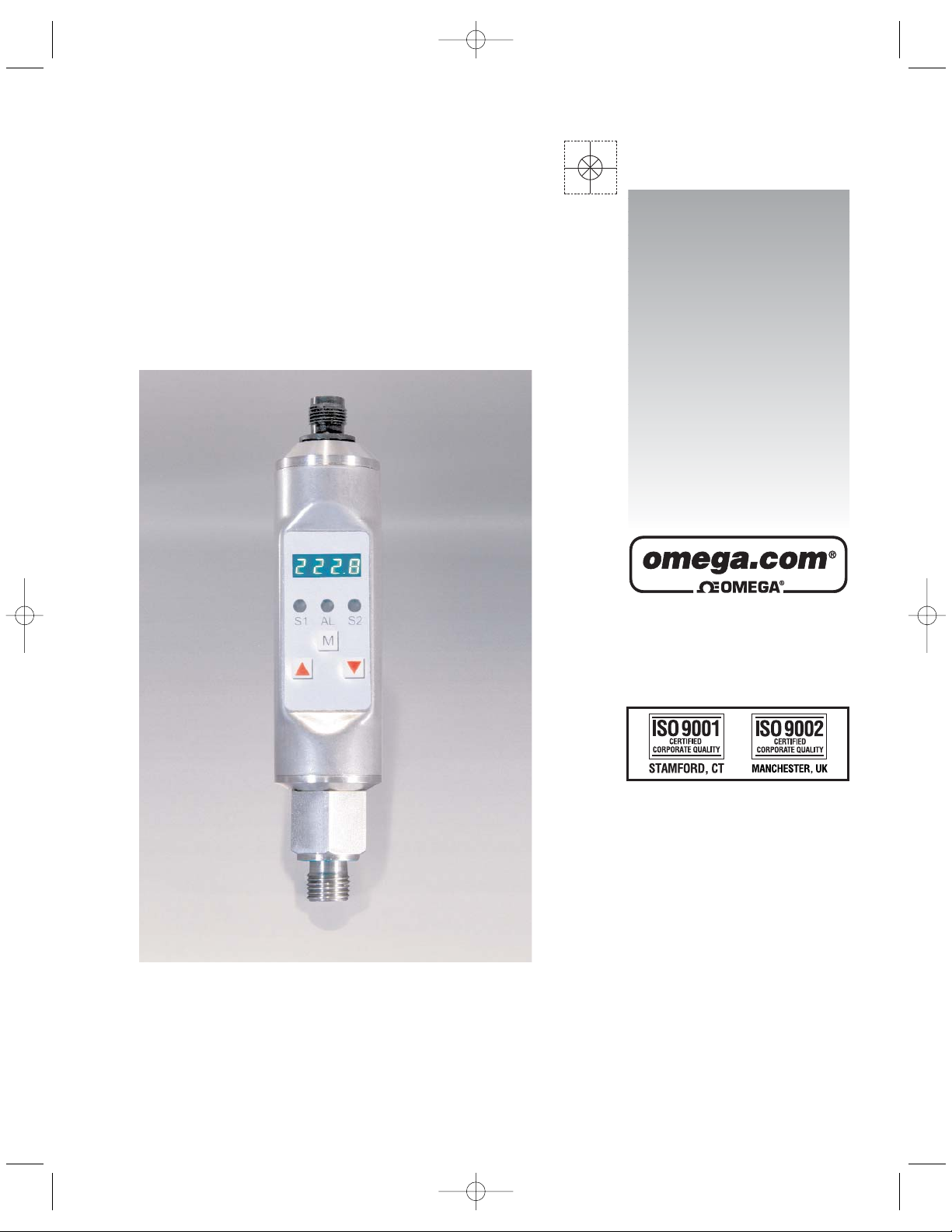
PSW1000
Operating Instructions Dual Pressure Switch
Shop online at
User
’
s Guide
PSW1000.qxp 6/5/2008 3:45 PM Page cov-3
Page 2

2
Servicing North America:
U.S.A.: One Omega Drive, P.O. Box 4047
ISO 9001 Certified Stamford, CT 06907-0047
TEL: (203) 359-1660
FAX: (203) 359-7700
e-mail: info@omega.com
Canada: 976 Bergar
Laval (Quebec) H7L 5A1, Canada
TEL: (514) 856-6928
FAX: (514) 856-6886
e-mail: info@omega.ca
For immediate technical or application assistance:
U.S.A. and Canada: Sales Service: 1-800-826-6342/1-800-TC-OMEGA
®
Customer Service: 1-800-622-2378/1-800-622-BEST
®
Engineering Service: 1-800-872-9436/1-800-USA-WHEN
®
Mexico: En Espan˜ ol: (001) 203-359-7803
e-mail: espanol@omega.com
FAX: (001) 203-359-7807
info@omega.com.mx
Servicing Europe:
Czech Republic: Frystatska 184, 733 01 Karviná, Czech Republic
TEL: +420 (0)59 6311899
FAX: +420 (0)59 6311114
Toll Free: 0800-1-66342
e-mail: info@omegashop.cz
Germany/Austria: Daimlerstrasse 26, D-75392 Deckenpfronn, Germany
TEL: +49 (0)7056 9398-0
FAX: +49 (0)7056 9398-29
Toll Free in Germany: 0800 639 7678
e-mail: info@omega.de
United Kingdom: One Omega Drive, River Bend Technology Centre
ISO 9002 Certified Northbank, Irlam, Manchester
M44 5BD United Kingdom
TEL: +44 (0)161 777 6611
FAX: +44 (0)161 777 6622
Toll Free in United Kingdom: 0800-488-488
e-mail: sales@omega.co.uk
OMEGAnet®Online Service Internet e-mail
omega.com info@omega.com
It is the policy of OMEGA Engineering, Inc. to comply with all worldwide safety and EMC/EMI
regulations that apply. OMEGA is constantly pursuing certification of its products to the European New
Approach Directives. OMEGA will add the CE mark to every appropriate device upon certification.
The information contained in this document is believed to be correct, but OMEGA accepts no liability for any
errors it contains, and reserves the right to alter specifications without notice.
WARNING: These products are not designed for use in, and should not be used for, human applications.
PSW1000.qxp 6/5/2008 3:45 PM Page cov-4
Page 3
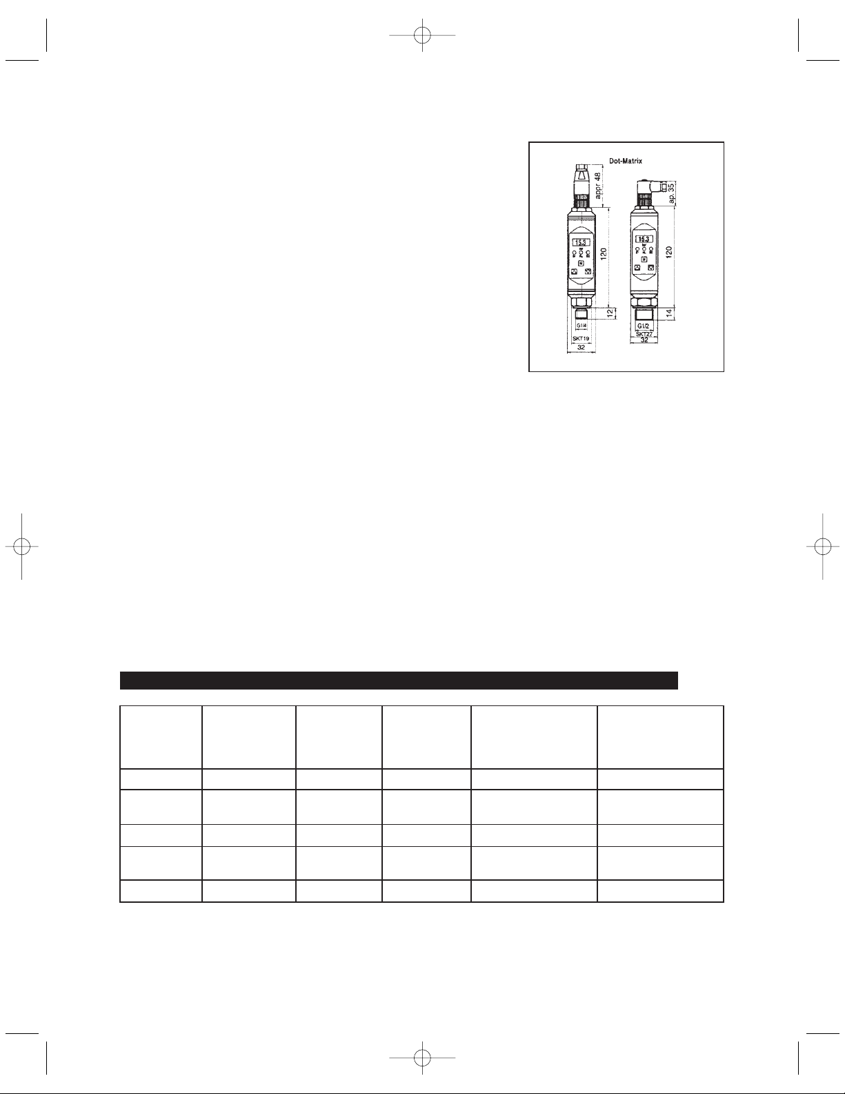
Dimensions (in mm)
3
1. Product Description
2. Starting operations
Electrical connections plug 1 (standard) and power supply
Intended Applications
- The dual pressure switch is a device to monitor system pressure
and has up to two switching outputs and one analog output.
- The instruments must only be installed in systems where the
maximum pressure Pmax or the maximum temperature Tmax is
not exceeded (according to the values on the type label).
- Attention: This device is not designed to be used as the only
safety relevant element in pressurized systems according PED
97/23/EC.
Only assemble or disassemble the device when depressurized!
Connecting the switch
- Mount the pressure switch from bottom to the fitting with a wrench hex 19 (1/4“) resp. hex 22
with 45 Nm torque.
- Electrical connection depends on the type of pressure switch (see type label) according to the
chart below (connection chart plug 2 for interface see page 4).
- When display is adjusted (rotable version only) the unit has to be fixed at the front side with
an allen screw and and allen key 1,5 mm (torque = 3 Nm).
Plug
M 12 x 1
4-pin / 5-pin
PG9 with cable
LifYY11Y
4 / 5x0,25mm
2
Model with 1
switching
output
Model with 2
switching
outputs
Model with 1
switching output
and 1 analog output
Model with 2
switching outputs
and 1 analog output
Pin 1 Brown 18...32 V DC 18...32 V DC 18...32 V DC 18...32 V DC
Pin 2 White - SP2 0,5 A
max.
analog 4...20 mA/
0...10 V DC
analog 4...20 mA/
0...10 V DC
Pin 3 Blue 0 V 0 V 0 V 0 V
Pin 4 Black SP1 0,5 A
max.
SP1 0,5 A
max.
SP1 0,5 A max. SP1 0,5 A max.
Pin 5 Grey - - - SP2 0,5 A max.
PSW1000
PSW1000.qxp 6/5/2008 3:45 PM Page cov-5
Page 4

List of functions: (xxxx = 125% f. s.)
Dialog item Value Description
MENU -1...9999 Primary display, e.g. the value selected in the DISP menu appears
DISP ..... Display value which should be permanently in the display:
act actually measured value
sp1 switching point SP1
sp2 switching point SP2
max maximum peak value
min minimum peak value
ACT. -1...9999 Display of actually measured value in bar
UNIT
bar
psi
psi
HPa
mbar
Fixing the unit
bar = bar The unit is shown in the display appr.
psi x = psi x 10 every 30 sec. for appr. 5 sec.
psi = psi
HPa = Hekto-Pascal
mbar = millibar
SP.1 ..... none switching output deactivated
wind window technology
stnd standard evaluation SP2
erro error output
ON-1 -1 ... xxxx Switch-on point for SP1; if the ON value is smaller than the OFF
value the switching point evaluation is falling
OFF-1 -1 ... xxxx Switch-off point for SP1
DLY1 0,0s...9,9s Switch-on / switch-off delay for SP1 in seconds
INV-1 ..... Inversion of switching output SP1
hlfs high-level-fail-save (normally open function)
Ilfs low-level-fail-save (normally closed function)
SP.2 ..... none switching output deactivated
wind window technology
stnd standard evaluation SP2
erro error output
ON-2 -1 ... xxxx Switch-on point for SP2;
if the ON value is smaller than the OFF value
the switching point evaluation is falling
OFF-2 -1 ... xxxx Switch-off point for SP2
DLY2 0,0s...9,9s Switch-on / switch-off delay for SP2 in seconds
INV-2 ----- Inversion of switching output SP2
hlfs high-level-fail-save (normally open function)
Ilfs low-level-fail-save (normally closed function)
MAX -1 ... xxxx Display of peak value „Max“ (xxxx: = max. 125 % f. s.)
CLRH ----- Delete the maximum value memory
----- no deletion
clr delete value
4
PSW1000.qxp 6/5/2008 3:45 PM Page cov-6
Page 5

CDLY 0,0s...9,9s Time setting to delete the maximum value memory after
switching point SP1 is reached (manual deletion is still possible)
MIN -1 ... xxxx
Display of peak value “Min”
CLRL ----- Delete the minimum value memory
----- no deletion
clr delete value
OFFS -9,9 ...+xx Measured value offset in bar
CUT 0,0 ... +xx Cut-off. e.g. signal suppression at measuring range start in bar
DLDS 0,0 ... 9,9s Time delay for currently displayed value in seconds
ERRC ----- Error messages:
0: -ok- no error
1: max exceeding pos. measuring range
2: min exceeding neg. measuring range
3: dig1 switching output 1 error
4: dig2 switching output 2 error
5: anao analog output error
6: sens sensor error
7: data data error (EEProm)
8: prog program error
9: cal calibration error
V7.X Lev0...Lev2 Programming lock:
Version display with actual input level:
0 : only display of operating parameters, no changes possible
1 : only switching points can be set (“max“ and “min“
memories)
2 : release user level (all operating parameters for customer)
LITH 20 ... 100 Change display brightness 20...100%
(only for units with Dot-Matrix display)
AOZS
(only V7.X)
0 ... 9999 Scale the analog output - start value (e. g. 0 bar = 4 mA)
AOFS 0 ... 9999 Scale the analog output - end value (e. g. 400 bar = 20 mA)
(output signal start value always corresponds to the display initial value, e. g. 0 bar = 4mA)
Maximum turn-down 4 : 1, i.e. at values below 25 % of the measuring range the analog output is switched off
STNO ----- Enter the station number at Profibus DP
RECL ----- SHRT short profile 8 byte
LONG long profile 32 byte
CODE 000...999 Enter the code level: Changes:
Lev1: 471 (up + down five seconds) Lev1-Lev0
Lev2: 740 (up + down + M five seconds) Lev2-Lev0
Lev0: 999
OPT
(onlyV7.X)
----- Display of the unit options
selection of the Profibus-protocol
5
PSW1000.qxp 6/5/2008 3:45 PM Page cov-7
Page 6

Operation:
The pressure switch should be installed and operated only by authorized persons.
After being switched on the PSW1000 runs through a self-test. The device is menu operated and
configured with three keys on the front.
With the “M“ key (= mode) you change between the dialog values and the adjusted / actual values. With
the keys ““= up and ““= down you change between the dialog values in the menu or change the
values / functions in the menues (see below: “List of functions“).
If the dialog is not continued within two minutes the device automatically returns to the measuring
mode. When the programming lock is entered, “LOCK“ appears in the display when an attempt is made
to change values.
Programming:
The setting menu is activated with the mode key. The dialog items are selected with the ““and ““
keys. If the mode key is pressed again the corresponding value for the dialog item is shown and can be
altered with the ““and ““keys. If the dialog with the unit is not continued within two minutes the
device auto-matically returns to the measuring mode without accepting the new values.
To terminate programming more quickly, you can switch back to the measuring mode (primary menu)
from any item in the menu by holding the M-key pressed for five seconds.
If the programming lock has been activated, the values can be shown, but no changes made, i.e. when
Level 0 is active (“LOCK“ appears in the display when an attempt is made to change values).
6
PSW1000.qxp 6/5/2008 3:45 PM Page cov-8
Page 7

WARRANTY/DISCLAIMER
OMEGA ENGINEERING, INC. warrants this unit to be free of defects in materials and workmanship for a
period of 13 months from date of purchase. OMEGA’s WARRANTY adds an additional one (1) month
grace period to the normal one (1) year product warranty to cover handling and shipping time. This
ensures that OMEGA’s customers receive maximum coverage on each product.
If the unit malfunctions, it must be returned to the factory for evaluation. OMEGA’s Customer Service
Department will issue an Authorized Return (AR) number immediately upon phone or written request.
Upon examination by OMEGA, if the unit is found to be defective, it will be repaired or replaced at no
charge. OMEGA’s WARRANTY does not apply to defects resulting from any action of the purchaser,
including but not limited to mishandling, improper interfacing, operation outside of design limits,
improper repair, or unauthorized modification. This WARRANTY is VOID if the unit shows evidence of
having been tampered with or shows evidence of having been damaged as a result of excessive corrosion;
or current, heat, moisture or vibration; improper specification; misapplication; misuse or other operating
conditions outside of OMEGA’s control. Components in which wear is not warranted, include but are not
limited to contact points, fuses, and triacs.
OMEGA is pleased to offer suggestions on the use of its various products. However,
OMEGA neither assumes responsibility for any omissions or errors nor assumes liability for any
damages that result from the use of its products in accordance with information provided by
OMEGA, either verbal or written. OMEGA warrants only that the parts manufactured by the
company will be as specified and free of defects. OMEGA MAKES NO OTHER WARRANTIES OR
REPRESENTATIONS OF ANY KIND WHATSOEVER, EXPRESSED OR IMPLIED, EXCEPT THAT OF
TITLE, AND ALL IMPLIED WARRANTIES INCLUDING ANY WARRANTY OF MERCHANTABILITY
AND FITNESS FOR A PARTICULAR PURPOSE ARE HEREBY DISCLAIMED. LIMITATION OF
LIABILITY: The remedies of purchaser set forth herein are exclusive, and the total liability of
OMEGA with respect to this order, whether based on contract, warranty, negligence,
indemnification, strict liability or otherwise, shall not exceed the purchase price of the
component upon which liability is based. In no event shall OMEGA be liable for
consequential, incidental or special damages.
CONDITIONS: Equipment sold by OMEGA is not intended to be used, nor shall it be used: (1) as a “Basic
Component” under 10 CFR 21 (NRC), used in or with any nuclear installation or activity; or (2) in medical
applications or used on humans. Should any Product(s) be used in or with any nuclear installation or
activity, medical application, used on humans, or misused in any way, OMEGA assumes no responsibility
as set forth in our basic WARRANTY/DISCLAIMER language, and, additionally, purchaser will indemnify
OMEGA and hold OMEGA harmless from any liability or damage whatsoever arising out of the use of the
Product(s) in such a manner.
RETURN REQUESTS/INQUIRIES
Direct all warranty and repair requests/inquiries to the OMEGA Customer Service Department. BEFORE
RETURNING ANY PRODUCT(S) TO OMEGA, PURCHASER MUST OBTAIN AN AUTHORIZED RETURN
(AR) NUMBER FROM OMEGA’S CUSTOMER SERVICE DEPARTMENT (IN ORDER TO AVOID
PROCESSING DELAYS). The assigned AR number should then be marked on the outside of the return
package and on any correspondence.
The purchaser is responsible for shipping charges, freight, insurance and proper packaging to prevent
breakage in transit.
FOR W
ARRANTY RETURNS, please have the
following information available BEFORE
contacting OMEGA:
1. Purchase Order number under which the product
was PURCHASED,
2. Model and serial number of the product under
warranty, and
3. Repair instructions and/or specific problems
relative to the product.
FOR NON-WARRANTY REPAIRS,
consult OMEGA
for current repair charges. Have the following
information available BEFORE contacting OMEGA:
1. Purchase Order number to cover the COST
of the repair,
2. Model and serial number of the product, and
3. Repair instructions and/or specific problems
relative to the product.
OMEGA’s policy is to make running changes, not model changes, whenever an improvement is possible. This affords
our customers the latest in technology and engineering.
OMEGA is a registered trademark of OMEGA ENGINEERING, INC.
© Copyright 2007 OMEGA ENGINEERING, INC. All rights reserved. This document may not be copied, photocopied,
reproduced, translated, or reduced to any electronic medium or machine-readable form, in whole or in part, without the
prior written consent of OMEGA ENGINEERING, INC.
PSW1000.qxp 6/5/2008 3:45 PM Page cov-9
Page 8

M-4677/0508
Where Do I Find Everything I Need for
Process Measurement and Control?
OMEGA…Of Course!
Shop online at omega.com
TEMPERATURE
䡺⻬
Thermocouple, RTD & Thermistor Probes, Connectors, Panels & Assemblies
䡺⻬
Wire: Thermocouple, RTD & Thermistor
䡺⻬
Calibrators & Ice Point References
䡺⻬
Recorders, Controllers & Process Monitors
䡺⻬
Infrared Pyrometers
PRESSURE, STRAIN AND FORCE
䡺⻬
Transducers & Strain Gages
䡺⻬
Load Cells & Pressure Gages
䡺⻬
Displacement Transducers
䡺⻬
Instrumentation & Accessories
FLOW/LEVEL
䡺⻬
Rotameters, Gas Mass Flowmeters & Flow Computers
䡺⻬
Air Velocity Indicators
䡺⻬
Turbine/Paddlewheel Systems
䡺⻬
Totalizers & Batch Controllers
pH/CONDUCTIVITY
䡺⻬
pH Electrodes, Testers & Accessories
䡺⻬
Benchtop/Laboratory Meters
䡺⻬
Controllers, Calibrators, Simulators & Pumps
䡺⻬
Industrial pH & Conductivity Equipment
DATA ACQUISITION
䡺⻬
Data Acquisition & Engineering Software
䡺⻬
Communications-Based Acquisition Systems
䡺⻬
Plug-in Cards for Apple, IBM & Compatibles
䡺⻬
Datalogging Systems
䡺⻬
Recorders, Printers & Plotters
HEATERS
䡺⻬
Heating Cable
䡺⻬
Cartridge & Strip Heaters
䡺⻬
Immersion & Band Heaters
䡺⻬
Flexible Heaters
䡺⻬
Laboratory Heaters
ENVIRONMENTAL
MONITORING AND CONTROL
䡺⻬
Metering & Control Instrumentation
䡺⻬
Refractometers
䡺⻬
Pumps & Tubing
䡺⻬
Air, Soil & Water Monitors
䡺⻬
Industrial Water & Wastewater Treatment
䡺⻬
pH, Conductivity & Dissolved Oxygen Instruments
PSW1000.qxp 6/5/2008 3:45 PM Page cov-2
 Loading...