

Page 1

User’s Guide
Shop online at
omega.com
e-mail: [email protected]
For latest product manuals:
omegamanual.info
PHB23
Benchtop pH/mV/
Concentration Meter
Page 2

OMEGAnet®Online Service Internet e-mail
omega.com [email protected]
Servicing North America:
U.S.A.: Omega Engineering, Inc., One Omega Drive, P.O. Box 4047
ISO 9001 Certified Stamford, CT 06907-0047 USA
Canada: 976 Bergar
Laval (Quebec), H7L 5A1 Canada
Toll-Free: 1-800-826-6342 TEL: (514) 856-6928
FAX: (514) 856-6886 e-mail: [email protected]
For immediate technical or application assistance:
U.S.A. and Canada: Sales Service: 1-800-826-6342/1-800-TC-OMEGA
Customer Service: 1-800-622-2378/1-800-622-BEST
Engineering Service: 1-800-872-9436/1-800-USA-WHEN
Mexico/ En Español: 001 (203) 359-7803 FAX: 001 (203) 359-7807
Latin America: [email protected] e-mail: [email protected]
®
®
®
Servicing Europe:
Benelux: Managed by the United Kingdom Office
Czech Republic: Frystatska 184
733 01 Karviná, Czech Republic
Toll-Free: 0800-1-66342 TEL: +420-59-6311899
FAX: +420-59-6311114 e-mail: [email protected]
France: Managed by the United Kingdom Office
Toll-Free: 0800 466 342 TEL: +33 (0) 161 37 29 00
FAX: +33 (0) 130 57 54 27 e-mail: [email protected]
Germany/Austria: Daimlerstrasse 26
D-75392 Deckenpfronn, Germany
Toll-Free: 0800 6397678 TEL: +49 (0) 7056 9398-0
FAX: +49 (0) 7056 9398-29 e-mail: [email protected]
United Kingdom: OMEGA Engineering Ltd.
ISO 9001 Certified
It is the policy of OMEGA Engineering, Inc. to comply with all worldwide safety and EMC/EMI
regulations that apply. OMEGA is constantly pursuing certification of its products to the European New
Approach Directives. OMEGA will add the CE mark to every appropriate device upon certification.
The information contained in this document is believed to be correct, but OMEGA accepts no liability for any
errors it contains, and reserves the right to alter specifications without notice.
WARNING: These products are not designed for use in, and should not be used for, human applications.
One Omega Drive, River Bend Technology Centre, Northbank
Irlam, Manchester M44 5BD United Kingdom
Toll-Free: 0800-488-488 TEL: +44 (0) 161 777-6611
FAX: +44 (0) 161 777-6622 e-mail: [email protected]
Page 3

Instruction Manual
Benchtop Meter
PHB23
Index
2. Characteristics .......................................................3
3. ........................................................4
Specifications
4. pH Measurement......................................................6
4. pH Electrode Type.....................................................8
5. mV Measurement .....................................................10
6. Product Description ...................................................11
7. Equipment Installation .................................................12
8. Equipment Operation ..................................................13
8.1 Equipment Operation pH - Set Up....................................16
8.2 Equipment Operation pH - Calibration . . . . . . . . . . . . . . . . . . . . . . . . . . . . . . . . . 20
8.3 Equipment Operation pH - Check.....................................21
8.4 Equipment Operation pH - Read .....................................22
8.5 Equipment Operation mV - Set Up....................................23
8.6 Equipment Operation mV - Calibration. . . . . . . . . . . . . . . . . . . . . . . . . . . . . . . . . 26
8.7 Equipment Operation mV - Check....................................27
8.8 Equipment Operation mV - Read.....................................28
8.9 Equipment Operation Temperature - Set Up . . . . . . . . . . . . . . . . . . . . . . . . . . . . 29
8.10 Equipment Operation Temperature - Read. . . . . . . . . . . . . . . . . . . . . . . . . . . . . 32
8.11 Equipment Operation Concentration - Set Up . . . . . . . . . . . . . . . . . . . . . . . . . . 33
8.12 Equipment Operation Concentration - Calibration . . . . . . . . . . . . . . . . . . . . . . . 36
8.13 Equipment Operation Concentration - Check. . . . . . . . . . . . . . . . . . . . . . . . . . . 37
8.14 Equipment Operation Concentration - Read . . . . . . . . . . . . . . . . . . . . . . . . . . . 38
9. Service and Maintenance................................................39
Page 4

2.
Characteristics
· pH / ORP / Temperature / Concentration(ISE)
· Simple 3-key operation.
· Automatic Resolution Selection.
· Automatic Electrode Check.
· Continuous, Average or Hold Readings.
2.
· Non-volatile memory.
· Automatic Calibration for all Parameters.
· Automatic Temperature Compensation recognition.
· Sound Alarm for Minimum and Maximum.
· Recognizes up to 5 Buffer Solutions.
· RS-232 output for computer or printer connection.
· Internal Power Supply 85-240VAc 50/60Hz.
· Records last Calibration, Check and Electrode Change Date.
· Allows user to inform number of Readings before prompting
for Calibration need.
· Allows Clock adjustment and display.
· Allows user to choose between English, Spanish or
Portuguese language.
· User can program User Name.
MEETS GLP STANDARD
Electrode Holder w/ Articulated Arm
Combined pH Electrode
Solutions (250ml. Bottles)
Instruction Manual
Thermo Compensator (ATC)
OPTIONAL
Printer
PHA-EH
PHE-1411
7.00 / 4.01 pH
-
PHE-22R
PRN-1
3
Page 5

3.
Application Measures pH, mV (ORP), Temperature and Concentration
pH
Range -2 to 20 pH
Resolution 0.1 / 0.01 / 0.001 pH
Relative Precision 0.05% (full scale)
Calibration 2 / 3 / 4 / 5
mV
Range ± 1999 mV
Resolution 1 / 0.1 mV
Relative Precision 0.05% (full scale)
Temperature
Range -20 to 120 ºC
Resolution 0.1 ºC
Relative Precision 0.08% (full scale)
Concentration
Range 0.01 to 99.99
Resolution 1 / 0.1 / 0.01 / 0.001
Output RS-232
General
Temp. Comp. Auto / Manual
-20 to 120 ºC
Display
Alphanumeric 2 lines x 16 characters
Dimensions LHD
147 x 145 x 210
Weight
1.2 Kg
Power
110 - 240 V ~ (50/60 Hz)
Tension Fluctuation
± 10% of nominal tension
Overtension
Based on Category II at standard IEC 60864-4-443
Electrical Protection
Class I
Power Consumption (max.)
2.5 VA
Environmental Conditions
Use
Indoors
Altitude
up to 2000 m
Operating Temperature
Between 5 and 40 ºC
Relative Humidity (max.)
80%
Specifications
4
Page 6

3.
For ISE the following curves are already build in at the Set-Up: Fluoride, Iodine, Nitrate,
Potassium, Silver, Sodium, Sulfide, H+, Ammonia, Ammonium, Bromide, Cadmium,
Calcium, Lead, Cyanide, Chloride, Copper and other ions that the user can program.
Available Units: ppm, mg/L, % or mEq/L.
Ranges: PPM 0.02 thru 9000ppm
Resolution: 1, 0.1 or 0.01
Specifications (cont.)
four
5 thru 8pH
0 thru 80C
% 0 thru 9000%
5 thru 8pH
0 thru 80C
mg/L 0.01 thru 12700mg/L
5 thru 8pH
0 thru 80C
mEq/L 0.01 thru 12700mEq/L
Calibration Points: 2, 3, 4 or 5 - fully programable
5
Page 7

4.
pH Measurement
Stable chemical compounds, are electrically neutral when mixed with water.
In order to form a water solution, dismember in positive or negative charged particles.
These charged particles are called "i ”. When we apply differential potential in two electrodes immersed in a
solution, it is possible to verify that positive ions (H , Na and more) will migrate to the negative terminal, that is
why we call them cations. The reverse happens with negative ions (OH , Cl and more) that will migrate to the
positive terminal and we call them anions. The ions freedom to migrate thru a solution is measured with
the solution ". Chemical compounds that produce conductive solutions are called
" ". Those that totally dissociate (strong acids, strong bases and salt) are called "
lectrolytes Strong
E
Electrolytes
“Electrical Conductivity
".
The others whose dissociation is not big (acids and weak bases) are called " ". For an
hypotetical chemical compound "MA" that dissociates in cations and anions , the reaction can be written as:
ons
++
--
+-
M A
Weak Electrolytes
“ “
MA M A
The arrow indicates that exists a balance between MA not dissociated and the ions M and A dissociated.
++ -
+and -
The extension that this reaction moves to the right or left, varies from one compound to the other and with the solution
Temperature.
For a specific temperature, there is a relation between the ions activity and the non dissociated molecules, that can vary
between 0 up to 100%. This relation is called K Dissociation and it is expressed by the equation:
K = aM * aA- / aMA (EQ-1)
Where: K =
ions activity M+.
For Chloridric acid, the is practically infinity, caused by the complete dissociation for ions and So it is a strong acid:
CTE dissociation.
aM+ =
aA- =
ions activity A-.
aMA =
dissociated molecules activity MA.
"K" .
+
HCl H Cl
+ + -
+-
HCl
On the other hand, Acetic acid has a low . Reacts as the following way:"K"
CH COOH H CH COO
33
+ + -
Few hydrogen ions result at the solution, so the acetic acid is an weak acid when the most present ion is the OH-, the
solution is alkaline.
NaOH Na OH
The sodium hydroxide is totally dissociated, this is the reason for being a On the other hand the Ammonia
Hydroxide do not dissociate too much, this the reason for being a .
WEAK BASE(NH OH)
4
NH OH NH OH
44
+ + -
STRONG BASE.
+ + -
As we can see, for both acids and bases the strength of a solution depends on the H+ or OH- ion numbers available that
depends not only on the compound concentration at the water, but also on the " " Pure water dissociates for
K dissociation.
Ions H+ and OH-, but it is very weak.
HOH H OH
+ + -
The water molecules number dissociated is low, in comparison with the non dissociated, so we can consider as an
activity of HOH equal to 100%.
6
Page 8
4.
pH Measurement (cont.)
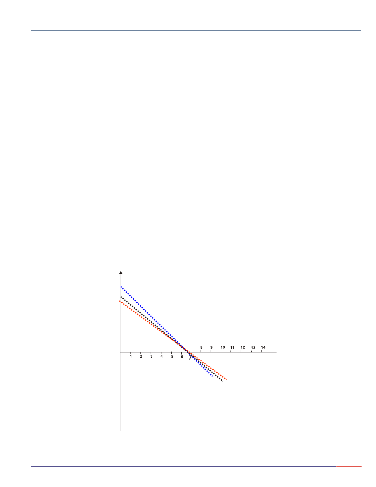
At 25°C the of water has a value of 10 where we can take that is the activity product (aH+) by
"K" dissociation (EQ-1)
(aOH-) is equal to ion OH-, the solution is neutral and activities of H+ and OH- must be both of 10 mols / L.
If a strong acid, such as HCl, is added to water, many ions H+ are added; this should reduce the number of ions OH-. For
example: if added HCl until the OH+ activity turns 10-2 the OH- activity must turn 10-12. The hydrogen potential scale is
Established by a definition merely operational, the acid degree or activity of ions H+ will be expressed by therm "pH”
(Hydrogenionic potential).
The pH will be defined as:
pH=-log |aH+|
If the activities of ion H+ is 10-x so pH is "x".For example, at pure water @ 25°C, the hydrogen ion activity is 10-7, so the pH
Is 7 @ 25°C.An acid solution has more ions H+ then OH-.So the ions H+ activities will be bigger than 10-7, being, 10-6, 10-5
and more. The pHof an acid solution by definition, must be lower than 7, will be 6, 5, 4...
If the OH- number exceed the number of ions H+ the H+ activity must be lower than 10-7, being, 10-8, 10-9 and more... The
pHwill be bigger then 7, will be 8, 9, 10...
To avoid solution ionic concentration modification being measured it is necessary that the current that goes thru the circuitry
composed by the galvanic cell (pH electrode) be minimum (I < 1pA), such as the voltage drop caused by the internal
resistance of the same electrochemistry cell being null, not to cause measuring errors. Such condition restrict the choice to
Choose the instrument to a "HIGH IMPEDANCE VOLTMETER”. The instrument will have a scale graduated in pH,
calibrated by glass electrode and a reference electrode based on the relation between the pH and the electromagnetic force
Of the cell.
E = E0 - KT (pH)
Above equation, define the equation of a line, whose decline is and whose origin ordenate is . The electrode must
-KT E
have a zero volts point (isopotential), that can be achieve performing a correspondence to 7 to zero volts, to any
temperature, using a internal BUFFER at the glass electrode, whose pH variation with the temperature compensates to the
temperature variation at the electrode.
The approximate decline of the line mV / pH involves the factor adjustment of factor KT @ 59.16 mV decade of pH, @ 25°C
by controlling the equipment “ that does the decline around the isopotential. The temperature compensator is
SENSITIVITY”
applied to correct the decline based on real sample temperature, varying the definition of the instrument, relating to a
1pHunit, from54.20 mV @ 0°C up to 66.10 mV @ 60°C.
600 -
500 -
400 -
300 -
200 -
100 -
-100 -
-200 -
-300 -
-400 -
-500 -
-600 -
0
7
Page 9

4.
pH Measurement (cont.)
Electrode Description
1 - - rugged construction, in order to avoid ease breakage.
pH sensing Bulb
2 - - chemically inert.
Glass Body
3 - .
Punctual Ceramic
4 - - ease operation for electrolyte solution filling.
Seal
5 - - assuring stable readings..
Low Noise Cable
6 - - chemically aggressively resistant.
Polypropylene Cap
7 - - avoid contamination with solutions that contain Silver, Mercury, Sulfite, etc.
Ionic Barrier
Avoid AgCl preciptations. Provides quick readings on temperature variations.
8 - - contains reference electrolyte solution for transportation or storage.
Transportation Cap
9 - (on reillable electrodes only).
Electrolyte Fill Hole
10 -
Argental Reference.
Electrode Usage Instruction
DIAPHRAGM
BULB (1)
TRANSPORT CAP (8)
(3)
1 - Before using the electrode, verify it’s body for possible mechanical defects or cracks
and in case it occur, replace it immediately.
2 - Take off the transportation cap and rinse the electrode with distilled water, remove
eventual crystallization at the diaphragm (3). The transportation cap must always be
used when transporting the electrode, avoiding dehydration of the bulb (1).
3 - Remove the seal (4) in order to establish Atmospheric Pressure (only applicable for
refillable electrodes) an d cl ose it aga in .
4 - Eliminate possible air bubbles that may occur internally at the bulb (1), by shacking
the electrode vertically.
5 - On Refillable electrodes, the electrolyte level must be at a maximum of 10 mm
below the hole (9).
6 - Always refill, when necessary, the electrolyte level with 3 MKCl thru the hole (9). On
Bridge Electrolytic Electrodes, with the proper bridge (see table 1) thru the hole (9).
7 - When the Electrode is not in use, always immerse into electrolyte reference.
8 - To measure, just immerse the electrode into the sample, covering the diaphragm (3).
9 - Switching from one solution to other, always wash electrode with distilled water.
REFILL HOLE
(9)
SEAL
(4)
8
Page 10

4.
Buffer Soutions
These are solutions that resist the ph variations, by effect of adding acids or bases and/or by dilution, all happening like if they
had an acid reserve and/or alkaline. Selected solutions are used as standard for calibration of ph meters based on operational
definition. They are fixed points that define the pH scale. Composed, usually, by a weak acid mixed with its own strong base salt.
The KCl is a neutral salt, so does not interfere at the pH value. It can be used to raise the conductivity at the sample, in case we
Are measuring a weak electrolyte.
Supplied in 475ml Bottles (other volumes upon request).
pH Measurement (cont.)
OMEGA offers the following Buffer Solutions:
PHA-4 4.01pH
PHA-7 7.00pH
PHA-10 10.01pH
9
Page 11

5.
Oxide Redox Potential Measurement
In order to measure potential redox it is used metallic electrodes, generally Platinum or Silver. This type of
electrode refers to chemical reactions in solutions that operate only by electrons transference. Such reactions
occur with composed elements presenting two or more oxidizing stages. Ex.: Fe2+ / Fe3+. The redox
measurement applications in a determined process, complies with previous knowledge of certain factors:
presence of infectants capable of competing with the main redox reaction, approximate values of the ions activity
coefficients entering the final equation of the potential differential, approximate speed of the reaction to be
controlled, necessary or not to control the pH. At Oxide reduction systems where the ions H+ take part at the
reaction, the redox potential depends on the pH. In order to obtain a complete description of such systems it is
necessary to indicate, besides the reference electrode, the pH value. The temperature has two effects over the
redox potential. First it enters as a factor over the logarithem of equation. This means that a determined
reason of the ionic activity, the electrode will develop a different potential. Second, the temperature influence the
Ionic activity on each ion of the solution.
MV Measurement
NERNST
10
Page 12
Product Description
6.
3.
Composição do produto
1
2
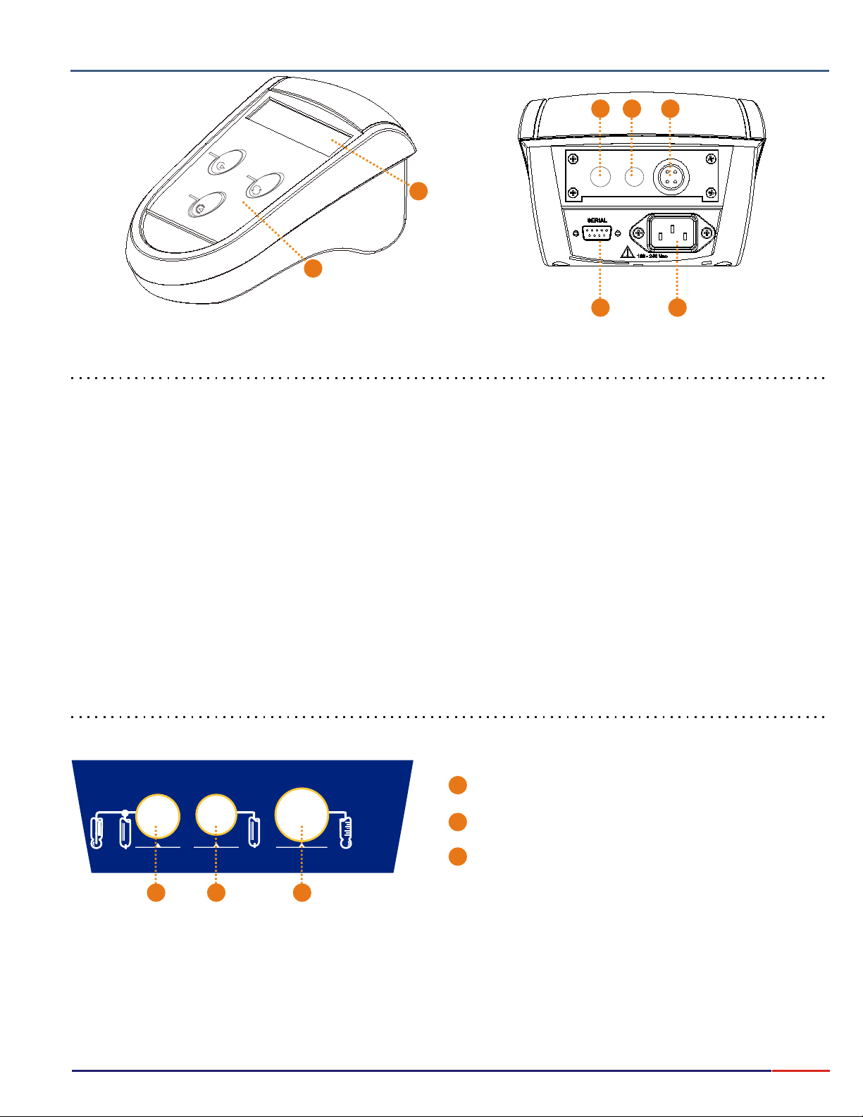
Items Descrption
1 - Alphanumeric Display 2 lines x 16 characters
2 - Keyboard: with 3 tactile membranes
3 - Connector : pH Electrode / reference inlet.
4 - Connector 4mm: Reference electrode inlet.
5 - Connector : Thermocompensator inlet (DMF-P1X).
6 - : for printer or computer connection.
Serial Output
7 -
Connector (AC Power)Male 3 poles
BNC
Banana
BNC
3
4
5
6 7
Symbols
Reference
Electrode
1
Reference Temperature
2
3
1
pH Combined Electrode Symbol
Reference Electrode Symbol
2
Thermocompensator Symbol
3
11
Page 13

Composição do produto
3.
7.
For a better performance of the equipment, user must follow below steps:
1 - Position the equipment in such a way to avoid power cord disconnection;
2 - Install the equipment leaving lateral space for its correct operation and for easy maintenance;
3 - Disconnect the equipment from power before any maintenance.
In case of maintenance, please contact OMEGA by phone 800 872.9436;
4 - A circuit breaker should be installed for the equipment(s) power, compatible with the instrument power;
5 - This breaker should be installed close to the equipment(s) for the operator easy access;
6 - This breaker must be identified as a protection device to the instrument(s) and must be in accordance with
standards IEC 60947-1 and IEC 60947-3 (item 6.11.3.1 from general standard). The breaker cannot interrupt
the ground conductor.
7 - Use a proper outlet, as shown below:
Equipment Installation
Neutral
Ground
Phase
12
Page 14
8.
Equipment Operation
Basic Operations
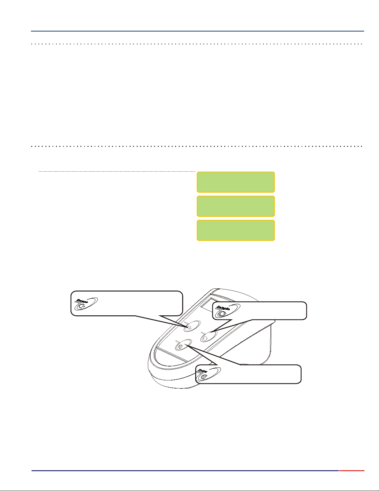
1 - The software offers self explanatory menus for easy interaction with the user. The menu shows the selected option as
Flashing. Use the
<SELECT>
key to modify the flashing option and select a different one, then press to confirm it.
<ENTER>
2 - In case of a mistake, or data modification or to return to a prior menu, press . While at Reading Mode, press
and hold
understand that the user really desires to exit the Reading Mode.
3 - The equipment stores the configuration on a non volatile memory (E PROM). Even when turned off, the last set up
Configuration will be stored.
<ESCAPE>
key for about 5 seconds in order to exit this mode. This is necessary in order for the instrument
<ESCAPE>
2
key
Turning On the equipment
1 -Turn on the equipment by pressing . The display will show the following menus until reached the Main Menu.
Press key to turn if on<ENTER>
<ENTER>
OMEGA
MODEL PHB23
AUTO-CHECK 100%
DISPLAY TEST
Return to prior menu for data
modification and to reach the
Turn off screen.
Select the menu option.
Turns on the instrument and
Also confirms the selected option,
13
Page 15

8.
Equipment Operation (cont.)
To turn ON the equipment, press and hold key. Make sure the power cord is plugged correctly!
The menus are self-explanation with it’s respective options, selected by pressing the key.
After making your selection(flashing option), using key, press the key to confirm
Your selection. This manual will represent the Flashing Option always in .
In case of any error or if you decide to change your selection, press the key to move the
screen one step back so you can make the necessary changes, or hold this key for about 5seconds in
order to turn OFF the equipment, until the message “SWITCH OFF? YES / NO” shows off on screen.
SETUP OPERATION
This equipment is supplied with a non-volatile memory (E2PROM), to store it’s operational set up
(resolution, reading mode, calibration, etc).
Even if disconnected from it’s power supply, it will not loose the information saved for work!
Before you start to work with this equipment, please review the setup, so you can program the equipment
based on your application!
After powering the equipment on, by pressing and holding Key, the equipment will perform an
Auto Check and will then stop at Main Menu(Select Function) with options for the user to Select the desired
Function. pH function will be flashing as a default. Press key to move around until you reach
the desired selection(flashing option) then press key to access the sub-menu were you will find
the SETUP FUNCTION(SET.). Press the key until SET is flashing, then press key
to confirm it. The equipment will prompt for a password, press the following keys in sequence
<SELECT><ENTER><ESCAPE>
Always use key to move around the options and press key to confirm this option.
Refer to page 16 for description of Set Up Screens.
CHECK OPERATION
The Check Sensor option is very useful, it gives the user the conditions to check the sensibility of the
sensor. The operation is self-explanatory! From main menu press the key to choose the
desired function, then press key to confirm. Select option Check, then press key to
confirm option. The display will guide you thru the process.
READING OPERATION
Under this operation, you’ll find CALIBRATION and READING options .If you want to calibrate the sensor,
press the key to select the Calibration option(flashing option - CAL), then press key
to confirm. The program will guide you step by step on how to calibrate the sensor. If you need to use the
READING option, press the key to select READ (flashing option), then press key
and the display will show the following format:
<SELECT> <ENTER>
<ENTER> <ENTER>
<SELECT> <ENTER>
<SELECT> <ENTER>
<ENTER>
<SELECT>
<SELECT> <ENTER>
RED Color
<ESCAPE>
<ENTER>
<SELECT>
<ENTER>
<SELECT> <ENTER>
and follow the instructions on the display.
<SELECT>
1 - The Prompt signal will flick at each reading as per setup. Don’t forget that this setting is made when you
setup the readings in the SETUP menu (Reading Mode).
2 - The Measured Value and Reference Temperature(chosen at setup).
3 - Sample Temperature
4 - Electrode’s Sensibility
5 - Barr Graph will show, if chosen this option during Set Up Operation.
4
99% 25.0°C
1
8.96 pH @ 25°C
3
2
5
================
1
8.96 pH @ 25°C
2
14
Page 16

8.
Equipment Operation (cont.)
IMPORTANT INFORMATION
1 - In case you want to quit Reading operation, press and hold key for about 5 seconds in
order to be recognized by the equipment. This time is necessary to certify the user desires to quit this
mode.
2 - When the equipment is turned on again, the set up will follow initial conditions including the changes
prior to when it was turned off.
To turn off the equipment, press and hold key until the message to Switch Off shows on
screen, then by pressing key, choose YES to turn if off or NO to continue working and press
<ENTER>
BASIC OPERATION
The menus are self-explanatory for easy operation. To input new information or change the pre-seted
information, the menu offers flashing options, selected by key and confirmed by .
The key is used to change options or to correct data (every time the user press
The screen will move back one step or one option).
This manual will represent the Flashing Option always in .
key to confirm the option chosen.
<ESCAPE> <ESCAPE>
<SELECT>
<ESCAPE>
<ESCAPE>
<SELECT> <ENTER>
BLUE Color
The Calendar/Clock will be displayed, when the unit is turned off, if user chooses this option
during Set Up Operation.
The program will automatically records the last Calibration and Check Dates.
The program also offers the user, capability to store the last electrode Change date, but this is NOT
done Automatically, the user needs to access the Set Up operation in order to store this date.
15
Page 17
3.
8.1
Composição do produto
Equipment Operation pH - Set Up
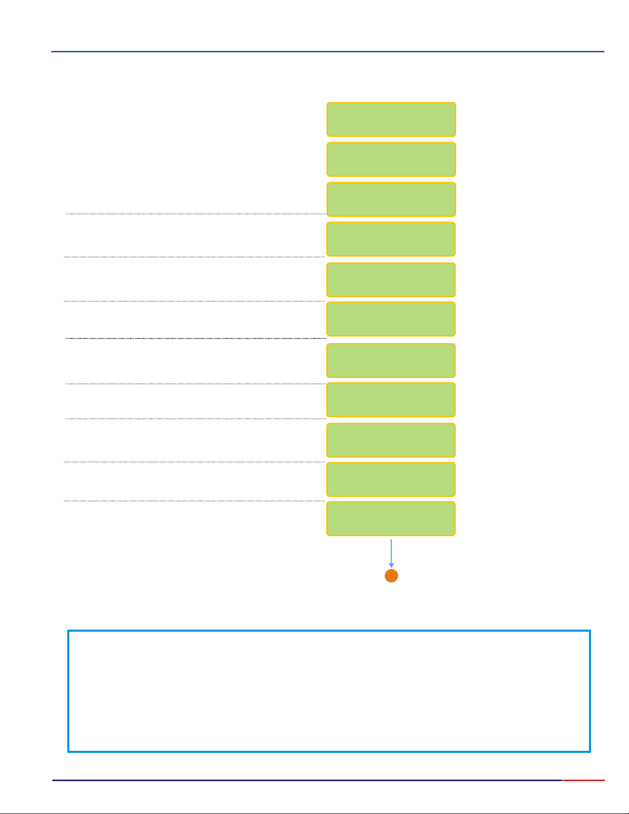
Press key in order to turn on the instrument.<ENTER>
Press key until option flashes, then
<SELECT> pH
press key to confirm the option chosen.
<ENTER>
Press key until option flashes, then
<SELECT> Set Up
press key to confirm the option chosen.
<ENTER>
A password is required to access the Set Up mode.
Press in sequence ,, .<SELECT> <ENTER> <ESCAPE>
User has the option to choose the desired language.
Press key until the desired option flashes,
then press key to confirm the option chosen.
<SELECT>
<ENTER>
This Screen is default and cannot be changed.
OMEGA
MODEL PHB23
AUTO-CHECK 100%
DISPLAY TEST
SELECT FUNCTION
mV ºC CONC.pH
pH : Read /
/ CheckSet Up
PASSWORD
_ _ _
Language:
Portug.
English/Spanish
RANGE
-2 to 20 pH
Select the Resolution by pressing key.
Option chosen will flash. Then press key to
confirm option chosen.
Option to choose how many calibration points you need.
Press key until desired option flashes, then
<SELECT>
press key to confirm chosen option.
<ENTER>
User can fully adjust the Buffer values. In order to get to
know how to change the values, please refer to below
instructions.
<SELECT>
<ENTER>
Resolution
/ /0.0010.1 0.01
Calibration
Points: /3/4/52
Iso = 7.00pH >
Sens.= 4.01pH ><<
B
Go to Page 17
Every time you see the symbols “ ” or “<”, that means that the user can adjust the displayed value up or down.
To increase the value press key until “ ” flashes, then press to confirm, then press key and at every touch the
value will increase by one unit.
To decrease the value press key until “<” flashes, then press to confirm, then press key and at every touch the
value will decrease by one unit.
If a mistake is made, press key to return and correct the value!
If user press and holds key, the units will move faster, but be careful when gets closer to the desired number, as you can miss it
and if that happens, press key to move back and Correct the mistake.
<SEL>
>
<SEL> <SEL>
<SEL> <SEL>
<ESC>
<ESC>
>
<ENT>
<ENT>
16
Page 18
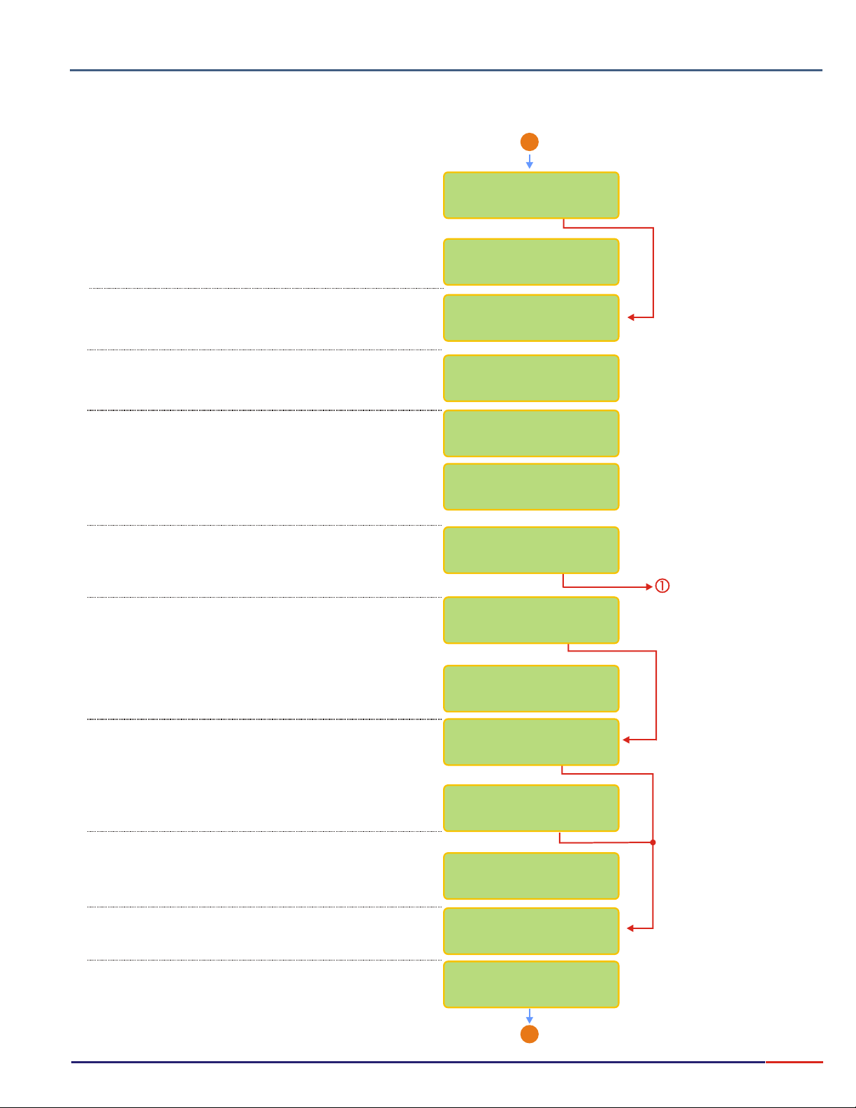
8.1
3.
Equipment Operation pH - Set Up
Composição do produto
From page 16
B
User can instruct the instrument to inform that
calibration is needed.
User can program the number of readings, before
instrument prompts for calibration. Refer to page 16
on how to adjust the number.
User can choose Temperature as Reference or
Absolute.
User can choose adjust the Reference Temp.(***)
For Alcohol applications choose 20°C.
User can choose between the following Reading Modes:
Continuous - Read continuously after time is set
Average - Reads the average after time is set
Hold - user must press key to Read
User can program the time between Readings. Refer to
Page 16 for instructions on how to adjust this time.
User can program the display to show information like
Barr graph, Clock, Calibr., Check and Electr. Change
Dates and more.
<ENTER>
Calibr.Inform.
/ Yes No
Calibrate with:
200 Readings ><
Temperature:
/ Ref. Abs.
Ref. Temperature
25°C <>
Reading Mode
/Aver./HoldCont.
Reading Time:
1s ><
Display Config.?
/ Yes No
Go to Page 18
User can choose if desire to have Barr graph shown
above the Reading screen. When Bar Graph is
displayed, the information about Sensibility and Sample
Temperature will not be displayed!
User can now adjust the Minimum and Maximum
values for the Bar Graph.
User can choose to display date/clock on display,
when equipment is turned off.
User can adjust date and clock, if desired.
Use key to change numbers and when
<SELECT>
finished, press key. If a mistake is made,
press key to move back.
<ESCAPE>
User can set up the instrument to store and display
the last Calibration date or Not.
User can set up the instrument to store and display
the last Check date would or Not.
<ENTER>
Bargraph ?
/ Yes No
Min.: 0pH >
Max.: 14pH ><<
Clock ?
/ Yes No
Adjust Clock?
/ Yes No
15/06/2006
15:00:00
Calibration Date?
/ Yes No
Check Date?
/ Yes No
B
Go to Page 18
17
Page 19
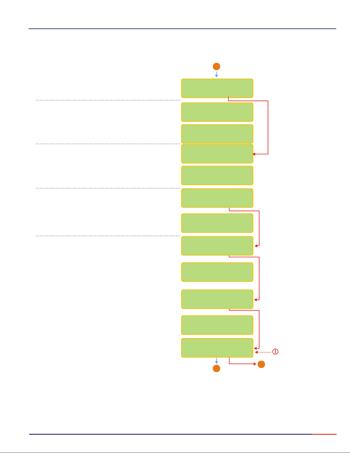
3.
8.1
Composição do produto
Equipment Operation pH - Set Up (cont.)
From Page 17
B
User can change the last Electrode Change date.
This is not done Automatically
User can now insert the electrode change date into the
instrument. Use key to change numbers and
when finished, press key. If a mistake is made,
<ESCAPE>
press key to move back.
User can choose if instrument would Beep when Stability
is reached during Read Mode or Not.
User can choose if instrument would Beep on Keyboard
touch or Not.
User has the option to program the user name of the
operator.
In order to program the operator name press
key to change numbers and when finished, press
<ENTER> <ESCAPE>
key to move back.
During this sequence, user will be able to choose alarms
and also adjust it’s values.
Will be able to choose if RS232 is needed and if
connected to a PC or a Printer.
Press key until desired option flashes, then
<SELECT>
press key to confirm the option chosen.
<ENTER>
<SELECT>
<ENTER>
<SELECT>
key. If a mistake is made, press
Change Electr.?
/ Yes No
Inform New
electr.Chan.date
15/06/2006
15:00:00
Beep on Stab.?
/ Yes No
Keyboard Beep?
/ Yes No
Operator ?
/ Yes No
Operator Name :
_______
Max. Alarm?
/ Yes No
Max. Value:
12pH ><
In order to adjust the values, refer to page 16.
Min. Alarm ?
/ Yes No
Min. Value:
2.0pH ><
RS232 Output?
/ Yes No
B
Go to Page 19
From Page 17
End
X
18
Page 20
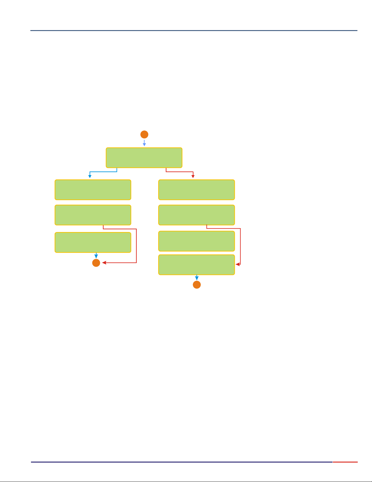
Composição do produto
3.
8.1
Equipment Operation pH - Set Up (cont.)
User can program the PC or the Printer to be used at the RS 232 output, Speed Transmition and Printing modes, intervals
and Statistics.
From Page 18
A
RS232 Output:
/ PC Printer
Speed (100bps)
24 48 9612
Transm. Mode
./Cont Man./Stab
Intervalo de
Impressao 2s ><
X
End
Speed (100bps)
24 48 9612
Printing Mode
./Cont Man./Stab
Printing
Interval 2s ><
Statistic?
/ Yes No
X
End
CONT.: Print continuously (based on the
printing interval chosen)
Prints the Read value just after
MAN.:
pressing key. But only after the
read value is stabilized (an arrow is displayed).
STAB.: Prints only one time, after the
reading is stabilized (an arrow is displayed).
<ENTER>
19
Page 21
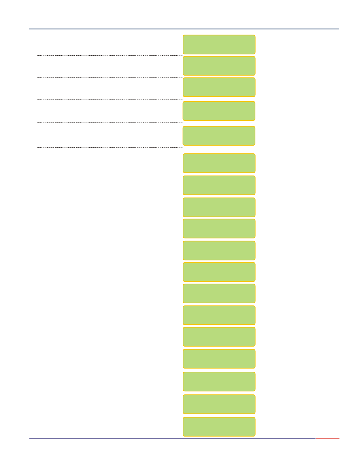
Composição do produto
3.
8.2
Press key until option flashes, then
press key to confirm the option chosen.
Press key until option flashes, then
press key to confirm the option chosen.
Equipment Operation pH - Calibration
<SELECT> pH
<ENTER>
<SELECT> Read
<ENTER>
Select Function
mV ºC CONC.
pH
pH: /
Read
Set Up / Check
:
Press key until option flashes,
<SELECT> Calibrate
then press key to confirm the option
The last Electrode Change date and time will be
displayed. This date/time is changed manually during
Set Up operation.
The last Calibration date/time will be displayed!
Dip electrode into 7.00pH Buffer. This buffer value was
chosen at Set Up Operation.
If no Temperature Probe is attached to the instrument,
User will be prompted to adjust the Compensation
Temperature.
Then press key to confirm the option
chosen.
Wait.
Remove the electrode from 7.00pH Buffer and wash it
using deionized water.
Dip electrode into 4.01pH Buffer. This buffer value was
chosen at Set Up Operation.
<ENTER>
<ENTER>
pH: R / ead
Calibrate
PH Elect.Change:
00/00/00 08:00
Last Calib.Date:
00/00/00 08:00
Place Electrode
@ Buffer: 7.00pH
Man. Comp. Temp.
25ºC ><
READY ?
WAIT
Wash Electrode
Ready ?
Place Electrode@
Buffer: 4.01pH
Then press key to confirm the option
chosen.
Wait.
The Sensibility of the electrode will be displayed
Wash the electrode using deionized water, then press
<ENTER>
Use is prompted to go to sample, if desired, press
<ENTER>
After pressing key user will be able to adjust
the Compensation Temperature. Dip electrode at
sample, then press key to proceed with
Sample Reading.
<ENTER>
key to continue.
key, if not, press key.
<ENTER>
<ENTER>
<ESCAPE>
Ready ?
WAIT
Sens.= 100%
Wash Electrode
Ready ?
Go to Sample!
Ready ?
Man. Temp.Comp.:
23.4ºC ><
100.0 % 25.5ºC
8.00pH @ 23.4ºC
20
Page 22
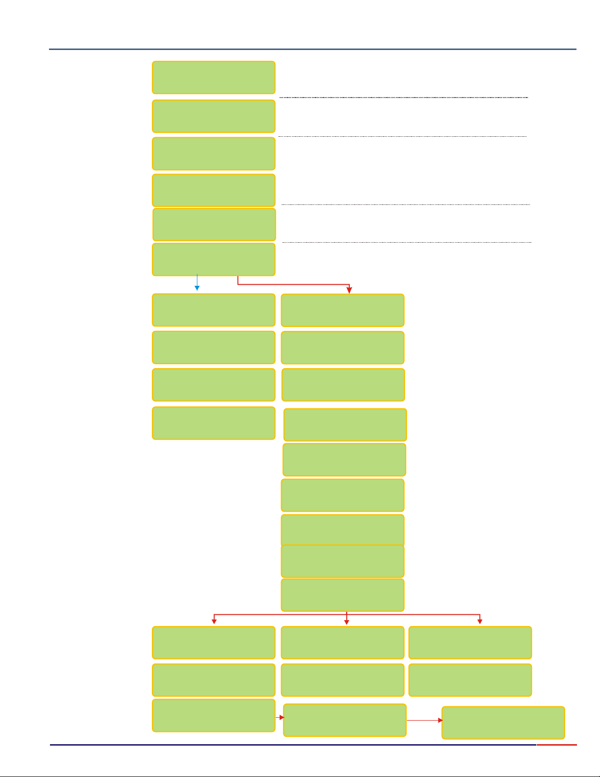
3.
8.3
Composição do produto
Equipment Operation pH - Check
Press key until option flashes, then
Select Function
mV ºC CONC.pH
pH: R /
Set Up /
ead
Check
<SELECT> pH
press key to confirm the option chosen.
<ENTER>
Press key until option flashes, then
<SELECT> Check
press key to confirm the option chosen.
<ENTER>
Electrode
Check
PH Elect.Change:
The last Electrode Change date and time will be displayed.
This date/time is changed manually during Set Up operation.
00/00/00 08:00
Last Check Date:
00/00/00 08:00
Response Time?
/ Yes No
Place Electrode
@Buffer: 4.010pH
READY ?
WAIT
RESPONSE TIME
2s <ENTER>
The last Check date/time will be displayed!
User will be able to check the Response Time of the Electrode.
Place Electrode
@Buffer: 7.00pH
Dip electrode into 7.00 or 4.00pH Buffer.
This buffer value was chosen at
Set Up Operation.
READY ?
WAIT
WASH ELECTRODE
READY ?
Place Electrode
@Buffer: 4.010pH
READY ?
Then press key to confirm
the option chosen.
Wait.
Remove the electrode from 7.00pH
Buffer and wash it using deionized
water.
Dip electrode into 4.01pH Buffer.
This buffer value was chosen at
Set Up Operation. Then press
<ENTER>
chosen.
<ENTER>
key to confirm the option
If Sensibility is <80%
Electr.: Bad
Wash electrode
w/thiourea
and Pepsin
Persisting Bad
WAIT
Check
Result
Sens.: 100.0%
If Sensibility is >=80 and <=95%
Wait.
The Sensibility of the electrode will be
displayed
The program will then display the
analysis, based on the electode
sensibility.
If Sensibility is >=95%
Electr.: Good Electr.: Very
Good
Wash electrode
Ready ?
Consult OMEGA
Cust.Service
Wash electrode
Ready ?
(800)872-9436
<ENTER>
21
Page 23
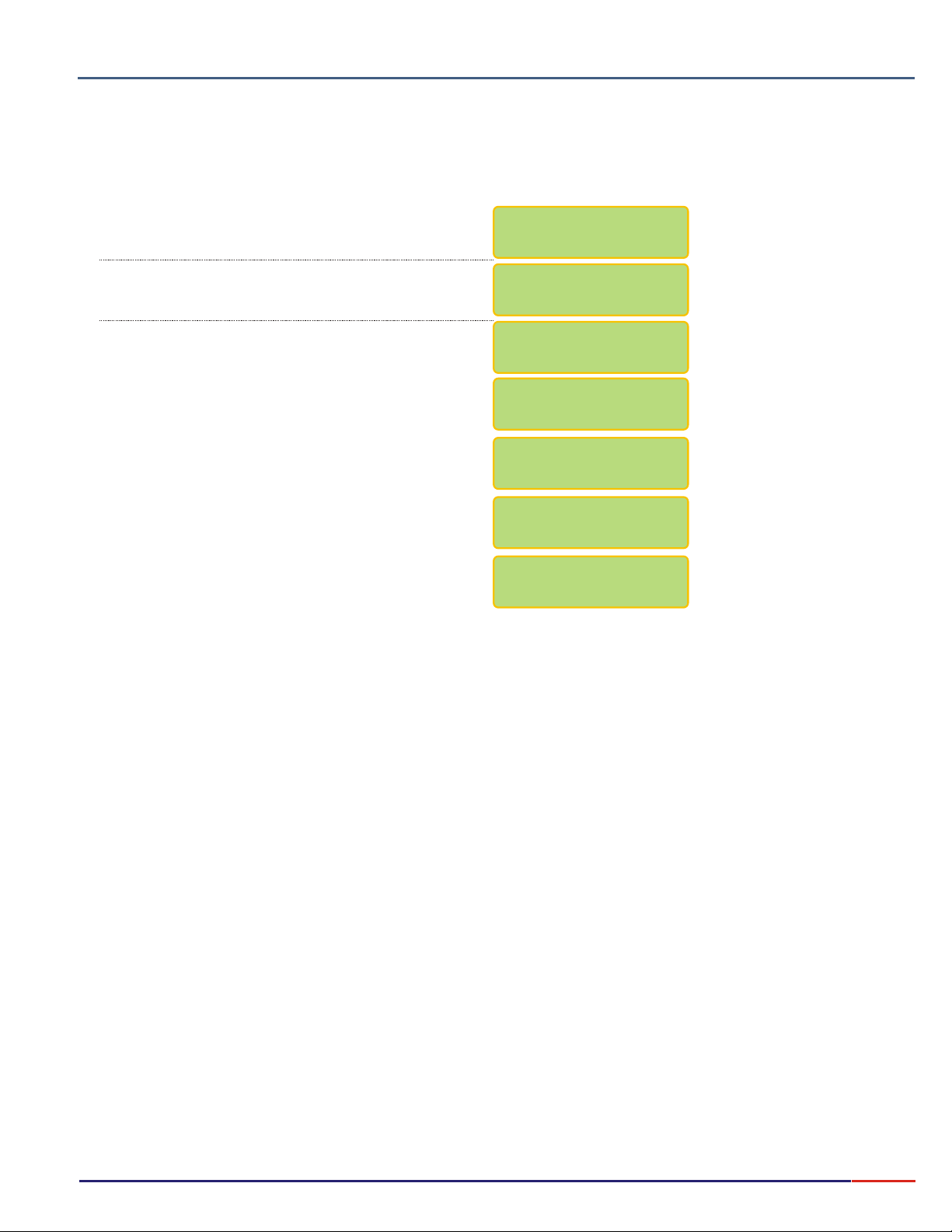
Composição do produto
3.
8.4
Press key until option flashes, then
press key to confirm the option chosen.
Press key until option flashes, then
press key to confirm the option chosen.
Press key until option flashes, then
press key to confirm the option chosen.
Equipment Operation pH - Read
<SELECT> pH
<ENTER>
<SELECT> Read
<ENTER>
<SELECT>
<ENTER>
Read
SELECT FUNCTION
mV ºC CONC.pH
pH: /
Read
Set Up / Check
pH: /
Read
Calibrate
Dip electrode into sample and when Ready, press
<ENTER>
The display will show the electrode sensibility, the
sample temperature (if Temperature Probe is attached),
the pH Value and the Reference Temperature.
Press key and user will be able to adjust the
Compensation Temperature. Refer to page 16 for
instructions on how to adjust this value.
Press and hold key for about 5seconds, if
user desires to exit Reading Mode. If so, the message
End Report will be displayed for the user to inform if this
would be the end of the Application and the final data
would then be sent to the PC or printer, finalizing the
Report.
key to confirm.
<SELECT>
<ESCAPE>
Go to Sample!
Ready?
100.0 % 25.5ºC
3.59pH @ 25ºC
Man. Comp.Temp.:
25.5ºC ><
End Report?
/ NoYes
22
Page 24
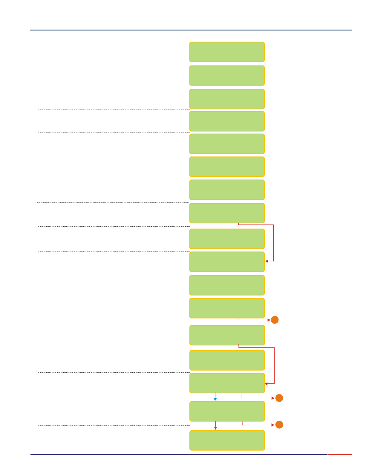
Composição do produto
3.
8.5
Press key until option flashes, then
press key to confirm the option chosen.
Press key until option flashes, then
press key to confirm the option chosen.
Equipment Operation mV - Set Up
<SELECT> mV
<ENTER>
<SELECT> Set Up
<ENTER>
Select Function
pH ºC CONC.mV
pH: Read /
/ CheckSet Up
A password is required to access the Set Up mode.
Press in sequence ,, .<SELECT> <ENTER> <ESCAPE>
User has the option to choose the desired language.
Press key until the desired option flashes,
then press key to confirm the option chosen.
Select the Resolution by pressing key.
Option chosen will flash. Then press key to
confirm option chosen.
Option to choose the calibration standard. Refer to page
16 on how to adjust the value, then press key
to confirm chosen option.
User can instruct the instrument to inform that calibration
is needed.
User can program the number of readings, before
instrument prompts for calibration. Refer to page 16
on how to adjust the number.
User can choose between the following Reading Modes:
Continuous - Read continuously after time is set
Average - Reads the average after time is set
Hold - user must press key to Read
User can program the time between Readings. Refer to
Page 16 for instructions on how to adjust this time.
User can program the display to show information like
Barr graph, Clock, Calibr., Check and Electr. Change
Dates and more.
User can choose if desire to have Barr graph shown
above the Reading screen. When Bar Graph is
displayed, the information about Sensibility and Sample
Temperature will not be displayed!
User can now adjust the Minimum and Maximum
values for the Bar Graph.
<SELECT>
<ENTER>
This Screen is default and cannot be changed.
<SELECT>
<ENTER>
<ENTER>
<ENTER>
PASSWORD:
_ _ _
Language: /
Portug
Emglish/Spanish
Range
-1999 to +1999mV
Resolution
1 / 0.1
Calibration
228mV @ 25ºC ><
Calibrat.Info.?
/ NoYes
Inform after:
200 Readings ><
Reading Mode
/Aver./HoldCont.
Reading Time:
1s ><
Config. Display?
/ Yes No
Bargraph ?
/ Yes No
Min.: 0pH >
Max.: 14pH ><<
Go to Page 24
1
User can choose to display date/clock on display,
when equipment is turned off.
User can adjust date and clock, if desired.
Use key to change numbers and when
<SELECT>
finished, press key. If a mistake is made,
press key to move back.
<ESCAPE>
<ENTER>
Clock?
/ Yes No
ADJUST CLOCK ?
/ Yes No
15/06/2006
15:00:00
A
Go to Page 24
A
Go to Page 24
23
Page 25
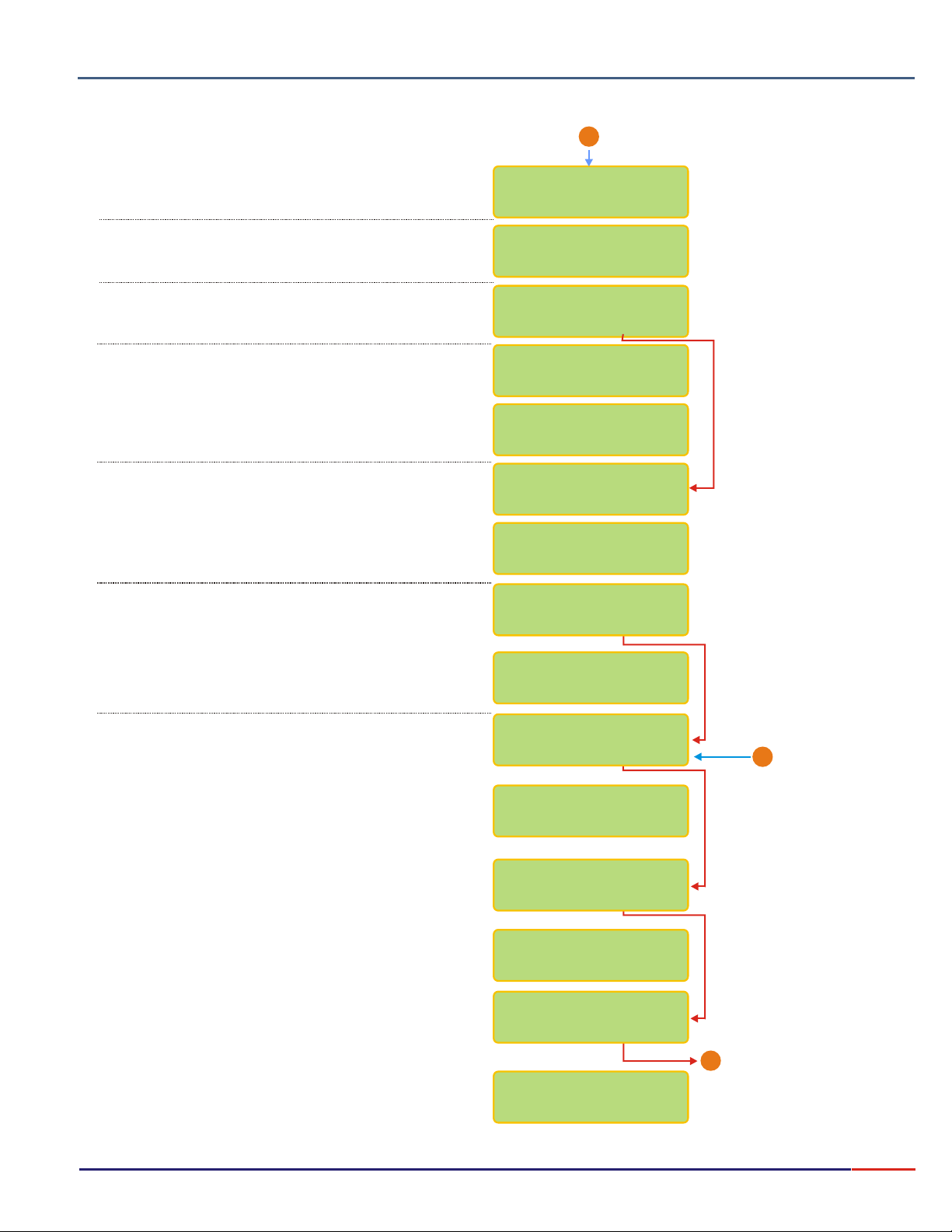
3.
8.5
Composição do produto
Equipment Operation mV - Set Up (cont.)
From Page 23
A
User can set up the instrument to store and display
the last Calibration date or Not.
User can set up the instrument to store and display
the last Check date would or Not.
User can change the last Electrode Change date.
This is not done Automatically
User can now insert the electrode change date into the
instrument. Use key to change numbers and
when finished, press key. If a mistake is made,
<ESCAPE>
press key to move back.
User can choose if instrument would Beep when Stability
is reached during Read Mode or Not.
User can choose if instrument would Beep on Keyboard
touch or Not.
User has the option to program the user name of the
operator.
In order to program the operator name press
key to change numbers and when finished, press
<ENTER> <ESCAPE>
key to move back.
<SELECT>
<ENTER>
<SELECT>
key. If a mistake is made, press
Calibration Date?
/ Yes No
Check Date?
/ Yes No
Change ORP Elec.?
/ Yes No
Inform new
electrode date:
12/06/2006
15:00:00
Beep Stability?
/ Yes No
Keyboard Beep?
/ Yes No
Operator ?
/ Yes No
Operator Name :
__________
During this sequence, user will be able to choose alarms
and also adjust it’s values.
Will be able to choose if RS232 is needed and if
connected to a PC or a Printer.
<SELECT>
Press key until desired option flashes, then
<ENTER>
press key to confirm the option chosen.
In order to adjust the values, refer to page 16.
User can choose to use RS 232 Output or not!
User can choose to use output for PC or Printer.
Max. Alarm ?
/ Yes No
Max. Value :
500mV ><
Min. Alarm ?
/ Yes No
Min. Value :
-500mV ><
RS232 Output?
/ Yes No
RS232 Output :
/ PC Printer
From Page 23
1
End
X
24
Page 26
Composição do produto
3.
8.5
User can program the PC or the Printer to be used at the RS 232 output, Speed Transmition and Printing modes, intervals
and Statistics.
Equipment Operation mV - Set Up (cont.)
From Page 24
A
RS232 Output:
/ PC Printer
CONT.: Print continuously (based on the
printing interval chosen)
Speed (100bps)
24 48 9612
Transm. Mode
./Cont Man./Stab.
Printing
Interval 2s ><
X
End
Veloc. (100bps)
24 48 9612
Transm. Mode
./Cont Man./Stab.
Printing
Interval 2s ><
Statistic?
/ Yes No
X
End
Prints the Read value just after
MAN.:
pressing key. But only after the
read value is stabilized (an arrow is displayed).
STAB.: Prints only one time, after the
reading is stabilized (an arrow is displayed).
<ENTER>
25
Page 27
3.
8.6
Composição do produto
Equipment Operation mV - Calibration
Press key until option flashes, then
<SELECT> mV
Press key until option flashes, then
Select Function
PH ºC CONC.mV
mV: /
Read
Set Up / Check
<SELECT> mV
press key to confirm the option chosen.
<ENTER>
press key to confirm the option chosen.
<ENTER>
Press key until option flashes, then
<SELECT> Read
press key to confirm the option chosen.
<ENTER>
mV: R / ead
Calibrate
ORP Elect.Chang:
00/00/00 08:00
Last Calib.Date:
00/00/00 08:00
Place Electrode
Sol.228mV @ 25ºC
Ready ?
WAIT
Sens.= 100%
Go to Sample!
Ready?
Press key until option flashes,
<SELECT> Calibrate
then press key to confirm the option
The last Electrode Change date and time will be
displayed. This date/time is changed manually during
Set Up operation.
The last Calibration date/time will be displayed!
Dip electrode into 225mV Standard Solution. This
solution value was chosen at Set Up Operation.
Then press key to confirm the option
chosen.
Wait.
The Sensibility of the Electrode will be displayed.
<ENTER>
<ENTER>
Go to Sample!
Ready?
202.0mV ABS <ENTER>
End Report?
/ NoYes
If user desires to exit the reading mode, press and hold
<ESCAPE>
following message will be displayed “End Report”.
This message shows in order for the user to inform the
software that the job ended, so the report can be
finalized.
for about 6seconds and before exiting the
202.0mV ABS
Go to Sample!
Ready?
-459mV REL
End Report?
/ NoYes
26
Page 28
3.
8.7
Composição do produto
Equipment Operation mV - Check
Press key until option flashes, then
Select Function
pH ºC CONC.mV
mV: R /
Set Up /
ead
Check
<SELECT> mV
press key to confirm the option chosen.
<ENTER>
Press key until option flashes, then
<SELECT> Check
press key to confirm the option chosen.
<ENTER>
Electrode
Check
ORP Elect.Chang:
00/00/00 08:00
Last Calib.Date:
00/00/00 08:00
Response Time?
/ Yes No
Place Electrode
Sol.228mV @ 25ºC
Ready ?
Wait
RESPONSE TIME
3s <ENTER>
The last Electrode Change date and time will be
displayed. This date/time is changed manually during
Set Up operation.
The last Calibration date/time will be displayed!
User will be able to check the Response Time of the Electrode.
Place Electrode
Sol.228mV @ 25ºC
Ready ?
Dip electrode into 228mV Standard
Solution. This solution value was
chosen at Set Up Operation.
Then press key to confirm
the option chosen.
Wait.
<ENTER>
Wait
Check
Result
Sens.: 100.0%
The Electrode Sensibility result will
be displayed. Depending on the
result, the program will inform how
to proceed.
If Sensibility is <80%
Electr.: Bad
Place Electrode
in 30% HCl
For 30 sec.
Persisting Bad
Contact OMEGA
Custom.Service
(800)872-9436
<ENTER>
If Sensibility is >=80 and <=95%
If Sensibility is >=95%
Electr.: Good Electr.: Very
Good
Wash Electrode
Ready ?
Remove the electrode
from the standard solution, wash it
using deionized water.
Then press key.<ENTER>
Wash Electrode
Ready ?
27
Page 29
3.
8.8
Composição do produto
Equipment Operation mV - Read
Press key until option flashes, then
Select Function
pH ºC CONC.mV
pH: /
Set Up / Check
mV: /
Read
Read
Calibrate
<SELECT> mV
press key to confirm the option chosen.
<ENTER>
Press key until option flashes, then
<SELECT> Read
press key to confirm the option chosen.
<ENTER>
Press key until option flashes, then
<SELECT> Read
press key to confirm the option chosen.
<ENTER>
Read :
/ Abs. Rel.
Go to Sample!
Ready?
202.0mV ABS 202.0mV ABS
End Report?
/ NoYes
If user desires to exit the reading mode, press and hold
<ESCAPE>
following message will be displayed “End Report”.
This message shows in order for the user to inform the
software that the job ended, so the report can be
finalized.
for about 6seconds and before exiting the
User will be able to choose between Absolute or
Relative Reading. Press key until option
flashes, then press key to confirm the
Read <ENTER>
option chosen.
Go to Sample!
Ready?
Go to Sample!
Ready?
-459mV REL
End Report?
/ NoYes
<SELECT>
28
Page 30
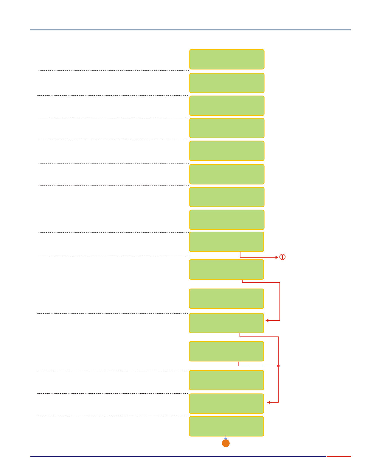
Composição do produto
3.
8.9
Press key until option flashes, then
press key to confirm the option chosen.
Press key until option flashes, then
press key to confirm the option chosen.
Equipment Operation ºC - Set Up
<SELECT> ºC
<ENTER>
<SELECT> Set Up
<ENTER>
Select Function
pH mV CONC.ºC
ºC : Read /
Set Up
A password is required to access the Set Up mode.
Press in sequence ,, .<SELECT> <ENTER> <ESCAPE>
User has the option to choose the desired language.
Press key until the desired option flashes,
then press key to confirm the option chosen.
User can choose between the following Reading Modes:
Continuous - Read continuously after time is set
Average - Reads the average after time is set
Hold - user must press key to Read
User can program the time between Readings. Refer to
Page 16 for instructions on how to adjust this time.
User can choose if desire to have Barr graph shown
above the Reading screen. When Bar Graph is
displayed, the information about Sensibility and Sample
Temperature will not be displayed!
User can now adjust the Minimum and Maximum
values for the Bar Graph.
<SELECT>
<ENTER>
This Screen is default and cannot be changed.
Select the Resolution by pressing key.
Option chosen will flash. Then press key to
confirm option chosen.
<ENTER>
User can program the display to show information like
Barr graph, Clock, Calibr., Check and Electr. Change
Dates and more.
<SELECT>
<ENTER>
PASSWORD
_ _ _
lANGUAGE: /
Port.
English/Spanish
Range
-2 to 12 ºC
Resolution
1 / 0.1
Reading Mode:
/Aver./HoldCont.
Reding Time:
1s <>
Config. Display?
/ Yes No
Bargraph ?
/ Yes No
Min.: 0pH
Max.: 14pH <<>>
Go to Page 30
User can choose to display date/clock on display,
when equipment is turned off.
User can adjust date and clock, if desired.
Use key to change numbers and when
<SELECT>
finished, press key. If a mistake is made,
press key to move back.
<ESCAPE>
User can set up the instrument to store and display
the last Calibration date or Not.
User can set up the instrument to store and display
the last Check date would or Not.
<ENTER>
Clock ?
/ Yes No
Adjust Clock?
/ Yes No
12/06/2006
15:00:00
Calibration Date
/ Yes No
Check Date
/ Yes No
B
Go to Page 30
29
Page 31
3.
8.9
Composição do produto
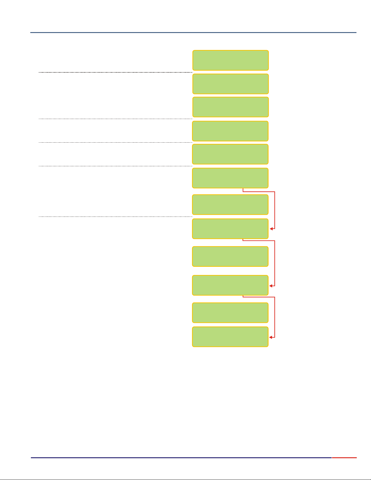
Equipment Operation ºC - Set Up (cont.)
User can change the last Electrode Change date.
This is not done Automatically
User can now insert the electrode change date into the
instrument. Use key to change numbers and
when finished, press key. If a mistake is made,
press key to move back.
<ESCAPE>
User can choose if instrument would Beep when Stability
is reached during Read Mode or Not.
User can choose if instrument would Beep on Keyboard
touch or Not.
User has the option to program the user name of the
operator.
In order to program the operator name press
key to change numbers and when finished, press
<ENTER> <ESCAPE>
key to move back.
During this sequence, user will be able to choose alarms
and also adjust it’s values.
Will be able to choose if RS232 is needed and if
connected to a PC or a Printer.
Press key until desired option flashes, then
<SELECT>
press key to confirm the option chosen.
<ENTER>
<SELECT>
<ENTER>
<SELECT>
key. If a mistake is made, press
Change Thermo ?
/ Yes No
Inform new
Thermo Date:
12/06/2006
15:00:00
Stability Beep?
/ Yes No
Keyboard Beep?
/ Yes No
Operator ?
/ Yes No
Operator Name :
__________
Max. Alarm?
/ Yes No
Max. Value:
100ºC <>
In order to adjust the values, refer to page 16.
User can choose to use RS 232 Output or not!
Min. Alarm?
/ Yes No
Min. Value:
0ºC <>
RS232 Output?
/ Yes No
30
Page 32
Composição do produto
3.
8.9
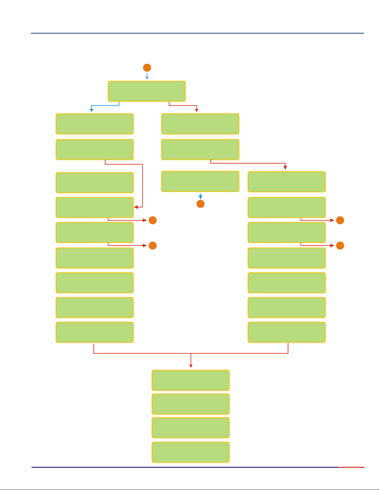
User can program the PC or the Printer to be used at the RS 232 output, Speed Transmition and Printing modes, intervals and
Statistics.
Equipment Operation ºC - Set Up (cont.)
From Page 30
A
RS232 Output:
CONT.: Print continuously (based on the
printing interval chosen)
Prints the Read value just after
MAN.:
pressing key. But only after the
read value is stabilized (an arrow is displayed).
STAB.: Prints only one time, after the
reading is stabilized (an arrow is displayed).
<ENTER>
Speed (100bps)
24 48 9612
Transm. Mode
./Cont Man./Stab
/ PC Printer
Speed (100bps)
24 48 9612
Printing Mode
./Cont Man./Stab
Printing
Interval 2s ><
Change Thermo?
/ Yes No
Confirm ?
/ Yes No
Thermostatize
Thermo @ 25ºC
Thermostatize
Thermo @ 25ºC
Intervalo de
Impressao 2s ><
X
End
End End
X X
End End
X X
Statistic?
/ Yes No
Change Thermo?
/ Yes No
Confirm ?
/ Yes No
Thermostatize
Thermo @ 25ºC
Thermostatize
Thermo @ 25ºC
WAIT WAIT
STABILIZING STABILIZING
IN CASE AN ERROR OCCUR DURING THERMOSTATIZATION
Verify Solution
Temperature
Verify Thermo
Persisting Error
Consult OMEGA
Cust.Service
(800)872-9436
<ENTER>
31
Page 33
Composição do produto
3.
8.10
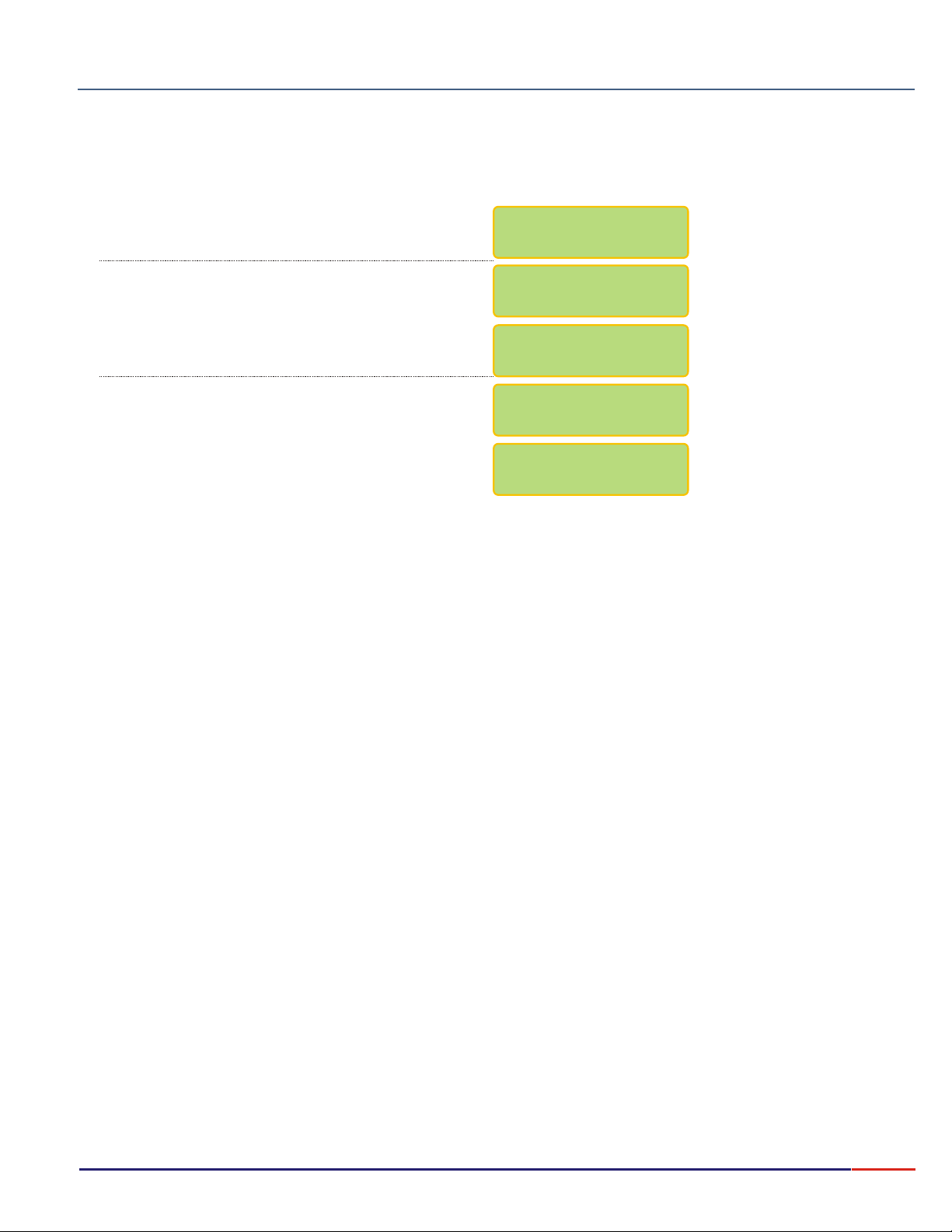
Press key until option flashes, then
press key to confirm the option chosen.
Press key until option flashes, then
press key to confirm the option chosen.
Equipment Operation ºC - Read
<SELECT> ºC
<ENTER>
<SELECT> Read
<ENTER>
Select Function
PH mV CONC.ºC
pH: /
Read
Set Up
Dip electrode into sample and when Ready, press
<ENTER>
If user desires to exit the reading mode, press and hold
<ESCAPE>
following message will be displayed “End Report”.
This message shows in order for the user to inform the
software that the job ended, so the report can be
finalized.
key to confirm.
for about 6seconds and before exiting the
Go to Sample!
Ready?
25.5 ºC
End Report?
/ Yes No
32
Page 34
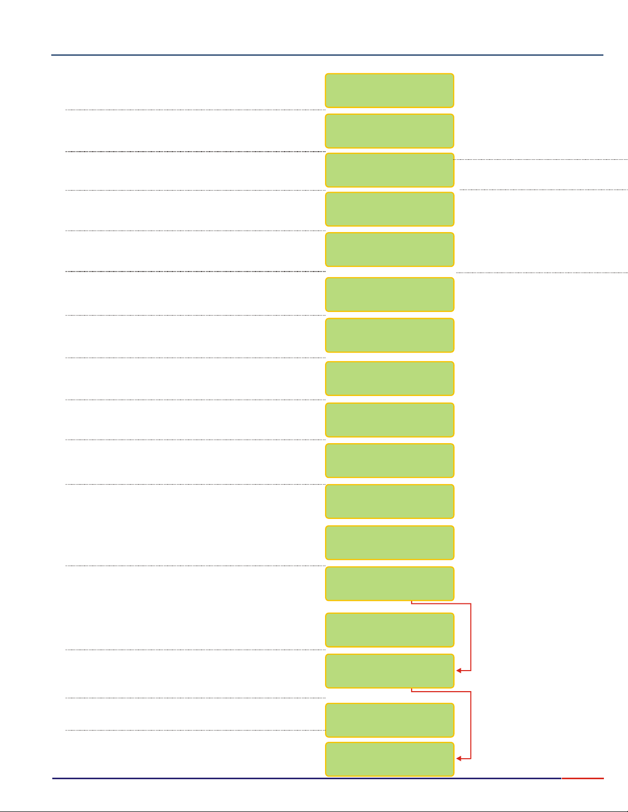
Equipment Operation Concentration - Set Up
3.
8.11
Press key until option flashes, then
press key to confirm the option chosen.
Press key until option flashes, then
press key to confirm the option chosen.
Composição do produto
<SELECT> Conc
<ENTER>
<SELECT> Set Up
<ENTER>
Select Function
pH mV ºC CONC.
Conc.: R /
/
ead
CheckSet Up
A password is required to access the Set Up mode.
Press in sequence ,, .<SELECT> <ENTER> <ESCAPE>
User has the option to choose the desired language.
Press key until the desired option flashes,
then press key to confirm the option chosen.
User can choose the desired element, refer to page 16
on how to modify the element.
User can choose the desired unit. Press key
until desired option flashes, then press key
to confirm.
Option to choose how many calibration points you need.
Press key until desired option flashes, then
press key to confirm chosen option.
<SELECT>
<ENTER>
<SELECT>
<ENTER>
This Screen is default and cannot be changed.
This Screen is default and cannot be changed.
This Screen is default and cannot be changed.
<SELECT>
<ENTER>
Password
_ _ _
Language: /
Port.
English/Spanish
Ion Selective:
Fluor F- ><
Units: mg/L
ppm
mol/L meq/L
Range
0.00 to 1900 ppm
PH Range
5 to 8 pH
Temperat.Range
0 to 80 ºC
Calibration
Points: /3/4/52
User can fully adjust the Standard values. In order to
get to know how to change the values, please refer to
Page 16 for instructions.
User can instruct the instrument to inform that
calibration is needed.
User can program the number of readings, before
instrument prompts for calibration. Refer to page 16
on how to adjust the number.
User can choose between Reference or Absolute
Temperature. Press key until desired option
flashes, then press key to confirm chosen
option.
User can choose to adjust the Temperature Coefficient.
Refer to page 16 on how to adjust this value.
User can choose between the following Reading Modes:
Continuous - Read continuously after time is set
Average - Reads the average after time is set
Hold - user must press key to Read<ENTER>
<SELECT>
<ENTER>
1º Point:
0.5 ppm <>
2º Point
5.0 ppm <>
Calibr.Inform.?
/ Yes No
Inform after
200 Readings<>
Temperature:
/ Ref. Absolute
Temp. Coefic.:
-0.13% / ºC ><
Read Mode:
Cont./Aver./Hold
33
Page 35
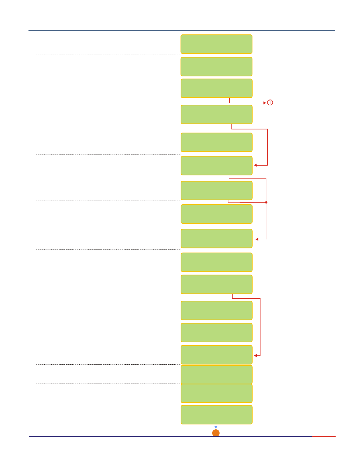
8.11
3.
Composição do produto
Equipment Operation Concentration - Set Up (cont.)
User can program the time between Readings. Refer to
Page 16 for instructions on how to adjust this time.
User has the option to choose the Sample Time, based
on ISE Process being used. Press key until
the desired option flashes, then press key to
confirm.
User can program the display to show information like
Barr graph, Clock, Calibr., Check and Electr. Change
Dates and more.
User can choose if desire to have Barr graph shown
above the Reading screen. When Bar Graph is
displayed, the information about Sensibility and Sample
Temperature will not be displayed!
User can now adjust the Minimum and Maximum
values for the Bar Graph.
User can choose to display date/clock on display,
when equipment is turned off.
User can adjust date and clock, if desired.
<SELECT>
<ENTER>
Reading Time:
1s <>
Sample Time:
1/2/3/4/5 min
Display ?
/ Yes No
Go to Page 35
Bargraph ?
/ Yes No
Min.: 0ppm >
Max.: 14ppm ><<
Clock ?
/ Yes No
ADJUST ?
/ Yes No
Use key to change numbers and when
<SELECT>
finished, press key. If a mistake is made,
press key to move back.
<ESCAPE>
User can set up the instrument to store and display
the last Calibration date or Not.
User can set up the instrument to store and display
the last Check date would or Not.
User can change the last Electrode Change date.
This is not done Automatically
User can now insert the electrode change date into the
instrument. Use key to change numbers and
when finished, press key. If a mistake is made,
<ESCAPE>
press key to move back.
User can choose if instrument would Beep when Stability
is reached during Read Mode or Not.
User can choose if instrument would Beep on Keyboard
touch or Not.
User has the option to program the user name of the
operator.
<ENTER>
<SELECT>
<ENTER>
12/06/2006
15:00:00
Calibration Date?
/ Yes No
Check Date?
/ Yes No
Change ISE ?
/ Yes No
Inform New
Electrode Date:
00/00/0000
00:00:00
Stability Beep?
/ Yes No
Keyboard Beep?
/ Yes No
Operator?
/ Yes No
In order to program the operator name press
key to change numbers and when finished, press
<ENTER> <ESCAPE>
key to move back.
key. If a mistake is made, press
<SELECT>
Operator Name:
_ _ _ _ _ _ _
B
Go to Pager 35
34
Page 36
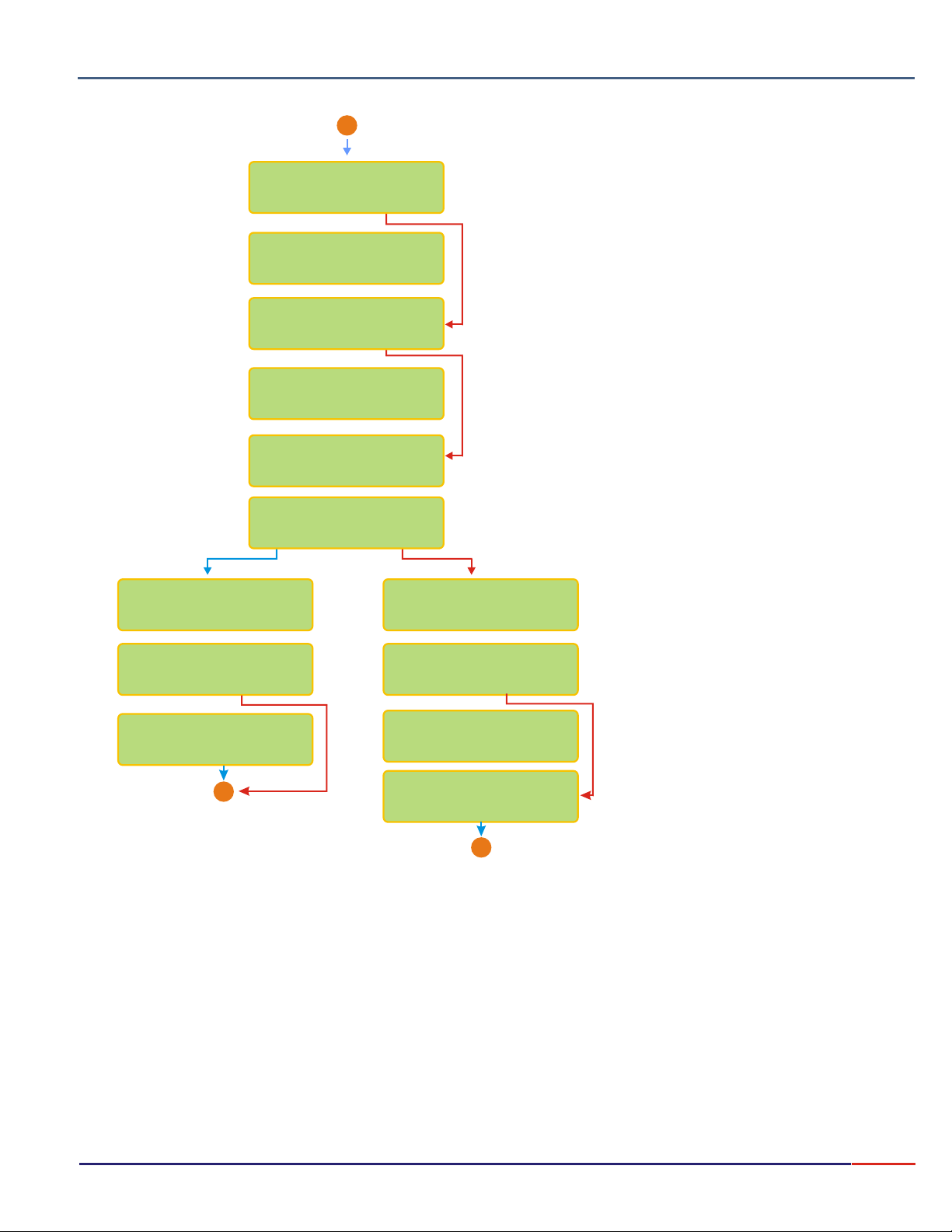
3.
8.11
Composição do produto
Equipment Operation Concentration - Set Up (cont.)
From Page 34
A
Max. Alarm ?
RS-232 Output?
RS232 Output:
Speed (100bps)
24 48 9612
Transmit. Mode
./Cont Man./Stab
Printing
Interval 2s ><
/ Yes No
Max. Value:
5 ppm ><
Min. Alarm?
/ Yes No
Min. Value:
0 ppm <>
/ Yes No
/ PC Printer
During this sequence, user will be able to choose alarms
and also adjust it’s values.
Will be able to choose if RS232 is needed and if
connected to a PC or a Printer.
<SELECT>
Press key until desired option flashes, then
<ENTER>
press key to confirm the option chosen.
In order to adjust the values, refer to page 16.
User can choose to use RS 232 Output or not!
User can choose between PC or Printer for output.
Speed (100bps)
24 48 9612
Printing Mode
./Cont Man./Stab
Printing
Interval 2s ><
CONT.: Print continuously (based on the
printing interval chosen)
Prints the Read value just after
MAN.:
pressing key. But only after the
read value is stabilized (an arrow is displayed).
STAB.: Prints only one time, after the
reading is stabilized (an arrow is displayed).
<ENTER>
X
End
Statistic?
/ Yes No
X
End
35
Page 37
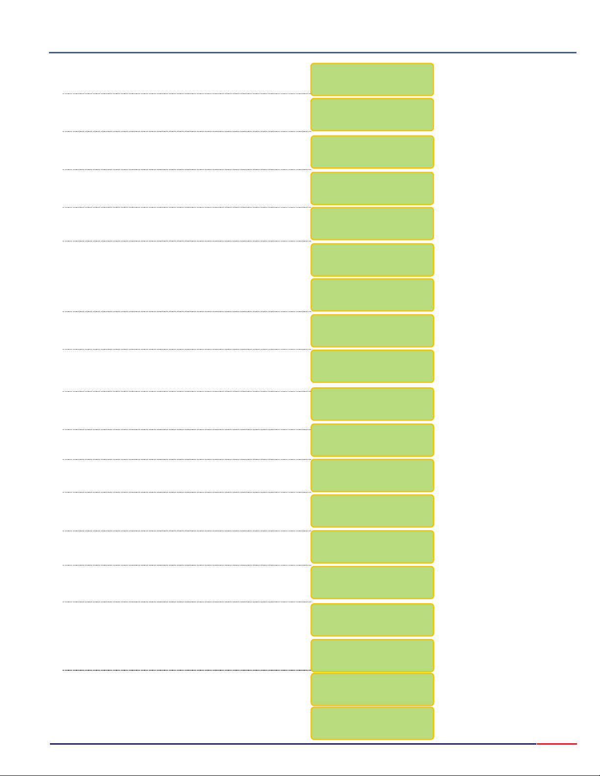
Equipment Operation Concentration - Calibration
3.
8.12
Press key until option flashes, then
press key to confirm the option chosen.
Press key until option flashes, then
press key to confirm the option chosen.
Press key until option flashes,
then press key to confirm the option
Composição do produto
<SELECT> Conc
<ENTER>
<SELECT> Read
<ENTER>
<SELECT> Calibrate
<ENTER>
Select Function
pH mV ºC CONC.
Conc.: /
Set Up /
Read
Check
Conc.: Read/
Calibrate
The last ISE Change date and time will be displayed.
This date/time is changed manually during Set Up
operation.
The last Calibration date/time will be displayed!
Dip electrode into 0.5mg/L Standard. This Standard
value was chosen at Set Up Operation.
Then press key when ready to continue
.
Wait.
Remove the electrode from 0.5mg/L Standard and
wash it using deionized water. Press key
when finished.
Dip electrode into 5.0mg/L Standard. This Standard
value was chosen at Set Up Operation.
Then press key to when ready to continue.
<ENTER>
<ENTER>
<ENTER>
ISE Change:
00/00/00 08:00
Last Calib.Date:
00/00/00 08:00
Place Electrode
Pt 1: 0.5 mg/L
READY?
WAIT
Wash Electrode
Ready ?
Place Electrode
Pt 2: 5.0 mg/L
READY?
Wait
At this moment, the Sensibility of the electrode will be
displayed!
Remove the electrode from 5.0mg/L Standard and
wash it using deionized water. Press key
when finished.
User is prompted to go to sample for Reading, if
desired, place ISE into sample, then press
key.
The display will show the element being measured, the
Sample Temperature, the Read value and the
reference temperature, if user had chosen Reference
Temperature during Set Up operation, otherwise the
Absolute (ABS) will be displayed, as shown!
Press key in order to adjust manually the
<SELECT>
Compensation temperature. Refer to page 16 for
instructions on how to adjust this value..
<ENTER>
<ENTER>
WAIT
Sens.=100.0%
Wash Electrode
Ready ?
Go to Sample!
Ready ?
F- 25.5ºC
0.1 mg/L @ 25ºC
100.0% 25.5ºC
190.2 mV ABS
Man. Temp. Comp.
25.0 ºC ><
End Report?
/ Yes No
If user desires to exit the
reading mode, press and hold
<ESCAPE>
6seconds and before exiting
the following message will be
displayed “End Report”.
This message shows in order
for the user to inform the
software that the job ended, so
The report can be finalized.
for about
36
Page 38
8.13
3.
Composição do produto
Equipment Operation Concentration - Check
Press key until option flashes, then
Select Function
pH mV ºC CONC.
mV: R /
Set Up /
ead
Check
Electrode
Check
<SELECT> Conc
press key to confirm the option chosen.
<ENTER>
Press key until option flashes, then
<SELECT> Check
press key to confirm the option chosen.
<ENTER>
Last ISE Chenge:
00/00/00 08:00
Last ChcekDate:
00/00/00 08:00
Response Time?
/ Yes No
Place Electrode
Pt 1: 0.5ppm
READY ?
WAIT
RESPONSE TIME
2s <ENTER>
The last ISE Change date and time will be displayed. This
date/time is changed manually during Set Up operation.
The last Calibration date/time will be displayed!
User can check the ISE response time. Press key
until the desired option flashes, then press key to
Confirm.
Dip electrode into 0.5mg/L
Place Electrode
Pt 1: 0.5ppm
WAIT
WASH ELECTRODE
READY ?
Place Electrode
Pt 2: 5.0ppm
READY ?
Standard. This Standard value
was chosen at Set Up Operation.
Then press key to
when ready to continue.
Wait.
Remove the electrode from 0.5mg/L
Standard and wash it using
deionized water. Press
key when finished.
Dip electrode into 5.0mg/L
Standard. This Standard value
was chosen at Set Up Operation.
Then press key to
when ready to continue.
<SELECT>
<ENTER>
<ENTER>
<ENTER>
<ENTER>
WAIT
Check Result
Pt 100 100C
<ENTER>
WASH ELECTRODE
READY ?
Wait.
37
Page 39

Equipment Operation Concentration - Read
3.
8.14
Press key until option flashes, then
press key to confirm the option chosen.
Press key until option flashes, then
press key to confirm the option chosen.
Press key until option flashes, then
press key to confirm the option chosen.
Press key until option flashes, then
press key to confirm the option chosen.
Composição do produto
<SELECT> Conc
<ENTER>
<SELECT> Check
<ENTER>
<SELECT> Read
<ENTER>
<SELECT> Read
<ENTER>
Select Function
pH mV ºC CONC.
mV: R /
Set Up /
Conc. /
ead
Check
Read
Set Up/Check
Conc. /
Read
Calibrate
Dip electrode into sample and when Ready, press
key to confirm.<ENTER>
This screen will be displayed only if a problem with the
Thermo is detected. Verify the thermo connection!
The display will show the element being measured, the
Sample Temperature, the Read value and the reference
temperature, if user had chosen Reference Temperature
during Set Up operation, otherwise the Absolute (ABS)
will be displayed, as shown!
If user desires to exit the reading mode, press and hold
<ESCAPE>
following message will be displayed “End Report”.
This message shows in order for the user to inform the
software that the job ended, so the report can be
finalized.
for about 6seconds and before exiting the
Go to Sample!
Ready ?
Attention
Verify ATC
F- 25.5ºC
0.1 mg/L 25.5ºC
100.0% 25.5ºC
3.591pH @ 25ºC
Man. Temp. Comp.
25.0ºC <>
End Report?
/ Yes No
38
Page 40

Service and Maintenance
9.
3.
Equipment Maintenance
For instrument cleaning, use isopropilic alcohol, using a clean tissue and drying it just after. After this operation, it is
suggested to use a clear wax using a fine tissue and wax the instrument body but not the tactile membrane keyboard.
Remove excess wax from the body, polishing it.
Electrodes Maintenance
1 - For storage purpose the electrodes must be dipped at the same electrolyte reference solution as used internally at the
electrode, with Electrolyte Fill Hole (9) closed.
2 - In order to avoid Reading errors, the Bulb (1) and the Punctual Ceramic (3), must be always cleaned.
3 - For cleaning purpose, wash the electrode using neutral detergent, rubbing with your own fingers and rinse it using
plenty of distilled water. Dip the electrode for about 15 minutes in Thiourea Solution and after this, dip it for 15
minutes in PEPSIN Solution.
4 - If necessary dip it for 5 minutes in HCl 0.1N and for 5 minutes in NaOH 0.1N. Repeat this operation and then rest the
electrode for 30 minutes in 3 MKCl.
5 - In case noticed that the internal Electrolyte Reference is hazy or contaminated, replace it by removing the internal
reference, using a syringe through Fill Hole (9) and wash the electrode internally using distilled water. Repeat this
operation 3 times, then refill the electrode using the appropriate internal reference, depending on the electrode type.
6 - The membrane (1) must be cleaned manually using lint free absorbent paper. Any grease should be removed using
benzine, or any other solvent.
7 - For though dirt, use Chloridric Acid 0.1N and or suphochromic solution. After this, leave the bulb of the electrode
submersed for 12 hours, then dip it in 3 MKCI solution.
8 - Dehydrated membranes, must be dipped for about 30 seconds in HF (1-2%) solution, fro renewal of the gel cap. After
this, dip the bulb for 12 hours in 3 MKCI solution.
Composição do produto
39
Page 41

WARRANTY/DISCLAIMER
OMEGA ENGINEERING, INC. warrants this unit to be free of defects in materials and workmanship for a
period of 13 months from date of purchase. OMEGA’s WARRANTY adds an additional one (1) month
grace period to the normal one (1) year product warranty to cover handling and shipping time. This
ensures that OMEGA’s customers receive maximum coverage on each product.
If the unit malfunctions, it must be returned to the factory for evaluation. OMEGA’s Customer Service
Department will issue an Authorized Return (AR) number immediately upon phone or written request.
Upon examination by OMEGA, if the unit is found to be defective, it will be repaired or replaced at no
charge. OMEGA’s WARRANTY does not apply to defects resulting from any action of the purchaser,
including but not limited to mishandling, improper interfacing, operation outside of design limits,
improper repair, or unauthorized modification. This WARRANTY is VOID if the unit shows evidence of
having been tampered with or shows evidence of having been damaged as a result of excessive corrosion;
or current, heat, moisture or vibration; improper specification; misapplication; misuse or other operating
conditions outside of OMEGA’s control. Components in which wear is not warranted, include but are not
limited to contact points, fuses, and triacs.
OMEGA is pleased to offer suggestions on the use of its various products. However,
OMEGA neither assumes responsibility for any omissions or errors nor assumes liability for any
damages that result from the use of its products in accordance with information provided by
OMEGA, either verbal or written. OMEGA warrants only that the parts manufactured by the
company will be as specified and free of defects. OMEGA MAKES NO OTHER WARRANTIES OR
REPRESENTATIONS OF ANY KIND WHATSOEVER, EXPRESSED OR IMPLIED, EXCEPT THAT OF
TITLE, AND ALL IMPLIED WARRANTIES INCLUDING ANY WARRANTY OF MERCHANTABILITY
AND FITNESS FOR A PARTICULAR PURPOSE ARE HEREBY DISCLAIMED. LIMITATION OF
LIABILITY: The remedies of purchaser set forth herein are exclusive, and the total liability of
OMEGA
indemnification, strict liability or otherwise, shall not exceed the purchase price of the
co mponent u pon which liab ility is base d. In n o ev ent shall OMEGA be l iable for
consequential, incidental or special damages.
CONDITIONS: Equipment sold by OMEGA is not intended to be used, nor shall it be used: (1) as a “Basic
Component” under 10 CFR 21 (NRC), used in or with any nuclear installation or activity; or (2) in medical
applications or used on humans. Should any Product(s) be used in or with any nuclear installation or
activity, medical application, used on humans, or misused in any way, OMEGA assumes no responsibility
as set forth in our basic WARRANTY/DISCLAIMER language, and, additionally, purchaser will indemnify
OMEGA and hold OMEGA harmless from any liability or damage whatsoever arising out of the use of the
Product(s) in such a manner.
with r
espect to this order, whether based on contract, warranty, negligence,
RETURN REQUESTS/INQUIRIES
Direct all warranty and repair requests/inquiries to the OMEGA Customer Service Department. BEFORE
RETURNING ANY PRODUCT(S) TO OMEGA, PURCHASER MUST OBTAIN AN AUTHORIZED RETURN
(AR) NU M B ER FR O M OMEGA’S CU STOME R SERV I CE DE PART M ENT (I N ORDER TO AVOID
PROCESSING DELAYS). The assigned AR number should then be marked on the outside of the return
package and on any correspondence.
The purchaser is responsible for shipping charges, freight, insurance and proper packaging to prevent
breakage in transit.
FOR WARRANTY
following information available BEFORE
contacting OMEGA:
1. Purchase Order number under which the product
was PURCHASED,
2. Model and serial number of the product under
warranty, and
3. Repair instructions and/or specific problems
relative to the product.
OMEGA’s policy is to make running changes, not model changes, whenever an improvement is possible. This affords
our customers the latest in technology and engineering.
OMEGA is a registered trademark of OMEGA ENGINEERING, INC.
© Copyright 2010 OMEGA ENGINEERING, INC. All rights reserved. This document may not be copied, photocopied,
reproduced, translated, or reduced to any electronic medium or machine-readable form, in whole or in part, without the
prior written consent of OMEGA ENGINEERING, INC.
RETURNS, please have the
FOR NON-WARRANTY REPAIRS,
for current repair charges. Have the following
information available BEFORE contacting OMEGA:
1. Purchase Order number to cover the COST
of the repair,
2. Model and serial number of the product, and
3. Repair instructions and/or specific problems
relative to the product.
consult OMEGA
Page 42

Where Do I Find Everything I Need for
Process Measurement and Control?
OMEGA…Of Course!
Shop online at omega.com
SM
TEMPERATURE
Thermocouple, RTD & Thermistor Probes, Connectors, Panels & Assemblies
Wire: Thermocouple, RTD & Thermistor
Calibrators & Ice Point References
Recorders, Controllers & Process Monitors
Infrared Pyrometers
PRESSURE, STRAIN AND FORCE
Transducers & Strain Gages
Load Cells & Pressure Gages
Displacement Transducers
Instrumentation & Accessories
FLOW/LEVEL
Rotameters, Gas Mass Flowmeters & Flow Computers
Air Velocity Indicators
Turbine/Paddlewheel Systems
Totalizers & Batch Controllers
pH/CONDUCTIVITY
pH Electrodes, Testers & Accessories
Benchtop/Laboratory Meters
Controllers, Calibrators, Simulators & Pumps
Industrial pH & Conductivity Equipment
DATA ACQUISITION
Data Acquisition & Engineering Software
Communications-Based Acquisition Systems
Plug-in Cards for Apple, IBM & Compatibles
Data Logging Systems
Recorders, Printers & Plotters
HEATERS
Heating Cable
Cartridge & Strip Heaters
Immersion & Band Heaters
Flexible Heaters
Laboratory Heaters
ENVIRONMENTAL
MONITORING AND CONTROL
Metering & Control Instrumentation
Refractometers
Pumps & Tubing
Air, Soil & Water Monitors
Industrial Water & Wastewater Treatment
pH, Conductivity & Dissolved Oxygen Instruments
M4509/0908
 Loading...