

Page 1
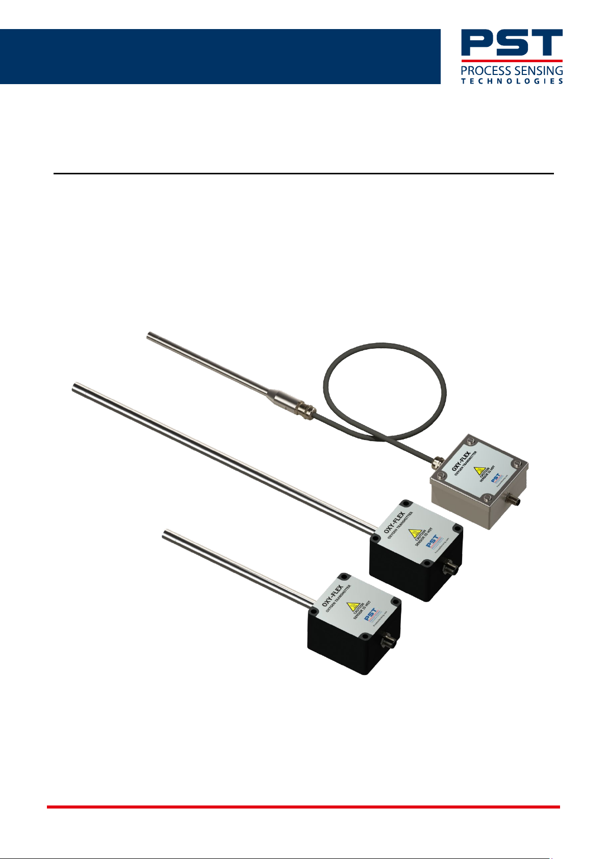
OXY-FLEX Series Oxygen Transmitter
User Manual PST-UM-1400-EN-03
Page 2

OXY-FLEX Series Oxygen Transmitter User Manual PST-UM-1400-EN-03
Issue No. Description Date
01 Issue 01 to the new PST style guide. October 2021
02
03
Metadata update, no information change. Issue update
required.
Update to the supply current in the electrical table.
Addition of the compliance appendix.
November 2021
March 2022
Page 2 of 34
Page 3

OXY-FLEX Series Oxygen Transmitter User Manual PST-UM-1400-EN-03
Table of Contents
Definitions ..................................................................................................................................................................... 5
Abbreviations ............................................................................................................................................................... 5
Introduction .................................................................................................................................................................. 6
3.1 Intended use of the OXY-FLEX Series Oxygen Transmitter ................................................................. 6
3.2 Product Overview ................................................................................................................................................ 6
Safety Instructions ..................................................................................................................................................... 7
Technical Description ................................................................................................................................................ 8
5.1 External Dimensions ........................................................................................................................................... 8
5.2 Performance Specifications ............................................................................................................................10
5.3 Mechanical Specifications ...............................................................................................................................11
5.4 Electrical Input / Output Specifications .....................................................................................................11
5.5 Operating Conditions .......................................................................................................................................11
Installation...................................................................................................................................................................12
6.1 Mounting Instructions ......................................................................................................................................12
6.2 Electrical Connections ......................................................................................................................................13
6.3 Connector Housing ............................................................................................................................................14
6.4 System Block Diagram ......................................................................................................................................14
6.5 PCB Layout ...........................................................................................................................................................15
Initial Startup ..............................................................................................................................................................15
7.1 Commissioning Checks.....................................................................................................................................15
7.2 Switching ON the Device .................................................................................................................................16
7.3 First Time Calibration .......................................................................................................................................16
System Configuration ..............................................................................................................................................17
8.1 Setting the Output Type ..................................................................................................................................18
8.2 Setting the Calibration Type and Measurement Range ........................................................................19
8.3 Digital Variant – RS232 Output ....................................................................................................................20
8.4 Menu Security Password .................................................................................................................................21
8.5 Automatic Calibration Value ..........................................................................................................................21
8.6 Variable Output Filtering (T
Averaging) ...................................................................................................21
d
8.7 Analog Output Minimum and Maximum Ranges ....................................................................................22
8.8 Analog Variants ...................................................................................................................................................24
Operation ....................................................................................................................................................................24
9.1 Operating Tips .....................................................................................................................................................24
9.2 RS232 Operation ................................................................................................................................................24
9.3 Continuous Data Streaming ...........................................................................................................................24
9.4 Menu Screens ......................................................................................................................................................25
Maintenance ...............................................................................................................................................................26
Page 3 of 34
Page 4

OXY-FLEX Series Oxygen Transmitter User Manual PST-UM-1400-EN-03
10.1 Calibrating ............................................................................................................................................................26
10.2 Automatic Calibration ......................................................................................................................................27
10.3 Manual Calibration ............................................................................................................................................27
10.4 Error Conditions .................................................................................................................................................28
10.5 Cleaning .................................................................................................................................................................28
10.6 Disposal..................................................................................................................................................................28
Appendix A – Menu Structure ..............................................................................................................................29
Appendix B – Quality, Recycling & Warranty Information ........................................................................33
Page 4 of 34
Page 5

OXY-FLEX Series Oxygen Transmitter User Manual PST-UM-1400-EN-03
Definitions
The following definitions apply to WARNINGS, CAUTIONS, and NOTES used throughout this guide.
WARNING:
The warning symbol is used to indicate instructions that, if they are not followed, can result in minor,
serious or even fatal injuries to personnel.
CAUTION:
The caution symbol is used to indicate instructions that, if they are not followed, can result in
damage to the equipment (hardware and/or software), or a system failure occurring.
NOTE: Highlights an essential operating procedure, condition, or statement.
Abbreviations
The following abbreviations are used in the guide:
AC Alternating Current
DC Direct Current
°C Degrees Celsius
°F Degrees Fahrenheit
mA Milliampere
PLC Programmable Logic Controller
GND Ground
LED Light-emitting Diode
PC Personal Computer
PCB Printed Circuit Board
Page 5 of 34
Page 6
OXY-FLEX Series Oxygen Transmitter User Manual PST-UM-1400-EN-03
Introduction
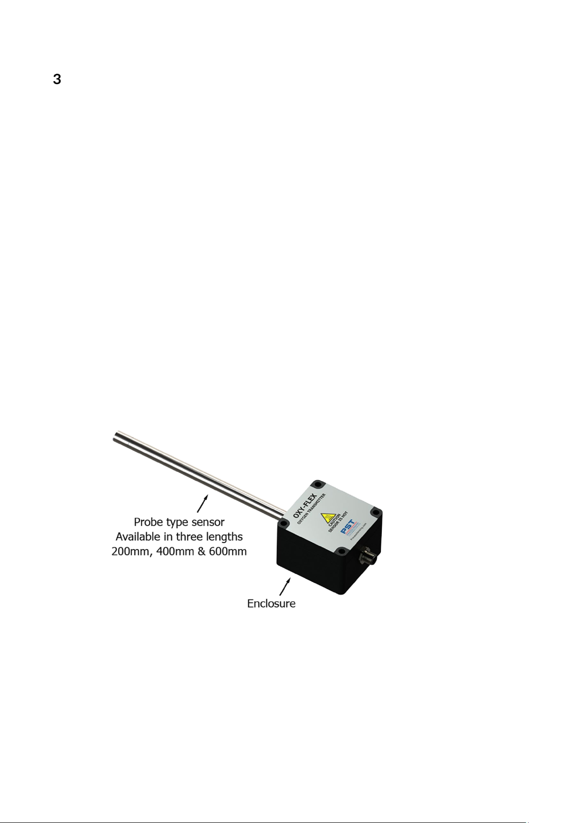
This manual is applicable to the following OXY-FLEX series oxygen transmitters.
XZR200 with aluminum housing (Probe mounted on housing).
XZR201 with aluminum housing (Probe connected via cable).
XZR210 with stainless-steel housing (Probe mounted on housing).
XZR211 with stainless-steel housing (Probe connected via cable).
3.1 Intended use of the OXY-FLEX Series Oxygen Transmitter
The OXY-FLEX Series of oxygen transmitters are designed to determine the oxygen concentration in
air or inert gas mixtures in areas that are not easily accessible or in closed systems, such as ventilation
pipes, flues, and containers.
The OXY-FLEX Series high-temperature oxygen transmitter is designed for use in air or inert gas
mixtures with temperatures of -100 °C /-148 °F to +400 °C / 750 °F maximum.
The actual oxygen sensor is mounted in the tip of the stainless-steel probe and is protected by a
stainless-steel sintered cap which acts as a large particulate filter.
The die-cast aluminum or stainless steel housing accommodates the electronics.
3.2 Product Overview
The OXY-FLEX Series of transmitters are housed in a sealed, die-cast aluminum or stainless-steel
enclosure with an attached oxygen sensor probe and M12, 8 Pin, A Coded connector.
Main Components
Page 6 of 34
Page 7

OXY-FLEX Series Oxygen Transmitter User Manual PST-UM-1400-EN-03
Safety Instructions
• This equipment may only be installed by a suitably qualified technician in accordance with the
instructions in this manual and any applicable standards associated with the country or
industry.
• Failure to correctly adhere to these instructions may result in severe injury or death, and in
this regard, the manufacturer will not be held liable.
• This equipment may only be operated and maintained by trained technical personnel.
The technical personnel must strictly adhere to the instructions given in this manual, and any
prevailing standards/certificates (depending on application).
• The operator may only perform modifications and repairs to the equipment/system with the
written approval of the manufacturer.
• Do NOT operate damaged equipment.
• If faults cannot be rectified, the equipment must be taken out of service and secured against
unintentional commissioning.
Page 7 of 34
Page 8
OXY-FLEX Series Oxygen Transmitter User Manual PST-UM-1400-EN-03
Technical Description
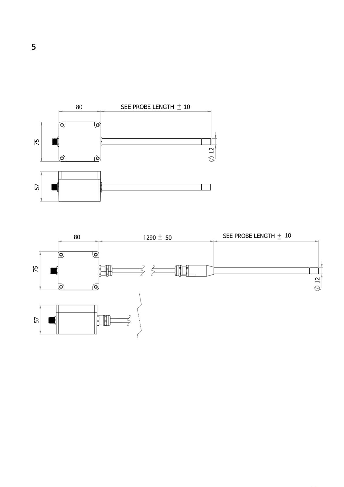
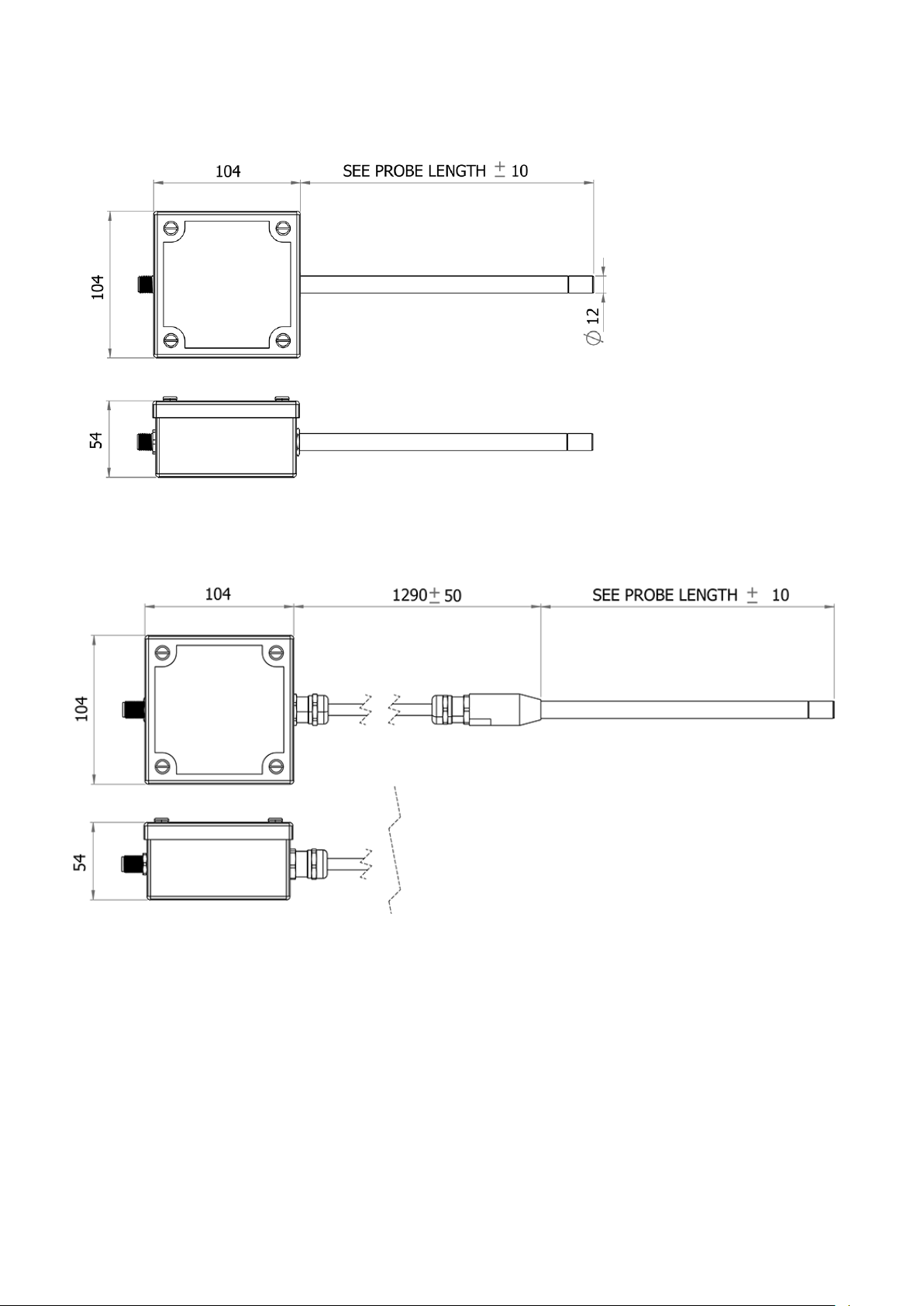
5.1 External Dimensions
Dimensions are in mm unless otherwise stated.
XZR200 with aluminum housing
XZR201 with aluminum housing with probe connected via shielded cable
Page 8 of 34
Page 9
OXY-FLEX Series Oxygen Transmitter User Manual PST-UM-1400-EN-03
XZR210 with stainless-steel housing
XZR211 with stainless-steel housing with probe connected via shielded cable
Page 9 of 34
Page 10

OXY-FLEX Series Oxygen Transmitter User Manual PST-UM-1400-EN-03
5.2 Performance Specifications
Performance
Measurement Technology Zirconia
Gas Oxygen
Measurement Range 0.1…25 % or 0.1…100 %
Output Resolution
Accuracy (0-25%)
Accuracy (0-100%)
0.01 V, 0.01 mA or 0.01 % O
< 0.5 % O
< 1 % O
2
2
Response Time (T10-90) < 15 seconds
Repeatability < 0.5 %
Sample Flow Rate 0…10 m/sec
Sample Flow Effect (calibrated @ 0.5
l/min)
±0.1 % O
(0 to 1 l/min)
2
Sample Pressure Atmospheric*
Sample Temperature Up to + 400 °C
Background Gas
Air, N
CO2, Ar or combustion gas
2,
2
*The OXY-FLEX Series of transmitters are designed to be operated at atmospheric pressures.
However, it is possible to measure in the range 0.1 to 25% O
at pressures up to 3 barg (43.5 psig)
2
without damage to the unit.
The unit will require calibration at the operating pressure, and a separate pressure transducer feeding
into the control system may be required.
Page 10 of 34
Page 11
OXY-FLEX Series Oxygen Transmitter User Manual PST-UM-1400-EN-03
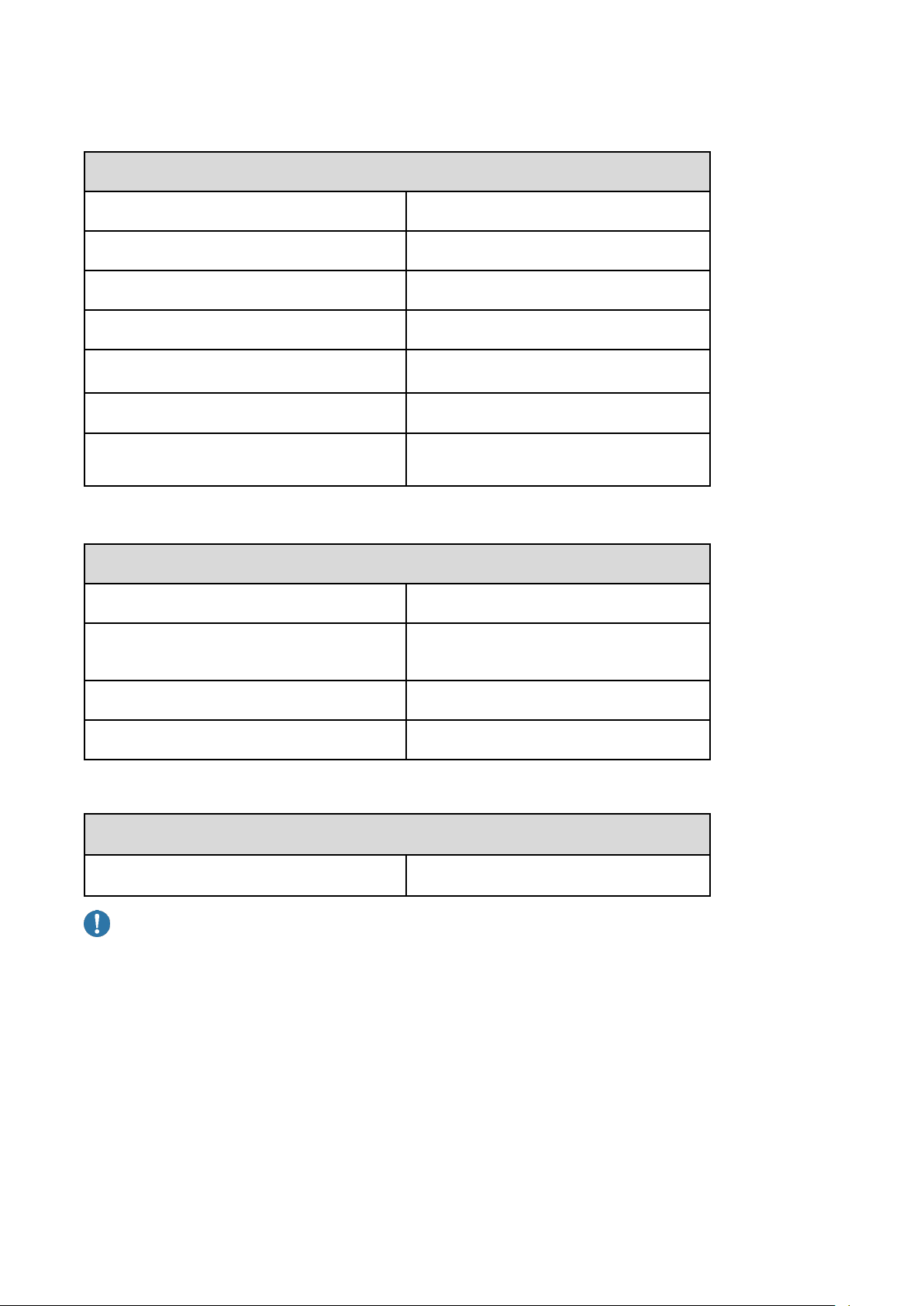
5.3 Mechanical Specifications
Mechanical Specifications
Warm Up Time Approx. 10 minutes
Probe Dimensions 220, 400 or 600 mm (length) ø12 mm
Weight < 0.5 kg
Wetted Materials Stainless-steel
Process Connection
Ingress Protection IP66
Housing Material
12 mm Swagelok® compression fitting
or equivalent required
Waterproof die-cast aluminum or
stainless-steel housing
5.4 Electrical Input / Output Specifications
Electrical Input / Output
Supply Voltage 24 V DC, ±10 %
Supply Current
Analog Outputs 0…10 V DC, 4…20 mA
Comms Output RS232
< 1 A Operating @ 24 V DC
< 2 A Start-up @ 24 V DC
5.5 Operating Conditions
Operating Conditions
Ambient Temperature (Enclosure) -10 to +85 °C (14 to +185 °F)
CAUTION: Risk of damage!
Prolonged operation below 0.1 % O2 can damage the sensing element.
Page 11 of 34
Page 12
OXY-FLEX Series Oxygen Transmitter User Manual PST-UM-1400-EN-03
Installation
Your equipment must be installed correctly by trained technical personnel to ensure the best
performance.
CAUTION: Risk of damage!
Protect the device from accidental shock or vibration as this may damage the board.
6.1 Mounting Instructions
Dimensions are in mm unless otherwise stated.
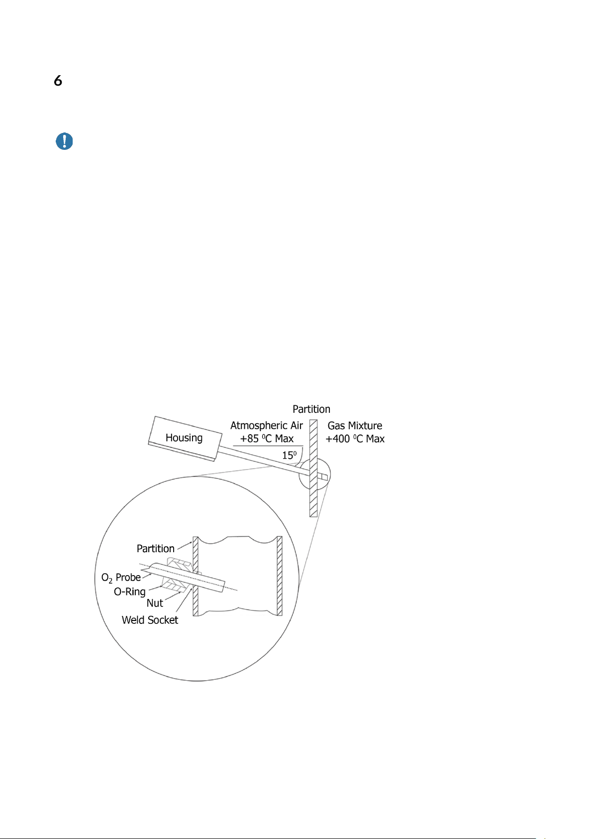
Transmitters with probe attached directly to the housing (XZR200, XZR210): are typically mounted to
the process gas / flue as shown in the diagram below.
The recommended 15° down angle on the probe is intended to eliminate the possibility of moisture
collecting in the probe tip during combustion applications.
In dry applications, this 15° angle is not necessary.
Transmitters with probe connected via shielded cable (XZR201, XZR211): the probe is typically
mounted to the process as shown in the diagram below.
Probe mounting & orientation
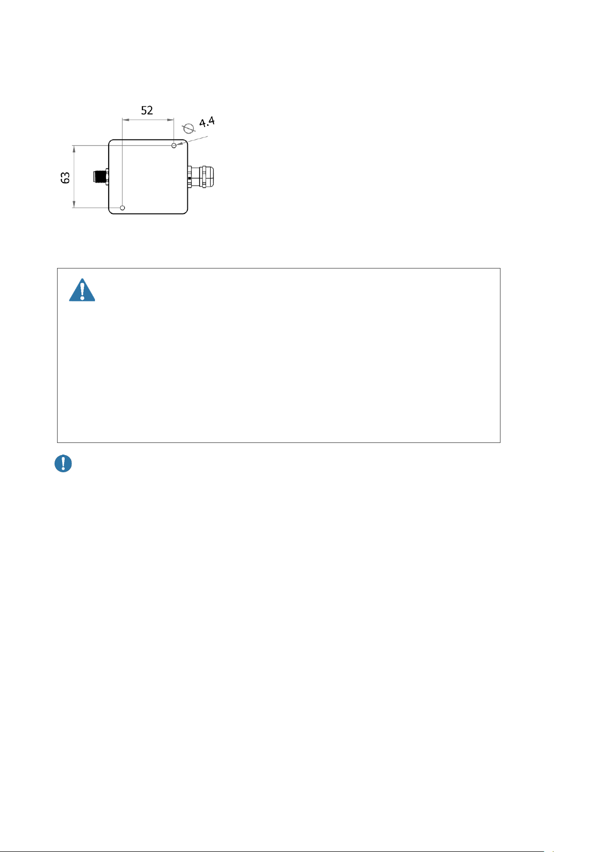
The XZR200, XZR201 housing can be mounted to a flat surface using the mounting holes.
TheXZR210, XZR211 housing cannot be mounted directly to a flat surface.
The customer must use a suitable bracket of their own design.
Page 12 of 34
Page 13
OXY-FLEX Series Oxygen Transmitter User Manual PST-UM-1400-EN-03
Aluminum enclosure mounting holes (XZR200, XZR210)
Mounting holes are accessible after removal of the housing lid.
6.2 Electrical Connections
WARNING: Danger of Death
All wiring MUST be in accordance with the National Electrical Code and any local
codes, ordinances, and regulations.
Disconnect and lockout power before connecting the equipment to the power
supply.
The device wiring should be in a separate conduit.
Do NOT install wiring in any conduit or junction boxes with high voltage wiring.
CAUTION: Risk of damage!
Do not install the device suspended from the cable.
Avoid exerting excessive tensile force on the cable.
Page 13 of 34
Page 14
OXY-FLEX Series Oxygen Transmitter User Manual PST-UM-1400-EN-03
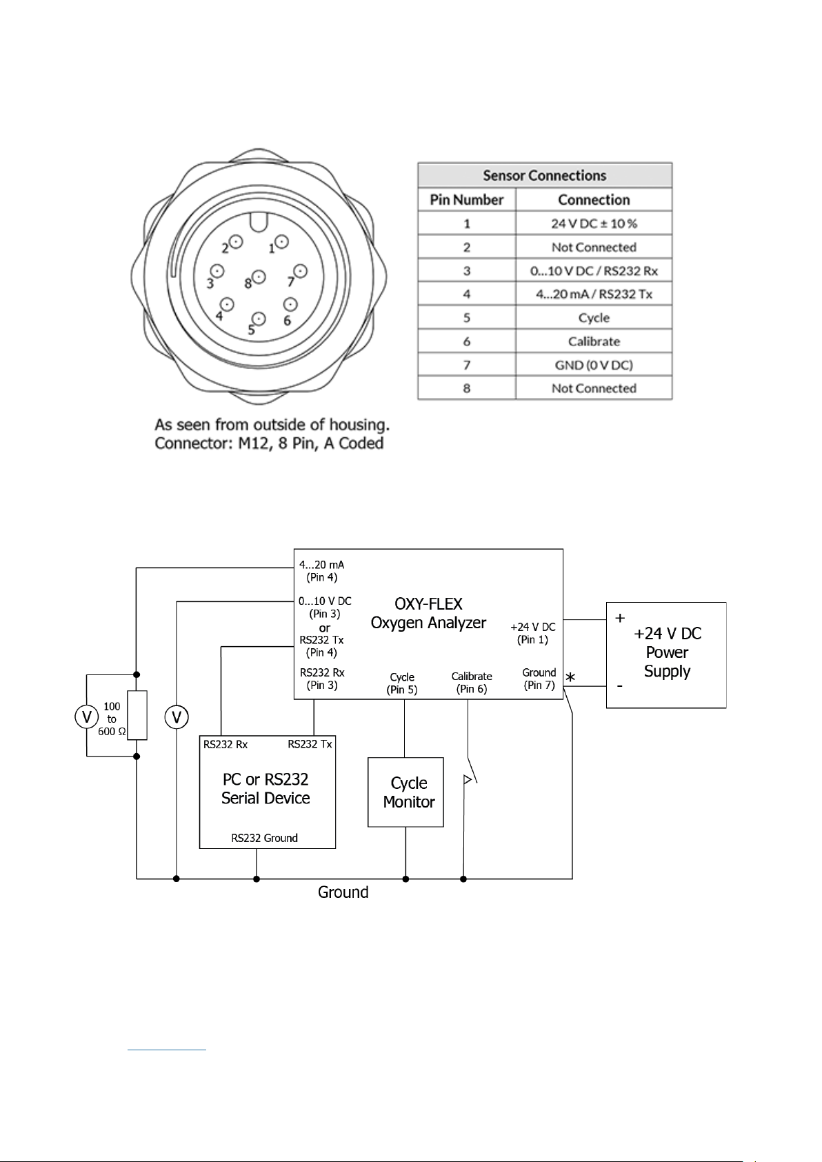
6.3 Connector Housing
6.4 System Block Diagram
*
Output pins 3 and 4 are both referenced to the power supply 0 V DC (pin 7).
Due to high current flow in the supply GND, when monitoring the 0…10 V DC output (pin 6), it is
recommended that a separate GND wire for the measurement system is taken from pin 7.
This removes errors due to voltage drops in the power supply connections.
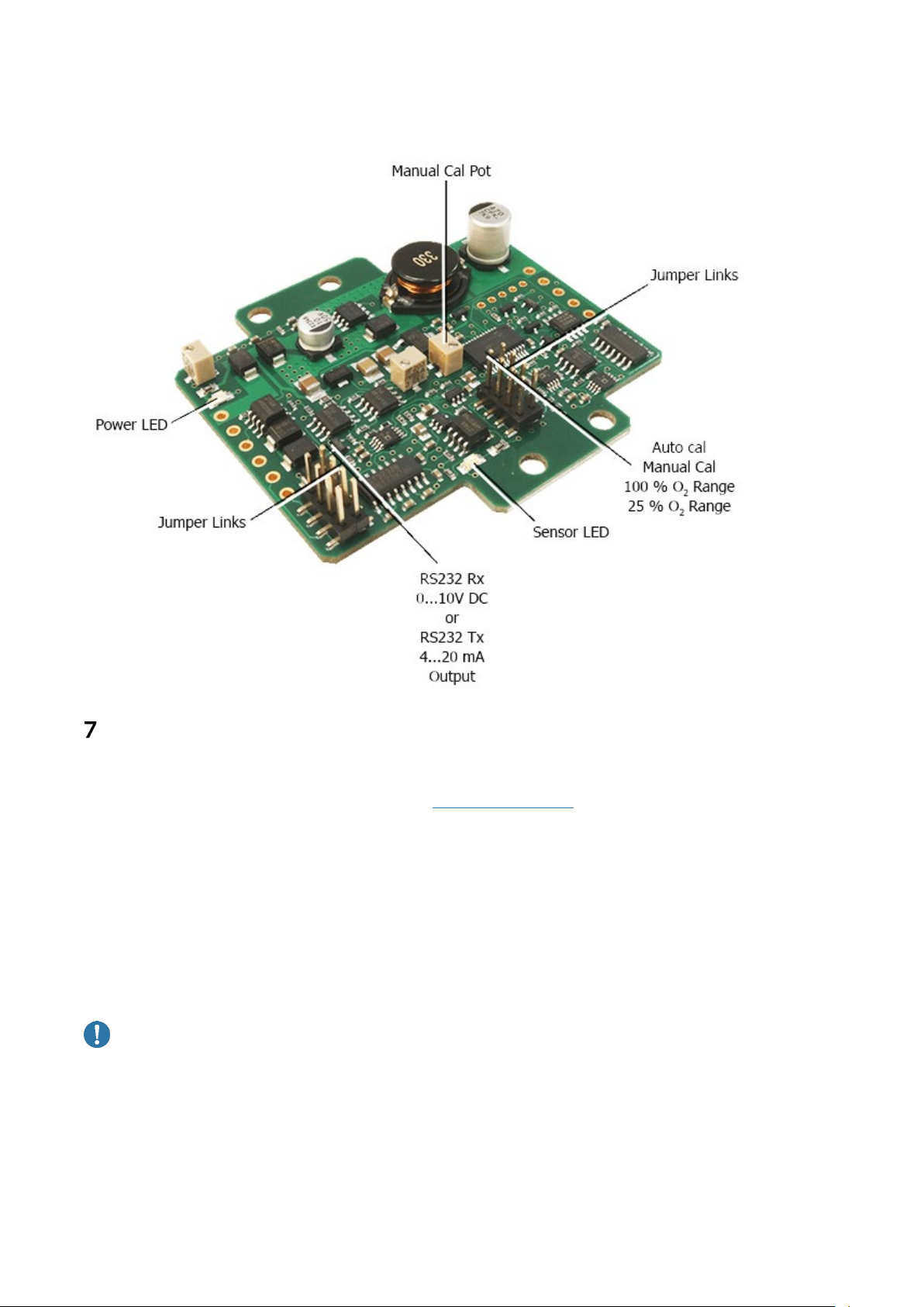
Assignment of output pins 3 and 4 selectable by altering the position of the jumper links on the PCB;
refer to PCB Layout in this document.
Page 14 of 34
Page 15
OXY-FLEX Series Oxygen Transmitter User Manual PST-UM-1400-EN-03
6.5 PCB Layout
Initial Startup
7.1 Commissioning Checks
Before commissioning the equipment, read the Safety Instructions contained in this document.
Complete the following essential tasks BEFORE switching the system ON for the first time:
1. Ensure compliance with the permissible installation position.
2. Verify the device is mounted securely and correctly.
3. Verify the device and wiring are all undamaged.
4. Ensure the cables are strain-free.
5. Ensure the device is connected correctly, with all inputs and outputs complete and that all
connectors are seated correctly, and all screw terminals are tightened.
CAUTION: Risk of damage!
Test the power supply to ensure it is “24 V DC ± 10 %” before wiring to the board.
Failure to test the suitability of the power supply BEFORE first power on can result in
irreversible product damage that is NOT covered by warranty.
Page 15 of 34
Page 16

OXY-FLEX Series Oxygen Transmitter User Manual PST-UM-1400-EN-03
7.2 Switching ON the Device
When the device is initially powered ON:
The Red LED illuminates solid to indicate power is being supplied to the
interface.
The Green LED blinks rapidly then goes OFF to indicate that the
microprocessor is operational.
NOTE: LEDs are only visible when the lid is removed from the transmitter housing.
NOTE: If a fault is detected, an error is displayed (RS232 variant), or the analog output will remain at
4 mA or 0 V.
Refer to Error Conditions contained in this document.
If the error condition persists, switch the device OFF and contact [email protected]
7.3 First Time Calibration
Calibration, or re-referencing, is required when the product is powered ON in the process application
for the first time.
Refer to Calibrating contained in this document.
Page 16 of 34
Page 17

OXY-FLEX Series Oxygen Transmitter User Manual PST-UM-1400-EN-03
System Configuration
The OXY-FLEX Series of transmitters can be configured to output measuring ranges of 0.1…25 % O2
and 0.1…100 % O2; the entire measurement range is linear in both cases.
NOTE: Factory default is 0…25 % O
When configured for 0…100 % O
with linear 4…20 mA and 0…10 V DC outputs.
2
, the analog output ranges can be customized to suit the application.
2
Refer to Setting the Calibration Type and Measurement Range contained in this document.
The outputs can be configured to either 4…20 mA and 0…10 V DC or RS232.
Refer to Setting the Output Type contained in this document.
NOTE: All outputs are referenced to the system GND.
A digital 3.3 V DC logic output cycles at the same frequency as the electrochemical pumping action of
the oxygen sensing cell during normal operation, thus providing a real-time sensor health check.
If the output ceases to cycle, the sensor has entered a startup or error state.
This provides fault-proof operation.
NOTE: The digital output is also used during the calibration process to indicate the interface status.
A Green onboard LED mirrors the CYCLE output and can be used to visually determine the sensor
status or during the calibration process.
A Red LED indicates the unit has power applied.
Page 17 of 34
Page 18
OXY-FLEX Series Oxygen Transmitter User Manual PST-UM-1400-EN-03
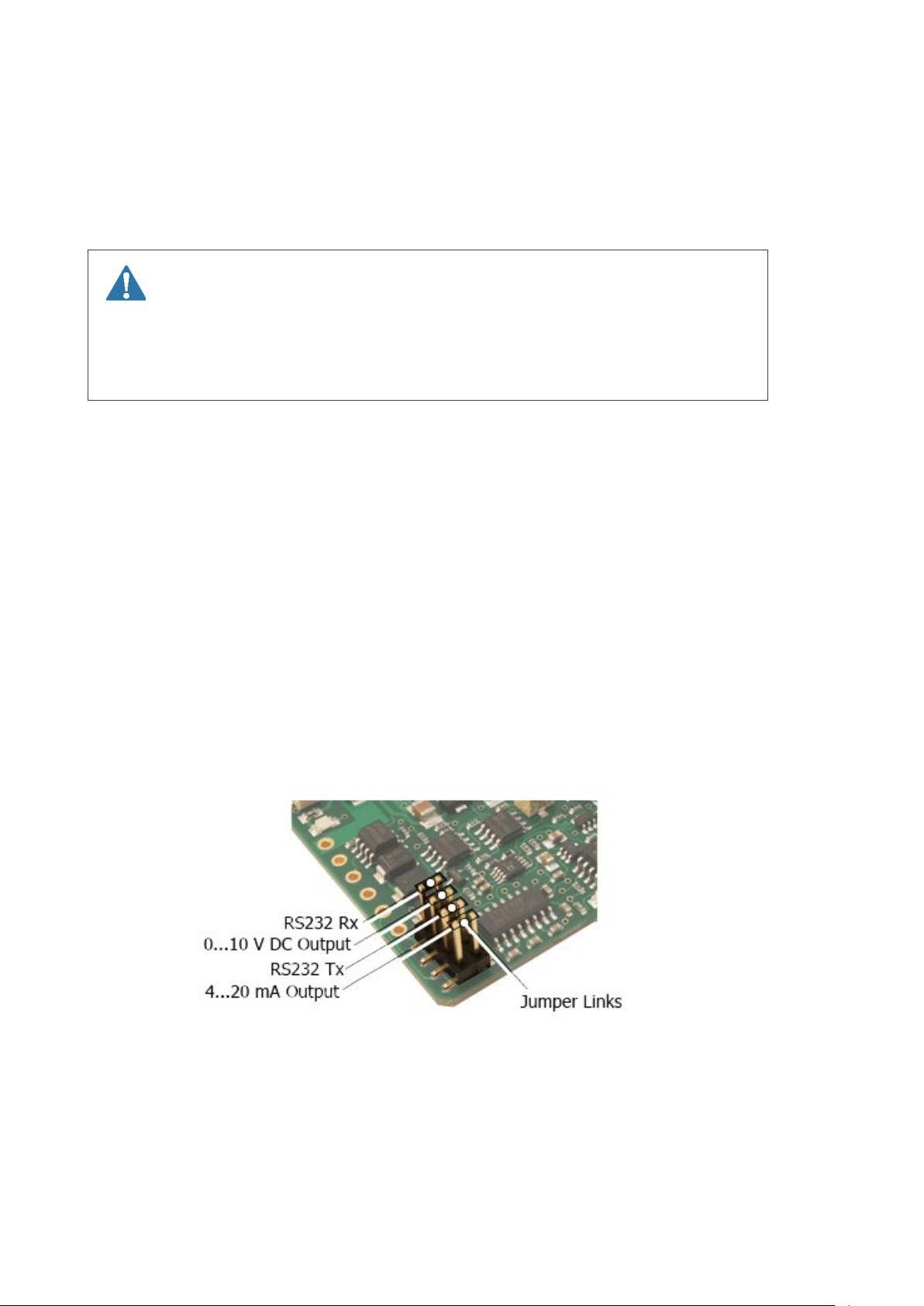
8.1 Setting the Output Type
The interface board is fitted with two jumper links which set the calibration type (Manual or
Automatic) and oxygen measurement range (100 % or 25 %).
These settings may be configured at any time by adjusting the position of the header pin jumper links
on the board.
WARNING: Danger of Death
The equipment MUST be powered OFF.
The jumper links must always be repositioned correctly and in the correct
orientation.
1. Using a suitable screwdriver, remove the four screws and lid from the transmitter housing.
2. Using thin-nosed pliers, remove and replace the jumper links to the desired positions:
• RS232; RS232 Rx and RS232 Tx
• Analogue output; 0…10 V DC and 4…20 mA
NOTE: When selecting the output, you must choose either 0…10 V DC and 4…20 mA or RS232 Tx
and RS232 Rx.
NOTE: Ensure jumper links are correctly seated and in the correct orientation, as shown in the output
jumper link configuration.
3. When the configuration is complete, replace the four screws and the lid: secure to the
transmitter housing using a suitable screwdriver.
Output Jumper Link Configuration
Page 18 of 34
Page 19
OXY-FLEX Series Oxygen Transmitter User Manual PST-UM-1400-EN-03
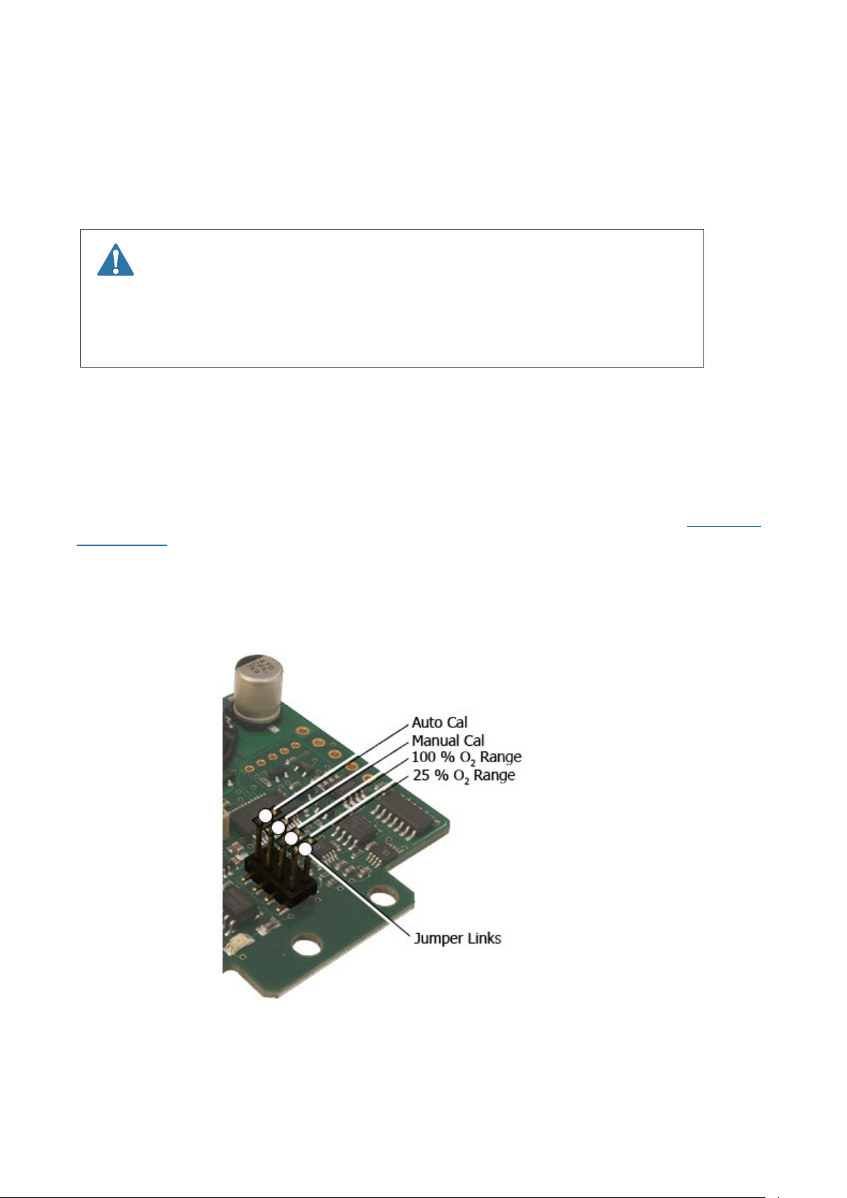
8.2 Setting the Calibration Type and Measurement Range
The interface board is fitted with two jumper links which set the calibration type (Manual or
Automatic) and oxygen measurement range (100 % or 25 %).
These settings may be configured at any time by adjusting the position of the header pin jumper links
on the board.
WARNING: Danger of Death
The equipment MUST be powered OFF.
The jumper links MUST always be repositioned correctly and in the correct
orientation.
1. Using a suitable screwdriver, remove the four screws and lid from the transmitter housing.
2. Using thin-nosed pliers, remove and replace the jumper links to the desired
positions:
• Calibration type; Manual (MANUAL CAL) or Automatic (AUTO CAL)
• Measuring range; 0.1…25 % O
or 0.1…100% O2
2
NOTE: Ensure jumper links are correctly seated and in the correct orientation as shown in Setting the
Output Type contained in this document.
3. When the configuration is complete, replace the four screws and the lid: secure to the
transmitter housing using a suitable screwdriver.
Calibration and Measurement Range
Page 19 of 34
Page 20

OXY-FLEX Series Oxygen Transmitter User Manual PST-UM-1400-EN-03
8.3 Digital Variant – RS232 Output
NOTE: When connecting the OXY-FLEX Series of transmitters using the RS232 connections, ensure
Tx
goes to Rx of the PC and Rx goes to Tx of the PC.
The OXY-FLEX Series of transmitters communicates via standard COM port settings that are default
settings on most PCs and many other RS232 compatible devices.
If, however, communication problems are occurring, use the settings below to configure the PC or
device COM Port:
• Baudrate: 9600
• Data bits: 8
• Parity: None
• Stop bits: 1
• Flow control: None
With the OXY-FLEX Series of transmitters RS232 outputs connected to a PC (or another RS232
compatible device), you can access two modes of operation: continuous data streaming and the menu
screens.
The menu structure was created using VT100 terminal codes; refer to Appendix A-Menu Structure
contained in this document for a full menu structure and example screens.
Recommended programs for communicating via PC serial RS232 are Tera Term, HyperTerminal
(Windows default), or PuTTY.
The following sub-sections are based on Tera Term usage and instructions may vary if using another
program.
>
When the OXY-FLEX Series of transmitters receives an <ENTER
or device, it automatically displays the Menu Password screen and stops streaming O2 % and Td
values.
When the correct password is entered, followed by the <ENTER
accessed.
The menu screens are primarily for diagnostics and information, although there are user-configurable
options that may be changed.
These are the automatic O2 calibration %, the amount of output filtering (averaging), and the analog
output ranges.
The menu security password may also be changed if required.
keystroke from the connected PC
>
keystroke, the menu screens are
Page 20 of 34
Page 21

OXY-FLEX Series Oxygen Transmitter User Manual PST-UM-1400-EN-03
8.4 Menu Security Password
The password is factory set to “default.” This, however, may be changed to a user-specific password.
1. Connect the OXY-FLEX Series of transmitters via the RS232 interface to the PC.
>
; the
2. Press <ENTER
3. Input your current security password.
4. Press <ENTER
5. Type “2” to access the
6. Type “3” to access the
7. Input your new security password.
NOTE: Password is case sensitive and has a maximum of 15 characters.
8. Press <ENTER
NOTE: The new password is now stored in memory and is retained on power loss.
<
NOTE: Pressing
ESC> returns the screen to the previous menu.
Menu Password
>
to access the
Configuration
Password Menu
>
to save.
Menu
screen displays.
screens.
menu.
screen.
8.5 Automatic Calibration Value
The system is factory set to automatically calibrate to 20.7 % O2 to allow simple calibration in the
fresh air.
The auto-calibration value is factory set to 20.7 % to take into account average humidity in the
atmosphere.
If a calibration with a gas of a different known O2 concentration is required, the factory set value may
be changed via the RS232 interface.
1. Connect the OXY-FLEX Series of transmitters via the RS232 interface to the PC.
>; the
2. Press <ENTER
3. Input your security password.
4. Press <ENTER> to access the
5. Type “2” to access the
6. Type “1” to access the
7. Input the oxygen concentration (%) of the calibration gas as a number to two decimal places.
8. Press <ENTER> to save.
NOTE: The new automatic calibration value is now stored in memory and is retained on power loss.
NOTE: If calibration is required with a different gas of known O
RS232 menus via a PC is not available, a manual calibration must be performed.
Refer to Manual Calibration contained in this document.
Menu Password
Menu
Configuration
Enter Auto Calib
screen displays.
screens.
menu.
screen.
concentration and access to the
2
8.6 Variable Output Filtering (Td Averaging)
The OXY-FLEX Series of transmitters are factory default to use adaptive output filtering to give an
optimum balance between output stability and response to oxygen changes.
This balance may be altered to suit the needs of your application.
1. Connect the OXY-FLEX Series of transmitters via the RS232 interface to the PC.
>
; the
2. Press <ENTER
Menu Password
screen displays.
Page 21 of 34
Page 22

OXY-FLEX Series Oxygen Transmitter User Manual PST-UM-1400-EN-03
3. Input your security password.
4. Press <ENTER> to access the
5. Type “2” to access the
6. Type “2” to access the
Configuration
Enter td Averaging
Menu screens
menu.
.
screen.
7. Input the required number, between 0 and 200; 0 for adaptive filtering (recommended),
1 for very fast and dynamic output response but relatively unstable to 200 for an extremely
stable output but very slow response to oxygen changes.
Press <ENTER> to save.
NOTE: The new averaging value is now stored in memory and is retained on power loss.
8.7 Analog Output Minimum and Maximum Ranges
The OXY-FLEX Series of transmitters are factory default to output a range of 0.1…25 % O2 via its two
analog outputs.
This range can be expanded to 0.1…100 % O2 by repositioning the jumper link as described in Setting
the Output Type contained in this document.
When the unit is reconfigured to output 0.1…100 % O2, the user also has the option to customize the
output ranges via RS232 fully. This is extremely useful in applications where the O2 variation is within
a narrow band as it allows the analog outputs to be tailored to this limited range.
NOTE: The minimum and maximum range adjustment does NOT apply to the RS232 output and is
overruled if the unit is reconfigured for 0.1…25 % O
Ensure the OXY-FLEX Series of transmitters are configured for 0.1…100 % O
operation.
2
operation; see System
2
Configuration contained in this document.
1. Connect the OXY-FLEX via the RS232 interface to the PC.
2. Press <
ENTER >; the
Menu Password
screen displays.
3. Input your security password.
Menu
4. Press <ENTER> to access the
5. Type “2” to access the
6. Type “3” to access the
Configuration
Enter O2 Max Range
screen.
menu.
screen.
7. Input the required number between 1.00 and 100.00 to represent the maximum output range.
NOTE: The number must also be greater than the saved minimum range.
8. Press <ENTER> to save.
>
9. Press <ESC
to return to the
10. Type “4” to access the
Enter O2 Min Range
Configuration
menu.
screen.
11. Input the required number between 0.00 and 99.00 to represent the minimum output range.
NOTE: The number must also be less than the saved maximum range.
12. Press <ENTER> to save.
NOTE: The new ranges are now stored in memory and are retained on power loss.
An example of changing the minimum and maximum output ranges would be in a fresh air atmosphere
where the O
range is between 20…21 %.
2
Page 22 of 34
Page 23

OXY-FLEX Series Oxygen Transmitter User Manual PST-UM-1400-EN-03
The user could set the minimum output range to 19 % and the maximum output range to 22 %, and the
outputs would vary linearly between.
The minimum and maximum ranges lock out the outputs at the set limits, so 19 % O
or lower would
2
set the analog outputs to 0 V DC / 4 mA, and 22 % O2 or higher would set the analog outputs to
10 V DC / 20 mA.
Page 23 of 34
Page 24
OXY-FLEX Series Oxygen Transmitter User Manual PST-UM-1400-EN-03
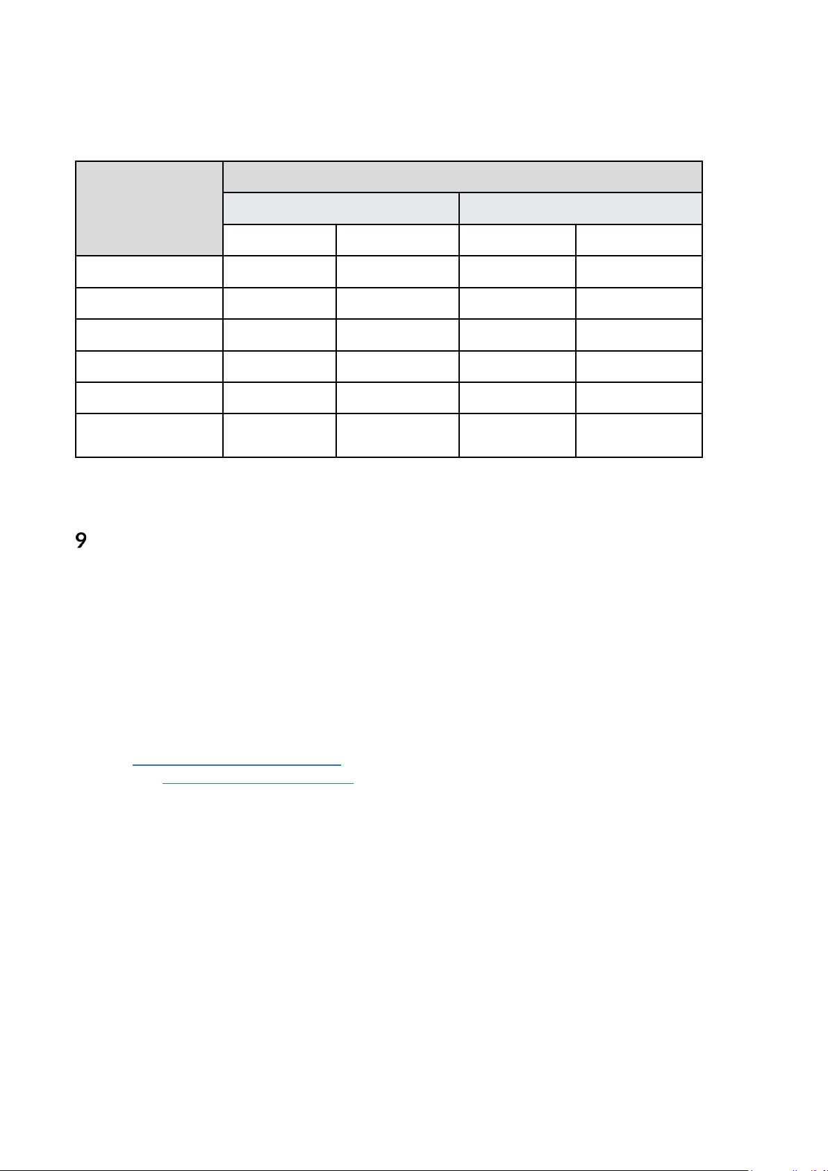
8.8 Analog Variants
Table 0…10 V DC and 4…0 mA Output Values
Output Values
O2 %
20.7 % 8.28 V DC 2.07 V DC 17.25 mA 7.34 mA
100 % - 10 V DC - 20 mA
90 % - 9.0 V DC - 18.4 mA
25 % 10 V DC 2.5 V DC 20 mA 8 mA
5 % 2.0 V DC 0.5 V DC 7.2 mA 4.8 mA
0.01%
(see Note)
NOTE: The analog output ranges represent 0.1…25% or 0.1…100% O2 however, as PST’s oxygen
sensors cannot measure below 0.1 % O2, this value is displayed as the range minimum.
0…10 V DC output 4…20 mA output
0.1 …25 % O2 0.1…100 % O2 0.1…25 % O2 0.1…100 % O2
0.04 V DC 0.01 V DC 4.06 mA 4.02 mA
Operation
9.1 Operating Tips
It is important that the attached oxygen sensor is installed and maintained correctly to ensure the best
performance from your equipment.
9.2 RS232 Operation
With the OXY-FLEX Series of transmitters RS232 outputs connected to a PC (or any other RS232
compatible device), you can access two modes of operation: continuous data streaming and the menu
screens.
Refer to Digital Variant – RS232 Output contained in this document.
Refer also to Appendix A- Menu Structure contained in this document.
9.3 Continuous Data Streaming
On power-up, after the initial 60s heater delay, the OXY-FLEX Series of transmitters will
automatically begin outputting the measured O
and raw value.
The averaged values give a stable output with the amount of averaging user variable, whilst the raw
un-averaged values allow the user to detect sudden oxygen changes.
The averaged value is the measurement output on both the 4…20 mA and 0 …10 V DC outputs.
The sensor
The O2 concentration (%) is the
t
value is the measure of the partial pressure of oxygen in the measurement gas.
d
t
value scaled by the stored calibration value.
d
concentration and sensor
2
t
as both are an averaged
d
Page 24 of 34
Page 25

OXY-FLEX Series Oxygen Transmitter User Manual PST-UM-1400-EN-03
To stop or restart the data streaming:
Connect the OXY-FLEX Series of transmitters via the RS232 interface to the PC.
Type “S” (not case sensitive).
NOTE: Data streaming automatically ceases during calibration.
9.4 Menu Screens
The menu screens are primarily for diagnostics and information, although there are user-configurable
options that may be changed.
Refer to Digital Variant – RS232 Output contained in this document.
To access the menu structure:
Connect the OXY-FLEX Series of transmitters via the RS232 interface to the PC.
Press < ENTER >; the
Menu Password
screen display
NOTE:
Input your security password.
Press <ENTER> to access the
The OXY-FLEX stops outputting O2% and
Menu
screens.
t
values.
d
Page 25 of 34
Page 26
OXY-FLEX Series Oxygen Transmitter User Manual PST-UM-1400-EN-03
Maintenance
WARNING: Danger of Explosion
Read the Safety Instructions before performing any type of maintenance on the
equipment.
The attached oxygen sensor is heated to over 700 oC /1300 oF and is a source of
ignition.
Ensure the sensor is cool before attempting to touch the equipment.
10.1 Calibrating
Our range of oxygen sensors do not directly measure the oxygen concentration but instead measures
the partial pressure of oxygen within the measurement gas.
In order to output an oxygen concentration (%), the sensor must be calibrated, or more specifically, rereferenced in a known gas concentration, typically fresh air.
Regular calibration removes the effects of application and atmospheric pressure changes and also
eliminates any sensor drift that may occur during the first few hundred hours of operation.
Calibration, or re-referencing, is achieved by connecting the calibration input to GND and monitoring
the status of the digital cycle output or by visually monitoring the onboard green LED.
During the calibration process, the output will either automatically calibrate to a fixed reference or
can be manually calibrated to any output by way of a PCB-mounted potentiometer.
NOTE: The fixed reference is factory set to 20.7 % O
value may be altered for calibration with a reference gas of any known oxygen concentration.
Any new calibration value will be stored on power loss.
The auto or manual calibrate function is user-configurable; refer to Setting the Calibration Type and
Measurement Range contained in this document.
Output Variant
0.1…25 % O2 20.7 % O2 / Fresh air
0.1…100 % O2 100 % O2 / Pure oxygen
Recommended Calibration Points /
Recommended Calibration Gas
for calibration in the fresh air; however, this
2
Page 26 of 34
Page 27

OXY-FLEX Series Oxygen Transmitter User Manual PST-UM-1400-EN-03
10.2 Automatic Calibration
Ensure the OXY-FLEX Series of transmitters are configured for automatic calibration.
Refer to Setting the Calibration Type and Measurement Range contained in this document.
Place the sensor probe in the calibration gas, typically fresh air.
2. Allow the output to stabilize for at least 5 minutes (10 minutes if powering from cold).
Referring to Electrical Connections contained in this document, apply GND to the CALIBRATE
input (pin 3) for a minimum of 12 seconds. During the 12 seconds, the CYCLE output (pin 4)
and the Green LED will go high/ON, blink rapidly, go high/ON, go low/OFF, then return to
cycling normally to indicate normal operation has resumed.
At this point, remove GND from pin 3.
∗
NOTE: The output will now track to the correct value for the calibration gas
3. Calibration is complete.
NOTE: New calibration values are stored in memory and retained on power loss.
10.3 Manual Calibration
Ensure the OXY-FLEX Series of transmitters are configured for manual calibration.
Refer to
Place the sensor probe in the calibration gas, typically fresh air.
Allow the output to stabilize for at least five minutes (10 minutes if powering from cold).
Referring to Electrical Connections contained in this document, apply GND to the CALIBRATE
input (pin 3) for a minimum of five seconds or until the CYCLE output and Green LED blink at a
steady 1 Hz. Remove GND from pin 3.
Manual Calibration is now initialized.
Referring to Setting the Calibration Type and Measurement Range contained in this document,
adjust the MANUAL CAL POT until the output equals the correct value of the calibration gas
concentration.
Re-apply GND to pin 3 for a minimum of five seconds. During the five seconds, the CYCLE
output/LED will blink rapidly, go high/on, go low/off, then return to cycling normally to indicate
normal operation has resumed. At this point, remove GND from pin 3.
NOTE: The output will now track to the correct value for the calibration gas ∗
Calibration is complete.
NOTE: New calibration values are stored in memory and retained on power loss.
Setting the Calibration Type and Measurement Range contained in this document.
* I
f calibrating in
with an error of ± 0.2 %. After calibration in
output should read 17.25 mA, and the RS232 will stream a five-character ASCII code representing the O
the
fresh air, the output value (RS232/Voltage/Current) given equates to 20.7 % oxygen
the
fresh air, the voltage output should read 8.28 V. The current
Page 27 of 34
2
%.
Page 28

OXY-FLEX Series Oxygen Transmitter User Manual PST-UM-1400-EN-03
10.4 Error Conditions
If the oxygen sensor is incorrectly connected or is damaged, the OXY-FLEX Series of transmitters will
highlight this by blinking the CYCLE output (pin 4) and Green LED in
pattern or continuously OFF.
In addition, an error code displays on the RS232 output, and the analog outputs will default to 4 mA
and 0 V.
If an error condition occurs, the equipment must be powered down and all wiring checked before reapplying the power.
If the error condition remains, contact [email protected] for guidance.
three short blinks – 1 long blink
10.5 Cleaning
Clean the outer surfaces of the housing regularly with non-abrasive materials to prevent a buildup of
contaminants.
Isopropyl alcohol (IPA) and a lint-free cloth are recommended.
CAUTION: Risk of damage!
Never use chemical cleaning agents or high-pressure water or steam to clean the
equipment.
10.6 Disposal
The OXY-FLEX Series of transmitters must be disposed of as electrical waste.
Please observe your local and national regulations.
Page 28 of 34
Page 29
OXY-FLEX Series Oxygen Transmitter User Manual PST-UM-1400-EN-03
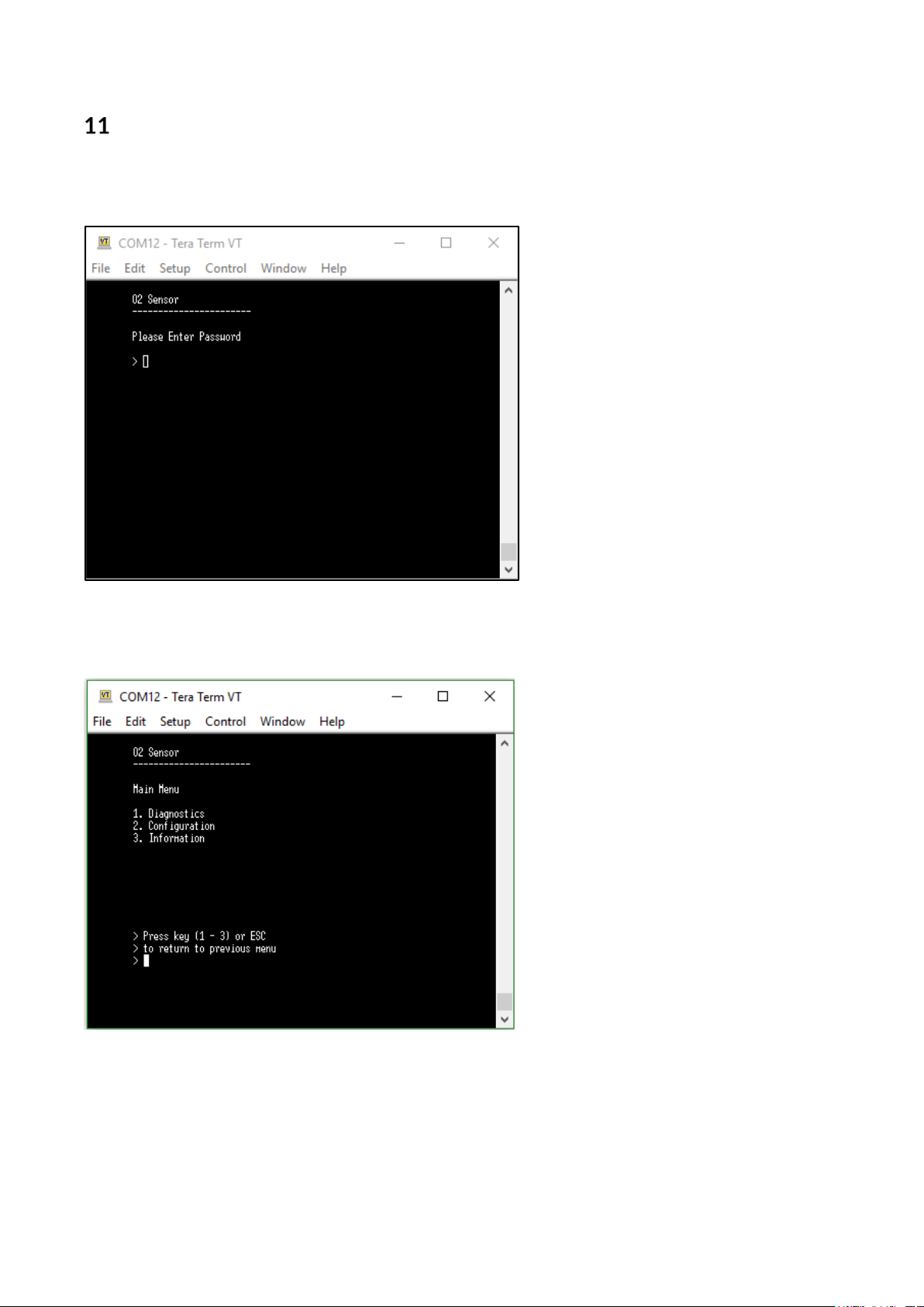
Appendix A – Menu Structure
Password Screen
Main Menu
Page 29 of 34
Page 30
OXY-FLEX Series Oxygen Transmitter User Manual PST-UM-1400-EN-03
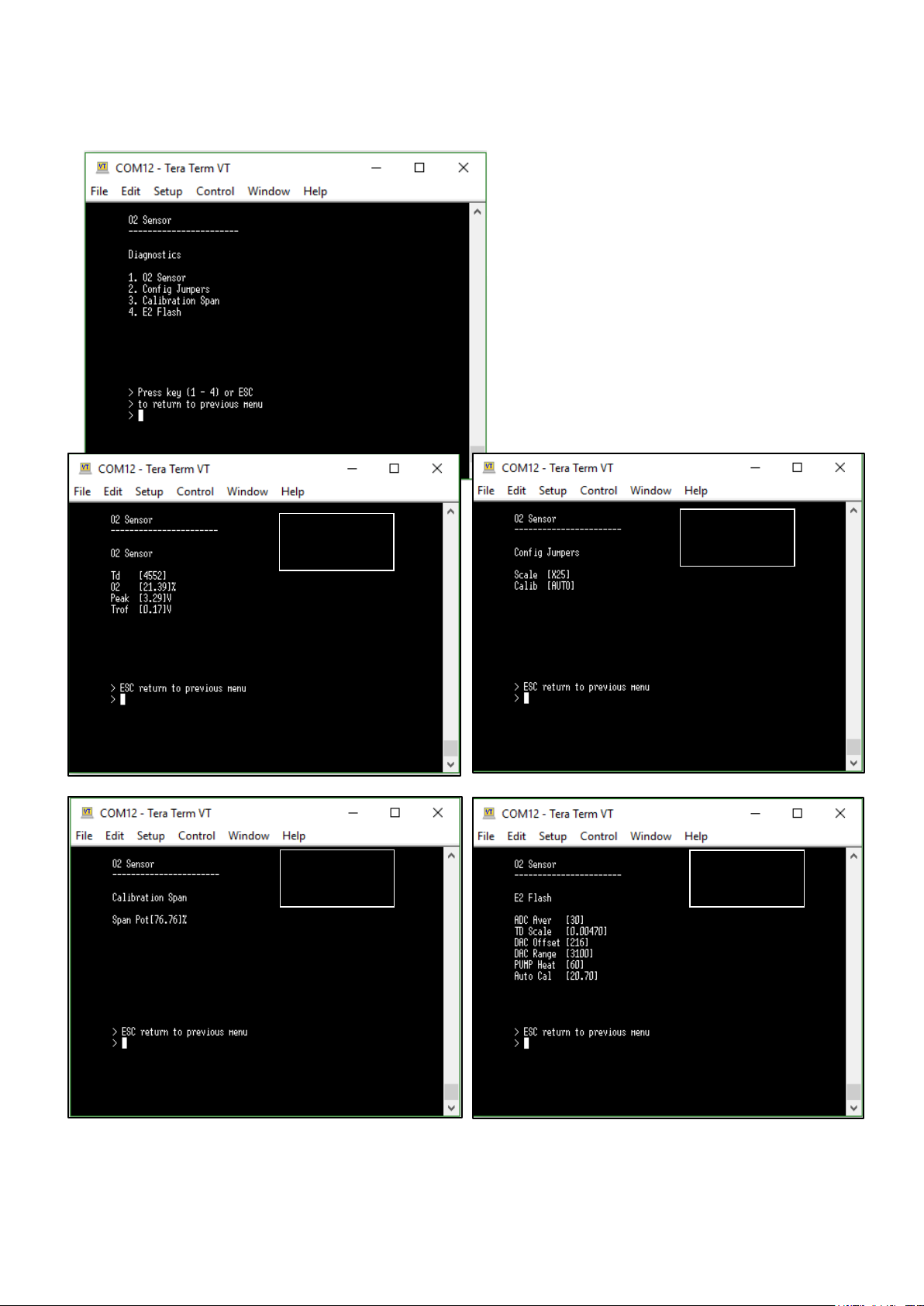
Diagnostics
Diagnostics Screens
Main Menu
Diagnostics
Menu 1.
Diagnostics
Menu 2.
Diagnostics
Menu 3.
Diagnostics
Menu 4.
Page 30 of 34
Page 31
OXY-FLEX Series Oxygen Transmitter User Manual PST-UM-1400-EN-03
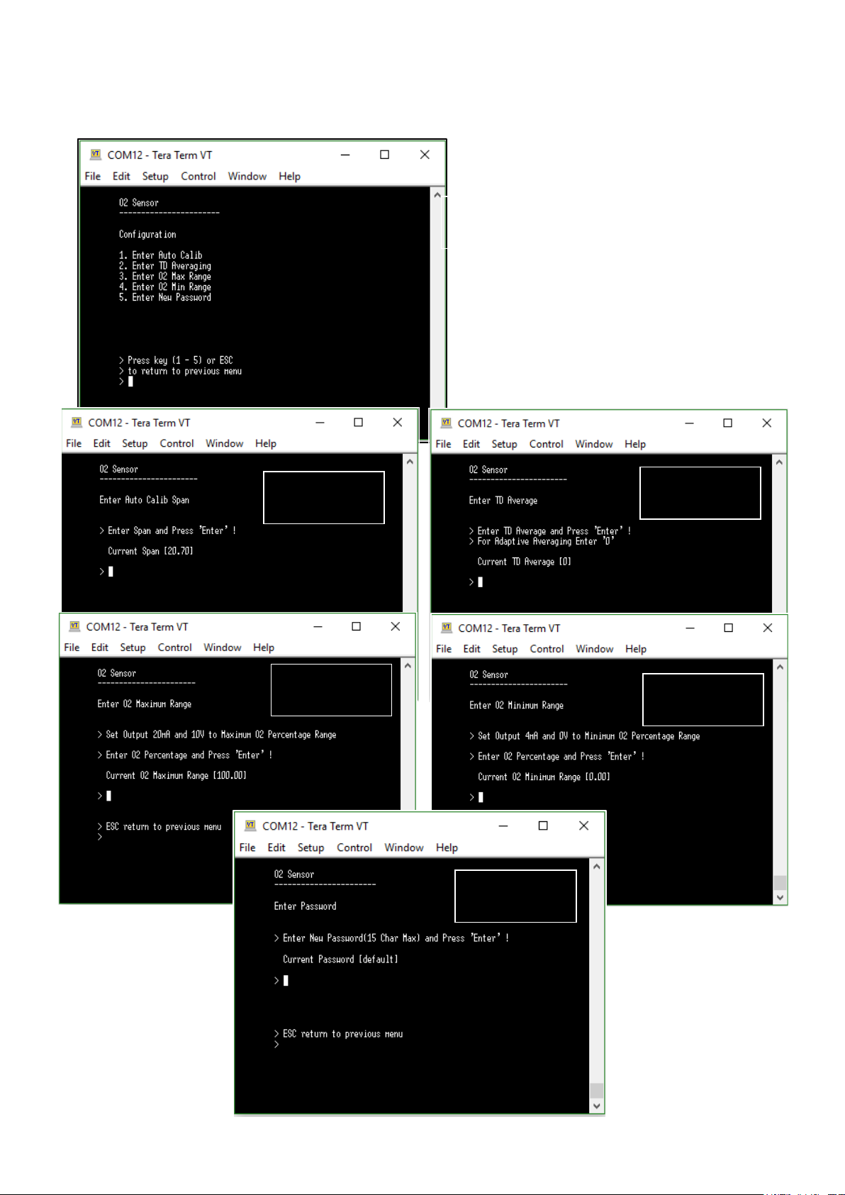
Configuration
Configuration Screens
Configuration
Main Menu
Configuration
Menu 1.
Configuration
Menu 3.
Configuration
Menu 2.
Menu 4.
Configuration
Menu 5.
Page 31 of 34
Page 32
OXY-FLEX Series Oxygen Transmitter User Manual PST-UM-1400-EN-03
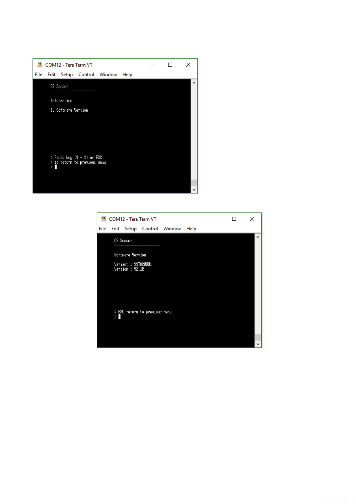
Information Screens
Page 32 of 34
Page 33

OXY-FLEX Series Oxygen Transmitter User Manual PST-UM-1400-EN-03
Appendix B – Quality, Recycling & Warranty Information
The PST Oxygen group of companies, Aii, Ntron, and SST comply with applicable national and
international standards and directives.
Full information can be found on our website at: O2 Compliance Documents (processsensing.com)
The compliance site contains information on the following directives:
• ATEX (Equipment for explosive atmospheres)
• REACH (Registration, Evaluation, Authorisation, and Restriction of Chemicals)
• RoHS (Restriction of hazardous substances in electrical and electronic equipment)
• ETL (The ETL Mark is proof of product compliance to North American safety standards)
• WEEE (Waste electrical and electronic equipment recycling)
• Recycling Policy
• Warranty & Returns
Page 33 of 34
Page 34

www.ProcessSensing.com
© 2022 Process Sensing Technologies
 Loading...