

Page 1
Page 2

Page 3

Table of Contents
Preface
About this User's Guide ....................................................................................................................... 5
What you will learn from this user's guide ......................................................................................................... 5
Conventions in this user's guide ......................................................................................................................... 5
Where to find more information ......................................................................................................................... 5
Hazardous voltages ............................................................................................................................................. 5
Hazardous locations ................................ ................................................................ ................................ ............ 5
Chapter 1
Introducing the OM-USB-2404-UI ........................................................................................................ 6
Functional block diagram ................................................................................................................................... 7
Chapter 2
Installing the OM-USB-2404-UI ............................................................................................................ 8
What comes with your shipment? ....................................................................................................................... 8
Hardware .......................................................................................................................................................................... 8
Software ............................................................................................................................................................................ 8
Documentation ................................ ................................................................ ................................................................ .. 8
Optional accessories ......................................................................................................................................................... 8
Unpacking........................................................................................................................................................... 8
Installing the software ........................................................................................................................................ 8
Installing the hardware ....................................................................................................................................... 8
Calibrating the OM-USB-2404-UI ..................................................................................................................... 9
Chapter 3
Functional Details ............................................................................................................................... 10
Components ...................................................................................................................................................... 10
Spring terminals ...............................................................................................................................................................10
Strain relief slot ................................................................................................................................................................11
USB connector .................................................................................................................................................................11
LED .................................................................................................................................................................................11
Connecting wires to the spring terminals ......................................................................................................... 11
TEDS sensor connections ................................................................................................................................................12
Signal source connections ................................................................................................................................................12
Timing options .................................................................................................................................................. 12
OM-USB-2404-UI circuitry ............................................................................................................................. 13
Analog input circuitry ......................................................................................................................................................13
Voltage and current modes ..............................................................................................................................................13
4-wire resistance and 4-wire RTD modes ........................................................................................................................13
3-wire RTD mode ............................................................................................................................................................14
2-wire resistance and quarter-bridge modes .....................................................................................................................14
Half-bridge and full-bridge modes ...................................................................................................................................14
Thermocouple mode ........................................................................................................................................................15
Excitation protection ........................................................................................................................................................15
Chapter 4
Specifications ...................................................................................................................................... 16
Analog input ..................................................................................................................................................... 16
Input mode ranges ............................................................................................................................................................17
Accuracy ..........................................................................................................................................................................17
Stability ............................................................................................................................................................................17
Input noise .......................................................................................................................................................................18
Excitation level ................................................................................................................................................................18
Power ................................................................................................................................................................ 18
Bus interface ..................................................................................................................................................... 19
3
Page 4

OM-USB-2404-UI User's Guide
Environmental .................................................................................................................................................. 19
Mechanical ....................................................................................................................................................... 19
Safety voltages .................................................................................................................................................. 19
Spring terminal connectors ............................................................................................................................... 19
Accessory products ........................................................................................................................................... 20
4
Page 5

Preface
About this User's Guide
What you will learn from this user's guide
This user's guide describes the Omega Engineering OM-USB-2404-UI data acquisition device and lists device
specifications.
Conventions in this user's guide
For more information
Text presented in a box signifies additional information and helpful hints related to the subject matter you are
reading.
Caution! Shaded caution statements present information to help you avoid injuring yourself and others,
damaging your hardware, or losing your data.
bold text Bold text is used for the names of objects on a screen, such as buttons, text boxes, and check boxes.
italic text Italic text is used for the names of manuals and help topic titles, and to emphasize a word or phrase.
Where to find more information
Additional information about OM-USB-2404-UI hardware is available on our website at www.omega.com. You
can also contact Omega Engineering by phone, fax, or email with specific questions.
Hazardous voltages
You can connect hazardous voltages to the OM-USB-2404-UI device's spring terminals. A hazardous voltage is
a voltage greater than 42.4 Vpk or 60 VDC to earth ground. Take the following precautions if you connect
hazardous voltages to the OM-USB-2404-UI:
Caution! Ensure that hazardous voltage wiring is performed only by qualified personnel adhering to local
electrical standards.
Do not mix hazardous voltage circuits and human-accessible circuits on the same device.
Make sure that devices and circuits connected to the OM-USB-2404-UI are properly insulated
from human contact.
When device terminals are hazardous voltage LIVE (>42.4Vpk/60 VDC), ensure that devices and
circuits connected to the OM-USB-2404-UI are properly insulated from human contact. A high
voltage screw terminal backshell (OM-ACC-176) must be installed when using hazardous
voltages to ensure that the terminals are not accessible.
Hazardous locations
The OM-USB-2404-UI is not certified for use in hazardous locations.
5
Page 6

Chapter 1
Introducing the OM-USB-2404-UI
The OM-USB-2404-UI is a USB 2.0 high-speed device that is supported under popular Microsoft® Windows®
operating systems. The OM-USB-2404-UI is fully compatible with both USB 1.1 and USB 2.0 ports.
The OM-USB-2404-UI provides four channels of 24-bit universal analog input with integrated signal
conditioning. The device can be used to measure several signals from sensors such as RTDs, thermocouples,
load cells, and other powered sensors. The four channels are individually configurable, so a different
measurement type can be performed on each channel. All channels are measured simultaneously at up to
100 S/s per channel.
The OM-USB-2404-UI can perform the following measurements:
Voltage
Current
Thermocouple
RTD (4-wire and 3-wire)
Resistance (4-wire and 2-wire)
Bridge-based sensors (quarter-, half-, and full-bridge)
Measurement ranges vary for each type of measurement.
The device features built-in current and voltage excitation. The excitation circuit is protected from overcurrent
and overvoltage fault conditions. Each channel also has a built-in thermistor for cold-junction compensation
(CJC) calculations when measuring thermocouples.
An analog pre-filter removes noise that may be present in the signals prior to conversion. With 250 VAC
channel-to-channel and channel-to-ground isolation, the OM-USB-2404-UI protects the individual channels and
connected computer from ground spikes, and ensures a reliable data stream. An on-board LED indicates the
status of the device.
Each channel has a detachable six-position spring terminal for field wiring connections. Additional connectors
are available for purchase. A strain relief kit is also available to secure signal wires.
The USB 2.0 high-speed driver transfers data at rates up to 480 Mbps. The OM-USB-2404-UI is powered by
the +5 volt USB supply from your computer. No external power is required.
6
Page 7
OM-USB-2404-UI User's Guide Introducing the OM-USB-2404-UI
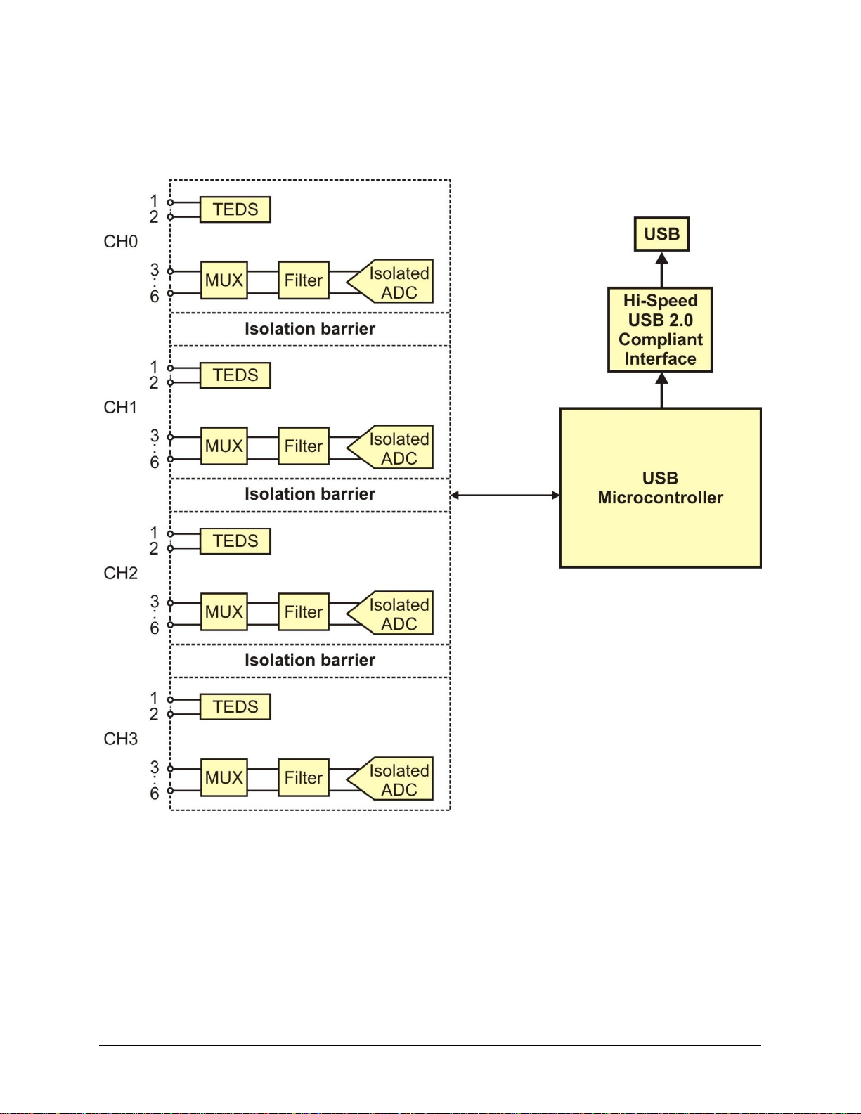
Functional block diagram
OM-USB-2404-UI functions are illustrated in the block diagram shown here.
Figure 1. OM-USB-2404-UI functional block diagram
7
Page 8

Chapter 2
Installing the OM-USB-2404-UI
What comes with your shipment?
Hardware
OM-USB-2404-UI
USB cable
Software
Software for OMB-DAQ-2400, OM-USB, OM-WEB, and OM-WLS Series Data Acquisition Modules CD
Documentation
In addition to this hardware user's guide, you should also receive the OMB-DAQ-2400, OM-USB, OM-WEB,
and OM-WLS Series Data Acquisition Software User's Guide. This booklet provides an overview of the
software you received with the device, and includes information about installing the software.
Optional accessories
OM-ACC-164 — Six-position screw terminal connector blocks (quantity four).
OM-ACC-176 — Backshell for use with the OM-ACC-164 six-position spring terminal connector blocks.
Provides strain relief and operator protection from high-voltage signals (quantity four).
Unpacking
As with any electronic device, take care while handling to avoid damage from static electricity. Before
removing the device from its packaging, ground yourself using a wrist strap or by simply touching the computer
chassis or other grounded object to eliminate any stored static charge.
If any components are missing or damaged, notify Omega Engineering immediately by phone, fax, or e-mail.
Installing the software
Refer to the Software for OMB-DAQ-2400, OM-USB, OM-WEB, and OM-WLS Series Data Acquisition
Modules User's Guide for instructions on installing the software. This booklet is available in PDF at
http://www.omega.com/manuals/manualpdf/M4803.pdf.
Installing the hardware
Install the software before you install your device
The driver needed to run the OM-USB-2404-UI is installed when you install the software. Therefore, you need
to install the software you plan to use before you install the hardware.
To connect a OM-USB-2404-UI device to your system, turn on your computer and connect the USB cable to an
available USB port on the computer or to an external USB hub connected to the computer. Connect the other
end of the USB cable to the USB connector on the device. No external power is required.
When you connect the device for the first time, a Found New Hardware dialog opens when the operating
system detects the device. The dialog closes after the device is installed.
The OM-USB-2404-UI LED blinks continuously to indicate that the device is initialized and receiving power.
8
Page 9
OM-USB-2404-UI User's Guide Installing the OM-USB-2404-UI
Allow the OM-USB-2404-UI to operate for at least 30 minutes before using the device. This warm up time is
required to achieve the specified rated accuracy of measurements.
USB 2.0 port or hub recommended
For optimum performance, connect the OM-USB-2404-UI to a USB 2.0 Hi-Speed host controller (480 Mbps)
and USB 2.0 high-speed hub. The OM-USB-2404-UI can be connected to a USB 1.1 Full-Speed port or hub,
although performance may be affected.
Caution! Do not disconnect any device from the USB bus while the computer is communicating with the
OM-USB-2404-UI, or you may lose data and/or your ability to communicate with the device.
If the LED is off
If the LED is on but then turns off, the computer has lost communication with the OM-USB-2404-UI device. To
restore communication, disconnect the USB cable from the computer and then reconnect it. This should restore
communication, and the LED should turn on.
Calibrating the OM-USB-2404-UI
The OM-USB-2404-UI is shipped fully calibrated. Calibration coefficients are stored in EEPROM. Return the
device to Omega Engineering when calibration is required. The normal calibration interval is once per year.
9
Page 10
Terminal
number
Signal
name
Signal description
1
T+
TEDS Data
2
T–
TEDS Common
3*
EX+/HI
Positive excitation or input signal
4
HI
Positive input signal
5*
EX–/LO
Negative excitation or input signal
6
LO
Negative input signal
Functional Details
Components
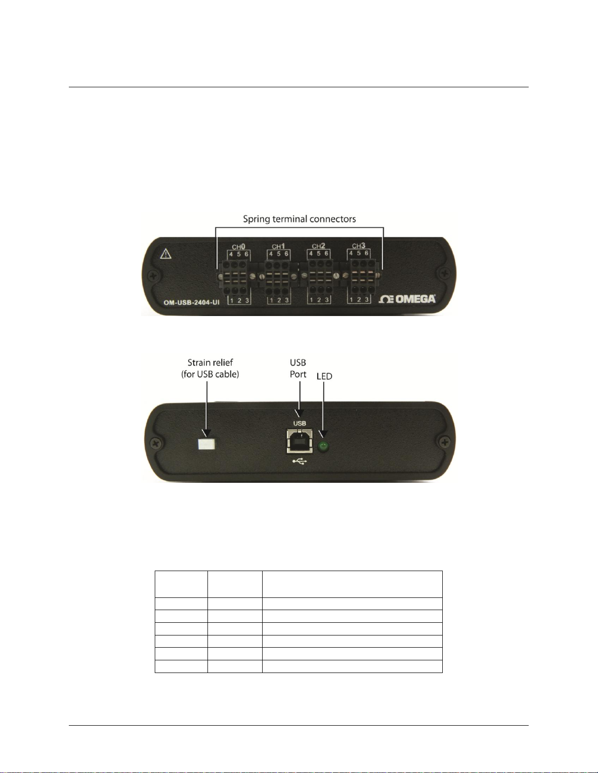
The OM-USB-2404-UI has the following external components:
Spring terminal connectors
Strain relief slot for USB cable
USB connector
LED
Figure 2. Front panel
Chapter 3
Spring terminals
The OM-USB-2404-UI has four 6-terminal connectors (CH0 to CH3) that provide connections for four analog
input channels. The signal names for the spring terminal in each connector are listed in the table below.
* Depending on the input mode, terminals 3 and 5 are either excitation signals or input signals.
Connect the positive signal of the signal source to the positive input signal terminal (HI).
Connect the negative signal of the signal source to the negative input signal terminal (LO).
Figure 3. Rear panel
6-terminal connector signal names
10
Page 11
OM-USB-2404-UI User's Guide Functional Details
Terminal
Voltage
TC
Current
Bridge
Resistance
RTD
Full
Half
Quarter
2-wire
4-wire
4-wire
3-wire
3 — HI
EX+
EX+
HI
EX+
EX+ 4 HI — HI
HI — HI — 5
LO
LO
EX–
EX–
LO
EX–
EX– 6 — — LO
LO — LO
LO
LED state
Device status
Off
The device is not connected to a USB port or hub.
Continuous single-blink
The device is operating normally.
Continuous double-blink
The device is operating normally. (Connected to a USB 1.1 port or hub.)
Connect to the excitation terminals (EX+/EX–)-if the sensor requires a separate excitation connection.
The spring terminal assignments for each input mode are listed in the following table.
6-position spring terminal assignments per input mode
Refer to "OM-USB-2404-UI circuitry" on page 13 for information about connections in each mode.
Strain relief slot
Use the strain relief slot to keep the USB cable from disconnecting from the device inadvertently. Feed a tie
wrap through the slot and secure to the USB cable when it is connected to the device.
USB connector
The USB connector provides +5 V power and communication. The voltage supplied through the USB connector
is system-dependent, and may be less than 5 V. No external power supply is required.
LED
The LED indicates the device status. When connected to a USB port, the LED blinks steadily to indicate that
the device is initialized and receiving power. The following table lists the possible LED states.
LED state/device status
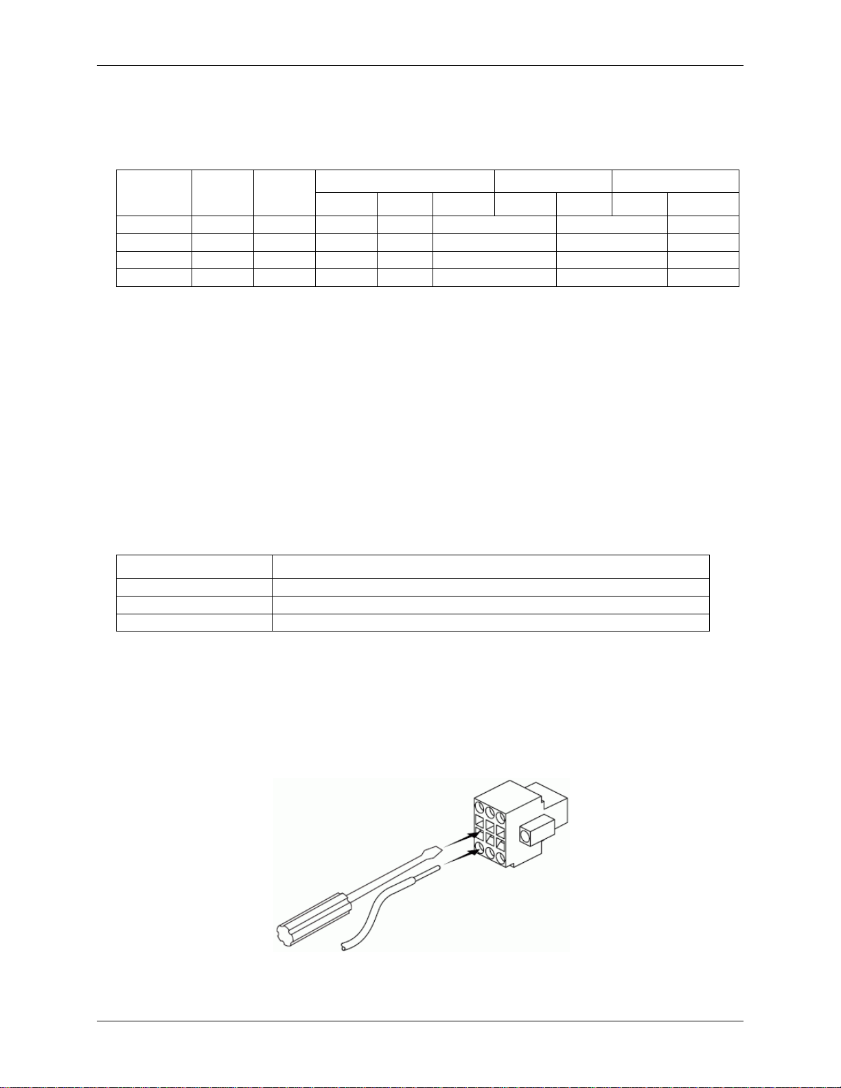
Connecting wires to the spring terminals
Use a flathead screwdriver with a blade smaller than 2.3 × 1.0 mm (0.09 × 0.04 in.) to connect wires to the
detachable spring terminal connectors. Use 18 to 28 AWG copper conductor wire with 7 mm (0.28 in.) of
insulation stripped from the end when wiring connections.
Insert the screwdriver into the spring clamp activation slot and press a wire into the corresponding connector
terminal, then remove the screwdriver to clamp the wire into the terminal.
Figure 4. Connecting a wire to the spring terminal connector
11
Page 12
OM-USB-2404-UI User's Guide Functional Details
TEDS sensor connections
The OM-USB-2404-UI supports class II TEDS "smart" sensors only. Connect the two TEDS lines to TEDS
Data (T+) and TEDS Common (T–), and ensure that neither T+ nor T– is tied in common to any of the signal
inputs (terminals 3 through 6).
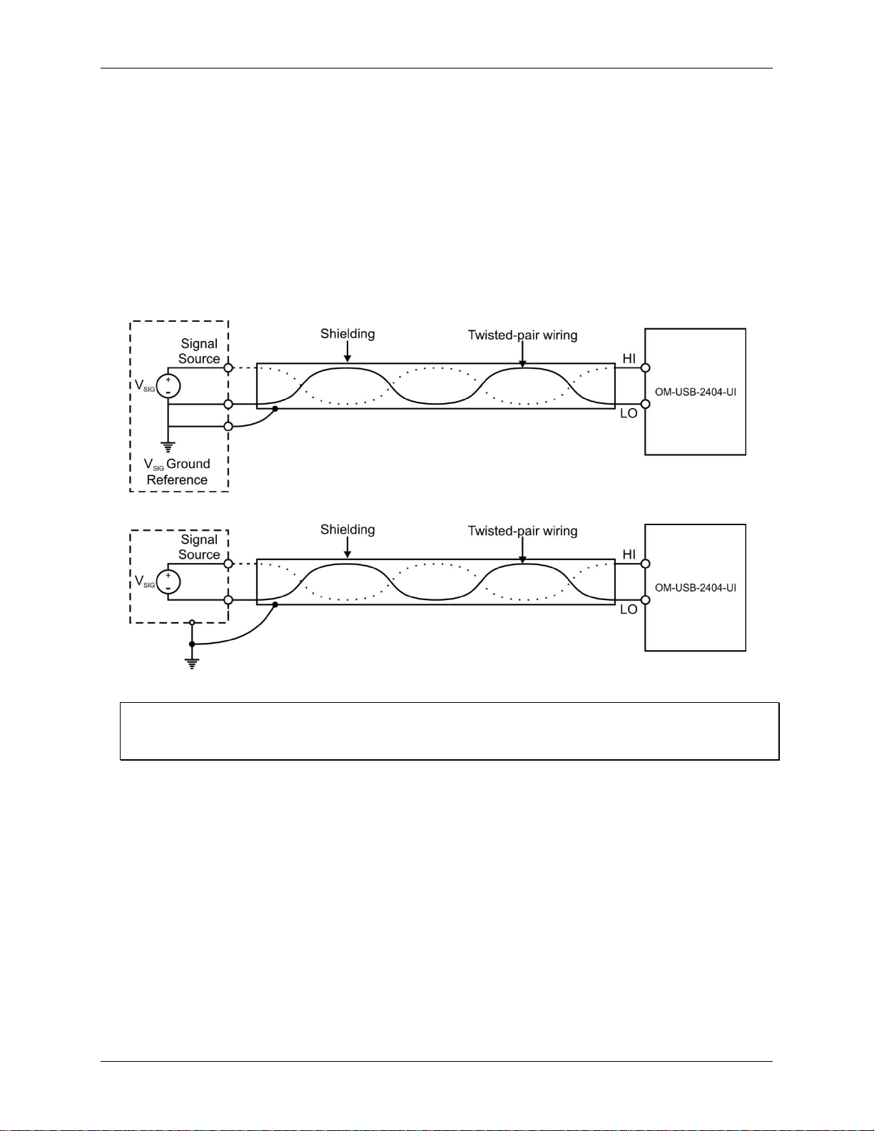
Signal source connections
You can connect ground-referenced or floating signal sources to the OM-USB-2404-UI. For optimum signal
quality, use shielded cables and twisted pair wiring whenever possible.
When making a floating connection between the signal source and the OM-USB-2404-UI, make sure the
voltages on the positive and negative connections are within the channel-to-earth voltage range. Refer to the
Specifications chapter for operating voltages and information about overvoltage protection.
Figure 5. Connecting a grounded signal source
Figure 6. Connecting a floating signal source
Don't connect to signals or use for measurements within category III or IV
Refer to the "Safety voltages" section in the Specifications chapter for information about Measurement
Categories.
Timing options
The OM-USB-2404-UI supports four timing options. Each option is optimized for different types of
applications by using different ADC conversion times.
High Speed: optimized for high-speed applications at the expense of noise rejection.
Best 60 Hz Rejection: optimized for rejection of 60 Hz noise.
Best 50 Hz Rejection: optimized for rejection of 50 Hz noise.
High Resolution: optimized for maximum overall noise rejection, and provides a good rejection of both
50 Hz and 60 Hz noise.
Refer to the analog input specifications for the conversion time and rejection ratio of each option.
12
Page 13
OM-USB-2404-UI User's Guide Functional Details
OM-USB-2404-UI circuitry
Analog input circuitry
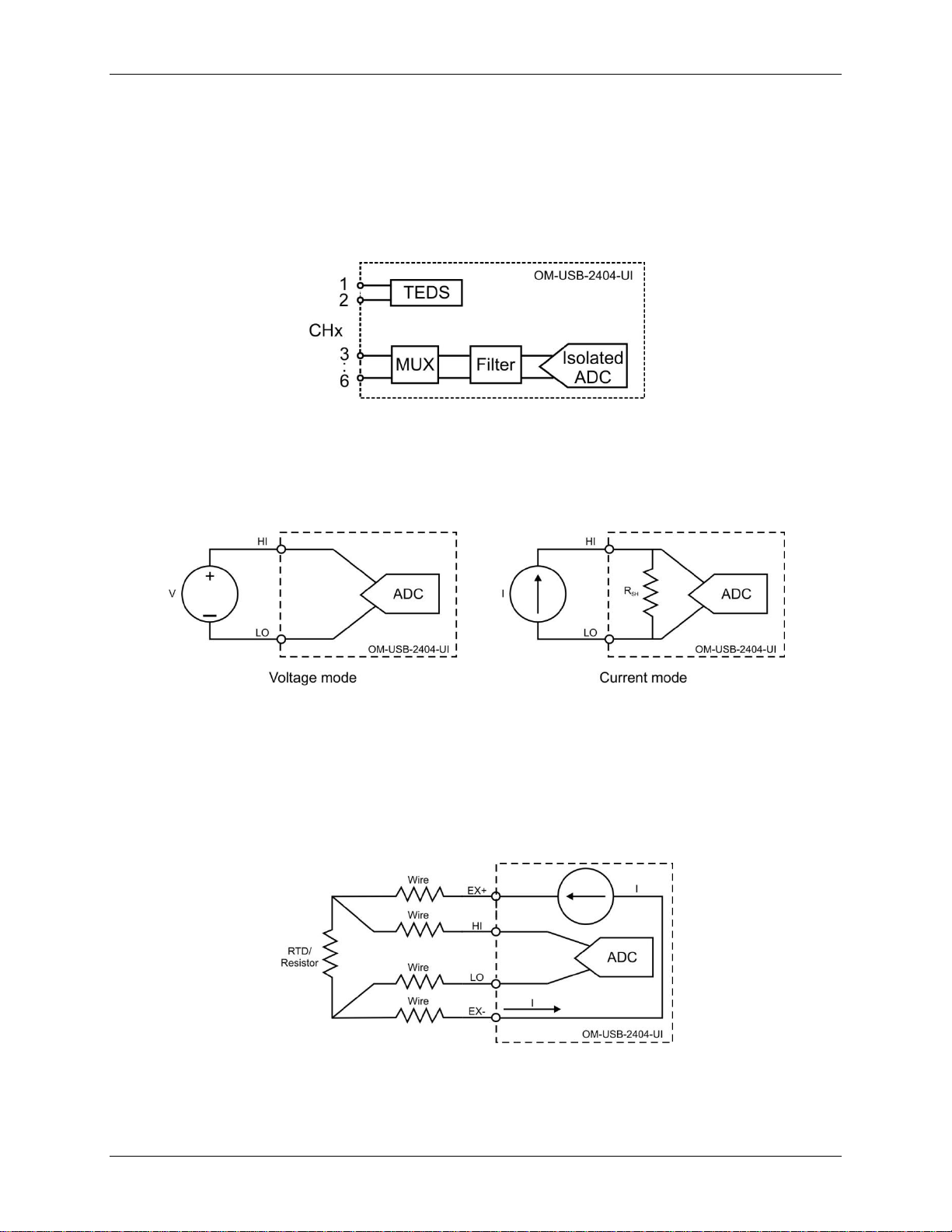
The OM-USB-2404-UI is channel-to-channel isolated. Four 24-bit analog-to-digital converters (ADCs)
simultaneously sample all four analog input channels. An excitation circuit is enabled for all input modes that
require excitation. The ADC and excitation circuits are reconfigured in each mode to accommodate each sensor
type. Figure 7 shows the input circuitry for one channel.
Figure 7. Input circuitry for one channel
Voltage and current modes
In voltage and current modes, connect the signal source to the OM-USB-2404-UI across the HI and LO
terminals. The current is computed from the voltage that the ADC measures across an internal shunt resistor.
Voltage and current mode connections are shown in Figure 8.
Figure 8. Voltage and current mode connections
4-wire resistance and 4-wire RTD modes
4-wire resistance and 4-wire RTD modes source a current which varies based on the resistance of the load
between the EX+ and EX– terminals. The measured resistance is calculated from the resulting voltage reading.
These modes are not affected by lead wire resistance, because a negligible amount of current flows across the
HI and LO terminals due to the high impedance of the ADC. 4-wire resistance and 4-wire RTD mode
connections are shown in Figure 9.
Figure 9. 4-wire resistance and 4-wire RTD mode connections
13
Page 14
OM-USB-2404-UI User's Guide Functional Details
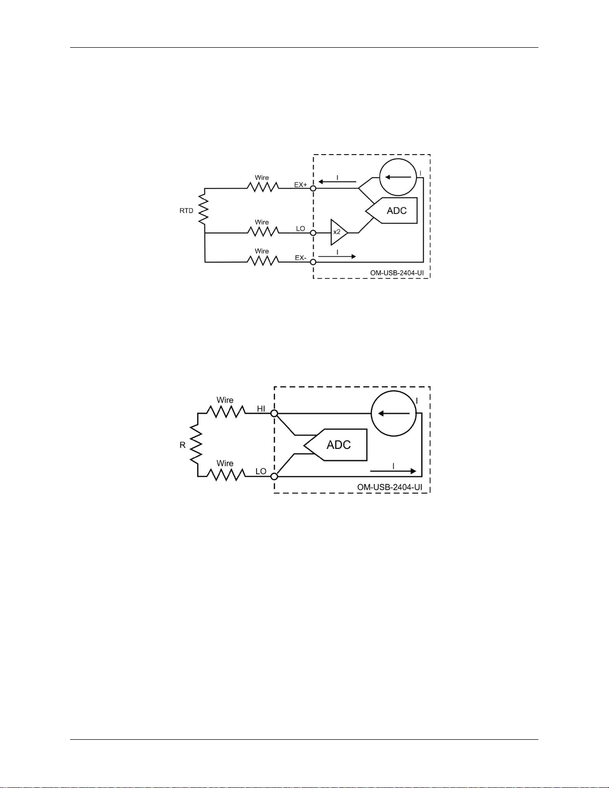
3-wire RTD mode
3-wire RTD mode sources a current which varies based on the resistance of the load between the EX+ and
EX– terminals. This mode compensates for lead wire resistance in hardware if all lead wires have the same
resistance. A gain of 2x is applied to the voltage across the negative lead wire. The ADC uses this voltage as the
negative reference to cancel the resistance error across the positive lead wire. 3-wire RTD mode connections are
shown in Figure 10.
Figure 10. 3-wire RTD mode connections
2-wire resistance and quarter-bridge modes
In 2-wire resistance and quarter-bridge modes, connect the two ends of the resistor or gauge to the OM-USB2404-UI across the HI and LO terminals. These modes source a current which varies based on the resistance of
the load between the HI and LO terminals. The resulting resistance is calculated from the voltage measurement.
2-wire and quarter-bridge modes do not compensate for lead wire resistance. 2-wire resistance and
quarter-bridge mode connections are shown in Figure 11.
Figure 11. 2-wire resistance and quarter-bridge mode connections
Half-bridge and full-bridge modes
Half-bridge and full-bridge modes use the internal voltage excitation to set the input range of the ADC, and
return voltage readings that are proportional to the excitation level. The internal excitation voltage is nominally
2.5 V, but it can vary based on the resistance of the sensor. Refer to the Specifications chapter for more
information about excitation levels.
In half-bridge mode, the HI input is referenced to EX–. In full-bridge mode, the ADC reads the HI and LO
inputs differentially.
14
Page 15
OM-USB-2404-UI User's Guide Functional Details
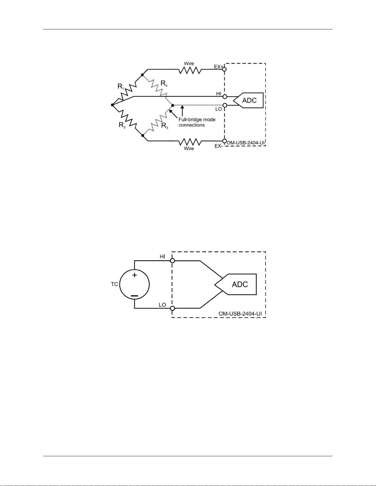
Half-bridge and full-bridge mode connections are shown in Figure 12. The dotted lines in the figure represent
the portion of the circuit that is only connected in full-bridge mode.
Figure 12. Half-bridge and full-bridge mode connections
Thermocouple mode
In thermocouple mode, connect the positive end of the thermocouple to HI, and the negative end of the
thermocouple to LO. This mode uses the ±1.25 mV range of the ADC to return a voltage reading. Use shielded
cables and twisted pair wiring, and ground the shielded cables.
Each channel has a built-in thermistor for cold-junction compensation (CJC) calculations. For improved CJC
sensor accuracy, operate the OM-USB-2404-UI in a stable temperature environment, and avoid placing heat
sources near the device or its connectors. Open thermocouple detection is not supported. Refer to the
Specifications chapter for more information about accuracy. Thermocouple mode connections are shown in
Figure 13.
Figure 13. Thermocouple mode connections
Excitation protection
The OM-USB-2404-UI excitation circuit is protected from overcurrent and overvoltage fault conditions. The
circuit is automatically disabled in the event of a fault condition. Whenever possible, channels automatically
recover after the fault is removed.
15
Page 16

Parameter
Conditions
Specification
Number of channels
4
A/D converter resolution
24-bit
A/D converter type
Delta-Sigma with analog pre-filtering
Sampling mode
Simultaneous
TEDS sensor type supported
IEEE 1451.4 TEDS Class II (interface)
Input mode
Voltage
Current
Resistance (4-wire and 2-wire)
RTD (3-wire and 4-wire)
Thermocouple
Quarter-bridge
Half-bridge
Full-bridge
Conversion time
(No channels in TC mode)
High speed
10 ms for all channels
Best 60 Hz rejection
110 ms for all channels
Best 50 Hz rejection
130 ms for all channels
High resolution
500 ms for all channels
Conversion time
(One or more channels in TC mode)
High speed
20 ms for all channels
Best 60 Hz rejection
120 ms for all channels
Best 50 Hz rejection
140 ms for all channels
High resolution
510 ms for all channels
Overvoltage protection
Terminals 1 and 2
±30 V
Terminals 3 through 6, across any
combination
±60 V
Input impedance
Voltage mode
(±60 V, ±15 V, ±4 V)
1 MΩ
Current mode
<40 Ω
All other modes
1 GΩ
Input bias current
<1 nA
Integral non-linearity (INL)
±15 ppm
Common mode rejection ratio
(CMRR)
100 dB
Normal mode rejection ratio
(NMRR)
Best 60 Hz rejection
90 dB at 60 Hz
Best 50 Hz rejection
80 dB at 50 Hz
High resolution
65 dB at 50 Hz and 60 Hz
Specifications
All specifications are subject to change without notice.
Typical for the range 0 to 60 °C unless otherwise noted.
Analog input
Table 1. Analog input specifications
Chapter 4
16
Page 17
OM-USB-2404-UI User's Guide Specifications
Input mode
Nominal range(s)
Actual range(s)
Voltage
±60 V, ±15 V, ±4 V, ±1 V, ±125 mV
±60 V, ±15 V, ±4 V, ±1 V, ±125 mV
Current
±25 mA
±25 mA
4-wire and 2-wire resistance
10 kΩ, 1 kΩ
10.5 kΩ, 1.05 kΩ
Thermocouple
±125 mV
±125 mV
4-wire and 3-wire RTD
Pt 1000, Pt 100
5.05 kΩ, 505 Ω
Quarter-bridge
350 Ω, 120 Ω
390 Ω, 150 Ω
Half-bridge
±500 mV/V
±500 mV/V
Full-bridge
±62.5 mV/V, ±7.8 mV/V
±62.5 mV/V, ±7.8125 mV/V
Mode, range
Gain error (percent of reading)
Offset error (ppm of range)
Typical 25 ºC, ±5 ºC, –40 to 70 ºC maximum
Voltage, ±60 V
±0.3, ±0.4
±20, ±50
Voltage, ±15 V
±0.3, ±0.4
±60, ±180
Voltage, ±4 V
±0.3, ±0.4
±240, ±720
Voltage, ±1 V
±0.1, ±0.18
±15, ±45
Voltage/Thermocouple, ±125 mV
±0.1, ±0.18
±120, ±360
Current, ±25 mA
±0.1, ±0.6
±30, ±100
4-wire and 2-wire (note 1) resistance,
10 kΩ
±0.1, ±0.5
±120, ±320
4-wire and 2-wire (note 1) resistance,
1 kΩ
±0.1, ±0.5
±1200, ±3200
4-wire and 3-wire RTD, Pt 1000
±0.1, ±0.5
±240, ±640
4-wire and 3-wire RTD, Pt 100
±0.1, ±0.5
±2400, ±6400
Quarter-bridge, 350 Ω
±0.1, ±0.5
±2400, ±6400
Quarter-bridge, 120 Ω
±0.1, ±0.5
±2400, ±6400
Half-bridge, ±500 mV/V
±0.03, ±0.07
±300, ±450
Full-bridge, ±62.5 mV/V
±0.03, ±0.08
±300, ±1000
Full-bridge, ±7.8 mV/V
±0.03, ±0.08
±2200, ±8000
Cold-junction compensation sensor
accuracy
±1 ºC, typical
Measurement conditions
Gain drift (ppm of reading/ ºC)
Offset drift (ppm of range/ ºC)
Voltage, ±60 V
±20
±0.2
Voltage, ±15 V
±20
±0.8
Voltage, ±4 V
±20
±3.2
Voltage, ±1 V
±10
±0.2
Voltage/thermocouple, ±125 mV
±10
±1.6
Current, ±25 mA
±15
±0.4
4-wire and 2-wire resistance, 10 kΩ
±15
±3
4-wire and 2-wire resistance, 1 kΩ
±15
±30
Input mode ranges
Table 2. Input mode range specifications
Accuracy
Table 3. Accuracy specifications
Note 1: 2-wire resistance mode accuracy depends on the lead wire resistance. This table assumes 0 Ω of lead
wire resistance.
Stability
Table 4. Stability specifications
17
Page 18
OM-USB-2404-UI User's Guide Specifications
4-wire and 3-wire RTD, Pt 1000
±15
±6
4-wire and 3-wire RTD, Pt 100
±15
±60
Quarter-bridge, 350 Ω
±15
±120
Quarter-bridge, 120 Ω
±15
±240
Half-bridge, ±500 mV/V
±3
±20
Full-bridge, ±62.5 mV/V
±3
±20
Full-bridge, ±7.8 mV/V
±3
±20
Mode, range
Conversion time
High speed
Best of 60 Hz
rejection
Best of 50 Hz
rejection
High resolution
Voltage, ±60 V
7.6
1.3
1.3
0.5
Voltage, ±15 V
10.8
1.9
1.9
0.7
Voltage, ±4 V
10.8
2.7
2.7
1.3
Voltage, ±1 V
7.6
1.3
1.3
0.5
Voltage/Thermocouple, ±125 mV
10.8
1.9
1.9
1.0
Current, ±25 mA
10.8
1.9
1.9
1.0
4-wire and 2-wire resistance, 10 kΩ
4.1
1.3
0.8
0.3
4-wire and 2-wire resistance, 1 kΩ
7.1
1.8
1.2
0.7
4-wire and 3-wire RTD, Pt 1000
7.6
1.7
1.1
0.4
4-wire and 3-wire RTD, Pt 100
10.8
1.9
1.9
0.9
Quarter-bridge, 350 Ω
5.4
1.0
1.0
0.7
Quarter-bridge, 120 Ω
5.4
1.0
1.0
0.7
Half-bridge, ±500 mV/V
3.8
0.5
0.5
0.2
Full-bridge, ±62.5 mV/V
5.4
1.0
1.0
0.8
Full-bridge, ±7.8 mV/V
30
4.7
4.7
2.3
Measurement conditions
Load resistance (Ω)
Excitation (V)
Half-bridge
700
2.5
Half-bridge
240
2.0
Full-bridge
350
2.7
Full-bridge
120
2.2
Load resistance (Ω)
Excitation (mV)
120
50
350
150
1,000
430
10,000
2,200
Parameter
Specification
Current consumption from USB
500 mA, maximum
Input noise
Excitation level
Table 6. Half-bridge and full-bridge mode excitation level specifications
Table 5. Input noise (ppm of range
) specifications
rms
Power
Table 7. Resistance, RTD, and quarter-bridge mode excitation level specifications
Table 8. Power specifications
18
Page 19
OM-USB-2404-UI User's Guide Specifications
Parameter
Specification
USB specification
USB 2.0 Hi-Speed
Parameter
Specification
Operating temperature range
0 to 60 ºC
Storage temperature range
–40 to 85 ºC
Operating humidity
10 to 90% RH, non-condensing
Storage humidity
5 to 95% RH, non-condensing
Maximum altitude
2000 meter (6562 feet)
Parameter
Specification
Dimensions
5.27" (L) x 5.64" (W) x 1.54" (H) (134 mm x 143 mm x 39 mm)
Weight
1.25 lbs (567 grams)
Parameter
Conditions
Specification
Channel-to-earth ground isolation
Continuous
250 VAC, Measurement Category II (Note 3)
Withstand
2300 VAC, verified by a 5 second dielectric withstand test
Channel-to-channel isolation
Continuous
250 VAC, Measurement Category II (Note 3)
Withstand
1390 VAC, verified by a 5 second dielectric withstand test
Connector type
Four 6-position spring terminal connectors
Spring terminal wiring
18 to 28 AWG copper conductor wire with 7 mm (0.28 in.) of insulation stripped from the
end.
Bus interface
Table 9. Bus interface specifications
Environmental
Table 10. Environmental specifications
Note 2: The OM-USB-2404-UI is intended for indoor use only, but may be used outdoors if installed in a
suitable enclosure
Mechanical
Table 11. Mechanical specifications
Safety voltages
Connect only voltages that are within the limits specified in this table.
Table 12. Safety specifications
Note 3: Measurement Category II is for measurements performed on circuits directly connected to the
electrical distribution system. This category refers to local-level electrical distribution, such as that
provided by a standard wall outlet, for example 115 V for US or 230 V for Europe.
Caution! Do not connect the device to signals or use for measurements within Measurement Categories
III or IV.
Spring terminal connectors
Table 13. Spring terminal specifications
19
Page 20
OM-USB-2404-UI User's Guide Specifications
Terminal number
Signal name
Signal description
1
T+
TEDS Data
2
T–
TEDS Common
3
EX+/HI (Note 4)
Positive excitation or input signal
4
HI
Positive input signal
5
EX–/LO (Note 4)
Negative excitation or input signal
6
LO
Negative input signal
Input mode
Signal terminals
1 2 3 4 5
6
Voltage
T+
T– — HI
LO — Current
T+
T–
HI — LO — 4-wire resistance
T+
T–
EX+
HI
EX–
LO
2-wire resistance
T+
T–
HI — LO
—
Thermocouple
T+
T– — HI
LO — 4-wire RTD
T+
T–
EX+
HI
EX–
LO
3-wire RTD
T+
T–
EX+ — EX–
LO
Quarter-bridge
T+
T–
HI — LO — Half-bridge
T+
T–
EX+
HI
EX– — Full-bridge
T+
T–
EX+
HI
EX–
LO
ACC-164
6-position spring terminal connector block (quantity four)
ACC-176
Backshell for use with the ACC-164 6-position spring terminal connector blocks. Provides
strain relief and operator protection from high-voltage signals (quantity four).
Table 14. Signal names
Note 4: Depending on the input mode, terminals 3 and 5 are either excitation signals or input signals.
Table 15. Terminal assignments per input mode
Accessory products
Table 16. Accessory products
20
Page 21

Page 22

 Loading...