

Page 1
Page 2
Page 3

Table of Contents
Preface
About this User's Guide ....................................................................................................................... 5
What you will learn from this user's guide ......................................................................................................... 5
Conventions in this user’s guide ......................................................................................................................... 5
Where to find more information ......................................................................................................................... 5
Chapter 1
Introducing the OM-USB-1408FS ........................................................................................................ 6
OM-USB-1408FS block diagram ....................................................................................................................... 7
Software features ................................................................................................................................................ 7
Connecting a OM-USB-1408FS to your computer is easy ................................................................................. 8
Chapter 2
Installing the OM-USB-1408FS ............................................................................................................ 9
What comes with your OM-USB-1408FS shipment?......................................................................................... 9
Hardware .......................................................................................................................................................................... 9
Additional documentation ................................................................................................ ................................................. 9
Unpacking the OM-USB-1408FS ....................................................................................................................... 9
Installing the software ...................................................................................................................................... 10
Installing the hardware ..................................................................................................................................... 10
Calibrating the OM-USB-1408FS .................................................................................................................... 10
Chapter 3
Functional Details ............................................................................................................................... 11
Theory of operation - analog input acquisition modes ..................................................................................... 11
Software paced mode .......................................................................................................................................................11
Continuous scan mode .....................................................................................................................................................11
External components ........................................................................................................................................ 11
USB connector .................................................................................................................................................................12
LED .................................................................................................................................................................................12
Screw terminal wiring ......................................................................................................................................................12
Main connector and pin out .............................................................................................................................................13
Analog input terminals (CH0 IN - CH7 IN).....................................................................................................................13
Analog output terminals (D/A OUT 0 and D/A OUT 1) ..................................................................................................16
Digital I/O terminals (Port A0 to A7, and Port B0 to B7) ................................................................................................16
Power terminals ...............................................................................................................................................................16
External trigger terminal ..................................................................................................................................................17
Counter terminal ..............................................................................................................................................................17
+2.5VREF terminal ..........................................................................................................................................................17
SYNC terminal ................................................................................................................................................................17
Ground terminals .............................................................................................................................................................17
Accuracy ........................................................................................................................................................... 17
OM-USB-1408FS channel gain queue feature ................................................................................................. 20
Synchronizing multiple units ............................................................................................................................ 21
Chapter 4
Specifications ...................................................................................................................................... 22
Analog input ..................................................................................................................................................... 22
Analog output ................................................................................................................................................... 24
Digital input/output........................................................................................................................................... 24
External trigger ................................................................................................................................................. 25
External clock input/output............................................................................................................................... 25
Counter section ................................................................................................................................................. 25
3
Page 4

OM-USB-1408FS User's Guide
Non-volatile memory ........................................................................................................................................ 26
Microcontroller ................................................................................................................................................. 26
Power ................................................................................................................................ ................................ 26
General ............................................................................................................................................................. 26
Environmental .................................................................................................................................................. 27
Mechanical ....................................................................................................................................................... 27
Main connector and pin out .............................................................................................................................. 27
4-channel differential mode .............................................................................................................................................27
8-channel single-ended mode ...........................................................................................................................................28
4
Page 5
Preface
About this User's Guide
What you will learn from this user's guide
This user’s guide explains how to install, configure, and use the OM-USB-1408FS so that you get the most out
of its USB data acquisition features.
This user’s guide also refers you to related documents available on our web site, and to technical support
resources.
Conventions in this user’s guide
For more information on …
Text presented in a box signifies additional information and helpful hints related to the subject matter you are
reading.
Caution! Shaded caution statements present information to help you avoid injuring yourself and others,
damaging your hardware, or losing your data.
< : > Angle brackets that enclose numbers separated by a colon signify a range of numbers, such as those assigned
to registers, bit settings, etc.
bold text Bold text is used for the names of objects on the screen, such as buttons, text boxes, and check boxes. For
example:
1. Insert the disk or CD and click the OK button.
italic text Italic text is used for the names of manuals and help topic titles, and to emphasize a word or phrase. For
example:
Never touch the exposed pins or circuit connections on the board.
Where to find more information
For additional information relevant to the operation of your hardware, refer to the Documents subdirectory
where you installed the software, or search for your device on our website at www.omega.com.
5
Page 6
Chapter 1
Introducing the OM-USB-1408FS
This user's guide contains all of the information you need to connect the OM-USB-1408FS to your computer
and to the signals you want to measure.
The OM-USB-1408FS is a USB 2.0 full-speed, device that is supported under popular Microsoft® Windows®
operating systems. The OM-USB-1408FS is fully compatible with both USB 1.1 and USB 2.0 ports.
The OM-USB-1408FS features eight analog inputs, two 12-bit analog outputs, 16 digital I/O connections, and
one 32-bit external event counter.
The analog inputs are software configurable for either eight 13-bit single-ended inputs or four 14-bit differential
inputs. The 16 digital I/O lines are independently selectable as input or output in two 8-bit ports. The 32-bit
counter can count TTL pulses. A SYNC (synchronization) input/output line allows you to pace the analog input
acquisition of one USB module from the clock output of another.
The OM-USB-1408FS is powered by the +5 volt USB supply from your computer. No external power is
required.
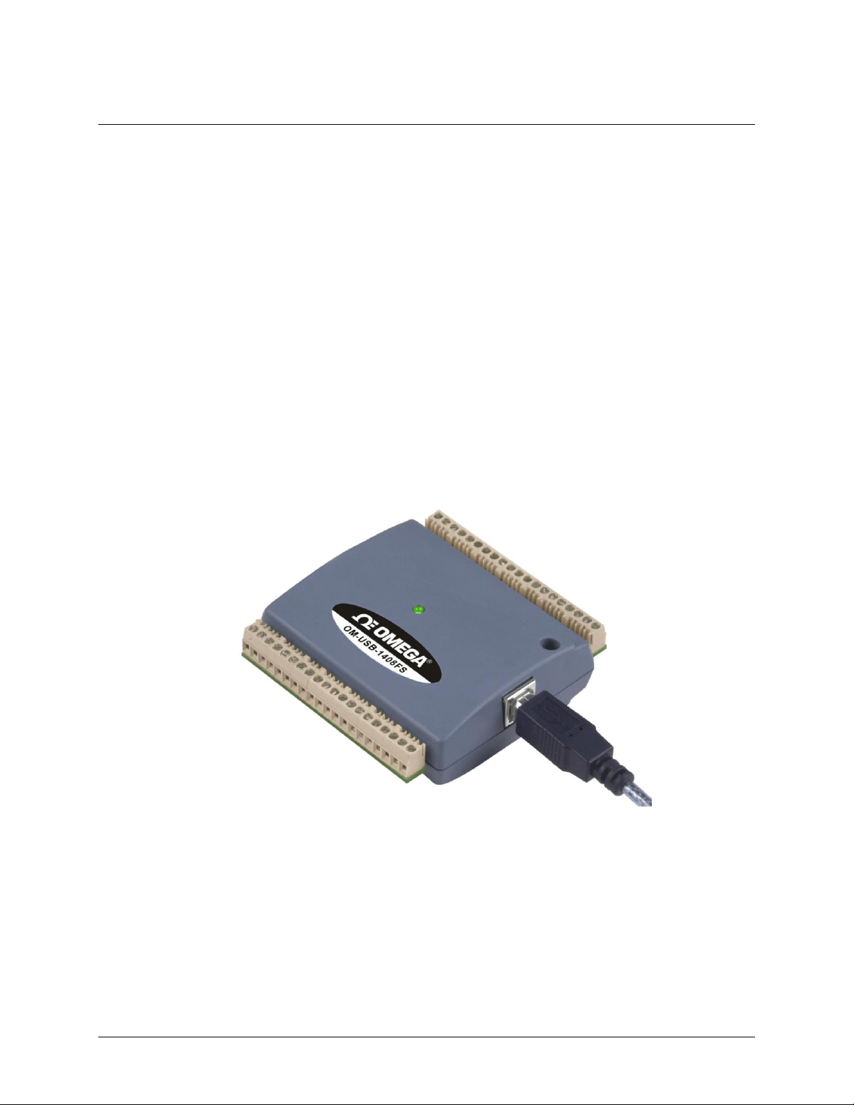
The OM-USB-1408FS is shown in Figure 1. I/O connections are made to the screw terminals located along
each side of the OM-USB-1408FS.
Figure 1. OM-USB-1408FS
6
Page 7
OM-USB-1408FS User's Guide Introducing the OM-USB-1408FS
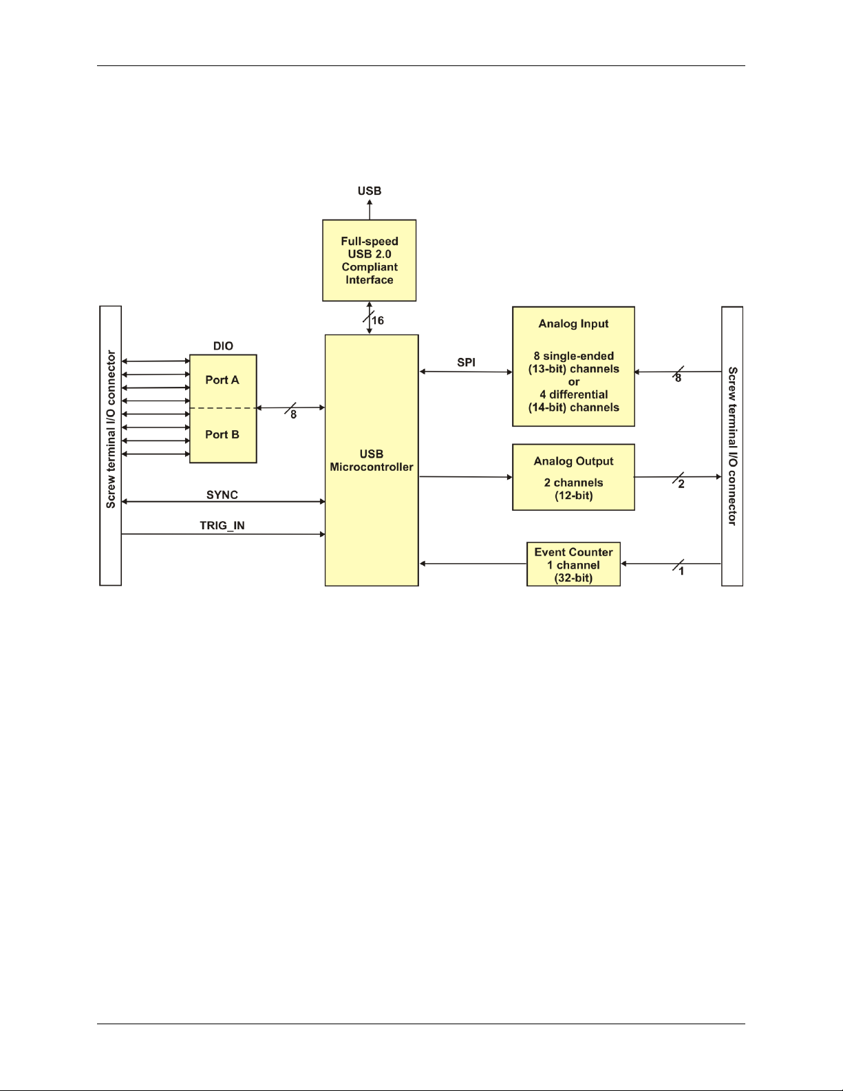
OM-USB-1408FS block diagram
OM-USB-1408FS functions are illustrated in the block diagram shown here.
Figure 2. OM-USB-1408FS functional block diagram
Software features
For information on the features of InstaCal and the other software included with your OM-USB-1408FS, refer
to the OMB-DAQ-2416 Series and OM-USB Series Data Acquisition Software User’s Guide that shipped with
your device.
7
Page 8

OM-USB-1408FS User's Guide Introducing the OM-USB-1408FS
Connecting a OM-USB-1408FS to your computer is easy
Installing a data acquisition device has never been easier.
The OM-USB-1408FS relies upon the Microsoft Human Interface Device (HID) class drivers. The HID
class drivers ship with every copy of Windows that is designed to work with USB ports. We use the
Microsoft HID because it is a standard, and its performance delivers full control and maximizes data
transfer rates for your OM-USB-1408FS. No third-party device driver is required.
The OM-USB-1408FS is plug-and-play. There are no jumpers to position, DIP switches to set, or interrupts
to configure.
You can connect the OM-USB-1408FS before or after you install the software, and without powering down
your computer first. When you connect an HID to your system, your computer automatically detects it and
configures the necessary software. You can connect and power multiple HID peripherals to your system
using a USB hub.
You can run up to two OM-USB-1408FS units on most computers.
You can connect your system to various devices using a standard four-wire cable. The USB connector
replaces the serial and parallel port connectors with one standardized plug and port combination.
You do not need a separate power supply module. The USB automatically delivers the electrical power
required by each peripheral connected to your system.
Data can flow two ways between a computer and peripheral over USB connections.
8
Page 9
Installing the OM-USB-1408FS
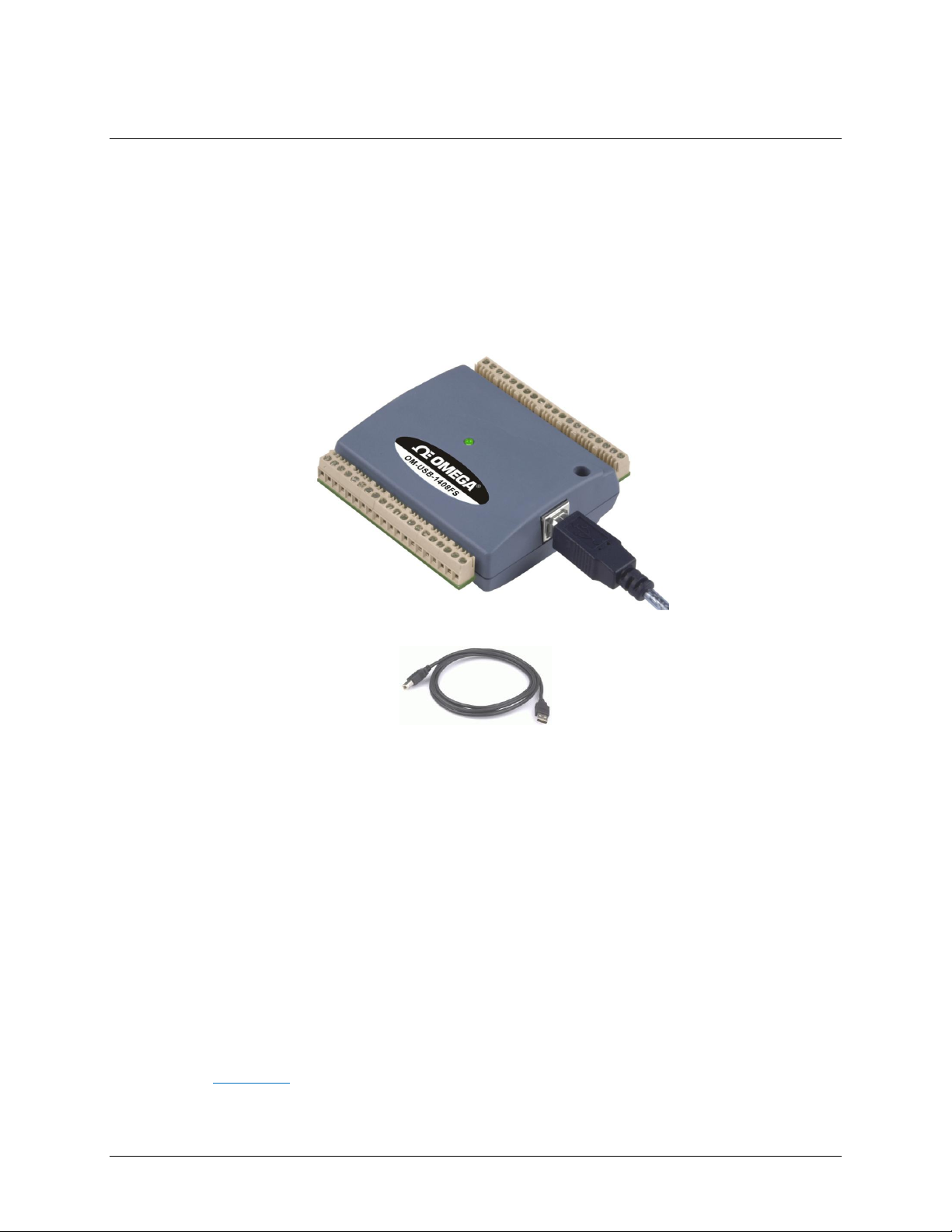
What comes with your OM-USB-1408FS shipment?
As you unpack your OM-USB-1408FS, verify that the following components are included.
Hardware
OM-USB-1408FS (shown with cable)
Chapter 2
USB cable (2 meter length)
Additional documentation
In addition to this hardware user's guide, you should also receive the OMB-DAQ-2416 Series and OM-USB
Series Data Acquisition Software User’s Guide. This booklet supplies a brief description of the software you
received with your OM-USB-1408FS and information regarding installation of that software. Please read this
booklet completely before installing any software or hardware.
Unpacking the OM-USB-1408FS
As with any electronic device, you should take care while handling to avoid damage from static
electricity. Before removing the OM-USB-1408FS from its packaging, ground yourself using a wrist strap or by
simply touching the computer chassis or other grounded object to eliminate any stored static charge.
If any components are missing or damaged, notify Omega Engineering immediately by phone, fax, or e-mail.
Phone: (203) 359-1660
Fax: (203) 359-7700
Email: das@omega.com
9
Page 10
OM-USB-1408FS User's Guide Installing the OM-USB-1408FS
Installing the software
Refer to the OMB-DAQ-2416 Series and OM-USB Series Data Acquisition Software User’s Guide for
instructions on installing the software on the OMB-DAQ-2416 Series and OM-USB Series Data Acquisition
Software CD. This booklet is available in PDF at http://www.omega.com/manuals/manualpdf/M4803.pdf.
We recommend that you download the latest Windows Update onto your computer before installing and
operating the OM-USB-1408FS.
Installing the hardware
Be sure you are using the latest system software
Before you install your OM-USB-1408FS, run Windows Update to update your operating system with the latest
HID and USB drivers.
To connect the OM-USB-1408FS to your system, turn your computer on, and connect the USB cable to a USB
port on your computer or to an external USB hub that is connected to your computer. The USB cable provides
power and communication to the OM-USB-1408FS.
When you connect the OM-USB-1408FS for the first time, a series of Found New Hardware popup balloons
(Windows XP) or dialogs (other Windows versions) open as the OM-USB-1408FS is detected by your
computer. This is normal. The last popup balloon or dialog states "Your new hardware is installed and ready to
use," and the LED on the OM-USB-1408FS should flash and then remain lit. This indicates that communication
is established between the OM-USB-1408FS and your computer.
You can install up to two OM-USB-1408FS units on most computers. If you need to connect more than two
OM-USB-1408FS units to your computer, contact Tech Support by phone, fax, or e-mail:
Phone: (203) 359-1660
Fax: (203) 359-7700
Email: das@omega.com
Caution! Do not disconnect any device from the USB bus while the computer is communicating with the
OM-USB-1408FS, or you may lose data and/or your ability to communicate with the OM-USB1408FS.
If the LED turns off
If the LED is illuminated but then turns off, the computer has lost communication with the OM-USB-1408FS.
To restore communication, disconnect the USB cable from the computer, and then reconnect it. This should
restore communication, and the LED should turn back on.
Allow the OM-USB-1408FS to operate for at least 30 minutes before using the device. This warm up time is
required to achieve the specified rated accuracy of measurements.
Calibrating the OM-USB-1408FS
The OM-USB-1408FS is shipped fully calibrated. Calibration coefficients are stored in EEPROM. Return the
device to Omega Engineering when calibration is required. The normal calibration interval is once per year.
10
Page 11
Chapter 3
Functional Details
Theory of operation - analog input acquisition modes
The OM-USB-1408FS can acquire analog input data in two different modes – software paced and continuous
scan.
Maximum throughput is system-dependent
Maximum throughput may be lower in Windows operating systems that predate Windows XP.
Software paced mode
In software paced mode, you can acquire one analog sample at a time. You initiate the A/D conversion by
calling a software command. The analog value is converted to digital and returned to the computer. You can
repeat this procedure until you have the total number of samples that you want from one channel.
The maximum throughput sample rate in software paced mode is system-dependent.
Continuous scan mode
In continuous scan mode, you can acquire data from up to eight channels. The analog data is continuously
acquired and converted to digital values until you stop the scan. Data is transferred in blocks of 31 samples from
the OM-USB-1408FS to the memory buffer on your computer.
The maximum continuous scan rate of 48 kS/s is an aggregate rate. The total acquisition rate for all channels
cannot exceed 48 kS/s. You can acquire data from one channel at 48 kS/s, two channels at 24 kS/s, and four
channels at 12 kS/s. You can start a continuous scan with either a software command or with an external
hardware trigger event.
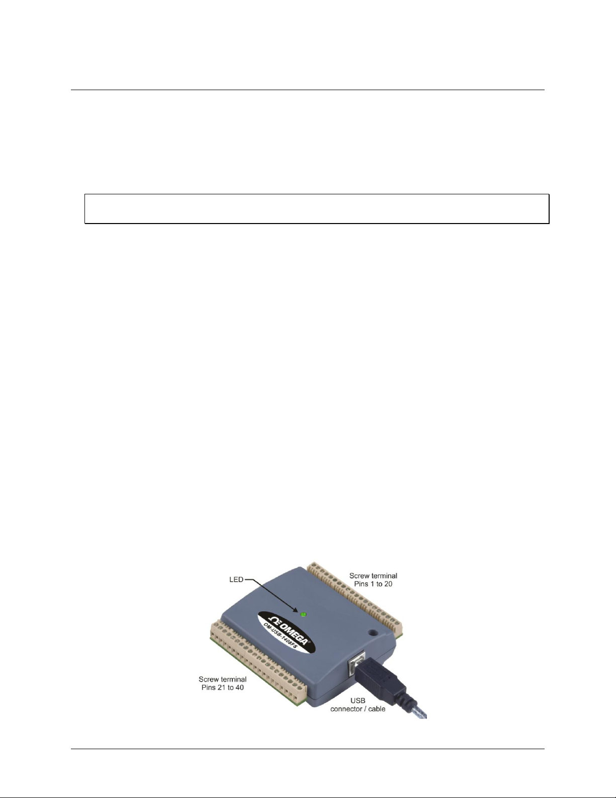
External components
The OM-USB-1408FS has the following external components, as shown in Figure 3.
USB connector
LED
Screw terminal banks (2)
Figure 3. OM-USB-1408FS external components
11
Page 12
OM-USB-1408FS User's Guide Functional Details
LED Illumination
Indication
Steady green
The OM-USB-1408FS is connected to a computer or external USB hub.
Blinks continuously
Data is being transferred.
USB connector
The USB connector is on the right side of the OM-USB-1408FS. This connector provides +5 V power and
communication. The voltage supplied through the USB connector is system-dependent, and may be less than
5 V. No external power supply is required.
LED
The LED on the front of the housing indicates the communication status of the OM-USB-1408FS. It uses up to
5 mA of current and cannot be disabled. The table below defines the function of the OM-USB-1408FS LED.
LED Illumination
Screw terminal wiring
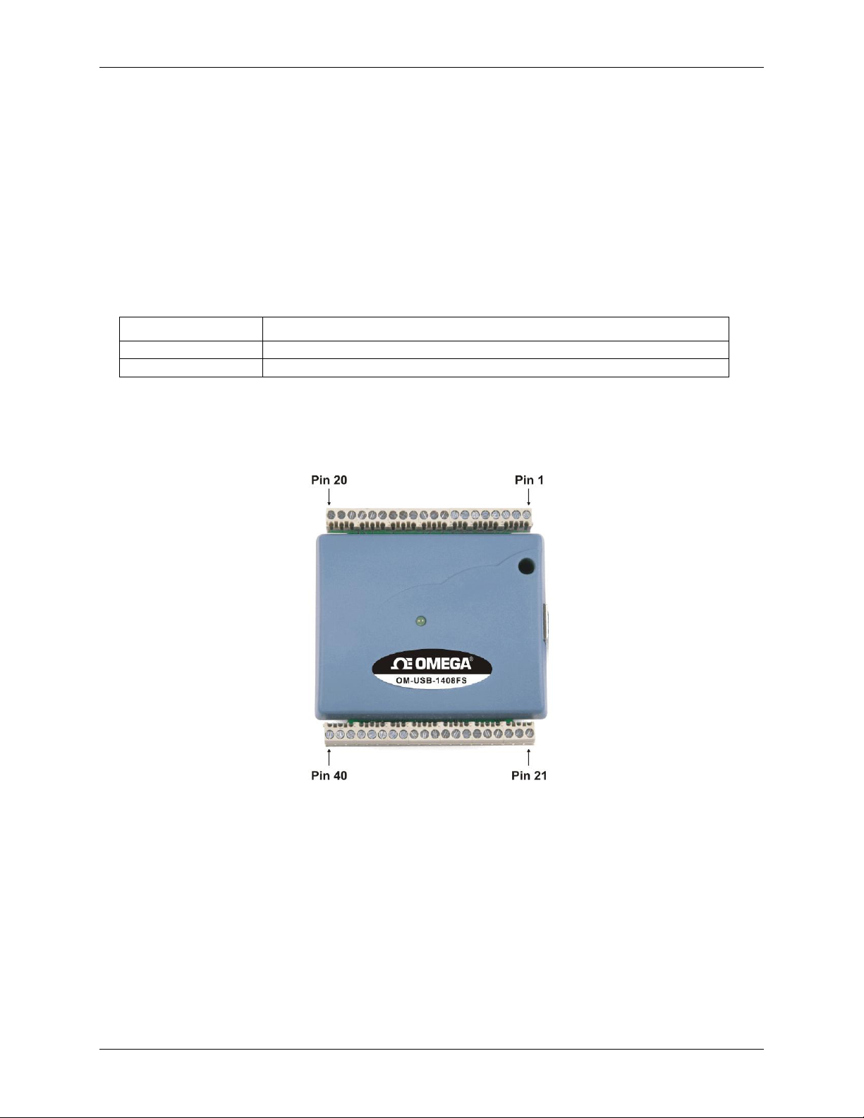
The OM-USB-1408FS has two rows of screw terminals—one row on the top edge of the housing, and one row
on the bottom edge. Each row has 20 connections. Pin numbers are identified in Figure 4.
Figure 4. OM-USB-1408FS Screw terminal pin numbers
Screw terminal – pins 1-20
The screw terminals on the top edge of the OM-USB-1408FS (pins 1 to 20) provide the following connections:
Eight analog input connections (CH0 IN to CH7 IN)
Two analog output connections (D/A OUT 0 to D/A OUT 1)
One external trigger source (TRIG_IN)
One SYNC terminal for external clocking and multi-unit synchronization (SYNC)
One voltage output source (2.5VREF)
Five analog ground connections (AGND)
One ground connection (GND)
One external event counter connection (CTR)
12
Page 13
OM-USB-1408FS User's Guide Functional Details
Connector type
Screw terminal
Wire gauge range
16 AWG to 30 AWG
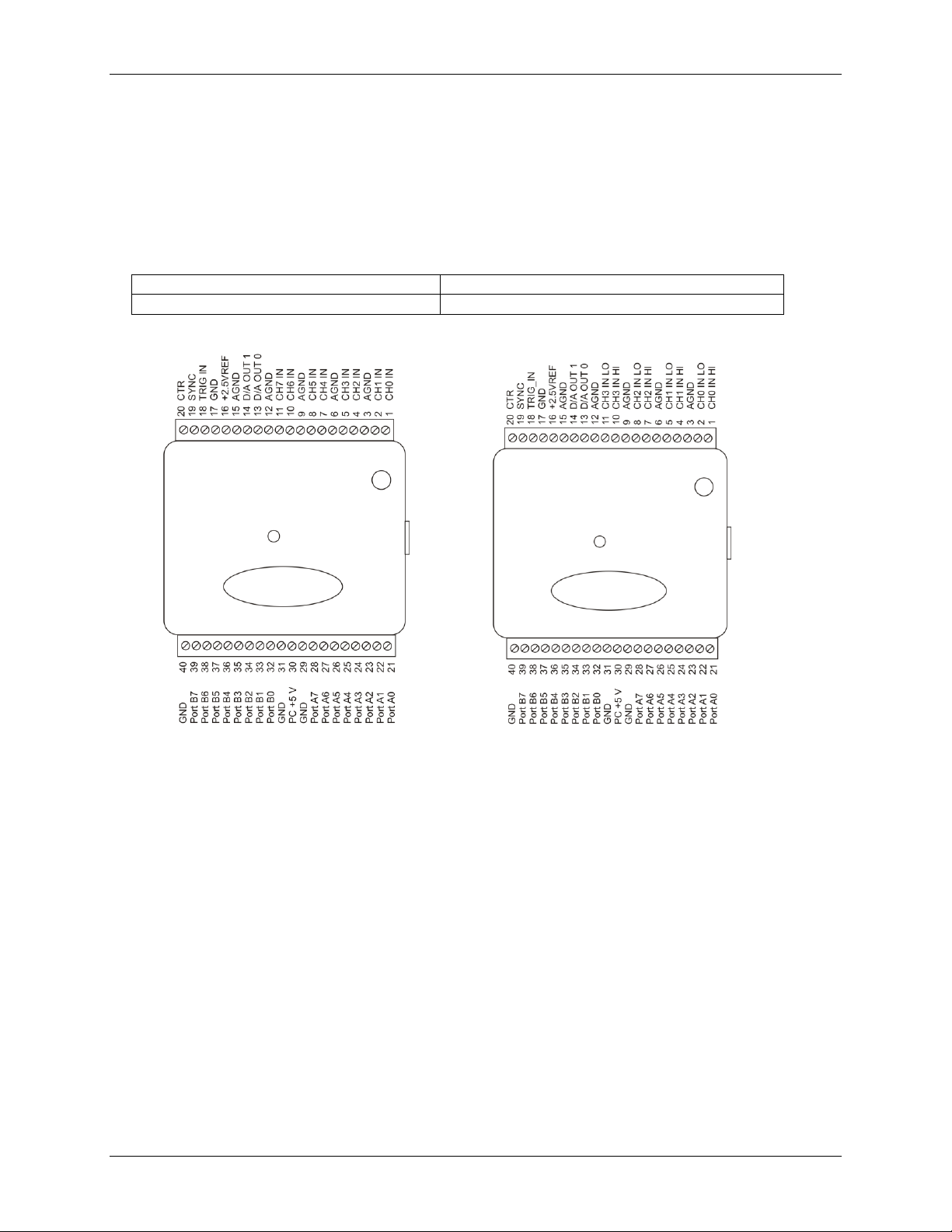
8-channel single-ended mode pin out
4-channel differential mode pin out
Screw terminal – pins 21-40
The screw terminals on the bottom edge of the (pins 21 to 40) provide the following connections:
16 digital I/O connections (PortA0 to Port A7, and Port B0 to Port B7)
One power connection (PC+5 V)
Three ground connections (GND)
Main connector and pin out
Analog input terminals (CH0 IN - CH7 IN)
You can connect up to eight analog input connections to the screw terminal containing pins 1 to 20 (CH0 IN
through CH7 IN.) Refer to the pinout diagrams above for the location of these pins.
You can configure the analog input channels as eight single-ended channels or four differential channels. When
configured for differential mode, each analog input has 14-bit resolution. When configured for single-ended
mode, each analog input has 13-bit resolution, due to restrictions imposed by the A/D converter.
Single-ended configuration
When all of the analog input channels are configured for single-ended input mode, eight analog channels are
available. The input signal is referenced to signal ground (GND), and delivered through two wires:
The wire carrying the signal to be measured connects to CH# IN.
The second wire connects to AGND.
The input range for single-ended mode is ±10 V. No other ranges are supported in this mode.
13
Page 14
OM-USB-1408FS User's Guide Functional Details
Single-ended measurements using differential channels
To perform a single-ended measurement using differential channels, connect the signal to CHn IN HI input, and
ground the associated CHn IN LO input.
Differential configuration
When all of the analog input channels are configured for differential input mode, four analog channels are
available. In differential mode, the input signal is measured with respect to the low input.
The input signal is delivered through three wires:
The wire carrying the signal to be measured connects to CH0 IN HI, CH1 IN HI, CH2 IN HI, or
CH3 IN HI.
The wire carrying the reference signal connects to CH0 IN LO, CH1 IN LO, CH2 IN LO, or CH3 IN LO.
The third wire connects to GND.
A low-noise precision programmable gain amplifier (PGA) is available on differential channels to provide gains
of up to 20 and a dynamic range of up to 14-bits. Differential mode input voltage ranges are ±20 V, ±10 V,
±5 V, ±4 V, ±2.5 V, ±2.0 V, ±1.25 V, and ±1.0 V.
In differential mode, the following two requirements must be met for linear operation:
Any analog input must remain in the −10V to +20V range with respect to ground at all times.
The maximum differential voltage on any given analog input pair must remain within the selected voltage
range.
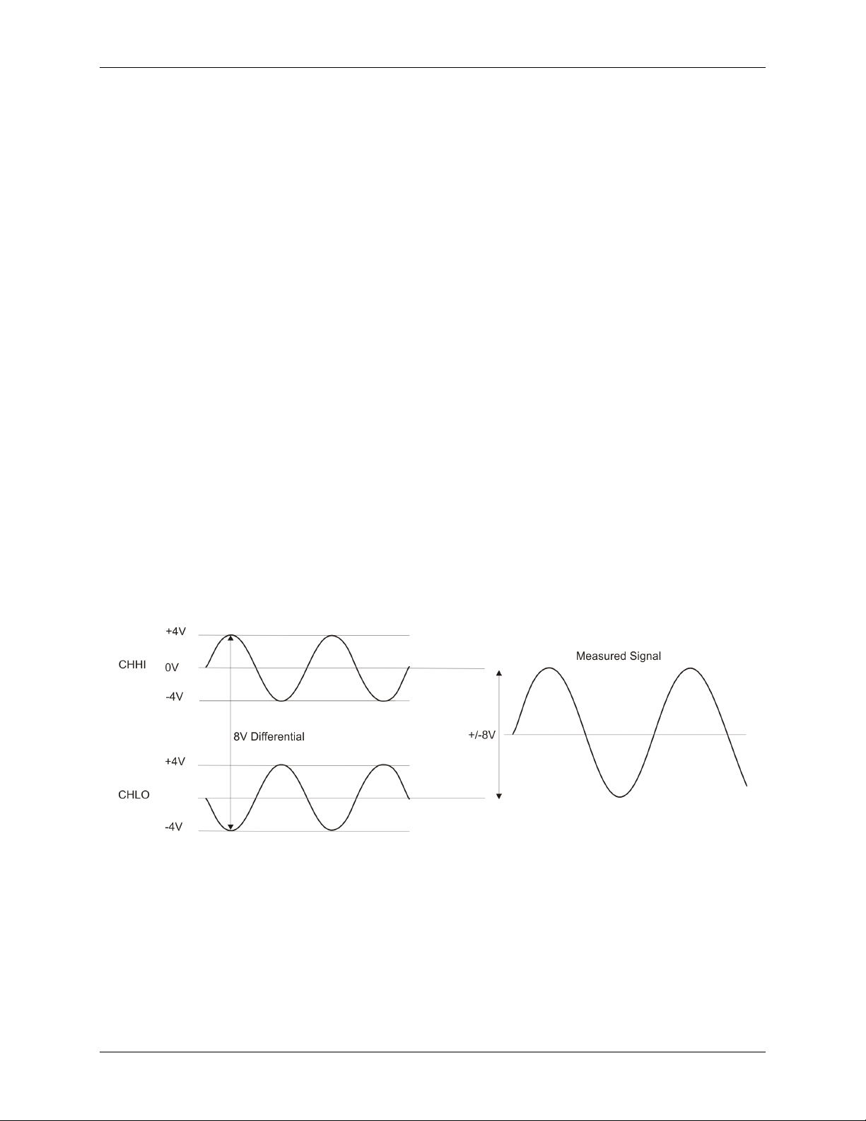
The input [common-mode voltage + signal] of the differential channel must be in the
−10 V to +20 V range in order to yield a useful result. For example, you input a 4 V pp sine wave to CHHI, and
apply the same sine wave 180° out of phase to CHLO. The common mode voltage is 0 V. The differential input
voltage swings from 4 V− (−4 V) = 8 V to (−4 V) − 4 V = −8V. Both inputs satisfy the
−10 V to +20 V input range requirement, and the differential voltage is suited for the ±10 V input range (see
Figure 5).
Figure 5. Differential voltage example: common mode voltage of 0 V
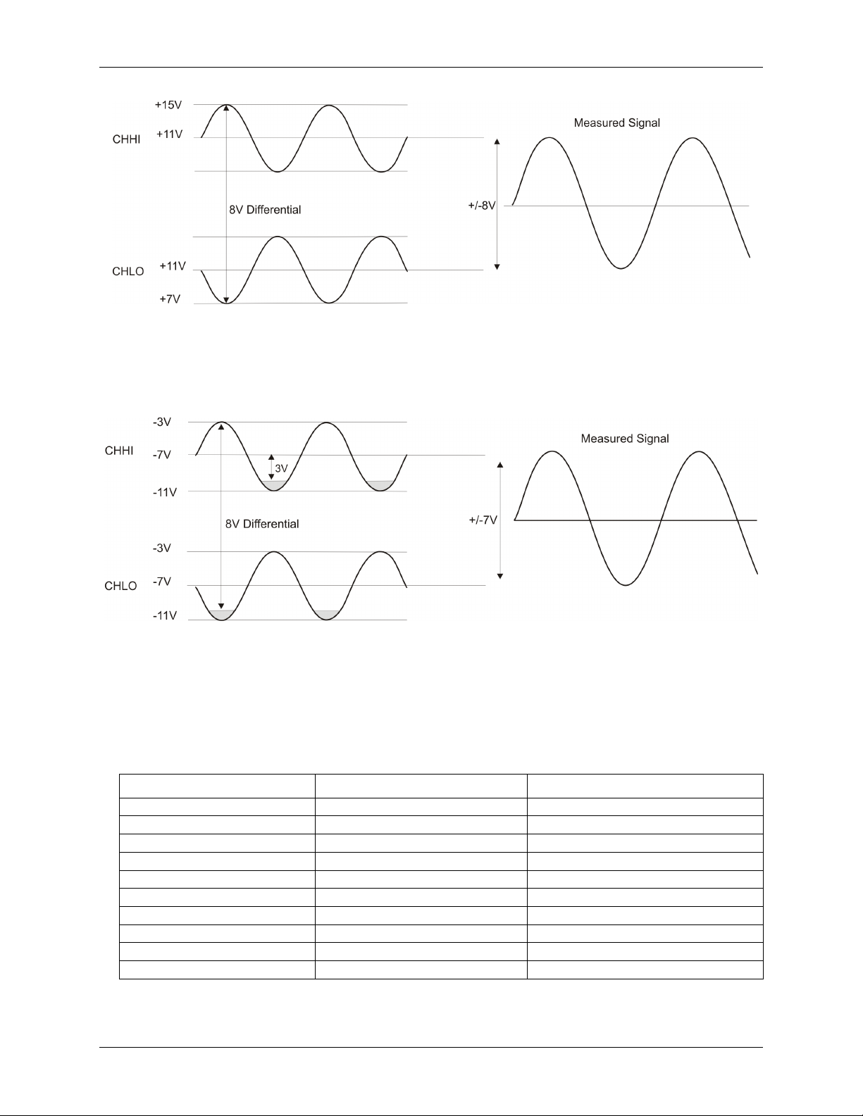
If you increase the common mode voltage to 11 V, the differential remains at ±8 V. Although the [commonmode voltage + signal] on each input now has a range of +7 V to +15 V, both inputs still satisfy the −10 V to
+20 V input requirement (see Figure 6).
14
Page 15
OM-USB-1408FS User's Guide Functional Details
CHHI
CHLO
Result
−20 V
0 V
In Valid
−15 V
+5 V
In Valid
−10 V
0 V
−10 V
−10 V
+10 V
−20 V
0 V
+10 V
−10 V
0 V
+20 V
−20 V
+10 V
−10 V
+20 V
+10 V
0 V
+10 V
+15 V
−5 V
+20 V
+20 V
0
+20 V
Figure 6. Differential voltage example: common mode voltage of 11 V
If you decrease the common-mode voltage to −7 V, the differential stays at ±8 V. However, the solution now
violates the input range condition of −10 V to +20 V. The voltage on each analog input now swings from −3V
to −11V. Voltages between −10 V and −3 V are resolved, but those below -10 V are clipped (see Figure 7).
Figure 7. Differential voltage example: common mode voltage of -7 V
Since the analog inputs are restricted to a −10 V to +20 V signal swing with respect to ground, all ranges except
±20V can realize a linear output for any differential signal with zero common mode voltage and full scale signal
inputs. The ±20 V range is the exception. You cannot put −20 V on CHHI and 0 V on CHLO since this violates
the input range criteria. The following table shows some possible inputs and the expected results.
Sample inputs and differential results
15
Page 16
OM-USB-1408FS User's Guide Functional Details
For more information on analog signal connections
For more information on single-ended and differential inputs, refer to the the OMB-DAQ-2416 Series and OMUSB Series General Guide to Signal Connections (available on our web site at
www.omega.com/manuals/manualpdf/M4830.pdf).
Analog output terminals (D/A OUT 0 and D/A OUT 1)
You can connect up to two analog output connections to the screw terminal pins 13 and 14 (D/A OUT 0 and D/A
OUT 1). Refer to the pinout diagrams on page 13 for the location of these pins.
Each channel can be paced individually at rates up to 10,000 updates per second. Both channels can be paced
simultaneously using the same time base at 5000 updates per channel. The 0-4.096 V output range provides a
convenient 1 mV per LSB when setting the output voltage levels.
Digital I/O terminals (Port A0 to A7, and Port B0 to B7)
You can connect up to 16 digital I/O lines to the screw terminal containing pins 21 to 40 (Port A0 to Port A7,
and Port B0 to Port B7.) Refer to the pinout diagrams on page 13 for the location of these pins. You can
configure each digital port for either input or output.
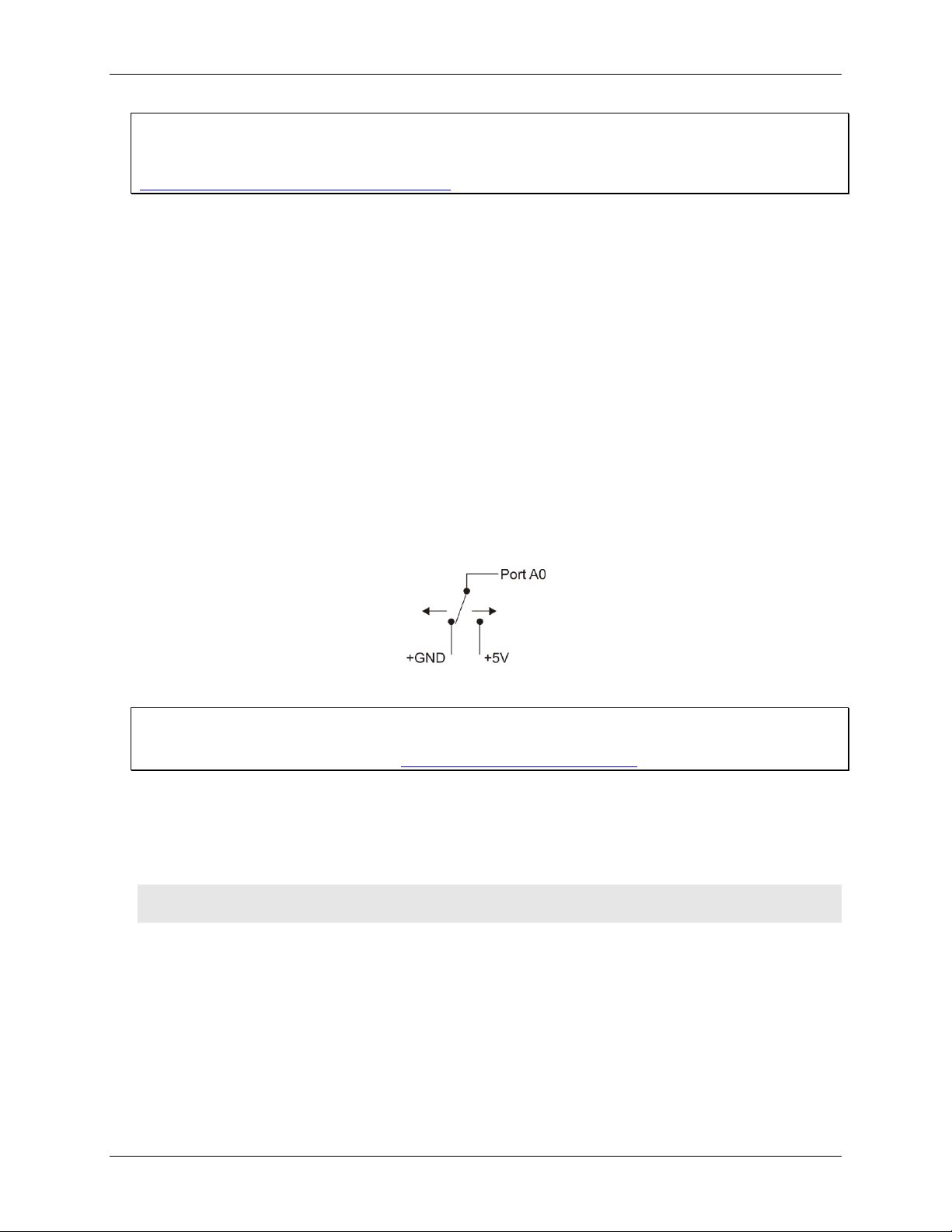
When you configure the digital bits for input, you can use the digital I/O terminals to detect the state of any
TTL level input. Refer to the schematic shown in Figure 8. If the switch is set to the +5 V input, Port A0 reads
TRUE (1). If you move the switch to GND, Port A0 reads FALSE.
Figure 8. Schematic showing switch detection by digital channel Port A0
For more information on digital signal connections
For more information on digital signal connections and digital I/O techniques, refer to the Guide to Signal
Connections (available on our web site at www.mccdaq.com/signals/signals.pdf).
Power terminals
The PC +5V connection (pin 30) draws power from the USB connector. This terminal is a 5 V output that is
supplied by the host computer. Refer to the pinout diagrams on page 13 for the location of this pin.
Caution! The +5 V terminal is an output. Do not connect to an external power supply or you may damage
the OM-USB-1408FS and possibly the computer.
The maximum total output current that can be drawn from all OM-USB-1408FS connections (power, analog
and digital outputs) is 420 mA. This maximum applies to most personal computers and self-powered USB hubs.
Bus-powered hubs and notebook computers may limit the maximum available output current to 100 mA.
Just connecting the OM-USB-1408FS to your computer draws 80 mA of current from the USB +5 V supply.
Once you start running applications with the OM-USB-1408FS, each DIO bit can draw up to 2.5 mA, and each
analog output can draw 15 mA. The maximum amount of +5 V current available for experimental use, over and
above that required by the OM-USB-1408FS, is the difference between the total current requirement of the
USB (based on the application), and the allowed current draw of the PC platform (500 mA for desktop PCs and
self-powered hubs, or 100 mA for bus-powered hubs and notebook computers).
16
Page 17

OM-USB-1408FS User's Guide Functional Details
With all outputs at their maximum output current, you can calculate the total current requirement of the OMUSB-1408FS USB +5 V supply as follows:
(OM-USB-1408FS @ 80 mA) + (16 DIO @ 2.5 mA ea) + (2 AO @ 15 mA ea ) = 150 mA
For an application running on a PC or powered hub, the maximum available excess current is
500 mA − 150 mA = 350 mA. This number is the total maximum available current at the PC +5 V screw
terminals. Measurement Computing highly recommends that you figure in a safety factor of 20% below this
maximum current loading for your applications. A conservative, safe user maximum in this case would be
280 mA.
Since laptop computers typically allow up to 100 mA, the OM-USB-1408FS in a fully-loaded configuration
may be above that allowed by the computer. In this case, you must determine the per-pin loading in the
application to ensure that the maximum loading criteria is met. The per-pin loading is calculated by simply
dividing the +5 V by the load impedance of the pin in question.
External trigger terminal
The TRIG_IN connection (pin 18) can be configured for either rising or falling edge. Refer to the pinout
diagrams on page 13 for the location of this pin.
Counter terminal
The CTR connection (pin 20) is input to the 32-bit external event. Refer to the pinout diagrams on page 13 for
the location of this pin. The internal counter increments when the TTL levels transition from low to high. The
counter can count frequencies of up to 1 MHz.
+2.5VREF terminal
The +2.5VREF connection (pin 16) is an output terminal that supplies 2.5 volts.
SYNC terminal
The SYNC connection (pin 19) is a bidirectional I/O signal. You can use it for two purposes:
Configure as an external clock input to externally source the A/D conversions. The SYNC terminal
supports TTL-level input signals of up to 48 kHz.
Configure as an output to synchronize with a second OM-USB-1408FS and acquire data from 16 channels.
For information on synchronizing multiple units, refer to page 21.
Ground terminals
The four analog ground (AGND) connections provide a common ground for all OM-USB-1408FS input
channels. Four ground (GND) connections provide a common ground for the DIO, TRIG_IN, CTR, SYNC and
PC +5V connections. Refer to the pinout diagrams on page 13 for the location of these pins.
Accuracy
The overall accuracy of any instrument is limited by the error components within the system. Quite often,
resolution is incorrectly used to quantify the performance of a measurement product. While "14-bits" or "1 part
in 16383" does indicate what can be resolved, it provides little insight into the quality of an absolute
measurement. Accuracy specifications describe the actual results that can be realized with a measurement
device.
17
Page 18
OM-USB-1408FS User's Guide Functional Details
There are three types of errors which affect the accuracy of a measurement system:
offset
gain
nonlinearity
The primary error sources in the OM-USB-1408FS are offset and gain. Nonlinearity is small in the OM-USB1408FS, and is not significant as an error source with respect to offset and gain.
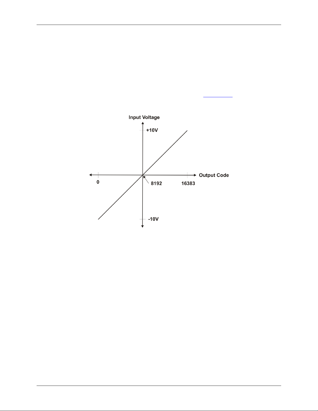
Figure 9 shows an example of an ideal, error-free, OM-USB-1408FS transfer function. The typical calibrated
accuracy of the OM-USB-1408FS is range-dependent, as explained in the "Specifications" chapter on page 22.
We use a ±10 V range here as an example of what you can expect when performing a measurement in this
range.
Figure 9. Ideal ADC transfer function
The offset error is measured at mid-scale. Ideally, a zero volt input should produce an output code of 8192. Any
deviation from this is an offset error.
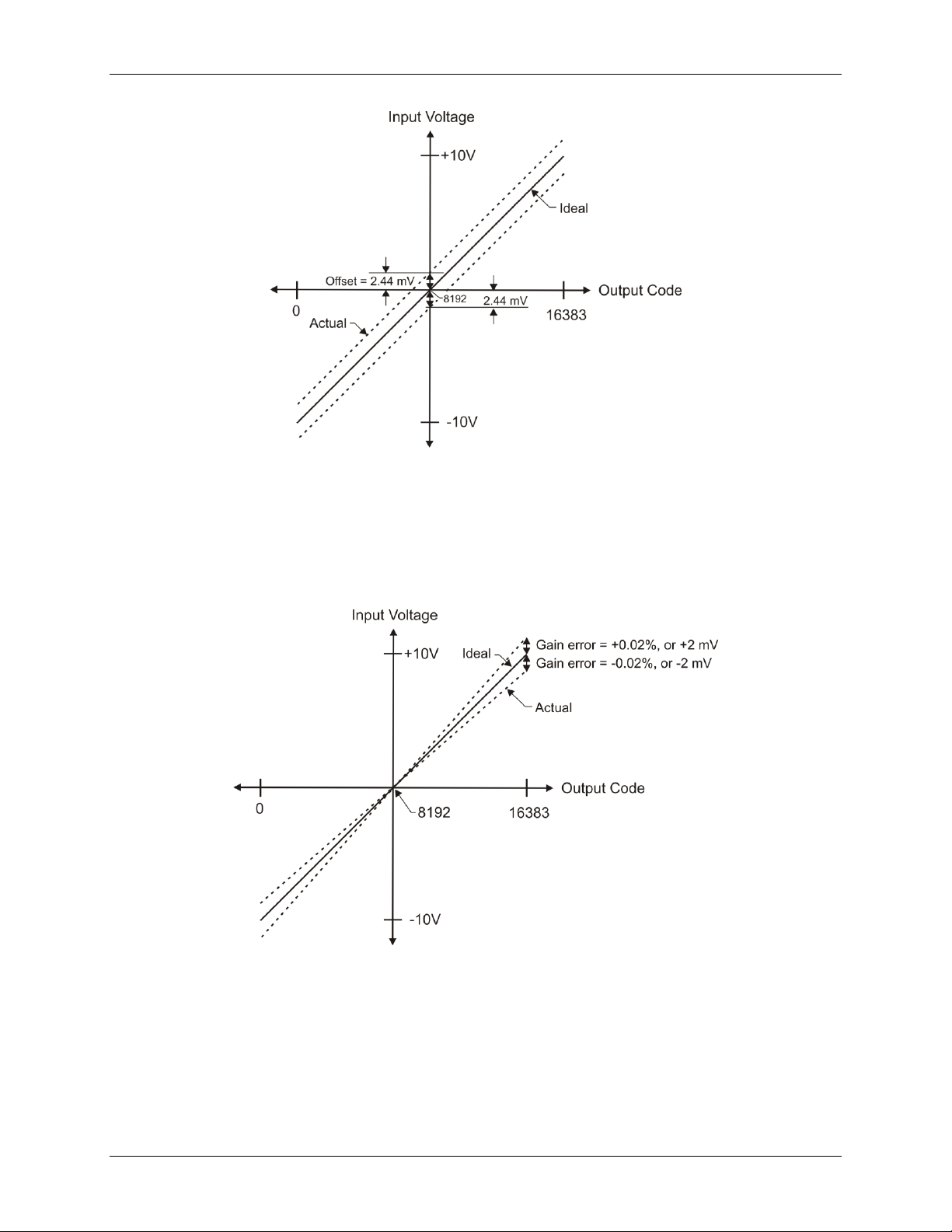
Figure 10 shows an example of a OM-USB-1408FS transfer function with a ±2.44 mV offset error. Offset error
affects all codes equally by shifting the entire transfer function up or down along the input voltage axis.
The accuracy plots in Figure 10 are drawn for clarity and are not drawn to scale.
18
Page 19
OM-USB-1408FS User's Guide Functional Details
Figure 10. ADC transfer function with offset error
Gain error is a change in the slope of the transfer function from the ideal, and is typically expressed as a
percentage of full-scale. Figure 11 shows the OM-USB-1408FS transfer function with gain error. Gain error is
easily converted to voltage by multiplying the full-scale (FS) input by the error.
The accuracy plots in Figure 11 are drawn for clarity and are not drawn to scale.
Figure 11. ADC Transfer function with gain error
Figure 11 shows an example of a OM-USB-1408FS transfer function with a calibrated gain error of ±0.02%, or
±2 mV. This means that at full scale, neglecting the effect of offset for the moment, the measurement would be
within 2 mV of the actual value. Note that gain error is expressed as a ratio. Values near ±FS are more affected
from an absolute voltage standpoint than are values near mid-scale, which see little or no voltage error.
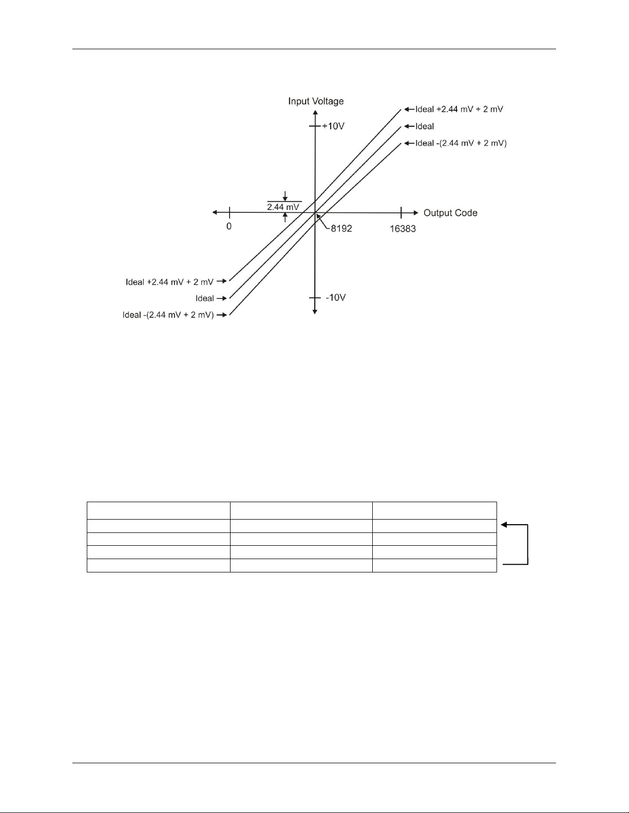
Combining these two error sources in Figure 12, we have a plot of the error band of the OM-USB-1408FS for
the ±10 V range. This is a graphical version of the typical accuracy specification of the product.
19
Page 20
OM-USB-1408FS User's Guide Functional Details
Element
Channel
Range
0
CH0
BIP10V
1
CH3
BIP5V
2
CH1
BIP10V
3
CH2
BIP1V
The accuracy plots in Figure 12 are drawn for clarity and are not drawn to scale
Figure 12. Error band plot
OM-USB-1408FS channel gain queue feature
The OM-USB-1408FS's channel gain queue feature allows you to set up a scan sequence with a unique perchannel gain setting and channel sequence.
The channel gain queue feature removes the restriction of using an ascending channel sequence at a fixed gain.
This feature creates a channel list which is written to local memory on the OM-USB-1408FS. Each element of
the channel list is made up of a channel number and range setting. An example of a four-element list is shown in
the table below.
Sample channel gain queue list
When a scan begins with the gain queue enabled, the OM-USB-1408FS reads the first element, sets the
appropriate channel number and range, and then acquires a sample. The properties of the next element are then
retrieved, and another sample is acquired. This sequence continues until all elements in the gain queue have
been selected. When the end of the channel list is detected, the sequence returns to the first element in the list.
This sequence repeats until the specified number of samples is gathered. You must carefully match the gain to
the expected voltage range of the associated channel — otherwise, an over range condition can occur. Although
this condition does not damage the OM-USB-1408FS, it does produce a useless full-scale reading. It can also
introduce a long recovery time from saturation, which can affect the next measurement in the queue.
20
Page 21
OM-USB-1408FS User's Guide Functional Details
Synchronizing multiple units
You can run up to two OM-USB-1408FS units on most computers.
You can connect the SYNC pin of two OM-USB-1408FS units together in a master/slave configuration and
acquire data from the analog inputs of both devices using one clock. When the SYNC pin is configured as an
output, the internal A/D pacer clock is sent to the screw terminal. You can use this signal as a clock input to a
second OM-USB-1408FS by connecting it to the SYNC pin of the second OM-USB-1408FS.
When used as a clock input, the SYNC pin operates in one of two modes – Continuous or Gated. The mode is
software-selectable using InstaCal.
In the default Continuous mode, the OM-USB-1408FS ignores the first clock pulse in order to ensure adequate
setup time. Use this mode if the unit is being paced from a continuous clock source, such as a generator.
In the Gated mode, it is assumed that the clock signal will be held off for an adequate amount of time for setup
to occur. No clock pulses are ignored. Use this mode if you want to use the OM-USB-1408FS unit as a slave,
and the source of the external clock is another USB unit.
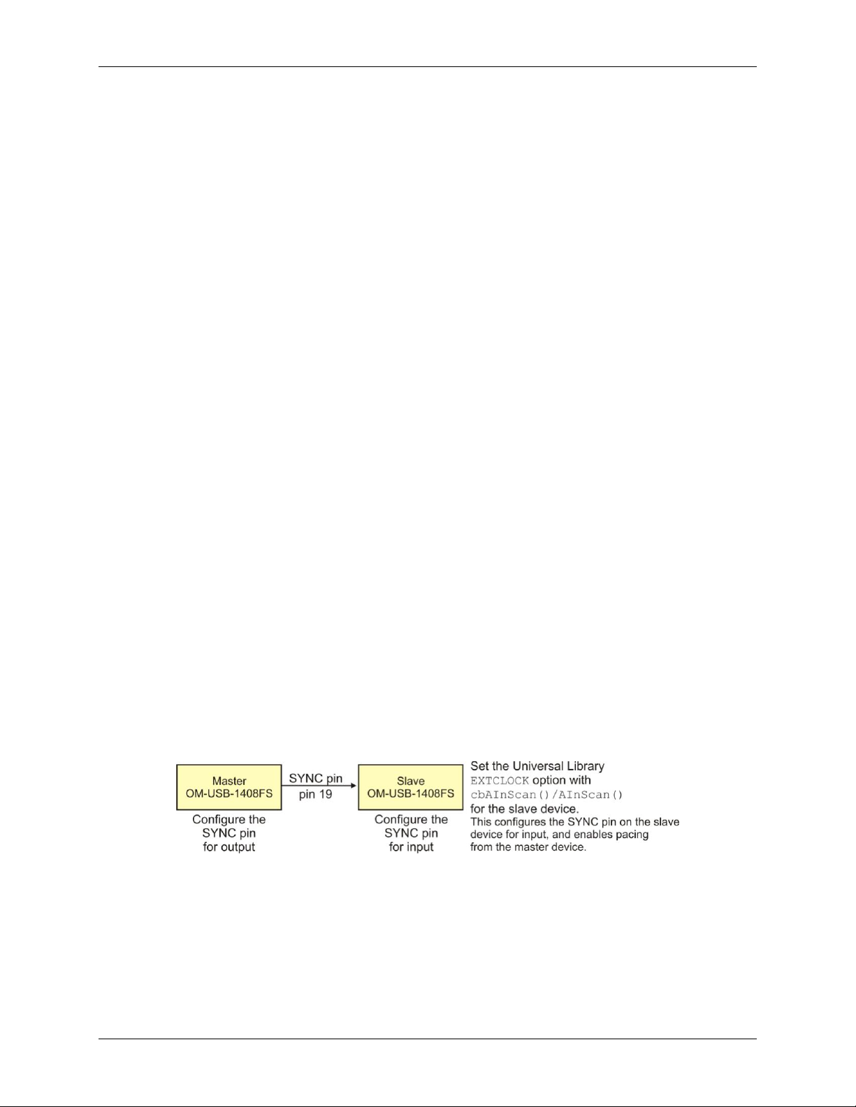
The SYNC pin (pin 19) is set for pacer output by default. To set it for input requires a software command (see
Figure 13 below).
To synchronize a master OM-USB-1408FS with a slave OM-USB-1408FS and acquire data from the analog
inputs of both devices using one clock, follow the steps below.
1. Connect the SYNC pin of the master OM-USB-1408FS to the SYNC pin of the slave OM-USB-1408FS.
2. Run InstaCal.
3. From the PC Board List on the InstaCal main form, double-click on the OM-USB-1408FS you want to use
as a slave. The Board Configuration dialog opens.
4. Select Gated from the Ext. Clock Type drop-down list.
5. Set the Universal Library EXTCLOCK option with cbAInScan()/AInScan for the slave OM-USB-1408FS
to enable pacing from the master USB device.
This InstaCal option does not affect internally paced acquisition. It only affects scans that use the EXTCLOCK
option.
An example of a master/slave configuration is shown here.
Figure 13. Configuring for synchronous data acquisition
When you are operating one OM-USB-1408FS, do not set the EXTCLOCK option unless you are using an
external clock for A/D pacing.
21
Page 22
Parameter
Conditions
Specification
A/D converter type
Successive approximation type
Input voltage range for linear operation, single-ended
mode
CHx to GND
±10 volts (V) max
Input common-mode voltage range for linear operation,
differential mode
CHx to GND
–10 V min, +20 V max
Absolute maximum input voltage
CHx to GND
±28 V max
Input impedance
122K Ohms
Input current (Note 1)
Vin = +10 V
70 microamperes (µA) typ
Vin = 0 V
–12 µA typ
Vin = –10 V
–94 µA typ
Number of channels
8 single-ended / 4 differential, software
selectable
Input ranges, single-ended mode
±10 V, G=2
Input ranges, differential mode
±20 V, G=1
±10 V, G=2
±5 V, G=4
±4 V, G=5
±2.5 V, G=8
±2.0 V, G=10
±1.25 V, G=16
±1.0 V, G=20
Software selectable
Throughput (Note 2)
Software paced
250 samples per second (S/s) typ,
PC-dependent
Continuous scan
48 kilosamples per second (kS/s)
Channel gain queue
Up to 16
elements
Software configurable channel, range,
and gain.
Resolution (Note 3)
Differential
14-bits, no missing codes
Single-ended
13-bits
Integral linearity error
±2 least significant bit (LSB) typ
Differential linearity error
±0.5 LSB typ
Absolute accuracy long term drift
(Note 4)
±20V range
±3LSB typ. (delta t = 1000 hrs)
±4V range
±6LSB typ. (delta t = 1000 hrs)
±1V range
±8LSB typ. (delta t = 1000 hrs)
2.5VREF accuracy (pin 16)
±36.25 mV max.
2.5VREF output current (pin 16)
Source
5 mA max.
Sink
20 µA min, 100 µA typ
Trigger source
Software
selectable
External digital: TRIG_IN
Specifications
All specifications are subject to change without notice.
Typical for 25°C unless otherwise specified.
Specifications in italic text are guaranteed by design.
Analog input
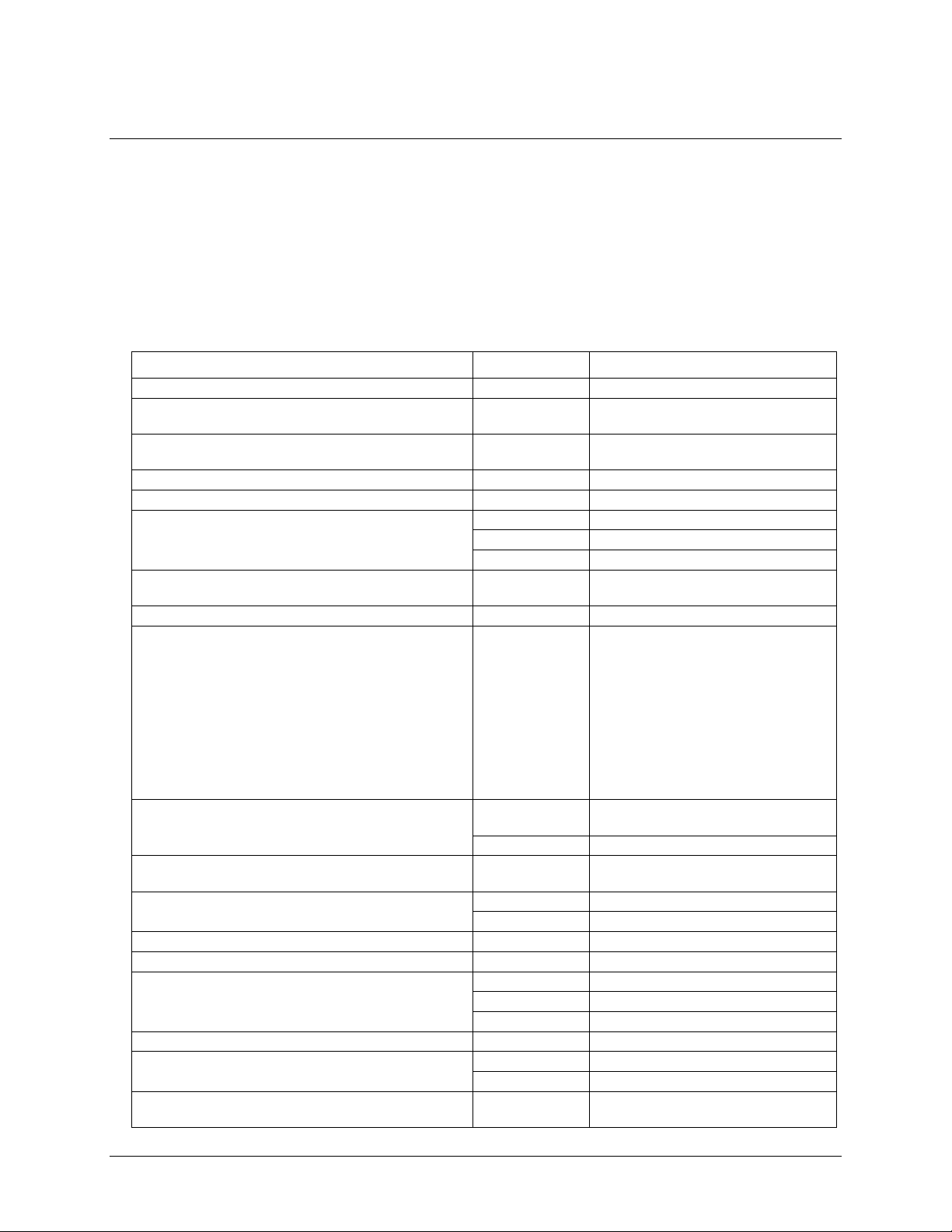
Table 1. Analog input specifications
Chapter 4
22
Page 23
OM-USB-1408FS User's Guide Specifications
Range
Absolute Accuracy 25°C (±mV)
Absolute Accuracy 0 to 50°C (±mV)
±20 V
10.98
49.08
±10 V
7.32
33.42
±5 V
3.66
20.76
±4 V
2.92
19.02
±2.5 V
1.83
14.97
±2 V
1.70
14.29
±1.25 V
1.21
12.18
±1 V
1.09
11.63
Range
Absolute Accuracy 25°C (±mV)
Absolute Accuracy 0 to 50°C (±mV)
±10 V
10.98
49.08
Range
Typical counts
Least significant bit
root mean square
(LSB
rms)
±20 V
8
1.21
±10 V
8
1.21
±5 V
9
1.36
±4 V
10
1.51
±2.5 V
12
1.81
±2 V
14
2.12
±1.25 V
18
2.72
±1 V
22
3.33
Range
Typical Counts
LSB
rms
±10 V
8.0
1.21
Note 1: Input current is a function of applied voltage on the analog input channels. For a given input
voltage, Vin, the input leakage is approximately equal to (8.181*Vin-12) µA.
Note 2: Maximum throughput scanning to PC memory is machine dependent. The rates specified are for
Windows XP only. Maximum rates on operating systems that predate XP may be less and must
be determined through testing on your machine
Note 3: The ADS7871 converter only returns 13-bits (0 to 8192 codes) in single-ended mode.
Note 4: Extrapolating the long term drift accuracy specifications will provide the approximate long term
drift of the OM-USB-1408FS intermediate input ranges.
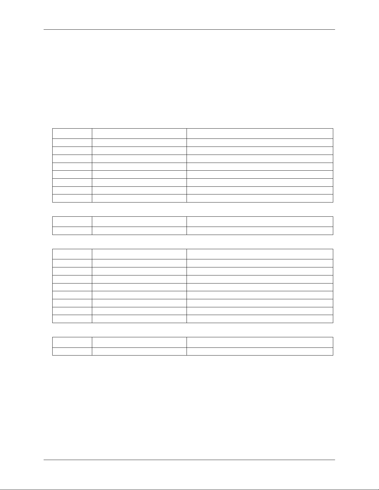
Table 2. Accuracy, differential mode
Table 3. Accuracy, single-ended mode
Table 4. Noise performance, differential mode
Table 5. Noise performance, single-ended mode
23
Page 24
OM-USB-1408FS User's Guide Specifications
Parameter
Conditions
Specification
Resolution
12-bits, 1 in 4096
Output range
0 to 4.096 V, 1 mV per LSB.
Number of channels
2
Throughput (Note 5)
Software paced
250 S/s single channel typical, PC dependent
Single channel, continuous scan
10 kS/s
Dual channel, continuous scan,
simultaneous update
5 kS/s
Power on and reset voltage
0V, ±20 mV typ. (initializes to 000h code)
Output drive
Each D/A OUT
±15 mA
Slew rate
0.8 V/microsecond (µs) typ
Range
Accuracy (±LSB)
0 to 4.096 V
4.0 typ, 45.0 max
Range
% of FSR (±)
Gain Error at FS (±mV)
Offset (±mV)
(Note 6)
Accuracy at FS (±mV)
0 to 4.096 V
0.1 typ, 0.9 max
4.0 typ, 36.0 max
1.0 typ, 9.0 max
4.0 typ, 45.0 max
Digital type
CMOS
Number of I/O
16 (Port A0 through A7, Port B0 through B7)
Configuration
2 banks of 8
Pull-up/pull-down
configuration
All pins pulled up to Vs via 47 K resistors (default). Positions available for pull-down to
ground. Hardware selectable via zero ohm (Ω) resistors as a factory option.
Input high voltage
2.0 V min, 5.5 V absolute max
Input low voltage
0.8 V max, –0.5 V absolute min
Output high voltage
(IOH = –2.5 mA)
3.8 V min
Output low voltage
(IOL = 2.5 mA)
0.7 V max
Power on and reset state
Input
Analog output
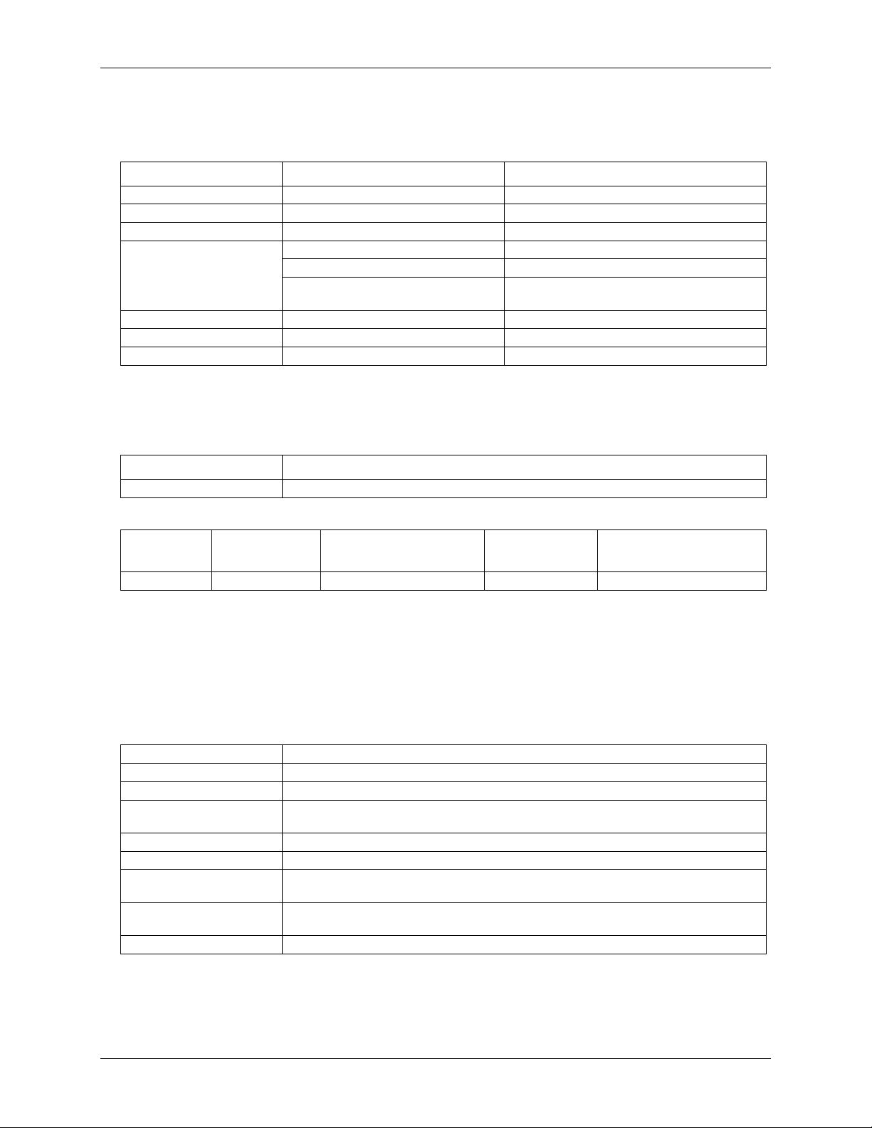
Table 6. Analog output specifications
Note 5: Maximum throughput scanning from PC memory is machine dependent. The rates specified are
for Windows XP only. Maximum rates on operating systems that predate XP may be less and
must be determined through testing on your machine.
Table 7. Analog output accuracy
Note 6: Zero-scale offsets may result in a fixed zero-scale error producing a "dead-band” digital input
code region.. In this case, changes in digital input code at values less than 0x040 may not
produce a corresponding change in the output voltage. The OM-USB-1408FS offset error is
tested and specified at code 0x040.
Digital input/output
Table 8. Analog output accuracy components
Table 9. Digital I/O specifications
24
Page 25
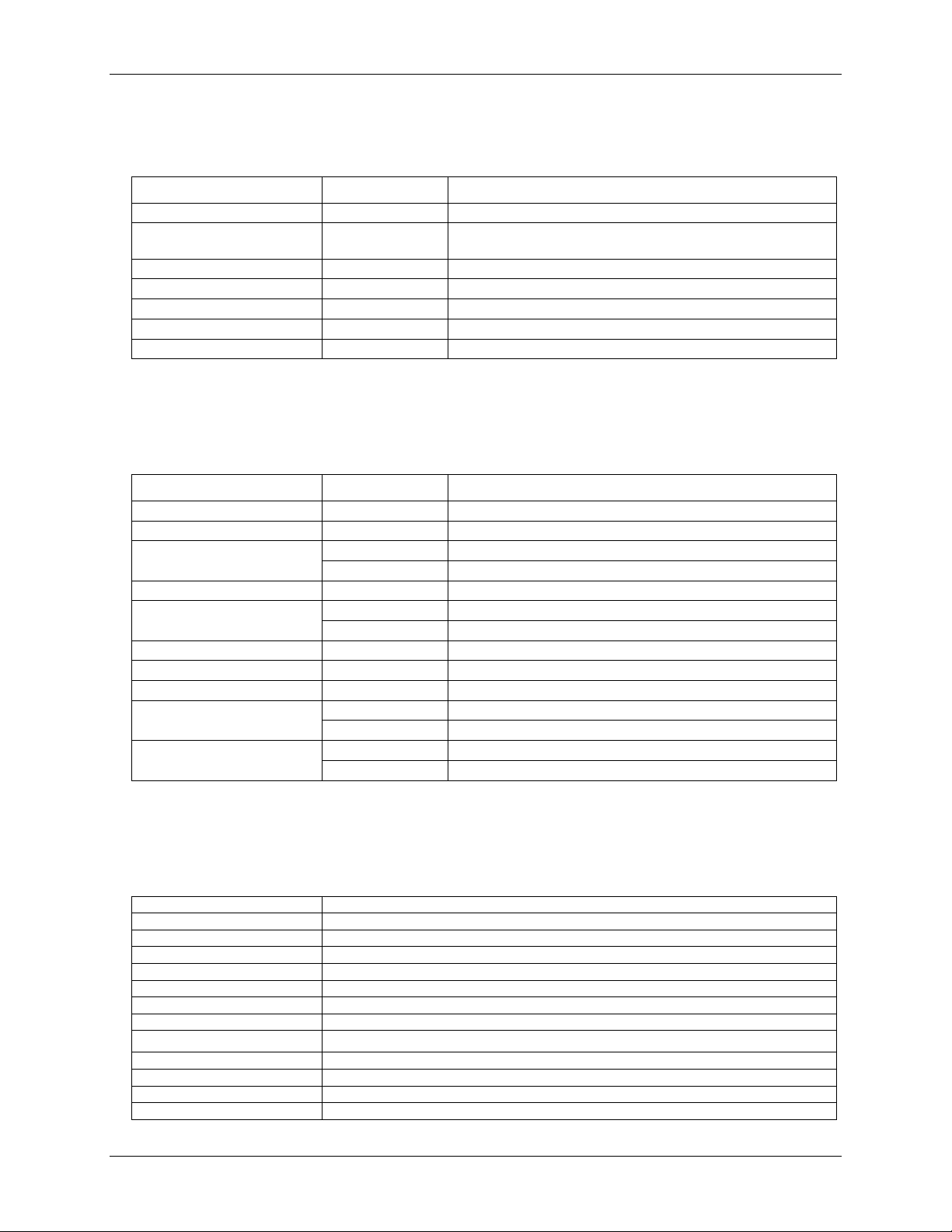
OM-USB-1408FS User's Guide Specifications
Parameter
Conditions
Specification
Trigger source (Note 7)
External digital
TRIG_IN
Trigger mode
Software
selectable
Edge sensitive: user configurable for CMOS compatible rising or
falling edge.
Trigger latency
10 µs max
Trigger pulse width
1 µs min
Input high voltage
4.0 V min, 5.5 V absolute max
Input low voltage
1.0 V max, –0.5 V absolute min
Input leakage current
±1.0 µA
Parameter
Conditions
Specification
Pin name
SYNC
Pin type
Bidirectional
Software selectable direction
Output (default)
Outputs internal A/D pacer clock.
Input
Receives A/D pacer clock from external source.
Input clock rate
48 KHz, maximum
Clock pulse width
Input mode
1 µs min
Output mode
5 µs min
Input leakage current
Input mode
±1.0 µA
Input high voltage
4.0 V min, 5.5 V absolute max
Input low voltage
1.0 V max, –0.5 V absolute min
Output high voltage (Note 8)
IOH = –2.5 mA
3.3 V min
No load
3.8 V min
Output low voltage (Note 8)
IOL = 2.5 mA
1.1 V max
No load
0.6 V max
Pin name (Note 9)
CTR
Counter type
Event counter
Number of channels
1
Input type
TTL, rising edge triggered
Input source
CTR screw terminal
Resolution
32 bits
Schmidt trigger hysteresis
20 mV to 100 mV
Input leakage current
±1 µA
Maximum input frequency
1 MHz
High pulse width
500 ns min
Low pulse width
500 ns min
Input high voltage
4.0 V min, 5.5 V absolute max
Input low voltage
1.0 V max, –0.5 V absolute min
External trigger
Table 10. Digital trigger specifications
Note 7: TRIG_IN is a Schmitt trigger input protected with a 1.5 kilohm (kΩ) series resistor.
External clock input/output
Table 11. External clock I/O specifications
Note 8: SYNC is a Schmitt trigger input and is over-current protected with a 200 Ω series resistor.
Counter section
Note 9: CTR is a Schmitt trigger input protected with a 1.5K Ω series resistor.
Table 12. Counter specifications
25
Page 26
OM-USB-1408FS User's Guide Specifications
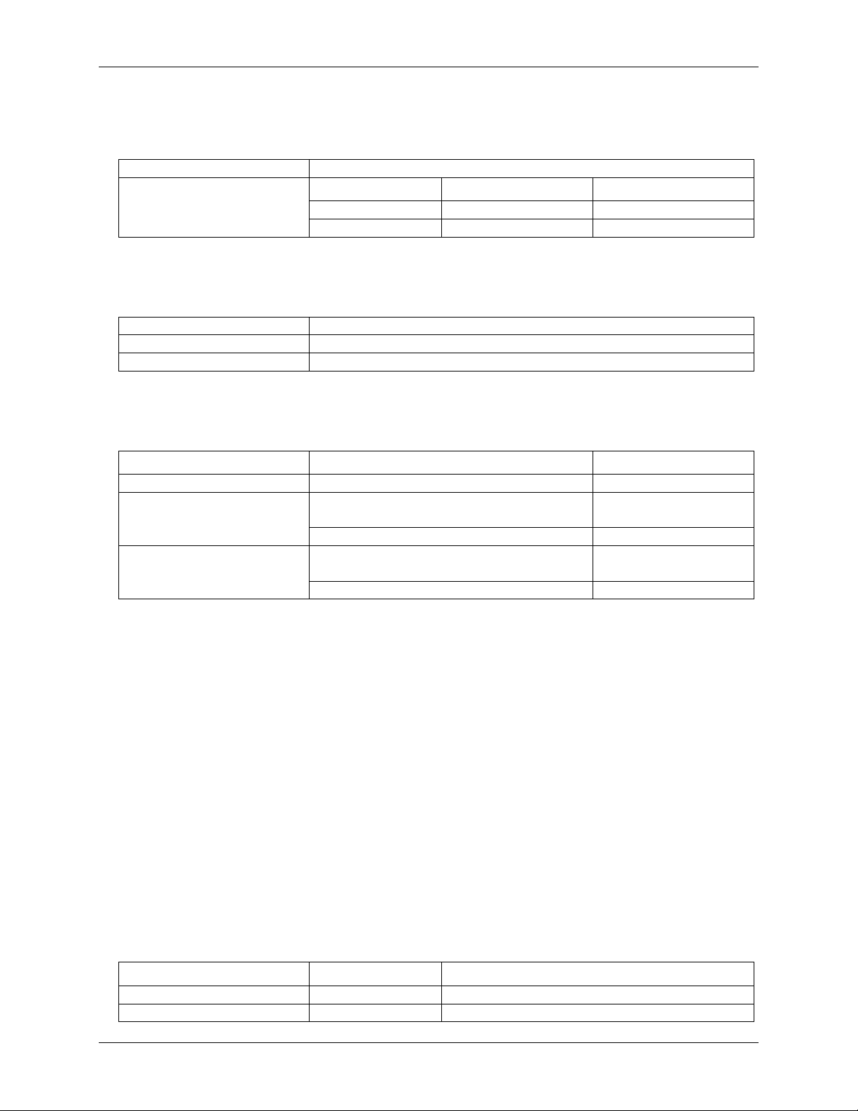
EEPROM
1,024 bytes
EEPROM Configuration
Address Range
Access
Description
0x000-0x1FF
Read/write
512 bytes user area
0x200-0x3FF
Read/write with unlock
512 bytes calibration data
Type
High performance 8-bit RISC microcontroller
Program memory
16,384 words
Data memory
2,048 bytes
Parameter
Conditions
Specification
Supply current (Note 10)
80 mA
+5V USB power available
(Note 11)
Connected to self-powered hub
Connected to externally-powered root port hub
4.5 V min, 5.25 V max
Connected to bus-powered hub
4.1 V min, 5.25 V max
Output current (Note 12)
Connected to self-powered hub
Connected to externally-powered root port hub
420 mA max
Connected to bus-powered hub
20 mA max
Parameter
Conditions
Specification
Device type
USB 2.0 full speed
Device compatibility
USB 1.1, USB 2.0
Non-volatile memory
Table 13. Non-volatile memory specifications
Microcontroller
Table 14. Microcontroller specifications
Power
Table 15. Power specifications
Note 10: This is the total current requirement for the OM-USB-1408FS which includes up to 10 mA for
Note 11: Self-powered hub refers to a USB hub with an external power supply. Self-powered hubs allow
Note 12: Output current refers to the total amount of current that can be sourced from the USB +5 V,
General
the status LED.
a connected USB device to draw up to 500 mA.
Root port hubs reside in the PC’s USB host controller. The USB port(s) on your PC are root port
hubs. All externally powered root port hubs (desktop PCs) provide up to 500 mA of current for
a USB device. Battery-powered root port hubs provide 100 mA or 500 mA, depending upon the
manufacturer. A laptop PC that is not connected to an external power adapter is an example of a
battery-powered root port hub.
Bus powered hubs receive power from a self-powered or root port hub. In this case the
maximum current available from the USB +5 V is 100 mA. The minimum USB +5 V voltage
level can be as low as 4.1 V.
analog outputs and digital outputs.
Table 16. General specifications
26
Page 27
OM-USB-1408FS User's Guide Specifications
Operating temperature range
0 to 70 °C
Storage temperature range
–40 to 70 °C
Humidity
0 to 90% non-condensing
Dimensions
79 millimeters (mm) long x 82 mm wide x 25 mm high
USB cable length
3 meters max
User connection length
3 meters max
Connector type
Screw terminal
Wire gauge range
16 AWG to 30 AWG
Pin
Signal Name
Pin
Signal Name
1
CH0 IN HI
21
Port A0
2
CH0 IN LO
22
Port A1
3
AGND
23
Port A2
4
CH1 IN HI
24
Port A3
5
CH1 IN LO
25
Port A4
6
AGND
26
Port A5
7
CH2 IN HI
27
Port A6
8
CH2 IN LO
28
Port A7
9
AGND
29
GND
10
CH3 IN HI
30
PC+5V
11
CH3 IN LO
31
GND
12
AGND
32
Port B0
13
D/A OUT 0
33
Port B1
14
D/A OUT 1
34
Port B2
15
AGND
35
Port B3
16
+2.5VREF
36
Port B4
17
GND
37
Port B5
18
TRIG_IN
38
Port B6
19
SYNC
39
Port B7
20
CTR
40
GND
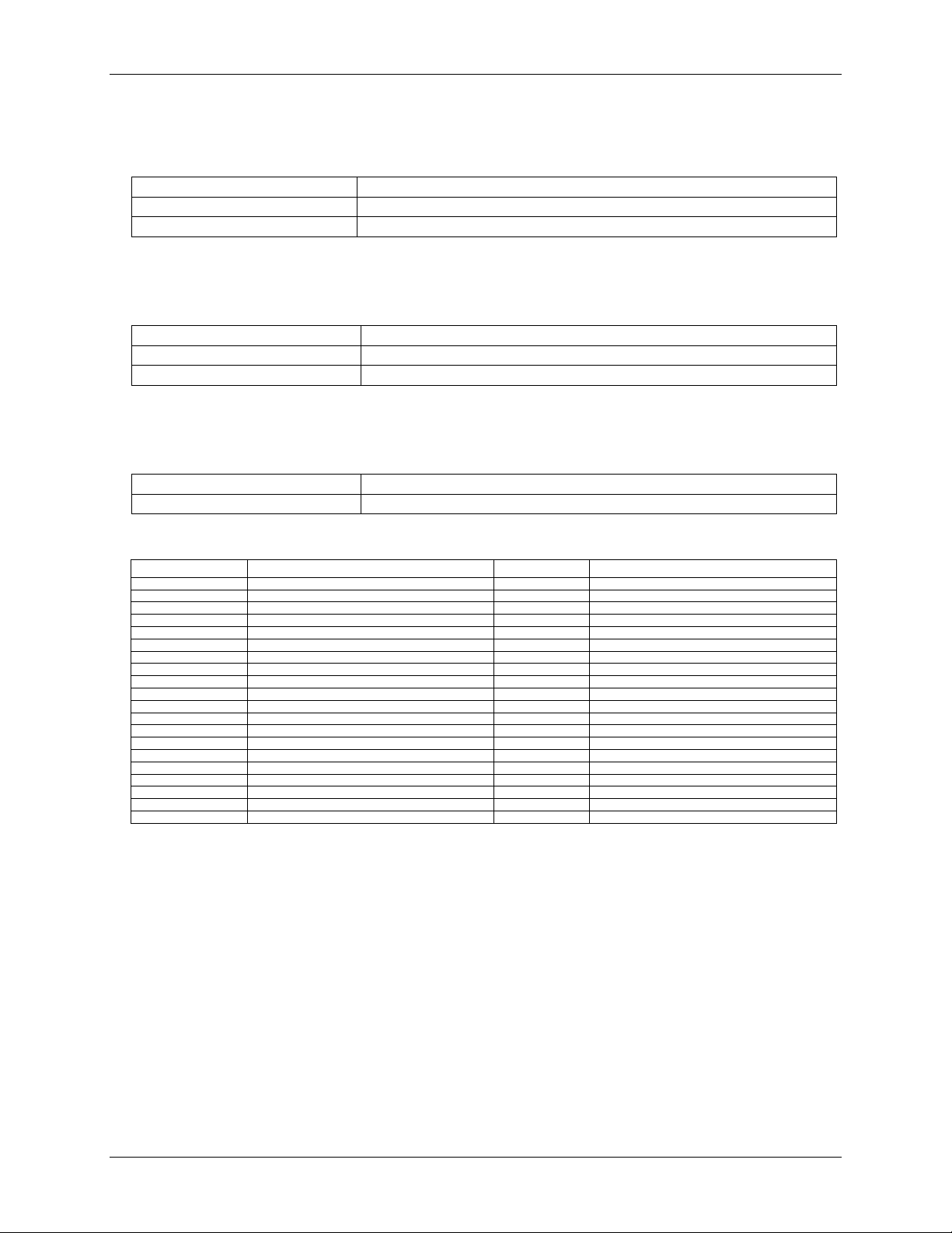
Environmental
Table 17. Environmental specifications
Mechanical
Table 18. Mechanical specifications
Main connector and pin out
Table 19. Main connector specifications
4-channel differential mode
27
Page 28
OM-USB-1408FS User's Guide Specifications
Pin
Signal Name
Pin
Signal Name
1
CH0 IN
21
Port A0
2
CH1 IN
22
Port A1
3
AGND
23
Port A2
4
CH2 IN
24
Port A3
5
CH3 IN
25
Port A4
6
AGND
26
Port A5
7
CH4 IN
27
Port A6
8
CH5 IN
28
Port A7
9
AGND
29
GND
10
CH6 IN
30
PC+5V
11
CH7 IN
31
GND
12
AGND
32
Port B0
13
D/A OUT 0
33
Port B1
14
D/A OUT 1
34
Port B2
15
AGND
35
Port B3
16
+2.5VREF
36
Port B4
17
GND
37
Port B5
18
TRIG_IN
38
Port B6
19
SYNC
39
Port B7
20
CTR
40
GND
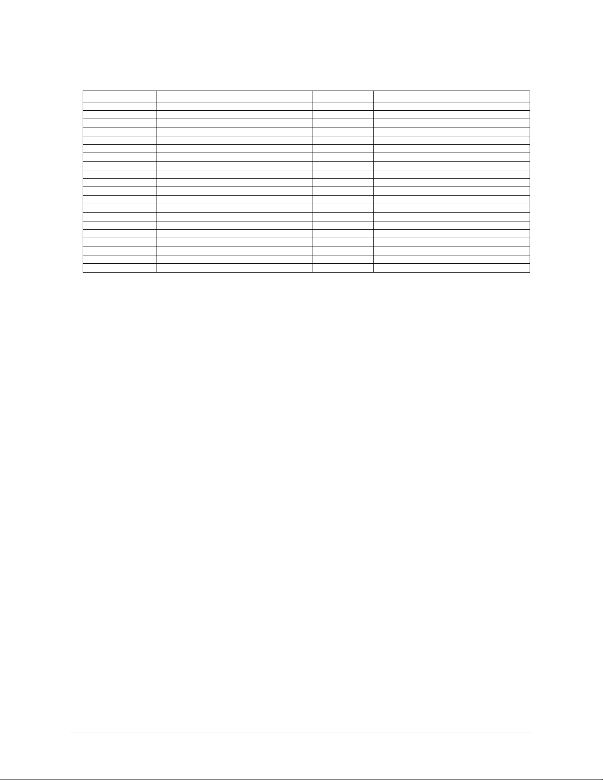
8-channel single-ended mode
28
Page 29
Page 30

M4903 / 0111
 Loading...