

Page 1
Extended Warranty
Program
SM
®
User’s Guide
Shop online at
omega.com
®
e-mail: [email protected]
For latest product manuals:
omegamanual.info
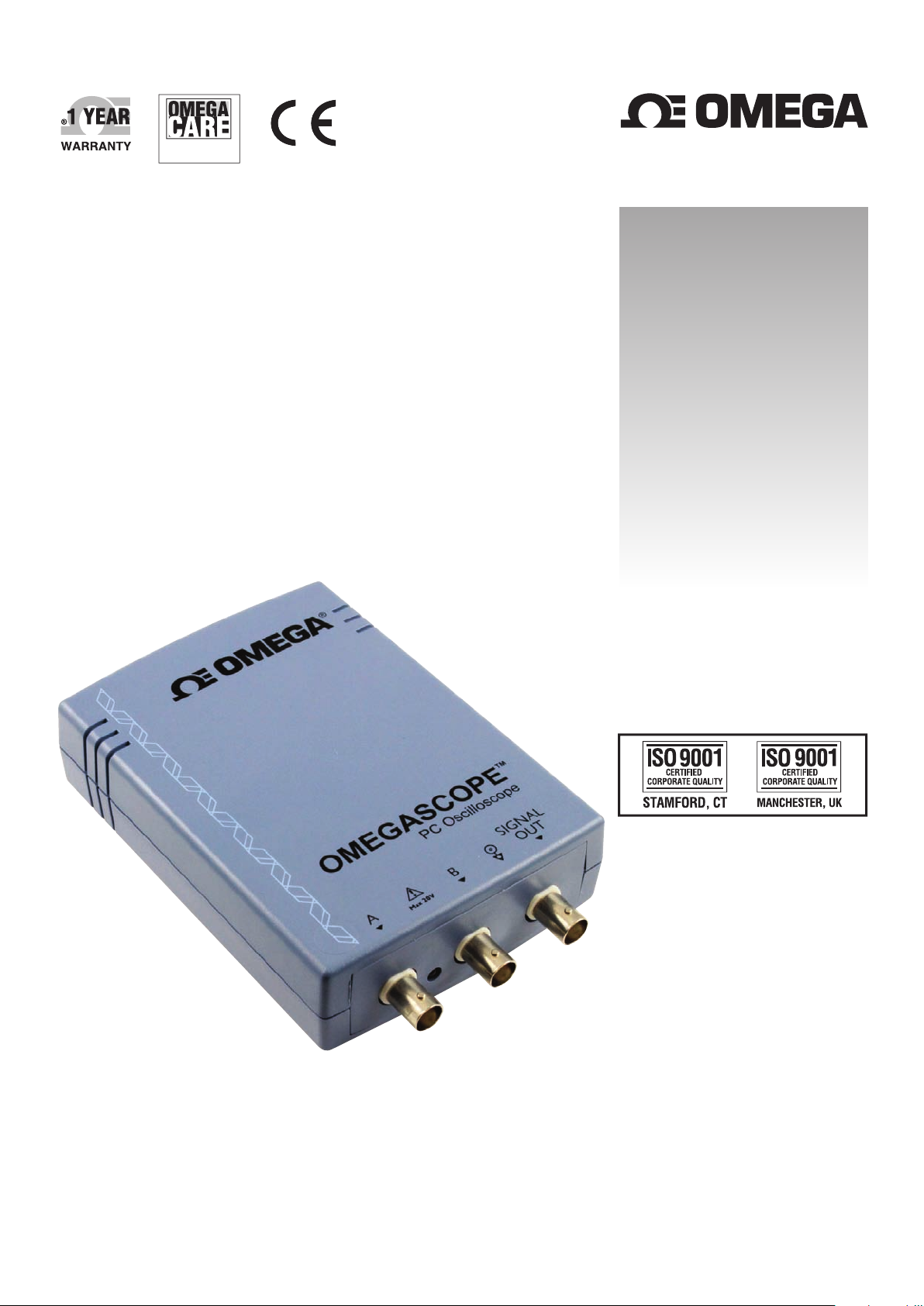
OMEGASCOPE™
OMSP-2000 SERIES
PC Oscilloscopes
Page 2

®
OMEGAnet®Online Service Internet e-mail
omega.com [email protected]
Servicing North America:
U.S.A.: Omega Engineering, Inc., One Omega Drive, P.O. Box 4047
ISO 9001 Certified Stamford, CT 06907-0047 USA
Canada: 976 Bergar
Laval (Quebec), H7L 5A1 Canada
Toll-Free: 1-800-826-6342 TEL: (514) 856-6928
FAX: (514) 856-6886 e-mail: [email protected]
For immediate technical or application assistance:
U.S.A. and Canada: Sales Service: 1-800-826-6342/1-800-TC-OMEGA
Customer Service: 1-800-622-2378/1-800-622-BEST
Engineering Service: 1-800-872-9436/1-800-USA-WHEN
Mexico/ En Español: 001 (203) 359-7803 FAX: 001 (203) 359-7807
Latin America [email protected] e-mail: [email protected]
®
®
®
Servicing Europe:
Benelux: Managed by the United Kingdom Office
Czech Republic: Frystatska 184
733 01 Karviná, Czech Republic
Toll-Free: 0800-1-66342 TEL: +420-59-6311899
FAX: +420-59-6311114 e-mail: [email protected]
France: Managed by the United Kingdom Office
Toll-Free: 0800 466 342 TEL: +33 (0) 161 37 29 00
FAX: +33 (0) 130 57 54 27 e-mail: [email protected]
Germany/Austria: Daimlerstrasse 26
D-75392 Deckenpfronn, Germany
Toll-Free: 0800 6397678 TEL: +49 (0) 7056 9398-0
FAX: +49 (0) 7056 9398-29 e-mail: [email protected]
United Kingdom: OMEGA Engineering Ltd.
ISO 9001 Certified One Omega Drive, River Bend Technology Centre, Northbank
Irlam, Manchester M44 5BD United Kingdom
Toll-Free: 0800-488-488 TEL: +44 (0) 161 777-6611
FAX: +44 (0) 161 777-6622 e-mail: [email protected]
It is the policy of OMEGA Engineering, Inc. to comply with all worldwide safety and EMC/EMI
regulations that apply. OMEGA is constantly pursuing certification of its products to the European New
Approach Directives. OMEGA will add the CE mark to every appropriate device upon certification.
The information contained in this document is believed to be correct, but OMEGA accepts no liability for any
errors it contains, and reserves the right to alter specifications without notice.
WARNING: These products are not designed for use in, and should not be used for, human applications.
Page 3

Contents
ContentsI
....................................................................................................................................11 Welcome
....................................................................................................................................22 Introduction
1 Using this guide
2 Safety symbols
3 Safety warning
4 FCC notice
5 CE notice
6 Trademarks
7 Company details
........................................................................................................................................2
........................................................................................................................................2
........................................................................................................................................3
........................................................................................................................................3
........................................................................................................................................3
........................................................................................................................................4
........................................................................................................................................4
....................................................................................................................................53 Product information
1 What do I get?
2 System requirements
3 Installation instructions
4 Connections
1 Connector diagrams
2 Signal inputs
3 Signal Out connector
4 USB port
5 Specifications
........................................................................................................................................5
........................................................................................................................................5
........................................................................................................................................6
........................................................................................................................................7
........................................................................................................................................9
....................................................................................................................................104 Glossary
......................................................................................................................................................................7
......................................................................................................................................................................8
......................................................................................................................................................................8
......................................................................................................................................................................8
Index
....................................................................................................................................12
M5060
Page 4
OMSP-2000 Series User's Guide 1
The OMSP-2000 Series PC Oscilloscopes are
compact units designed to replace traditional benchtop oscilloscopes costing many times the price.
1 Welcome
Here are some of the benefits provided by your new PC Oscilloscope:
Portability: Take the unit with you and plug it in to any Windows PC.
Performance: Fast sampling from 100 MS/s to 200 MS/s, probe-tip bandwidth
from 10 MHz to 25 MHz and fast USB 2.0 interface. See Specifications for the
details of each scope model.
Flexibility: Use it as an oscilloscope, spectrum analyser, data logger or high-speed
data acquisition interface.
Long-term support: Software upgrades are available to download from our
website. You can also call our specialists for technical support. You can continue
to use both of these services free of charge for the lifetime of the product.
9
Value for money: Buying an OMSP-2000 Series PC Oscilloscope means that you
don't have to pay twice for all the features that you already have in your PC. The
OMSP-2000 Series oscilloscope contains the special hardware you need and nothing
more.
Convenience: The software makes full use of the display, storage, user interface
and networking built in to your PC.
M5060
Page 5

2 Introduction
This symbol indicates that a safety hazard exists on the indicated
connections if correct precautions are not taken. Read all safety
documentation associated with the product before using it.
This symbol indicates that the outer shells of the indicated BNC
connectors are all at the same potential (shorted together). You
must therefore take necessary precautions to avoid applying a
potential across the return connections of the indicated BNC
terminals. Such a potential could cause a large current to flow,
resulting in damage to the product or the connected equipment, or
both.
Introduction2
2.1
2.2
Using this guide
In this guide you will see symbols like this: This is the cross-reference symbol,
and it indicates the number of a page on which you can find more information about a
topic.
The abbreviation MS/s is used in this guide to mean megasamples per second.
2
Safety symbols
The following symbols appear on the top of the OMSP-2000 Series PC Oscilloscopes.
Symbol 1: Warning triangle
Symbol 2: Equipotential
M5060
Page 6

OMSP-2000 Series User's Guide 3
2.3
Safety warning
We strongly recommend that you read the general safety information below before
using your oscilloscope for the first time. Safety protection built in to equipment may
cease to function if the equipment is used incorrectly. This could cause damage to
your computer, or lead to injury to yourself and others.
Maximum input range
The OMSP-2000 Series PC Oscilloscopes are designed to measure voltages in the
range -20 V to +20 V. The Ch A and Ch B inputs are protected to ±100 V. Contact
with voltages outside the protection range may cause permanent damage to the unit.
Mains voltages
These products are not designed for use with mains (line power) voltages. To measure
mains, use a differential isolating probe specifically designed for high voltages.
Safety grounding
The OMSP-2000 Series PC Oscilloscopes connect directly to the ground of a computer
through the USB cable provided to minimise interference.
As with most oscilloscopes, avoid connecting the ground input to any potential other
than ground. If in doubt, use a meter to check that there is no significant AC or DC
voltage between the ground input of the oscilloscope and the point to which you
intend to connect it. Failure to check may cause damage to your computer or injury to
yourself and others.
2.4
2.5
The product does not have a protective safety ground.
Repairs
The oscilloscope contains no user-serviceable parts. Repair or calibration of the
oscilloscope requires specialised test equipment and must be performed by the
factory.
FCC notice
This equipment has been tested to meet CFR47 (2006) Part 15 of the FCC limits
for Class A equipment. These limits are designed to provide reasonable protection
against harmful interference when the equipment is operated in a commercial
environment. This equipment generates, uses, and can radiate radio frequency energy
and, if not installed and used in accordance with the instruction manual, may cause
harmful interference to radio communications. Operation of this equipment in a
residential area is likely to cause harmful interference in which case the user will be
required to correct the interference at his or her own expense.
The OMSP-2000 Series PC Oscilloscopes were successfully tested to the standard.
For safety and maintenance information see the safety warning .
3
CE notice
The OMSP-2000 Series PC Oscilloscopes meet the intent of the EMC directive
89/336/EEC and have been designed to EN61326-1 (2006) Class A Emissions
and Immunity standard.
The OMSP-2000 Series PC Oscilloscopes also meet the intent of the Low Voltage
Directive and have been designed to meet the BS EN 61010-1:2001 IEC 610101:2001 (Safety requirements for electrical equipment for measurement, control and
laboratory use) standard.
M5060
Page 7

Introduction4
Address:
Omega Engineering, Inc.
One Omega Drive
P.O. Box 4047
Stamford, CT 06907
USA
Phone:
203-359-1660
Fax:
203-359-7700
Email:
Technical Support:
Sales:
Web site:
www.omega.com
2.6
2.7
Trademarks
Windows, Excel and Visual Basic are registered trademarks or trademarks of
Microsoft Corporation in the USA and other countries. Delphi is a registered
trademark of Borland Software Corporation. Agilent VEE is a registered trademark of
Agilent Technologies, Inc. LabView is a registered trademark of National Instruments
Corporation.
OMEGASCOPE™ is a trademark of Omega Engineering, Inc.
Company details
M5060
Page 8
OMSP-2000 Series User's Guide 5
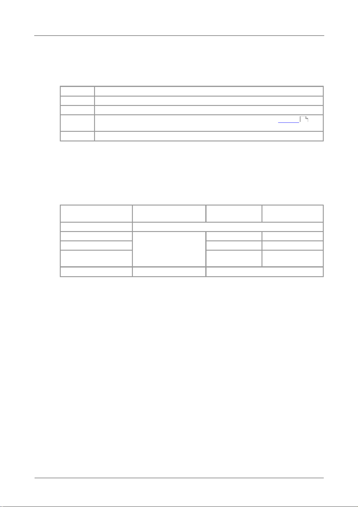
Quantity
Description
1
PC Oscilloscope
1
USB cable, for connection to the USB 1.1 or USB 2.0 port on your PC
1
Software and Reference CD, with OMEGASCOPE™ software, drivers ,
and example programs
1
USB Oscilloscope Installation Guide
Item
Absolute
minimum
Recommended
minimum
Recommended
full specification
Operating system
Windows XP SP2, Windows Vista or Windows 7
Processor
As required
by Windows
300 MHz
1 GHz
Memory
256 MB
512 MB
Free disk space
(Note 1)
1 GB
2 GB
Ports
USB 1.1 compliant port
USB 2.0 compliant port
3 Product information
3.1
3.2
What do I get?
Your OMSP-2000 Series PC Oscilloscope kit contains the following items:
10
System requirements
To ensure that your OMSP-2000 Series PC Oscilloscope operates correctly, you must
have a computer with at least the minimum system requirements to run one of the
supported operating systems, as shown in the following table. The performance of the
software will increase with more powerful PCs, including those with multi-core
processors.
Note 1: The OMEGASCOPE™ software does not use all the disk space specified in the
table. The free space is required to make Windows run efficiently.
M5060
Page 9

Product information6
IMPORTANT
Do not connect your OMSP-2000 Series PC Oscilloscope to the PC before you
have installed the OMEGASCOPE™ software.
If you do, Windows might not recognise the scope device correctly.
3.3
Installation instructions
Procedure
Follow the instructions in the Installation Guide included with your product
package.
Connect your PC Oscilloscope to the PC using the USB cable supplied.
Checking the installation
Once you have installed the software and connected the PC Oscilloscope to the PC,
start the OMEGASCOPE™ software. The software should now display any signal
connected to the scope inputs. If a probe is connected to your oscilloscope, you
should see a small 50 or 60 hertz noise signal in the oscilloscope window when you
touch the probe tip with your finger.
Moving your OMEGASCOPE™ PC Oscilloscope to another USB port
Windows XP SP2
When you first installed the OMSP-2000 Series PC Oscilloscope by plugging it into a
11
USB port, Windows associated the driver with that port. If you later move the
oscilloscope to a different USB port, Windows will display the "New Hardware Found
Wizard" again. When this occurs, just click "Next" in the wizard to repeat the
installation. If Windows gives a warning about Windows Logo Testing, click "Continue
Anyway". As all the software you need is already installed on your computer, there is
no need to insert the OMEGASCOPE™ CD again.
Windows Vista and Windows 7
The process is automatic. When you move the device from one port to another,
Windows displays an "Installing device driver software" message and then a "OMSP2000 Series PC Oscilloscope" message. The PC Oscilloscope is then ready for use.
M5060
Page 10
OMSP-2000 Series User's Guide 7
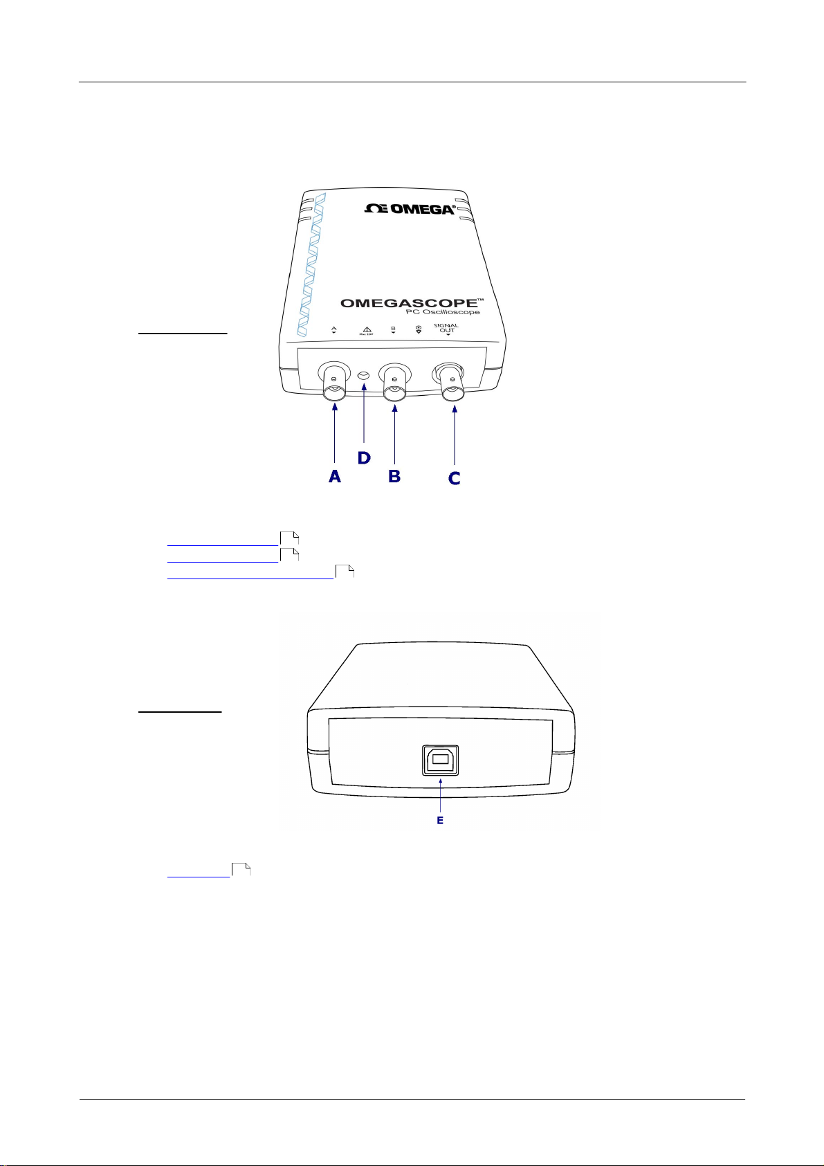
Front panel
OMSP-2204
OMSP-2205
Rear panel
OMSP-2204
OMSP-2205
3.4
3.4.1
Connections
Connector diagrams
Connector diagrams
A. Input channel A
B. Input channel B
C. Signal generator output
8
8
8
D. LED: shows when the oscilloscope is sampling data
E. USB port
8
M5060
Page 11

Product information8
3.4.2
3.4.3
3.4.4
Signal inputs
The OMSP-2000 Series PC Oscilloscopes have BNC oscilloscope connectors. The inputs
have an impedance of 1 M , so they are compatible with all standard scope probes
including x10 attenuated types.
Signal Out connector
The SIGNAL OUT connector on the front panel carries the output of the oscilloscope's
built-in signal generator, which can generate a number of built-in waveforms as well
as arbitrary waveforms from a user-defined table of data.
Instructions for use
Refer to the OMEGASCOPE™ Software User's Guide for information on how to
configure the signal generator.
Signal generator output specifications
Refer to the Specifications table .
9
USB port
Connect the oscilloscope's USB port to your PC's USB 2.0 port using the USB cable
supplied. You can also connect it to a USB 1.1 port, but in this configuration the
oscilloscope will not operate at full performance.
M5060
Page 12
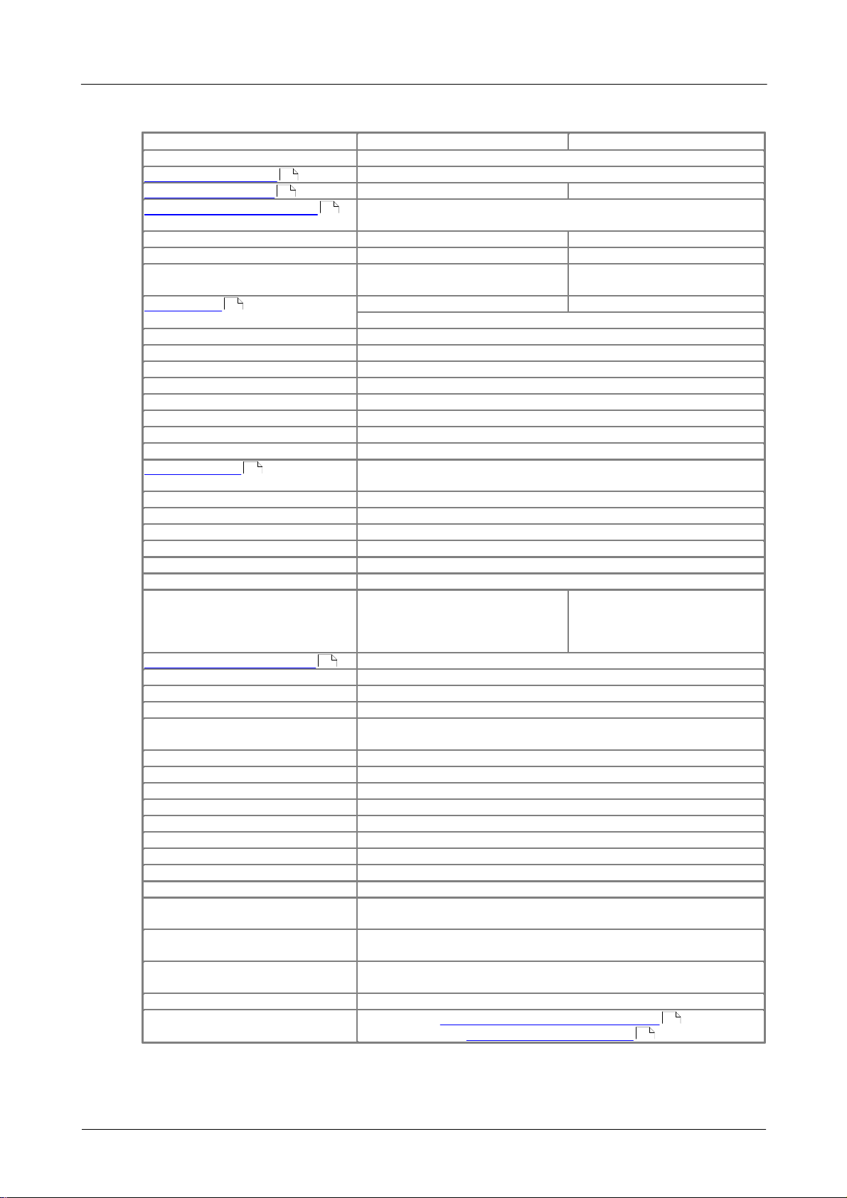
OMSP-2000 Series User's Guide 9
Variant
OMS-2204
OMSP-2205
Number of channels
2
Vertical resolution
8 bits
Analog bandwidth
10 MHz
25 MHz
Maximum sampling rate
(real time)
One channel in use
100 MS/s
200 MS/s
Two channels in use
50 MS/s
100 MS/s
Maximum sampling rate
(repetitive signals)
2 GS/s
4 GS/s
Buffer size
8,000 samples
16,000 samples
If two channels in use, buffer shared between channels.
Timebase
Ranges
2 ns/div (ETS) or 50 ns/div (real-time) to 200 s/div
Accuracy
±100 ppm
Inputs
Connectors
BNC female
Input impedance
1 MΩ
Input capacitance
20 pF or less
Coupling
AC or DC, software-controlled
Voltage ranges
±50 mV, ±100 mV, ±200 mV, ±500 mV,
±1 V, ±2 V, ±5 V, ±10 V, ±20 V
Accuracy
3%
Noise
1 LSB on ±1 V range
Dynamic range
48 dB
Overload protection
±100 V on single input
Trigger
Source
Ch A or Ch B
Modes
Rising edge,
falling edge
Rising edge, falling edge,
hysteresis, pulse width,
interval, dropout,
windowed, logic
Signal generator output
Standard waveforms
Sine, square, triangle, ramp (up/down)
Arbitrary waveform buffer
4,096 samples
DAC clock frequency
2 MHz
Maximum signal frequency using
standard waveforms
100 kHz
Output impedance
600 Ω
Resolution
8 bits
Amplitude
±250 mV to ±2 V with ±1 V offset
Operating environment
Temperature range
0 °C to 45 °C (20 °C to 30 °C for quoted accuracy)
Humidity
5% to 80% non-condensing
Storage environment
Temperature range
-20 °C to +60 °C
Humidity
5% to 95% non-condensing
PC connection
Designed for USB 2.0
Will work with USB 1.1 at reduced performance
Power supply
4.60 V to 5.25 V @ 500 mA max.
Obtained from USB port
Dimensions
100 x 150 x 37 mm
(3.9 x 5.9 x 1.5 in)
Weight
210 g (7.4 oz)
Compliance
European EMC and LVD standards
FCC Rules Part 15 Class A
3.5
Specifications
11
10
10
10
11
8
3
3
M5060
Page 13

4 Glossary
Analog bandwidth—The frequency at which the measured signal amplitude is
3 decibels below the true signal amplitude.
Block mode—A fast data collection mode. The OMEGASCOPE™ software puts the
oscilloscope into this mode to achieve the fastest possible sampling rates. The
oscilloscope collects data as fast as possible and then stops to transfer the data to the
PC. During data transfer to the PC in block mode, the oscilloscope cannot sample data
from its inputs.
Buffer size—The size of the oscilloscope's buffer memory, measured in samples. The
buffer allows the oscilloscope to sample data faster than it can transfer it to the
computer.
Coupling mode—To switch from AC coupling to DC coupling, or vice versa, select AC
or DC from the control on the OMEGASCOPE™ toolbar. The AC setting filters out very
low-frequency components of the input signal, including DC, and is suitable for
viewing small AC signals superimposed on a DC or slowly changing offset. In this
mode you can measure the peak-to-peak amplitude of an AC signal but not its
absolute value. Use the DC setting for measuring the absolute value of a signal.
Glossary10
Device Manager—Device Manager is a Windows program that displays the current
hardware configuration of your computer. On Windows XP or Vista, right-click on 'My
Computer,' choose 'Properties', then click the 'Hardware' tab and the 'Device Manager'
button.
Driver—A program that controls a piece of hardware. The driver for the OMSP-2000
Series PC Oscilloscopes is supplied in the form of a 32-bit Windows DLL, ps2000.dll.
This is used by the OMEGASCOPE™ software to control the oscilloscope.
ETS—Equivalent Time Sampling. Constructs a picture of a repetitive signal by
accumulating information over many similar wave cycles. This allows the oscilloscope
to create a composite cycle that has more samples, and therefore better time
resolution, than a single cycle. ETS cannot be used for one-shot signals.
Maximum sampling rate—A figure indicating the maximum number of samples the
oscilloscope can acquire per second. The higher the sampling rate of the oscilloscope,
the more accurate the representation of the high-frequency details in a fast signal.
"MS/s" is used in this manual an abbreviation for "millions of samples per second".
OMEGASCOPE™ software—A software program that accompanies all OMSP-2000
Series PC Oscilloscopes. It turns your PC into an oscilloscope, spectrum analyser, and
meter display.
Oversampling—A technique for reducing noise in sampled signals. Measurements
are taken more frequently than the requested sample rate, and then merged to
produce the required number of samples. If, as is usually the case, the signal
contains a small amount of noise, this technique can increase the effective vertical
resolution of the oscilloscope.
11
PC Oscilloscope—A virtual instrument formed by connecting an OMSP-2000 Series
oscilloscope to a computer running the OMEGASCOPE™ software.
M5060
Page 14

OMSP-2000 Series User's Guide 11
Signal generator—Generates a waveform and outputs it on the BNC socket marked
Signal Out. This output can be used to drive a test signal through a BNC cable into an
external circuit or into one of the oscilloscope's input channels. The OMEGASCOPE™
software allows the generator to output standard waveforms, such as sine and square
waves, or arbitrary waveforms defined by the user.
Streaming mode—A data collection mode in which the oscilloscope samples data and
returns it to the computer in a continuous stream. This mode allows the capture of
more data than will fit in the oscilloscope's memory buffer, at sampling rates up to
13.3 million samples per second. The OMEGASCOPE™ program selects this mode for
long timebases to enable the capture of very long sets of data.
Timebase—A timer that controls the speed at which the scope device captures data.
At slow timebases this process is visible as OMEGASCOPE™ draws the trace across the
scope view from left to right, but at fast timebases OMEGASCOPE™ draws the whole
trace in a single operation. The timebase is measured in units of time (such as
seconds) per division. There are ten divisions across the scope view, so the total time
across the width of the view is ten times the "per division" setting.
USB 1.1—Universal Serial Bus (Full Speed). This is a standard port used to connect
external devices to PCs. A typical USB 1.1 port supports a data transfer rate of 12
megabits per second, so is much faster than an RS-232 or 'COM' port.
USB 2.0—Universal Serial Bus (High Speed). This is a standard port used to connect
external devices to PCs. A typical USB 2.0 port supports a data transfer rate 40 times
faster than USB 1.1 when used with a USB 2.0 device, but can also be used with USB
1.1 devices.
Vertical resolution—A value, in bits, indicating the precision with which the
oscilloscope converts input voltages to digital values. Oversampling (see above) can
improve the effective vertical resolution.
Voltage range—The range of input voltages that the oscilloscope can measure. For
example, a voltage range of ±100 mV means that the oscilloscope can measure
voltages between -100 mV and +100 mV. Input voltages outside this range will not be
measured correctly, but will not damage the instrument as long as they remain within
the protection limits of ±100 V.
M5060
Page 15

Index12
Index
A
Accuracy
timebase 9
voltage 9
Analog bandwidth 9
Arbitrary waveform generator 8
B
Bandwidth (analog) 9
BNC connector 8
Buffers
size 9
C
Calibration 3
CE notice 3
Company information 4
Compliance 9
Connections 7
Contact details 4
Low Voltage Directive 3
M
Mains voltages 3
N
Noise 9
O
OMEGASCOPE™ software 6
OMSP-2000 Series 1
Operating environment 9
Operating system 5
Oscilloscope probe 8
Outputs 9
Overload protection 9
P
PC connection 9
Power supply 9
Processor 5
R
D
Dimensions 9
Disk space 5
Dynamic range 9
E
EMC Directive 3
F
FCC notice 3
G
Grounding 3
I
Input range, maximum 3, 9
Inputs 9
Installation 6
L
LED 7
Repairs 3
Resolution, vertical 9
S
Safety
symbols 2
warning 3
Sampling rate 9
Scope probe 8
Signal generator 8, 9
output 8
Signal Out connector 8
Specifications 9
Storage environment 9
System memory 5
System requirements 5
T
Technical support 4
Test equipment 3
Trademarks 4
Trigger
bandwidth 9
modes 9
M5060
Page 16

OMSP-2000 Series User's Guide 13
Trigger
source 9
U
USB 5
changing ports 6
USB port 8
V
Vertical resolution 9
Voltage ranges 9
W
Weight 9
Windows, Microsoft 5
M5060
Page 17

14
M5060
Page 18

WARRANTY/DISCLAIMER
OMEGA ENGINEERING, INC. warrants this unit to be free of defects in materials and workmanship for a
period of 13 months from date of purchase. OMEGA’s WARRANTY adds an additional one (1) month
grace period to the normal one (1) year product warranty to cover handling and shipping time. This
ensures that OMEGA’s customers receive maximum coverage on each product.
If the unit malfunctions, it must be returned to the factory for evaluation. OMEGA’s Customer Service
Department will issue an Authorized Return (AR) number immediately upon phone or written request.
Upon examination by OMEGA, if the unit is found to be defective, it will be repaired or replaced at no
charge. OMEGA’s WARRANTY does not apply to defects resulting from any action of the purchaser,
including but not limited to mishandling, improper interfacing, operation outside of design limits,
improper repair, or unauthorized modification. This WARRANTY is VOID if the unit shows evidence of
having been tampered with or shows evidence of having been damaged as a result of excessive corrosion;
or current, heat, moisture or vibration; improper specification; misapplication; misuse or other operating
conditions outside of OMEGA’s control. Components in which wear is not warranted, include but are not
limited to contact points, fuses, and triacs.
OMEGA is pleased to offer suggestions on the use of its various products. However,
OMEGA neither assumes responsibility for any omissions or errors nor assumes liability for any
damages that result from the use of its products in accordance with information provided by
OMEGA, either verbal or written. OMEGA warrants only that the parts manufactured by it will be
as specified and free of defects. OMEGA MAKES NO OTHER WARRANTIES OR
REPRESENTATIONS OF ANY KIND WHATSOEVER, EXPRESS OR IMPLIED, EXCEPT THAT OF TITLE,
AND ALL IMPLIED WARRANTIES INCLUDING ANY WARRANTY OF MERCHANTABILITY AND
FITNESS FOR A PARTICULAR PURPOSE ARE HEREBY DISCLAIMED. LIMITATION OF
LIABILITY: The remedies of purchaser set forth herein are exclusive, and the total liability of
OMEGA with respect to this order, whether based on contract, warranty, negligence,
indemnification, strict liability or otherwise, shall not exceed the purchase price of the
component upon which liability is based. In no event shall OMEGA be liable for
consequential, incidental or special damages.
CONDITIONS: Equipment sold by OMEGA is not intended to be used, nor shall it be used: (1) as a “Basic
Component” under 10 CFR 21 (NRC), used in or with any nuclear installation or activity; or (2) in medical
applications or used on humans. Should any Product(s) be used in or with any nuclear installation or
activity, medical application, used on humans, or misused in any way, OMEGA assumes no responsibility
as set forth in our basic WARRANTY/ DISCLAIMER language, and, additionally, purchaser will indemnify
OMEGA and hold OMEGA harmless from any liability or damage whatsoever arising out of the use of the
Product(s) in such a manner.
RETURN REQUESTS/INQUIRIES
Direct all warranty and repair requests/inquiries to the OMEGA Customer Service Department. BEFORE
RETURNING ANY PRODUCT(S) TO OMEGA, PURCHASER MUST OBTAIN AN AUTHORIZED RETURN
(AR) NUMBER FROM OMEGA’S CUSTOMER SERVICE DEPARTMENT (IN ORDER TO AVOID
PROCESSING DELAYS). The assigned AR number should then be marked on the outside of the return
package and on any correspondence.
The purchaser is responsible for shipping charges, freight, insurance and proper packaging to prevent
breakage in transit.
FOR WARRANTY
following information available BEFORE
contacting OMEGA:
1. Purchase Order number under which the product
was PURCHASED,
2. Model and serial number of the product under
warranty, and
3. Repair instructions and/or specific problems
relative to the product.
OMEGA’s policy is to make running changes, not model changes, whenever an improvement is possible. This affords
our customers the latest in technology and engineering.
OMEGA is a registered trademark of OMEGA ENGINEERING, INC.
© Copyright 2011 OMEGA ENGINEERING, INC. All rights reserved. This document may not be copied, photocopied,
reproduced, translated, or reduced to any electronic medium or machine-readable form, in whole or in part, without the
prior written consent of OMEGA ENGINEERING, INC.
RETURNS, please have the
FOR NON-WARRANTY REPAIRS,
for current repair charges. Have the following
information available BEFORE contacting OMEGA:
1. Purchase Order number to cover the COST
of the repair,
2. Model and serial number of the product, and
3. Repair instructions and/or specific problems
relative to the product.
consult OMEGA
Page 19

Where Do I Find Everything I Need for
Process Measurement and Control?
OMEGA…Of Course!
Shop online at omega.com
sm
TEMPERATURE
䡺⻬
Thermocouple, RTD & Thermistor Probes, Connectors, Panels & Assemblies
䡺⻬
Wire: Thermocouple, RTD & Thermistor
䡺⻬
Calibrators & Ice Point References
䡺⻬
Recorders, Controllers & Process Monitors
䡺⻬
Infrared Pyrometers
PRESSURE, STRAIN AND FORCE
䡺⻬
Transducers & Strain Gages
䡺⻬
Load Cells & Pressure Gages
䡺⻬
Displacement Transducers
䡺⻬
Instrumentation & Accessories
FLOW/LEVEL
䡺⻬
Rotameters, Gas Mass Flowmeters & Flow Computers
䡺⻬
Air Velocity Indicators
䡺⻬
Turbine/Paddlewheel Systems
䡺⻬
Totalizers & Batch Controllers
pH/CONDUCTIVITY
䡺⻬
pH Electrodes, Testers & Accessories
䡺⻬
Benchtop/Laboratory Meters
䡺⻬
Controllers, Calibrators, Simulators & Pumps
䡺⻬
Industrial pH & Conductivity Equipment
DATA ACQUISITION
䡺⻬
Data Acquisition & Engineering Software
䡺⻬
Communications-Based Acquisition Systems
䡺⻬
Plug-in Cards for Apple, IBM & Compatibles
䡺⻬
Data Logging Systems
䡺⻬
Recorders, Printers & Plotters
HEATERS
䡺⻬
Heating Cable
䡺⻬
Cartridge & Strip Heaters
䡺⻬
Immersion & Band Heaters
䡺⻬
Flexible Heaters
䡺⻬
Laboratory Heaters
ENVIRONMENTAL
MONITORING AND CONTROL
䡺⻬
Metering & Control Instrumentation
䡺⻬
Refractometers
䡺⻬
Pumps & Tubing
䡺⻬
Air, Soil & Water Monitors
䡺⻬
Industrial Water & Wastewater Treatment
䡺⻬
pH, Conductivity & Dissolved Oxygen Instruments
M5060/1111
 Loading...