

Page 1
User’s Guide
Shop online at
Includes:
Software and
Users Guide
OM-PL Series
Data Logger Software
Rev _______
omega.com
800-DAS-IEEE (800-327-4333)
© COPYRIGHT 2015 OMEGA ENGINEERING, INC.
OM-PLT2
®
omega.com
e-mail: [email protected]
For latest product manuals:
www.omegamanual.info
SM
OM-PL SERIES
Data Logger Interface Software
Page 2

omega.com [email protected]
Servicing North America:
U.S.A.: Omega Engineering, Inc., One Omega Drive, P.O. Box 4047
Stamford, CT 06907-0047 USA
Toll-Free: 1-800-826-6342 (USA & Canada only)
Customer Service: 1-800-622-2378 (USA & Canada only)
Engineering Service: 1-800-872-9436 (USA & Canada only)
Tel: (203) 359-1660 Fax: (203) 359-7700
e-mail: [email protected]
For Other Locations Visit omega.com/worldwide
The information contained in this document is believed to be correct, but OMEGA accepts no liability for any errors it contains, and reserves
the right to alter specifications without notice.
Page 3

Table Of Contents
Quick Start ................................................................................................................... 4
Overview ...................................................................................................................... 4
Available Loggers ........................................................................................................ 4
Connecting the Logger to Your PC ............................................................................... 5
Setting Up The Logger To Record Data ....................................................................... 6
Custom Interval Setup .................................................................................................. 7
Alarm Setup Window .................................................................................................... 7
Advanced Setup Window ............................................................................................. 8
Checking the Logger Status ......................................................................................... 9
Logger Status Light ...................................................................................................... 9
Checking the Logger Status Using the Software .......................................................... 9
Finishing the Logging Session ................................................................................... 10
Retrieving the Data from the Logger .......................................................................... 10
Automatic Data Retrieval ........................................................................................... 11
Working with the Data Graph ..................................................................................... 12
Using the Zoom Feature ............................................................................................ 13
Data Information Window ........................................................................................... 14
Data Listing ................................................................................................................ 14
Data Summary ........................................................................................................... 15
Alarm Summary ......................................................................................................... 15
Using the Data Filter .................................................................................................. 15
Data Units .................................................................................................................. 16
Hiding and Viewing Channels .................................................................................... 17
Saving and Loading Logger Data ............................................................................... 17
Exporting Logger Data ............................................................................................... 17
Printing Logger Data .................................................................................................. 18
Calibrating the Logger ................................................................................................ 18
Changing The Calibration Password .......................................................................... 19
Setting the Logger's Real Time Clock ........................................................................ 19
Data Security ............................................................................................................. 19
Logger Battery Replacement ...................................................................................... 20
OM-PL Logger Interface Software Specifications ....................................................... 21
OM-PLT2: Internal / External Temperature Logger .................................................... 21
Page 4

Connecting the External Temperature Probe to OM-PLT2 ......................................... 21
OM-PLT2 Bat tery Selection ........................................................................................ 21
OM-PLT2 Specifications ............................................................................................ 22
OM-PLTH: Temperature Humidity Logger .................................................................. 22
OM-PLTH Specifications ............................................................................................ 23
OM-PLTT: Dual External Temperature Logger ........................................................... 23
OM-PLTT Specifications ............................................................................................ 24
OM-PLPT: Pressure Temperature Logger .................................................................. 24
Connecting the Sensors to the OM-PLPT .................................................................. 24
OM-PLPT Specifications ............................................................................................ 25
OM-PLCV: AC Current, AC Voltage Logger ............................................................... 25
Connecting the OM-PLCV to Electrical Equipment ..................................................... 26
Connecting the OM-PLCV to both the Computer and a Voltage Source ..................... 26
OM-PLCV Specifications ............................................................................................ 27
OM-PL420: 4 - 20ma Current Loop Logger ................................................................ 27
Connecting the OM-PL420 to the 4 - 20 ma Loop. ..................................................... 27
OM-PL420 Specifications ........................................................................................... 28
OM-PLTC: Thermocouple Temperature Logger ......................................................... 28
OM-PLTC Logging Setup ........................................................................................... 28
OM-PLTC Safety Precautions .................................................................................... 28
OM-PLTC Thermocouple Temperature Ranges ......................................................... 29
OM-PLTC Specifications ............................................................................................ 29
Page 5

OM-PL Series Data Logger Interface Software Version 2.5x Page 4 /29
Quick Start
Follow the procedure below to quickly start using your new OM-PL data logger.
1. Connect an alkaline or lithium 9 volt battery to your logger. If the battery is connected correctly, the logger
status LED will flash green five ti mes.
2. If you have a serial (COM) port adapter, connect it to a free serial port on your computer. If you have a USB
adapter, connect it to a free USB port on your computer. Refer to the "Connecting the Log ger to Your PC "
section for more information.
3. Open the logger sliding door and connect the supplied RJ12 cable to the logger. Connect the other side of the
cable to the serial or USB interface adapter.
4. Start the OM-PL interface program.
5. From the Logger menu, select Setup ….
6. Select "Logging starts when setup is co mplete" op t ion and click the Continue button.
7. Click OK when the warning message appears.
8. Click OK again.
The logger i s now loggin g data. You ca n click on the
has been lo gged.
icon on the toolbar to download and view the data that
Overview
The Omega OM-PL data loggers are versatile devices that can be used for a wide range of logging applications.
Each logger is capable of sampling data as fast as once per second or as slow as once every 18 hours. Each logger
can stop recording when memory becomes full, or rollover for continuous recording. The start of recording is
software selectable to be immediate, delayed, or initiated when the logger door is closed.
The OM-PL loggers can also be used to monitor high and low alarm events, that indicate if the recorded data passed
above and/or below the user selected threshold. The alarm events are stored separately from the data samples and are
not affected by data rollover. When the recorded data passes the high or the low alarm threshold, the OM-PL logger
records the time of the alarm. When the recorded data returns to within the acceptable range, the OM-PL logger
records the duration of the alarm. Up to 50 such alarm events can be recorded. The logger has a visual indication of
an alarm condition without the need to connect to the computer.
The OM-PL loggers have an internal real time clock/calendar. This real time clock is used to record the time stamps
for data samples and alarm events. This real time clock is independent of your computer clock, and can be set
separately, or set to match your computer clock.
The OM-PL loggers provide a high level of data security. They have physical security, where the data access door is
locked, and software security. It is virtually impossible to falsify the sample data or alarm information of the OM-PL
loggers.
The OM-PL loggers are e xtremely low power. Under nor mal o perating conditions, a 9 volt alkaline battery will last
from 18 months to 2 years.
Available Loggers
Omega offers the follo wing loggers i n the OM-PL fa mi l y:
• OM-PLT2: Dual temperature logger. One temperature sensor is internal to the logger, the other is external.
• OM-PLTH: Temperature and Humidity logger. Both probes are internal to the logger.
• OM-PLTT: Dual temperature logger. Both sensors are external high temperature sensors.
• OM-PLPT: Pressure temperature logger. Both sensors are external.
• OM-PLCV: AC current and AC voltage lo gger.
• OM-PL420: 4 – 20 ma current loop logger.
• OM-PLTC: External thermocouple and internal temperature sensor logger. Supports J, K, T, E, R and S
thermocouples.
Page 6

OM-PL Series Data Logger Interface Software Version 2.5x Page 5 /29
Connecting the Logger to Your P C
Your computer interface kit comes with a Logger Interface Adapter.
If you purchased the OM-PLLS Kit, the adapter connects directly to your PC’s 9 pin COM (serial) port. A 25 pin to
9 pin adapter may be necessary, if your computer only has a 25 pin serial port connector. An extension cable may be
necessary on some computers.
If you purchased the OM-PLLS-USB Kit, the adapter connects to your PC’s USB port, using the supplied USB
cable. Your computer will automatically recognize the Interface Adapter.
To connect the logger to your computer, follow these steps:
1. Connect the interface adapter to a free COM (serial) port, or a free USB port as described above.
2. Open the sliding door of the logger and insert the supplied RJ12 cable into the logger.
3. Connect the other end of the RJ12 cable to the Interface Adapter.
4. Start the OM-PL program and cli ck on the
The logger status screen should now be displayed.
If you are using the Serial (COM) Interface Adapter (OM-PLLS Kit), the adapter must be connected to a free serial
port (a port that is not used by a modem, a mouse, or any other serial device). If the serial port was recently used for
a modem or a mouse, Windows may still mark the port as busy. If the OM-PL interface software encounters
problems detecting the logger, you may need to reboot your system for the logger to be correctly recognized.
If you are run ning the Pal m HotSync Manager and are trying to connect the Serial (COM) Interface Adapter instead
of the Palm HotSync cable, you will need to exit the Palm HotSync Manager in order for the OM-PL software to
find the interface box. Exiting the H otSync Manager is not necessary when using the OM-PLLS-U SB interface
adapter.
Note: The Windows operating system can not handle USB devices being unplugged and replugged too fast. When
unplugging the OM-PLLS-USB, wait for about 5 seconds before plugging it (or any other USB device) in again. If
you unplug and replug a device too quickly, the computer may stop recognizing any USB devices on that port. If this
happens, the only solution is to restart the computer. This is a Windows USB problem and is not related to the OMPL software.
icon on the toolbar.
Page 7
OM-PL Series Data Logger Interface Software Version 2.5x Page 6 /29
Setting Up The Logger To Record Data
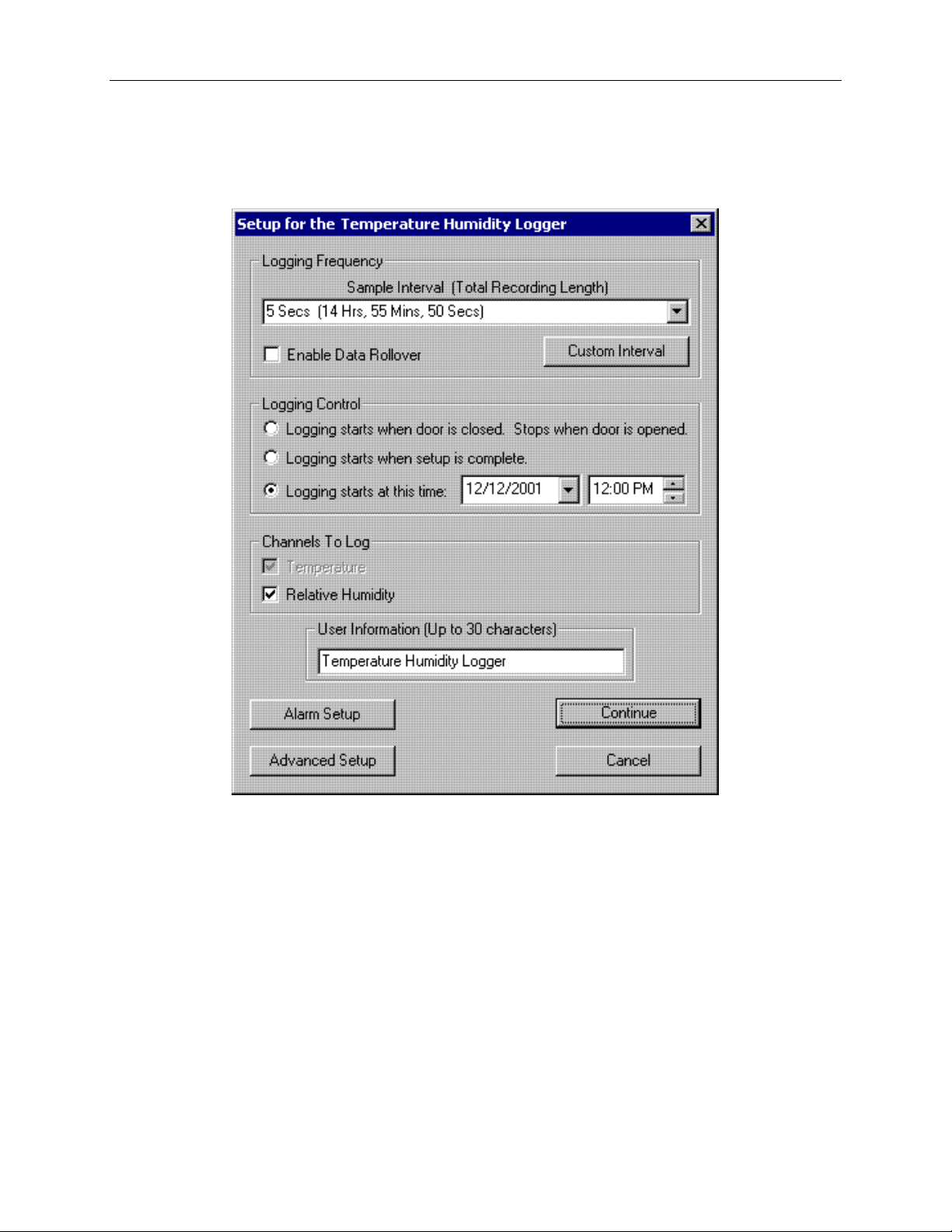
To set your OM-PL logger to start recording data, select Setup fro m t h e Logger menu. The setup options window is
shown below.
• Sample Interval (To tal Recording Length): Select t he sample interval from a predefined list o f intervals.
The sample interval greatly affects the battery life of the logger.
• Custom Interval: Adds your own interval to the sample interval list.
• Enable Data Rollover: Check this box to have the logger continuousl y record the data, overwriting earliest
recorded data. When this box is not checked, logging is stopped when the logger memory becomes full.
• Logging Control: Logging can start i n three ways depending on the selection you make:
o Logging Starts When Door Is Closed, Stops When Door is Opened: Logging will not start until the
sliding door is closed. Logging is stopped when the sliding door is opened. This mode does not allow
real time monitoring of data. Logging must be stopped before the data can be retrieved. When the
sliding door is opened the logger will flash the LED for 10 seconds, if the door is closed again during
this interval, the logging will not stop.
o Logging Starts When Setup is Complete: Logging will start immediatel y once t he Continue button
is pressed, and OK is clicked on the follow-up warning mess age. When lo gging is started in this way,
the sliding door does not have any effect on logging, but can still be used to secure the logger.
o Logging Starts At This Time: Logging will start at the user specified time. There is no limit how far
Page 8
OM-PL Series Data Logger Interface Software Version 2.5x Page 7 /29
in the futur e you can set the logging to s tart. When logging is started in this way, the sliding doo r does
not have any effect on logging, but can still be used to secure the logger.
• Channels to Log: You can elec t to disable unused logger channels. When a channel is disabled, its
memory is allocated to the other chan nels, increasing the total logging time. The total logging time will be
reflected in the Sample Interval window. Depending on the logger, some c hannels are required a nd cannot
be disabled. At least one channel must be enabled for logging.
• User Information: Enter any text you like in this box. This field is used to identify the logger to the user.
You can enter descriptive location, serial number, etc.
• Alarm Setup: Click this button to ope n the Ala rm Setup Window.
• Advanced Setup: Click this b utto n to open the Advanced Set up Wi ndow.
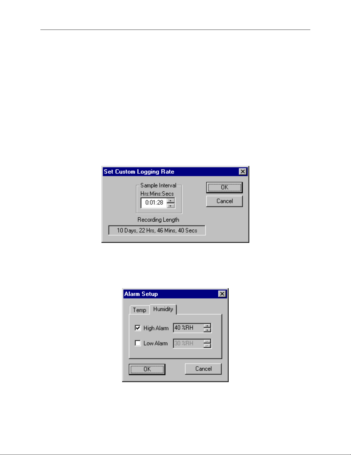
Custom Interval Setup
Commonly used intervals are predefined in the Sample Interval box in the Logger Setup screen. If needed, however,
a custom interval can be d efined by the user. This is done by cli cking on the Custom Interval button in the Logger
Setup screen. The custom interval window will popup, as shown belo w. You can select a custom logging interval
using this window.
Alarm Setup Window
You get to the Alarm Setup Window by c l icking the A l arm Setup but ton in the Logger Setup screen. Most loggers
allow you to set high and/or low alarm thresholds for each logger channel, or disable these alarms. Alarms are set by
entering the thresholds as shown in the window below.
The checkbox to the left of the low/high alarms enables the alarm when checked, and disables the alarm when clear.
Alarm resolution and availability is logger dependent. Check the log ger documentation for more details.
Page 9
OM-PL Series Data Logger Interface Software Version 2.5x Page 8 /29
LED Brightness
LED Flash Frequency
Average Battery Life
Dim
1 seconds
12 months
Dim
2 seconds
16 months
Dim
3 seconds
19 months
Dim
5 seconds
20 months
Dim
10 seconds
22 months
Dim
15 seconds
24 months
Medium
1 seconds
6 months
Medium
2 seconds
9 months
Medium
3 seconds
12 months
Medium
5 seconds
15 months
Medium
10 seconds
19 months
Medium
15 seconds
21 months
High
1 seconds
3 months
High
2 seconds
6 months
High
3 seconds
8 months
High
5 seconds
12 months
High
10 seconds
16 months
High
15 seconds
18 months
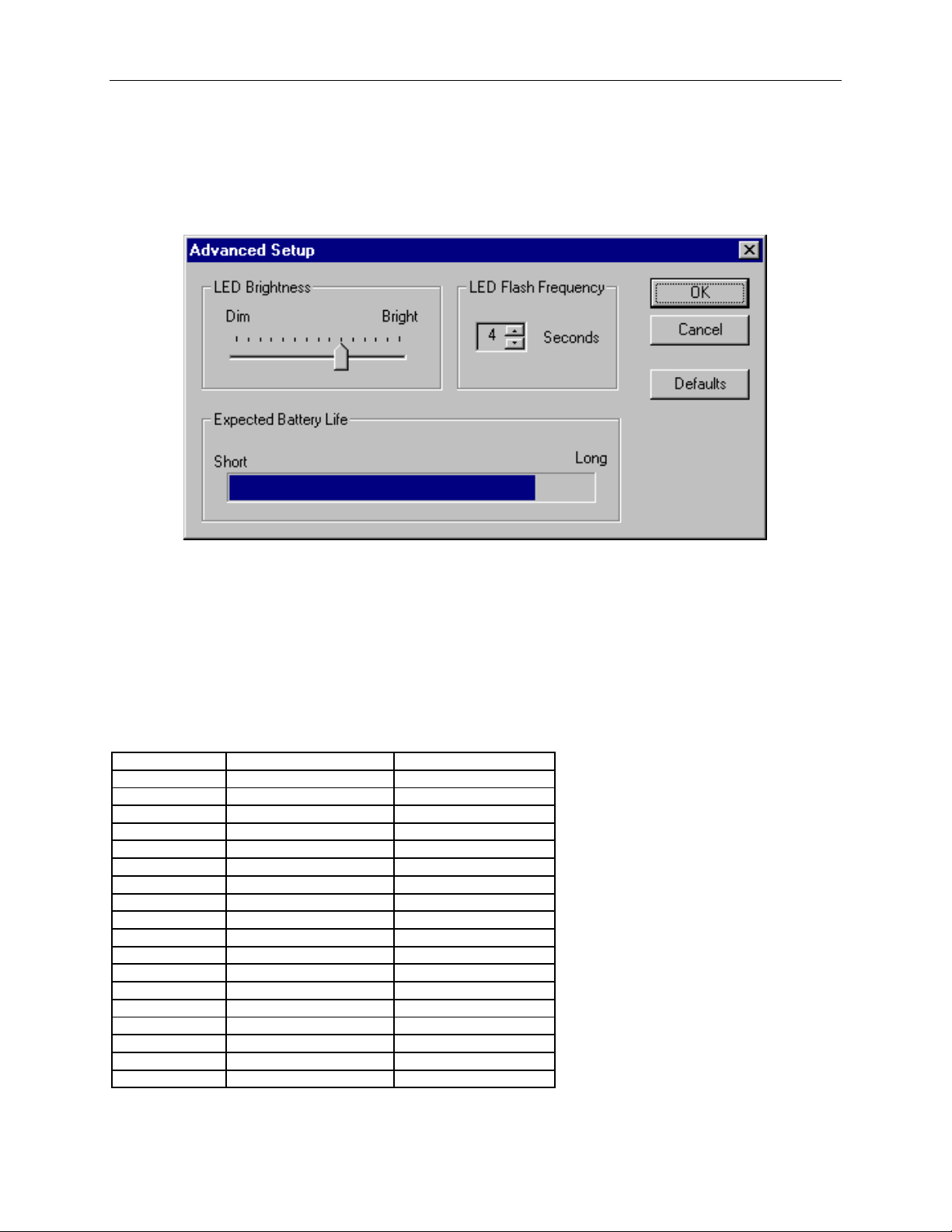
Advanced Setup Window
The Advanced Setup window allows you to setup the status light (LED) flashing parameters during logging. You
can change t he brightness and the fl ash frequency of the status light.
The defaults are:
LED Brightness: Dim
LED Flash Frequency: 5 Seconds
These values provide a good balance between good status indication and battery life. Since the status light uses
power when lit, increasing its brightness and flash frequency will decrease the battery life. The expected battery life
indicator shows how the parameters you selected affect the expected battery life.
Use the table below as a guide on how these parameters affect the battery life. The table assumes a logging interval
of 1 minute and an alkaline battery.
Page 10
OM-PL Series Data Logger Interface Software Version 2.5x Page 9 /29
Status Light
Logger State
Flashes green 5 times in
Power up. The logger wil l flash this sequence r ight after a new battery is installed. This
correctly.
Flashes red then green,
The logger is in delayed logging state . This indicates that lo gging has been initiated, but
from the Setup screen.
Flashes green 4 times, 1
second apart.
Starting to log. This indicates that the logger is starting to log the first sample. This
sequence will only show when the first data sample is logged.
Flashes green every N
seconds.
Logging is in progress, no alarms occurred. The data logged is within the user specified
minimum and maximum va l ues for all the channels.
Flashes red every N
seconds.
Logging is in progress, high or low alarms occurred. At least one data sample logged
was outside the user specified minimum and maximum values.
Flashes red every half
The logger was setup to stop loggin g when the door is closed, and you’ve just closed
light stops blinking, the logging has stopped.
Checking the Logger Status
Logger status can be checked in two ways: By examining the St atus light on the logger, or by selecting Status from
the OM-PL software Logger menu.
Logger Status Light
The table below shows the different logger states that the status light can show. The interval of N seconds
corresponds to the interval that you set in the LED Flash Frequency box in the Advance d Setup Window.
rapid succession.
every N seconds.
second for 10 seconds
indicates that a new battery was in stalle d correctly and that the logger is functioning
the first sample has not been recorded yet. This occurs when delayed logging is chosen
the door. R eopen the do or within the 10 seconds to c ontinue logging. When t he status
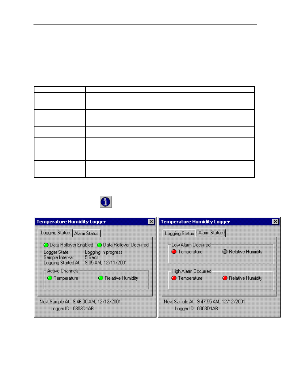
Checking the Logger Status Us ing the Software
Selecting Status from the Logger menu brings up the Logger Status window shown below. You can also bring up
the status window by pressing the
button on the toolbar. The logger status screens are shown below.
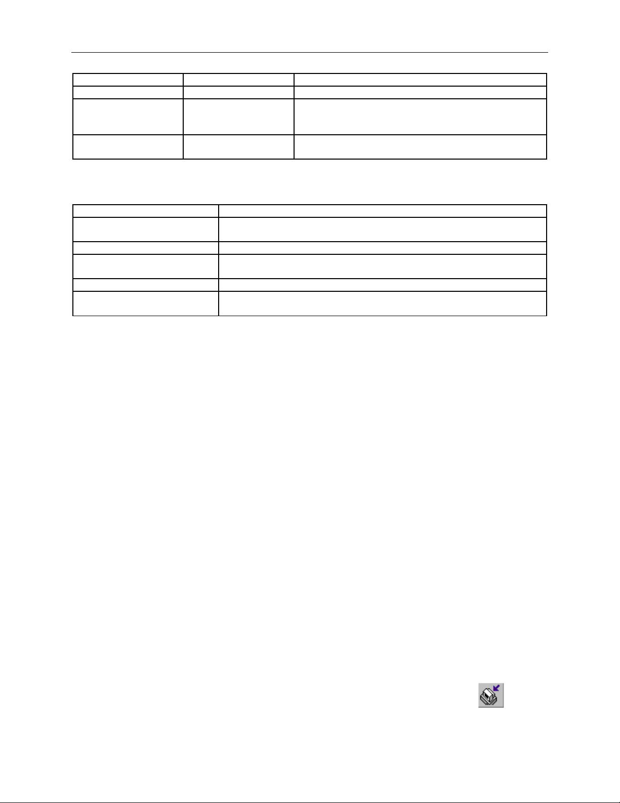
• Data Rollover Enabled and Data Rollover Occurred indicate the status of the data memory in the logger:
Page 11
OM-PL Series Data Logger Interface Software Version 2.5x Page 10 /29
Data Rollover Enabled
Data Rollover Occurred
Status
OFF
OFF
The data rollover feature is not enabled in the logger
ON
OFF
The data rollover feature is enabled, but the recording has not
occurred.
ON
ON
Data rollover has occurred, and the earliest data samples are
being over wr itten with new ones.
State
Description
Powerup: Just Replaced Battery
A new battery has just been placed into the logger. The logger has not
performed logging or calibration since the battery has been inserted.
Idle: Waiting For Setup
The logger i s not logging. It is waiting for a setup command.
Waiting for door to close
Logging has been selected to start when the logger door is closed. The logger is
waiting for the door to close to start logging.
Logging in Progress
The logger i s currently logging data .
Waiting to log (Delayed Logging)
Logging has been selected to start at a future time. The logger is waiting for this
time to arrive to start logging.
reached the end of memory yet, so not data rollover has
• Logger State shows the internal state of the logger:
• Sample Interval shows ho w often the logger is recording the d ata.
• Logging Started At shows at what time the logging has started.
• Active Channels shows what channels the logger was setup to log. The active channels are selected during logger
setup.
• Next Sample At shows the time and date at which the next sample will be recorded. This time may be off when a
very fast sampling period is selected (less than 5 seconds).
• Logger ID shows the unique logger ID assigned to the logger. This logger ID is assigned at the factory and can not
be changed by the user.
• Alarm Status shows what alarms if any occurred for each channel. If the alarm occurred, the corresponding
indicator will light red.
Finishing the Logging Sess ion
There are a number of ways that the logging session can end:
1. When the logger memory becomes full, and data rollover was not selected during logger setup, the logger will
automatically stop logging and e nter the id le sta te .
2. If the logging session was started by closing the logger door (Logging Starts When Door Is Closed, Stops
When Door is Opened option was selected from the setup screen), the logging can be stopped by opening the
door. When the door is opened, the logger will flash the status light red for 10 seconds. If during this period
the door is closed again, the logging will not stop. This helps preventing accid ental stoppage of logging.
3. Selecting End Logging f rom the Logger menu.
4. If the logger detects a low batter y condition, the logging will stop a nd the logger will enter the low battery
state.
5. If the battery is removed from the log ger , logging will stop. No data will be lost.
Once the logging has ended, it cannot be resumed without erasing the logged samples stored in the logger memory.
Retrieving the Data from the Logger
To get the sampled data from the OM-PL logger, co nnect the logger to your computer and click the button on
the toolbar, or select Get Data from the Logger menu. Once the data is transferred from the logger, the data graph
Page 12

OM-PL Series Data Logger Interface Software Version 2.5x Page 11 /29
and listing windows will be displayed.
Logged data can be retrieved from the OM-PL logger at any time. You do not have to stop the logging session to
retrieve the data, unless you selected to have the logger door control the logging.
The graph display will be b la nk if there are less than two data points logged. The listing window will be bla nk i f
there are no data points logged (as can happen during delayed logging, for example).
Automatic Data Retrieval
The OM-PL Interface Software can be setup to automatically load the data into the computer as samples become
available. In this mode the graph and the listing windows are updated automatically with the new data.
To enable this feature follow these steps:
• Make sure that your OM-PL Logger is connected to your computer throug h the OM-PL Interface box.
• Make sure that the logger is loggin g d a ta . A utomatic retrieval is not available when the logger is not logging.
• Manually download the data for the first time by clicking the
from the Logger menu.
• From the Logger menu select Auto Update.
The computer will do wnload data as often as the sampling interval you setup. For instance, if you set your logger to
collect data once every minute, the software will perform a download once a minute. Of course the logger has to be
connected to your computer while the Auto Update is active.
When the Auto Update is active, the software does not change the zoom level of your graph. Instead it scrolls the
graph as new data becomes available.
button on the toolbar, or select Get Data
Page 13
OM-PL Series Data Logger Interface Software Version 2.5x Page 12 /29
Working with the Data Graph
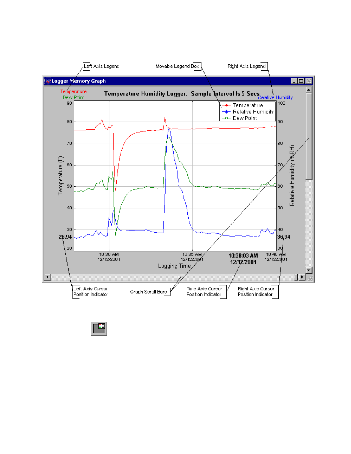
Clicking a nywhere within the graph window activates the graph toolbar buttons and t he graph window features.
• The graph plots each data channel using a different color and dot style. A small rectangular legend shows th e
color and the dot style of each channel. This legend can be moved by clicking the left mouse button while
inside the legend and dragging the legend to where you want i t to be. The legend can be turned ON and OFF
by pressing the
Box option.
• There is an additional legend above each of the Y axis. This legend is the channel name drawn in the same
color as the channel line on the graph. This lege nd helps ide nt ify which channel belongs to which axis. For
instance, in the graph above, the Temperature in red and Dew Point in green correspond to the left Y axis, the
Relative Humidity in blue corresponds to the right Y axis.
• The graph location indicators show the cursor position on the graph. The positio n is shown on each of the axi s
button on the toolbar, or using the menu and selecting the View -> Plot -> Legend
Page 14
OM-PL Series Data Logger Interface Software Version 2.5x Page 13 /29
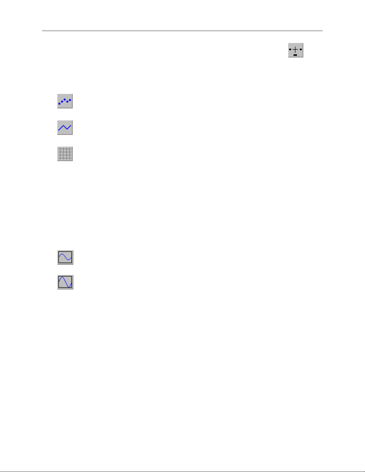
in a slightly larger, bold text. The position ind icators can be turned ON and OFF by pressing the button
on the toolbar, or using the menu and s electing the View -> Plot -> Show Location option.
• During zoom mode, you can use the vertical and horizontal scroll bars to move the graph around.
•
•
•
Note that all the toolbar buttons described above have corresponding menu items under the View -> Plot option.
button turns ON and OFF marks at the data points.
button connects the sample points wi th a line.
button turns the grid lines ON and OF F.
Using the Zoom Feature
There are a number of ways to zoom to the data you would like to see on the screen.
• Graphic Zoom: You can graphically zoom on the portion of the data that is displayed on the screen by
pressing the left mouse button and dragging the box around the part of the graph you would like to zoom to.
You can repeat this until the graph is zoomed to a single point. Pressing the right mouse button re verses the
graphic zoom (causes unzoom).
• Unzoom: Pressing the left mouse but t on, then releasing without draggi ng the mouse causes the graph to
unzoom (zoom out). Once again pressing the right mouse butt on reverses t his zoom.
•
button on the toolbar causes the graph to unzoom to the full scale of the logger. The scale is determined
by the capability of each logger. Choosing Zoom -> Full Scale from the menu has identical effect.
•
• Autoscaling a specific axis: You can also autoscale the time or one of the data axes only, without affect ing the
• Numerical Zoom: Anot her way to sp ecify the zoom is to enter the minimum and maximum limits of the
button on the toolbar c auses the gra ph to unzoom t o the full scale of the data. This means that the
minimum and maximum scale will be about equivalent to the minimum and the maximum of the data.
Choosing Zoom -> Auto Sca le from the menu has identical effect.
other axes. To autoscale the time axis only, choose Time -> Auto Sca le from the Zoom menu. To autoscale
one of the data axis only, choose Auto Scale for the appropriate channel from the Zoom menu.
graph. You can do this individually for the time axis and for each of the data axis. To do this, select Custom
for the appropriate axis from the Zoom menu, and enter the minimum and maximum limits for the axis.
Page 15
OM-PL Series Data Logger Interface Software Version 2.5x Page 14 /29
Data Information Window
The Data Information window is separated into three panes: Data, Data Summary and Alarm Summary. The three
panes are described below.
Data Listing
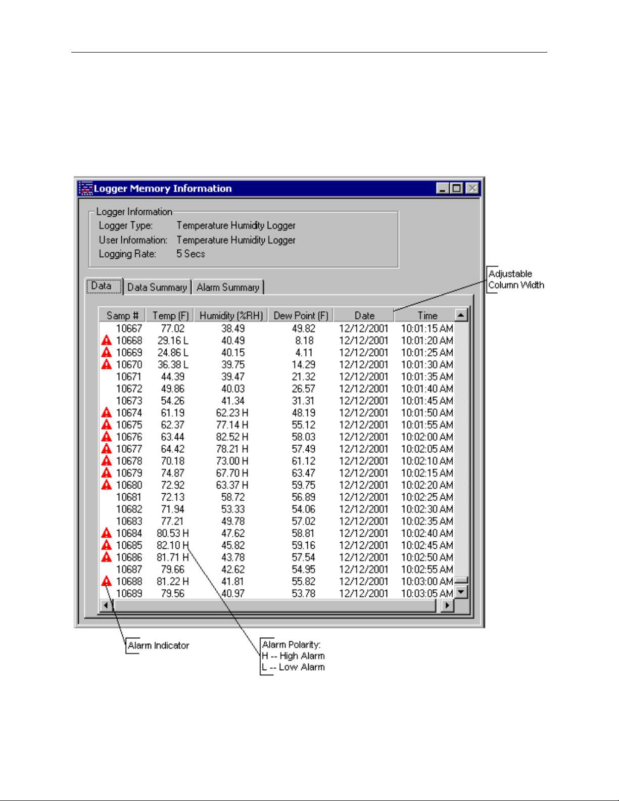
The data listing window is shown be low.
The Data pane lists the data samples collected by the logger. If the data rollover check box in the setup window was
cleared, the earliest data samples are listed. If the data rollover check box was checked, the latest data samples are
listed.
Page 16

OM-PL Series Data Logger Interface Software Version 2.5x Page 15 /29
The column width is adjustable by using the left mouse button and dragging the column to the desired width.
The
icon next to the data sample indicates an alarm condition. That is, one or both the data channels are outside
the minimum and maximum (alarm low and alarm high) thresholds that you set. An L (low alarm condition) or an H
(high alarm condition) is placed next to the sample that is actually outside the threshold.
The amount of data samples shown (and printed) can be reduced by using the data filter.
Data Summary
The data summary pane summarizes the information about the data. The following information is presented:
• Minimum and maximum value for each channel.
• Logging start time, last sample time and the total length of the recording.
• Samples recorded and samples stored. These will be different if data rollover occurred. Samples recorded
count each data sampled by the logger. Samples stored only counts the samples that are actually stored in
logger memor y.
• Logger Info displays the logger id and the total lifetime recordings performed by the logger. The logger id is
unique for each logger and cannot be changed by the user. The total recordings counter increases each time a
new recoding is initiated. It cannot be reset. These two information fields can be used to increase the data
security of your logger .
Alarm Summary
The alarm summary pane lists the time of occurrence and the duration of both high and low alarms for each channel.
Up to 50 separate alarm events are recorded. Alarm memory does not rollover, so only the 50 earliest alarms are
shown.
Using the Data Filter
The data filter helps to display only relevant information in the data window. It can also decrease the number of
printed pages when the data samples are printed. The data filter allows you to:
• Hide sample points when the data did not cha nge sufficiently.
• Show only data points that were sampled in a specified time period.
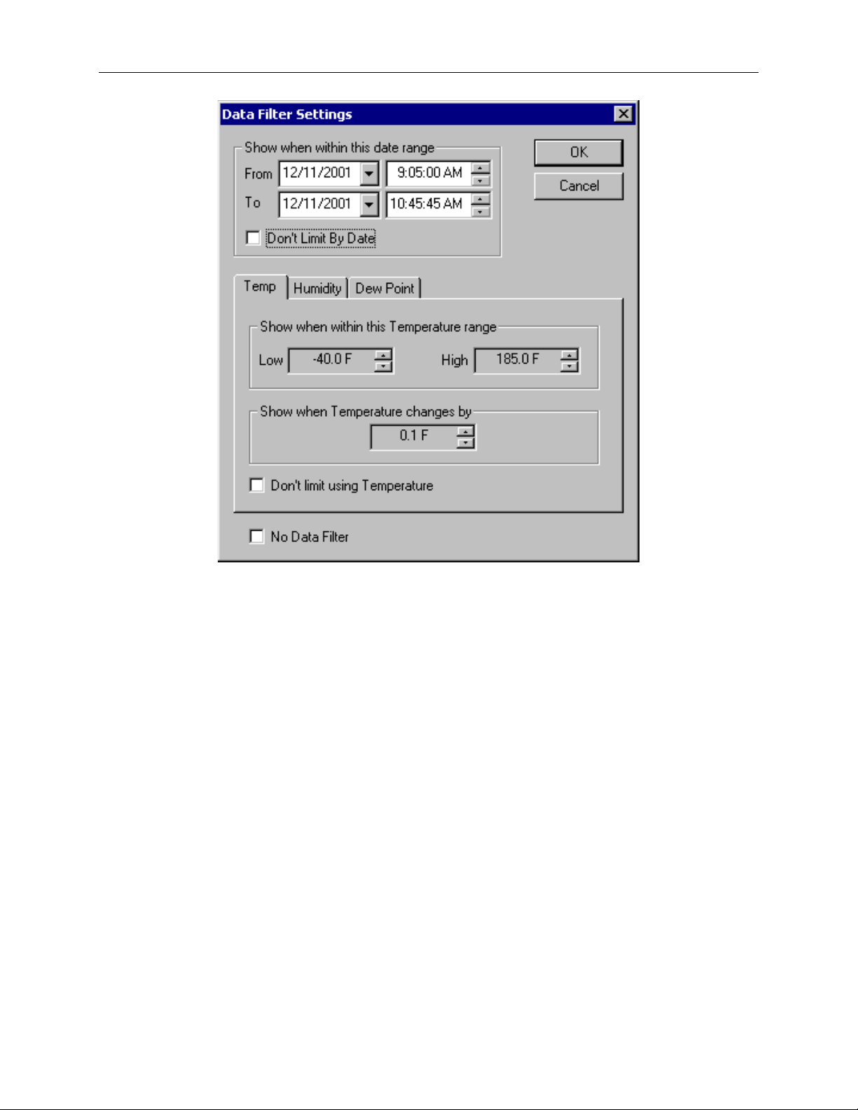
To apply the data filter, select the Data Filter… option from the View menu. The filter selection dialog box is
shown below.
Page 17
OM-PL Series Data Logger Interface Software Version 2.5x Page 16 /29
The filter can be disabled by checking the "No Data Filter" box.
Sample range filtering can be disabled by checking the "Don’t limit using xxxx" box for all the channels or for
specific channels. Channels are selected by clicking on the channel pane.
Date range filtering can be disabled by checking the "Don’t Limit By Date" box.
The filter settings apply consecuti vely. It is therefore very easy to find settin gs that will display no samples at all.
The OM-PL program will give you a warning if you selecte d a filter that results in no sampl es being displayed.
Data Units
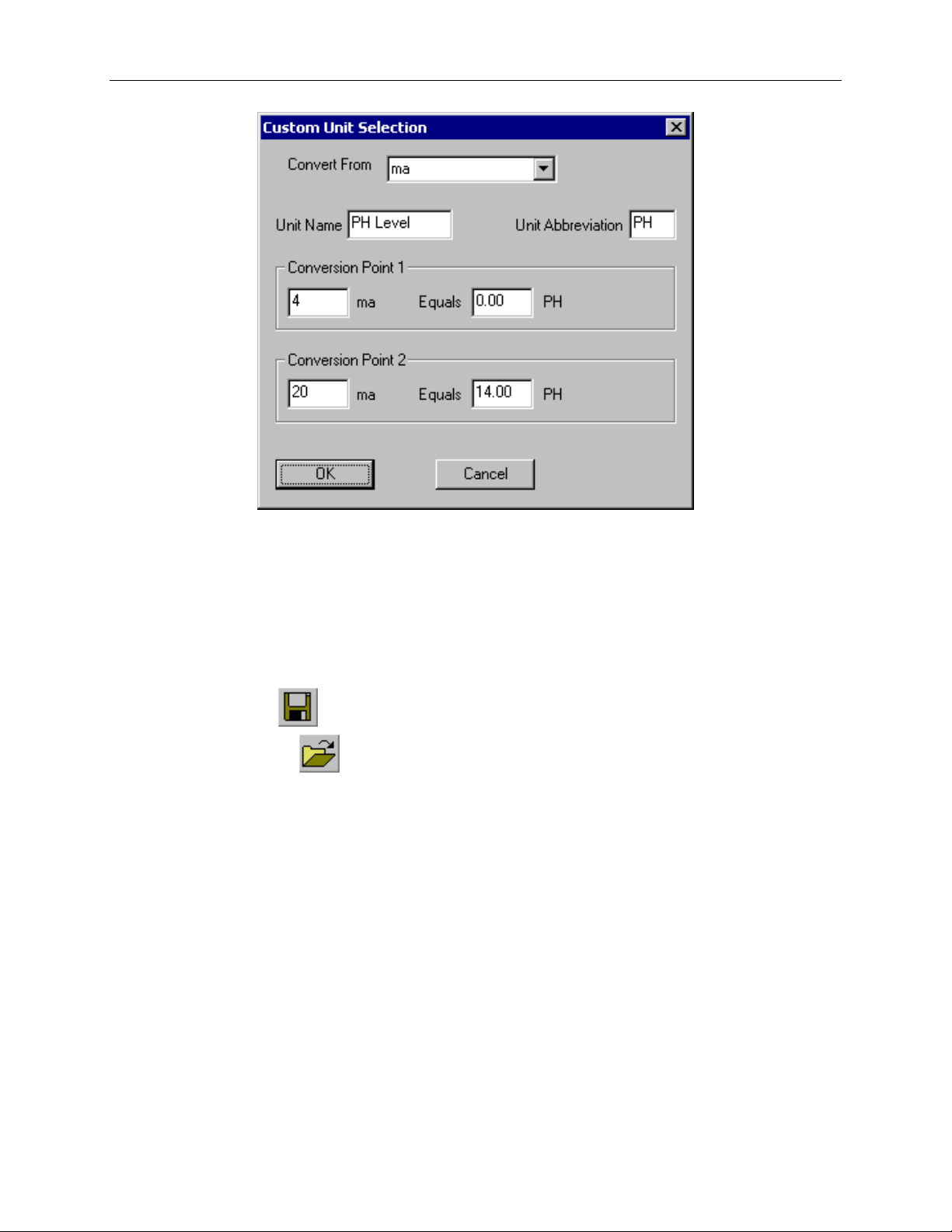
The units for each axis can be changed by selecting Units > from the View menu, and then selecting the axis for
which you would like to change the uni t s . The most widely used units are pr edefined in the progra m. The user can
also choose custom unit s by manually entering t he conversion factors. This is most us eful for the OM-PL420 logger
where the 4 – 20 ma loop usually corresponds to a physical measurement. The window below shows typical entries
for a 4 – 20ma PH sensor.
Page 18
OM-PL Series Data Logger Interface Software Version 2.5x Page 17 /29
Hiding and Viewing Channels
The OM-PL software has the ability to hide channels you do not wish to view. This feature is accessed by selecting
Channels > from the View menu, and t hen deselect ing or sele cting the spe cific channels you wish to hide or view.
The hidden channels do not appear in either the plot or the data listing. They also are not exported through the
export to text and export to Excel features.
Saving and Loading Logger Data
Sample and alarm data retrieved from the logger can be saved in a file for viewing and analyzing at a later time.
To save the data, click the button from the toolbar, or selec t Sav e F ile … from the File menu.
To load a saved file, click the button from the toolbar, or select Ope n File… from the File menu.
OM-PL software stores the data in a proprietary binary format. However, data can be exported to text files that are
compatible with various analy sis to ols. See Exporting the Logger Data section for more details. Exported text file s
cannot be loaded back into the OM-PL software.
Exporting Logger Data
The OM-PL software allows exporting sample, alarm and logging summary data to a text file. I n addition, sample
data can be exported to a Microsoft Excel file.
1. To export sample, alarm and logging summary data to a text file, from the File menu sel ect Export -> Text
File.
2. To export sample data to a Microsoft Excel file, from the File menu select Export -> Excel File.
The file exported to Microsoft Excel is a text file that Excel understands. To read the file into Microsoft Excel,
follow these steps:
1. From the Microsoft Excel application choose Open… from the File menu.
2. In the Open window, under Files of type:, select Text Files.
3. Select the file you exported from the OM-PL program.
4. When the Text Import Wizard window opens, just click the Finish button.
Page 19
OM-PL Series Data Logger Interface Software Version 2.5x Page 18 /29
Printing Logger Data
The OM-PL software can print the data graph, data samples, and a summary page. To print any of these, select Print
from the File menu. You can also view how your data will be p rinted using t he Print Preview option from the File
menu.
Graphs and data samples are printed as they appear on the screen. For graphs, this includes the current zoom detail,
marking of sample points, etc (see Working with the Data Graph for more detail).
For sample output, this means that any data filters applied to the data will be applied to the printed output as well.
Data filters are especially useful for reducing the amount of pages that the data sample printout generates.
Calibrating the Logger
Your OM-PL logger is factory calibrated to an accuracy given in the logger specifications. However, there may be
times when you wish to adjust the calibration of your logger. NIST traceable calibration is available at the factory
for an additional cost. The OM-P L s oftware provides you with a single point o ffset calibration. This calibration can
be used to increase the accuracy of your logger for a small data range. For instance, if your application calls for
logging temperature between 20F and 32F, you may want to calibrate your logger at 26F.
Note: Calibrating the logger erases the data that is stored in logger memory.
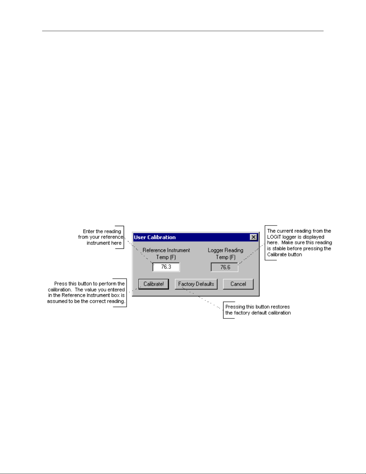
To calibrate your OM-PL logger, select Calibrate… from the Logger menu. For extra security, calibration is
password protected. You must enter the correct password in the Calibration Password window before you’re
allowed to calibrate the unit. The Password Calibration windo w also allows you to change the password.
Once the password is entered correctly, a window asking you to select a channel pops up. Select the channel yo u
would like to calibrate and click OK. Each channel must be calibrated separately.
The User Calibration window ( shown below) will appear.
To perform the calibration:
1. Connect the reference sensor and the OM-PL sensor you are calibrating to the same source. For temperature
and humidity, it is best to place the logger or the sensor in a stable chamber.
2. Bring the setup to the point at which you would like to perform the calibratio n.
3. Wait for your reference instrument and the reading in the "Logger Reading" box to stabilize.
4. Enter the reading from your reference instrument in the "Reference Instrument" box, and hit the Calibrate!
button.
Page 20
OM-PL Series Data Logger Interface Software Version 2.5x Page 19 /29
Changing The Calibrati on P a s sw ord
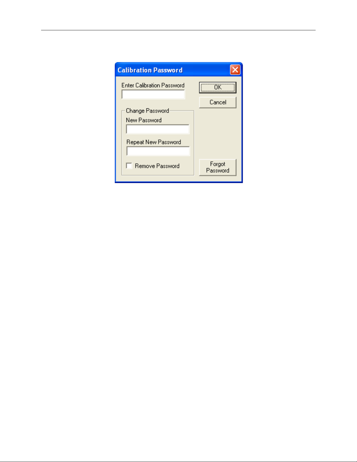
To change the calibration password select Calibrate… from the Logger menu.
When the Calibration Password window is displayed, follow these steps:
Enter the current calibration pa ssword in the "Enter Calibration Password" box. Each OM-PL logger is factory
configured not to have a password (do not enter anything in this box).
Enter the new password i n the "New P assword" box.
Enter the new password again in the "Repeat New Password" box.
Click OK.
You can also remove password protection (restore factory default empty password) by checking "Remove
Password".
If you forgot the calibration password and need to reset it, click the "Forgot Password" button. This will reset
the logger password to factory default (empty password). Resetting the password in this way will erase the data
stored in the logger and reset the recording counter to 0.
Setting the Logger's Real Ti m e Clock
The OM-PL lo ggers have an internal Real Time Clock. This clock is updated every seco nd. During logging, the time
stamps of the data samples and of the alarm occurrences are set by the Real Time Clock.
When you first connect a new battery to the logger and setup your logger for the first time, the OM-PL software
automatically matches the logger clock to your computer’s clock. However, you can also manually set the logger’s
real time clock.
To set the logger’s Real Time Clock, from the Logger menu select Set Cloc k…. Make sure that "Use Windows
Clock" is unchecked, then enter the current date and time in the appropriate fields.
You cannot set the Real Time Clock while logging is in progress. You must end logging before the Real Time Clock
can be set.
Data Security
The OM-PL lo ggers and the OM-PL software have a number of features to prevent third parties from tampering
with and/or falsifying the logged data. The security features are as follows:
• After initiating the data logging, close the logger d oor and insert a lock into the hole in the logger case.
This prevents the logger door from being open, which physically prevents a third party from connecting to
the logger and changing or accessing the data.
• Each logger comes with a factory set unique logger id. The logger id is always disp layed in the logger
status window and the data summary window. The logger id cannot be written by the user. This prevents
Page 21
OM-PL Series Data Logger Interface Software Version 2.5x Page 20 /29
Logging Sample
Interval
Battery Life
1 second
3 months
5 seconds
10 months
10 seconds
15 months
30 seconds
19 months
1 minute
20 months
1 Hour
22 months
somebody from switching loggers once the data is collected.
• Once loggi ng has started, parameters such as sample rate, logging start time, logging sample counter, etc.
cannot be changed without first clearing the recorded temperature and the alarm data. This prevents
gathering many data samples at a fast sample rate and then lowering the sample rate to give the appearance
that the data was recorded over a longer period of time.
• The OM-PL lo gger has an i nt ernal recording session counter. This counter counts how many times the
logger was setup to record data. This counter cannot be reset even by unplugging t he battery. This counter
can be used to guarantee that the OM-PL data has not been clear ed during a given period of t ime. If you
know the val ue of the sessi on after the logging session has started, you can guarantee that the OM-PL data
has not been falsified if the session counter did not change. The session counter is available in the data
summary window. These counters are read only and cannot be written to externally.
• The OM-PL internal real time clock cannot be changed during the logging session.
• The calibration data is passwor d protected. This prevents a third party from recalibrating the unit to yield a
false data and alarm reading.
• Calibrating the logger erases the logged data from the logger memory. This prevents somebody from
adjusting the logged data after a recording is made.
Logger Battery Replaceme nt
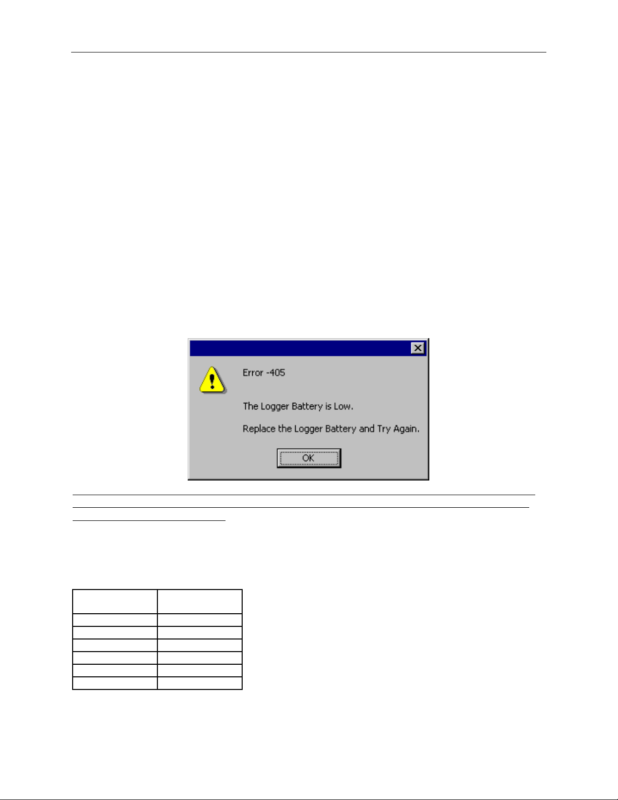
Replace the logger battery periodically to avoid loosing data, due to the battery becoming low. When a low battery
condition is detected, the logger will stop any logging session and will enter a low battery state. In this state any
access to the logger will result in the following error:
Before replacing the battery, make sure that the logger is not connected to the computer. If the logger is
connected to the computer when the battery is replaced, the low battery condition will not be reset and
the logger will remain inoperable. If this situation occurs, disconnect the battery, disconnect the logger from the
computer, and connect the battery once more.
When the battery is replaced correctly, the logger status light will flash green five times in rapid succession.
General guidelines as to how long a battery will last is shown in the table below. It is assumed that the logger uses a
fresh alkaline battery, the status flash frequency is set to 5 seconds, and the status flash is set to the dimmest setting.
Page 22
OM-PL Series Data Logger Interface Software Version 2.5x Page 21 /29
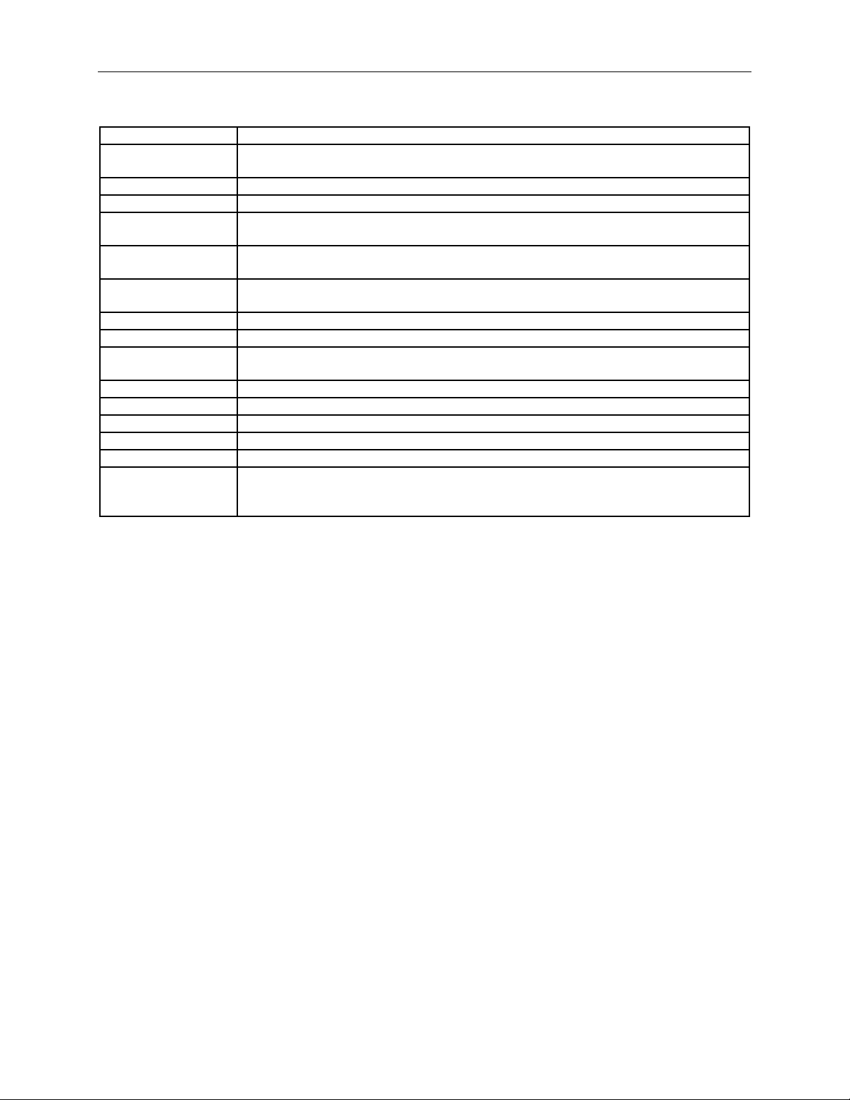
Sampling Interval
User selectable from 1 second to 18 hours, in 1 second increments.
Interface
OM-PLLS Kit: COM (RS232) serial port.OM-PLLS-USB Kit: USB Port (Not compatible
with Windows 95 or Widnows NT).
Alarms
Visual alarms with user selectable low and high thresholds for every channel.
Alarm Memory
Up to 50 alarm events. Alarm start ti me and a la rm duration is stored.
Data Security
Locking sliding door prevents physical access to the logger data. Unique factory set logger
id. Data collection session counter .
Compatibility
Windows 95 and above. OM-PLLS-USB USB Kit is not compatible with Windows 95 or
Windows NT.
Mi n imu m Sys tem
Requirements
8MB of RAM, 2M of disk space, 800 x 600 resolution, 1 free COM port or a free USB
port.
Recording Start
On door close, immediate after setup, or at a user specified date and time.
Recording Mode
Stop on memory full, or continuous recording with memory rollover.
Real Time Status
Visual indication through the status LED. User selectable status display frequency and
LED brightness. Software real time status.
User Calibration
Password protected calibration for each channel.
User Messag e
Up to 30 characters.
Logger Channels
User selectable. Disabling channels increases the storage capacity of the other channels
Units
US and Metric. User selectable units.
Data Format
Custom format exportable to text or Excel spreadsheet.
Real Time Monitoring
Logger can be permanently connected to the computer and used as a real time,
connected to the computer.
OM-PL Logger Interface Software Specifications
multichannel sensor with logging cap a bility. Battery does not dra in when logger is
OM-PLT2: Internal / Ex t er na l Tem pe ra t ure Logger
The OM-PLT2 Data Logger is a precision instrument for recording the temperature of the surrounding environment
and/or the temperature of the external temperature probe. The remote probe allows the OM-PLT2 to record internal
and external temperature simultaneously. The external temperature probe is interchangeable and replacement probes
are available. The OM-PLT2 can store up to 21,500 temperature readings when a single probe (internal or external)
is used. When both probes are enabled, 10,750 temperature readings can be recorded for each probe, as well as and
the temperature difference between the internal and external probes.
The OM-PLT2 Data Logger has an internal temperature sensor and an external temperature probe. The external
probe standard length is 15ft. It can be extended up to 300ft using an optional extension wire.
Connecting the External Te m pera t ure Probe t o OM-PLT2
The OM-PLT2 exter nal temperature probe is not polarized, which means that it does not matter in what order the
two wires are connected to the logger.
OM-PLT2 Battery Selection
As with all the OM-PL loggers, you have a choice between using an Alkaline or a Lithium 9V battery. The loggers
can operate twice as long Lithium battery than on an Alkaline battery. For the OM-PLT2 logger selecting the rig ht
battery has another important consideration. The internal temperature sensor is rated for temperatures between -40°F
to 150°F (-40°C to 65°C). However, this range can only be achieved when using a Lithium battery. If you are using
an Alkaline battery, the internal sensor temperature range is reduced to 32°F to 140°F (0°C to 60°C). This is because
the Alkaline battery is not rated outside of this temperature range.
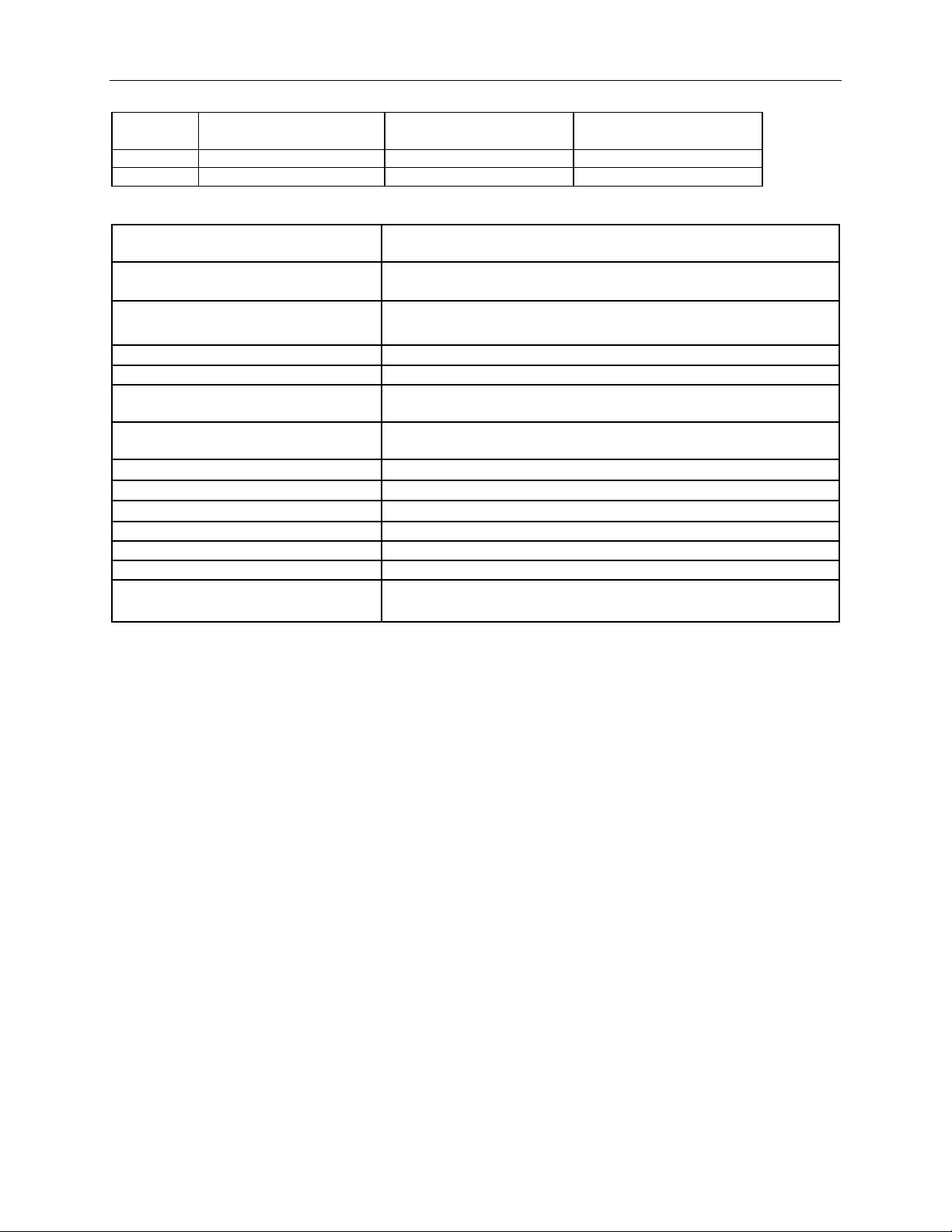
The temperature ranges are summarized in the table below.
Page 23
OM-PL Series Data Logger Interface Software Version 2.5x Page 22 /29
Battery
Logger Operating
Temperature
Internal Sensor
Temperature Sensor
External Probe
Temperature Range
9V Alkaline
32°F to 140°F (0°C to 60°C)
32°F to 140°F (0°C to 60°C)
-40°F to 150°F (-40°C to 65°C)
9V Lithium
-40°F to 150°F (-40°C to 65°C)
-40°F to 150°F (-40°C to 65°C)
-40°F to 150°F (-40°C to 65°C)
Sample Point Capacity
21,500 points for single channel. 10,750 points per channel for dual
channel.
External Probe
-40°F to 150°F (-40°C to 65°C), 15ft standard. Can be extended to 300
ft.
Logger Operating Temperature Range
32
-40°F to 150°F (-40°C to 65°C) using Lithium Battery.
Storage Temperature
-40°F to 170°F (-40°C to 77°C)
Ambient Operating Relative H umidity
0% to 95% non-condensing
Alarms
Over and under alarms for internal and external sensors. Alarms are not
available for temperature difference between the sensors.
Calibration
User single point offset calibra tion is available through software for both
internal and external sensors.
Time Accuracy
+/-100ppm @75°F
Temperature Resolution
0.1°F (0.05°C)
Temperature Accuracy
+/- 1.0°F (0.5°C)
Dimensions
3’’ x 2.5" x 1.1’’ (7.6cm x 6.4cm x 2.8cm)
Weight
2.5 Oz (71g)
Power Source
9V Alkaline or Lithium battery.
Battery Life (average use)
19 Months using Alkaline Battery.
38 Months using Lithiu m Battery.
OM-PLT2 Specifications
°F to 140°F (0°C to 60°C) using Alkaline Battery.
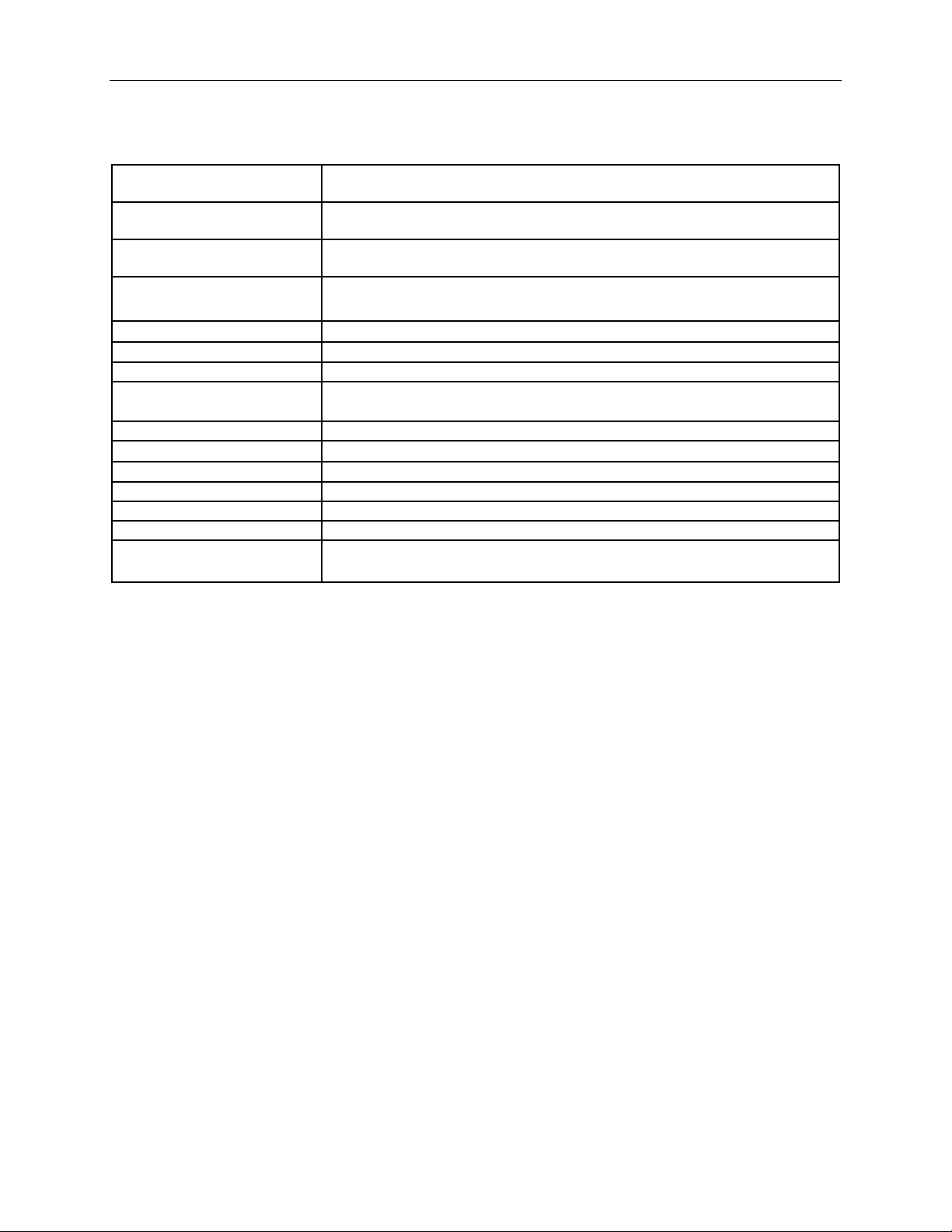
OM-PLTH: Temperature Humidity Logger
The OM-PLTH i s a self-contained, precision instrument for recording the temperature and humidity of the
surrounding environment. The OM-PLTH can store up to 21,500 temperature samples, or up to 10,750 of
temperature and humidity samples. In addition to Temperature and Humidity, the OM-PL software computes and
displays the Dew Point and the Wet Bulb Temperatures.
By default, the OM-PL software will only show the Temperature, Humidity and Dew Point data. To view the Wet
Bulb Temperature data, from the View menu, select Channels >, and click on Wet Bulb. You can fi nd mor e
information in the Hiding and Viewing Channels s ection.
The OM-PLTH logger temperature and humidity sensors are open to the air. It is therefore important to ensure that
water does not get into the unit. This is especially important in high humidity situations (90% RH and above) where
water may condense inside the logge r, damagin g the logger.
Caution!!!
Care must be taken to ensure that the logger is not operating in
condensing conditions. This means that the dew point
temperatu re mu st be bel ow the ambie n t tem per at u re.
Condensati on may dam age th e humi di ty se ns o r and the logger
electronics.
Page 24
OM-PL Series Data Logger Interface Software Version 2.5x Page 23 /29
Sample Point Capacity
21,500 points for temperature only. 10,750 points of temperature, humidity, dew
point, and wet bulb temperature.
Alarms
Over and under alarms for temperature and humidity. Dew point and wet bulb
alarms are not available. Humidity alarms are accurate to +/- 5% RH.
Calibration
Humidity is factory calibrated. Use r single point offset calibration is available
through software for both temperature and humidity.
Operating Temperature
-40°F to 150°F (-40°C to 65°C)* using Lithi um Ba tt ery.
Storage Temperature
-40°F to 170°F (-40°C to 77°C)
Time Accuracy
+/-100ppm @75°F
Relative Humidity Range
0% to 99.9%RH, non condensing.
Relative Humidity Accuracy
+/- 2% full scale, from 0% to 95% RH for temperatures between 32°F and 140°F
(0°C to 60°C)
Relative Humidity Resolution
0.1%RH
Temperature Accuracy
+/-2°F (1°C)
Temperature Resolution
0.1°F (0.05°C)
Dimensions
3’’ x 2.5" x 1.1’’ (7.6cm x 6.4cm x 2.8cm)
Weight
2.5 Oz (71g)
Power Source
9V Alkaline or Lithium battery.
Battery Life (average use)
40 Months using Lithiu m Battery.
OM-PLTH Specificati ons
32°F to 140°F (0°C to 60°C) using Alkaline Battery.
20 Months using Alkaline Battery.
*Note that humidity sensor accuracy is only guaranteed for temperature range of 32°F to 140°F (0°C to 60°C).
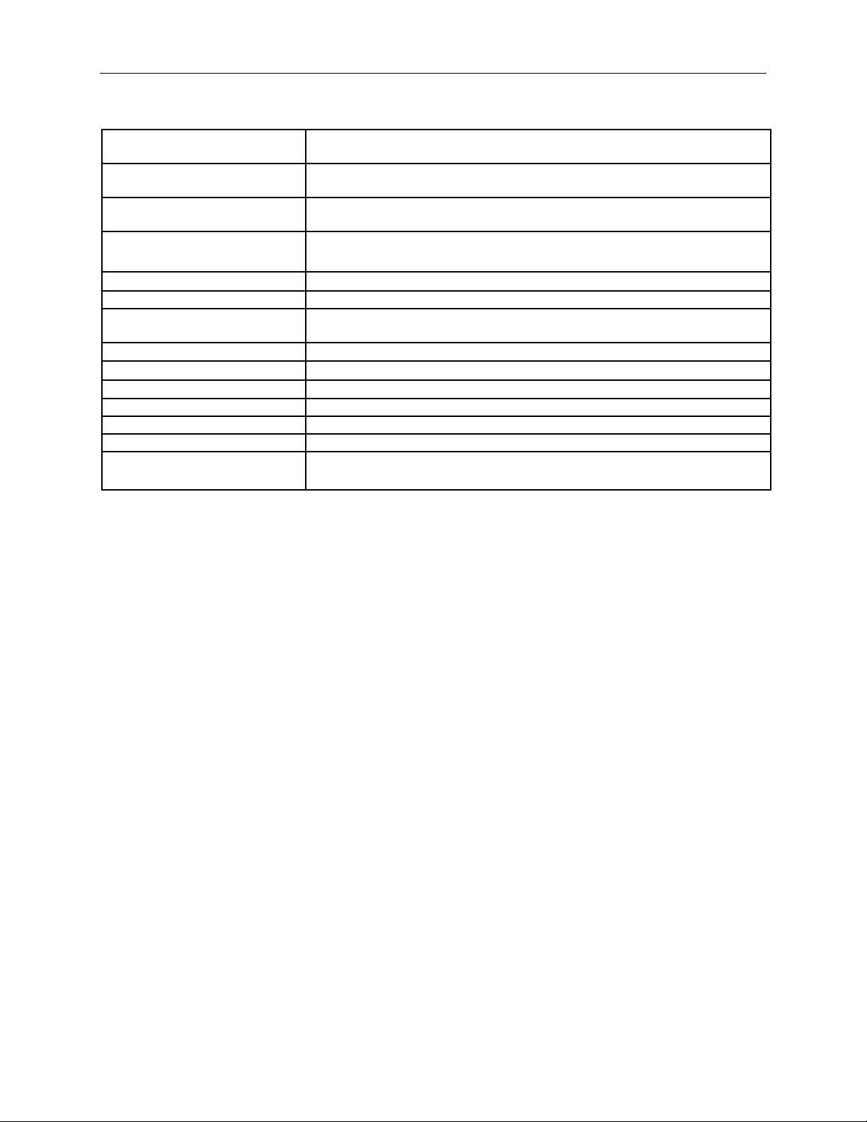
OM-PLTT: Dual Exter na l Tem pe ra t ure Logge r
The OM-PLTT is a precision instrument for recording the temperature of two independent temperature probes. Each
temperature sensor is enclosed within a 4 inch stainless steel jacket. The OM-PLTT temperature probes are
interchangeable, and replacement probes are available. Each temperature sensor cable is 6ft long. The OM-PLTT
can store 21,500 temperature samples when using a single probe. The OM-PLTT can store 10,750 temperature
samples when using both probes. The temperature difference between probe 1 and probe 2 is also recorded.
The probe’s stainless steel tip ca n b e immersed in any solid or liquid that is co mpatible with 300 series stainless
steel.
Compatible substances include, but not limited to: Water, steam, oil, Freon, hydraulic fluid, natura l gas, propane.
Incompatible substances include, but not limited to: Acids such as nitric acid, sulfuric acid and hydrochloric acid .
Any materials that are corrosive to steel.
Note that only the probe steel tip is media compatible. The probe cable is not water
proof.
Page 25
OM-PL Series Data Logger Interface Software Version 2.5x Page 24 /29
Sample Point Capacity
21500 temperature points for a single probe. 10750 temperature points and
temperature difference, when using both probes.
Alarms
Over and under alarms for each external temperature probe. Alarms are not
available for temperature difference.
Calibration
User single point offset calibra tion is available through software for both
temperature sensors.
Logger Operating Temperature
-40°F to 150°F (-40°C to 65°C) using Lithium Battery.
Time Accuracy
+/-100ppm @75°F
Relative Humidity Range
0% to 95%RH non condensing
Probe Specification
Media compatible 4 inch stainless steel tip. 6ft cable. The probes are
interchangeable.
Probe Temperature Range
-50°F to 300°F (-46°C to 150°C)
Temperature Accuracy
+/-2°F (1°C)
Temperature Resolution
0.1°F (0.05°C)
Dimensions
3’’ x 2.5" x 1.1’’ (7.6cm x 6.4cm x 2.8cm)
Weight
2.5 Oz (71g)
Power Source
9V Alkaline or Lithium battery.
Battery Life (average use)
40 Months using Lithiu m Battery.
OM-PLTT Specificati ons
Range
32°F to 140°F (0°C to 60°C) using Alkaline Battery.
20 Months using Alkaline Battery.
OM-PLPT: Pressure Tem per a t ure Logger
The OM-PLPT data logger is a precision instrument for recording pressure and temperature. The logger can store up
to 21,500 data points, when it is setup to record either pressure or temperature (but not both). The logger can store
up to 10,750 points, when it is setup to record both pressure and temperature.
The external temperature probe is interchangeable and replacement probes are available. The pressure sensor is not
interchangeable. Each logger is individually calibrated to the pressure sensor at the factory.
The pressure sensor is media compatible.
Compatible substances include, but not limited to: Water , ste am, oil, Freon, hydraulic fluid, natura l gas, propane.
Incompatible substances include, but not limited to: Acids such as nitric acid, sulfuric acid and hydrochloric acid .
Any materials that are corrosive to steel.
Note that only the probe sensor inside the probe is media compatible. The outside of the pressure
sensor and the pressure sensor cable are not waterproof. Do not immerse the entire sensor! The
temperature sensor is also not waterproof.
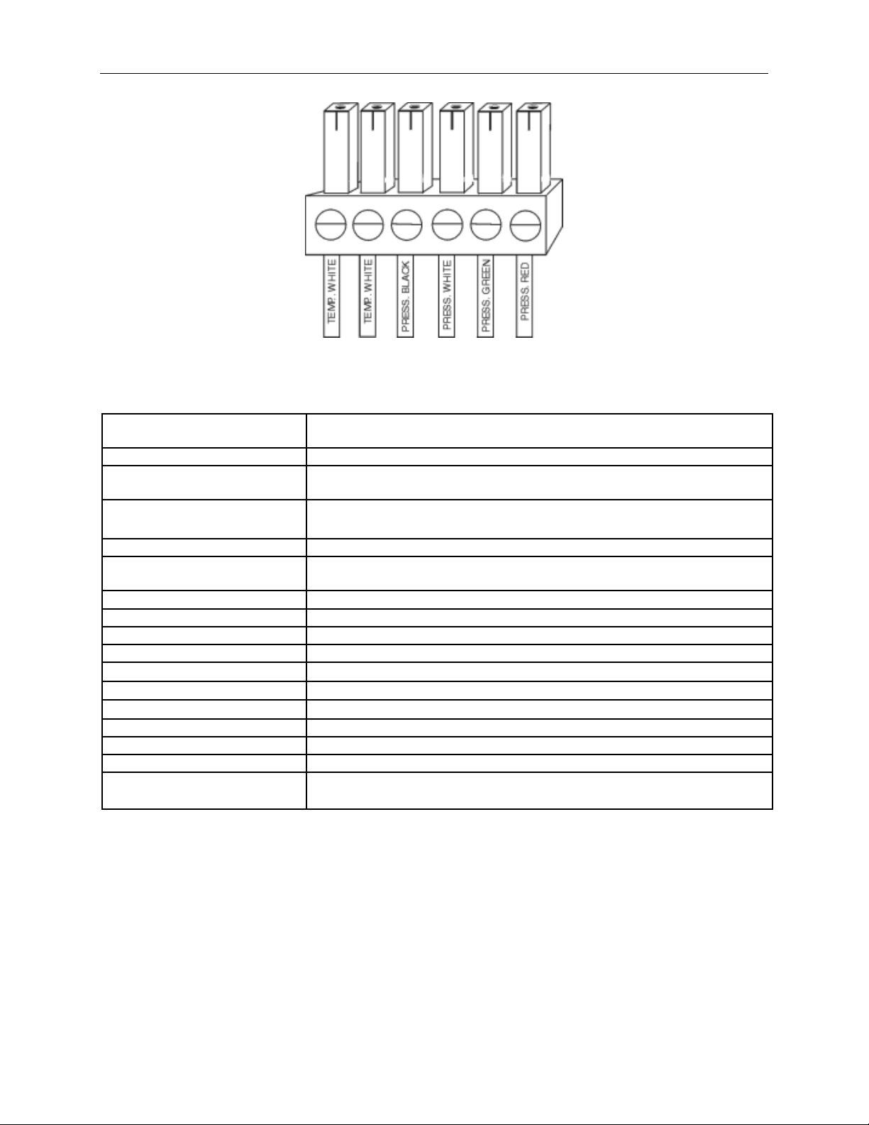
Connecting the Sensors to the OM-PLPT
The temperature and pressure sensors come preconnected to the 6 position connector plug. The pressure sensor
wires are color coded: black, white, green and red. The temperature probe has two white wires and does not have a
polarity. To reconnect the temperature and pressure probes, use the diagram below:
Page 26
OM-PL Series Data Logger Interface Software Version 2.5x Page 25 /29
Sample Point Capacity
10,750 data points when pressure and temperature are recorded together. 21,500
points when recording only pressure or only temperature.
Alarms
Over and under alarms for pressure and temperature probes.
Calibration
Factory calibrated for the pressure sensor. User single point offset calibration is
available through software for both pressure and temperature.
Logger Operating Temperature
-40°F to 150°F (-40°C to 65°C) using Lithium Battery.
Pressure Sensor
Media compatible stainless steel sensor. 6ft cable.
Pressure Sensor Operating
Temperature
32°F to 130°F (0°C to 54°C)
Time Accuracy
+/-100ppm @75°F
Pressure Range
0 to 500 PSI, 0 to 1000PSI for OM-PLPT1000
Pressure Accuracy
+/- 3 PSI, +/-5 PSI for OM-PLPT1000
Pressure Resolution
0.15 PSI, 3PSI for OM-PLPT1000
External Temperature Probe
-40°F to 150°F (-40°C to 65°C), 15ft standard. Can be extended to 300 ft.
Temperature Accuracy
+/- 1.0°F (0.5°C)
Temperature Resolution
0.1°F (0.05°C)
Dimensions
3’’ x 2.5" x 1.1’’ (7.6cm x 6.4cm x 2.8cm)
Weight
2.5 Oz (71g)
Power Source
9V Alkaline or Lithium battery.
Battery Life (average use)
38 Months using Lithiu m Battery.
OM-PLPT Specificat ions
The external temperature probe standard length is 15ft. It can be extended up to 300ft.
32°F to 140°F (0°C to 60°C) using Alkaline Battery.
19 Months using Alkaline Battery.
OM-PLCV: AC Current, AC Volta ge Logger
The OM-PLCV data logger is a precision instrument for recording AC current and AC voltage. AC cur r ent is
sampled using the supplied clamp probe. The logger can store up to 21,500 data points, when it is setup to record
either AC current or AC voltage (but not both). The logger can store up to 10,750 points, when it is setup to record
both AC current and AC voltage.
Each logger is factory calibrated. This means that the clamp probes are not interchangeable.
Page 27
OM-PL Series Data Logger Interface Software Version 2.5x Page 26 /29
Connecting the OM-PLCV to Electrical Equipment
Before connecting to any equipment follow these precautions:
• Make sure that the wires are securely attached to the connector and that no uninsulated portion of the wire
is visible after the connection is made.
• Make sure that there is no strain that could pull the leads out of the OM-PLCV connector.
• Make sure that the leads will not interfere with any moving pieces of equipment a nd will not pull loose any
wires or other connections.
To measure the voltage, conne c t the two voltage clip leads to the points at which the voltage is being measured.
To measure the current, place the clamp probe around the wire in which the current is being measured.
Electrical connection to any type of operating equipment is Dangerous!
The OM-PLCV leads and current pro be should onl y be connected when it has been
determined th at t he pow e r is off and the eq uipm e nt is sa fe to to u ch.
It is sugges ted that you always remove the OM-PLCV voltage leads before
connecting the OM-PLCV to your computer!
If you decide to connect the OM-PLCV to a voltage source while the OM-PLCV is connected
to your computer, make sure to read the "Connecting the OM-PLCV to both the Computer
and a Voltage Source" section for instructions.
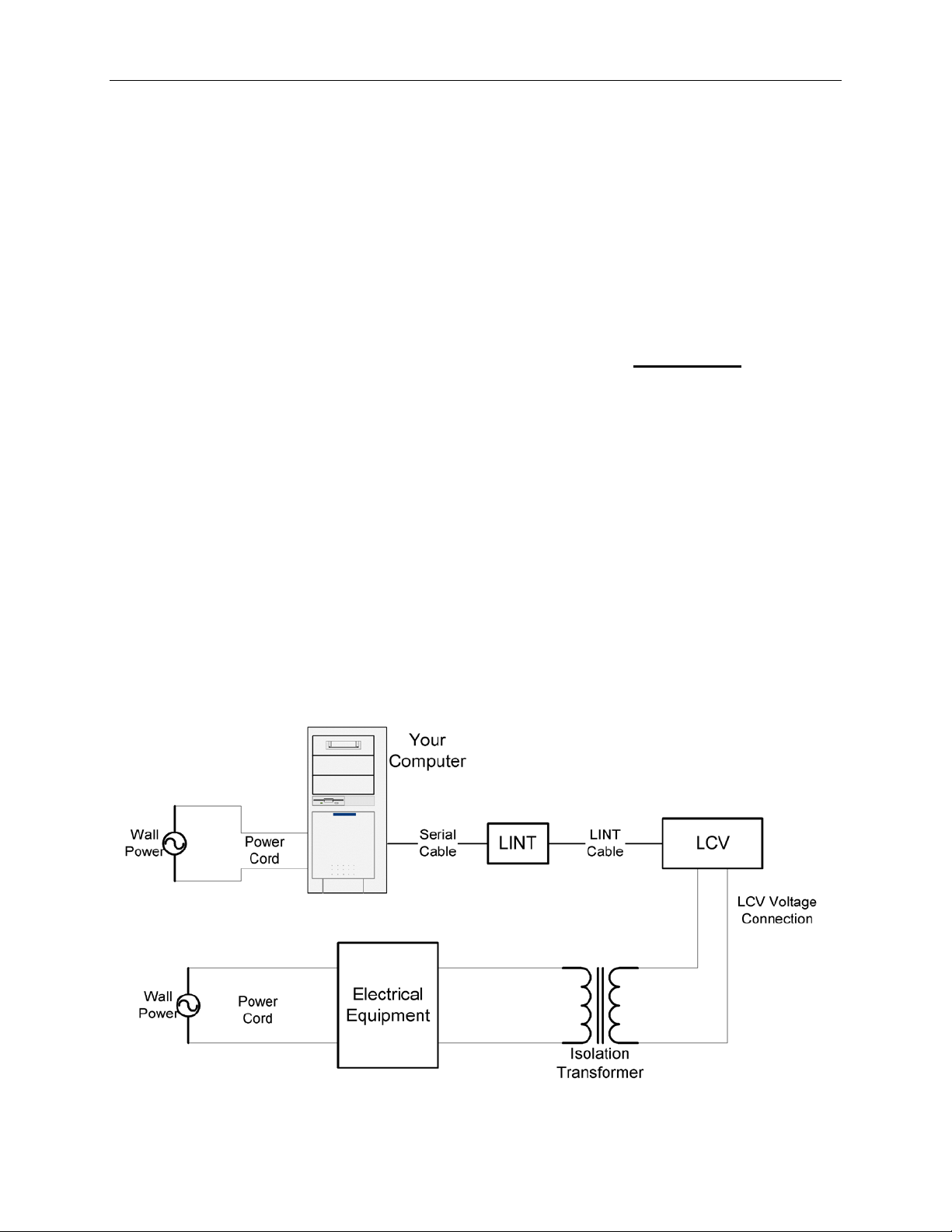
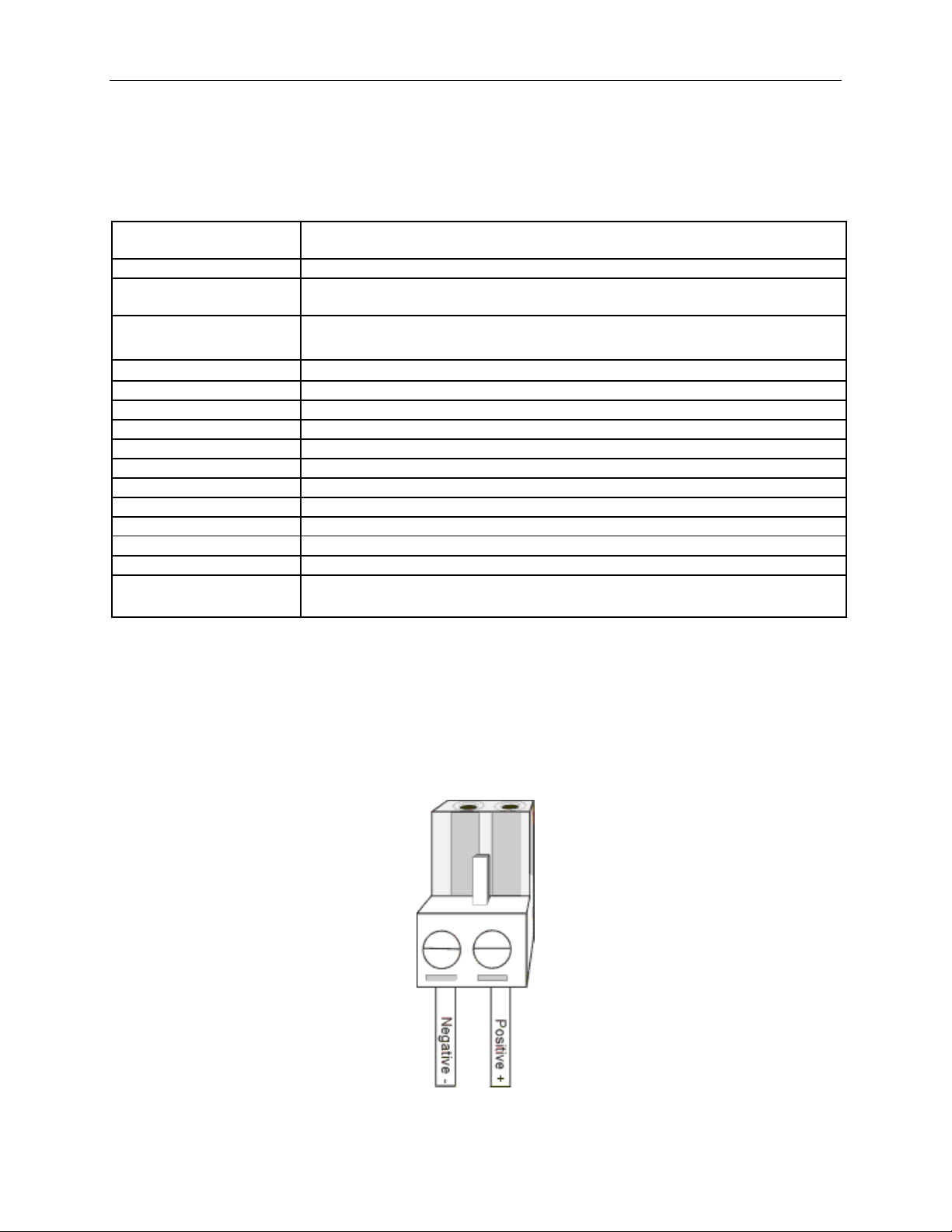
Connecting the OM-PLCV to both the Computer and a Voltage Source
Although it is not recommended, it is sometimes necessary to connect the OM-PLCV to a voltage source while the
OM-PLCV is connected to a PC, for instance, if real time monitoring is required. If both the computer and the
voltage source you are connecting to are connected to wall power (as is true in most cases), an isolation transformer
must be used between the voltage source and the OM-PLCV vo ltage inputs . An isolation transformer does not have
electrical connections between the primary and secondary windings. The recommended connection is shown in the
figure below.
Page 28
OM-PL Series Data Logger Interface Software Version 2.5x Page 27 /29
Sample Point Capacity
10,750 data points when AC current and AC voltage are recorded together. 21,500
points when recording only AC current or onl y AC voltage.
Alarms
Over and under alarms for AC current and AC voltage.
Calibration
AC current and AC voltage inputs are factory calibrated. User single point offset
calibration is available through software for both AC current and AC voltage.
Operating Temperature
32
-40°F to 150°F (-40°C to 65°C) using Lithium Battery.
Time Accuracy
+/-100ppm @75°F
Relative Humidity Range
0% to 95%RH non condensing
Current Range
0 to 300 Amp AC
Current Accuracy
+/- 5%
Current Resolution
0.1 Amp AC
Voltage Range
0 to 500 Volts AC
Voltage Accuracy
+/- 1 VAC
Voltage Resolution
0.1 VAC
Dimensions
3’’ x 2.5" x 1.1’’ (7.6cm x 6.4cm x 2.8cm)
Weight
2.5 Oz (71g)
Power Source
9V Alkaline or Lithium battery.
Battery Life (average use)
18 Months using Alkaline Battery.
36 Months using Lithiu m Battery.
If an isolation transformer is not used, the voltage read by the OM-PLCV will not be accurate. The actual reading
may be close to Actual Voltage + Line Voltage, or Actual Voltage – Line Voltage. For instance, if the OM-PLCV is
connected directly to 120V line, without the Isolation Transformer, the reading may be 240V or 0V, depending on
how the computer power supply is wired.
OM-PLCV Specifications
°F to 140°F (0°C to 60°C) using Alkaline Battery.
OM-PL420: 4 - 20ma Current Loop Logger
The OM-PL420 data logger is a precision instrument for recording the current in a 4 – 20 ma loop. The logger can
store up to 21,500 data points.
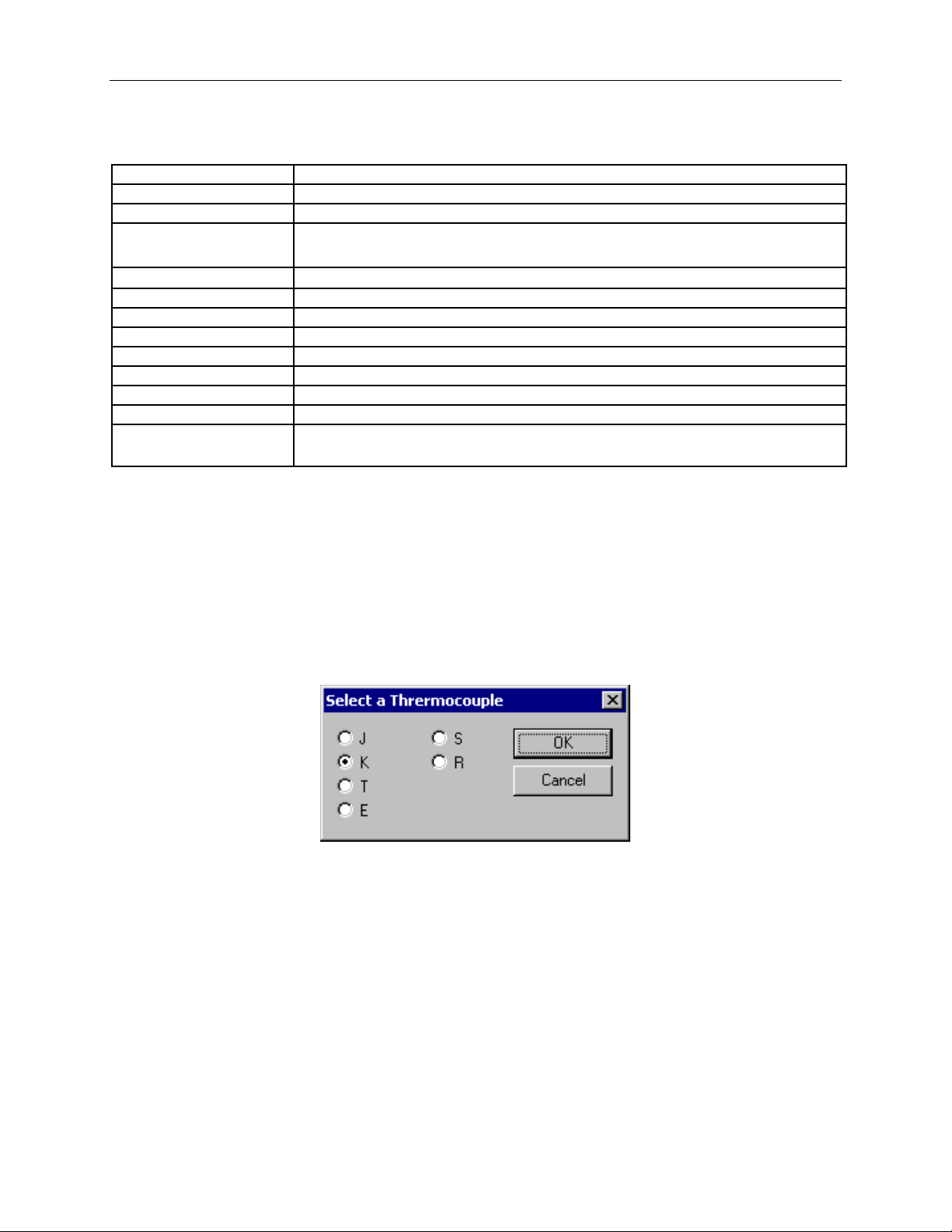
Connecting the OM-PL420 to the 4 - 20 ma Loop.
To connect t he 4 – 20 ma loop to the logger, use the connector provided. Make sure to connect the positive and
negative terminals correctly as shown in the figure below.
Page 29
OM-PL Series Data Logger Interface Software Version 2.5x Page 28 /29
Sample Point Capacity
21,500 points.
Alarms
Over and under alarm.
Calibration
Factory calibrated. User single point offset calibration is available through software.
Operating Temperature
-40°F to 150°F (-40°C to 65°C) using Lithium Battery.
Time Accuracy
+/-100ppm @75°F
Relative Humidity Range
0% to 95%RH non condensing
Input Current Range
0ma – 40ma
Current Resolution
0.01ma
Current Accuracy
+/- 0.05 ma
Dimensions
3’’ x 2.5" x 1.1’’ (7.6cm x 6.4cm x 2.8cm)
Weight
2.5 Oz (85g)
Power Source
9V Alkaline or Lithium battery.
Battery Life (average use)
42 Months using Lithiu m Battery.
OM-PL420 Specifica t ions
32°F to 140°F (0°C to 60°C) using Alkaline Battery.
21 Months using Alkaline Battery.
OM-PLTC: Thermocouple Te m pe rature Logger
The OM-PLTC i s a self-contained, precision instrument for recording the temperature of a thermocouple probe, and
the temperature of the internal sensor. The unit can be used with J, K, E, T, R and S type thermocouples. The OMPLTC can store up to 10,750 samples of thermocouple and internal sensor temperatures.
OM-PLTC Logging Setup
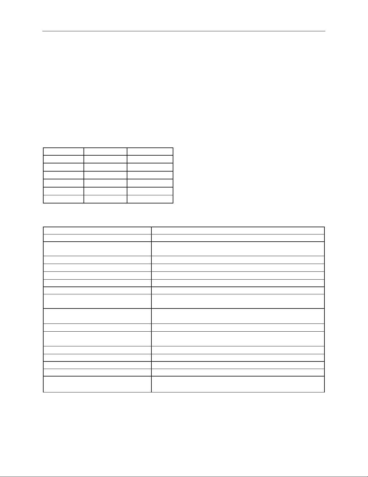
The OM-PLTC logger is setup to log like the rest of the OM-PL family. The setup procedure is described in the
Setting Up The Logger To Record Data. Before the main setup window pops up, the thermocouple selection window
is displayed.
The last selected thermocouple is the default. To keep the thermocouple the same, just click OK.
To select a new thermocouple type, click on the type you are using, then click OK.
Changing the thermocouple type invalidates the thermocouple alarm thresholds stored in the logger. This is
because each thermocouple uses slightly different constants for reference junction compensation. Changing
the thermocouple type may greatly offset the thermocouple alarm thresholds. Whenever you change the
thermocouple type, make sure to verify your thermocouple threshold settings using the Alarm Setup
Window. Changing the thermocouple type does no t affect the internal sensor alarm thresholds.
OM-PLTC Safety Precauti ons
The thermocouple logger is intended to measure both very low and very high temperatures. The OM-PLTC should
only be used by qualified personnel, trained in the safe operation of electronic test equipment. Please follow the
safety precautions below when operating the logger.
Page 30
OM-PL Series Data Logger Interface Software Version 2.5x Page 29 /29
Thermocouple
Min
Max
J
-110°F (-79°C)
1350°F (730°C)
K
-220°F (-140°C)
1900°F (1040°C)
E
-75°F (-59°C)
1040°F (560°C)
T
-235°F (-148°C)
660°F (350°C)
R
32°F (0°C)
2640°F (1450°C)
S
32°F (0°C)
2640°F (1450°C)
Sample Point Capacity
10,750 points of thermocouple and ambient temperature.
Alarms
Over and und er alarms for thermocouple and ambient temperature.
Calibration
Factory calibrated. User single point offset calibration is available
through software for both thermocouple and ambient temperatures.
Logger Operating Temperature
32°F to 140°F (0°C to 60°C)
Storage Temperature
-40°F to 170°F (-40°C to 77°C)
Real Time Clock Accuracy
+/-100ppm @75°F
Supported Thermocouples
J, K, E, T, R, S Software selectable.
Thermocouple Connector
Industry standard mini ature universal connector.
Supplied Probe
3ft FDA approved K type thermocouple probe. Probe temperature
range is -40°F to 400°F (-40°C to 204°C)
Thermocouple Sensor Accuracy
Thermocouple wire dependant. The supplied probe accuracy is +/-4°F
(2°C) or 0.75% of reading, whichever is greater.
Thermocouple Sensor Resolution
0.1°F (0.05°C)
Internal Sensor Temperature Accuracy
+/-2°F (1°C). For full accuracy allow a few minutes of thermal setting
after connecting the thermocouple to the logger.
Internal Sensor Temperature Resolution
0.1°F (0.05°C)
Dimensions
3’’ x 2.5" x 1.1’’ (7.6cm x 6.4cm x 2.8cm)
Weight
2.5 Oz (71g)
Power Source
9V Alkaline or Lithium battery (Not Included).
Battery Life (average use)
40 Months using Lithiu m Battery.
• As with any electrical device, working with high voltage is hazardous. Avoid connecting the
thermocouple to surfaces with high voltage levels. If such a connection is possible, disconnect the
thermocouple from the logger before connecting the logger to your computer. If the thermocouple
probe touches a high voltage surface while the logger is connected to your computer, permanent
damage to your computer may result.
• Do not touch the temperature probe when measuring excessively high or low temperatures.
• Do not attempt to measure temperatures beyond the specifications of the probe.
OM-PLTC Thermocouple Te m pe rature Ranges
The OM-PLTC logger supports the temperature ranges summarized in the table below. These specifications are for
the logger only. The probe you are using may have different specifications. Never attempt to measure temperatures
beyond the specifications of the probe.
OM-PLTC Specificati ons
20 Months using Alkaline Battery.
Page 31

WARRANTY/DISCLAIMER
OMEGA ENGINEERING, INC. warrants this unit to be free of defects in materials and workmanship for a
period of 13 months from date of purchase. OMEGA’s WARRANTY adds an additional one (1) month
grace period to the normal one (1) year product warranty to cover handling and shipping time. This
ensures that OMEGA’s customers receive maximum coverage on each product.
If the unit malfunctions, it must be returned to the factory for evaluation. OMEGA’s Customer Service
Department will issue an Authorized Return (AR) number immediately upon phone or written request.
Upon examination by OMEGA, if the unit is found to be defective, it will be repaired or replaced at no
charge. OMEGA’s WARRANTY does not apply to defects resulting from any action of the purchaser,
including but not limited to mishandling, improper interfacing, operation outside of design limits,
improper repair, or unauthorized modification. This WARRANTY is VOID if the unit shows evidence of
having been tampered with or shows evidence of having been damaged as a result of excessive corrosion;
or current, heat, moisture or vibration; improper specification; misapplication; misuse or other operating
conditions outside of OMEGA’s control. Components in which wear is not warranted, include but are not
limited to contact points, fuses, and triacs.
OMEGA is pleased to offer suggestions on the use of its various products. However,
OMEGA neither assumes responsibility for any omissions or errors nor assumes liability for
any damages that result from the use of its products in accordance with information provided
by OMEGA, either verbal or written. OMEGA warrants only that the parts manufactured by the
company will be as specified and free of defects. OMEGA MAKES NO OTHER WARRANTIES OR
REPRESENTATIONS OF ANY KIND WHATSOEVER, EXPRESSED OR IMPLIED, EXCEPT THAT OF
TITLE, AND ALL IMPLIED WARRANTIES INCLUDING ANY WARRANTY OF MERCHANTABILITY
AND FITNESS FOR A PARTICULAR PURPOSE ARE HEREBY DISCLAIMED. LIMITATION OF
LIABILITY: The remedies of purchaser set forth herein are exclusive, and the total liability of
OMEGA with respect to this order, whether based on contract, warranty, negligence,
indemnification, strict liability or otherwise, shall not exceed the purchase price of the
component upon which liability is based. In no event shall OMEGA be liable for
consequential, incidental or special damages.
CONDITIONS: Equipment sold by OMEGA is not intended to be used, nor shall it be used: (1) as a “Basic
Component” under 10 CFR 21 (NRC), used in or with any nuclear installation or activity; or (2) in medical
applications or used on humans. Should any Product(s) be used in or with any nuclear installation or
activity, medical application, used on humans, or misused in any way, OMEGA assumes no responsibility
as set forth in our basic WARRANTY/D ISCLAIMER language, and, additionally, purchaser will indemnify
OMEGA and hold OMEGA harmless from any liability or damage whatsoever arising out of the use of the
Product(s) in such a manner.
RETURN REQUESTS/INQUIRIES
Direct all warranty and repair requests/inquiries to the OMEGA Customer Service Department.
BEFORE RETURNING ANY PRODUCT(S) TO OMEGA, PURCHASER MUST OBTAIN AN AUTHORIZED
RETURN (AR) NUMBER FROM OMEGA’S CUSTOMER SERVICE DEPARTMENT (IN ORDER TO AVOID
PROCESSING DELAYS). The assigned AR number should then be marked on the outside of the return
package and on any correspondence.
The purchaser is responsible for shipping charges, freight, insurance and proper packaging to prevent
breakage in transit.
FOR WARRANTY RETURNS, please have the
following information available BEFORE contacting
OMEGA:
1. Purchase Order number under which the product
was PURCHASED,
2. Model and serial number of the product under
warranty, and
3. Repair instructions and/or specific problems
relative to the product.
OMEGA’s policy is to make running changes, not model changes, whenever an improvement is possible. This affords
our customers the latest in technology and engineering.
OMEGA is a registered trademark of OMEGA ENGINEERING, INC.
© Copyright 2015 OMEGA ENGINEERING, INC. All rights reserved. This document may not be copied, photocopied,
reproduced, translated, or reduced to any electronic medium or machine-readable form, in whole or in part, without the
prior written consent of OMEGA ENGINEERING, INC.
FOR NON-WARRANTY REPAIRS,
OMEGA for current repair charges. Have
the following information available BEFORE
contacting OMEGA:
1. Purchase Order number to cover the COST
of the repair,
2. Model and serial number of the product, and
3. Repair instructions and/or specific problems
relative to the product.
consult
Page 32

Where Do I Find Everything I Need for
Process Measurement and Control?
OMEGA…Of Course!
Shop online at omega.com
TEMPERATURE
MU
Thermocouple, RTD & Thermistor Probes, Connectors, Panels & Assemblies
MU
Wire: Thermocouple, RTD & Thermistor
MU
Calibrators & Ice Point References
MU
Recorders, Controllers & Process Monitors
MU
Infrared Pyrometers
PRESSURE, STRAIN AND FORCE
MU
Transducers & Strain Gages
MU
Load Cells & Pressure Gages
MU
Displacement Transducers
MU
Instrumentation & Accessories
FLOW/LEVEL
MU
Rotameters, Gas Mass Flowmeters & Flow Computers
MU
Air Velocity Indicators
MU
Turbine/Paddlewheel Systems
MU
Totalizers & Batch Controllers
SM
pH/CONDUCTIVITY
MU
pH Electrodes, Testers & Accessories
MU
Benchtop/Laboratory Meters
MU
Controllers, Calibrators, Simulators & Pumps
MU
Industrial pH & Conductivity Equipment
DATA ACQUISITION
MU
Data Acquisition & Engineering Software
MU
Communications-Based Acquisition Systems
MU
Plug-in Cards for Apple, IBM & Compatibles
MU
Data Logging Systems
MU
Recorders, Printers & Plotters
HEATERS
MU
Heating Cable
MU
Cartridge & Strip Heaters
MU
Immersion & Band Heaters
MU
Flexible Heaters
MU
Laboratory Heaters
ENVIRONMENTAL
MONITORING AND CONTROL
MU
Metering & Control Instrumentation
MU
Refractometers
MU
Pumps & Tubing
MU
Air, Soil & Water Monitors
MU
Industrial Water & Wastewater Treatment
MU
pH, Conductivity & Dissolved Oxygen Instruments
M5456/0315
 Loading...