

Page 1

Page 2

Page 3

Table of Contents
Preface
About this User's Guide ....................................................................................................................... 5
What you will lear n from this user's guide ......................................................................................................... 5
Conventio ns in this user's guide ......................................................................................................................... 5
Where to find more information ......................................................................................................................... 5
Chapter 1
Introducing the OM-NET-TC ................................................................................................................. 6
Ethernet interface ................................................................................................................................................ 6
Functional block diagram ................................................................................................................................... 6
Chapter 2
Installing the OM-NET-TC ..................................................................................................................... 7
Unpacking........................................................................................................................................................... 7
Installing the software ........................................................................................................................................ 7
Connecting the external power adapter .............................................................................................................. 7
Installing the hardware ....................................................................................................................................... 7
Configuri ng net wo rk s ett i ng s ............................................................................................................................. 8
Address mode settings ...................................................................................................................................................... 8
IP address settings ............................................................................................................................................................. 8
Connection code ............................................................................................................................................................... 8
Configuri ng the network r outer for co mmunication across network s ................................................................ 8
Calibrating the hardware..................................................................................................................................... 9
Factory calibration ............................................................................................................................................................ 9
Field calibration ................................................................................................................................................................ 9
Restoring factory default network settings ......................................................................................................... 9
Chapter 3
Functional Details ............................................................................................................................... 10
External components ........................................................................................................................................ 10
Screw terminals................................................................................................................................................................10
LED status indicators .......................................................................................................................................................11
RESET button ..................................................................................................................................................................11
Ethernet connector ...........................................................................................................................................................11
External power connector ................................................................................................................................................11
Signal connections ............................................................................................................................................ 11
TC input ...........................................................................................................................................................................11
Digital I/O ........................................................................................................................................................................12
Counter input ...................................................................................................................................................................15
Power output ....................................................................................................................................................................15
Ground .............................................................................................................................................................................15
Mechanical drawings ........................................................................................................................................ 16
DIN-rail compatible .........................................................................................................................................................18
Chapter 4
Specifications ...................................................................................................................................... 19
Thermocouple input .......................................................................................................................................... 19
Channel configurations ..................................................................................................................................... 20
Compatible thermocouples ............................................................................................................................... 20
Accuracy ........................................................................................................................................................... 20
Thermocouple measurement accuracy .............................................................................................................................20
Digital input/output........................................................................................................................................... 21
Temperature alarms .......................................................................................................................................... 22
3
Page 4

OM-NET-TC User's Guide
Counter ............................................................................................................................................................. 22
Memory ............................................................................................................................................................ 22
Power ................................................................................................................................................................ 23
Network ............................................................................................................................................................ 23
Ethernet connection .........................................................................................................................................................23
Network interface ............................................................................................................................................................23
Network factory default settings ......................................................................................................................................23
Network security ..............................................................................................................................................................24
LED displays and the factor y reset button ........................................................................................................ 24
Environment ..................................................................................................................................................... 24
Mechanical ....................................................................................................................................................... 24
Screw terminal connector ................................................................................................................................. 25
4
Page 5

About this User's Guide
What you will learn from this user's guide
This user's guide describes the Omega Engineering, Inc. OM-NET-TC data acquisition de vice and lists device
specifications.
Conventions in this use r's guide
For more information
Text presented in a box signifies ad ditional information and helpful hints related to the subject matter you are
reading.
Caution! Shaded caution statements present information to help you avoid injuring yourself and others,
damaging your hardware, or losing your data.
bold text is used for the names of objects on a sc reen, such as buttons, text boxes, and che ck boxes.
italic text is used for the names of manuals and help topic titles, and to emphasize a word or phrase.
Preface
Where to find more informati on
Additional information about OM-NET-TC hardware is available on our website at www.omega.com. You can
also contact Omega Engineering, Inc. by phone, fax, or email with specific questions.
5
Page 6
Chapter 1
Introducing the OM-NET-TC
The OM-NET-TC is an Ethernet-based thermocouple (TC) data acquisition device that provides the following
features:
Eight 24-bit differential TC inputs
TC channels field-to-host isolation
4 S/s per channel update rate
Type J, K, R, S, T, N, E, and B thermocouples supported, software-selectable per channel
Two integrated cold junction compensation (CJC) sensors; one per four TC inputs
Open thermocouple detection (OTD)
Eight individually-configurable digital I/O channels, isolated from TC channels
±24 mA drive capability
10/100 Ethernet interface
+5 V external power adapter (OM-NET-PS) included
Ethernet interface
The OM-NET-TC has a built-in 10/100 BASE-T auto-negotiat ion, high-speed communication port. You can
remotely access and configure your OM-NET-TC from anywhere o n the network. Only one compute r can
control the OM-NET-TC at one time. The networking protocols are TCP and UDP.
A unique media access control (MAC) address is assigned to each device at the factory. You configure the
Ethernet connection settings through software. The network name uses the format
xxxxxx are the lower six digits of the factory-assigned MAC address.
E-TC-xxxxxx, where
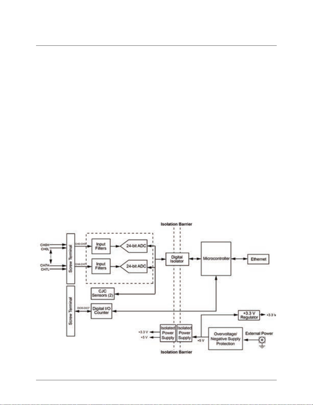
Functional block diagram
Device functions are illustrated in the block diagr am shown here:
Figure 1. Functional block diagram
6
Page 7

Chapter 2
Installing the OM-NET-TC
Unpacking
As with any electronic device, you should take care while handling to avoid damage from static
electricity. Before removing the board from its packaging, ground yourself using a wrist strap or by simply
touching the computer chassis or other grounded object to eliminate any stored static charge.
Installing the software
Refer to the Software User's G uid e for instruct ions on installing the software on the CD. This booklet is
available in PDF at www.omega.com/manuals/manualpdf/M4803.pdf
Install the software before you install your device
The driver needed to run the OM-NET-TC is installed with the software. Therefore , you need to install the
software package you plan to use before you install the hardware.
Connecting the external pow e r a dapter
Power to the OM-NET-TC is provided with the 5 volt, 1 amp external power adapter (OM-NET-PS). Connect
the adapter cord to the power connector on the OM-NET-TC, and plug the AC adapter into an electrical outlet.
.
Power LED turns on when 5 V power is supplied to the OM-NET-TC. If the voltage sup ply is less than
The
4.2 V or more than 5.6 V, the
Refer to Figure 3
on page 11 for the location of the Power LED.
POWER LED does not turn on.
Installing the hardware
The OM-NET-TC requires a TCP/IP and UDP connection to a network or computer. Use the standard Ethernet
cable provided to connect the OM-NET-TC to a 10Base-T or 100Base-TX compatible Ethernet port, hub, or
switch.
When connec ting the OM-NET-TC for the first time, make sure that you connect to a local network with DHCP
enabled.
If you are unsure whether you have access to a local network or that DHCP is enabled on that network, you
should use a direct connection to a Windows PC.
It may take a minute or two to detect the device and assign the address. The green
lower left of the Ethernet connector turns on when there is a valid Et hernet link, and blinks when network
activity is detected.
Once the OM-NET-TC is physically connected to the local network or PC, you can run the software such as
InstaCal to establish a connection. If a connection cannot be established, verify that the device is using the
default co nfiguration by following the instructio ns in the Restoring factor y de faul t ne twork settings
Once a connection is established and you can communicate to the device, you can change the configuration for
other netwo rk scenarios.
Link/activity LED on the
on page 9 .
7
Page 8

OM-NET-TC User's Guide Installing the OM-NET-TC
Configuring network se ttings
The following OM-NET-TC network settings are software-selectable. Only one user at a time can connect to
the OM-NET-TC to configure network options on the device. For typical local networks, the default settings are
recommended.
Address mode settings
The address mode setting determines whether the default IP parameters (IPv4 address, subnet mask, and
gateway) are assigned to the OM-NET-TC or an auto-addressing method is used to assign these parameters.
DHCP or link-local enabled (default)
If connected to a network with a DHCP server, the service automatically assigns an IP address to the device. If
the connected network does not have a DHCP server, the address stored in the default IP address is assigned.
If the OM-NET-TC is directly connected to a Windows PC or other host that supports link-local addressing, a
link-local address is assigned to the device. A link-local address is valid only for communications between the
OM-NET-TC and the device to which it is connected
DHCP Only
Enables configuration by a DHCP server, if one is available. The OM-NET-TC is assigned an IP addre ss shortly
after it is powered up and attached to the network.
Link Local Only
The OM-NET-TC is assigned a link-local IP address by the Windows PC or other host that supports link-local
addressing. A link-local add ress is valid only for communications between the OM-NET-TC and the device to
which it is connected.
Static
The default
IPv4 Address is manually configured on the OM-NET-TC.
IP address settings
The default settings of the following IP address are assigned to the OM-NET-TC when automatic addr essing is
disabled or not available (DHCP or Link Local for example)
IPv4 address – The IP address that is stored on the device. The default IPv4 address is 192.168.0.101.
Subnet mask – The Subnet mask that is store d on the OM-NET-TC . The subnet mask determines the
number of bits of the IP address that is used for the host portion of the address vs. the number of bits used
for the network portion. The default subnet mask is 255.255.255.000
Gateway – The gateway IP address that is st ored on the OM-NET-TC. The gateway address of the device
that bridges subnets within a network. The default gateway is 192.168.0.1
Connection code
The connection code is a number between 0 (default) and 999999999. You can change this number from its
default of 0 to prevent other users from connecting to and configuring the device. The device remains visible to
other users on the network, but connection by another us er is not allowed.
Configuring the network r out e r for communication across networks
In order to communicate with the OM-NET-TC from a computer connected to a different network – such as
over the Internet – you must change the network config uration of the network router .
In the following proced ure, the OM-NET-TC is installed on the host LAN, the computer is installed on the
client LAN, and it is assumed that you have you have successfully connected the device to a local network.
Caution! This procedure should only be performed by a network administrator or computer professional.
Incorrect settings can significantly disrupt a network.
8
Page 9

OM-NET-TC User's Guide Installing the OM-NET-TC
1. Determine the IP address of the device. If the address was assigned by DHCP, it is recommended you
change it to a static address by setting the default address to the address assigned and setting the device
network configuration to static.
2. Configure the firewall/router to forward incoming traffic to the following ports to the IP address assigned
to the device:
o UDP:54211 (discovery)
o TCP:54211 (commands)
3. On the computer connected to the client LAN, manually enter the WAN address of the host router, and
specify the ports that were forwarded to connect to the remote OM-NET-TC.
Calibrating the hardware
Factory calibration
Omega Engineering, Inc. performs the initial factory calibration. Contact Omega Engineering, Inc. for details
about how to return your device and have it calibrated to the factory specifications. The recommended
calibration interval is one year .
Field calibration
The OM-NET-TC also supports field calibration. as an alternative to returning the device for factory calibration.
The same recommended one-year calibration interval applies.
The following items are required to perform field calibration on an OM-NET-TC:
a precision voltage source
a voltmeter
Each AD C (two ADCs per device) is measured at seven points and a linear correction is calculated.
When prompted, enter the voltmeter reading to a precision of six decimal places.
Omega Engineering strongly recommends that you warm up the OM-NET-TC for at least 20 minutes prior to
performing field calibration.
Restoring factory default network settings
To reset the network configuration settings to the factory default values, co mple te the following steps:
1. Press and hold in the
twice and then turn off, indicating that network settings ha ve been restored to default values.
2. Release the button so the device continues startup with the default settings.
If the button is released before the two LEDs blink, the settings are not affected and the device starts up
normally.
Holding in the Reset button too long may cause the device to enter bootloader mode
Holding the Reset button in after the Power and Activity LEDs blink may cause the d e vice to enter firmware
update (bootloader) mode. In this mode both LEDs continuously blink. If this o ccurs, cycle the power to return
the device to normal operation.
If InstaCal is open when default settings are restored, click the Refresh Boards button on the InstaCal toolbar
to reflect the changes.
Reset button for at least four seconds until both the Power and Activity LEDs blink
9
Page 10

Functional Det ails
External components
The OM-NET-TC has the fol lowing external components:
Screw terminals
LED status indicators
Ethernet connector
External power connector
Factory reset button
Screw terminals
The OM-NET-TC screw terminals provide the following connections:
Chapter 3
Eight differential (
Eight digital I/O lines (
One counter input (
One voltage output (
Five digital grounds (
Signal locations are shown in Figure 2.
CH0H/CH0L to CH7H/CH7L) thermocouple inputs
DIO0 to DIO7)
CTR)
+VO)
GND) and one chassis ground (CHGND)
Figure 2. OM-NET-TC pinout
10
Page 11

OM-NET-TC User's Guide Functional Details
1
External power connector
4
Activity LED (bottom )
2
Ethernet connector with green Link/activity LED
(left) and yellow Speed LED (right)
5
Factory reset button
3
Power LED (top)
The remaining components are on the top edge of the enclosure; refer to Figure 3:
Figure 3. OM-NET-TC connectors, reset button, and status LEDs
LED status indicators
The OM-NET-TC has two LED indicators that indicate the status of power and host communications:
The
Power LED is on when external power between 4.2 V to 5.6 V is supplied.
This LED is off when the external power supply is not connected, or the input power is outside of the 4.2 V
to 5.6 V voltage range of the external supply, causing a power fault.
The OM-NET-TC has an onboard voltage s upervisory circuit that monit ors the 5 V external po wer supply.
The
Activity LED is on when a valid host connection is dete c te d.
This LED blinks when a command is received.
Both Power and Activity LEDs blink once when factory default settings are restored. Refer to
Restoring factory
default netwo rk se tt i ng s on page 9 for more information.
RESET button
Press and hold this button to restore the OM-NET-TC to its factory default network settings. Both Power and
Activity LEDs blink once when factory default settings are restored. Refer to Restoring factory default network
settings on page 9 for more information.
Ethernet connector
The OM-NET-TC has one 10/100 BASE-T, auto-negotiation, high-speed communication port. The port
connector is an RJ-45, eight-position connector. The Ethernet port accepts CAT-5 shielded or unshielded
twisted pair cable. The maximum communication distance without using a repeater is 100 meters.
External power connector
Connect the OM-NET-PS power supply to this connector. The power supply provides 5 VDC, 1 A power to the
OM-NET-TC.
Signal connections
TC input
A thermocouple consists of two dissimilar metals that are joined together at one end. When the junction of the
metals is heated or cooled, a voltage is produced that correlates to temperature.
The OM-NET-TC supports type J, K, S, R, B, E, T, N thermocouples.
When TCs are attached to conductive surfaces, the voltage differential between multiple TCs must remain
within ±1.8 V. For best results, use electrically insulated TCs when connected to electrically charged surfaces if
possible.
11
Page 12

OM-NET-TC User's Guide Functional Details
Caution! We strongly recommend that you ground yourself using a wrist strap before handling t he
thermocouple sensors.
Hardware compatibility
The OM-NET-TC is functionally equivalent to the OM-USB-TC. Universal library programs written for the
OM-USB-TC can be run wit h the OM-NET-TC.
Cold junction compensation (CJC)
Each group of four TC inputs has a high-resolution CJC sensor. When you connect the thermocouple sensor
leads to the sensor input channel, the d issimilar metals at the OM-NET-TC terminal blocks produce an
additional thermocouple junction. This junction creates a small voltage error component which mus t be
removed from the overall sensor measurement using a CJC technique.
The measured voltage includes both the thermocouple voltage and the cold junction voltage. To compensate for
the additional cold junction voltage, the OM-NET-TC subtracts the cold junction voltage from the
thermocouple voltage.
Increasing the thermocouple length
If you need to increase the length of your thermocouple, use the same type of TC wires to minimize the error
introduced by thermal EMFs.
Data linearization
After the CJC correction is performed on the measurement data, an on-board microcontroller automatically
linearizes the thermocouple measurement data using National Institute of Standards and Technology (NIST)
linearization coefficients for the selected thermocouple type.
The measurement data is then output as a 32-bit floating point value in the configure d format (voltage or
temperature).
Open-thermocouple detection (OTD)
The OM-NET-TC is equipped with OTD for all TC input channels. Any open-circuit condition at the TC sensor
is detected by the software. An open channel is detected by the use of a pull-up and pull-down resistors on the
thermocouple inputs. An open thermocouple condition forces the input differential voltage outside of the valid
thermocouple voltage range. The software recognizes this as an invalid reading, and flags the appropriate
channel. The software continues to sample all channels when OTD is detected.
Input leakage current
With OTD enabled, 65 nA (typical) of input leakage current is injected into the TC. This current can caus e an
error voltage to develop across the lead resistance of the TC that is indistinguishable from the thermocouple
voltage you are measuring. You can estimate this error voltage with the following formul a:
error voltage = resistance of the thermocoup le × 65 nA
To reduce the error, reduce the length of the TC to lower its resistance, or lower the AWG of the wire by using
a wire with a larger diameter. With open-thermocouple detection disabled, 1 nA (typical) of i nput leakage
current is injected into the TC.
Digital I/O
The OM-NET-TC has eight digital I/O channels t hat are electricall y isolated from the analog circuits. Each bit
is individually configurable for input or output. The di gita l I/O transfer rate is 5 kHz maximum for softwarepaced operation on a local network.
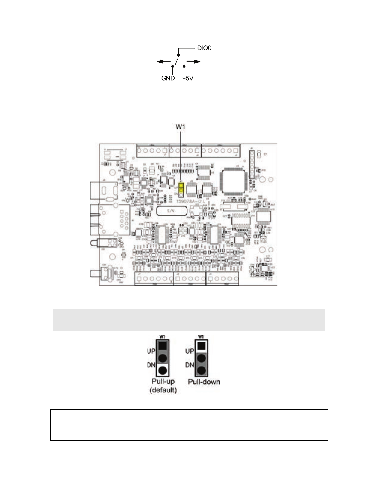
When you configure the di gi tal bits for input, you can use the OM-NET-TC digital I/O terminals to detect the
state of any TTL-level input. Refer to the schematic shown in Figure 4. If you set the switch to the +5V input,
DIO0 reads TRUE (1). If you move the switch to GND, DIO0 reads FALSE (0).
12
Page 13
OM-NET-TC User's Guide Functional Details
Figure 4. Schematic showing switch detection by digital channel DIO0
Pull-up/down configuration
All DIO channels are pulled high by default to 5 V through 47 kΩ resistors with jumper
(see Figure 5). Each jumper configures a digital port for pull-up or pull-down.
Figure 5. Pull-up/down jumper locations
W1 on the circuit board
Figure 6 below shows the jumper configured for pull-up and pull-down.
Caution! The discharge of static electricity can damage some electronic components. Take care when
removing the enclosure. Before touching the board, ground yours elf using a wrist strap or touch
the computer chassis or other grounded object to eliminate any stored static charge.
Figure 6. Pull-up/down jumper configurations, typical
More information about digital signal connections
For general information about d igital signal connections and digital I/O tec hniques, refer to the
OMB-DAQ-2400, OMB-DAQ-RACK, OM-NET, OM -USB, OM-WEB, and OM-WLS Series General Guide to
Signal Connections (available on our website at www.omega.com/manuals/manualpdf/M4830.pdf).
13
Page 14
OM-NET-TC User's Guide Functional Details
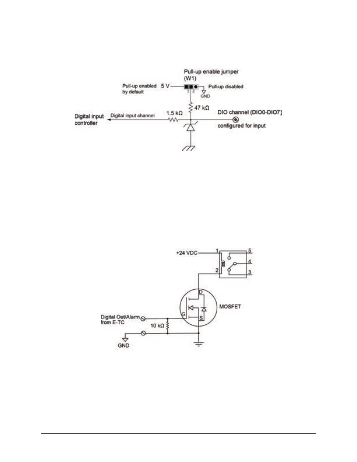
When confi gured for input, input voltage ranges of 0 V to 5 V are permitted, with thresholds of 0.8 V (low) and
2.0 V (high). A typical digital input connection is shown in Figure 7.
Figure 7. Digital input connection example
Temperature alarms
Optionally, you can configure e a c h d igital output as an alarm for each TC input. When an alarm is enabled, its
associated output line is driven to the appropriate state determined by the alarm options and input temperature.
You can also use the alarm outputs to control a device or application that indicate s when a temperature
threshold has been exceeded. Alarms can also indicate an OTC condition.
A digital output bit can be used to control a logic device needing up to 5 V @ 24 mA. If the device requires a
1
higher voltage/current, use an OM-NET-TC-controlled MOSFET
(user-provided) to control higher voltages
and currents.
Figure 8 shows a relay requiring 24 VDC @ 100 mA controlled by an OM-NET-TC digital output/alarm.
The MOSFET in this e xample is a relay and is rated for 14 amps and 50 volts DC.
Figure 8. Example of a digita l output /al ar m contr oll ing a rela y
The alarm configurations are stored in non-volatile memory and loaded at power up. Temperatures are
constantly converted on enabled channels and processed for alarm conditions regardless of the communications
connectivity.
1
Metal-oxide semiconductor, field-effect transistor that uses an induced electrical field to control current th ro ugh the device.
Either negative or pos itive gate voltages can be applied to control the current.
14
Page 15

OM-NET-TC User's Guide Functional Details
Alarm when input te mperature ≥ T1; reset alarm when input temperatur e < T2
Disabled, digital I/O line may be used for normal operation
The following table describes the OM-NET-TC alarm modes and settings.
Alarm input modes
Set independent temperat ure
thresholds T1 and T2 for each alarm.
Alarm error modes
Alarm output modes
Alarm when input te mperature ≤ T1; reset alarm when input temperatur e >T2
Alarm when input temperature is < T1 or > T2
Alarm on temperature reading only
Alarm on temperature reading or open thermocouple error
Alarm on open thermocouple error only
Enabled, active high output – DIO line goes high when alarm condition is met
Enabled, active low output – DIO line goes low when alarm condition is met
Counter input
The CTR terminal is a 32-bit event counter that can accept frequency inputs up to 10 MHz. The internal counter
increment s when the TTL levels transiti on from low to high.
Power output
The +VO termina l can output up to 10 mA maximum. You can use this terminal to supply power to external
devices or circuitry.
Caution! The +VO terminal is an output. Do not connect it to an external power supply or you may damage
the device and possibly the computer.
Ground
The digital ground (GND) terminals provide a common ground – isolated fro m TC inputs – for the digital and
counter channels and the
+VO terminal.
The chassis ground (
CHGND) terminal provide s a connection p oint for chassis ground. Connect this to a n
external grounding source.
15
Page 16
OM-NET-TC User's Guide Functional Details
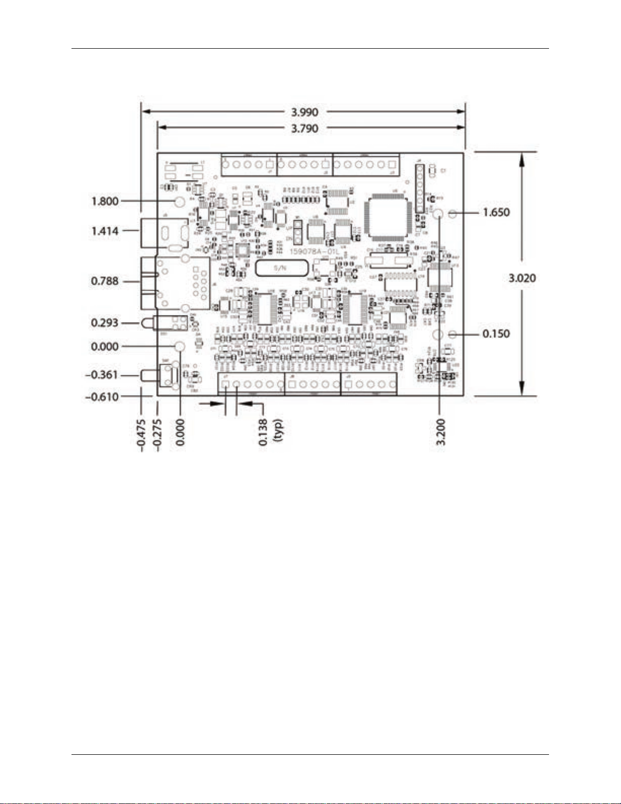
Mechanical drawings
Figure 9. OM-NET-TC device circuit board dimensio ns
16
Page 17
OM-NET-TC User's Guide Functional Details
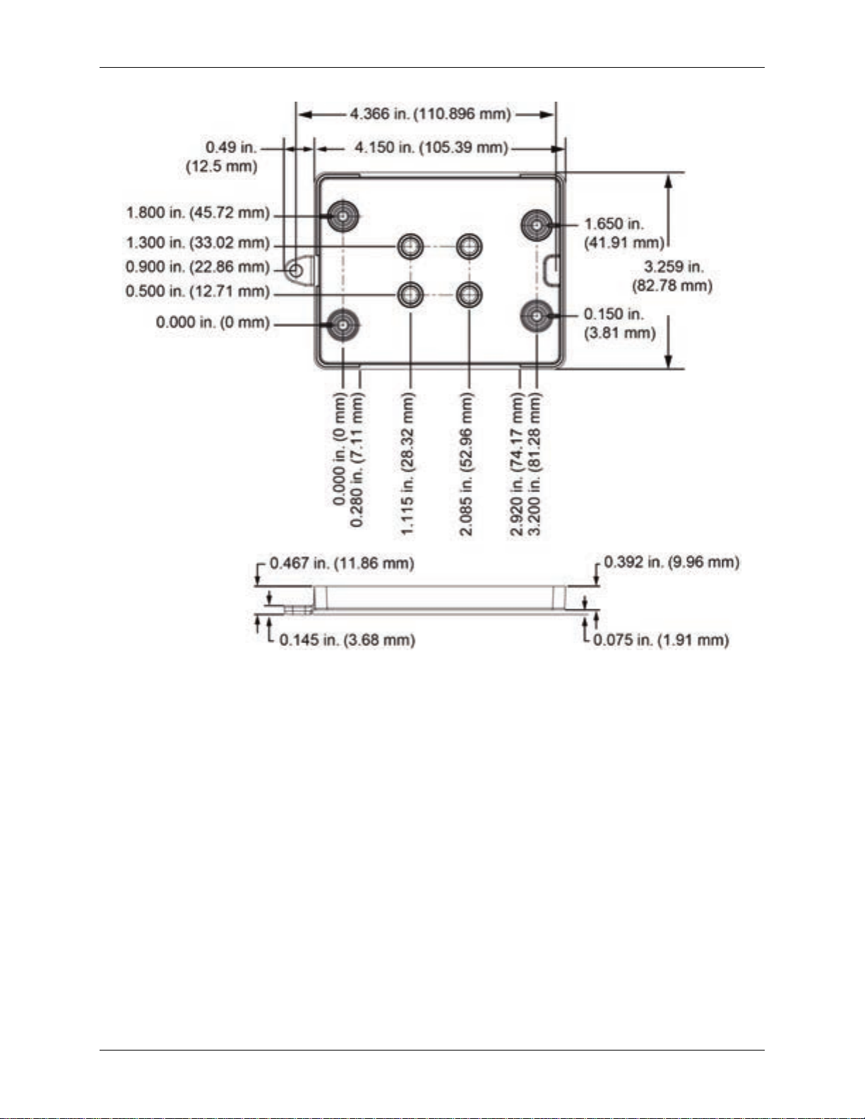
Figure 10. OM-NET-TC bottom enclosure dimensions
17
Page 18
OM-NET-TC User's Guide Functional Details
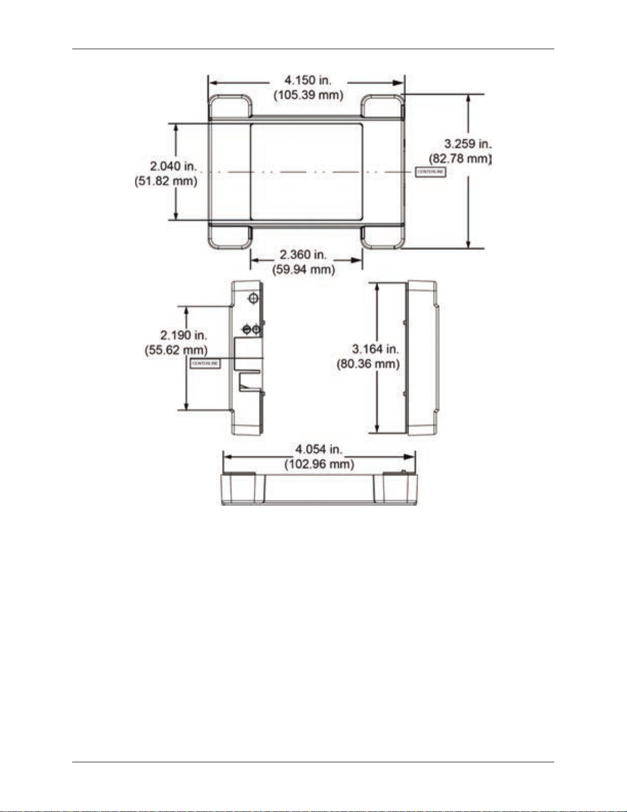
Figure 11. OM-NET-TC top enclosure dimensions
DIN-rail compatible
The OM-NET-TC can be mounted on a DIN rail using the OM-NET-DINRAILKIT accessory kit. Refer to our
website for more information.
18
Page 19

A/D converters
Delta-Sigma
ADC resolution
24 bits
Number of channels
8
Between any TCx channel and
digital/chassis ground.
Differential input voltage range
(Note 1)
Absolute maximum input
voltage
±25 V (power on)
±25 V (power off)
Differential input impedance
40 MΩ
disabled
Open thermocouple d etect
enabled
Common mode rejection
fIN = 50 Hz or 60 Hz
100 dB
Noise rejection
fIN = 50 Hz or 60 Hz
75 dB
Input bandwidth
10 Hz
Crosstalk
Between any two TCx inputs
–90 dB
Sample rate (Note 2)
4 Hz max (per channel)
Input noise
250 nV rms
Gain error
0.006 %
Offset error
3 µV
Thermocouple type J,K,T,E,N
0.09 °C
Thermocouple type R,S
0.11 °C
Thermocouple type B
0.13 °C
Warm-up time
20 minutes min
response time
±0.40 °C max
Recommended warm-up time
20 minutes min
Calibration interval
1 year (factory calibration)
Specifications
All specifications are subject to change without notice.
Typical for 25 °C unless otherwise specified.
Specifications in italic text are guaranteed by design.
Thermocouple input
Table 1. Thermocouple input specifications
Parameter Condition Specification
Chapter 4
Input isolation
Channel configuration Software-selectable to match sensor type
±0.128 V
Between any two TCx inputs
Open thermocouple d etect
Input current
Measurement sensitivity
(Note 3)
Open thermocouple d etect
1 second
500 VDC absolute max
1 nA
65 nA
CJC sensor accuracy 0 °C to 45 °C
Calibration method Factory
Note 1: Calibration is performed at ±70 mV.
Note 2: The enabled thermocouple inputs are continuously converted at the maximum A/D converter r ate. If channels
Note 3: Measurement sensitivi ty is the smallest change in temperat ure that can be detected.
±0.20 °C typ
are enabled and have an op en thermocouple connection the s ampl ing rate will be lower.
Page 20

OM-NET-TC User's Guide Specifications
J, K, S, R, B, E, T, or N
Type J.
J: –210 °C to 1200 °C
K: –270 °C to 1372 °C
R: –50 °C to 1768 °C
T: –270 °C to 400 °C
N: –270 °C to 1300 °C
E: –270 °C to 1000 °C
B: 0 °C to 1820 °C
–210
1.896
0.823
2.228
0.990
0
0.760
0.328
0.815
0.364
1200
0.717
0.324
1.336
0.585
0
0.787
0.334
0.848
0.377
1372
0.974
0.431
1.807
0.786
–50
2.144
0.711
2.566
1.053
250
1.595
0.528
1.888
0.775
–50
2.266
0.749
2.715
1.113
250
1.617
0.534
1.917
0.786
1768
0.631
0.148
1.579
0.584
250
1.934
0.453
2.552
0.977
1820
0.482
0.137
1.213
0.492
–200
1.700
0.742
1.987
0.884
0
0.752
0.327
0.806
0.360
1000
0.629
0.285
1.142
0.500
Channel configurations
Table 2. Channel configuration specifications
Sensor Category Condition Specification
Thermocouple
Note 4: Channel configuration is stored on EEPROM external to the isolated microcontroller by the firmware whenever
any item is modified. Modification is performed by commands issued over Ethernet from an external
application, and the configuration is made non-volatile through the use of the EEPROM.
The factory default configuration is
8 differential chann els (Note 4)
Compatible thermocouple s
Table 3. Compatible sensor type specifications
Parameter Specification
Thermocouple
S: –50 °C to 1768 °C
Accuracy
Thermocouple measurement accuracy
Table 4. Thermocouple accuracy specifications, including CJC measurement error (Note 5, Note 6)
All specifications are (±).
Sensor
Type
J
K
S
R
B
E
Sensor
Temperature (°C)
–210 2.196 0.938 2.578 1.141
1768 0.750 0.178 1.759 0.649
700 0.740 0.179 1.128 0.439
Accuracy Error
Maximum (°C),
15 °C to 35 °C
Accuracy Error
Typical (°C),
15 °C to 35 °C
Accuracy Error
Maximum (°C),
0 °C to 45 °C
Accuracy Error
Typical (°C),
0 °C to 45 °C
20
Page 21

OM-NET-TC User's Guide Specifications
–200
1.920
0.817
2.253
0.993
0
0.801
0.339
0.870
0.385
400
0.519
0.223
0.702
0.308
–200
2.125
0.876
2.518
1.101
0
0.857
0.351
0.940
0.412
1300
0.668
0.291
1.352
0.585
Digital type
5 V TTL input / CMOS output
Number of I/O
One port of 8 bits, shared with temperatur e alarms
Configuration
Each bit can be independently configured for input or output
Power on conditions
Power on reset is input mode, except when bits are configured to operate as alarms.
Pull-up/pull-down
configuration
The port has 47 kΩ resistors configurable as pull-up (default) or pull-down via internal
jumper W1.
Digital I/O transfer rate
(system paced)
Power on and reset state
All bits are input unless the temperature alarm functionality is enabled for them.
Input high voltage threshold
2.0 V min
Input high voltage limit
5.5 V absolute max
Input low voltage threshold
0.8 V max
0 V recommended min
3.76 V min (IOH = –24 mA)
0.44 V max (IOL = 24 mA)
Sensor
Type
T
N
Note 5: Thermocouple measurement accuracy specifications include polynomial linearization, cold-junction
Note 6: When thermocouples ar e attached to conductive surfaces, the voltage differential between multiple
Sensor
Temperature (°C)
compensation, and system noise. The accuracy specifications assume the device is operated within its enclosure
and has been warmed up for the recommended 20 minutes. Errors shown do not include inherent thermocouple
error. Contact your thermocouple supplier for details on the actual thermocouple accuracy error.
thermocouples must remain within ±1.8 V. For best results we recommend using electri cally insulated
thermocouples when possible.
Accuracy Error
Maximum (°C),
15 °C to 35 °C
Accuracy Error
Typical (°C),
15 °C to 35 °C
Accuracy Error
Maximum (°C),
0 °C to 45 °C
Digital input/output
Table 5. Digital input/output specifications
Parameter Specification
Accuracy Error
Typical (°C),
0 °C to 45 °C
100 to 5000 reads / writes per second, typical, on a local network (Note 7)
Input low voltage limit
Output high voltage
Output low voltage
Note 7: This is the typical throughput when the device and host are both connected by Ethernet to the same local
network. Throughput can vary significantly, and typical throughput is not guaranteed, if a wireless connection i s
involved or data is sent over the internet.
–0.5 V absolute min
4.4 V min (IOH = –50 µA)
0.1 V max (IOL = 50 µA)
21
Page 22

OM-NET-TC User's Guide Specifications
Number of alarms
8 (one per digital I/O line)
stored in non-volatile memory and loaded at power on.
T1 and T2 may be independently set for each alarm.
Alarm on temperature reading only
Alarm on open thermocouple error only
Disabled, digital I/O line may be used for normal operation
Enabled, active low output (DIO line goes low when alarm condition is met)
Alarm latency (Note 8)
1 second
Counter type
Event counter
Input type
Schmitt trigger; fixed 47.5 kΩ pull-down resistor
Resolution
32 bits
Schmitt trigger hysteresis
0.6 V min
1.7 V max
Input high voltage threshold
1.9 V min
3.6 V max
Input low voltage threshold
1.0 V min
2.3 V max
0 V recommended min
Input frequency
10 MHz max
High pulse width
50 ns min
Low pulse width
50 ns min
EEPROM
4,096 bytes
Temperature alarms
Table 6. Temperature alarm specifications
Parameter Specification
Each alarm controls it s as s ociated digital I/O line as an alarm output. When an alarm is
Alarm functionality
Alarm input modes
Alarm error modes
Alarm output modes
Note 8: Alarm settings are applied when changed and at power-on. Temperatures are constantly converted on enabled
channels and processed for alarm conditions regardless of the communications connectivity.
enabled, its associated I/O line is set to output and driven to the appropriate state
determined by the alarm options and input temperature. The alarm configurations are
Alarm when input te mperature ≥ T1, reset alarm when input temperature < T2
Alarm when input te mperature ≤ T1, reset alarm when input temperature >T2
Alarm when input temperature is < T1 or > T2
Alarm on temperature read ing or open thermocouple error
Enabled, active high output (DIO line goes high when alarm condition is met)
Counter
Parameter Specification
Number of channels 1
Input high voltage limit 5.5 V absolute max
Input low voltage limit –0.5 V absolute min
Memory
Table 7. Counter specifications
Table 8. Memory specifications
Parameter Specification
22
Page 23

OM-NET-TC User's Guide Specifications
External power supply
5 V ±5% required
5 V, 1 A supply provided (PS-5V1AEPS)
Supply current
Quiescent current
177 mA typical (Note 9)
supplied AC adapter is used
User output current
Available at +VO terminal
10 mA max
Isolation
Measurement system to chassis ground
500 VDC min
10 Base-T
Communication rates
10/100 Mbps, auto-negotiated
Connector
RJ-45, 8 position
Cable length
100 meters (328 feet) max
Additional parameters
HP Auto-MDIX support
Protocols used
TCP (IPv4 only) and UDP
TCP: 54211 (commands)
Network IP configuration
DHCP + link-local, DHCP, static, link-local
Network name
E-TC-xxxxxx
xxxxxx
Network name publication
By NBNS; responds to b-node broadcasts, therefore only available on the local subnet
Factory default IP address
192.168.0.101
Factory default subnet mask
255.255.255.0
Factory default Gateway
192.168.0.1
Factory default DHCP
setting
Power
Table 9. Power specifications
Parameter Conditions Specification
User output voltage range Available at +VO terminal 4.40 V min to 5.25 V max; assumes
Note 9: This is the total quiescen t current requirement for the device t hat includes the LEDs. This value does not
include any potential loading of the digita l I/O bits or +VO terminal.
Network
Ethernet connection
Table 10. Ethernet connection specifi cations
Parameter Specification
Ethernet type
100 Base-TX
Network interface
Table 11. Factory default specific atio ns
Parameter Specification
UDP: 54211 (discovery)
Network ports used
UDP: 6234 (bootloa de r onl y)
Network factory default settings
Table 12. Factory default specific atio ns
Parameter Specification
DHCP + link-local enabled
, where
are the lower 6 digits of the device MAC address
23
Page 24

OM-NET-TC User's Guide Specifications
TCP sockets are not opened unless application sends the correct PIN connection
code; stored in non-volatile memory; may be changed by user; default value i s 0000
Number of concurrent sessions
1
Vulnerabilities
TCP Sequence Number Approximation Vulnerability
On: 4.2 V < V
< 5.6 V
Power and Activity LEDs blink continuously in firmware update mode
Power and Activity LEDs blink continuously in firmware update mode
Left (green): Link/activity indicator; on when there is a valid Ethernet link, and
Right (yellow): Speed indicator; on for 100 Mbps , off for 10 Mbps or no link.
Resets network and alar m configuration settings to factory default values.
constantly. The device may be returned to normal operation by cycling the power.
Operating temperature range
0 °C to 55 °C
Storage temperature range
–40 °C to 85 °C
Humidity
0 °C to 90% non-condensing
Dimensions (L × W × H)
117.9 × 82.8 × 29.0 mm (4.64 × 3.26 × 1.14 in.)
Network security
Table 13. Factory default specific atio ns
Parameter Specification
Security implementation
LED displays and the factory reset button
Table 14. LED and button configurations
Parameter Specification
Power LED (top)
Activity LED (bottom)
Ethernet connector LEDS
Off: V
On: A valid host connection is established.
Blinks: A command is received.
blinks when network activity is detected.
< 4.2 V, V
ext
ext
> 5.6 V (p ower fault)
ext
Press and ho ld for 4 seconds. The Power and Activity LEDs will both blink twice
Factory reset button
Holding the reset button at power on forces the device into firmware update mode
Environment
Table 15. Environmental speci ficat ion s
Parameter Specification
Mechanical
Parameter Specification
and turn off to indicate that network settings have been restored to default values.
Release the button to allow the device to reset and use the default settings.
If the reset button is released before the two LEDs blink, set tings are not affected.
in case of a failed firmware update. In this mode, both LEDs b lin k together
Table 16. Mechanical specific ation s
24
Page 25

OM-NET-TC User's Guide Specifications
Connector type
Screw terminal
Pin
Signal Name
Pin Description
Pin
Signal Name
Pin Description
1
CH0H
CH0 sensor input (+)
17
DIO0
DIO channel 0
2
CH0L
CH0 sensor input (–)
18
DIO1
DIO channel 1
3
CH1H
CH1 sensor input (+)
19
DIO2
DIO channel 2
4
CH1L
CH1 sensor input (–)
20
DIO3
DIO channel 3
5
CH2H
CH2 sensor input (+)
21
GND
Digital ground
6
CH2L
CH2 sensor input (–)
22
DIO4
DIO channel 4
7
CH3H
CH3 sensor input (+)
23
DIO5
DIO channel 5
8
CH3L
CH3 sensor input (–)
24
DIO6
DIO channel 6
9
CH4H
CH4 sensor input (+)
25
DIO7
DIO channel 7
10
CH4L
CH4 sensor input (–)
26
+VO
User voltage output
11
CH5H
CH5 sensor input (+)
27
GND
Digital ground
12
CH5L
CH5 sensor input (–)
28
GND
Digital ground
13
CH6H
CH6 sensor input (+)
29
GND
Digital ground
14
CH6L
CH6 sensor input (–)
30
CTR
Counter input
15
CH7H
CH7 sensor input (+)
31
GND
Digital ground
16
CH7L
CH7 sensor input (–)
32
CHGND
Chassis ground
Screw terminal connector
Table 17. Screw terminal connector specifications
Parameter Specification
Wire gauge range 16 AWG to 30 AWG
Table 18. Screw terminal pinout
25
Page 26

Page 27

 Loading...