

Page 1
Page 2

Page 3

Table of Contents
Preface
About this User's Guide ....................................................................................................................... 5
What you will lear n from this user's guide ......................................................................................................... 5
Conventio ns in this user's guide ......................................................................................................................... 5
Chapter 1
Introducing the OM-LGR-5329 ............................................................................................................. 6
OM-LGR-5329 block diagram ........................................................................................................................... 7
Chapter 2
Getting Started with the OM-LGR-5329 ............................................................................................... 8
Unpacking t he OM-LGR-5329 ........................................................................................................................... 8
What comes with your OM-LGR-5329 shipment? ............................................................................................. 8
Hardware .......................................................................................................................................................................... 8
Installing the software ........................................................................................................................................ 9
Installing the hardware ....................................................................................................................................... 9
Providing power to the OM-LGR-5329 ............................................................................................................................ 9
Connecting the OM-LGR-5329 to your system ................................................................................................................ 9
Chapter 3
Functional Details ............................................................................................................................... 10
OM-LGR-5329 external components ............................................................................................................... 10
Buttons and LEDs (top of case) .......................................................................................................................................11
Screw terminals and LED in dicators ................................................................................................................................13
Analog input terminals ..................................................................................................................................... 14
Trigger te rminals .............................................................................................................................................. 15
External digital trigger .....................................................................................................................................................15
External analog trigger (single-channel) ..........................................................................................................................15
Multichannel trigger ........................................................................................................................................................16
Digital-pattern trigger ......................................................................................................................................................20
Digital input and output terminals .................................................................................................................... 20
Counter input terminals and modes .................................................................................................................. 20
Encoder mode ..................................................................................................................................................................21
Counter mode ...................................................................................................................................................................22
Period measurement mode ...............................................................................................................................................23
Pulse width measurement mode .......................................................................................................................................23
Timing measurement mode ..............................................................................................................................................23
Debounce mode ...............................................................................................................................................................23
Trigger after stable mod e .................................................................................................................................................24
Trigger before stable mode ..............................................................................................................................................24
Debounce mode comparisons ..........................................................................................................................................25
Chapter 4
Specifications ...................................................................................................................................... 27
Analog input ..................................................................................................................................................... 27
Analog input calibration ................................................................................................................................... 28
External clock input .......................................................................................................................................... 28
Input sequencer ................................................................................................................................................. 28
Triggering ......................................................................................................................................................... 29
External analog trigger ..................................................................................................................................... 29
Digital input ...................................................................................................................................................... 30
Digital output .................................................................................................................................................... 30
Fault tolerance .................................................................................................................................................. 30
3
Page 4

OM-LGR-5329 User's Guide
Counters ............................................................................................................................................................ 31
Device configuration ........................................................................................................................................ 31
Controls/indicators............................................................................................................................................ 32
Data memor y .................................................................................................................................................... 32
Power ................................................................................................................................................................ 32
Chassis ground .................................................................................................................................................. 33
USB specifications ........................................................................................................................................... 33
Environmental .................................................................................................................................................. 33
Mechanical ....................................................................................................................................................... 33
Screw terminal connector type ......................................................................................................................... 33
Screw terminal pin out .....................................................................................................................................................34
4
Page 5

Preface
About this User's Guide
What you will learn from this user's guide
This user's guide explain s how to install, and use the OM-LGR-5329 so that you get the most out of its USB
data acquisition features.
This user's guide also refers you to re la te d documents available on our web site, and to technical support
resources.
Conventions in this user's guide
For more information on …
Text presented in a bo x signifies additional information and helpful hints related to the subject matter you are
reading.
Caution! Shaded caution statements present information to help you avoid injuring yourself and others,
damaging your hardware, or losing your data.
<#:#> Angle brackets that enclose numbers separated by a colon signify a range of numbers, such as those assigned
to registers, bit settings, etc.
bold text Bold text is used for the names of objects on the screen, such as buttons, text boxes, and check boxes. For
example:
1. Insert the disk or CD and click the OK button.
italic text Italic text is used for the names of manuals and help topic titles, and to emphasize a word or phrase. For
example:
■ The software installation procedure is explained in the DAQLog So f tware User’s Guide.
■ Never touch the exposed pins or circuit connections on the board.
5
Page 6

Chapter 1
Introducing the OM-LGR-5329
This user's guide contain s all of the information you ne ed to connect the OM-LGR-5329 to your computer and
to the signals you want to measure and log.
®
The OM-LGR-5329 is a USB 2.0 full-speed device supported under popular Microsoft
systems. The OM-LGR-5329 is compatible with both USB 1.1 and USB 2.0 ports.
With a multiplexed 16-bit A/D converter and a maximum sampling rate of 200 kS/s for all analog i nput
channels, the OM-LGR-5329 can sample:
Up to 16 single-ended analog inputs
Up to eight differential analog inputs
In ranges of ±30 V, ±10 V, ±5 V, ±1 V
You can start an analog input scan by:
Windows® operating
Pressing the
Configuri ng an external digital trigger
Configuri ng an external analo g trigger
Configuri ng a multichannel analog trigger
Configuri ng a digital pattern trigger
Pressing the
The OM-LGR-5329 also has 16 isolated digital input connections (PLC thresho lds with 28 V tolerance) that
you can configure to detect and log events based on change of state or pattern recognition. The device provides
500 V of isolation between the digital inputs and the host P C , analog input s, and counter inputs.
The OM-LGR-5329's single digital output is a 500 V alarm output implemented as a single Form C relay. You
can configure the relay to energize when the trigger condition is met and data is being recorded.
The OM-LGR-5329's four counter channels support the following counter modes:
Counter (general event counting)
Period counting
Pulse width c ounting
Edge-to-edge timing
1X, 2X, and 4X encoder counting.
Up/down counting
You can use the Modulo N number and mode with all of the counter modes listed to determine how the counter
behaves when it reaches the modulo number you set.
You can configure each counter channel in encoder mode for single-ended or differential mode using an
external switch.
START button
TRIG button to manually override a configured trigger
The device saves data to and retrieves data from a Secure Digital (SD) or Secure Digital High Capacity (SDHC)
memory card. The OM-LGR-5329 requires 9–30 V of external power.
6
Page 7
OM-LGR-5329 User's Guide Introducing the OM-LGR-5329
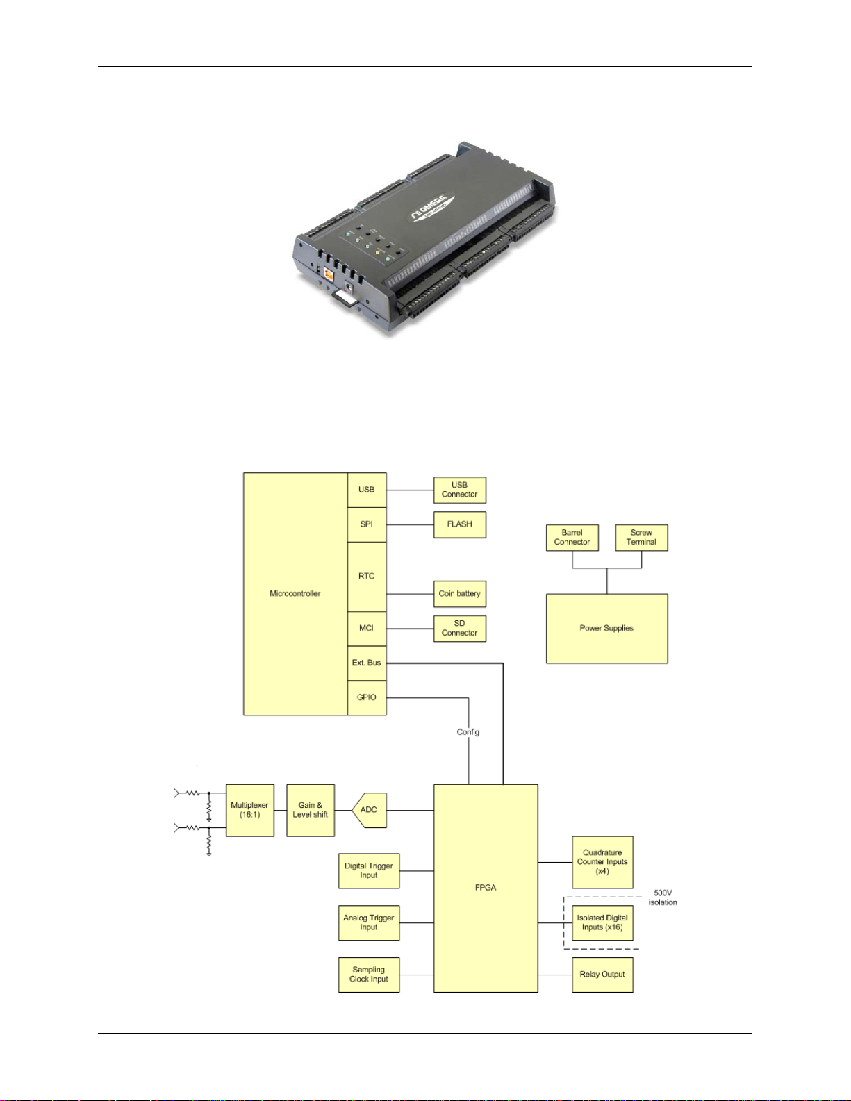
The OM-LGR-5329 is shown below. Use the two sets of screw terminals on the OM-LGR-5329 to make all I/O
connections.
For information on the features of the DAQLog software incl ud ed with yo ur OM-LGR-5329, refer to the
DAQLog Software User’s Guide that shipped with your device.
OM-LGR-5329 block diagram
Figure 1 shows a simplified block diagram of the OM-LGR-5329. This device provides all of the functional
elements shown in the figure.
Figure 1. OM-LGR-5329 functional block diagram
7
Page 8
Chapter 2
Getting Started with the OM-LGR-5329
This document explains how to unpack, connect, and use the OM-LGR-5329 to perform analog input scans,
digital input scans, and counter operations.
Unpacking the OM-LGR-5329
As with any electronic device, you should take care while handling to avoid damage from static
electricity. Before removing the OM-LGR-5329 from its packa ging, ground yourself using a wrist strap, or by
simply touching the computer chassis or other ground ed object to el iminate any stored static charge.
If your OM-LGR-5329 is damaged, notify Omega Engineering immediately by phone, fax, o r e-mail.
What comes with your OM-LGR-5329 shipment?
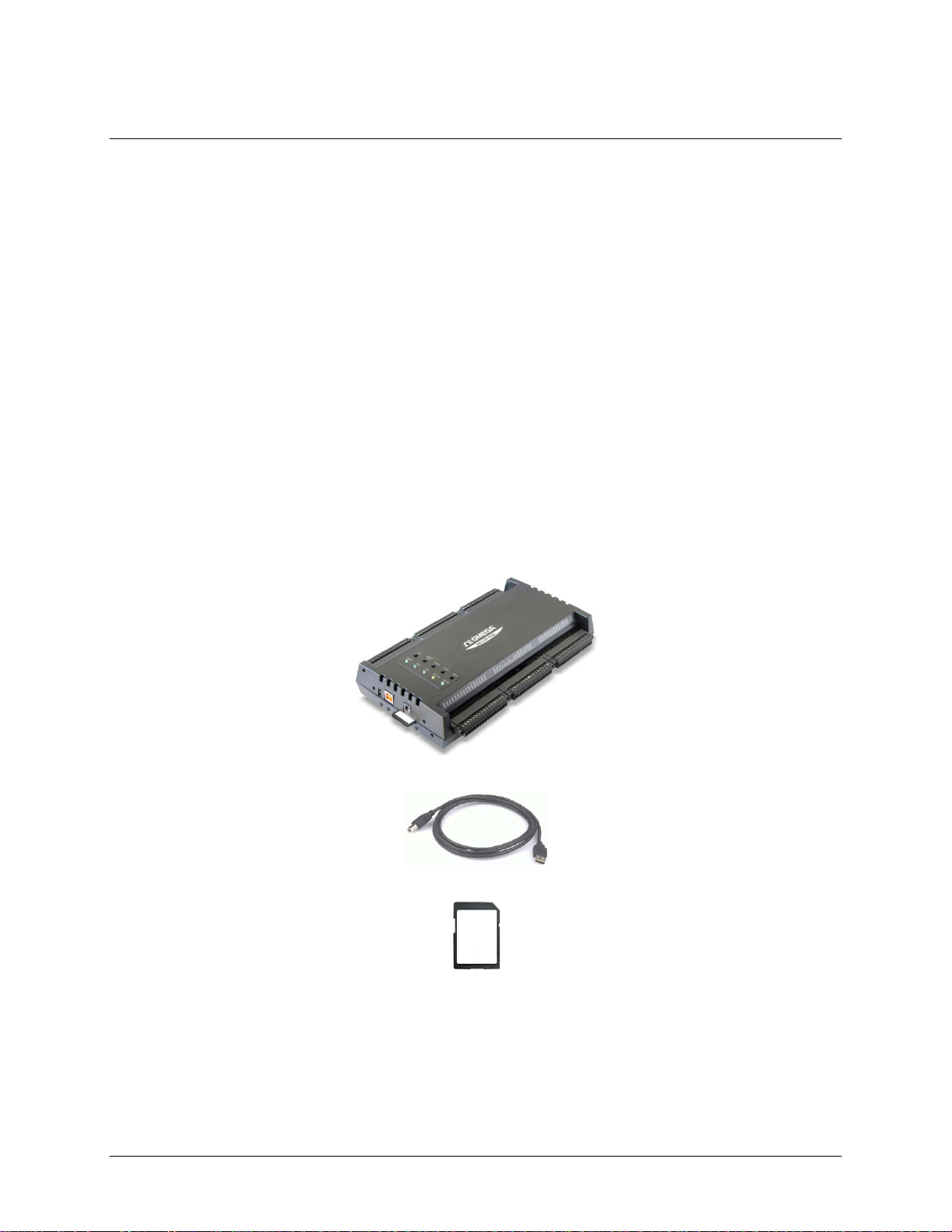
As you unpack your OM-LGR-5329, ve rify that the foll owing components are incl uded.
Hardware
OM-LGR-5329
USB cable (2-meter length)
SD card
9 V, 1 A external power supply for use when OM-LGR-5329 is not powered through the screw terminals
8
Page 9

OM-LGR-5329 User's Guide Getting Started with the OM-LGR-5329
Installing the software
Refer to the DAQLog Software User’s Guide for instructions on installing and using the DAQLog software.
This guide i s available in PDF at
www.omega.com/manuals/.
Installing the hardware
Follow these steps to provide power to the OM-LGR-5329 and connect it to a USB port on your host computer.
Providing power to the OM-LGR-5329
To power the OM-LGR-5329 from its screw terminals, connect the PWR+ terminal to the positive lead of
your power source, and the
that meets the power specifications of the OM-LGR-5329.
To power the OM-LGR-5329 from an external power source, using the power connector , connect the 9 V,
1 A external power supply to the external power
into an electrical outlet.
Always provide power to the OM-LGR-5329 before connecting its USB cable to the computer
Connect the external power cable to the OM-LGR-5329 before connecting the USB cable to the computer. Thi s
allows the OM-LGR-5329 to inform the host computer (when the USB cable is connected) that the device
requires minimal power from the computer’s USB port.
PWR- terminal to the negative lead of the power source. Use a power source
connector (see Figure 3 on page 10), and plug the adapter
Connecting the OM-LGR-5329 to your system
To connect t he OM-LGR-5329 to your system, turn the computer on, and connect a USB cable fro m the OMLGR-5329's USB connector (see Figure 3 on page 10) to either a USB port on the computer or an external USB
hub connected to the computer.
When you connect the OM-LGR-5329 for the first time, a
is detected. When the message clo ses, the installation is complete.
Found New Hardware message opens as the device
9
 Loading...