

Page 1
www.omega.com
e-mail: [email protected]
User’s Guide
OME-PIO-DA16/DA8/DA4
PCI-Bus
Analog Output Board
Hardware Manual
Shop online at
Page 2

Servicing North America:
USA: One Omega Drive, P.O. Box 4047
ISO 9001 Certified Stamford CT 06907-0047
TEL: (203) 359-1660 FAX: (203) 359-7700
e-mail: [email protected]
Canada: 976 Bergar
Laval (Quebec) H7L 5A1, Canada
TEL: (514) 856-6928 FAX: (514) 856-6886
e-mail: [email protected]
For immediate technical or application assistance:
USA and Canada: Sales Service: 1-800-826-6342 / 1-800-TC-OMEGA
®
Customer Service: 1-800-622-2378 / 1-800-622-BEST
®
Engineering Service: 1-800-872-9436 / 1-800-USA-WHEN
®
TELEX: 996404 EASYLINK: 62968934 CABLE: OMEGA
Mexico: En Espan˜ ol: (001) 203-359-7803 e-mail: [email protected]
FAX: (001) 203-359-7807 [email protected]
Servicing Europe:
Benelux: Postbus 8034, 1180 LA Amstelveen, The Netherlands
TEL: +31 (0)20 3472121 FAX: +31 (0)20 6434643
Toll Free in Benelux: 0800 0993344
e-mail: [email protected]
Czech Republic: Frystatska 184, 733 01 Karviná, Czech Republic
France: 11, rue Jacques Cartier, 78280 Guyancourt, France
TEL: +33 (0)1 61 37 29 00 FAX: +33 (0)1 30 57 54 27
Toll Free in France: 0800 466 342
e-mail: [email protected]
Germany/Austria: Daimlerstrasse 26, D-75392 Deckenpfronn, Germany
TEL: +49 (0)7056 9398-0 FAX: +49 (0)7056 9398-29
Toll Free in Germany: 0800 639 7678
e-mail: [email protected]
United Kingdom: One Omega Drive, River Bend Technology Centre
ISO 9002 Certified Northbank, Irlam, Manchester
M44 5BD United Kingdom
TEL: +44 (0)161 777 6611 FAX: +44 (0)161 777 6622
Toll Free in United Kingdom: 0800-488-488
e-mail: [email protected]
OMEGAnet®Online Service Internet e-mail
www.omega.com [email protected]
It is the policy of OMEGA to comply with all worldwide safety and EMC/EMI regulations that
apply. OMEGA is constantly pursuing certification of its products to the European New Approach
Directives. OMEGA will add the CE mark to every appropriate device upon certification.
The information contained in this document is believed to be correct, but OMEGA Engineering, Inc. accepts
no liability for any errors it contains, and reserves the right to alter specifications without notice.
WARNING: These products are not designed for use in, and should not be used for, patient-connected applications.
Page 3

OME-PIO-DA16/DA8/DA4
User’s Manual
OME-PIO-DA16/8/4 User’s Manual (Ver. 2.1,Nov /2003) ----- 1
Page 4

Tables of Contents
1. INTRODUCTION...........................................................................................................................3
1.1 FEATURES .................................................................................................................................... 3
1.2 SPECIFICATIONS ...........................................................................................................................4
1.3 ORDER DESCRIPTION....................................................................................................................5
1.4 PCI DATA ACQUISITION FAMILY ................................................................................................. 5
1.5 PRODUCT CHECK LIST..................................................................................................................6
2. HARDWARE CONFIGURATION...............................................................................................7
2.1 BOARD LAYOUT ........................................................................................................................... 7
2.2 COUNTER ARCHITECTURE ............................................................................................................8
2.3 INTERRUPT OPERATION ................................................................................................................9
2.4 D/I/O BLOCK DIAGRAM .............................................................................................................16
2.5 D/A ARCHITECTURE...................................................................................................................19
2.6 D/A CONVERT OPERATION ........................................................................................................ 20
2.7 THE CONNECTORS......................................................................................................................29
2.8 DAUGHTER BOARDS................................................................................................................... 31
3. I/O CONTROL REGISTER ........................................................................................................36
3.1 HOW TO FIND THE I/O ADDRESS ................................................................................................36
3.2 THE ASSIGNMENT OF I/O ADDRESS.............................................................................................41
3.3 THE I/O ADDRESS MAP ..............................................................................................................42
4. DEMO PROGRAM ......................................................................................................................50
4.1 PIO_PISO..................................................................................................................................52
4.2 DEMO1 .....................................................................................................................................54
4.3 DEMO2 .....................................................................................................................................55
4.4 DEMO3 .....................................................................................................................................56
4.5 DEMO5 .....................................................................................................................................58
4.6 DEMO8 .....................................................................................................................................60
4.7 DEMO9 .....................................................................................................................................61
OME-PIO-DA16/8/4 User’s Manual (Ver. 2.1,Nov /2003) ----- 2
Page 5

1. INTRODUCTION
The OME-PIO-DA16, OME-PIO-DA8 and OME-PIO-DA4 are multi-channel
D/A boards for the PCI bus for IBM or compatible PC.
The OME-PIO-DA16/8/4 offers 16/8/4 channels double-buffered analog output.
The output range may be configured in different ranges: ±10V, ±5V, 0~10V, 0~5V
voltage output or 4~20mA, 0~20mA current loop sink.
The innovative design eliminates several drawbacks of the conventional D/A
boards. For examples: 1. designed without jumpers and without trim-pot. 2. The
calibration is performed under software control eliminating manual trim-pot
adjustments. The calibration data is stored in EEPROM. 3. Each channel can be
selected as voltage or current output. 4. High channel count output can be
implemented in half size.
Note: This card need ±12V power supply (usually found in PC).
1.1 Features
• PCI bus
• 16/8/4 channels, 14-bit analog output
• Unipolar or bipolar outputs available from each converter
• Output type (Unipolar or bipolar) and output range ( 0~5V, ±5V, 0~10V, ±10V)
can be software programmable
• 4~20mA or 0~20mA current sink to ground for each converter
• Two pacer timer interrupt source
• Double-buffered D/A latches
• Software calibration
• 16 channels of DI, 16 channels of DO
• SMD, short card
• One D-Sub connector, two 20-pin flat cable connectors
• Connects directly to OME-DB-16P, OME-DB-16R, OME-DB-24C, OME-DB-
24PR and OME-DB-24POR
• Automatically detected by Windows 95/98/2000/XP
• No base address or IRQ jumper need to set
OME-PIO-DA16/8/4 User’s Manual (Ver. 2.1,Nov /2003) ----- 3
Page 6

1.2 Specifications
Digital Inputs/Outputs
• All inputs/outputs are TTL compatible
• Logic high Voltage VIH: 2.4V(Min.)
• Logic low Voltage VIL: 0.8V(Max.)
• Sink current IOL: 8mA(Max.)
• Source current IOH: 0.4mA(Max.)
Analog Outputs
• D/A converter: Quad 14 bits MDAC
• Channels: 16/8/4 independent
• Resolution: 14 bits
• Type: double-buffered, multiplying
• Integral linearity: 0.006% FSR (typical)
• Differential linearity: 0.006% FSR (typical)
Voltage Output Range:
• Unipolar: 0~5V or 0~10V
• Bipolar: ±10V or ±5V
• Current drive: ±5mA
• Absolute accuracy : 0.01% FSR (typical)
Current Output Range:
• 0~20mA or 4~20mA
• Absolute accuracy: 0.1% FSR (typical)
• Excitation voltage range: +7V to +40V dc
Power Consumption:
• OME-PIO-DA4: +5VDC @ 600mA
• OME-PIO-DA8: +5VDC @ 800mA
• OME-PIO-DA16: +5VDC @ 1400mA
Environmental:
• Operating Temp.: 0~60°C
• Storage Temp.: -20°C~80°C
• Humidity : 0~90% non-condensing
Dimension:
• 180 mm × 115mm
OME-PIO-DA16/8/4 User’s Manual (Ver. 2.1,Nov /2003) ----- 4
Page 7

1.3 Order Description
• OME-PIO-DA16 : PCI bus 16 channel D/A board
• OME-PIO-DA8 : PCI bus 8 channel D/A board
• OME-PIO-DA4 : PCI bus 4 channel D/A board
1.3.1 Options
• OME-DB-16P: 16 channel isolated D/I board
• OME-DB-16R: 16 channel relay board
• OME-DB-24PR: 24 channel power relay board
• OME-DB-24POR: 24 channel Photo MOS output board
• OME-DB-24C: 24-channel open-collector output board
• OME-ADP-20/PCI : extender, 20-pin header to 20-pin header for PCI Bus I/O
1.4 PCI Data Acquisition Family
We provide a family of PCI bus data acquisition cards. These cards can be
divided into three groups as follows:
1. PCI-series: first generation, isolated or non-isolated cards
OME-PCI-1002/1202/1800/1802/1602: multi-function family, non-isolated
OME-PCI-P16R16/P16C16/P16POR16/P8R8: D/I/O family, isolated
OME-PCI-TMC12: timer/counter card, non-isolated
2. PIO-series: cost-effective generation, non-isolated cards
OME-PIO-D168/D144/D96/D64/D56/D48/D24: D/I/O family
OME-PIO-DA16/DA8/DA4: D/A family
3. PISO-series: cost-effective generation, isolated cards
OME-PISO-813: A/D card
OME-PISO-P32C32/P64/C64/A64/P32A32: D/I/O family
OME-PISO-P8R8/P8SSR8AC/P8SSR8DC: D/I/O family
OME-PISO-730: D/I/O card
OME-PIO-DA16/8/4 User’s Manual (Ver. 2.1,Nov /2003) ----- 5
Page 8

1.5 Product Check List
In addition to this manual, the package includes the following items:
• One piece of OME-PIO-DA16/8/4 card
• One piece of software floppy diskette or CD
• One piece of release note
It is recommended to read the release note firstly. All important information will be
given in release note as follows:
1. Where you can find the software driver & utility?
2. How to install software & utility?
3. Where is the diagnostic program?
4. FAQ
Attention!
If any of these items is missing or damaged, please contact
Omega Engineering immediately. Save the shipping materials
and the box in case you want to ship or store the product in the
future.
OME-PIO-DA16/8/4 User’s Manual (Ver. 2.1,Nov /2003) ----- 6
Page 9
2. Hardware configuration
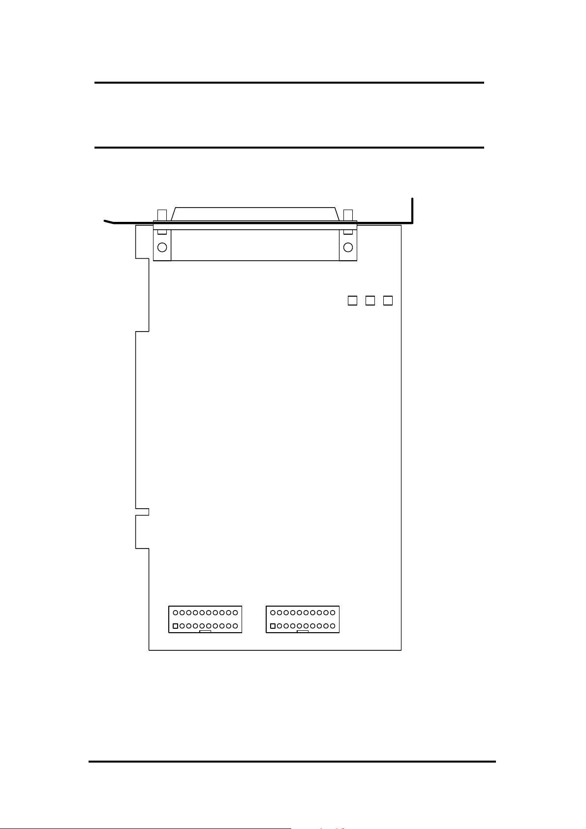
2.1 Board Layout
CON3
OME-PIO-DA8
OME-PIO-DA4
PCI BUS
OME-PIO-DA16
DO
CON1
12
CON1: 16 channels D/O
CON2: 16 channels D/I
CON3: 16/8/4 channels D/A converted voltage/current output
OME-PIO-DA16/8/4 User’s Manual (Ver. 2.1,Nov /2003) ----- 7
1920
12
DI
CON2
1920
Page 10
2.2 Counter Architecture
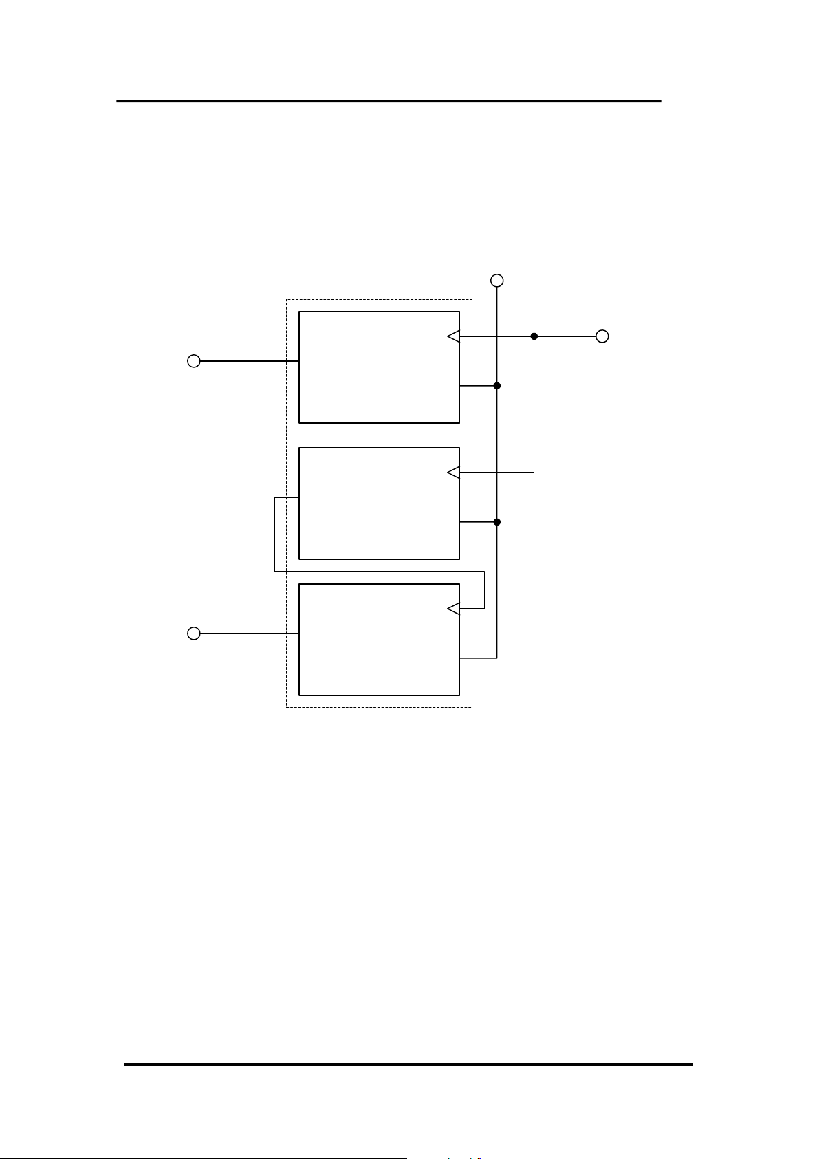
There is one 8254(Timer/Counter) chip on the OME-PIO-DA16/8/4 card. The
block diagram is given as follows:
Vcc
8254 Timer/Counter
INT0
INT1
OUT0
OUT1
OUT2
CLK0
GATE0
Counter0
CLK1
GATE1
Counter1
CLK2
GATE2
Counter2
4MHz
It provides two interrupt source, one is 16 bits timer output (INT0) and the other
one is 32 bits timer output (INT1).
OME-PIO-DA16/8/4 User’s Manual (Ver. 2.1,Nov /2003) ----- 8
Page 11

2.3 Interrupt Operation
There are two interrupt sources in OME-PIO-DA16/8/4. These two signals are
named as INT0 and INT1.Their signal sources are given as follows:
INT0: 8254 counter0 output (Refer to Sec. 2.2)
INT1: 8254 counter2 output (Refer to Sec. 2.2)
If only one interrupt signal source is used, the interrupt service routine doesn’t have
to identify the interrupt source. Refer to DEMO3.C and DEMO4.C for more
information.
If there are more than one interrupt source, the interrupt service routine has to
identify the active signals as follows: (Refer to DEMO5.C and DEMO6.C)
1. Read the new status of all interrupt signal source
2. Compare the new status with old status to identify the active signals
3. If INT0 is active, service it
4. If INT1 is active, service it
5. Save the new status to old status
Note: If the interrupt signal is too short, the new status may be as same as old
status. In that condition the interrupt service routine cannot identify which
interrupt source is active. So the interrupt signal must be hold_active long
enough until the interrupt service routine is executed. This hold_time is different
for different O.S. The hold_time can be as short as micro-second or as long as
second. In general, 20mS is enough for most operating systems.
OME-PIO-DA16/8/4 User’s Manual (Ver. 2.1,Nov /2003) ----- 9
Page 12
2.3.1 Interrupt Block Diagram of
OME-PIO-DA16/8/4
INT\
Level_trigger
INT_CHAN_0
(to PCI slot)
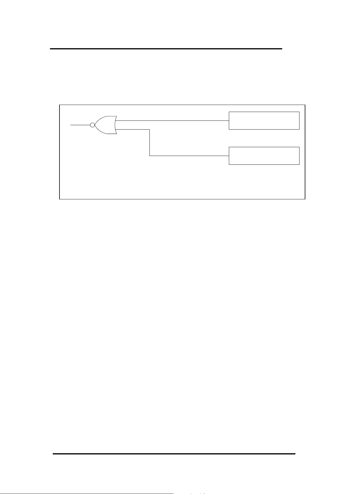
The interrupt output signal of OME-PIO-DA16/8/4, INT\, is Level-Trigger &
Active_Low. If the INT\ generate a low_pulse, the OME-PIO-DA16/8/4 will
interrupt the PC once a time. If INT\ is fixed in low_level, the OME-PIO-DA16/8/4
will interrupt the PC continuously. So the INT_CHAN_0/1 must be controlled in a
pules_type signals. They must be fixed in low_level statue normally and
generated a high_pulse to interrupt the PC.
The priority of INT_CHAN_0/1 is the same. If all these two signals are active at
the same time, then INT\ will be active only once a time. So the interrupt service
routine has to read the status of all interrupt channels for multi channels interrupt.
Refer to Sec. 2.3 for more information.
DEMO5.C → for INT_CHAN_0 & INT_CHAN_1
INT_CHAN_1
initial_low
active_high
If only one interrupt source is used, the interrupt service routine doesn’t have to
read the status of interrupt source. The demo programs DEMO3.C - DEMO4.C are
designed for single-channel interrupt demo as follows:
DEMO3.C → for INT_CHAN_1 only (initial high)
DEMO4.C → for INT_CHAN_1 only (initial low)
OME-PIO-DA16/8/4 User’s Manual (Ver. 2.1,Nov /2003) ----- 10
Page 13
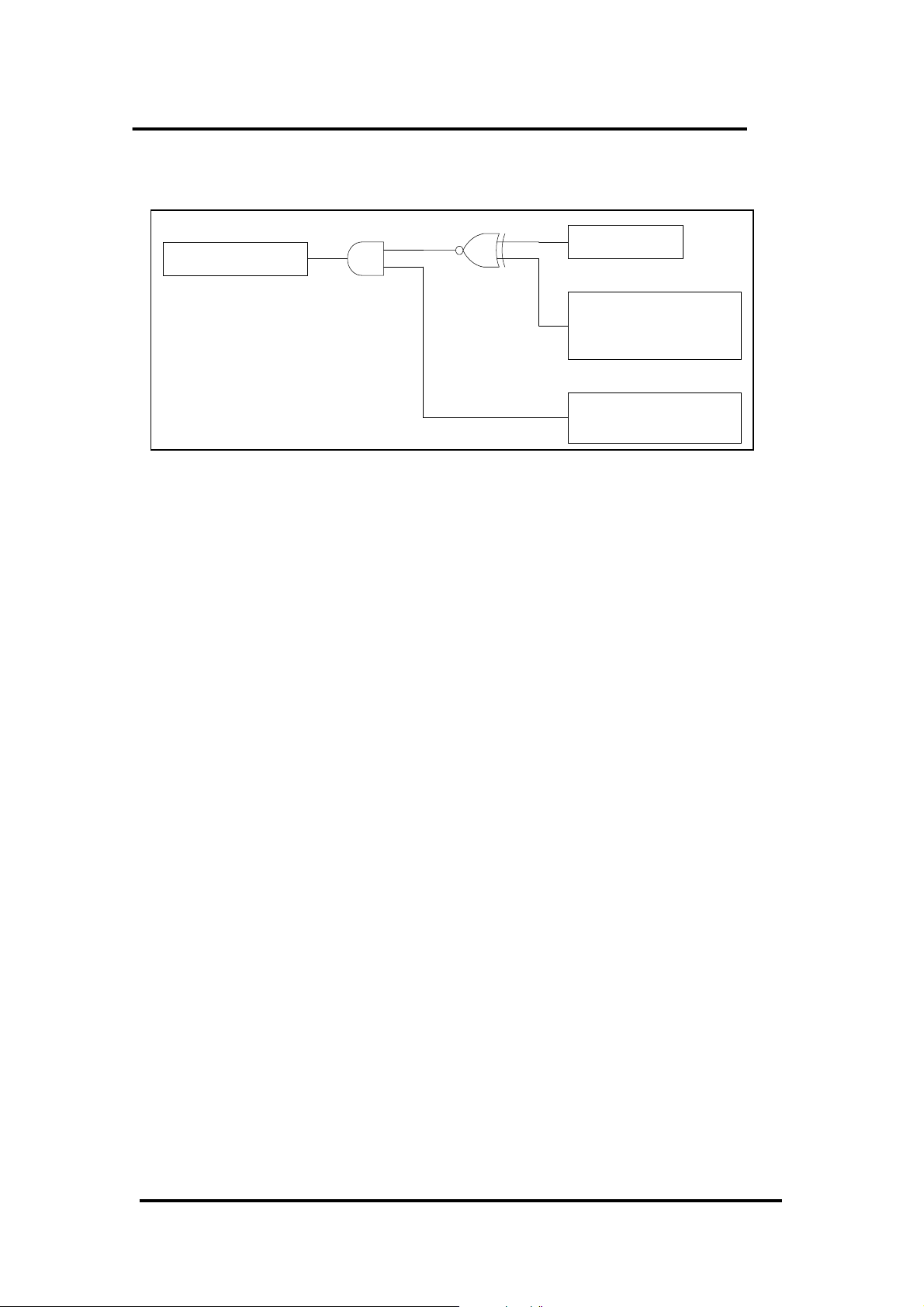
2.3.2 INT_CHAN_0/1
INT_CHAN_0/1
The architecture of INT_CHAN_0 and INT_CHAN_1 is the same as above figure.
The only difference between INT0 and INT1 is that INT_CHAN_0 signal source from
8254 counter0 output and INT_CHAN_1 signal source from 8254 counter2 output.
The INT_CHAN_0/1 must be fixed in low level state normally and generate a
high_pulse to interrupt the PC.
The EN0/1 can be used to enable/disable the INT_CHAN_0/1 as follows: (Refer to
INT0/1
Inverted/Noninverted
select
(INV0/1)
Enable/Disable select
(EN0/1)
Sec.3.3.4)
EN0/1 = 0 → INT_CHAN_0/1 = disable
EN0/1 = 1 → INT_CHAN_0/1 = enable
The INV0/1 can be used to invert/non-invert the INT0/1 as follows: (Refer to
Sec.3.3.6)
INV0/1 = 0 → INT_CHAN_0/1 = inverted state of INT0/1
INV0/1 = 1 → INT_CHAN_0/1 = non-inverted state of INT0/1
If the INT\ fixed in low level state, the OME-PIO-DA16/8/4 will interrupt the
PC continuously. So interrupt service routine should use INV0/1 to invert/non-
invert the INT0/1 to generate high_pulse (Refer to next section)
OME-PIO-DA16/8/4 User’s Manual (Ver. 2.1,Nov /2003) ----- 11
Page 14
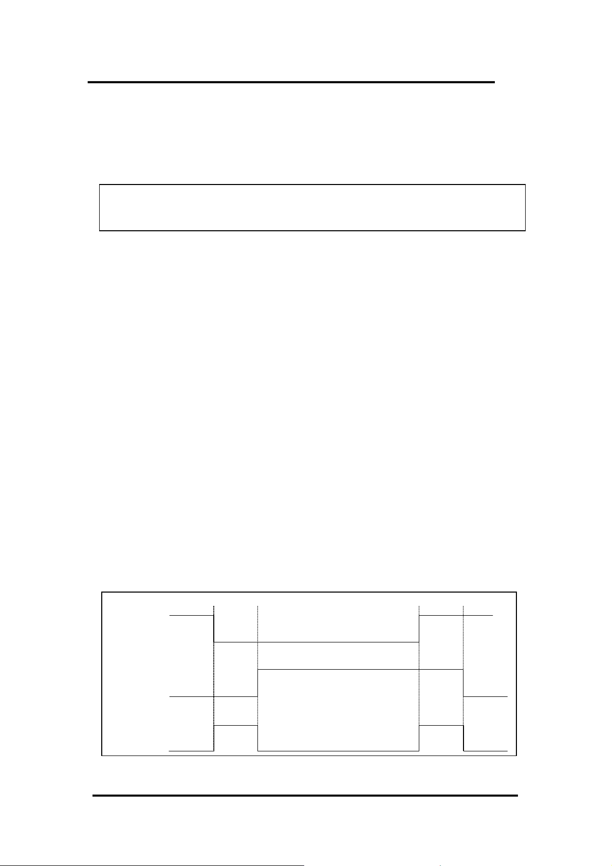
2.3.3 Initial_high, active_low Interrupt source
If the INT0 (8254 counter0 output) is an initial_high, active_low signal
(depend on 8254 counter mode), the interrupt service routine should use INV0 to
invert/ non-invert the INT0 for high_pulse generation as follows: (Refer to DEMO3.C)
Initial set:
now_int_state=1; /* initial state for INT0 */
outportb(wBase+0x2a,0); /* select the inverted INT0 */
void interrupt irq_service()
{
if (now_int_state==1) /* now INT0 is changed to LOW */(a)
{ /* --> INT_CHAN_0=!INT0=HIGH now */
COUNT_L++; /* find a LOW_pulse (INT0) */
If((inport(wBase+7)&1)==0)/* the INT0 is still fixed in LOW */
{ /* Æ need to generate a high_pulse */
outportb(wBase+0x2a,1);/* INV0 select the non-inverted input */(b)
/* INT_CHAN_0=INT0=LOW --> */
/* INT_CHAN_0 generate a high_pulse */
now_int_state=0; /* now INT0=LOW */
}
else now_int_state=1; /* now INT0=HIGH */
/* don’t have to generate high_pulse */
}
else /* now INT0 is changed to HIGH */(c)
{ /* --> INT_CHAN_0=INT0=HIGH now */
COUNT_H++; /* find a HIGH_pulse (INT0) */
If((inport(wBase+7)&1)==1)/* the INT0 is still fixed in HIGH */
{ /* need to generate a high_pulse */
outportb(wBase+0x2a,0);/* INV0 select the inverted input */(d)
/* INT_CHAN_0=!INT0=LOW --> */
/* INT_CHAN_0 generate a high_pulse */
now_int_state=1; /* now INT0=HIGH */
}
else now_int_state=0; /* now INT0=LOW */
/* don’t have to generate high_pulse */
}
if (wIrq>=8) outportb(A2_8259,0x20);
outportb(A1_8259,0x20);
}
INT0
(a) (b) (c) (d)
INV0
INT_CHAN_0
OME-PIO-DA16/8/4 User’s Manual (Ver. 2.1,Nov /2003) ----- 12
Page 15
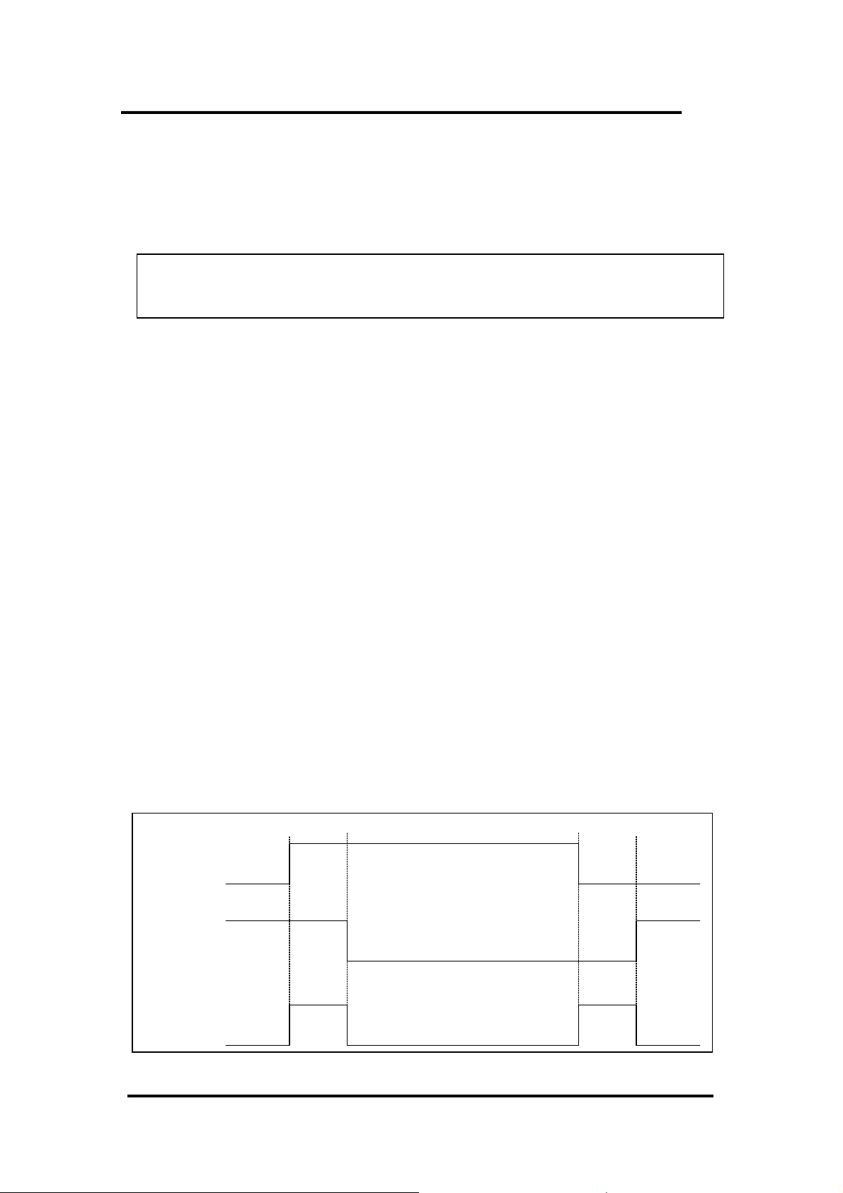
2.3.4 Initial_low, active_high Interrupt source
If the INT0 (8254 counter0 output) is an initial_low, active_high signal
(depend on 8254 counter mode), the interrupt service routine should use INV0 to
invert/non-invert the INT0 for high_pulse generation as follows: (Refer to DEMO4.C)
Initial set:
now_int_state=0; /* initial state for INT0 */
outportb(wBase+0x2a,1); /* select the non-inverted INT0 */
void interrupt irq_service()
{
if (now_int_state==1) /* now INT0 is changed to LOW */(c)
{ /* --> INT_CHAN_0=!INT0=HIGH now */
COUNT_L++; /* find a LOW_pulse (INT0) */
If((inport(wBase+7)&1)==0)/* the INT0 is still fixed in LOW */
{ /* Æ need to generate a high_pulse */
outportb(wBase+0x2a,1);/* INV0 select the non-inverted input */(d)
/* INT_CHAN_0=INT0=LOW --> */
/* INT_CHAN_0 generate a high_pulse */
now_int_state=0; /* now INT0=LOW */
}
else now_int_state=1; /* now INT0=HIGH */
/* don’t have to generate high_pulse */
}
else /* now INT0 is changed to HIGH */(a)
{ /* --> INT_CHAN_0=INT0=HIGH now */
COUNT_H++; /* find a High_pulse (INT0) */
If((inport(wBase+7)&1)==1)/* the INT0 is still fixed in HIGH */
{ /* need to generate a high_pulse */
outportb(wBase+0x2a,0);/* INV0 select the inverted input */(b)
/* INT_CHAN_0=!INT0=LOW --> */
/* INT_CHAN_0 generate a high_pulse */
now_int_state=1; /* now INT0=HIGH */
}
else now_int_state=0; /* now INT0=LOW */
/* don’t have to generate high_pulse */
}
if (wIrq>=8) outportb(A2_8259,0x20);
outportb(A1_8259,0x20);
}
INT0
(a) (b) (c) (d)
INV0
INT_CHAN_0
OME-PIO-DA16/8/4 User’s Manual (Ver. 2.1,Nov /2003) ----- 13
Page 16
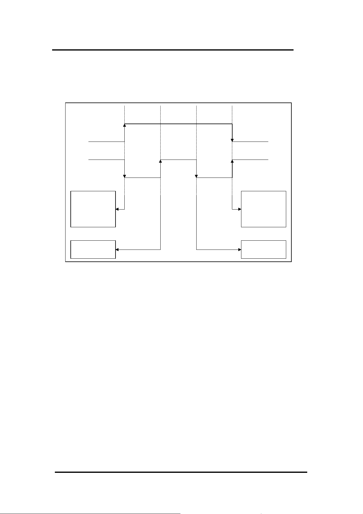
2.3.5 Multiple Interrupt Source
Assume: INT0 is initial Low, active High,
INT1 is initial High, active Low
as follows:
INT0
INT1
INT0 & INT1
are active at
the same time
INT0 & INT1
are return to
normal at the
same time
INT1 is return
to normal
INT1 is active
Refer to DEMO5.C for source program. All of these falling-edge & rising-edge can
be detected by DEMO5.C.
Note: when the interrupt is active, the user program has to identify the active
signals. These signals may be active at the same time. So the interrupt service
routine has to service all active signals at the same time.
OME-PIO-DA16/8/4 User’s Manual (Ver. 2.1,Nov /2003) ----- 14
Page 17

/* -------------------------------------------------------------- */
/* Note : 1.The hold_time of INT_CHAN_0 & INT_CHAN_1 must long */
/* enoug. */
/* 2.The ISR must read the interrupt status again to */
/* identify the active interrupt source. */
/* 3.The INT_CHAN_0 & INT_CHAN_1 can be active at the same */
/* time. */
/* -------------------------------------------------------------- */
void interrupt irq_service()
{
/* now ISR can not know which interrupt is active */
new_int_state=inportb(wBase+7)&0x03; /* read all interrupt */
/* signal state */
int_c=new_int_state^now_int_state; /* compare new_state to */
/* old_state */
if ((int_c&0x01)==1) /* INT_CHAN_0 is active */
{
if ((new_int_state&1)==0) /* INT0 change to low now */
{
INT0_L++;
}
else /* INT0 change to high now */
{
INT0_H++;
}
invert=invert^1; /* generate high_pulse */
}
if ((int_c&0x02)==2) /* INT_CHAN_1 is active */
{
if ((new_int_state&2)==0) /* INT1 change to low now */
{
INT1_L++;
}
else /* INT1 change to high now */
{
INT1_H++;
}
invert=invert^2; /* generate high_pulse */
}
now_int_state=new_int_state; /* update interrupt status */
outportb(wBase+0x2a,invert); /* generate a high pulse */
if (wIrq>=8) outportb(A2_8259,0x20);
outportb(A1_8259,0x20);
}
OME-PIO-DA16/8/4 User’s Manual (Ver. 2.1,Nov /2003) ----- 15
Page 18
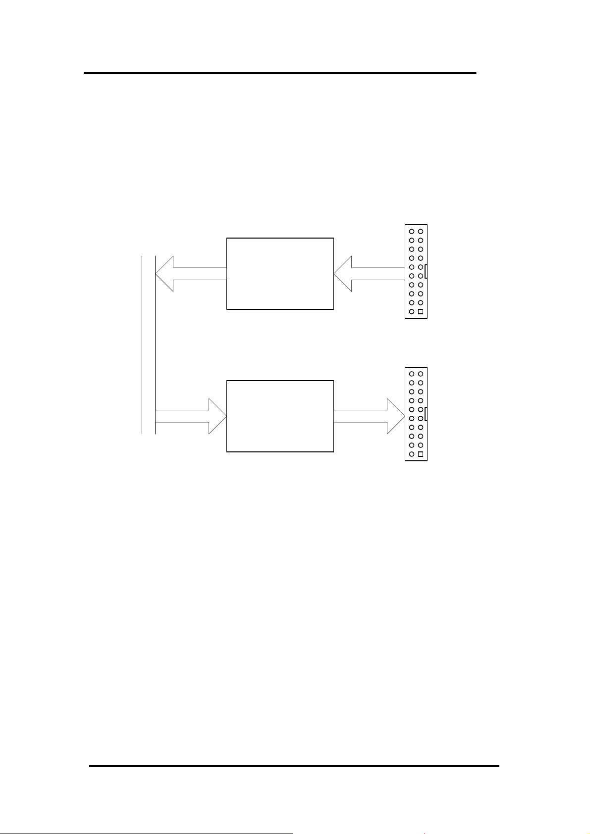
2.4 D/I/O Block Diagram
The OME-PIO-DA16/8/4 provides 16 channels of digital input and 16 channels of
digital output. All signal levels are TTL compatible. The connection diagram and
block diagram are given as follows:
CON2
D/I port
Local Data Bus
D/O port
16 bits16 bits
CON1
16 bits16 bits
The D/I port can be connected to the OME-DB-16P. The OME-DB-16P is a 16-
channel isolated digital input daughter board. The D/O port can be connected to the
OME-DB-16R or OME-DB-24PR. The OME-DB-16R is a 16-channel relay output
board. The OME-DB-24PR is a 24-channel power relay output board.
OME-PIO-DA16/8/4 User’s Manual (Ver. 2.1,Nov /2003) ----- 16
Page 19
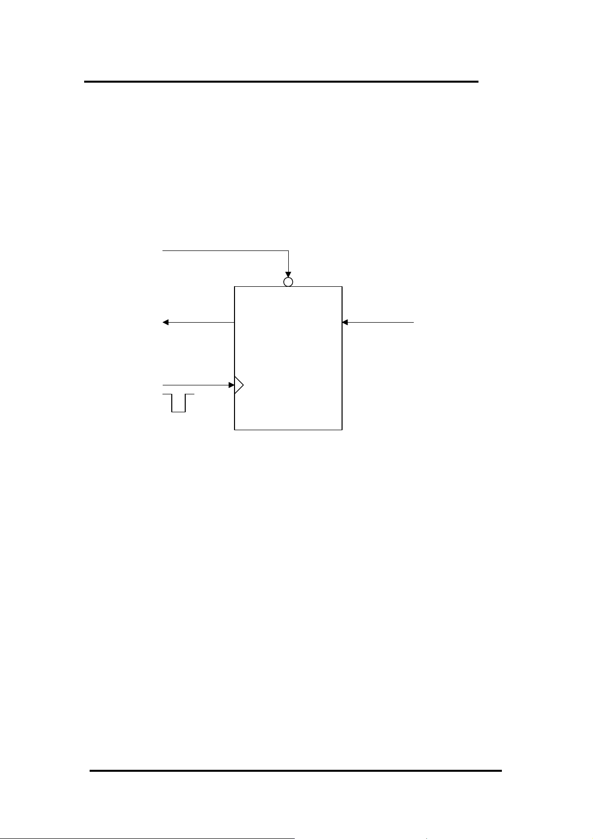
2.4.1 DI Port Architecture (CON2)
When the PC is powered-up, all operation of DI port (CON2) is disable. The
enable/disable of DI port is controlled by the RESET\ signal. Refer to Sec. 3.3.1 for
more information about RESET\ signal.
• The RESET\ is in Low-state Æ all DI operation is disable
• The RESET\ is in High-state Æ all DI operation is enable
RESET\
disable
Data
Buffer input
Clock input
CON2
D/I buffer CKT
OME-PIO-DA16/8/4 User’s Manual (Ver. 2.1,Nov /2003) ----- 17
Page 20
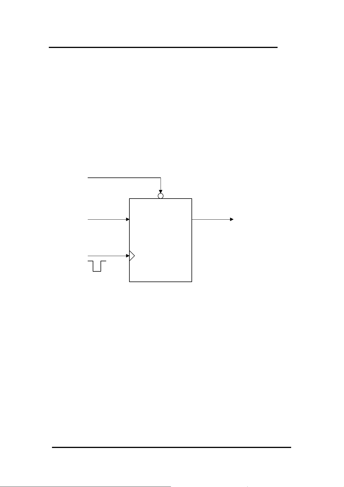
2.4.2 DO Port Architecture (CON1)
When the PC is powered-up, all of DO states are clear to low state. The
RESET\ signal is used to clear DO states. Refer to Sec. 3.3.1 for more information
about RESET\ signal.
• The RESET\ is in Low-state Æ all DOs are clear to low state
The block diagram of DO is given as follows:
RESET\
clear
Data
input Latch
CON1
Clock input
D/O buffer CKT
OME-PIO-DA16/8/4 User’s Manual (Ver. 2.1,Nov /2003) ----- 18
Page 21
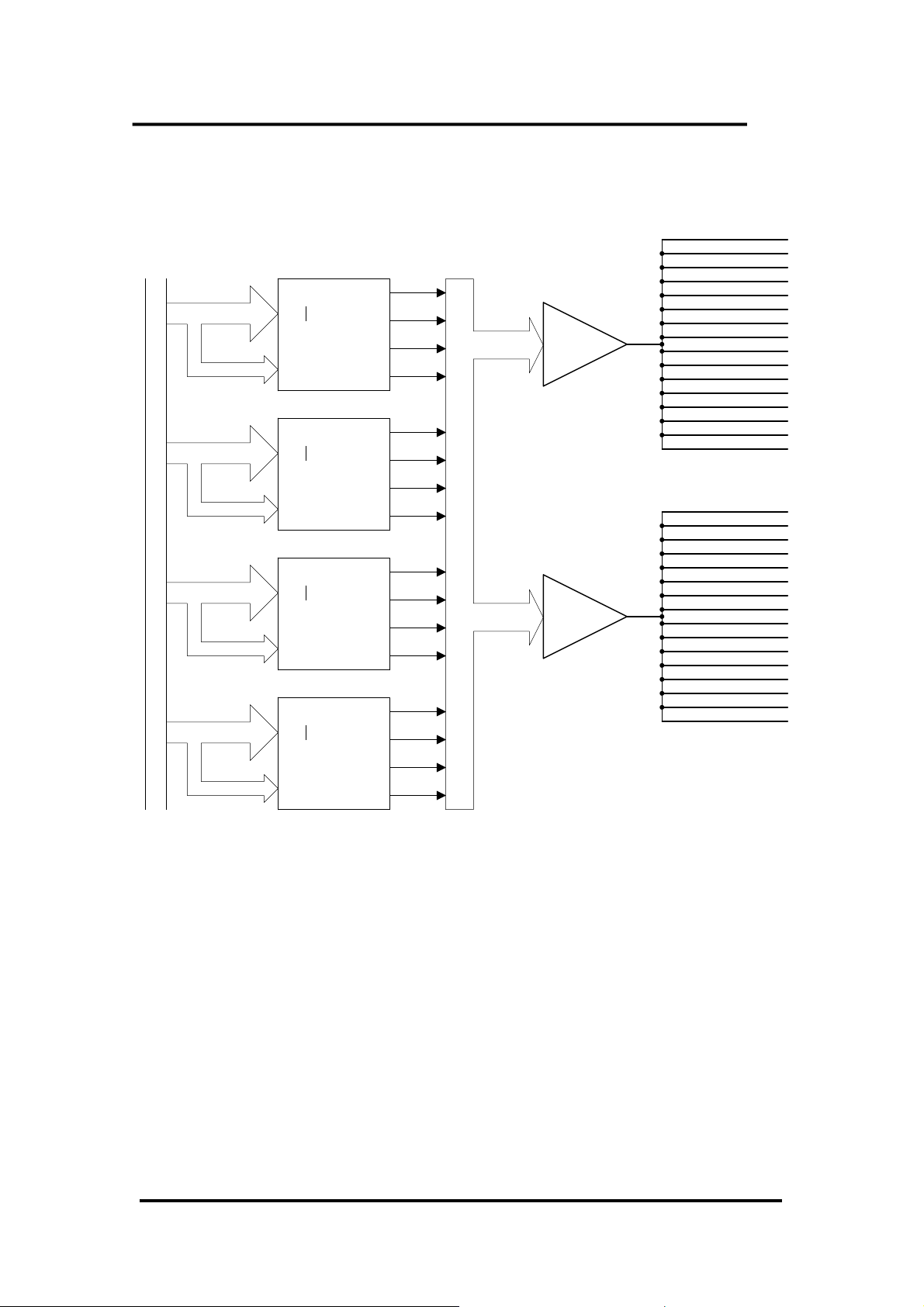
2.5 D/A Architecture
DA_0
DA 0D0
d0~d13
D13
d14~d15
A0
A1
DA_1
Buffered Data Bus (16 bits)
d0~d13
D13
d14~d15
A0
A1
DA_2
d0~d13
D13
d14~d15
A0
A1
DA_3
d0~d13
D13
d14~d15
A0
A1
DA 1
DA 2
DA 3
DA 4D0
DA 5
DA 6
DA 7
DA 8D0
DA 9
DA10
DA11
DA12D0
DA13
DA14
DA15
Amp
Amp
Voltage Output 0
Voltage Output 1
Voltage Output 2
Voltage Output 3
Voltage Output 4
Voltage Output 5
Voltage Output 6
Voltage Output 7
Voltage Output 8
Voltage Output 9
Voltage Output 10
Voltage Output 11
Voltage Output 12
Voltage Output 13
Voltage Output 14
Voltage Output 15
Current Output 0
Current Output 1
Current Output 2
Current Output 3
Current Output 4
Current Output 5
Current Output 6
Current Output 7
Current Output 8
Current Output 9
Current Output 10
Current Output 11
Current Output 12
Current Output 13
Current Output 14
Current Output 15
The OME-PIO-DA16/8/4 offers 16/8/4 channels double-buffered digital to analog
output and provide voltage output & current output simultaneously.
OME-PIO-DA16/8/4 User’s Manual (Ver. 2.1,Nov /2003) ----- 19
Page 22
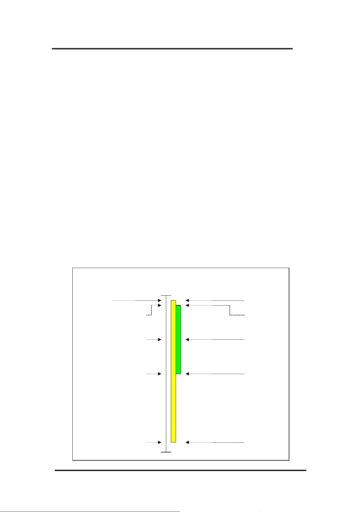
2.6 D/A Convert Operation
The D/A converters on OME-PIO-DA16/8/4 have 14 bits of resolution, so the
digital data value range from 0x0000 to 0x3fff. And the hardware is designed to
output voltage range from -10.1~+10.1 as follows:
0x0000 → about –10.1 volt
0x3FFF → about +10.1 volt
In the conventional design, there will be some VRs to adjust to let 0x0000=-10.0V
& 0x3fff=+10.0V for voltage output. Also these VRs have to be adjusted to let
0x1fff=0mA & 0x3fff=20mA for current output. In the conventional design, these
VRs are common for voltage/current output. So the user has to perform calibration
when change from voltage to current. Also If these VRs are changed, the user has to
perform calibration again. This procedure is complex & heavy load. The OME-PIO-
DA16/8/4 use software calibration to replace this complex procedure as following:
• for each voltage output channel we find two hex value MaxV[n] and MinV[n]
(stored to on board EEPROM). MaxV[n] mapping to accurate +10V and MinV[n]
mapping to accurate –10V.
• For each current output channel we also find two hex value MaxI[n] and MinI[n]
(stored to on board EEPROM). MaxI[n] mapping to accurate 20mA and MinI[n]
mapping to accurate 0mA.
MaxV[n]
Hex Value
0X3FFF +10.1V / +10.?V
MaxI[n]
Ideal / Actual
Calibration
+10.0V
20mA
DaValue Vout / Iout
MinI[n]
0mA
OME-PIO-DA16/8/4 User’s Manual (Ver. 2.1,Nov /2003) ----- 20
MinV[n]
0X0000
-10.1V / -10.?V
-10.0V
Page 23

Therefore the software can calibrate the analog output without any hardware Trim-
pot adjustment. For example,
channel n MinV[n] MaxV[n] MinI[n] MaxI[n]
0 134 16297 8180 15943
1 137 16293 8172 15976
2 132 16296 8199 15949
3 134 16391 8177 15963
4 135 16298 8165 15955
5 131 16292 8150 15947
6 136 16295 8172 15968
7 134 16297 8163 15961
8 134 16294 8188 15959
9 132 16295 8169 15948
10 135 16298 8172 15946
11 133 16296 8177 15975
12 131 16292 8159 15942
13 134 16297 8173 15973
14 132 16293 8168 15949
15 133 16295 8175 15965
If the user want to send Vout(volt) to channel n, the calibrated hex value, DaValue,
sent to D/A converter is give as follows:
DeltaV[n]=20.0/(MaxV[n]–MinV[n]); /* DeltaV[n]=volt per count at channel_n */
DaValue=(Vout+10.0)/DeltaV[n]+MinV[n]; /* DaValue=Hex value send to D/A */
pio_da16_da(n,DaValue); /* send DaValue to channel n */
If the user want to send Iout(mA) to channel n, the calibrated hex value, DaValue,
sent to D/A converter is give as follows: (Refer to DEMO9.C)
DeltaI[n]=20.0/(MaxI[n]–MinI[n]); /* DeltaI[n]=mA per count at channel_n */
DaValue=Iout/DeltaI[n]+MinI[n]; /* DaValue=Hex value send to D/A */
pio_da16_da(n,DaValue); /* send DaValue to channel n */
Refer to DEMO7.C and DEMO9.C for more information.
OME-PIO-DA16/8/4 User’s Manual (Ver. 2.1,Nov /2003) ----- 21
Page 24
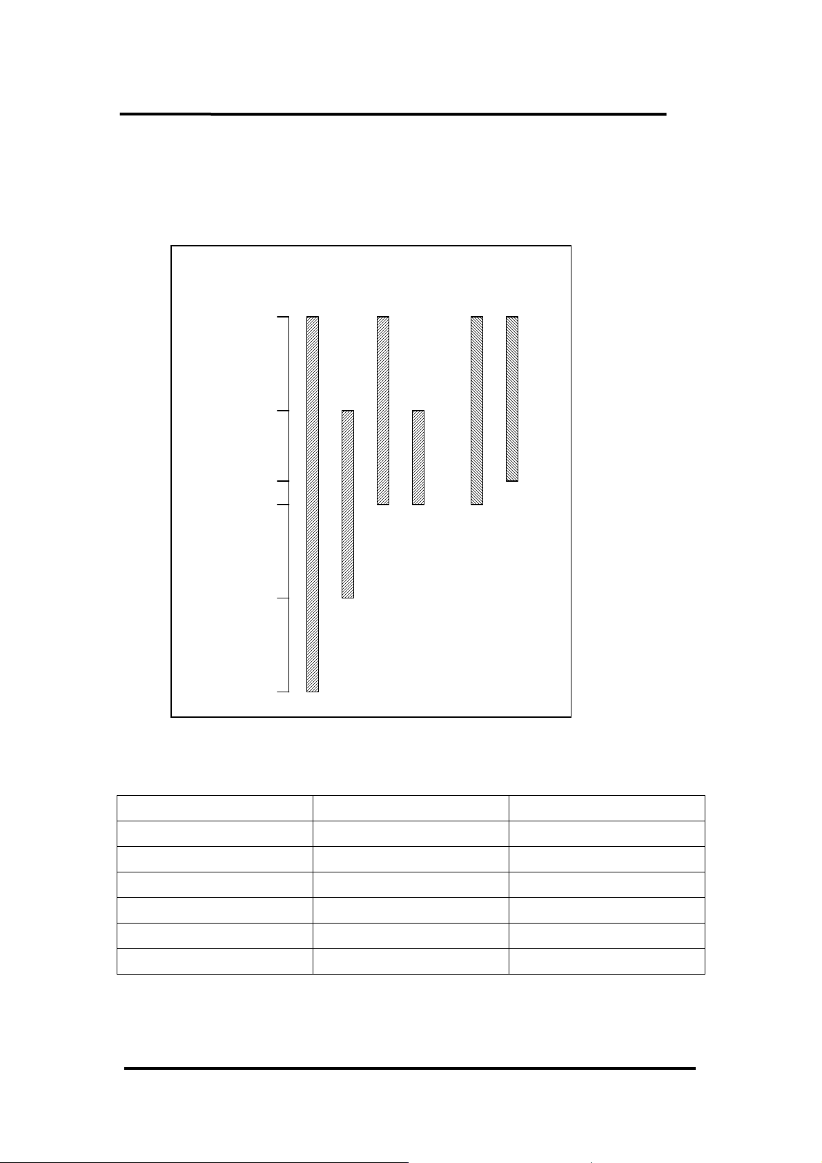
2.6.1 Output Range and Resolution
V
The voltage output range of OME-PIO-DA16/8/4 is always in ±10.1V and the
current output range is always in 0~22mA as following:
Hex Value
0X3FFF
+10.1V
oltage
Channel Output
+10.1V
Current
Channel Output
22mA
22mA
0X2FFF
+5.05V
+5.05V
0X25D0
0X1FFF
0V
0V
0X0FFF
-5.05V
0X0000
-10.1V
The resolution of each range is given as follows:
4mA
0mA
Configuration Equivalent Bit Resolution
-10V ~ +10V 14 bit 1.22mV
0V ~ 10V 13 bit 1.22mV
-5V ~ +5V 13 bit 1.22mV
0V ~ +5V 12 bit 1.22mV
0mA ~ 20mA 13 bit 2.70uA
4mA ~ 20mA 13 bit 2.70uA
OME-PIO-DA16/8/4 User’s Manual (Ver. 2.1,Nov /2003) ----- 22
Page 25

2.6.2 The ±10V Voltage Output
The voltage output of OME-PIO-DA16/8/4 is always in ±10.1V range. If the user
needs to output ±10V range, the software is same as described in Sec.2.6. Because the
user wants to output ±10V range, Vout will be in ±10V range, the DaValue will be
about from 0x0000 to 0x3fff. This means the resolution is about 14 bit.
2.6.3 The ±5V Voltage Output
The voltage output of OME-PIO-DA16/8/4 is always in ±10.1V range. If the user
needs to output ±5V range, the software is same as described in Sec.2.6. Because the
user wants to output ±5V range, Vout will be in ±5V range, the DaValue will be
about from 0x0fff to 0x2fff. This means the resolution is about 13 bits.
2.6.4 The 0~10V Voltage Output
The voltage output of OME-PIO-DA16/8/4 is always in ±10V.1 range. If the user
needs to output 0~10V range, the software is same as described in Sec.2.6. Because
the user wants to output 0~10V range, Vout will be in 0~10V range, the DaValue will
be about from 0x1fff to 0x3fff. This means the resolution is about 13 bits.
2.6.5 The 0~5V Voltage Output
The voltage output of OME-PIO-DA16/8/4 is always in ±10.1V range. If the user
needs to output 0~5V range, the software is same as described in Sec.2.6. Because the
user wants to output 0~5V range, Vout will be in 0~5V range, the wDaValue will be
about from 0x1fff to 0x2fff. This means the resolution is about 12 bits.
OME-PIO-DA16/8/4 User’s Manual (Ver. 2.1,Nov /2003) ----- 23
Page 26

2.6.6 The 0~20mA Current Output
The current output of OME-PIO-DA16/8/4 is always in 0~22mA range. If the user
needs to output 0~20mA, the software is the same as described in Sec.2.6. Because
the user wants to output 0~20mA, Iout will be in the 0~20mA range. So the DaValue
will be about from 0x1fff to 0x3fff. This means the resolution is about 13 bits.
2.6.7 The 4~20mA Current Output
The current output of OME-PIO-DA16/8/4 is always in 0~22mA range. If the user
needs to output 4~20mA, the software is the same as described in Sec.2.6. Because
the user wants to output 4~20mA, Iout will be in the 4~20mA range. So the DaValue
will be about from 0x2600 to 0x3fff. This means the resolution is about 13 bits.
OME-PIO-DA16/8/4 User’s Manual (Ver. 2.1,Nov /2003) ----- 24
Page 27

2.6.8 No VR & No Jumper Design
In the conventional 12-bit D/A board, for example OME-A-626/A-628, there are
jumpers for the following functions:
(1) select the reference voltage (internal –10/-5/or external)
(2) select unipolar/bipolar (0-10V or ±10V)
(3) select different output range (0-10V or 0-5V)
And there are many VRs for the following functions:
(1) voltage output offset adjustment
(2) voltage output full-scale adjustment
(3) current output offset adjustment
(4) current output full-scale adjustment
There are so many VRs and jumpers, this make the QC and re-calibration very
difficult. Every step must be performed manually making is difficult to calibrate these
D/A boards.
The design of the OME-PIO-DA/16/8/4 removed all these VRs and jumpers but
still maintain the same precision and performance. There is a 14-bit D/A converter
and software calibration to provide at least the same performance & precision as
OME-A-626/A-628 as follows:
Configuration Equivalent Bit Resolution
-10V ~ +10V 14 bit 1.22mV
0V ~ 10V 13 bit 1.22mV
-5V ~ +5V 13 bit 1.22mV
0V ~ +5V 12 bit 1.22mV
0mA ~ 20mA 13 bit 2.70uA
4mA ~ 20mA 13 bit 2.70uA
• All these VRs and jumpers are removed.
• All calibrations can be done by software.
• All channel configurations can be selected by software, no need to change any
hardware.
• The Precision is at least the same as OME-A-626/A628.
• All these 16 channels can be configured and used in the different configuration at
the same time. (For example, channel_0=±10V, channel_1=4~20mA,
channel_2=0~5V, …).
• All these features can be implemented in a small, compact, reliable and half-size
PCB.
OME-PIO-DA16/8/4 User’s Manual (Ver. 2.1,Nov /2003) ----- 25
Page 28

2.6.9 Factory Software Calibration
It is recommended to use a 16-bit A/D card to calibration the OME-PIO-
DA16/8/4. The OME-I-7000 series is a set of precision remote control modules. The
I-7017 is 8-channel 16-bit precision A/D module (24-bit sigma-delta A/D converter),
we use two OME-I-7017 for voltage output calibration and another two OME-I-7017
for current output calibration.
The steps for channel_n voltage calibration are given as follows:
Step 1: DaValue=0
Step 2: send DaValue to OME-PIO-DA16/8/4 channel_n
Step 3: measure the I-7017 channel_n,
If this value is just >= -10V, than goto step 5
Step 4: incrememt DaValue, goto step 2
Step 5: MinV[n]=DaValue-1
Step 6: DaValue=0x3fff
Step 7: send DaValue to OME-PIO-DA16/8/4 channel_n
Step 8: measure the I-7017 channel_n,
If this value is just >= +10V, than goto step 10
Step 9: increment DaValue, goto step 7
Step 10: MaxV[n]=DaValue
Note: MinV[n] & MaxV[n] are discribed in Sec.2.6
The steps for channel_n current calibration are given as follows:
Step 1: DaValue=0x1fff
Step 2: send DaValue to OME-PIO-DA16/8/4 channel_n
Step 3: measure the I-7017 channel_n,
If this value is just >= 0mA, than goto step 5
Step 4: incrememt DaValue, goto step 2
Step 5: MinI[n]=DaValue-1
Step 6: DaValue=0x3fff
Step 7: send DaValue to OME-PIO-DA16/8/4 channel_n
Step 8: measure the I-7017 channel_n,
If this value is just >= 20mA, than goto step 10
Step 9: increment DaValue, goto step 7
Step 10: MaxI[n]=DaValue
Note: MinI[n] & MaxI[n] are discribed in Sec.2.6
OME-PIO-DA16/8/4 User’s Manual (Ver. 2.1,Nov /2003) ----- 26
Page 29

2.6.10 User Software Calibration
User can perform calibration with a voltage meter and a current meter.
Step1: Run DEMO12.EXE
Step2: Select card number (OME-PIO-DA16/OME-PIO-DA8/OME-PIO-DA4) that
you want to calibrate
Step3: Select which item (MinV[n]/MaxV[n]/MinI[n]/MaxI[n]) that you want to
calibrate
Step4: To measure the analog output by voltage meter or current meter and decide to
increment or decrement DaValue. The DaValue will send to D/A converter at
once. By the measured result user can find the proper value of DaValue that
mapping to accurate output value.
Step5: Repeat step 4 for each channel
After this procedure, the new data of MinV[n]/MaxV[n]/MinI[n]/MaxI[n] will be
stored to on board EEPROM.
User can run DEMO10.EXE to back-up the old calibration data to
“A:\DA16.DAT” before new calibration.
If something error during the new calibration, user can run DEMO11.EXE to
download data from “A:\DA16.DAT” to EEPROM.
Note :
DEMO10.EXE → save old calibration data
DEMO11.EXE → download old calibration data
DEMO12.EXE → perform new calibration
OME-PIO-DA16/8/4 User’s Manual (Ver. 2.1,Nov /2003) ----- 27
Page 30
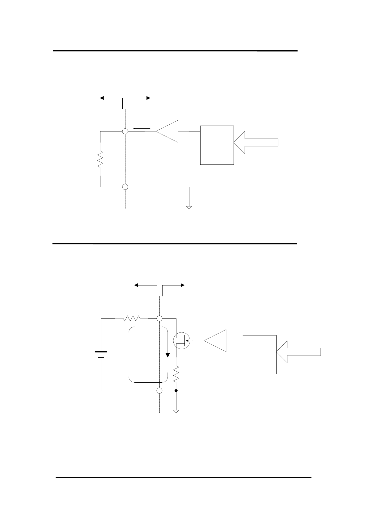
2.6.10 Voltage Output Connection
InternalExternal
Load
Output Current
Max (+/- 5mA)
Amp
D/A Converter
V
out
AGND
D0
D13
2.6.11 Current Output Connection
InternalExternal
Current Loop
0~20mA
Load
+-
14-bits Data
D/A Converter
out
D0
14-bits Data
D13
External Power
Supply 9~36V
AGND
Amp
V
OME-PIO-DA16/8/4 User’s Manual (Ver. 2.1,Nov /2003) ----- 28
Page 31
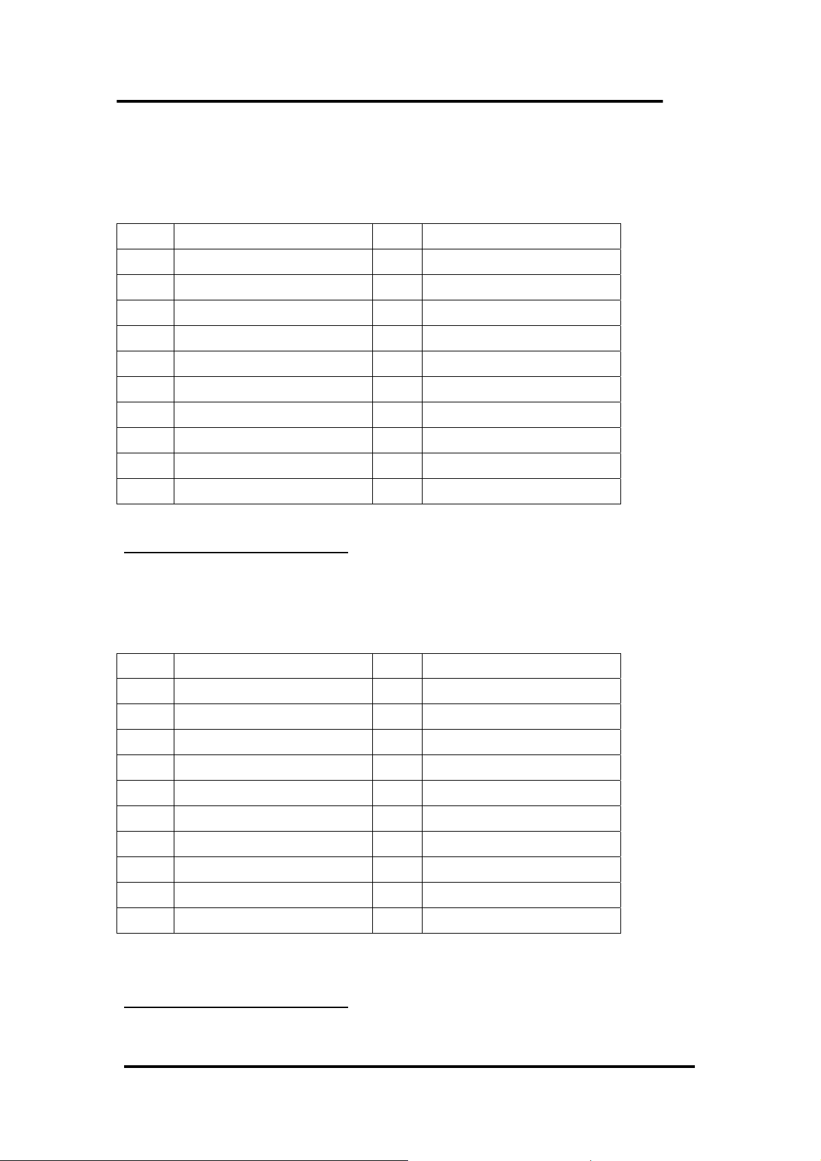
2.7 The Connectors
CON1: Digital Output Connector
Pin Assignment:
Pin Name Pin Name
1 Digital Output 0 2 Digital Output 1
3 Digital Output 2 4 Digital Output 3
5 Digital Output 4 6 Digital Output 5
7 Digital Output 6 8 Digital Output 7
9 Digital Output 8 10 Digital Output 9
11 Digital Output 10 12 Digital Output 11
13 Digital Output 12 14 Digital Output 13
15 Digital Output 14 16 Digital Output 15
17 PCB ground 18 PCB ground
19 PCB +5V 20 PCB +12V
All signals are TTL compatible.
CON2: Digital input connector
Pin assignment:
Pin Name Pin Name
1 Digital Input 0 2 Digital Input 1
3 Digital Input 2 4 Digital Input 3
5 Digital Input 4 6 Digital Input 5
7 Digital Input 6 8 Digital Input 7
9 Digital Input 8 10 Digital Input 9
11 Digital Input 10 12 Digital Input 11
13 Digital Input 12 14 Digital Input 13
15 Digital Input 14 16 Digital Input 15
17 PCB ground 18 PCB ground
19 PCB +5V 20 PCB +12V
All signals are TTL compatible.
OME-PIO-DA16/8/4 User’s Manual (Ver. 2.1,Nov /2003) ----- 29
Page 32

CON3: Analog Output Connector
Pin Assignment:
Pin Name Pin Name
1 Voltage Output 0 20 Current Output 0
2 Voltage Output 1 21 Current Output 1
3 Voltage Output 2 22 Current Output 2
4 Voltage Output 3 23 Current Output 3
5 Analog ground 24 Analog ground
6 Voltage Output 4 25 Current Output 4
7 Voltage Output 5 26 Current Output 5
8 Voltage Output 6 27 Current Output 6
9 Voltage Output 7 28 Current Output 7
10 Analog ground 29 Analog ground
11 Voltage Output 8 30 Current Output 8
12 Voltage Output 9 31 Current Output 9
13 Voltage Output 10 32 Current Output 10
14 Voltage Output 11 33 Current Output 11
15 Analog ground 34 Current Output 12
16 Voltage Output 12 35 Current Output 13
17 Voltage Output 13 36 Current Output 14
18 Voltage Output 14 37 Current Output 15
19 Voltage Output 15
OME-PIO-DA16/8/4 User’s Manual (Ver. 2.1,Nov /2003) ----- 30
Page 33
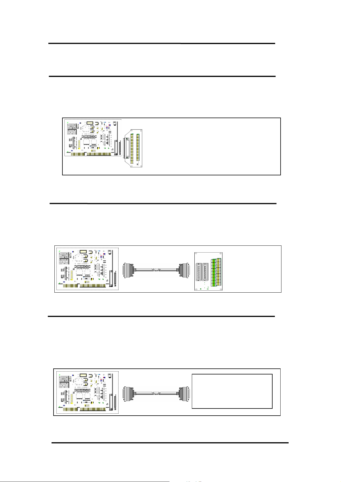
2.8 Daughter Boards
2.8.1 OME-DB-37
The OME-DB-37 is a general purpose daughter board for D-sub 37 pins. It is
designed for easy wire connection.
2.8.2 OME-DN-37
The OME-DN-37 is a general purpose daughter board for OME-DB-37 with DIN-
Rail Mounting. This board is designed for easy wire connection.
37pin cable
OME-DN-37
2.8.3 OME-DB-8125
The OME-DB-8125 is a general purpose screw terminal board. It is designed for
easy wire connection. There are one OME-DB-37 & two 20-pin flat-cable headers in the
OME-DB-8125.
37pin cable
OME-DB-8125
(OME-DB-37 or
20-pin flat-cable header)
OME-PIO-DA16/8/4 User’s Manual (Ver. 2.1,Nov /2003) ----- 31
Page 34
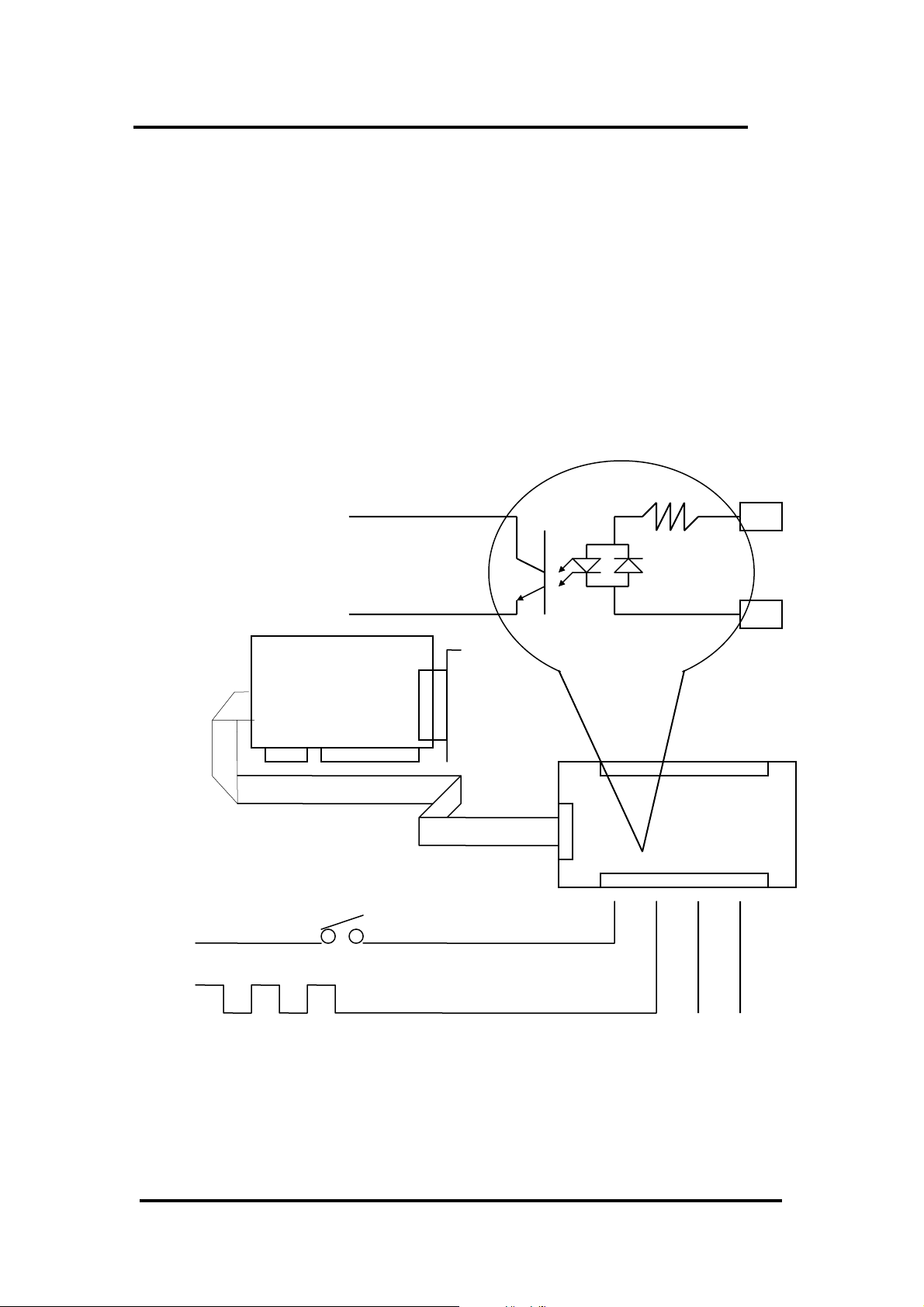
2.8.4 OME-DB-16P Isolated Input Board
The OME-DB-16P is a 16-channels isolated digital input daughter board. The
optically isolated inputs of the OME-DB-16P consist of a bi-directional opto-coupler
with a resistor for current sensing. You can use the OME-DB-16P to sense DC signal
from TTL levels up to 24V or use the OME-DB-16P to sense a wide range of AC
signals. You can use this board to isolate the computer from large common-mode
voltage, ground loops and transient voltage spike that often occur in industrial
environments.
OME-PIO-DA16/8/4
Opto-Isolated
OME-PIO-DA16/8/4
20Pin cable
OME-DB-16P
AC or DC Signal
0V to 24V
+
-
OME-PIO-DA16/8/4 User’s Manual (Ver. 2.1,Nov /2003) ----- 32
Page 35
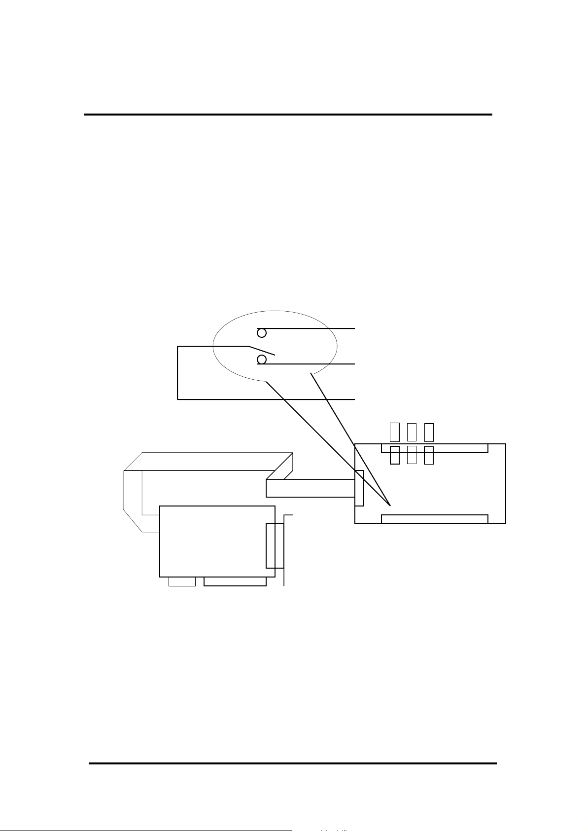
2.8.5 OME-DB-16R Relay Board
The OME-DB-16R, 16-channel relay output board, consists of 16 form C relays
for efficient switch of load by programmed control. It is connector and functionally
compatible with 785 series board but with industrial type terminal block. The relay
are energized by apply 5 volt signal to the appropriated relay channel on the 20-pin
flat connector. There are 16 enunciator LEDs for each relay, light when their
associated relay is activated. To avoid overloading your PC’s power supply, this
board provides a screw terminal for external power supply.
Form C Relay
20Pin cable
OME-PIO-DA16/8/4
Normal Open
Normal Close
Com
OME-DB-16R
Note:
Channel: 16 Form C Relays
Relay: Switching up to 0.5A at 110ACV
or 1A at 24DCV
OME-PIO-DA16/8/4 User’s Manual (Ver. 2.1,Nov /2003) ----- 33
Page 36
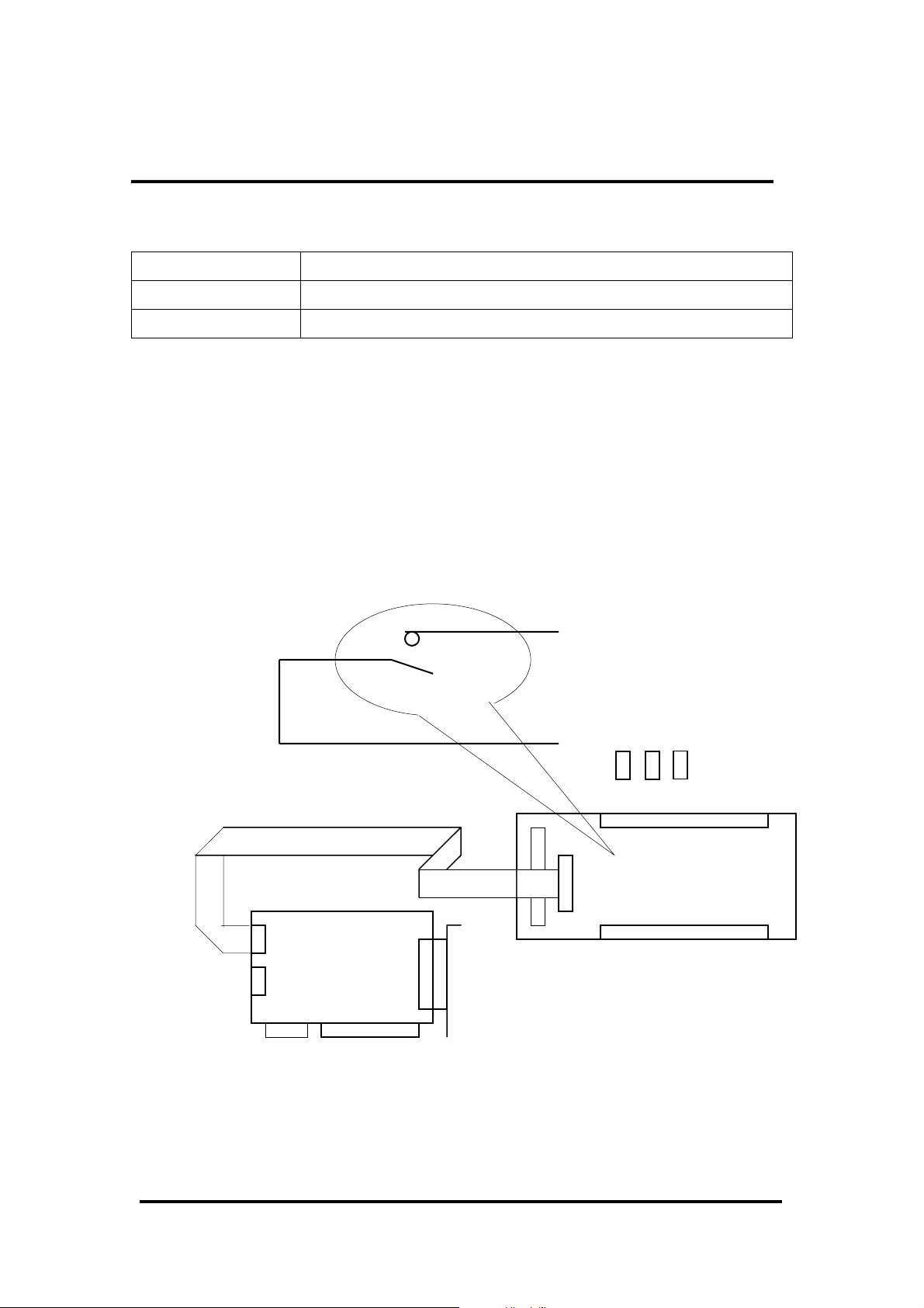
2.8.6. OME-DB-24PR/DB-24POR/DB-24C
OME-DB-24PR 24*power relay, 5A/250V
OME-DB-24POR 24*PhotoMOS relay, 0.1A/350VAC
OME-DB-24C 24*open collector, 100mA per channel, 30V max.
The OME-DB-24PR, 24-channel power relay output board, consists of 8 form C
and 16 form A electromechanical relays for efficient switching of load programmed
control. The contact of each relay can control a 5A load at 250ACV/30VDCV. The
relay is energized by applying a 5 volt signal to the appropriate relay channel on the
20-pin flat cable connector (just used 16 relays) or 50-pin flat cable connector.
(OPTO-22 compatible, for OME-DIO-24 series). Twenty-four enunciator LEDs, one
for each relay, light when their associated relay is activated. To avoid overloading
your PC’s power supply, this board needs a +12VDC or +24VDC external power
supply.
Normal Open
Form A Relay
Com
20Pin cable
To 20pin connector
OME-DB-24PR
CON1=D/O
OME-PIO-DA16/8/4
Note:
A 50-Pin connector (OPTO-22 compatible) for OME-DIO-24, OME-DIO-48, OME-DIO-
144, OME-PIO-D144, OME-PIO-D96, OME-PIO-D56, OME-PIO-D48, OME-PIO-D24
A 20-Pin connector for 16 channel digital output, OME-A-82X, OME-A-62X, OME-DIO-
64, OME-ISO-DA16/DA8, OME-PIO-D56, OME-PIO-DA16/8/4
OME-PIO-DA16/8/4 User’s Manual (Ver. 2.1,Nov /2003) ----- 34
Page 37

Channel: 16 Form A Relays, 8 Form C Relays
Relay: switching up to 5A at 110ACV / 5A at 30DCV
2.8.7. Daughter Board Comparison Table
20-pin flat-cable
header
OME-DB-37 No No Yes
OME-DN-37 No No Yes
OME-ADP-37/PCI No Yes Yes
OME-ADP-50/PCI No Yes No
OME-DB-24P No Yes No
OME-DB-24PD No Yes Yes
OME-DB-16P8R No Yes Yes
OME-DB-24R No Yes No
OME-DB-24RD No Yes Yes
OME-DB-24C Yes Yes Yes
OME-DB-24PR Yes Yes No
OME-DB-24PRD No Yes Yes
OME-DB-24POR Yes Yes Yes
OME-DB-24SSR No Yes Yes
50-pin flat-cable
header
DB-37
Header
Note: There are no 50 pin flat-cable headers on the OME-PIO-DA16/8/4 board. The
OME-PIO-DA16/8/4 has one DB-37 connector and two 20-pin flat-cable headers.
OME-PIO-DA16/8/4 User’s Manual (Ver. 2.1,Nov /2003) ----- 35
Page 38
3. I/O Control Register
< REV 1.0 ~ REV 3.0 > : < REV 4.0 or above > :
• Vendor ID = 0xE159 • Vendor ID = 0xE159
• Device ID = 0x02 • Device ID = 0x01
• Sub-vendor ID = 0x80 • Sub-vendor ID = 0x4180
• Sub-device ID = 0x04 • Sub-device ID = 0x00
• Sub-aux ID = 0x00 • Sub-aux ID = 0x00
3.1 How to Find the I/O Address
The plug & play BIOS will assign a proper I/O address to every OME-PIO/PISO
series card in the power-up stage. The IDs of the OME-PIO-DA16/8/4 series cards
are given as follows:
• Vendor ID = E159
• Device ID = 0002
The sub IDs of OME-PIO-DA16/8/4 are given as following:
• Sub-vendor ID= 80
• Sub-device ID = 04
• Sub-aux ID = 00
We provide all necessary functions as follows:
1. PIO_DriverInit(&wBoard, wSubVendor, wSubDevice, wSubAux)
2. PIO_GetConfigAddressSpace(wBoardNo,*wBase,*wIrq, *wSubVendor,
*wSubDevice, *wSubAux, *wSlotBus, *wSlotDevice)
3. Show_PIO_PISO(wSubVendor, wSubDevice, wSubAux)
All functions are defined in PIO.H. Refer to Chapter 4 for more information. The
important driver information is given as follows:
1. Resource-allocated information:
• wBase : BASE address mapping in this PC
• wIrq: IRQ channel number allocated in this PC
2. PIO/PISO identification information:
• wSubVendor: subVendor ID of this board
• wSubDevice: subDevice ID of this board
• wSubAux: subAux ID of this board
3. PC’s physical slot information:
• wSlotBus: hardware slot ID1 in this PC’s slot position
• wSlotDevice: hardware slot ID2 in this PC’s slot position
The utility program, PIO_PISO.EXE, will detect & show all PIO/PISO cards
installed in this PC. Refer to Sec. 4.1 for more information.
OME-PIO-DA16/8/4 User’s Manual (Ver. 2.1,Nov /2003) ----- 36
Page 39

3.1.1 PIO_DriverInit
OME-PIO-DA16/8/4 User’s Manual (Ver. 2.1,Nov /2003) ----- 37
PIO_DriverInit(&wBoards, wSubVendor,wSubDevice,wSubAux)
• wBoards=0 to N Æ number of boards found in this PC
• wSubVendor Æ subVendor ID of board to find
• wSubDevice Æ subDevice ID of board to find
• wSubAux Æ subAux ID of board to find
This function can detect all OME-PIO/PISO series card in the system. It is
implemented based on the PCI plug & play mechanism-1. It will find all OME-
PIO/PISO series cards installed in this system & save all their resource information in
the library.
Sample program 1: find all OME-PIO-DA16/8/4 in this PC
wSubVendor=4180; wSubDevice=00; wSubAux=0x00; /* for PIO_DA16/8/4 */
wRetVal=PIO_DriverInit(&wBoards, wSubVendor,wSubDevice,wSubAux);
printf("There are %d OME-PIO-DA16 Cards in this PC\n",wBoards);
/* step2: save resource of all OME-PIO-DA16/8/4 cards installed in this PC */
for (i=0; i<wBoards; i++)
{
PIO_GetConfigAddressSpace(i,&wBase,&wIrq,&wID1,&wID2,&wID3,&wID4,
&wID5);
printf("\nCard_%d: wBase=%x, wIrq=%x", i,wBase,wIrq);
wConfigSpace[i][0]=wBaseAddress; /* save all resource of this card */
wConfigSpace[i][1]=wIrq; /* save all resource of this card */
}
Sample program 2: find all OME-PIO/PISO in this PC (refer to Sec. 4.1 for more
information)
wRetVal=PIO_DriverInit(&wBoards,0xff,0xff,0xff); /*find all PIO_PISO*/
printf("\nThrer are %d PIO_PISO Cards in this PC",wBoards);
if (wBoards==0 ) exit(0);
printf("\n-----------------------------------------------------");
for(i=0; i<wBoards; i++)
{
PIO_GetConfigAddressSpace(i,&wBase,&wIrq,&wSubVendor,
&wSubDevice,&wSubAux,&wSlotBus,&wSlotDevice);
printf("\nCard_%d:wBase=%x,wIrq=%x,subID=[%x,%x,%x],
SlotID=[%x,%x]",i,wBase,wIrq,wSubVendor,wSubDevice,
wSubAux,wSlotBus,wSlotDevice);
printf(" --> ");
ShowPioPiso(wSubVendor,wSubDevice,wSubAux); }
OME-PIO-DA16/8/4 User’s Manual (Ver. 2.1,Nov /2003) ----- 37
Page 40
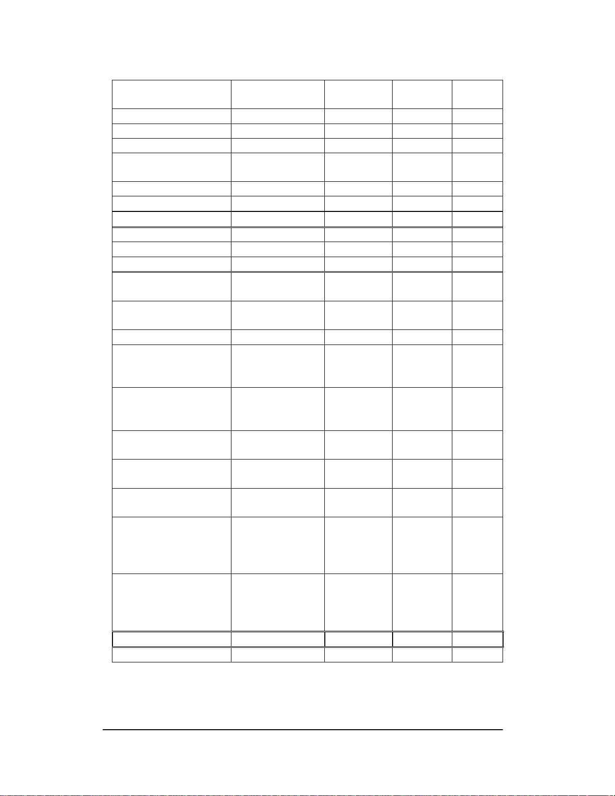
The Sub IDs of OME-PIO/PISO series card are given as follows:
OME-PIO/PISO series
card
OME-PIO-D144 (Rev4.0) 144 × D/I/O 80(5C80) 01 00
OME-PIO-D96 (Rev4.0) 96 × D/I/O 80(5880) 01 10
OME-PIO-D64 (Rev2.0) 64 × D/I/O 80(4080) 01 20
OME-PIO-D56 (Rev6.0) 24 × D/I/O +
OME-PIO-D48 (Rev2.0) 48 × D/I/O 80(0080) 01 30
OME-PIO-D24 (Rev6.0) 24 × D/I/O 80(C080) 01 40
OME-PIO-821 Multi-function 80 03 10
OME-PIO-DA16(Rev4.0) 16 × D/A 80(4180) 04(00) 00
OME-PIO-DA8 (Rev4.0) 8 × D/A 80(4180) 04(00) 00
OME-PIO-DA4 (Rev4.0) 4 × D/A 80(4180) 04(00) 00
OME-PISO-C64 (Rev4.0) 64 × isolated D/O
OME-PISO-A64 (Rev3.0) 64 × isolated D/O
OME-PISO-P64 (Rev4.0) 64 × isolated D/I 80(0280) 08(00) 10
OME-PISO-P32C32
(Rev5.0)
OME-PISO-P32A32
(Rev3.0)
OME-PISO-P8R8
(Rev2.0)
OME-PISO-P8SSR8AC
(Rev2.0)
OME-PISO-P8SSR8DC
(Rev2.0)
OME-PISO-730 (Rev2.0) 16 × DI +16 ×D/O +
OME-PISO-730A
(Rev3.0)
OME-PISO-813 (Rev2.0) 32 × isolated A/D 80(4280) 0A(02) 00
OME-PISO-DA2 (Rev5.0) 2 × isolated D/A 80(4280) 0B(03) 00
Description Sub_vendo
Old (New)
80(C080) 01 40
16 × D/I + 16*D/O
80(0280) 08(00) 00
(Current sinking)
80(8280) 08(00) 50
(Current sourcing)
32*isolated D/O
(Current sinking)
+32*isolated D/I
32*isolated D/O
(Current sourcing)
+32*isolated D/I
8 × isolated D/I +
8 × 220V relay
8 × isolated D/I +
8 × SSR /AC
8 × isolated D/I +
8 × SSR /DC
16 × isolated D/I +
16* isolated D/O
(Current sinking)
16 × DI +16 ×D/O +
16 × isolated D/I +
16* isolated D/O
(Current sourcing)
80(0280) 08(00) 20
80(8280) 08(00) 70
80(4200) 08(00) 30
80(4200) 08(00) 30
80(4200) 08(00) 30
80(C2FF) 08(00) 40
80(62FF) 08(00) 80
Sub_device
Old (New)
Sub_AUX
Note: If your board is a different version, it may also have different Sub IDs.
However this will present no actual problem. No matter which version of the
board you select, we offer the same function calls.
OME-PIO -DA16/8/4 User’s Manual (Ver. 2.1,Nov /2003) ----- 38
Page 41

3.1.2 PIO_GetConfigAddressSpace
PIO_GetConfigAddressSpace(wBoardNo,*wBase,*wIrq, *wSubVendor,
*wSubDevice,*wSubAux,*wSlotBus, *wSlotDevice)
• wBoardNo=0 to N Æ totally N+1 boards found by PIO_DriveInit(….)
• wBase Æ base address of the board control word
• wIrq Æ allocated IRQ channel number of this board
• wSubVendor Æ subVendor ID of this board
• wSubDevice Æ subDevice ID of this board
• wSubAux Æ subAux ID of this board
• wSlotBus Æ hardware slot ID1 of this board
• wSlotDevice Æ hardware slot ID2 of this board
The user can use this function to save resource information of all OME-
PIO/PISO cards installed in this system. Then the application program can control all
functions of OME-PIO/PISO series card directly.
The sample program source is given as follows:
/* step1: detect all OME-PIO-DA16/8/4 cards first */
wSubVendor=0x80; wSubDevice=4; wSubAux=0x00; /* for PIO_DA16/8/4 */
wRetVal=PIO_DriverInit(&wBoards, wSubVendor,wSubDevice,wSubAux);
printf("Threr are %d OME-PIO-DA16/8/4 Cards in this PC\n",wBoards);
/* step2: save resource of all OME-PIO-DA16/8/4 cards installed in this PC */
for (i=0; i<wBoards; i++)
{
PIO_GetConfigAddressSpace(i,&wBase,&wIrq,&t1,&t2,&t3,&t4,&t5);
printf("\nCard_%d: wBase=%x, wIrq=%x", i,wBase,wIrq);
wConfigSpace[i][0]=wBaseAddress; /* save all resource of this card */
wConfigSpace[i][1]=wIrq; /* save all resource of this card */
}
/* step3: control the OME-PIO-DA16/8/4 directly */
wBase=wConfigSpace[0][0];/* get base address the card_0 */
outport(wBase,1); /* enable all D/I/O operation of card_0 */
wBase=wConfigSpace[1][0];/* get base address the card_1 */
outport(wBase,1); /* enable all D/I/O operation of card_1 */
OME-PIO-DA16/8/4 User’s Manual (Ver. 2.1,Nov /2003) ----- 39
Page 42

3.1.3 Show_PIO_PISO
Show_PIO_PISO(wSubVendor,wSubDevice,wSubAux)
• wSubVendor Æ subVendor ID of board to find
• wSubDevice Æ subDevice ID of board to find
• wSubAux Æ subAux ID of board to find
This function will show a text string for these special subIDs. This text string is the
same as that defined in PIO.H
The demo program is given as follows:
wRetVal=PIO_DriverInit(&wBoards,0xff,0xff,0xff); /*find all PIO_PISO*/
printf("\nThrer are %d PIO_PISO Cards in this PC",wBoards);
if (wBoards==0 ) exit(0);
printf("\n-----------------------------------------------------");
for(i=0; i<wBoards; i++)
{
PIO_GetConfigAddressSpace(i,&wBase,&wIrq,&wSubVendor,
&wSubDevice,&wSubAux,&wSlotBus,&wSlotDevice);
printf("\nCard_%d:wBase=%x,wIrq=%x,subID=[%x,%x,%x],
SlotID=[%x,%x]",i,wBase,wIrq,wSubVendor,wSubDevice,
wSubAux,wSlotBus,wSlotDevice);
printf(" --> ");
ShowPioPiso(wSubVendor,wSubDevice,wSubAux);
}
OME-PIO-DA16/8/4 User’s Manual (Ver. 2.1,Nov /2003) ----- 40
Page 43

3.2 The Assignment of I/O Address
The plug & play BIOS will assign the proper I/O address to the OME-
PIO/PISO series card. If there is only one OME-PIO/PISO board, the user can
identify the board as card_0. If there are two OME-PIO/PISO boards in the system,
it will be difficult to identify which board is card_0? The software driver can support
16 boards max. Therefore the user can install 16 boards of OME-PIO/PSIO series in
one PC system. How to find the card_0 & card_1?
The simplest way to identify which card is card_0 is to use wSlotBus &
wSlotDevice as following:
1. Remove all OME-PIO-DA16/8/4 from this PC
2. Install one OME-PIO-DA16/8/4 into the PC’s PCI_slot1, run
PIO_PISO.EXE & record the wSlotBus1 & wSlotDevice1
3. Remove all OME-PIO-DA16/8/4 from this PC
4. Install one OME-PIO-DA16/8/4 into the PC’s PCI_slot2, run
PIO_PISO.EXE & record the wSlotBus2 & wSlotDevice2
5. Repeat (3) & (4) for all PCI_slot?, record all wSlotBus? & wSlotDevice?
The records may be as follows:
PC’s PCI slot WslotBus WSlotDevice
Slot_1 0 0x07
Slot_2 0 0x08
Slot_3 0 0x09
Slot_4 0 0x0A
PCI-BRIDGE
Slot_5 1 0x0A
Slot_6 1 0x08
Slot_7 1 0x09
Slot_8 1 0x07
The above procedure will record all wSlotBus? & wSlotDevice? in the PC. These
values will be mapped to this PC’s physical slot. This mapping will not be changed
for any PIO/PISO cards. So it can be used to identify the specified PIO/PISO card as
following:
Step 1: Record all wSlotBus? & wSlotDevice?
Step2: Use PIO_GetConfigAddressSpace(…) to get the specified card’s wSlotBus
& wSlotDevice
Step3: The user can identify the specified OME-PIO/PISO card if you compare
the wSlotBus & wSlotDevice in step2 to step1.
OME-PIO-DA16/8/4 User’s Manual (Ver. 2.1,Nov /2003) ----- 41
Page 44
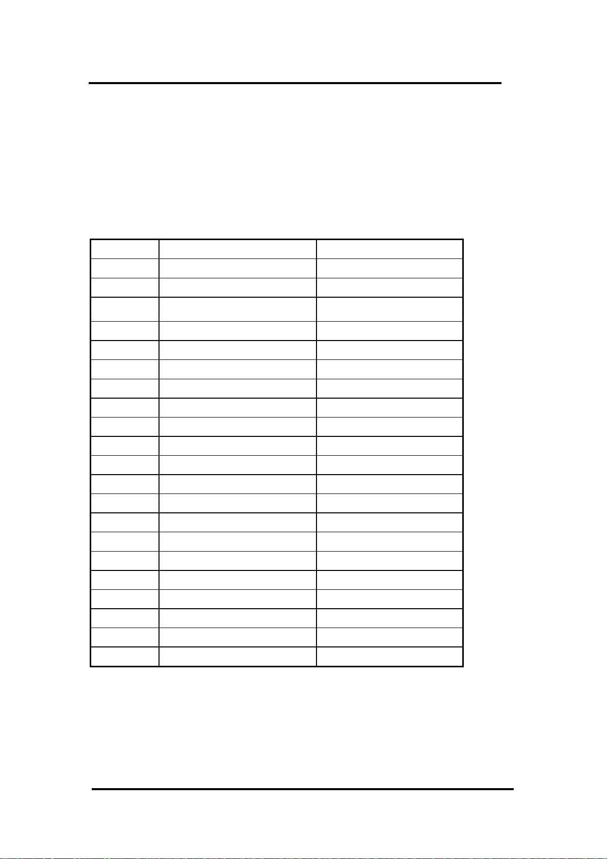
3.3 The I/O Address Map
The I/O addresses of OME-PIO/PISO series card are automatically
assigned by the main board ROM BIOS. The I/O address can also be re-
assigned by user. It is strongly recommended to the user to not change the
I/O address. The plug & play BIOS will assign proper I/O address to
each OME-PIO/PISO series card very well. The I/O addresses of the
OME-PIO-DA16/8/4 cards are given as follows:
Address Read Write
wBase+0 RESET\ control register Same
wBase+2 Aux control register Same
wBase+3 Aux data register Same
wBase+5 INT mask control register Same
wBase+7 Aux pin status register Same
wBase+0x2a INT polarity control register Same
wBase+0xc0 Read 8254-counter0 Write 8254-counter0
wBase+0xc4 Read 8254-counter1 Write 8254-counter1
wBase+0xc8 Read 8254-counter2 Write 8254-counter2
wBase+0xcc Read 8254 control word Write 8254 control word
wBase+0xe0 Read low byte of D/I DA_0 chip select
wBase+0xe4 Read high byte of D/I DA_1 chip select
wBase+0xe8 Read low byte of D/I DA_2 chip select
wBase+0xec Read high byte of D/I DA_3 chip select
wBase+0xf0 Read low byte of D/I Write low byte of D/A
wBase+0xf4 Read high byte of D/I Write high byte of D/A
wBase+0xf8 Read low byte of D/I Write low byte of D/O
wBase+0xfc Read high byte of D/I Write high byte of D/O
Note. Refer to Sec. 3.1 for more information about wBase.
OME-PIO-DA16/8/4 User’s Manual (Ver. 2.1,Nov /2003) ----- 42
Page 45

3.3.1. RESET\ Control Register
(Read/Write): wBase+0
Bit 7 Bit 6 Bit 5 Bit 4 Bit 3 Bit 2 Bit 1 Bit 0
Reserved Reserved Reserved Reserved Reserved Reserved Reserved RESET\
Note. Refer to Sec. 3.1 for more information about wBase.
When the PC is first power-up, the RESET\ signal is in Low-state. This will disable
all D/I/O operations. The user has to set the RESET\ signal to High-state before any
D/I/O command.
outportb(wBase,1); /* RESET\=High Æ all D/I/O are enable now */
outportb(wBase,0); /* RESET\=Low Æ all D/I/O are disable now */
3.3.2 AUX Control Register
(Read/Write): wBase+2
Bit 7 Bit 6 Bit 5 Bit 4 Bit 3 Bit 2 Bit 1 Bit 0
Aux7 Aux6 Aux5 Aux4 Aux3 Aux2 Aux1 Aux0
Note. Refer to Sec. 3.1 for more information about wBase.
Aux?=0Æ this Aux is used as a D/I
Aux?=1Æ this Aux is used as a D/O
When the PC is first power-on, All Aux? signal are in Low-state. All Aux? are
designed as D/I for all PIO/PISO series. Please set all Aux? in D/I state.
3.3.3 AUX data Register
(Read/Write): wBase+3
Bit 7 Bit 6 Bit 5 Bit 4 Bit 3 Bit 2 Bit 1 Bit 0
Aux7 Aux6 Aux5 Aux4 Aux3 Aux2 Aux1 Aux0
Note. Refer to Sec. 3.1 for more information about wBase.
When the Aux? is used as D/O, the output state is controlled by this register.
This register is designed for feature extension, so do not control this register.
OME-PIO-DA16/8/4 User’s Manual (Ver. 2.1,Nov /2003) ----- 43
Page 46

3.3.4 INT Mask Control Register
(Read/Write): wBase+5
Bit 7 Bit 6 Bit 5 Bit 4 Bit 3 Bit 2 Bit 1 Bit 0
0 0 0 0 0 0 EN1 EN0
Note. Refer to Sec. 3.1 for more information about wBase.
EN0=0Æ disable INT0 as a interrupt signal (default)
EN0=1Æ enable INT0 as a interrupt signal
EN1=0Æ disable INT1 as a interrupt signal (default)
EN1=1Æ enable INT1 as a interrupt signal
outportb(wBase+5,0); /* disable all interrupts */
outportb(wBase+5,1); /* enable interrupt of INT0 */
outportb(wBase+5,2); /* enable interrupt of INT1 */
outportb(wBase+5,3); /* enable all two channels of interrupt */
Refer to the following demo programs for more information:
DEMO3.C & DEMO4.C Æ single interrupt source
DEMO5.C & DEMO6.C Æ multiple interrupt sources
OME-PIO-DA16/8/4 User’s Manual (Ver. 2.1,Nov /2003) ----- 44
Page 47

3.3.5 Aux Status Register
(Read/Write): wBase+7
Bit 7 Bit 6 Bit 5 Bit 4 Bit 3 Bit 2 Bit 1 Bit 0
Aux7 Aux6 Aux5 Aux4 Aux3 Aux2 Aux1 Aux0
Note. Refer to Sec. 3.1 for more information about wBase.
Aux0=INT0, Aux1=INT1, Aux2~3=controll EEPROM, Aux7~4=Aux-ID. Refer
to Sec. 4.1 for more information. The Aux 0~1 are used as interrupt sources. The
interrupt service routine has to read this register for interrupt source identification.
Refer to Sec. 2.3 for more information.
3.3.6 Interrupt Polarity Control Register
(Read/Write): wBase+0x2A
Bit 7 Bit 6 Bit 5 Bit 4 Bit 3 Bit 2 Bit 1 Bit 0
0 0 0 0
Note. Refer to Sec. 3.1 for more information about wBase.
INV0/1=0Æ select the inverted signal from INT0/1
INV0/1=1Æ select the non-inverted signal from INT0/1
outportb(wBase+0x2a,0); /* select the inverted input from all 2 channels */
outportb(wBase+0x2a,3); /* select the non-inverted input from all 2 channels */
outportb(wBase+0x2a,2); /* select the inverted input of INT0 */
/* select the non-inverted input from the others */
× ×
INV1 INV0
Refer to Sec. 2.3 for more information.
Refer to DEMO3/4/5/6.C for more information.
OME-PIO-DA16/8/4 User’s Manual (Ver. 2.1,Nov /2003) ----- 45
Page 48

3.3.7 Digital Input
(Read): wBase+0xf8 Æ Low byte of D/I port
Bit7 Bit6 Bit5 Bit4 Bit3 Bit2 Bit1 Bit0
DI7 DI6 DI5 DI4 DI3 DI2 DI1 DI0
(Read): wBase+0xfc Æ High byte of D/I port
Bit7 Bit6 Bit5 Bit4 Bit3 Bit2 Bit1 Bit0
DI15 DI14 DI13 DI12 DI11 DI10 DI9 DI8
Note. Refer to Sec. 3.1 for more information about wBase.
wDiLoByte = inportb(wBase+0xf8); /* read D/I states (DI 7~DI0) */
wDiHiByte = inportb(wBase+0xfc); /* read D/I states (DI15~DI8) */
wDiValue = (wDiHiByte<<8)|wDiLoByte;
Refer to DEMO2.C for more information.
3.3.8 Digital Output
(Write): wBase+0xf8 Æ Low byte of D/O port
Bit7 Bit6 Bit5 Bit4 Bit3 Bit2 Bit1 Bit0
DO7 DO6 DO5 DO4 DO3 DO2 DO1 DO0
(Write): wBase+0xfc Æ High byte of D/O port
Bit7 Bit6 Bit5 Bit4 Bit3 Bit2 Bit1 Bit0
DO15 DO14 DO13 DO12 DO11 DO10 DO9 DO8
Note. Refer to Sec. 3.1 for more information about wBase.
outportb(wBase+0xf8,wDoValue); /* Control the DO state (DO 7~DO0) */
outportb(wBase+0xfc,wDoValue>>8); /* Control the DO state (DO15~DO8) */
Refer to DEMO1/2.C for more information.
OME-PIO-DA16/8/4 User’s Manual (Ver. 2.1,Nov /2003) ----- 46
Page 49

3.3.9 Read/Write 8254
(Read/Write): wBase+0xc0=8254-counter-0
(Read/Write): wBase+0xc4=8254-counter-1
(Read/Write): wBase+0xc8=8254-counter-2
(Read/Write): wBase+0xcc=8254 control word
8254 control word
SC1 SC0 RL1 RL0 M2 M1 M0 BCD
BCD: 0: binary count 1: BCD count
M2,M1,M0: 000:mode0 interrupt on terminal count
001:mode1 programmable one-shot
010:mode2 rate generator
011:mode3 square-wave generator
100:mode4 software triggered pulse
101:mode5 hardware triggered pulse
RL1,RL0: 00: counter latch instruction
01: read/write low counter byte only
10: read/write high counter byte only
11: read/write low counter byte first, then high counter byte
SC1,SC0: 00: counter0
01: counter1
10: counter2
11: read -back command
WORD pio_da16_c0(char cConfig, char cLow, char cHigh)/*COUNTER_0 */
{
outportb(wBase+0xcc,cConfig);
outportb(wBase+0xc0,cLow);
outportb(wBase+0xc0,cHigh);
return(NoError);
}
WORD pio_da16_c1(char cConfig, char cLow, char cHigh)/*COUNTER_1 */
{
outportb(wBase+0xcc,cConfig);
outportb(wBase+0xc4,cLow);
outportb(wBase+0xc4,cHigh);
return(NoError);
}
WORD pio_da16_c2(char cConfig, char cLow, char cHigh)/*COUNTER_2 */
{
outportb(wBase+0xcc,cConfig);
outportb(wBase+0xc8,cLow);
outportb(wBase+0xc8,cHigh);
return(NoError);
}
OME-PIO-DA16/8/4 User’s Manual (Ver. 2.1,Nov /2003) ----- 47
Page 50

3.3.10 D/A Select
There are 4/2/1 D/A converters in respective OME-PIO-DA16/8/4 card. It is
necessary to select which D/A converter is desired after D/A data had be sent. D/A
channels allocate as follows:
Write A1 A0
WBase+0xe0
DA_0
Wbase+0xe4
DA_1
Wbase+0xe8
DA_2
Wbase+0xec
DA_3
0 0 D/A output channel 0
0 1 D/A output channel 1
1 0 D/A output channel 2
1 1 D/A output channel 3
0 0 D/A output channel 4
0 1 D/A output channel 5
1 0 D/A output channel 6
1 1 D/A output channel 7
0 0 D/A output channel 8
0 1 D/A output channel 9
1 0 D/A output channel10
1 1 D/A output channel11
0 0 D/A output channel12
0 1 D/A output channel13
1 0 D/A output channel14
1 1 D/A output channel15
Note: Refer to Sec.3.3.11 for more information about A1, A0
outportb(wBase+0xf0,wDaValue); /* output low byte of D/A data */
outportb(wBase+0xf4,(wDaValue>>8)|0x02); /* output high byte of D/A data and */
/* select channel 2 on this converter */
outportb(wBase+0xe0,0); /* select DA_0 */
/* after this procedure wDaValue will */
/* be sent to channel_2 */
Refer to DEMO6.C, DEMO7.C, DEMO8.C and DEMO9.C for more
information.
OME-PIO-DA16/8/4 User’s Manual (Ver. 2.1,Nov /2003) ----- 48
Page 51
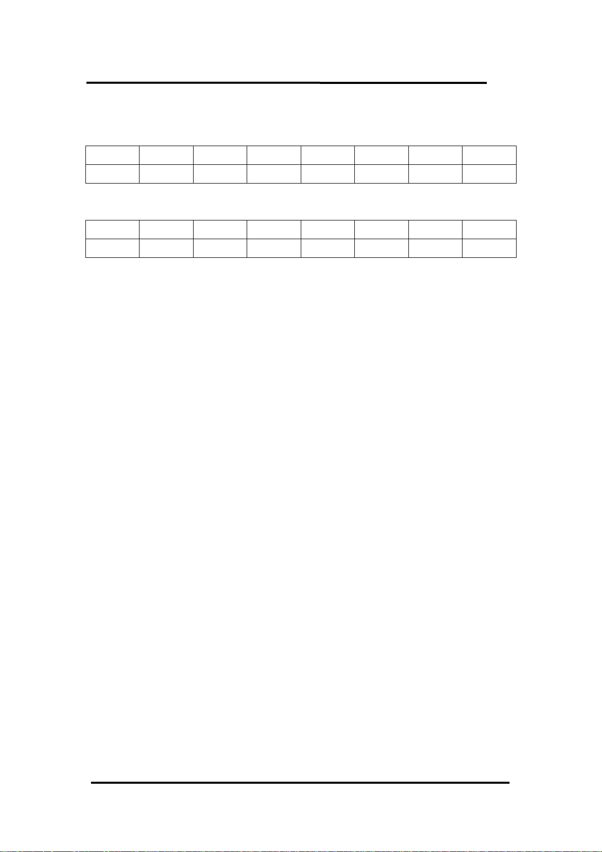
3.3.11 D/A Data Output
(write):wBase+0xf0
Bit7 Bit6 Bit5 Bit4 Bit3 Bit2 Bit1 Bit0
D7 D6 D5 D4 D3 D2 D1 D0
(write):wBase+0xf4
Bit7 Bit6 Bit5 Bit4 Bit3 Bit2 Bit1 Bit0
A1 A0 D13 D12 D11 D10 D9 D8
Note: Refer to Sec.3.3.10 For more information about A1,A2
Each D/A converter has four channels of analog output. When write data to D/A
converter has to indicate which channel is desire by A1 and A0.
D/A programming sequence:
1. Send data to D/A converter. (This data will be buffered)
2. Select D/A converter. (Start convert)
outportb(wBase+0xf0,wDaValue); /* output low byte of D/A data */
outportb(wBase+0xf4,(wDaValue>>8)|0x02); /* output high byte of D/A data and */
/* select channel 2 on this converter */
outportb(wBase+0xe0,0); /* select DA_0 */
/* after this procedure wDaValue will */
/* be sent to channel_2 */
pio_da16_da(2,wDaValue); /* send wDaValue to channel_2 */
void pio_da16_da(char cChannel_no,int iVal)
{
iVal=iVal+(cChannel_no%4)*0x4000; /* cChannel_no : 0 - 15 */
outportb(wBase+0xf0,iVal); /* iVal : 0x0000 - 0x3fff */
outportb(wBase+0xf4,(iVal>>8));
outportb(wBase+0xe0+4*(cChannel_no/4),0xff);
}
Refer to DEMO6.C, DEMO7.C, DEMO8.C and DEMO9.C for more
information.
OME-PIO-DA16/8/4 User’s Manual (Ver. 2.1,Nov /2003) ----- 49
Page 52

4. Demo Program
It is recommended to read the release note first. All importance information will be
given in release note as follows:
1. Where you can find the software driver & utility?
2. How to install software & utility?
3. Where is the diagnostic program?
4. FAQ
The demo programs are provided on the software floppy disk or CD. After the
software installation, the driver will be installed into disk as follows:
• \TC\*.* Æ for Turbo C 2.xx or above
• \MSC\*.* Æ for MSC 5.xx or above
• \BC\*.* Æ for BC 3.xx or above
• \TC\LIB\*.* Æ for TC library
• \TC\DEMO\*.* Æ for TC demo program
• \TC\LIB\Large\*.* Æ TC large model library
• \TC\LIB\Huge\*.* Æ TC huge model library
• \TC\LIB\Large\PIO.H Æ TC declaration file
• \TC\\LIB\Large\TCPIO_L.LIB Æ TC large model library file
• \TC\LIB\Huge\PIO.H Æ TC declaration file
• \TC\\LIB\Huge\TCPIO_H.LIB Æ TC huge model library file
• \MSC\LIB\Large\PIO.H Æ MSC declaration file
• \MSC\LIB\Large\MSCPIO_L.LIB Æ MSC large model library file
• \MSC\LIB\Huge\PIO.H Æ MSC declaration file
• \MSC\\LIB\Huge\MSCPIO_H.LIB Æ MSC huge model library file
• \BC\LIB\Large\PIO.H Æ BC declaration file
• \BC\LIB\Large\BCPIO_L.LIB Æ BC large model library file
• \BC\LIB\Huge\PIO.H Æ BC declaration file
• \BC\\LIB\Huge\BCPIO_H.LIB Æ BC huge model library file
NOTE: The library is validated for all OME-PIO/PISO series cards.
OME-PIO-DA16/8/4 User’s Manual (Ver. 2.1,Nov /2003) ----- 50
Page 53

Demo programs:
DEMO1.EXE: D/O demo program
DEMO2.EXE: D/I/O demo program
DEMO3.EXE: Single interrupt source (initial high)
DEMO4.EXE: Single interrupt source (initial low)
DEMO5.EXE: Two interrupt source
DEMO6.EXE: Waveform generator without calibration
DEMO7.EXE: Waveform generator with calibration
DEMO8.EXE: D/A hex value output without calibration
DEMO9.EXE: D/A hex value output with calibration
DEMO10.EXE: Save EEPROM data to file
DEMO11.EXE: Download EEPROM data from file
DEMO12.EXE: User software calibration
DEMO13.EXE: Factory calibration
Note: Not all demo programs may be listed in this manual. Please refer to
software floppy disk or CD.
OME-PIO-DA16/8/4 User’s Manual (Ver. 2.1,Nov /2003) ----- 51
Page 54

4.1 PIO_PISO
/* ------------------------------------------------------------ */
/* Find all OME-PIO_PISO series cards in this PC system */
/* step 1 : plug all OME-PIO_PISO cards into PC */
/* step 2 : run PIO_PISO.EXE */
/* ------------------------------------------------------------ */
#include "PIO.H"
WORD wBase,wIrq;
WORD wBase2,wIrq2;
int main()
{
int i,j,j1,j2,j3,j4,k,jj,dd,j11,j22,j33,j44;
WORD wBoards,wRetVal;
WORD wSubVendor,wSubDevice,wSubAux,wSlotBus,wSlotDevice;
char c;
float ok,err;
clrscr();
wRetVal=PIO_DriverInit(&wBoards,0xff,0xff,0xff); /*for PIO-PISO*/
printf("\nThrer are %d PIO_PISO Cards in this PC",wBoards);
if (wBoards==0 ) exit(0);
printf("\n-----------------------------------------------------");
for(i=0; i<wBoards; i++)
{
PIO_GetConfigAddressSpace(i,&wBase,&wIrq,&wSubVendor,
&wSubDevice,&wSubAux,&wSlotBus,&wSlotDevice);
printf("\nCard_%d:wBase=%x,wIrq=%x,subID=[%x,%x,%x],
SlotID=[%x,%x]",i,wBase,wIrq,wSubVendor,wSubDevice,
wSubAux,wSlotBus,wSlotDevice);
printf(" --> ");
ShowPioPiso(wSubVendor,wSubDevice,wSubAux);
}
PIO_DriverClose();
}
NOTE: the PIO_PISO.EXE is valid for all PIO/PISO cards. The user can execute
the PIO_PISO.EXE to get the following information:
• List all PIO/PISO cards installed in this PC
• List all resources allocated to every PIO/PISO cards
• List the wSlotBus & wSlotDevice for specified OME-PIO/PISO card
identification.
(Refer to Sec. 3.2 for more information)
OME-PIO-DA16/8/4 User’s Manual (Ver. 2.1,Nov /2003) ----- 52
Page 55
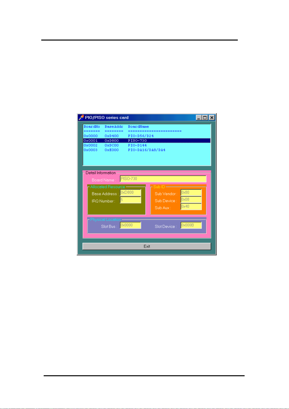
4.1.1 PIO_PISO.EXE for Windows
User can find this utility on the CD or the floppy disk. It is useful for all OME-
PIO/PISO series card.
After executing the utility, detail information for all OME-PIO/PISO cards that
installed in the PC will be show as follows:
OME-PIO-DA16/8/4 User’s Manual (Ver. 2.1,Nov /2003) ----- 53
Page 56

4.2 DEMO1
/* DEMO1 : D/O demo for OME-PIO-DA16/8/4
*/
/* step1 : Run DEMO1.EXE */
/* step2 : Check the LEDs of OME-DB-24C will turn on sequentially
*/
/* -------------------------------------------------------------- */
#include "PIO.H"
void pio_da16_do(WORD wDo);
WORD wBase,wIrq;
int main()
{
int i,j;
WORD wBoards,wRetVal,t1,t2,t3,t4,t5,t6;
WORD wSubVendor,wSubDevice,wSubAux,wSlotBus,wSlotDevice;
clrscr();
/* step1 : find address-mapping of PIO/PISO cards */
wRetVal=PIO_DriverInit(&wBoards,0x80,0x04,0x00);/*for OME-PIODA16/8/4*/
printf("\n(1) Threr are %d OME-PIO-DA16/8/4 Cards in this
PC",wBoards);
if ( wBoards==0 ) exit(0);
printf("\n\n-------------- The Configuration Space --------------");
for(i=0;i<wBoards;i++)
{
PIO_GetConfigAddressSpace(i,&wBase,&wIrq,&wSubVendor,&wSubDevice,
&wSubAux,&wSlotBus,&wSlotDevice);
printf("\nCard_%d: wBase=%x,wIrq=%x,subID=[%x,%x,%x],
SlotID=[%x,%x]",i,wBase,wIrq,wSubVendor,wSubDevice,wSubAux,
wSlotBus,wSlotDevice);
printf(" --> ");
ShowPioPiso(wSubVendor,wSubDevice,wSubAux);
}
PIO_GetConfigAddressSpace(0,&wBase,&wIrq,&t1,&t2,&t3,&t4,&t5);
/* select card_0 */
/* step2 : enable all D/I/O port */
outportb(wBase,1); /* /RESET -> 1 */
printf("\n\n(2) DEMO1 D/O test");
j=1;
for(;;)
{
gotoxy(1,8);
pio_da16_do(j);
printf("\nDO ==> %4x",j);
delay(10000);
if (kbhit()!=0) break;
j=j<<1; j=j&0x0ffff;if (j==0) j=1;
}
PIO_DriverClose();
}
/* -------------------------------------------------------------- */
void pio_da16_do(WORD wDo)
{
outportb(wBase+0xf8,wDo); /* 0xf8 : low byte of DO port */
outportb(wBase+0xfc,(wDo>>8)); /* 0xfc : high byte of DO port */
}
OME-PIO-DA16/8/4 User’s Manual (Ver. 2.1,Nov /2003) ----- 54
Page 57

4.3 DEMO2
/* DEMO2 : D/I/O demo for OME-PIO-DA16/8/4
*/
/* step1 : Connect CON1 & CON2 with a 20-pin 1 to 1 flat cable */
/* step2 : Run DEMO2.EXE */
/* -------------------------------------------------------------- */
#include "PIO.H"
void pio_da16_di(WORD *wDi);
void pio_da16_do(WORD wDo);
WORD wBase,wIrq;
int main()
{
int i,j,k;
WORD wBoards,wRetVal,t1,t2,t3,t4,t5,t6;
WORD wSubVendor,wSubDevice,wSubAux,wSlotBus,wSlotDevice;
clrscr();
/* step1 : find address-mapping of PIO/PISO cards */
.
.
/* step2 : enable all D/I/O port */
outportb(wBase,1); /* /RESET -> 1 */
printf("\n\n(2) DEMO2 D/I/O test");
j=1;
for(;;)
{
pio_da16_do(j);
pio_da16_di(&k);
gotoxy(1,9);
printf("DO = %4x , DI = %4x",j,k);
if (k!=j) printf(" <-- Test Error ");
else printf(" <-- Test Ok ");
j++; j=j&0x0ffff;if (j==0) j=1;
if (kbhit()!=0) break;
}
PIO_DriverClose();
}
/* -------------------------------------------------------------- */
void pio_da16_di(WORD *wDi)
{
int in_l,in_h;
in_l=inportb(wBase+0xe0)&0x0ff;
in_h=inportb(wBase+0xe4)&0x0ff;
(*wDi)=(in_h<<8)+in_l;
}
/* -------------------------------------------------------------- */
void pio_da16_do(WORD wDo)
{
outportb(wBase+0xf8,wDo); /* 0xf8 : low byte of DO port */
outportb(wBase+0xfc,(wDo>>8)); /* 0xfc : high byte of DO port */
}
OME-PIO-DA16/8/4 User’s Manual (Ver. 2.1,Nov /2003) ----- 55
Page 58

4.4 DEMO3
/* DEMO3 : INT_CHAN_1, timer interrupt demo (initial high) */
/* (It is designed to be a machine independent timer) */
/* step1 : Run DEMO3.EXE */
/* -------------------------------------------------------------- */
#include "PIO.H"
#define A1_8259 0x20
#define A2_8259 0xA0
static void interrupt irq_service();
void pio_da16_c0(char cConfig, char cLow, char cHigh);
void pio_da16_c1(char cConfig, char cLow, char cHigh);
void pio_da16_c2(char cConfig, char cLow, char cHigh);
void init_int1_high();
WORD wBase,wIrq;
int COUNT_L,COUNT_H,irqmask,now_int_state;
int main()
{
int i,j;
WORD wBoards,wRetVal,t1,t2,t3,t4,t5,t6;
WORD wSubVendor,wSubDevice,wSubAux,wSlotBus,wSlotDevice;
clrscr();
/* step1 : find address-mapping of PIO/PISO cards */
.
.
/* step2 : enable all D/I/O port */
outportb(wBase,1); /* /RESET -> 1 */
printf("\n\n(2) DEMO3 Interrupt (1Hz) test");
init_int1_high(); /* interrupt initialize, INT1 is high now */
COUNT_L=0;COUNT_H=0;
printf("\n\n*** Show the count of Low_pulse ***\n");
for (;;)
{
gotoxy(1,10);
printf("\nINT count = %d",COUNT_L);
if (kbhit()!=0) break;
}
outportb(wBase+5,0); /* disable all interrupt */
PIO_DriverClose();
}
/* Use INT_CHAN_1 as internal interrupt signal */
void init_int1_high()
{
DWORD dwVal;
disable();
outportb(wBase+5,0); /* disable all interrupt */
if (wIrq<8)
{
irqmask=inportb(A1_8259+1);
outportb(A1_8259+1,irqmask & (0xff ^ (1 << wIrq)));
setvect(wIrq+8, irq_service);
}
else
{
irqmask=inportb(A1_8259+1);
outportb(A1_8259+1,irqmask & 0xfb); /* IRQ2 */
irqmask=inportb(A2_8259+1);
outportb(A2_8259+1,irqmask & (0xff ^ (1 << (wIrq-8))));
setvect(wIrq-8+0x70, irq_service);
}
/* CLK source = 4 MHz */
pio_da16_c1(0x76,0x90,0x01); /* COUNTER1, mode3, div 400 */
pio_da16_c2(0xb6,0x10,0x27); /* COUNTER2, mode3, div 10000 */
OME-PIO-DA16/8/4 User’s Manual (Ver. 2.1,Nov /2003) ----- 56
Page 59

/* program Cout2 1Hz */
/* note : the 8254 need extra 2-clock for initialization */
for (;;)
{
if ((inportb(wBase+7)&2)==2) break; /* wait Cout2 = high */
}
/* note : Cout2 = high, INV1 must select the inverted Cout2 */
/* --> INT_CHAN_1 = !Cout2 = init_low, active_high */
outportb(wBase+0x2a,0); /* INV1 = 0, inverted Cout2 */
now_int_state=1; /* now Cout2 is high */
outportb(wBase+5,2); /* EN1 = 1, enable INT_CHAN_1 */
/* as interrupt source */
enable();
}
/* -------------------------------------------------------------- */
void interrupt irq_service()
{
if (now_int_state==1) /* now INT1(Cout2) changed to low */
{ /* --> INT_CHAN_1=!INT1=high now */
COUNT_L++; /* find a low pulse (INT1) */
if((inportb(wBase+7)&2)==0) /* INT1 is still fixed in low -> */
{ /* need to generate a high pulse */
outportb(wBase+0x2a,2); /* INV1 select non-inverted input */
/* INT_CHAN_1=INT1=low --> */
/* INT_CHAN_1 generate high pulse */
now_int_state=0; /* now INT1=low */
}
else now_int_state=1; /* now INT1=high */
/* don't have to gen. high pulse */
}
else /* now INT1(Cout2) changed to high */
{ /* --> INT_CHAN_1=INT1=high now */
COUNT_H++; /* find a low pulse (INT1) */
if((inportb(wBase+7)&2)==2) /* INT1 is still fixed in high -> */
{ /* need to generate a high pulse */
outportb(wBase+0x2a,0); /* INV1 select inverted input */
/* INT_CHAN_1=!INT1=low --> */
/* INT_CHAN_1 generate high_pulse */
now_int_state=1; /* now INT1=high */
}
else now_int_state=0; /* now INT1=low */
/* don't have to gen. high pulse */
}
if (wIrq>=8) outportb(A2_8259,0x20);
outportb(A1_8259,0x20);
}
/* -------------------------------------------------------------- */
void pio_da16_c0(char cConfig, char cLow, char cHigh) /* COUNTER0 */
{
outportb(wBase+0xcc,cConfig);
outportb(wBase+0xc0,cLow);
outportb(wBase+0xc0,cHigh);
}
OME-PIO-DA16/8/4 User’s Manual (Ver. 2.1,Nov /2003) ----- 57
Page 60

4.5 DEMO5
/* DEMO5 : INT_CHAN_0 & INT_CHAN_1 timer interrupt demo */
/* (It is designed to be a machine independent timer) */
/* step1 : Run DEMO5.EXE */
/* -------------------------------------------------------------- */
#include "PIO.H"
#define A1_8259 0x20
#define A2_8259 0xA0
static void interrupt irq_service();
WORD wBase,wIrq;
int irqmask,now_int_state,new_int_state,int_c;
int INT0_L,INT0_H,INT1_L,INT1_H;
int b0,b1,invert;
int main()
{
int i,j;
WORD wBoards,wRetVal,t1,t2,t3,t4,t5,t6;
WORD wSubVendor,wSubDevice,wSubAux,wSlotBus,wSlotDevice;
clrscr();
/* step1 : find address-mapping of PIO/PISO cards */
.
.
/* step2 : enable all D/I/O port */
outportb(wBase,1); /* /RESET -> 1 */
printf("\n\n(2) DEMO5 Interrupt test");
init_high(); /* interrupt initialize, INT_CHAN_0/1 is high now */
printf("\n\n*** Show the count of Low_pulse ***\n");
INT0_L=INT0_H=INT1_L=INT1_H=0;
for (;;)
{
gotoxy(1,10);
printf("\nINT0[%x,%x],INT1[%x,%x]",INT0_H,INT0_L,INT1_H,INT1_L);
if (kbhit()!=0) break;
}
outportb(wBase+5,0); /* disable all interrupt */
PIO_DriverClose();
}
/* Use INT_CHAN_0 & INT_CHAN_1 as internal interrupt signal */
void init_high()
{
DWORD dwVal;
disable();
outportb(wBase+5,0); /* disable all interrupt */
if (wIrq<8)
{
irqmask=inportb(A1_8259+1);
outportb(A1_8259+1,irqmask & (0xff ^ (1 << wIrq)));
setvect(wIrq+8, irq_service);
}
else
{
irqmask=inportb(A1_8259+1);
outportb(A1_8259+1,irqmask & 0xfb); /* IRQ2 */
irqmask=inportb(A2_8259+1);
outportb(A2_8259+1,irqmask & (0xff ^ (1 << (wIrq-8))));
setvect(wIrq-8+0x70, irq_service);
}
/* CLK source = 4 MHz */
pio_da16_c0(0x36,0x20,0x4e); /* COUNTER0, mode3, div 20000 */
/* program Cout0 200Hz */
pio_da16_c1(0x76,0x90,0x01); /* COUNTER1, mode3, div 400 */
pio_da16_c2(0xb6,0x64,0x00); /* COUNTER2, mode3, div 100 */
OME-PIO-DA16/8/4 User’s Manual (Ver. 2.1,Nov /2003) ----- 58
Page 61

/* program Cout2 100Hz */
/* note : the 8254 need extra 2-clock for initialization */
for (;;)
{
if ((inportb(wBase+7)&3)==3) break;/* wait Cout0&Cout2 = high */
}
/* note : Cout0/2 = high, INV0/1 must select the inverted Cout0/2 */
/* --> INT_CHAN_0 = !Cout0 = init_low, active_high */
/* --> INT_CHAN_1 = !Cout2 = init_low, active_high */
outportb(wBase+0x2a,0); /* INV0=0, INV1=0 inverted */
now_int_state=3; /* now Cout0 & Cout2 is high */
outportb(wBase+5,3); /* enable INT_CHAN_0/1 interrupt */
enable();
}
/* -------------------------------------------------------------- */
/* Note : 1.The hold_time of INT_CHAN_0 & INT_CHAN_1 must long */
/* enoug. */
/* 2.The ISR must read the interrupt status again to */
/* identify the active interrupt source. */
/* 3.The INT_CHAN_0 & INT_CHAN_1 can be active at the same */
/* time. */
/* -------------------------------------------------------------- */
void interrupt irq_service()
{
/* now ISR can not know which interrupt is active */
new_int_state=inportb(wBase+7)&0x03; /* read all interrupt */
/* signal state */
int_c=new_int_state^now_int_state; /* compare new_state to */
/* old_state */
if ((int_c&0x01)==1) /* INT_CHAN_0 is active */
{
if ((new_int_state&1)==0) /* INT0 change to low now */
{
INT0_L++;
}
else /* INT0 change to high now */
{
INT0_H++;
}
invert=invert^1; /* generate high_pulse */
}
if ((int_c&0x02)==2) /* INT_CHAN_1 is active */
{
if ((new_int_state&2)==0) /* INT1 change to low now */
{
INT1_L++;
}
else /* INT1 change to high now */
{
INT1_H++;
}
invert=invert^2; /* generate high_pulse */
}
now_int_state=new_int_state; /* update interrupt status */
outportb(wBase+0x2a,invert); /* generate a high pulse */
if (wIrq>=8) outportb(A2_8259,0x20);
outportb(A1_8259,0x20);
}
OME-PIO-DA16/8/4 User’s Manual (Ver. 2.1,Nov /2003) ----- 59
Page 62

4.6 DEMO8
/* DEMO8 : D/A Output without calibration */
/* step1 : Run DEMO8.EXE */
/* -------------------------------------------------------------- */
#include "PIO.H"
void pio_da16_da(int cChannel_no,int iVal);
WORD wBase,wIrq;
int main()
{
int i,j,k;
WORD wBoards,wRetVal,t1,t2,t3,t4,t5,t6;
WORD wSubVendor,wSubDevice,wSubAux,wSlotBus,wSlotDevice;
clrscr();
/* step1 : find address-mapping of PIO/PISO cards */
.
.
/* step2 : enable all D/I/O port */
outportb(wBase,0x11); /* /RESET -> 1 */
printf("\n\n(2) A/D Output without calibration test");
printf("\n\n (a) 1.23V Voltage output to each channel");
for (i=0; i<16; i++)
{
j=1.23*16383/20.0+8192;
pio_da16_da(i,j);
}
getch();
printf("\n\n (b) 1.23mA Current output to each channel");
for (i=0; i<16; i++)
{
j=1.23*8192/20+8191;
pio_da16_da(i,j);
}
getch();
outportb(wBase+5,0); /* disable all interrupt */
outportb(wBase+3,0); /* all D/O are Low */
outportb(wBase+2,0); /* all AUX as D/I */
PIO_DriverClose();
}
/* -------------------------------------------------------------- */
void pio_da16_da(int iChannel_no,int iVal)
{
iVal=iVal+(iChannel_no%4)*0x4000; /* iChannel_no : 0 - 15 */
outportb(wBase+0xf0,iVal); /* iVal : 0x0000 - 0x3fff */
outportb(wBase+0xf4,(iVal>>8));
outportb(wBase+0xe0+4*(iChannel_no/4),0xff);
}
OME-PIO-DA16/8/4 User’s Manual (Ver. 2.1,Nov /2003) ----- 60
Page 63

4.7 DEMO9
/* DEMO9 : D/A Output with calibration */
/* step1 : Run DEMO9.EXE */
/* -------------------------------------------------------------- */
#include "PIO.H"
void pio_da16_da(int cChannel_no,int iVal);
WORD wBase,wIrq;
WORD wN10V[16],wP10V[16],w00mA[16],w20mA[16],EEP;
float fDeltaV[16],fDeltaI[16];
int main()
{
int i,j,k;
WORD wBoards,wRetVal,t1,t2,t3,t4,t5,t6;
WORD wSubVendor,wSubDevice,wSubAux,wSlotBus,wSlotDevice;
clrscr();
/* step1 : find address-mapping of PIO/PISO cards */
.
.
/* step2 : enable all D/I/O port */
outportb(wBase,0x11); /* /RESET -> 1 */
outportb(wBase+2,0x1c); /* AUX 4/3/2 are D/O, othes D/I */
outportb(wBase+3,0); /* all D/O are Low */
printf("\n\n(2) A/D Output with calibration test");
for (i=0; i<64;i++)
{
if (i<16)
{
EEP_READ(i,&j,&k);
wN10V[i]=(j<<8)+k;
}
if ((i>=16)&&(i<32))
{
EEP_READ(i,&j,&k);
wP10V[i-16]=(j<<8)+k;
}
if ((i>=32)&&(i<48))
{
EEP_READ(i,&j,&k);
w00mA[i-32]=(j<<8)+k;
}
if (i>=48)
{
EEP_READ(i,&j,&k);
w20mA[i-48]=(j<<8)+k;
}
}
for (i=0; i<16; i++)
{
fDeltaV[i]=20.0/(wP10V[i]-wN10V[i]);
fDeltaI[i]=20.0/(w20mA[i]-w00mA[i]);
}
printf("\n\n (a) 1.23V Voltage output to each channel");
for (i=0; i<16; i++)
{
j=(1.23+10.0)/fDeltaV[i]+wN10V[i];
pio_da16_da(i,j);
OME-PIO-DA16/8/4 User’s Manual (Ver. 2.1,Nov /2003) ----- 61
Page 64

}
getch();
printf("\n\n (b) 1.23mA Current output to each channel");
for (i=0; i<16; i++)
{
j=1.23/fDeltaI[i]+w00mA[i];
pio_da16_da(i,j);
}
getch();
outportb(wBase+5,0); /* disable all interrupt */
outportb(wBase+3,0); /* all D/O are Low */
outportb(wBase+2,0); /* all AUX as D/I */
PIO_DriverClose();
}
OME-PIO-DA16/8/4 User’s Manual (Ver. 2.1,Nov /2003) ----- 62
Page 65

WARRANTY/DISCLAIMER
OMEGA ENGINEERING, INC. warrants this unit to be free of defects in materials and workmanship for a
period of 13 months from date of purchase. OMEGA’s WARRANTY adds an additional one (1) month
grace period to the normal one (1) year product warranty to cover handling and shipping time. This
ensures that OMEGA’s customers receive maximum coverage on each product.
If the unit malfunctions, it must be returned to the factory for evaluation. OMEGA’s Customer Service
Department will issue an Authorized Return (AR) number immediately upon phone or written request.
Upon examination by OMEGA, if the unit is found to be defective, it will be repaired or replaced at no
charge. OMEGA’s WARRANTY does not apply to defects resulting from any action of the purchaser,
including but not limited to mishandling, improper interfacing, operation outside of design limits,
improper repair, or unauthorized modification. This WARRANTY is VOID if the unit shows evidence of
having been tampered with or shows evidence of having been damaged as a result of excessive corrosion;
or current, heat, moisture or vibration; improper specification; misapplication; misuse or other operating
conditions outside of OMEGA’s control. Components which wear are not warranted, including but not
limited to contact points, fuses, and triacs.
OMEGA is pleased to offer suggestions on the use of its various products. However,
OMEGA neither assumes responsibility for any omissions or errors nor assumes liability for any
damages that result from the use of its products in accordance with information provided by
OMEGA, either verbal or written. OMEGA warrants only that the parts manufactured by it will be
as specified and free of defects. OMEGA MAKES NO OTHER WARRANTIES OR
REPRESENTATIONS OF ANY KIND WHATSOEVER, EXPRESS OR IMPLIED, EXCEPT THAT OF TITLE,
AND ALL IMPLIED WARRANTIES INCLUDING ANY WARRANTY OF MERCHANTABILITY AND
FITNESS FOR A PARTICULAR PURPOSE ARE HEREBY DISCLAIMED. LIMITATION OF
LIABILITY: The remedies of purchaser set forth herein are exclusive, and the total liability of
OMEGA with respect to this order, whether based on contract, warranty, negligence,
indemnification, strict liability or otherwise, shall not exceed the purchase price of the
component upon which liability is based. In no event shall OMEGA be liable for
consequential, incidental or special damages.
CONDITIONS: Equipment sold by OMEGA is not intended to be used, nor shall it be used: (1) as a “Basic
Component” under 10 CFR 21 (NRC), used in or with any nuclear installation or activity; or (2) in medical
applications or used on humans. Should any Product(s) be used in or with any nuclear installation or
activity, medical application, used on humans, or misused in any way, OMEGA assumes no responsibility
as set forth in our basic WARRANTY/ DISCLAIMER language, and, additionally, purchaser will indemnify
OMEGA and hold OMEGA harmless from any liability or damage whatsoever arising out of the use of the
Product(s) in such a manner.
RETURN REQUESTS/INQUIRIES
Direct all warranty and repair requests/inquiries to the OMEGA Customer Service Department. BEFORE
RETURNING ANY PRODUCT(S) TO OMEGA, PURCHASER MUST OBTAIN AN AUTHORIZED RETURN
(AR) NUMBER FROM OMEGA’S CUSTOMER SERVICE DEPARTMENT (IN ORDER TO AVOID
PROCESSING DELAYS). The assigned AR number should then be marked on the outside of the return
package and on any correspondence.
The purchaser is responsible for shipping charges, freight, insurance and proper packaging to prevent
breakage in transit.
FOR W
ARRANTY
RETURNS, please have the
following information available BEFORE
contacting OMEGA:
1. Purchase Order number under which the product
was PURCHASED,
2. Model and serial number of the product under
warranty, and
3. Repair instructions and/or specific problems
relative to the product.
FOR NON-W
ARRANTY
REPAIRS,
consult OMEGA
for current repair charges. Have the following
information available BEFORE contacting OMEGA:
1. Purchase Order number to cover the COST
of the repair,
2. Model and serial number of the product, and
3. Repair instructions and/or specific problems
relative to the product.
OMEGA’s policy is to make running changes, not model changes, whenever an improvement is possible. This affords
our customers the latest in technology and engineering.
OMEGA is a registered trademark of OMEGA ENGINEERING, INC.
© Copyright 2002 OMEGA ENGINEERING, INC. All rights reserved. This document may not be copied, photocopied,
reproduced, translated, or reduced to any electronic medium or machine-readable form, in whole or in part, without the
prior written consent of OMEGA ENGINEERING, INC.
Page 66

M4043/0104
Where Do I Find Everything I Need for
Process Measurement and Control?
OMEGA…Of Course!
Shop online at www.omega.com
TEMPERATURE
Thermocouple, RTD & Thermistor Probes, Connectors, Panels & Assemblies
Wire: Thermocouple, RTD & Thermistor
Calibrators & Ice Point References
Recorders, Controllers & Process Monitors
Infrared Pyrometers
PRESSURE, STRAIN AND FORCE
Transducers & Strain Gages
Load Cells & Pressure Gages
Displacement Transducers
Instrumentation & Accessories
FLOW/LEVEL
Rotameters, Gas Mass Flowmeters & Flow Computers
Air Velocity Indicators
Turbine/Paddlewheel Systems
Totalizers & Batch Controllers
pH/CONDUCTIVITY
pH Electrodes, Testers & Accessories
Benchtop/Laboratory Meters
Controllers, Calibrators, Simulators & Pumps
Industrial pH & Conductivity Equipment
DATA ACQUISITION
Data Acquisition & Engineering Software
Communications-Based Acquisition Systems
Plug-in Cards for Apple, IBM & Compatibles
Datalogging Systems
Recorders, Printers & Plotters
HEATERS
Heating Cable
Cartridge & Strip Heaters
Immersion & Band Heaters
Flexible Heaters
Laboratory Heaters
ENVIRONMENTAL
MONITORING AND CONTROL
Metering & Control Instrumentation
Refractometers
Pumps & Tubing
Air, Soil & Water Monitors
Industrial Water & Wastewater Treatment
pH, Conductivity & Dissolved Oxygen Instruments
 Loading...