

Page 1
Register
Table
®
User’s Guide
Shop online at
omega.com
®
e-mail: [email protected]
For latest product manuals:
omegamanual.info
OME-ET-7000 AND
OME-PET-7000 SERIES
Ethernet I/O Modules
Page 2

OMEGAnet®On-Line Service Internet e-mail
omega.com [email protected]
Servicing North America:
U.S.A.: ISO 9001 Certified
OMEGA Engineering, Inc., One Omega Drive
P.O. Box 4047, Stamford, CT 06907-0047 USA
Toll-Free: 1-800-826-6342
TEL: (203) 359-1660 FAX: (203) 359-7700
e-mail: [email protected]
For immediate technical or application assistance:
Canada:
976 Bergar, Laval (Quebec)
H7L 5A1, Canada
Toll-Free: 1-800-826-6342
TEL: (514) 856-6928 FAX: (514) 856-6886
e-mail: [email protected]
U.S.A. and Canada:
Sales Service: 1-800-826-6342/1-800-TC-OMEGA
Customer Service: 1-800-622-2378/1-800-622-BEST
®
®
Engineering Service: 1-800-872-9436/1-800-USA-WHEN
Servicing Asia
China: 1698 Yi Shan Road, Unit 102, Min Hang District
Shanghai, China 201103 P.R.C.
Hotline: 800 819 0559/400 619 0559
e-mail: [email protected]
Servicing Europe:
Benelux:
Toll-Free: 0800 099 3344
TEL: +31 20 347 21 21
FAX: +31 20 643 46 43
e-mail: [email protected]
Czech Republic:
Frystatska 184
733 01 Karviná, Czech Republic
Toll-Free: 0800-1-66342
TEL: +420-59-6311899
FAX: +420-59-6311114
e-mail: [email protected]
France:
Toll-Free: 0850 541038
TEL: 01 57 32 48 17
FAX: 01 57 32 48 18
e-mail: [email protected]
Germany/ Austria:
Daimlerstrasse 26
D-75392 Deckenpfronn, Germany
Toll-Free: 0800 8266342
TEL: +49 (0) 7056 9398-0
FAX: +49 (0) 7056 9398-29
e-mail: [email protected]
United Kingdom:
ISO 9001 Certified
OMEGA Engineering Ltd.
One Omega Drive
River Bend Technology Centre, Northbank
Irlam, Manchester M44 5BD England
Toll-Free: 0800-488-488
TEL: +44 (0) 161 777-6611
FAX: +44 (0) 161 777-6622
e-mail: [email protected]
Mexico/ Latin America:
TEL: 001 (203) 359-1660
FAX: 001 (203) 359-7700
®
e-mail: [email protected]
It is the policy of OMEGA Engineering, Inc. to comply with all worldwide safety and EMC/EMI regulations
that apply. OMEGA is constantly pursuing certification of its products to the European New Approach
Directives. OMEGA will add the CE mark to every appropriate device upon certification.
The information contained in this document is believed to be correct, but OMEGA accepts no liability for
any errors it contains, and reserves the right to alter specifications without notice.
WARNING: These products are not designed for use in, and should not be used for, human applications.
Page 3

| OME-ET-7000/OME-PET-7000 Series
Table of Contents
Preface ...................................................................................................................................... 1
About this Manual ........................................................................................................................... 1
Contents in this Manual .................................................................................................................. 2
OME-ET-7002/OME-PET-7002 ................................................................................................... 3
OME-ET-7015/OME-PET-7015 ................................................................................................... 8
OME-ET-7017/OME-PET-7017 ................................................................................................. 11
OME-ET-7017-10/OME-PET-7017-10 ...................................................................................... 16
OME-ET-7018Z/OME-PET-7018Z ............................................................................................ 21
OME-ET-7019/OME-PET-7019 ................................................................................................ 26
OME-ET-7019Z/OME-PET-7019Z ............................................................................................ 31
OME-ET-7026/OME-PET-7026 ................................................................................................. 37
OME-ET-7042/OME-PET-7042 ................................................................................................. 44
OME-ET-7044/OME-PET-7044 ................................................................................................. 46
OME-ET-7050/OME-PET-7050 ................................................................................................ 49
OME-ET-7051/OME-PET-7051 ................................................................................................. 52
OME-ET-7052/OME-PET-7052 ................................................................................................. 55
OME-ET-7053/OME-PET-7053 ................................................................................................. 58
OME-ET-7060/OME-PET-7060 ................................................................................................ 61
OME-ET-7067/OME-PET-7067 ................................................................................................. 64
Appendix ................................................................................................................................. 66
A. Analog Input Type and Data Format Table .............................................................................. 66
B. Analog Output Type and Data Format Table ............................................................................ 68
Page 4

P. 1
| OME-ET-7000/OME-PET-7000 Series
Preface
About this Manual
This manual is intended to be used as a reference for users who need to communicate
with the OME-ET-7000/OME-PET-7000 over a Modbus network.
This manual assumes that the user has some knowledge of commissioning and
programming of Modbus devices, including some knowledge of the Modbus protocol and
knowledge about your OME-ET-7000/OME-PET-7000 module.
This manual can be obtained from the companion CD:
CD:\OME-ET-7000_OME-PET-7000\Document\
Page 5
P. 2
| OME-ET-7000/OME-PET-7000 Series
Register fields
Description
Register
The register addresses
1. DEX: Decimal format
2. HEX: Hexadecimal format
Point
The number of the I/O point
Description
The function description for the register address
Data Format
The read or write range of the I/O data
Attribute
The access type
R: Read only
W: Write only
E: Save to the EEPROM
Factory Default
The factory default value after reset.
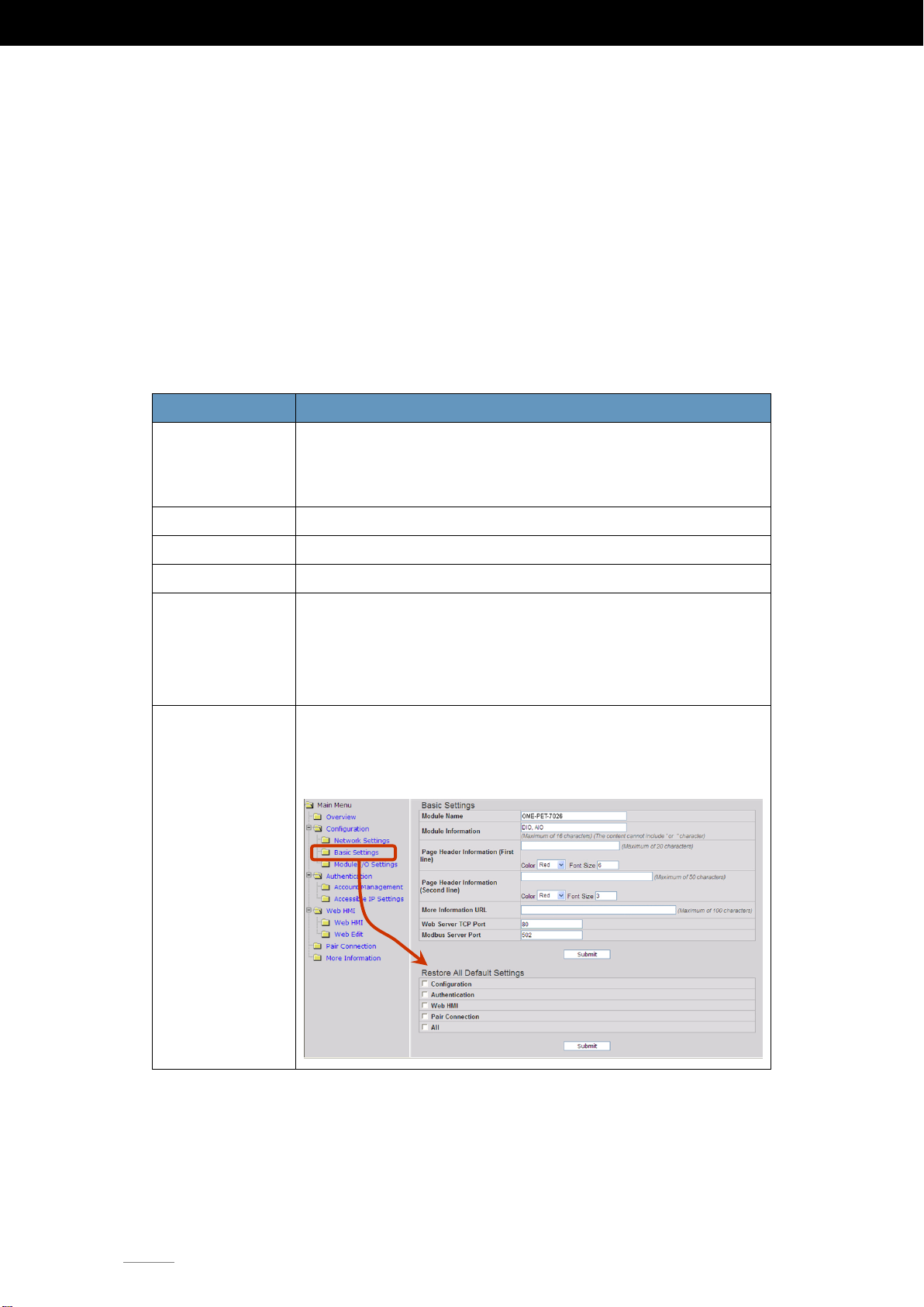
The reset function can be found in the
OME-ET-7000/OME-PET-7000 web page, as shown below.
Contents in this Manual
Each chapter contains the following information for each OME-ET-7000/OME-PET-7000
module:
I/O Specifications
Pin Assignments
Wire Connections
Modbus Register Table
The table below describes the properties of each field in a Modbus register table.
Page 6
P. 3
OME-ET-7002/OME-PET-7002
| OME-ET-7000/OME-PET-7000 Series
Analog Input
Input Channels
3 (Differential)
Input Type
+/-150 mV, +/-500 mV, +/-1 V, +/-5 V, +/-10 V,
0~20 mA, +/-20 mA, 4~20 mA
(jumper selectable)
Individual Channel Configuration
Yes
Resolution
Normal Mode
16-bit
Fast Mode
12-bit
Sampling Rate
Normal Mode
10 Samples/Sec. (Total)
Fast Mode
60 Samples/Sec. (Total)
Accuracy
Normal Mode
+/-0.1%
Fast Mode
+/-0.5% or better
Zero Drift
+/-20 uV/°C
Span Drift
+/-25 ppm/°C
Overvoltage Protection
240 Vrms
Overcurrent Protection
50 mA max. at 110 VDC/V
AC
max.
Input Impedance
Voltage
2 MΩ
Current
124 Ω
Common Mode Rejection
86 dB Min.
Normal Mode Rejection
100 dB
Digital Input/Counter
Input Channels
6
Type
Wet Contact (Sink or Source)
On Voltage Level
+10 VDC ~ +50 VDC
Off Voltage Level
+4V VDC max.
Input Impedance
10 KΩ, 0.5W
Counter
Channels
6
Max. Count
4,294,967,285 (32-bit)
Max. Input Frequency
100 Hz
Min. Pulse Width
5 ms
Overvoltage Protection
+50 VDC
Power Relay
Output Channels
3
Operating Voltage Range
Power Relay Form A (SPST N.O.)
Max. Load Current
5.0 A/Channel at 25°C
Operate Time
6 ms (Typical)
Release Time
3 ms (Typical)
Electrical Life (Resistive load)
VDE:
5 A @ 250 VAC 30,000ops
(10 ops/minute) at 75°C
5 A @ 30 VAC 70,000ops
(10 ops/minute) at 75°C
UL:
5 A @ 250 VAC/30 VDC 6,000 ops.
3 A @ 250 VAC/30 VDC 100,000 ops.
Mechanical Life
20,000,000 ops at no load (300 ops/minute)
Intra-module Isolation,
Field-to-Logic
3750 VDC
Power-on Value
Yes, Programmable
Safe Value
Yes, Programmable
OME-ET-7002/OME-PET-7002
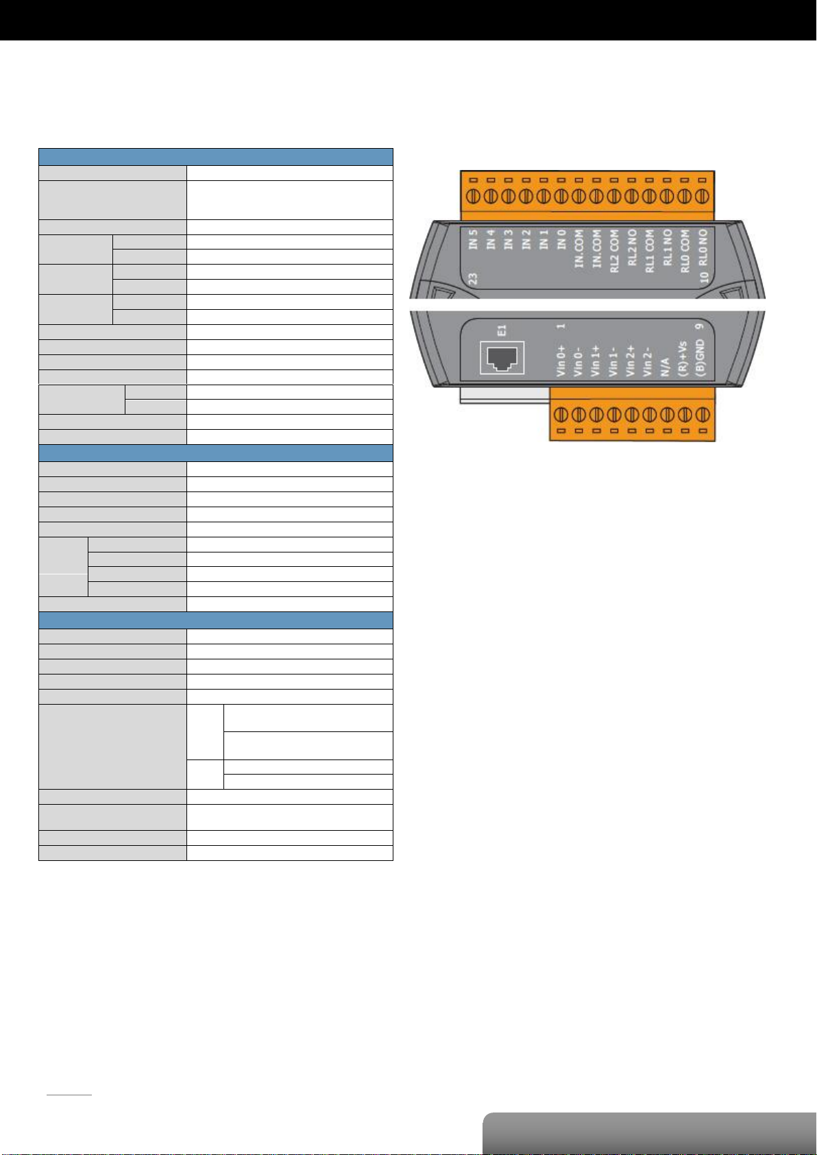
I/O Specifications
Pin Assignments
Page 7
P. 4
OME-ET-7002/OME-PET-7002
| OME-ET-7000/OME-PET-7000 Series
Voltage Input
Current Input
Digital Input/
Counter
Readback as 1
Readback as 0
+10 ~ +50 VDC
Open or <4 VDC
Sink
Source
Power Relay
ON State
Readback as 1
OFF State
Readback as 0
Relay Output
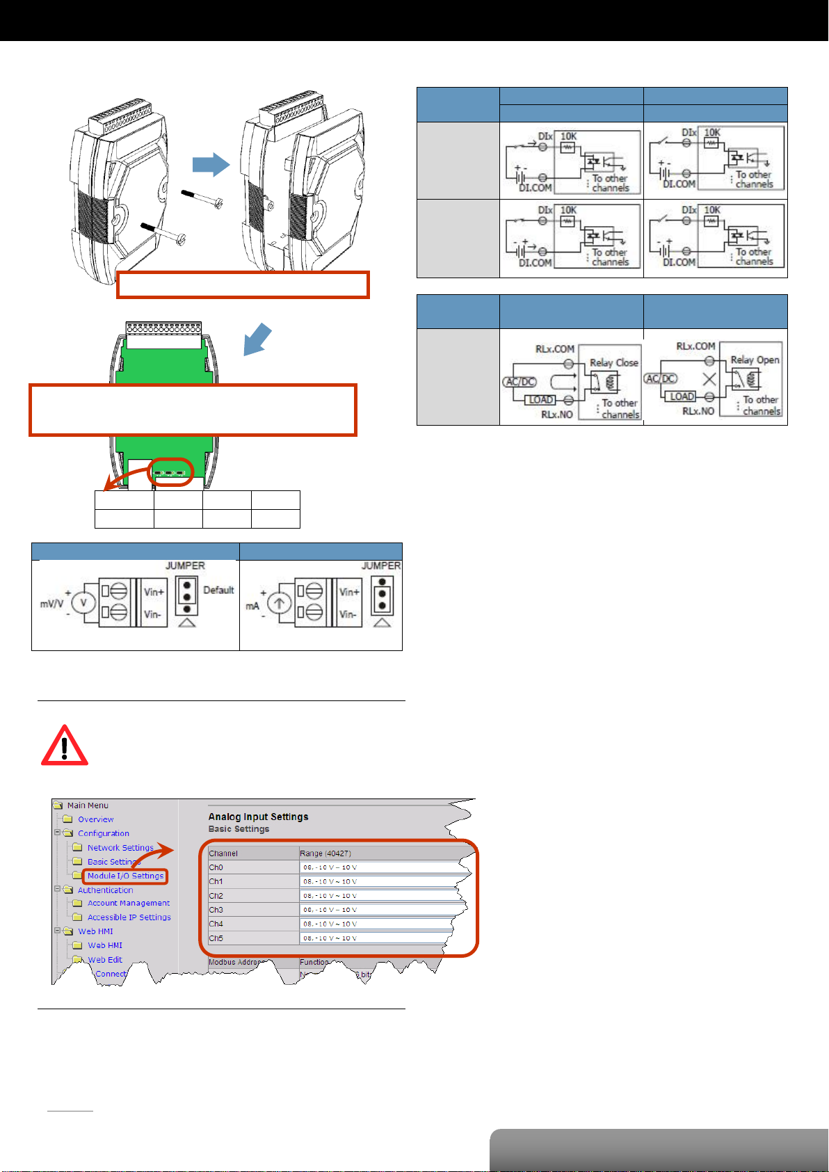
Remove the top case of the module.
The selection jumpers are next to the connector.
Refer to the table below to set the input type.
Channel
Vin0 ±
Vin1 ±
Vin2 ±
Jumper
J1
J2
J3
Voltage/Current Input Selection Jumper
Wire Connections
Tips & Warnings
The jumper settings of the input type for each AI
channel must correspond to the input range for
each AI channel of the web interface.
Page 8
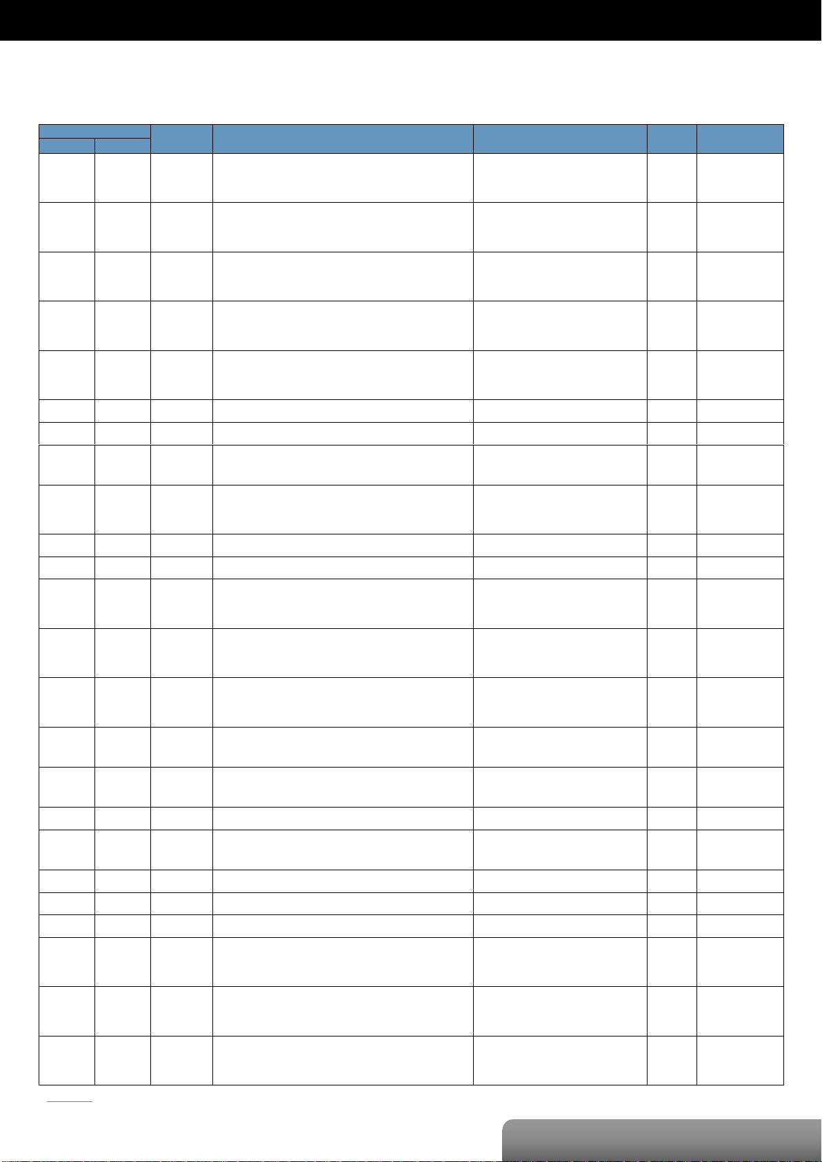
P. 5
| OME-ET-7000/OME-PET-7000 Series
OME-ET-7002/OME-PET-7002
Register
Points
Description
Data Format
Attribute
Factory Default
DEC
HEX
00000
:
00002
0000
:
0002
3
DO value
0: Off
1: On
R/W
-
00034
:
00039
0022
:
0027
6
Clear the DI counter value
1: Clear W -
00130
:
00135
0082
:
0087
6
Clear the DI latched value
1: Clear W -
00162
:
00164
00A2
:
00A4
3
Clear 1-ch historical AI max. value
1: Clear W -
00194
:
00196
00C2
:
00C4
3
Clear 1-ch historical AI min. value
1: Clear W -
00226
00E2
1
Reset the I/O settings to the factory default state
1: Reset W -
00233
00E9
1
Reboot the module
1: Reboot W -
00350
015E
1
Enable/Disable the DI latch function
0: Disable
1: Enable
R/W/E
0
00351
:
00356
015F
:
0164
6
Enable/Disable the DI counter function
0: Disable
1: Enable
R/W/E
0
00431
01AF
1
Save the DO power-on value to the EEPROM
1: Save
W/E
-
00432
01B0
1
Save the DO safe value to the EEPROM
1: Save
W/E
-
00435
:
00437
01B3
:
01B5
3
Enable/Disable the DO power-on value function
0: Disable
1: Enable
R/W
0
00515
:
00517
0203
:
0205
3
Enable/Disable the DO safe value function
0: Disable
1: Enable
R/W
0
00595
:
00597
0253
:
0255
3
Enable/Disable the AI function
0: Disable
1: Enable
R/W/E
1
00628
0274
1
Set the AI sampling rate
0: Normal mode (10 Hz, 16 bits)
1: Fast mode (60 Hz, 12 bits)
R/W/E
0
00629
0275
1
Set the AI noise filter
0: Frequency 60 Hz
1: Frequency 50 Hz
R/W/E
0
00630
0276
1
Save preset values for the DI counter to the EEPROM
1: Save
W/E
-
00631
0277
1
Set the AI data format
0: Hexadecimal format
1: Engineering unit
R/W/E
0
00632
0278
1
Reset the AI calibration to the factory settings
1: Reset W -
00634
027A
1
Clear all historical AI max. values
1: Clear W -
00635
027B
1
Clear all historical AI min. values
1: Clear W -
00636
:
00638
027C
:
027E
3
Enable/Disable the AI high alarm function
0: Disable
1: Enable
R/W/E
0
00668
:
00670
029C
:
029E
3
Enable/Disable the AI low alarm function
0: Disable
1: Enable
R/W/E
0
00700
:
00702
02BC
:
02BE
3
Set the AI high alarm mode
0: Momentary mode
1: Latching mode
R/W/E
0
Modbus Register Table
Coils (0xxxx)
Page 9
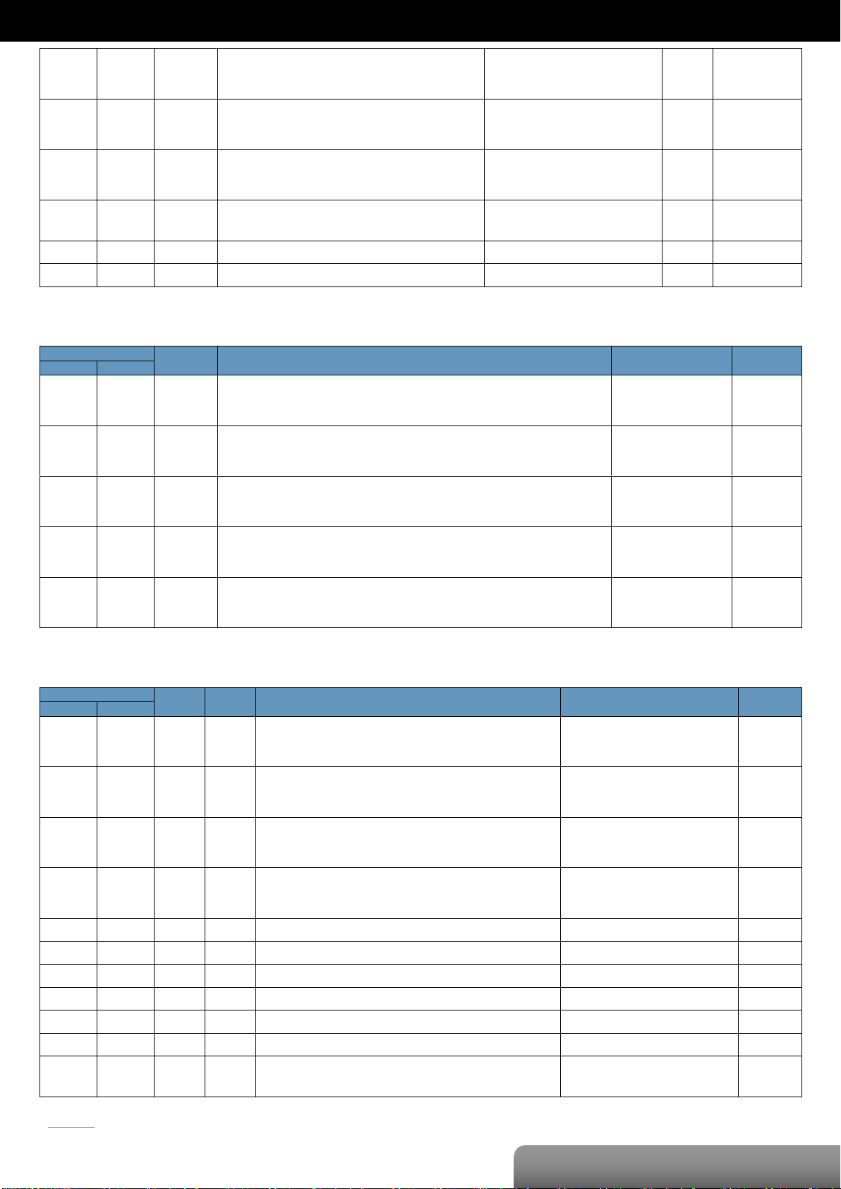
P. 6
| OME-ET-7000/OME-PET-7000 Series
OME-ET-7002/OME-PET-7002
00732
:
00734
02DC
:
02DE
3
Set the AI low alarm mode
0: Momentary mode
1: Latching mode
R/W/E
0
00764
:
00766
02FC
:
02FE
3
Clear the AI high alarm status
1: Clear W -
00796
:
00798
031C
:
031E
3
Clear the AI low alarm status
1: Clear W -
00830
033E
1
Enable/Disable the AI calibration
0: Disable
1: Enable
R/W
-
00831
033F
1
Zero calibration for the channel 0
1: Set W -
00832
0340
1
Span calibration for the channel 0
1: Set W -
Register
Points
Description
Data Format
Attribute
DEC
HEX
10000
:
10005
0000
:
0005
6
DI value
0: Off
1: On
R
10032
:
10037
0020
:
0025
6
Read DI “high latch” status
0: Normal
1: Latched
R
10064
:
10069
0040
:
0045
6
Read DI “low latch” status
0: Normal
1: Latched
R
10224
:
10226
00E0
:
00E2
3
Read AI high alarm status.
When the AI value is higher than the high alarm value, the status becomes 1.
0: Normal
1: Alarmed
R
10256
:
10258
0100
:
0102
3
Read AI low alarm status.
When the AI value is lower than the high alarm value, the status becomes 1.
0: Normal
1: Alarmed
R
Register
Points
No. Per
Point
Description
Data Format
Attribute
DEC
HEX
30000
:
30002
0000
:
0002
3 1 AI value
-32768 to 32767
(0x0000 to 0xFFFF)
R
30032
:
30043
0020
:
002B
6 2 DI counter value
0 to 4294967295
R
30236
:
30238
00EC
:
00EE
3 1 AI historical max. value
-32768 to 32767
(0x0000 to 0xFFFF)
R
30268
:
30270
010C
:
010E
3 1 AI historical min. value
-32768 to 32767
(0x0000 to 0xFFFF)
R
30300
012C 1 1
Number of the DI channel
6
R
30310
0136 1 1
Number of the DO channel
3
R
30320
0140 1 1
Number of the AI channel
3 R 30350
015E 1 1
OS image version
0x123 means version 1.2.3
R
30351
015F 1 1
Firmware version
0x123 means version 1.2.3
R
30353
0161 1 1
I/O version
0x123 means version 1.2.3
R
30360
0168 1 1
Communication state of the pair-connection
0: Normal
<0: Failed
R
Discrete Inputs (1xxxx)
Input Register (3xxxx)
Page 10

P. 7
| OME-ET-7000/OME-PET-7000 Series
OME-ET-7002/OME-PET-7002
Register
Points
No. Per
Point
Description
Data Format
Attribute
Factory Value
DEC
HEX
40200
:
40211
00C8
:
00D3
6
2
Set a preset value for the DI Counter
Any values updated based on the Modbus
communication will not take immediate effect
and not be saved to EEPROM until the register
(00630) is changed by a write operation.
0 to 4294967295
R/W
0
40271
010F 1 1
Set the module identification (Modbus NetID)
1 to 255
R/W/E
1
40296
:
40298
0128
:
012A
3 1 Set the AI high alarm value
-32768 to 32767
(0x0000 to 0xFFFF)
R/W/E
32767
(0x7FFF)
40328
:
40330
0148
:
014A
3 1 Set the AI low alarm value
-32768 to 32767
(0x0000 to 0xFFFF)
R/W/E
-32768
(0x8000)
40427
:
40429
01AB
:
01AD
3 1 Set the AI range
0x07: 4~20 mA
0x08: +/-10 V
0x09: +/-5 V
0x0A: +/-1 V
0x0B: +/-500 mV
0x0C: +/-150 mV
0x0D: +/-20 mA
0x1A: 0~20 mA
R/W/E
0x08
40555
022B 1 1
Read the module reset status
1: Power-on
2: Module Watchdog
3: Software Reset Command
R
-
40556
022C 1 1
Read the boot count of the module
The factory default value is 0 when the
settings are set to the factory default values.
1 to 32767 R -
40557
022D 1 1
Set the Host WDT timeout (unit: second)
0: Disable the Host WDT
5 to 65535: Enable the Host WDT
R/W/E
0
40558
022E 1 1
Read the WDT event count
The initial value is 0 when the module is reset,
and is increased when the WDT even happens.
0 to 32767 R -
40559
022F 1 1
Read the module name
0x7002 R -
Holding Register (4xxxx)
Page 11
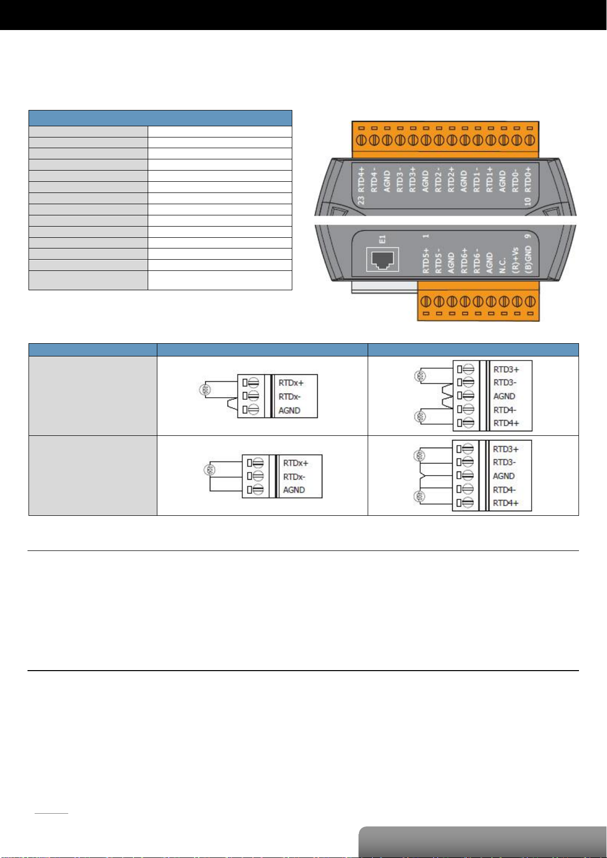
P. 8
OME-ET-7015/OME-PET-7015
| OME-ET-7000/OME-PET-7000 Series
RTD Input
Input Channels
7 (Differential)
Sensor Type
Pt100, Pt1000, Ni120, Cu100, Cu1000
Wire Connection
2/3 wire
Individual Channel Configuration
Yes
Resolution
16-bit
Sampling Rate
12 Samples/Sec. (Total)
Accuracy
+/-0.05%
Zero Drift
+/-0.5 μV/°C
Span Drift
+/-20 μV/°C
Common Mode Rejection
150 dB
Normal Mode Rejection
100 dB
Input Impedance
>1 MΩ
Open Wire Detection
Yes
3-wire RTD Lead Resistance
Elimination
Yes
RTD Input
CH0 1, 2, 5 and 6
CH3 and CH4
2-wire of RTD
3-wire of RTD
OME-ET-7015/OME-PET-7015
I/O Specifications
Wire Connections
Pin Assignments
Tips & Warnings
Use 26-12 AWG wire for signal connections
Strip the wire to a length of 7±0.5mm
Use a crimp terminal for wiring
Avoid high-voltage cables and power equipment as much as possible
Use shielded wire and connect the shielding to the Ax terminal of the channel
Page 12
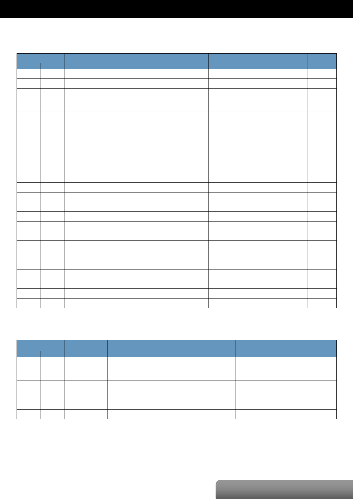
P. 9
| OME-ET-7000/OME-PET-7000 Series
OME-ET-7015/OME-PET-7015
Register
Points
Description
Data Format
Attribute
Factory Value
DEC
HEX
00226
00E2
1
Reset the I/O settings to the factory default state
1: Reset W -
00233
00E9
1
Reboot the module
1: Reboot W -
00595
:
00601
0253
:
0259
7
Enable/Disable the AI function
0: Disable
1: Enable
R/W/E
1
00629
0275
1
Set the AI noise filter
0: Frequency 60 Hz
1: Frequency: 50 Hz
R/W/E
0
00631
0277
1
Set the AI data format
0: Hexadecimal format
1: Engineering unit
R/W/E
0
00632
0278
1
Reset the AI calibration to the factory settings
1: Reset W -
00830
033E
1
Enable/Disable the AI calibration
0: Disable
1: Enable
R/W
-
00831
033F
1
Zero calibration for the channel 0
1: Set W -
00832
0340
1
Span calibration for the channel 0
1: Set W -
00833
0341
1
Zero calibration for the channel 1
1: Set W -
00834
0342
1
Span calibration for the channel 1
1: Set W -
00835
0343
1
Zero calibration for the channel 2
1: Set W -
00836
0344
1
Span calibration for the channel 2
1: Set W -
00837
0345
1
Zero calibration for the channel 3
1: Set W -
00838
0346
1
Span calibration for the channel 3
1: Set W -
00839
0347
1
Zero calibration for the channel 4
1: Set W -
00840
0348
1
Span calibration for the channel 4
1: Set W -
00841
0349
1
Zero calibration for the channel 5
1: Set W -
00842
034A
1
Span calibration for the channel 5
1: Set W -
00843
034B
1
Zero calibration for the channel 6
1: Set W -
00844
034C
1
Span calibration for the channel 6
1: Set W -
Register
Points
No. Per
Point
Description
Data Format
Attribute
DEC
HEX
30000
:
30006
0000
:
0006
7 1 AI value
-32768 to 32767
(0x0000 to 0xFFFF)
R
30320
0140 1 1
Number of the AI channel
7 R 30350
015E 1 1
OS image version
0x123 means version 1.2.3
R
30351
015F 1 1
Firmware version
0x123 means version 1.2.3
R
30353
0161 1 1
I/O version
0x123 means version 1.2.3
R
Modbus Register Table
Coils (0xxxx)
Input Register (3xxxx)
Page 13

P. 10
| OME-ET-7000/OME-PET-7000 Series
OME-ET-7015/OME-PET-7015
Register
Points
No. Per
Point
Description
Data Format
Attribute
Factory Value
DEC
HEX
40110
:
40116
006E
:
0074
7 1 Set the AI temperature offset value
-128 to 127
R/W/E
0
40142
:
40148
008E
:
0094
7 1 Set the AI resistance offset value
0 to 255
R/W/E
0
40271
010F 1 1
Set the module identification
(Modbus NetID)
1 to 255
R/W/E
1
40427
:
40433
01AB
:
01B1
7 1 Set the AI range
0x20: Platinum 100, α=0.00385, -100°C ~ 100°C
0x21: Platinum 100, α=0.00385, 0°C ~ 100°C
0x22: Platinum 100, α=0.00385, 0°C ~ 200°C
0x23: Platinum 100, α=0.00385, 0°C ~ 600°C
0x24: Platinum 100, α=0.003916, -100°C ~ 100°C
0x25: Platinum 100, α=0. 003916, 0°C ~ 100°C
0x26: Platinum 100, α=0. 003916, 0°C ~ 200°C
0x27: Platinum 100, α=0. 003916, 0°C ~ 600°C
0x28: Nickel 120, -80°C ~ 100°C
0x29: Nickel 120, 0°C ~ 100°C
0x2A: Platinum 1000, α=0. 00385, -200°C ~ 600°C
0x2B: Cu 100 @ 0°C, α=0. 00421, -20°C ~ 150°C
0x2C: Cu 100 @ 25°C, α=0. 00427, 0°C ~ 200°C
0x2D: Cu 1000 @ 0°C, α=0. 00421, -20°C ~ 150°C
0x2E: Platinum 100, α=0. 00385, -200°C ~ 200°C
0x2F: Platinum 100, α=0. 003916, -200°C ~ 200°C
0x80: Platinum 100, α=0. 00385, -200°C ~ 600°C
0x81: Platinum 100, α=0. 003916, -200°C ~ 600°C
0x82: Cu 50 @ 0°C, -50°C ~ 150°C
0x83: Nickel 100, -60°C ~ 180°C
R/W/E
0x20
40555
022B 1 1
Read the module reset status
1: Power-on
2: Module Watchdog
3: Software Reset Command
R
-
40556
022C 1 1
Read the boot count of the module
The factory default value is 0 when
the settings are set to the factory
default values.
1 to 32767 R -
40557
022D 1 1
Set the Host WDT timeout
(unit: second)
0: Disable the Host WDT
5 to 65535: Enable the Host WDT
R/W/E
0
40558
022E 1 1
Read the WDT event count
The initial value is 0 when the
module is reset, and is increased
when the WDT even happens.
0 to 32767 R -
40559
022F 1 1
Read the module name
0x7015 R -
Holding Register (4xxxx)
Page 14
P. 11
OME-ET-7017/OME-PET-7017
| OME-ET-7000/OME-PET-7000 Series
Analog Input
Input Channels
8 (Differential)
Input Type
+/-150 mV, +/-500 mV, +/-1 V, +/-5 V, +/-10 V,
0~20 mA, +/-20 mA, 4~20 mA
(jumper selectable)
Individual Channel Configuration
Yes
Resolution
Normal Mode
16-bit
Fast Mode
12-bit
Sampling Rate
Normal Mode
10 Samples/Sec. (Total)
Fast Mode
60 Samples/Sec. (Total)
Accuracy
Normal Mode
+/-0.1%
Fast Mode
+/-0.5% or better
Zero Drift
+/-20 uV/°C
Span Drift
+/-25 ppm/°C
Overvoltage Protection
240 Vrms
Input Impedance
Voltage
2 MΩ
Current
125 Ω
Common Mode Rejection
86 dB Min.
Normal Mode Rejection
100 dB
Digital Output
Output Channels
4
Type
Isolated Open Collector (Sink)
Max. Load Current
700 mA/Channel
Load Voltage
5 VDC~50 VDC
Overvoltage Protection
60 VDC
Overload Protection
1.4 A
Short-circuit Protection
Yes
Power-on Value
Yes, Programmable
Safe Value
Yes, Programmable
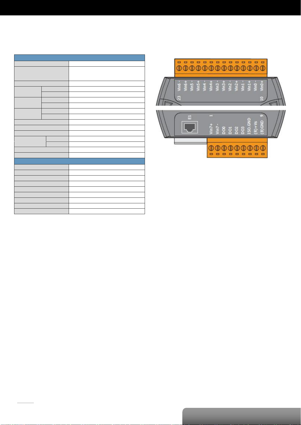
OME-ET-7017/OME-PET-7017
I/O Specifications
Pin Assignments
Page 15
P. 12
OME-ET-7017/OME-PET-7017
| OME-ET-7000/OME-PET-7000 Series
Voltage Input
Current Input
Digital Output
ON State
Readback as 1
OFF State
Readback as 0
Open Collector (Sink)
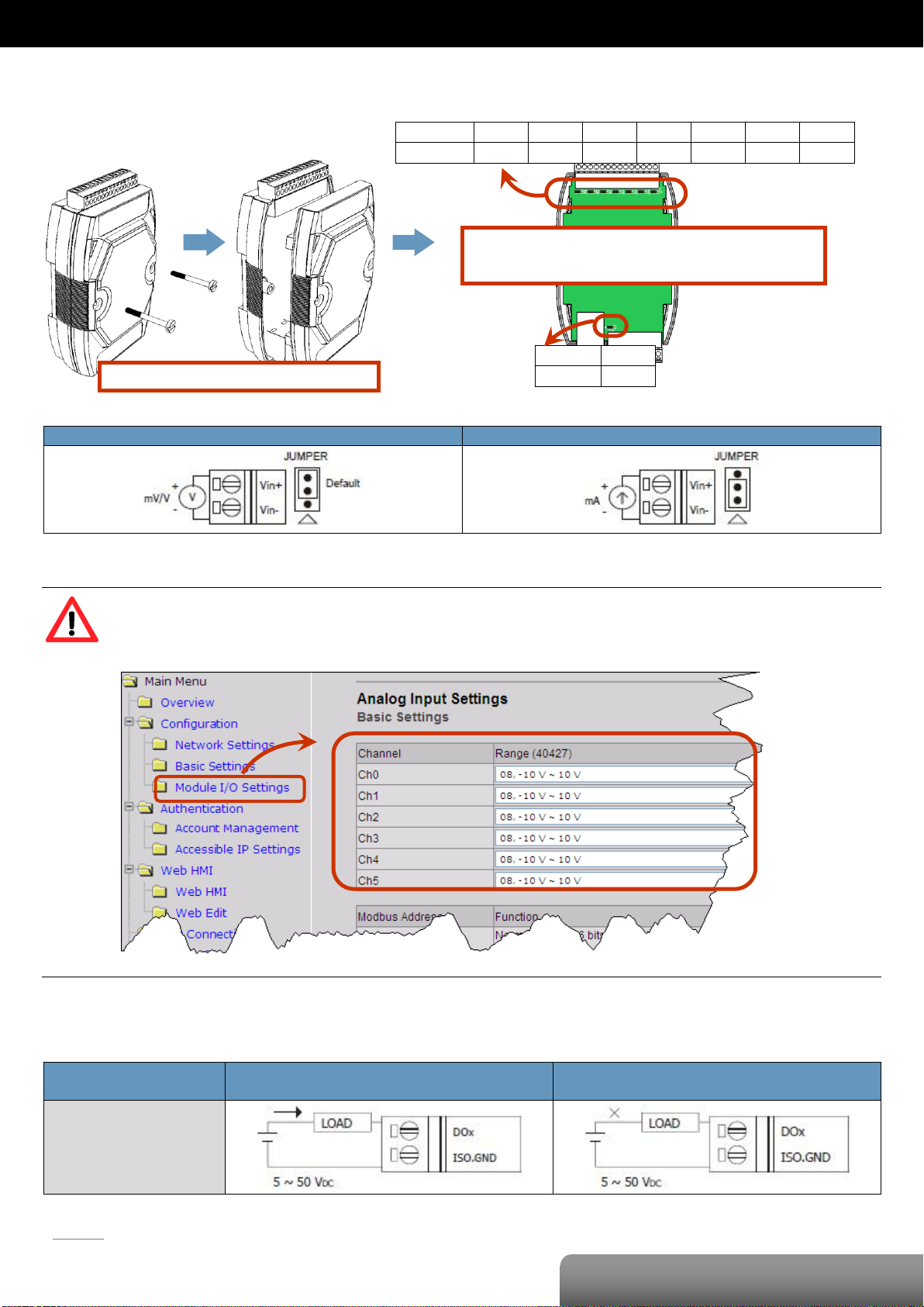
Remove the top case of the module.
The selection jumpers are next to the connector.
Refer to the table below to set the input type.
Channel
Vin6 ±
Vin5 ±
Vin4 ±
Vin3 ±
Vin2 ±
Vin1 ±
Vin0 ±
Jumper
J7
J6
J5
J4
J3
J2
J1
Channel
Vin7 ±
Jumper
J8
Voltage/Current Input Selection Jumper Settings
Tips & Warnings
The jumper settings of the input type for each AI channel must correspond to the input range for each AI
channel of the web interface.
Wire Connections
Page 16
P. 13
OME-ET-7017/OME-PET-7017
| OME-ET-7000/OME-PET-7000 Series
Register
Points
Description
Data Format
Attribute
Factory Value
DEC
HEX
00000
:
00003
0000
:
0003
4
DO value
0: Off
1: On
R/W
-
00162
:
00169
00A2
:
00A9
8
Clear 1-ch historical AI max. value
1: Clear W -
00194
:
00201
00C2
:
00C9
8
Clear 1-ch historical AI min. value
1: Clear W -
00226
00E2
1
Reset the I/O settings to the factory default state
1: Reset W -
00233
00E9
1
Reboot the module
1: Reboot W -
00431
01AF
1
Save the DO power-on value to the EEPROM
1: Save
W/E
-
00432
01B0
1
Save the DO safe value to the EEPROM
1: Save
W/E
-
00435
:
00438
01B3
:
01B6
4
Enable/Disable the DO power-on value function
0: Disable
1: Enable
R/W
0
00515
:
00518
0203
:
0206
4
Enable/Disable the DO safe value function
0: Disable
1: Enable
R/W
0
00595
:
00602
0253
:
025A
8
Enable/Disable the AI function
0: Disable
1: Enable
R/W/E
1
00628
0274
1
Set the AI sampling rate
0: Normal mode (10 Hz, 16 bits)
1: Fast mode (60 Hz, 12 bits)
R/W/E
0
00629
0275
1
Set the AI noise filter
0: Frequency 60 Hz
1: Frequency: 50 Hz
R/W/E
0
00631
0277
1
Set the AI data format
0: Hexadecimal format
1: Engineering unit
R/W/E
0
00632
0278
1
Reset the AI calibration to the factory settings
1: Reset W -
00634
027A
1
Clear all historical AI max. values
1: Clear W -
00635
027B
1
Clear all historical AI min. values
1: Clear W -
00636
:
00643
027C
:
0283
8
Enable/Disable the AI high alarm function
0: Disable
1: Enable
R/W/E
0
00668
:
00675
029C
:
02A3
8
Enable/Disable the AI low alarm function
0: Disable
1: Enable
R/W/E
0
00700
:
00707
02BC
:
02C3
8
Set the AI high alarm mode
0: Momentary mode
1: Latching mode
R/W/E
0
00732
:
00739
02DC
:
02E3
8
Set the AI low alarm mode
0: Momentary mode
1: Latching mode
R/W/E
0
00764
:
00771
02FC
:
0303
8
Clear the AI high alarm status
1: Clear W -
00796
:
00803
031C
:
0323
8
Clear the AI low alarm status
1: Clear W -
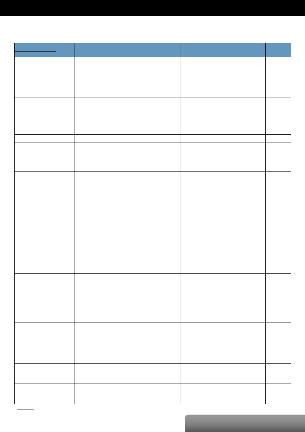
Modbus Register Table
Coils (0xxxx)
Page 17
P. 14
OME-ET-7017/OME-PET-7017
| OME-ET-7000/OME-PET-7000 Series
00830
033E
1
Enable/Disable the AI calibration
0: Disable
1: Enable
R/W
-
00831
033F
1
Zero calibration for the channel 0
1: Set W -
00832
0340
1
Span calibration for the channel 0
1: Set W -
Register
Points
Description
Data Format
Attribute
DEC
HEX
10224
:
10231
00E0
:
00E7
8
Read AI high alarm status.
When the AI value is higher than the high alarm value, the status becomes 1.
0: Normal
1: Alarmed
R
10256
:
10263
0100
:
0107
8
Read AI low alarm status.
When the AI value is lower than the high alarm value, the status becomes 1.
0: Normal
1: Alarmed
R
Register
Points
No. Per
Point
Description
Data Format
Attribute
DEC
HEX
30000
:
30007
0000
:
0007
8 1 AI value
-32768 to 32767
(0x0000 to 0xFFFF)
R
30236
:
30243
00EC
:
00F3
8 1 AI historical max. value
-32768 to 32767
(0x0000 to 0xFFFF)
R
30268
:
30275
010C
:
0113
8 1 AI historical min. value
-32768 to 32767
(0x0000 to 0xFFFF)
R
30310
0136 1 1
Number of the DO channel
4
R
30320
0140 1 1
Number of the AI channel
8
R
30350
015E 1 1
OS image version
0x123 means version 1.2.3
R
30351
015F 1 1
Firmware version
0x123 means version 1.2.3
R
30353
0161 1 1
I/O version
0x123 means version 1.2.3
R
30360
0168 1 1
Communication state of the pair-connection
0: Normal
<0: Failed
R
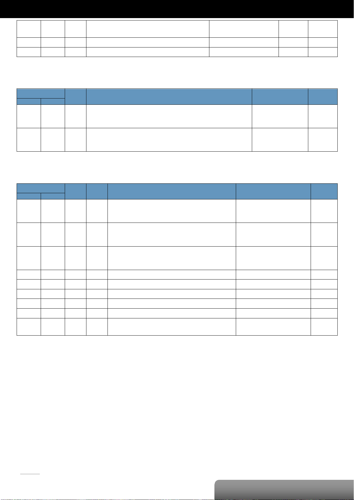
Discrete Inputs (1xxxx)
Input Register (3xxxx)
Page 18

P. 15
OME-ET-7017/OME-PET-7017
| OME-ET-7000/OME-PET-7000 Series
Register
Points
No. Per
Point
Description
Data Format
Attribute
Factory Value
DEC
HEX
40271
010F 1 1
Set the module identification (Modbus NetID)
1 to 255
R/W/E
1
40296
:
40303
0128
:
012F
8 1 Set the AI high alarm value
-32768 to 32767
(0x0000 to 0xFFFF)
R/W/E
32767
(0x7FFF)
40328
:
40335
0148
:
014F
8 1 Set the AI low alarm value
-32768 to 32767
(0x0000 to 0xFFFF)
R/W/E
-32768
(0x8000)
40427
:
40434
01AB
:
01B2
8 1 Set the AI range
0x07: 4 ~ 20 mA
0x08: +/-10 V
0x09: +/-5 V
0x0A: +/-1 V
0x0B: +/-500 mV
0x0C: +/-150 mV
0x0D: +/-20 mA
0x1A: 0~20 mA
R/W/E
0x08
40555
022B 1 1
Read the module reset status
1: Power-on
2: Module Watchdog
3: Software Reset Command
R
-
40556
022C 1 1
Read the boot count of the module
The factory default value is 0 when the settings
are set to the factory default values.
1 to 32767 R -
40557
022D 1 1
Set the Host WDT timeout (unit: second)
0: Disable the Host WDT
5 to 65535: Enable the Host WDT
R/W/E
0
40558
022E 1 1
Read the WDT event count
The initial value is 0 when the module is reset,
and is increased when the WDT even happens.
0 to 32767 R -
40559
022F 1 1
Read the module name
0x7017 R -
Holding Register (4xxxx)
Page 19
P. 16
OME-ET-7017-10/OME-PET-7017-10
| OME-ET-7000/OME-PET-7000 Series
Analog Input
Input Channels
10 differential or 20 single-ended (Note)
(software selectable)
Input Type
+/-150 mV, +/-500 mV, +/-1 V, +/-5 V, +/-10 V,
0~20 mA, +/-20 mA, 4~20 mA
(jumper selectable)
Individual Channel Configuration
Yes
Resolution
Normal Mode
16-bit
Fast Mode
12-bit
Sampling Rate
Normal Mode
10 Samples/Sec. (Total)
Fast Mode
60 Samples/Sec. (Total)
Accuracy
Normal Mode
+/-0.1%
Fast Mode
+/-0.5% or better
Zero Drift
+/-20 uV/°C
Span Drift
+/-25 ppm/°C
Overvoltage
Protection
Differential
240 Vrms
Single-ended
150 Vrms
Input
Impedance
Voltage
2 MΩ (Differential), 1 MΩ (Single-ended)
Current
125 Ω
Common Mode Rejection
86 dB Min.
Normal Mode Rejection
100 dB
Note: Differential mode can be used for voltage input and current input.
Single-ended mode can be used for voltage input only
OME-ET-7017-10/OME-PET-7017-10
I/O Specifications
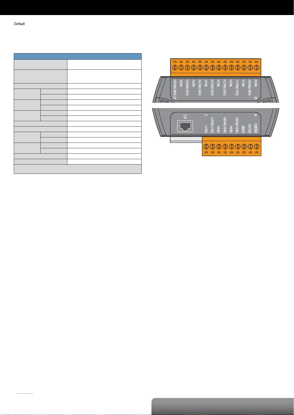
Pin Assignments
Page 20
P. 17
OME-ET-7017-10/OME-PET-7017-10
| OME-ET-7000/OME-PET-7000 Series
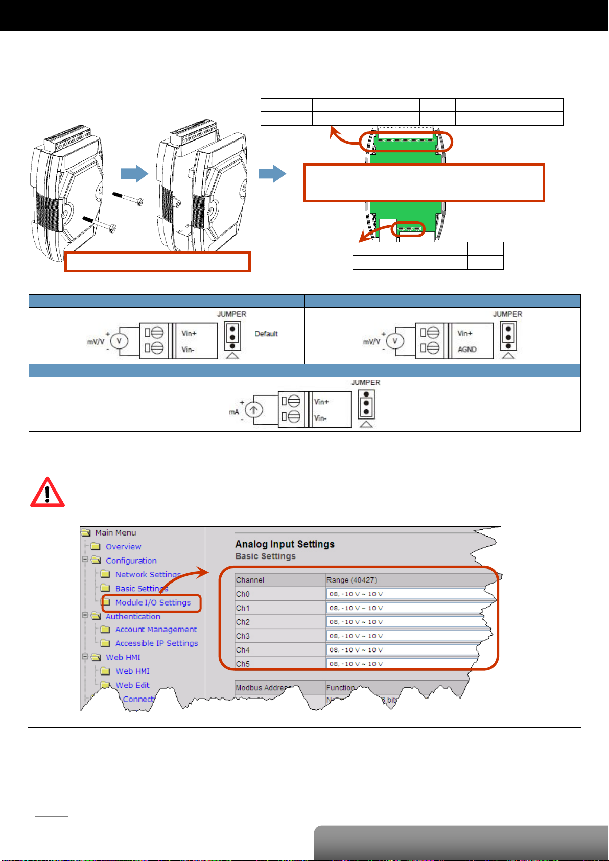
Voltage Input (Differential Mode)
Voltage Input (Single-ended Mode)
Current Input
Remove the top case of the module.
The selection jumpers are next to the connector.
Refer to the table below to set the input type.
Channel
Vin6 ±
Vin5 ±
Vin4 ±
Vin3 ±
Vin2 ±
Vin1 ±
Vin0 ±
Jumper
J7
J6
J5
J4
J3
J2
J1
Channel
Vin7 ±
Vin8 ±
Vin9 ±
Jumper
J8
J9
J10
Voltage/Current Input Selection Jumper Settings
Tips & Warnings
The jumper settings of the input type for each AI channel must correspond to the input range for each AI
channel of the web interface.
Page 21
P. 18
OME-ET-7017-10/OME-PET-7017-10
| OME-ET-7000/OME-PET-7000 Series
Register
Points
Description
Data Format
Attribute
Factory Value
DEC
HEX
00162
:
00181
00A2
:
00B5
20
Clear 1-ch historical AI max. value
1: Clear W -
00194
:
00213
00C2
:
00D5
20
Clear 1-ch historical AI min. value
1: Clear W -
00226
00E2
1
Reset the I/O settings to the factory default state
1: Reset W -
00233
00E9
1
Reboot the module
1: Reboot W -
00595
:
00614
0253
:
0266
20
Enable/Disable the AI function
0: Disable
1: Enable
R/W/E
1
00628
0274
1
Set the AI sampling rate
0: Normal mode (10 Hz, 16 bits)
1: Fast mode (60 Hz, 12 bits)
R/W/E
0
00629
0275
1
Set the AI noise filter
0: Frequency 60 Hz
1: Frequency 50 Hz
R/W/E
0
00631
0277
1
Set the AI data format
0: Hexadecimal format
1: Engineering unit
R/W/E
0
00632
0278
1
Reset the AI calibration to the factory settings
1: Reset W -
00634
027A
1
Clear all historical AI max. values
1: Clear W -
00635
027B
1
Clear all historical AI min. values
1: Clear W -
00636
:
00655
027C
:
028F
20
Enable/Disable the AI high alarm function
0: Disable
1: Enable
R/W/E
0
00668
:
00687
029C
:
02AF
20
Enable/Disable the AI low alarm function
0: Disable
1: Enable
R/W/E
0
00700
:
00719
02BC
:
02CF
20
Set the AI high alarm mode
0: Momentary mode
1: Latching mode
R/W/E
0
00732
:
00751
02DC
:
02EF
20
Set the AI low alarm mode
0: Momentary mode
1: Latching mode
R/W/E
0
00764
:
00783
02FC
:
030F
20
Clear the AI high alarm status
1: Clear W -
00796
:
00815
031C
:
032F
20
Clear the AI low alarm status
1: Clear W -
00830
033E
1
Enable/Disable the AI calibration
0: Disable
1: Enable
R/W
-
00831
033F
1
Zero calibration for the channel 0
1: Set W -
00832
0340
1
Span calibration for the channel 0
1: Set W -
00833
0341
1
Set the AI mode
0: Differential
1: Single-ended
R/W/E
0
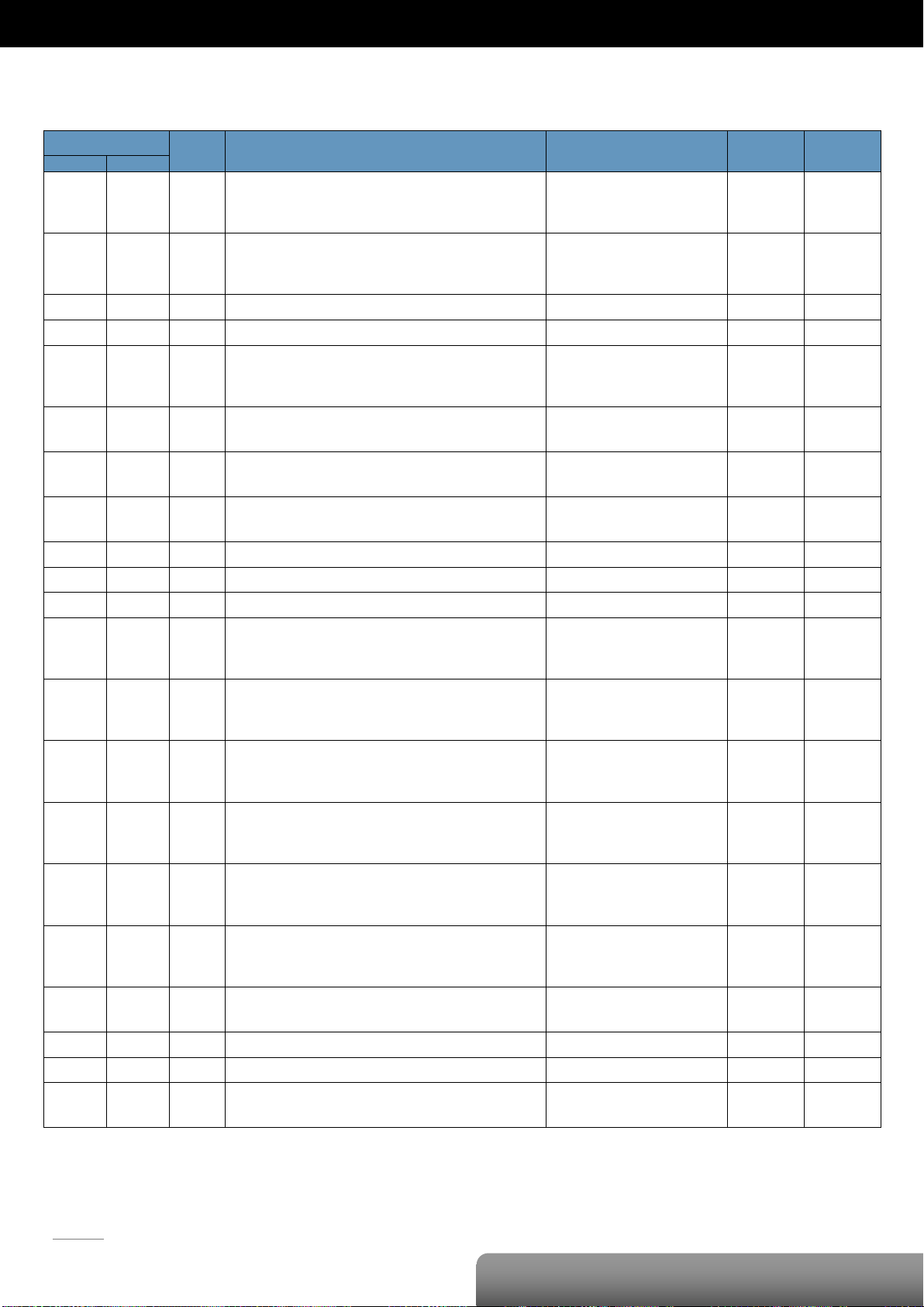
Modbus Register Table
Coils (0xxxx)
Page 22
P. 19
OME-ET-7017-10/OME-PET-7017-10
| OME-ET-7000/OME-PET-7000 Series
Register
Points
Description
Data Format
Attribute
DEC
HEX
10224
:
10243
00E0
:
00F3
20
Read AI high alarm status.
When the AI value is higher than the high alarm value, the status becomes 1.
0: Normal
1: Alarmed
R
10256
:
10275
0100
:
0113
20
Read AI low alarm status.
When the AI value is lower than the high alarm value, the status becomes 1.
0: Normal
1: Alarmed
R
Register
Points
No. Per
Point
Description
Data Format
Attribute
DEC
HEX
30000
:
30019
0000
:
0013
20 1 AI value
-32768 to 32767
(0x0000 to 0xFFFF)
R
30236
:
30255
00EC
:
00FF
20 1 AI historical max. value
-32768 to 32767
(0x0000 to 0xFFFF)
R
30268
:
30287
010C
:
011F
20 1 AI historical min. value
-32768 to 32767
(0x0000 to 0xFFFF)
R
30320
0140 1 1
Number of the AI channel
10/20
R
30350
015E 1 1
OS image version
0x123 means version 1.2.3
R
30351
015F 1 1
Firmware version
0x123 means version 1.2.3
R
30353
0161 1 1
I/O version
0x123 means version 1.2.3
R
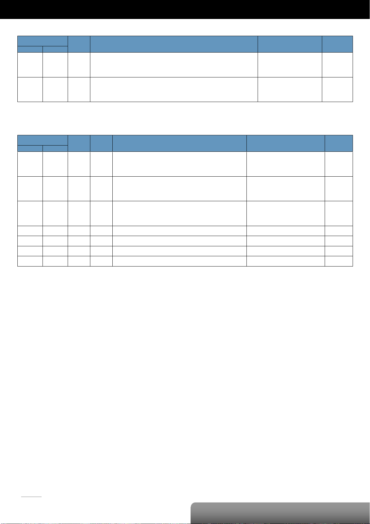
Discrete Inputs (1xxxx)
Input Register (3xxxx)
Page 23

P. 20
OME-ET-7017-10/OME-PET-7017-10
| OME-ET-7000/OME-PET-7000 Series
Register
Points
No. Per
Point
Description
Data Format
Attribute
Factory Value
DEC
HEX
40271
010F 1 1
Set the module identification (Modbus NetID)
1 to 255
R/W/E
1
40296
:
40315
0128
:
013B
20 1 Set the AI high alarm value
-32768 to 32767
(0x0000 to 0xFFFF)
R/W/E
32767
(0x7FFF)
40328
:
40347
0148
:
015B
20 1 Set the AI low alarm value
-32768 to 32767
(0x0000 to 0xFFFF)
R/W/E
-32768
(0x8000)
40427
:
40446
01AB
:
01BF
20 1 Set the AI range
0x07: 4 ~ 20 mA
0x08: +/-10 V
0x09: +/-5 V
0x0A: +/-1 V
0x0B: +/-500 mV
0x0C: +/-150 mV
0x0D: +/-20 mA
0x1A: 0~20 mA
R/W/E
0x08
40555
022B 1 1
Read the module reset status
1: Power-on
2: Module Watchdog
3: Software Reset Command
R
-
40556
022C 1 1
Read the boot count of the module
The factory default value is 0 when the
settings are set to the factory default values.
1 to 32767 R -
40557
022D 1 1
Set the Host WDT timeout (unit: second)
0: Disable the Host WDT
5 to 65535: Enable the Host WDT
R/W/E
0
40558
022E 1 1
Read the WDT event count
The initial value is 0 when the module is reset,
and is increased when the WDT even happens.
0 to 32767 R -
40559
022F 1 1
Read the module name
0x7017 R -
Holding Register (4xxxx)
Page 24
P. 21
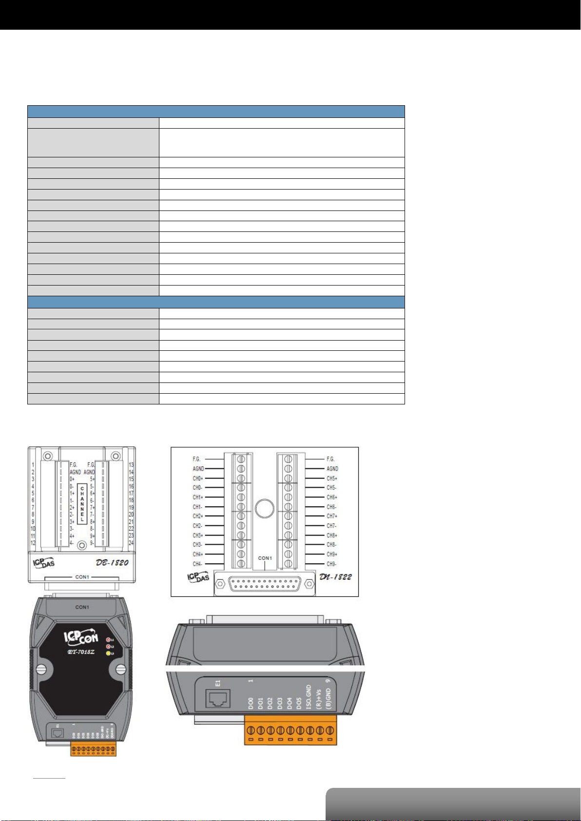
OME-ET-7018Z/OME-PET-7018Z
| OME-ET-7000/OME-PET-7000 Series
Analog Input
Input Channels
10 (Differential)
Input Type
+/-15 mV, +/-50 mV, +/-100 mV, +/-500 mV, +/-1 V, +/-2.5V
0~20 mA, +/-20 mA, 4~20 mA (Requires Optional External 125Ω Resistor)
Thermocouple (J, K, T, E, R, S, B, N, C, L, M and LDIN43710)
Individual Channel Configuration
Yes
Resolution
16-bit
Sampling Rate
10 Samples/Sec. (Total)
Accuracy
+/-0.1% or better
Zero Drift
+/-0.5 uV/°C
Span Drift
+/-25 ppm/°C
Overvoltage Protection
240 Vrms
Input Impedance
>300 KΩ
Common Mode Rejection
150 dB Min.
Normal Mode Rejection
100 dB
Temperature Outputs Consistency
Yes
Stable Temperature Output In The Field
Yes
Open Wire Detection
Yes
Digital Output
Output Channels
6
Type
Isolated Open Collector (Sink)
Max. Load Current
700 mA/Channel
Load Voltage
5 VDC~50 VDC
Overvoltage Protection
60 VDC
Overload Protection
1.4 A
Short-circuit Protection
Yes
Power-on Value
Yes, Programmable
Safe Value
Yes, Programmable
OME-ET-7018Z/OME-PET-7018Z
I/O Specifications
Pin Assignments
Page 25
P. 22
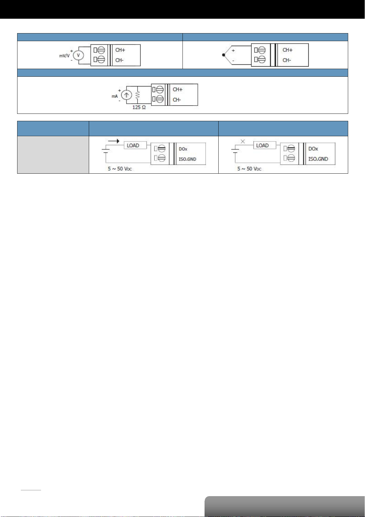
OME-ET-7018Z/OME-PET-7018Z
| OME-ET-7000/OME-PET-7000 Series
Voltage Input
Thermocouple Input
Current Input
Digital Output
ON State
Readback as 1
OFF State
Readback as 0
Open Collector (Sink)
Note that an optional external 125 Ω resistor is
required when connecting to a current source,
Wire Connections
Page 26
P. 23
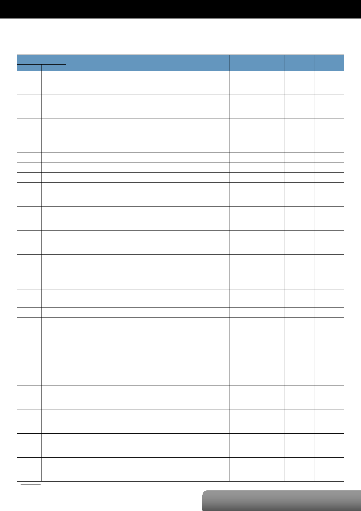
OME-ET-7018Z/OME-PET-7018Z
| OME-ET-7000/OME-PET-7000 Series
Register
Points
Description
Data Format
Attribute
Factory Value
DEC
HEX
00000
:
00005
0000
:
0005
6
DO value
0: Off
1: On
R/W
-
00162
:
00171
00A2
:
00AB
10
Clear 1-ch historical AI max. value
1: Clear W -
00194
:
00203
00C2
:
00CB
10
Clear 1-ch historical AI min. value
1: Clear W -
00226
00E2
1
Reset the I/O settings to the factory default state
1: Reset W -
00233
00E9
1
Reboot the module
1: Reboot W -
00431
01AF
1
Save the DO power-on value to the EEPROM
1: Save
W/E
-
00432
01B0
1
Save the DO safe value to the EEPROM
1: Save
W/E
-
00435
:
00440
01B3
:
01B8
6
Enable/Disable the DO power-on value function
0: Disable
1: Enable
R/W
0
00515
:
00520
0203
:
0208
6
Enable/Disable the DO safe value function
0: Disable
1: Enable
R/W
0
00595
:
00604
0253
:
025C
10
Enable/Disable the AI function
0: Disable
1: Enable
R/W/E
1
00627
0273
1
Enable/Disable the CJC function
0: Disable
1: Enable
R/W/E
1
00629
0275
1
Set the AI noise filter
0: Frequency 60 Hz
1: Frequency 50 Hz
R/W/E
0
00631
0277
1
Set the AI data format
0: Hexadecimal format
1: Engineering unit
R/W/E
0
00632
0278
1
Reset the AI calibration to the factory settings
1: Reset W -
00634
027A
1
Clear all historical AI max. values
1: Clear W -
00635
027B
1
Clear all historical AI min. values
1: Clear W -
00636
:
00645
027C
:
0285
10
Enable/Disable the AI high alarm function
0: Disable
1: Enable
R/W/E
0
00668
:
00677
029C
:
02A5
10
Enable/Disable the AI low alarm function
0: Disable
1: Enable
R/W/E
0
00700
:
00709
02BC
:
02C5
10
Set the AI high alarm mode
0: Momentary mode
1: Latching mode
R/W/E
0
00732
:
00741
02DC
:
02E5
10
Set the AI low alarm mode
0: Momentary mode
1: Latching mode
R/W/E
0
00764
:
00773
02FC
:
0305
10
Clear the AI high alarm status
1: Clear W -
00796
:
00805
031C
:
0325
10
Clear the AI low alarm status
1: Clear W -
Modbus Register Table
Coils (0xxxx)
Page 27
P. 24
OME-ET-7018Z/OME-PET-7018Z
| OME-ET-7000/OME-PET-7000 Series
00830
033E
1
Enable/Disable the AI calibration
0: Disable
1: Enable
R/W
-
00831
033F
1
Zero calibration for the channel 0
1: Set W -
00832
0340
1
Span calibration for the channel 0
1: Set W -
Register
Points
Description
Data Format
Attribute
DEC
HEX
10224
:
10233
00E0
:
00E9
10
Read AI high alarm status.
When the AI value is higher than the high alarm value, the status becomes 1.
0: Normal
1: Alarmed
R
10256
:
10265
0100
:
0109
10
Read AI low alarm status.
When the AI value is lower than the high alarm value, the status becomes 1.
0: Normal
1: Alarmed
R
Register
Points
No. Per
Point
Description
Data Format
Attribute
DEC
HEX
30000
:
30009
0000
:
0009
10 1 AI value
-32768 to 32767
(0x0000 to 0xFFFF)
R
30143
008F
1 1 CJC value
-32768 to 32767
R
30236
:
30245
00EC
:
00F5
10 1 AI historical max. value
-32768 to 32767
(0x0000 to 0xFFFF)
R
30268
:
30277
010C
:
0115
10 1 AI historical min. value
-32768 to 32767
(0x0000 to 0xFFFF)
R
30310
0136 1 1
Number of the DO channel
6
R
30320
0140 1 1
Number of the AI channel
10 R 30350
015E 1 1
OS image version
0x123 means version 1.2.3
R
30351
015F 1 1
Firmware version
0x123 means version 1.2.3
R
30353
0161 1 1
I/O version
0x123 means version 1.2.3
R
30360
0168 1 1
Communication state of the pair-connection
0: Normal
<0: Failed
R
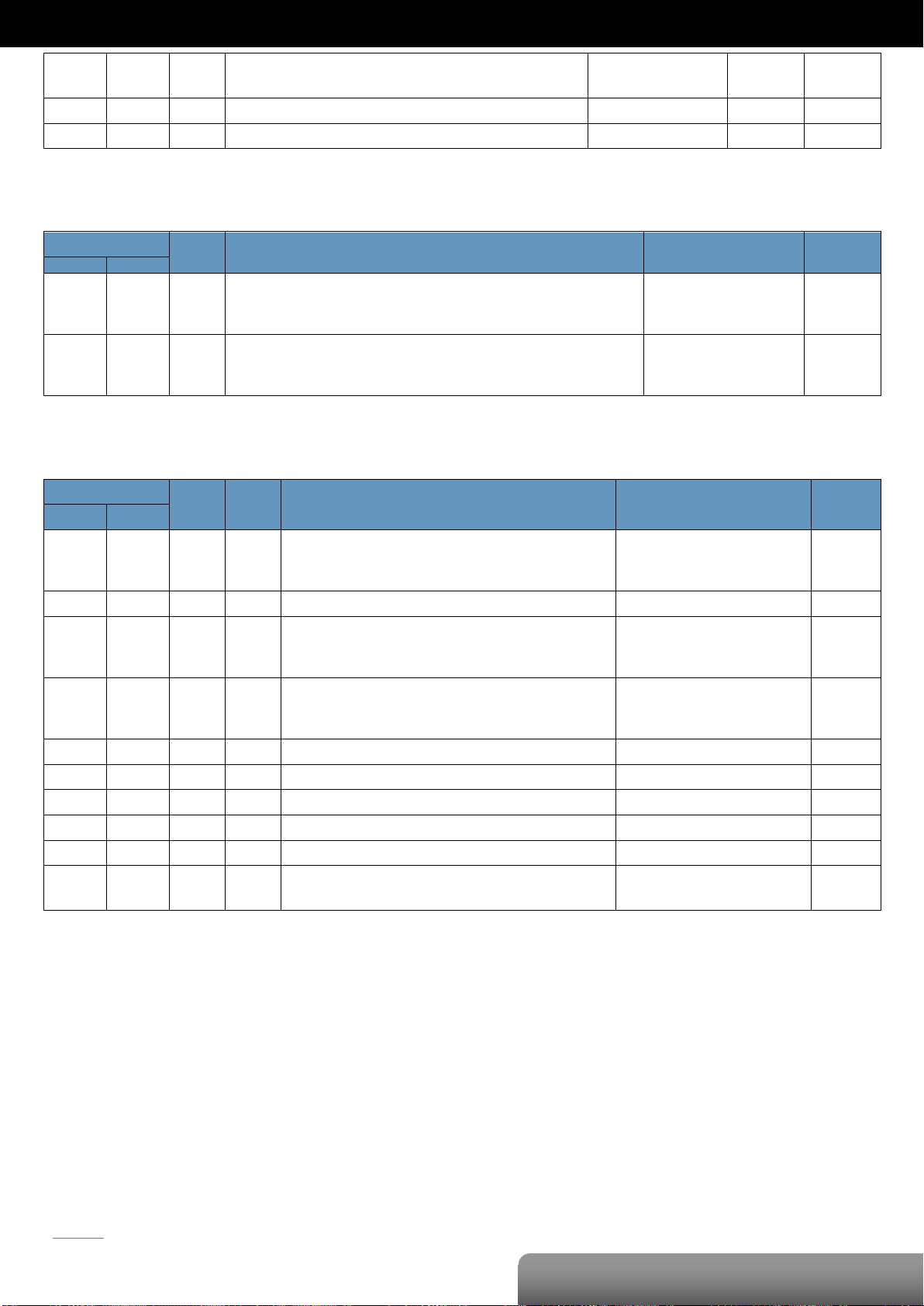
Discrete Inputs (1xxxx)
Input Register (3xxxx)
Page 28
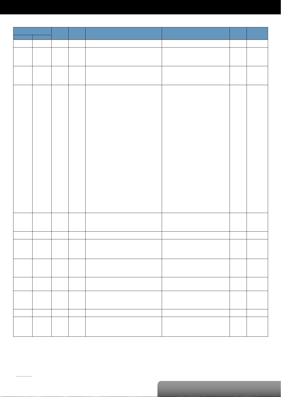
P. 25
OME-ET-7018Z/OME-PET-7018Z
| OME-ET-7000/OME-PET-7000 Series
Register
Points
No. Per
Point
Description
Data Format
Attribute
Factory Value
DEC
HEX
40271
010F 1 1
Set the module identification (Modbus NetID)
1 to 255
R/W/E
1
40296
:
40305
0128
:
0131
10 1 Set the AI high alarm value
-32768 to 32767
(0x0000 to 0xFFFF)
R/W/E
32767
(0x7FFF)
40328
:
40337
0148
:
0151
10 1 Set the AI low alarm value
-32768 to 32767
(0x0000 to 0xFFFF)
R/W/E
-32768
(0x8000)
40427
:
40436
01AB
:
01B4
10 1 Set the AI range
0x00: +/-15 mV
0x01: +/-50 mV
0x02: +/-100 mV
0x03: +/-500 mV
0x04: +/-1 V
0x05: +/-2.5 V
0x06: +/-20 mA
0x07: 4 ~ 20 mA
0x0E: Type J, -210°C ~ 760°C
0x0F: Type K, -270°C ~ 1372°C
0x10: Type T, -270°C ~ 400°C
0x11: Type E, -270°C ~ 1000°C
0x12: Type R, 0°C ~ 1768°C
0x13: Type S, 0°C ~ 1768°C
0x14: Type B, 0°C ~ 1820°C
0x15: Type N, -270°C ~ 1300°C
0x16: Type C, 0°C ~ 2320°C
0x17: Type L, -200°C ~ 800°C
0x18: Type M, -200°C ~ 100°C
0x19: Type L DIN43710, -200°C ~ 900°C
0x1A: 0 ~ 20 mA
R/W/E
0x05
40491
:
40500
01EB
:
01F4
10 1 Set the CJC Offset for the single channel
-9999 to 9999
R/W/E
0
40523
020B 1 1
Set the CJC Offset for all channels
-9999 to 9999
R/W/E
0
40555
022B 1 1
Read the module reset status
1: Power-on
2: Module Watchdog
3: Software Reset Command
R
-
40556
022C 1 1
Read the boot count of the module
The factory default value is 0 when the
settings are set to the factory default values.
1 to 32767
R
-
40557
022D 1 1
Set the Host WDT timeout (unit: second)
0: Disable the Host WDT
5 to 65535: Enable the Host WDT
R/W/E
0
40558
022E 1 1
Read the WDT event count
The initial value is 0 when the module is reset,
and is increased when the WDT even happens.
0 to 32767
R
-
40559
022F 1 1
Read the module name
0x7018 R -
40589
024D 1 1
Set the CJC operation status
0: Stop
1: Start
2: Read once
R/W/E
1
Holding Register (4xxxx)
Page 29
P. 26
| OME-ET-7000/OME-PET-7000 Series
OME-ET-7019/OME-PET-7019
Analog Input
Input Channels
8 (Differential)
Input Type
+/-15 mV, +/-50 mV, +/-100 mV, +/-150 mV,
+/-500 mV, +/-1 V, +/-5 V, +/-10 V, 0~20 mA,
+/-20 mA, 4~20 mA
Thermocouple (J, K, T, E, R, S, B, N, C, L, M
and LDIN43710)
Individual Channel Configuration
Yes
Resolution
16-bit
Sampling Rate
10 Samples/Sec. (Total)
Accuracy
+/-0.1% or better
Zero Drift
+/-10 uV/°C
Span Drift
+/-25 ppm/°C
Overvoltage Protection
240 Vrms
Input Impedance
Voltage
>1 MΩ
Current
125 Ω
Common Mode Rejection
86 dB Min.
Normal Mode Rejection
100 dB
Open Wire Detection
Yes
Digital Output
Output Channels
4
Type
Isolated Open Collector (Sink)
Max. Load Current
700 mA/Channel
Load Voltage
5 VDC~50 VDC
Overvoltage Protection
60 VDC
Overload Protection
1.4 A
Short-circuit Protection
Yes
Power-on Value
Yes, Programmable
Safe Value
Yes, Programmable
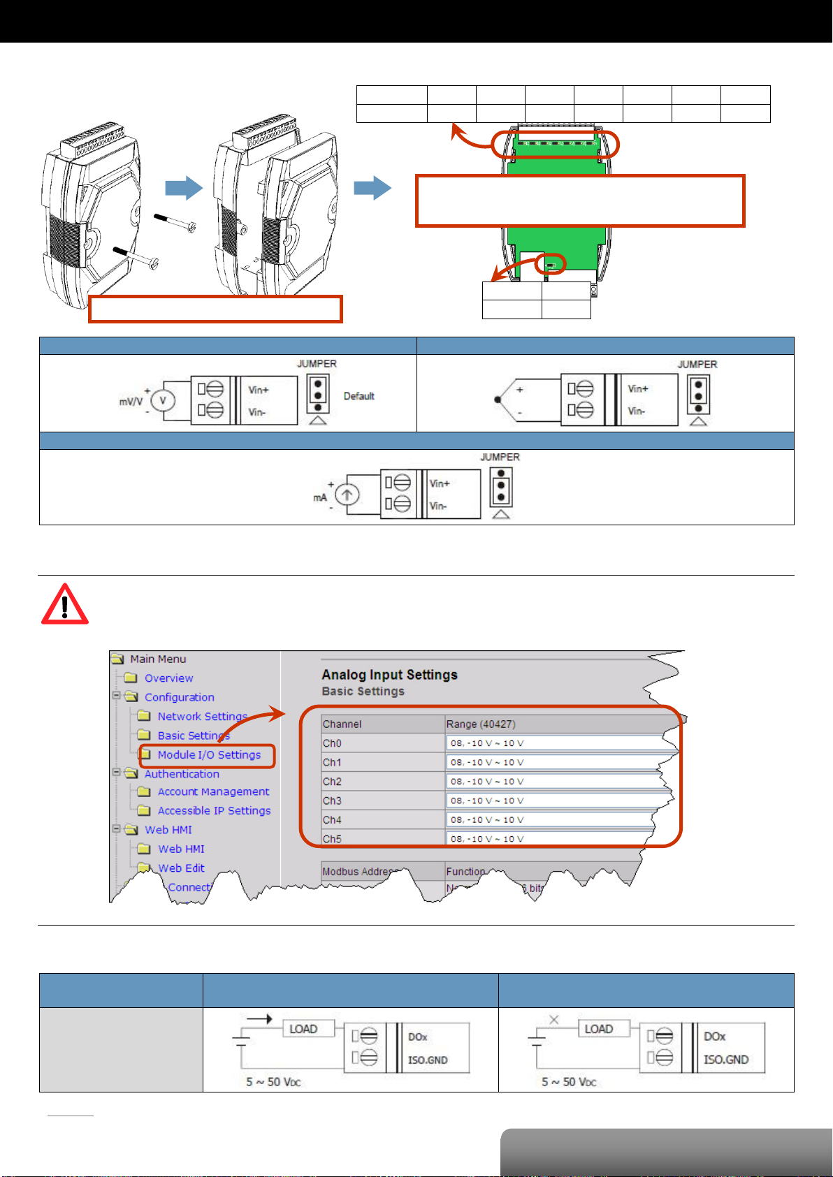
OME-ET-7019/OME-PET-7019
I/O Specifications
Pin Assignments
Page 30
P. 27
| OME-ET-7000/OME-PET-7000 Series
OME-ET-7019/OME-PET-7019
Voltage Input
Thermocouple Input
Current Input
Digital Output
ON State
Readback as 1
OFF State
Readback as 0
Open Collector (Sink)
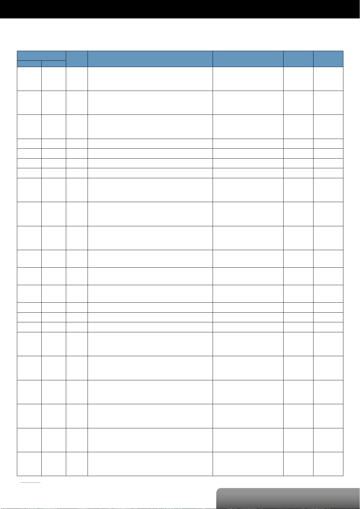
Remove the top case of the module.
The selection jumpers are next to the connector.
Refer to the table below to set the input type.
Channel
Vin6 ±
Vin5 ±
Vin4 ±
Vin3 ±
Vin2 ±
Vin1 ±
Vin0 ±
Jumper
J7
J6
J5
J4
J3
J2
J1
Channel
Vin7 ±
Jumper
J8
Voltage/Current Input Selection Jumper Settings
Tips & Warnings
The jumper settings of the input type for each AI channel must correspond to the input range for each AI
channel of the web interface.
Wire Connections
Page 31
P. 28
| OME-ET-7000/OME-PET-7000 Series
OME-ET-7019/OME-PET-7019
Register
Points
Description
Data Format
Attribute
Factory Value
DEC
HEX
00000
:
00003
0000
:
0003
4
DO value
0: Off
1: On
R/W
-
00162
:
00169
00A2
:
00A9
8
Clear 1-ch historical AI max. value
1: Clear W -
00194
:
00201
00C2
:
00C9
8
Clear 1-ch historical AI min. value
1: Clear W -
00226
00E2
1
Reset the I/O settings to the factory default state
1: Reset W -
00233
00E9
1
Reboot the module
1: Reboot W -
00431
01AF
1
Save the DO power-on value to the EEPROM
1: Save
W/E
-
00432
01B0
1
Save the DO safe value to the EEPROM
1: Save
W/E
-
00435
:
00438
01B3
:
01B6
4
Enable/Disable the DO power-on value function
0: Disable
1: Enable
R/W
0
00515
:
00518
0203
:
0206
4
Enable/Disable the DO safe value function
0: Disable
1: Enable
R/W
0
00595
:
00602
0253
:
025A
8
Enable/Disable the AI function
0: Disable
1: Enable
R/W/E
1
00627
0273
1
Enable/Disable the CJC function
0: Disable
1: Enable
R/W/E
1
00629
0275
1
Set the AI noise filter
0: Frequency 60 Hz
1: Frequency 50 Hz
R/W/E
0
00631
0277
1
Set the AI data format
0: Hexadecimal format
1: Engineering unit
R/W/E
0
00632
0278
1
Reset the AI calibration to the factory settings
1: Reset W -
00634
027A
1
Clear all historical AI max. values
1: Clear W -
00635
027B
1
Clear all historical AI min. values
1: Clear W -
00636
:
00643
027C
:
0283
8
Enable/Disable the AI high alarm function
0: Disable
1: Enable
R/W/E
0
00668
:
00675
029C
:
02A3
8
Enable/Disable the AI low alarm function
0: Disable
1: Enable
R/W/E
0
00700
:
00707
02BC
:
02C3
8
Set the AI high alarm mode
0: Momentary mode
1: Latching mode
R/W/E
0
00732
:
00739
02DC
:
02E3
8
Set the AI low alarm mode
0: Momentary mode
1: Latching mode
R/W/E
0
00764
:
00771
02FC
:
0303
8
Clear the AI high alarm status
1: Clear W -
00796
:
00803
031C
:
0323
8
Clear the AI low alarm status
1: Clear W -
Modbus Register Table
Coils (0xxxx)
Page 32
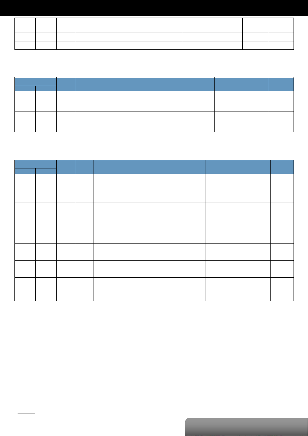
P. 29
| OME-ET-7000/OME-PET-7000 Series
OME-ET-7019/OME-PET-7019
00830
033E
1
Enable/Disable the AI calibration
0: Disable
1: Enable
R/W
-
00831
033F
1
Zero calibration for channel 0
1: Active W -
00832
0340
1
Span calibration for channel 0
1: Active W -
Register
Points
Description
Data Format
Attribute
DEC
HEX
10224
:
10231
00E0
:
00E7
8
Read AI high alarm status.
When the AI value is higher than the high alarm value, the status becomes 1.
0: Normal
1: Alarmed
R
10256
:
10263
0100
:
0107
8
Read AI low alarm status.
When the AI value is lower than the high alarm value, the status becomes 1.
0: Normal
1: Alarmed
R
Register
Points
No. Per
Point
Description
Data Format
Attribute
DEC
HEX
30000
:
30007
0000
:
0007
8 1 AI value
-32768 to 32767
(0x0000 to 0xFFFF)
R
30143
008F 1 1
CJC value
-32768 to 32767
R
30236
:
30243
00EC
:
00F3
8 1 AI historical max. value
-32768 to 32767
(0x0000 to 0xFFFF)
R
30268
:
30275
010C
:
0113
8 1 AI historical min. value
-32768 to 32767
(0x0000 to 0xFFFF)
R
30310
0136 1 1
Number of the DO channel
4
R
30320
0140 1 1
Number of the AI channel
8 R 30350
015E 1 1
OS image version
0x123 means version 1.2.3
R
30351
015F 1 1
Firmware version
0x123 means version 1.2.3
R
30353
0161 1 1
I/O version
0x123 means version 1.2.3
R
30360
0168 1 1
Communication state of the pair-connection
0: Normal
<0: Failed
R
Discrete Inputs (1xxxx)
Input Register (3xxxx)
Page 33
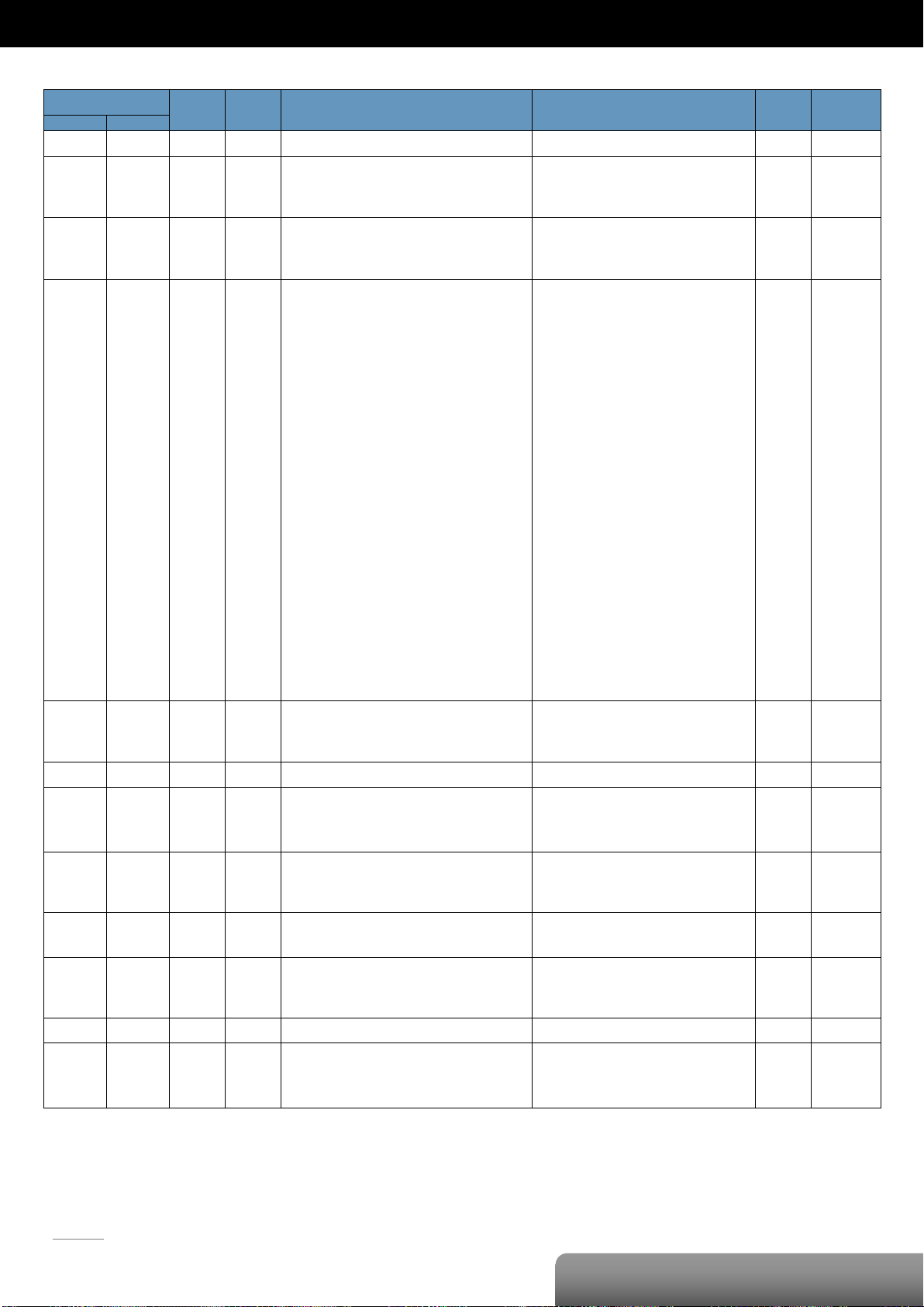
P. 30
| OME-ET-7000/OME-PET-7000 Series
OME-ET-7019/OME-PET-7019
Register
Points
No. Per
Point
Description
Data Format
Attribute
Factory Value
DEC
HEX
40271
010F 1 1
Set the module identification (Modbus NetID)
1 to 255
R/W/E
1
40296
:
40303
0128
:
012F
8 1 Set the AI high alarm value
-32768 to 32767
(0x0000 to 0xFFFF)
R/W/E
32767
(0x7FFF)
40328
:
40335
0148
:
014F
8 1 Set the AI low alarm value
-32768 to 32767
(0x0000 to 0xFFFF)
R/W/E
-32768
(0x8000)
40427
:
40434
01AB
:
01B2
8 1 Set the AI range
0x00: +/-15 mV
0x01: +/-50 mV
0x02: +/-100 mV
0x03: +/-500 mV
0x04: +/-1 V
0x05: +/-2.5 V
0x06: +/-20 mA
0x07: 4 ~ 20 mA
0x0E: Type J, -210°C ~ 760°C
0x0F: Type K, -270°C ~ 1372°C
0x10: Type T, -270°C ~ 400°C
0x11: Type E, -270°C ~ 1000°C
0x12: Type R, 0°C ~ 1768°C
0x13: Type S, 0°C ~ 1768°C
0x14: Type B, 0°C ~ 1820°C
0x15: Type N, -270°C ~ 1300°C
0x16: Type C, 0°C ~ 2320°C
0x17: Type L, -200°C ~ 800°C
0x18: Type M, -200°C ~ 100°C
0x19: Type L DIN43710, -200°C ~ 900°C
0x1A: 0 ~ 20 mA
R/W/E
0x05
40491
:
40598
01EB
:
01F2
8 1 Set the CJC Offset for the single channel
-9999 to 9999
R/W/E
0
40523
020B 1 1
Set the CJC Offset for all channels
-9999 to 9999
R/W/E
0
40555
022B 1 1
Read the module reset status
1: Power-on
2: Module Watchdog
3: Software Reset Command
R
-
40556
022C 1 1
Read the boot count of the module
The factory default value is 0 when the
settings are set to the factory default values.
1 to 32767
R
-
40557
022D 1 1
Set the Host WDT timeout (unit: second)
0: Disable the Host WDT
5 to 65535: Enable the Host WDT
R/W/E
0
40558
022E 1 1
Read the WDT event count
The initial value is 0 when the module is reset,
and is increased when the WDT even happens.
0 to 32767
R
-
40559
022F 1 1
Read the module name
0x7019 R -
40589
024D 1 1
Set the CJC operation status
0: Stop
1: Start
2: Read once
R/W/E
1
Holding Register (4xxxx)
Page 34
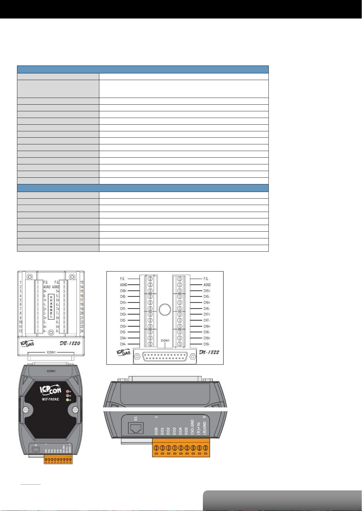
P. 31
| OME-ET-7000/OME-PET-7000 Series
OME-ET-7019Z/OME-PET-7019Z
Analog Input
Input Channels
10 (Differential)
Input Type
+/-15 mV, +/-50 mV, +/-100 mV, +/-150 mV, +/-500 mV, +/-1 V, +/-2.5V, +/-5 V, +/-10 V
0~20 mA, +/-20 mA, 4~20 mA (Jumper Selectable)
Thermocouple (J, K, T, E, R, S, B, N, C, L, M and LDIN43710)
Individual Channel Configuration
Yes
Resolution
16-bit
Sampling Rate
10 Samples/Sec. (Total)
Accuracy
+/-0.1% or better
Zero Drift
+/-0.5 uV/°C
Span Drift
+/-25 ppm/°C
Overvoltage Protection
240 Vrms
Input Impedance
>300 KΩ
Common Mode Rejection
86 dB Min.
Normal Mode Rejection
100 dB
Temperature Outputs Consistency
Yes
Stable Temperature Output In The Field
Yes
Open Wire Detection
Yes
Digital Output
Output Channels
6
Type
Isolated Open Collector (Sink)
Max. Load Current
700 mA/Channel
Load Voltage
5 VDC~50 VDC
Overvoltage Protection
60 VDC
Overload Protection
1.4 A
Short-circuit Protection
Yes
Power-on Value
Yes, Programmable
Safe Value
Yes, Programmable
OME-ET-7019Z/OME-PET-7019Z
I/O Specifications
Pin Assignments
Page 35
P. 32
| OME-ET-7000/OME-PET-7000 Series
OME-ET-7019Z/OME-PET-7019Z
Voltage Input
Thermocouple Input
Current Input
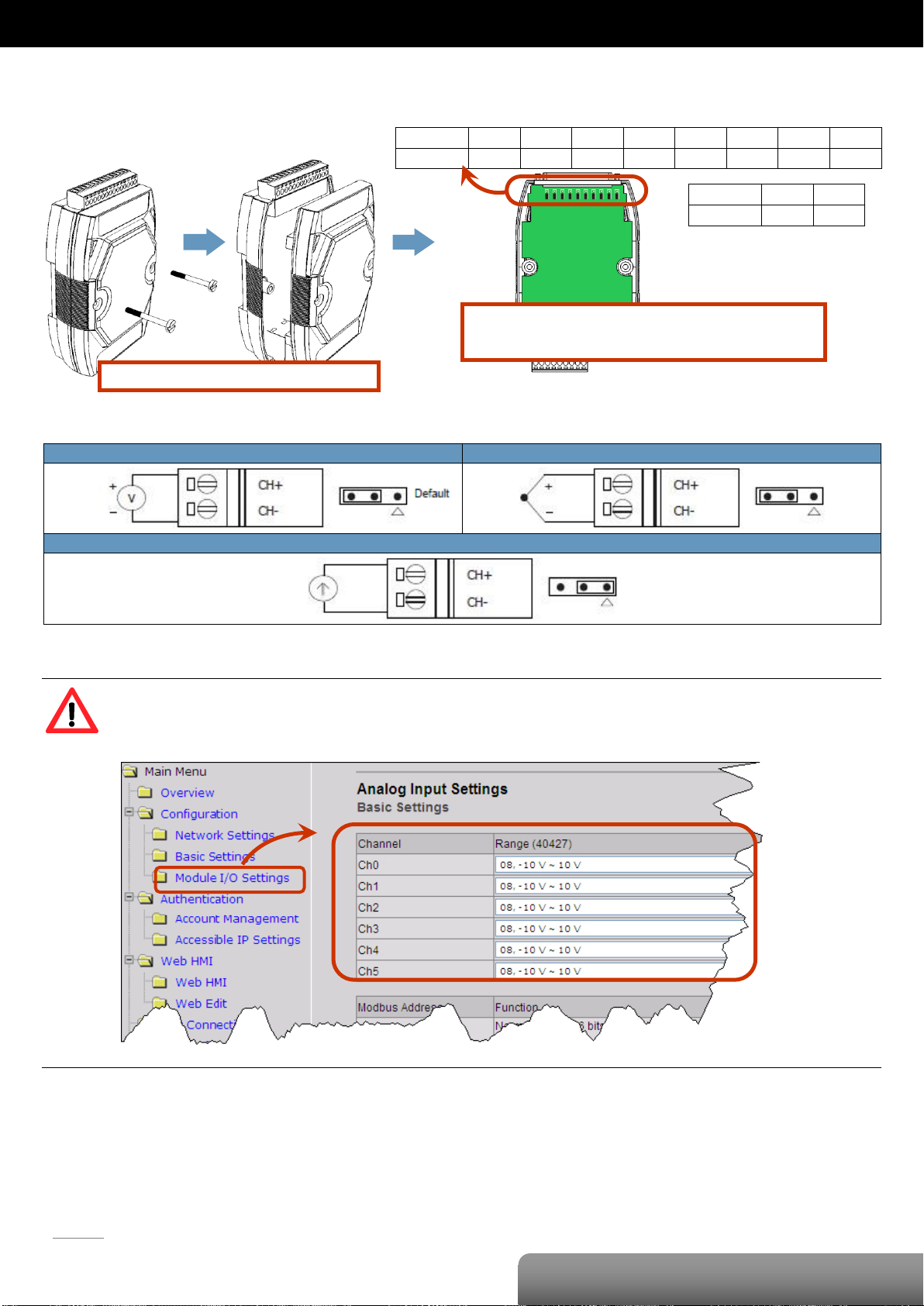
Remove the top case of the module.
The selection jumpers are next to the connector.
Refer to the table below to set the input type.
Channel
CH0 ±
CH1 ±
CH2±
CH3±
CH4±
CH5±
CH6±
CH7±
Jumper
J1
J2
J3
J4
J5
J6
J7
J8
Channel
CH8 ±
CH9 ±
Jumper
J9
J10
Voltage/Current Input Selection Jumper Settings
Tips & Warnings
The jumper settings of the input type for each AI channel must correspond to the input range for each AI
channel of the web interface.
Page 36

P. 33
| OME-ET-7000/OME-PET-7000 Series
OME-ET-7019Z/OME-PET-7019Z
Digital Output
ON State
Readback as 1
OFF State
Readback as 0
Open Collector (Sink)
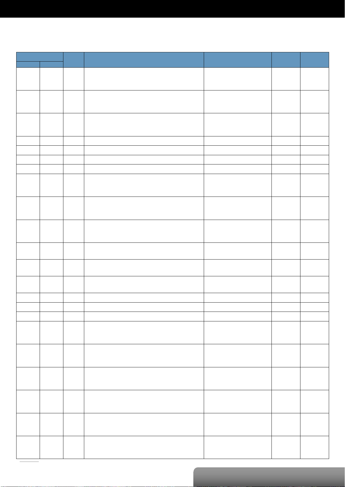
Wire Connections
Page 37
P. 34
| OME-ET-7000/OME-PET-7000 Series
OME-ET-7019Z/OME-PET-7019Z
Register
Points
Description
Data Format
Attribute
Factory Value
DEC
HEX
00000
:
00005
0000
:
0005
6
DO value
0: Off
1: On
R/W
-
00162
:
00171
00A2
:
00AB
10
Clear 1-ch historical AI max. value
1: Clear W -
00194
:
00203
00C2
:
00CB
10
Clear 1-ch historical AI min. value
1: Clear W -
00226
00E2
1
Reset the I/O settings to the factory default state
1: Reset W -
00233
00E9
1
Reboot the module
1: Reboot W -
00431
01AF
1
Save the DO power-on value to the EEPROM
1: Save
W/E
-
00432
01B0
1
Save the DO safe value to the EEPROM
1: Save
W/E
-
00435
:
00440
01B3
:
01B8
6
Enable/Disable the DO power-on value function
0: Disable
1: Enable
R/W
0
00515
:
00520
0203
:
0208
6
Enable/Disable the DO safe value function
0: Disable
1: Enable
R/W
0
00595
:
00604
0253
:
025C
10
Enable/Disable the AI function
0: Disable
1: Enable
R/W/E
1
00627
0273
1
Enable/Disable the CJC function
0: Disable
1: Enable
R/W/E
1
00629
0275
1
Set the AI noise filter
0: Frequency 60 Hz
1: Frequency 50 Hz
R/W/E
0
00631
0277
1
Set the AI data format
0: Hexadecimal format
1: Engineering unit
R/W/E
0
00632
0278
1
Reset the AI calibration to the factory settings
1: Reset W -
00634
027A
1
Clear all historical AI max. values
1: Clear W -
00635
027B
1
Clear all historical AI min. values
1: Clear W -
00636
:
00645
027C
:
0285
10
Enable/Disable the AI high alarm function
0: Disable
1: Enable
R/W/E
0
00668
:
00677
029C
:
02A5
10
Enable/Disable the AI low alarm function
0: Disable
1: Enable
R/W/E
0
00700
:
00709
02BC
:
02C5
10
Set the AI high alarm mode
0: Momentary mode
1: Latching mode
R/W/E
0
00732
:
00741
02DC
:
02E5
10
Set the AI low alarm mode
0: Momentary mode
1: Latching mode
R/W/E
0
00764
:
00773
02FC
:
0305
10
Clear the AI high alarm status
1: Clear W -
00796
:
00805
031C
:
0325
10
Clear the AI low alarm status
1: Clear W -
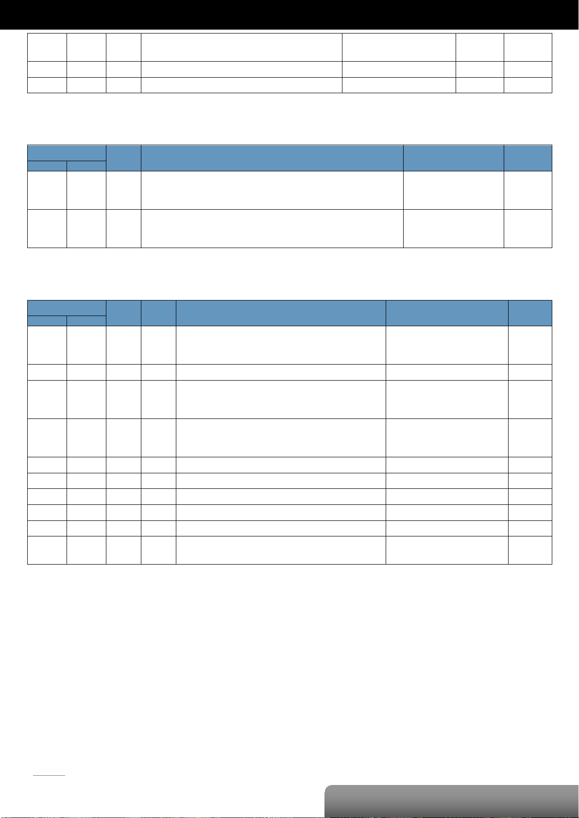
Modbus Register Table
Coils (0xxxx)
Page 38
P. 35
| OME-ET-7000/OME-PET-7000 Series
OME-ET-7019Z/OME-PET-7019Z
00830
033E
1
Enable/Disable the AI calibration
0: Disable
1: Enable
R/W
-
00831
033F
1
Zero calibration for the channel 0
1: Set W -
00832
0340
1
Span calibration for the channel 0
1: Set W -
Register
Points
Description
Data Format
Attribute
DEC
HEX
10224
:
10233
00E0
:
00E9
10
Read AI high alarm status.
When the AI value is higher than the high alarm value, the status becomes 1.
0: Normal
1: Alarmed
R
10256
:
10265
0100
:
0109
10
Read AI low alarm status.
When the AI value is lower than the high alarm value, the status becomes 1.
0: Normal
1: Alarmed
R
Register
Points
No. Per
Point
Description
Data Format
Attribute
DEC
HEX
30000
:
30009
0000
:
0009
10 1 AI value
-32768 to 32767
(0x0000 to 0xFFFF)
R
30143
008F 1 1
CJC value
-32768 to 32767
R
30236
:
30245
00EC
:
00F5
10 1 AI historical max. value
-32768 to 32767
(0x0000 to 0xFFFF)
R
30268
:
30277
010C
:
0115
10 1 AI historical min. value
-32768 to 32767
(0x0000 to 0xFFFF)
R
30310
0136 1 1
Number of the DO channel
6
R
30320
0140 1 1
Number of the AI channel
10 R 30350
015E 1 1
OS image version
0x123 means version 1.2.3
R
30351
015F 1 1
Firmware version
0x123 means version 1.2.3
R
30353
0161 1 1
I/O version
0x123 means version 1.2.3
R
30360
0168 1 1
Communication state of the pair-connection
0: Normal
<0: Failed
R
Discrete Inputs (1xxxx)
Input Register (3xxxx)
Page 39

P. 36
| OME-ET-7000/OME-PET-7000 Series
OME-ET-7019Z/OME-PET-7019Z
Register
Points
No. Per
Point
Description
Data Format
Attribute
Factory Value
DEC
HEX
40271
010F 1 1
Set the module identification (Modbus NetID)
1 to 255
R/W/E
1
40296
:
40305
0128
:
0131
10 1 Set the AI high alarm value
-32768 to 32767
(0x0000 to 0xFFFF)
R/W/E
32767
(0x7FFF)
40328
:
40337
0148
:
0151
10 1 Set the AI low alarm value
-32768 to 32767
(0x0000 to 0xFFFF)
R/W/E
-32768
(0x8000)
40427
:
40436
01AB
:
01B4
10 1 Set the AI range
0x00: +/-15 mV
0x01: +/-50 mV
0x02: +/-100 mV
0x03: +/-500 mV
0x04: +/-1 V
0x05: +/-2.5 V
0x06: +/-20 mA
0x07: 4 ~ 20 mA
0x08: +/-10 V
0x09: +/-5 V
0x0A: +/-1V
0x0B: +/-500 mV
0x0C: +/-150 mV
0x0D: +/-20 mA
0x0E: Type J, -210°C ~ 760°C
0x0F: Type K, -270°C ~ 1372°C
0x10: Type T, -270°C ~ 400°C
0x11: Type E, -270°C ~ 1000°C
0x12: Type R, 0°C ~ 1768°C
0x13: Type S, 0°C ~ 1768°C
0x14: Type B, 0°C ~ 1820°C
0x15: Type N, -270°C ~ 1300°C
0x16: Type C, 0°C ~ 2320°C
0x17: Type L, -200°C ~ 800°C
0x18: Type M, -200°C ~ 100°C
0x19: Type L DIN43710, -200°C ~ 900°C
0x1A: 0 ~ 20 mA
R/W/E
0x05
40491
:
40500
01EB
:
01F4
10 1 Set the CJC Offset for the single channel
-9999 to 9999
R/W/E
0
40523
020B 1 1
Set the CJC Offset for all channels
-9999 to 9999
R/W/E
0
40555
022B 1 1
Read the module reset status
1: Power-on
2: Module Watchdog
3: Software Reset Command
R
-
40556
022C 1 1
Read the boot count of the module
The factory default value is 0 when the
settings are set to the factory default values.
1 to 32767
R
-
40557
022D 1 1
Set the Host WDT timeout (unit: second)
0: Disable the Host WDT
5 to 65535: Enable the Host WDT
R/W/E
0
40558
022E 1 1
Read the WDT event count
The initial value is 0 when the module is reset,
and is increased when the WDT even happens.
0 to 32767
R
-
40559
022F 1 1
Read the module name
0x7019 R -
40589
024D 1 1
Set the CJC operation status
0: Stop
1: Start
2: Read once
R/W/E
1
Holding Register (4xxxx)
Page 40
P. 37
| OME-ET-7000/OME-PET-7000 Series
OME-ET-7026/OME-PET-7026
Analog Input
Input Channels
6 (Differential)
Input Type
+/-500 mV, +/-1 V, +/-5 V, +/-10 V, 0~20 mA,
+/-20 mA, 4~20 mA (jumper selectable)
Individual Channel Configuration
Yes
Resolution
Normal Mode
16-bit
Fast Mode
12-bit
Sampling Rate
Normal Mode
10 Samples/Sec. (Total)
Fast Mode
60 Samples/Sec. (Total)
Accuracy
Normal Mode
+/-0.1%
Fast Mode
+/-0.5% or better
Zero Drift
+/-20 uV/°C or better
Span Drift
+/-25 ppm/°C
Overvoltage Protection
240 Vrms
Input Impedance
2 MΩ
Common Mode Rejection
86 dB Min.
Normal Mode Rejection
100 dB
Analog Output
Output Channels
2
Output Type
0~5 V, +/-5 V, 0~10 V, +/-10 V
0~20 mA, 4~20 mA (jumper selectable)
Individual Channel Configuration
Yes
Resolution
12-bit
Accuracy
+/-0.1% of FSR
Voltage Output Capability
20 mA @ 10 V
Current Load Resistance
500 Ω
Open Wire Detection
Yes, for 4~20 mA only
Power On Value
Yes, Programmable
Safe Value
Yes, Programmable
Digital Input/Counter
Input Channels
2
Dry Contact
(Source)
On Voltage Level
Close to GND
Off Voltage Level
Open
Effective Distance
for Dry Contact
500M max.
Wet Contact
(Sink/Source)
On Voltage Level
+3.5 VDC ~ +30VDC
Off Voltage Level
+1 VDC max.
Counter
Channels
2
Max. Counts
4,294,967,285 (32-bit)
Max. Input
Frequency
100 Hz
Min. Pulse Width
5 ms
Overvoltage Protection
30 VDC
Digital Output
Output Channels
2
Type
Isolated Open Collector (Sink)
Max. Load Current
700 mA/Channel
Load Voltage
+5 VDC ~ +50 VDC
Overvoltage Protection
60 VDC
Overload Protection
1.4 A
Short-circuit Protection
Yes
Power-on Value
Yes, Programmable
Safe Value
Yes, Programmable
OME-ET-7026/OME-PET-7026
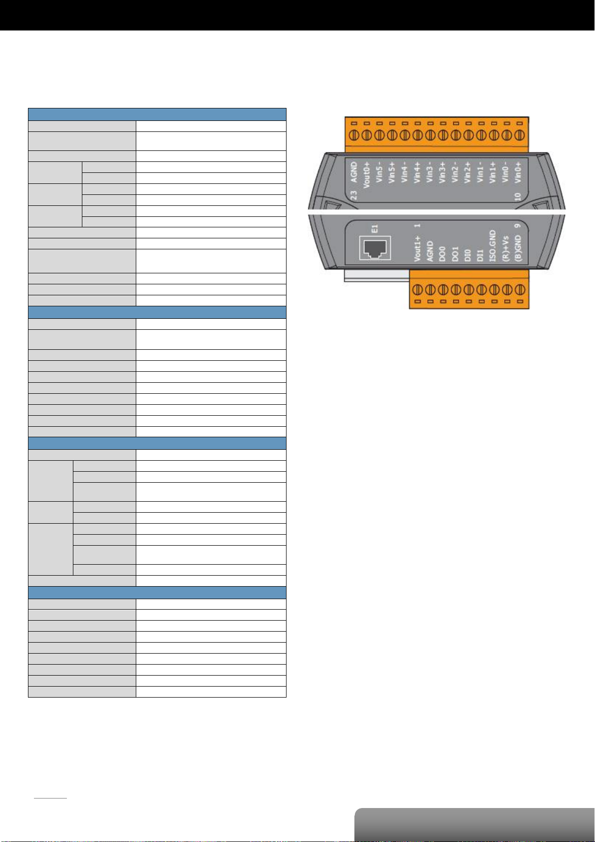
I/O Specifications
Pin Assignments
Page 41
|OME‐ET‐7000/OME‐PET‐7000Series
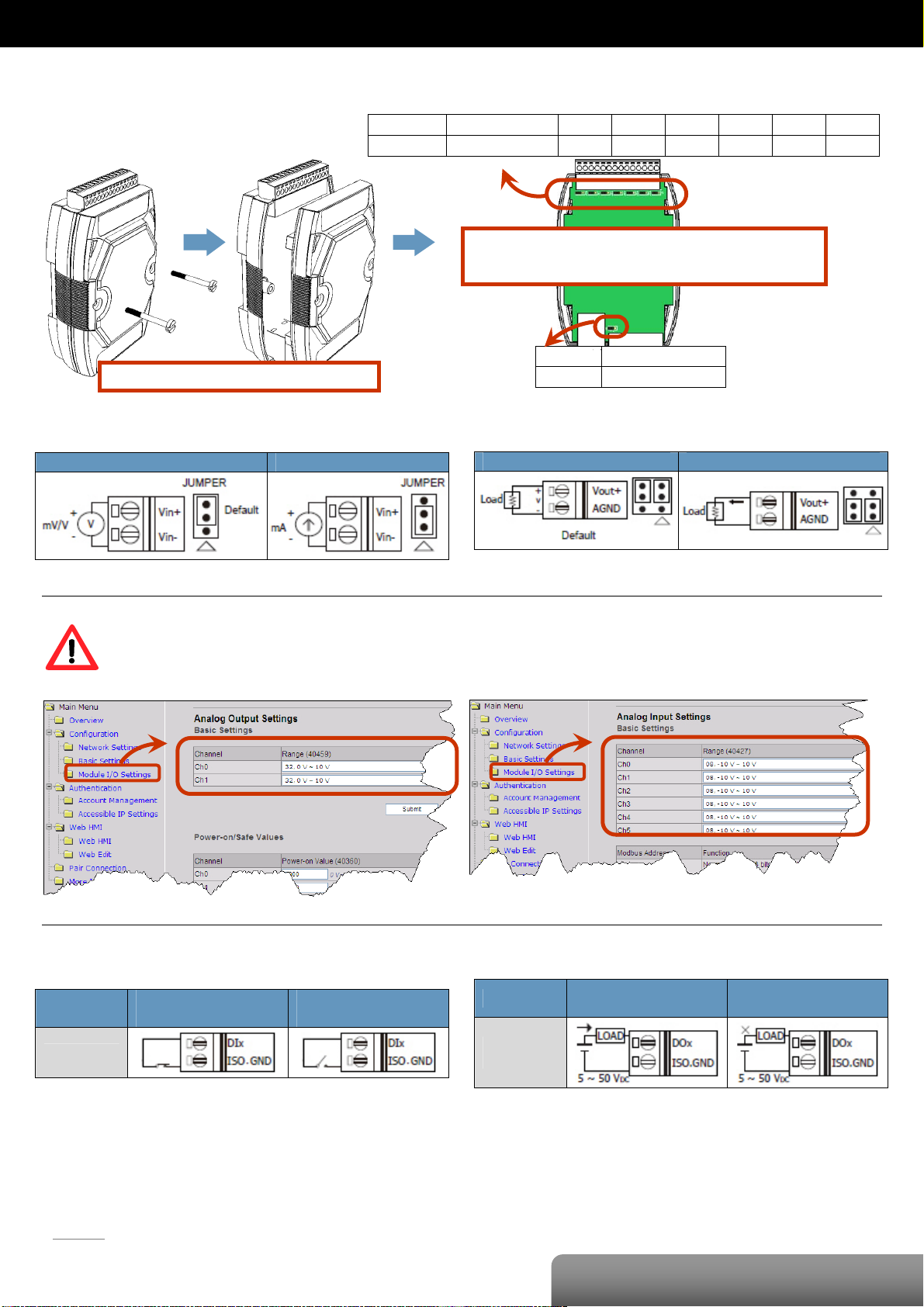
Voltage/CurrentInput/OutputSelectionJumperSettings
Channel Vout0 & AGND Vin5 ± Vin4 ± Vin3 ± Vin2 ± Vin1 ± Vin0 ±
Jumper JP5 J6 J5 J4 J3 J2 JP1
The selection jumpers are next to the connector.
Refer to the table below to set the input type.
Remove the top case of the module.
Channel Vout1+ & AGND
Jumper JP6
Voltage Input Current Input
The jumper settings of the input type for each AI/AO channel must correspond to the input range for each
AI/AO channel of the web interface.
Voltage Output Current Output
WireConnections
Digital Input/
Counter
Dry Contact
ON State
Readback as 1
OFF State
Readback as 0
Digital Output
Open Collector
(Sink)
ON State
Readback as 1
OFF State
Readback as 0
P. 38
OME‐ET‐7026/OME‐PET‐7026
Page 42
P. 39
| OME-ET-7000/OME-PET-7000 Series
OME-ET-7026/OME-PET-7026
Register
Points
Description
Data Format
Attribute
Factory Value
DEC
HEX
00000
:
00001
0000
:
0001
2
DO value
0: Off
1: On
R/W
-
00034
:
00035
0022
:
0023
2
Clear the DI counter value
1: Clear W -
00130
:
00131
0082
:
0083
2
Clear the DI latched value
1: Clear W -
00162
:
00167
00A2
:
00A7
6
Clear 1-ch historical AI max. value
1: Clear W -
00194
:
00199
00C2
:
00C7
6
Clear 1-ch historical AI min. value
1: Clear W -
00226
00E2
1
Reset the I/O settings to the factory default state
1: Reset W -
00233
00E9
1
Reboot the module
1: Reboot W -
00350
015E
1
Enable/Disable the DI latch function
0: Disable
1: Enable
R/W/E
0
00351
:
00352
015F
:
0160
2
Enable/Disable the DI counter function
0: Disable
1: Enable
R/W/E
0
00431
01AF
1
Save the DO power-on value to the EEPROM
1: Save
W/E
-
00432
01B0
1
Save the DO safe value to the EEPROM
1: Save
W/E
-
00435
:
00436
01B3
:
01B4
2
Enable/Disable the DO power-on value function
0: Disable
1: Enable
R/W
0
00515
:
00516
0203
:
0204
2
Enable/Disable the DO safe value function
0: Disable
1: Enable
R/W
0
00595
:
00560
0253
:
0258
6
Enable/Disable the AI function
0: Disable
1: Enable
R/W/E
1
00628
0274
1
Set the AI sampling rate
0: Normal mode (10 Hz, 16 bits)
1: Fast mode (60 Hz, 12 bits)
R/W/E
0
00629
0275
1
Set the AI noise filter
0: Frequency 60 Hz
1: Frequency 50 Hz
R/W/E
0
00630
0276
1
Save preset values for the DI counter to the EEPROM
1: Save
W/E
-
00631
0277
1
Set the AI/AO data format
0: Hexadecimal format
1: Engineering unit
R/W/E
0
00632
0278
1
Reset the AI calibration to the factory settings
1: Reset W -
00634
027A
1
Clear all historical AI max. values
1: Clear W -
00635
027B
1
Clear all historical AI min. values
1: Clear W -
00636
:
00641
027C
:
0281
6
Enable/Disable the AI high alarm function
0: Disable
1: Enable
R/W/E
0
00668
:
029C
:
6
Enable/Disable the AI low alarm function
0: Disable
1: Enable
R/W/E
0
Modbus Register Table
Coils (0xxxx)
Page 43
P. 40
| OME-ET-7000/OME-PET-7000 Series
OME-ET-7026/OME-PET-7026
00670
02A1
00700
:
00705
02BC
:
02C1
6
Set the AI high alarm mode
0: Momentary mode
1: Latching mode
R/W/E
0
00732
:
00737
02DC
:
02E1
6
Set the AI low alarm mode
0: Momentary mode
1: Latching mode
R/W/E
0
00764
:
00769
02FC
:
0301
6
Clear the AI high alarm status
1: Clear W -
00796
:
00801
031C
:
0321
6
Clear the AI high low status
1: Clear W -
00830
033E
1
Enable/Disable the AI calibration
0: Disable
1: Enable
R/W
-
00831
033F
1
Zero calibration for the channel 0
1: Set W -
00832
0340
1
Span calibration for the channel 0
1: Set W -
Register
Points
Description
Data Format
Attribute
DEC
HEX
10000
:
10001
0000
:
0001
2
DI value
0: Off
1: On
R
10032
:
10033
0020
:
0021
2
Read DI “high latch” status
0: Normal
1: Latched
R
10064
:
10065
0040
:
0041
2
Read DI “low latch” status
0: Normal
1: Latched
R
10224
:
10229
00E0
:
00E5
6
Read AI high alarm status.
When the AI value is higher than the high alarm value, the status becomes 1.
0: Normal
1: Alarmed
R
10256
:
10261
0100
:
0105
6
Read AI low alarm status.
When the AI value is lower than the high alarm value, the status becomes 1.
0: Normal
1: Alarmed
R
Discrete Inputs (1xxxx)
Page 44
P. 41
| OME-ET-7000/OME-PET-7000 Series
OME-ET-7026/OME-PET-7026
Register
Points
No. Per
Point
Description
Data Format
Attribute
DEC
HEX
30000
:
30005
0000
:
0005
6 1 AI value
-32768 to 32767
(0x0000 to 0xFFFF)
R
30032
:
30035
0020
:
0023
2 2 DI counter value
0 to 4294967295
R
30236
:
30241
00EC
:
00F1
6 1 AI historical max. value
-32768 to 32767
(0x0000 to 0xFFFF)
R
30268
:
30273
010C
:
0111
6 1 AI historical min. value
-32768 to 32767
(0x0000 to 0xFFFF)
R
30300
012C 1 1
Number of the DI channel
6
R
30310
0136 1 1
Number of the DO channel
2
R
30320
0140 1 1
Number of the AI channel
2 R 30330
014A 1 1
Number of the AO channel
2 R 30350
015E 1 1
OS image version
0x123 means version 1.2.3
R
30351
015F 1 1
Firmware version
0x123 means version 1.2.3
R
30353
0161 1 1
I/O version
0x123 means version 1.2.3
R
30360
0168 1 1
Communication state of the pair-connection
0: Normal
<0: Failed
R
Input Register (3xxxx)
Page 45

P. 42
| OME-ET-7000/OME-PET-7000 Series
OME-ET-7026/OME-PET-7026
Register
Points
No. Per
Point
Description
Data Format
Attribute
Factory Value
DEC
HEX
40000
:
40001
0000
:
0001
2 1 AO value
-32768 to 32767
(0x0000 to 0xFFFF)
R/W
-
40200
:
40203
00C8
:
00CB
2
2
Set a preset value for the DI Counter
Any values updated based on the Modbus
communication will not take immediate effect
and not be saved to EEPROM until the register
(00630) is changed by a write operation.
0 to 4294967295
R/W
0
40271
010F 1 1
Set the module identification (Modbus NetID)
1 to 255
R/W/E
1
40296
:
40301
0128
:
012D
6 1 Set the AI high alarm value
-32768 to 32767
(0x0000 to 0xFFFF)
R/W/E
32767
(0x7FFF)
40328
:
40333
0148
:
014D
6 1 Set the AI low alarm value
-32768 to 32767
(0x0000 to 0xFFFF)
R/W/E
-32768
(0x8000)
40360
:
40361
0168
:
0169
2 1 Set the power-on value for the AO channel
-32768 to 32767
(0x0000 to 0xFFFF)
R/W/E
0
40392
:
40393
0188
:
0189
2 1 Set the safe value for the AO channel
-32768 to 32767
(0x0000 to 0xFFFF)
R/W/E
0
40427
:
40432
01AB
:
01B0
6 1 Set the AI range
0x07: 4~20 mA
0x08: +/-10 V
0x09: +/-5 V
0x0A: +/-1 V
0x0B: +/-500 mV
0x0C: +/-150 mV
0x0D: +/-20 mA
0x1A: 0~20 mA
R/W/E
0x08
40459
:
40460
01CB
:
01CC
2 1 Set the AO range
0x30: 0~20 mA
0x31: 4~20 mA
0x32: 0~10 V
0x33: +/-10 V
0x34: 0~5 V
0x35: +/-5 V
R/W/E
0x32
40523
:
40524
020B
:
020C
2 1 Set the AO slew rate range
0x00: Immediate
0x01: 0.0625 V/sec or 0.125 mA/sec
0x02: 0.125 V/sec or 0.25 mA/sec
0x03: 0.25 V/sec or 0.5 mA/sec
0x04: 0.5 V/sec or 1.0 mA/sec
0x05: 1.0 V/sec or 2.0 mA/sec
0x06: 2.0 V/sec or 4.0 mA/sec
0x07: 4.0 V/sec or 8.0 mA/sec
0x08: 8.0 V/sec or 16 mA/sec
0x09: 16 V/ser or 32 mA/sec
0x10: 32 V/sec or 64 mA/sec
0x11: 64 V/sec or 128 mA/sec
0x12: 128 V/sec or 256 mA/sec
0x13: 256 V/sec or 512 mA/sec
0x14: 512 V/sec or 1024 mA/sec
R/W/E
0x00
40555
022B 1 1
Read the module reset status
1: Power-on
2: Module Watchdog
3: Software Reset Command
R
-
40556
022C 1 1
Read the boot count of the module
1 to 32767 R -
Holding Register (4xxxx)
Page 46

P. 43
| OME-ET-7000/OME-PET-7000 Series
OME-ET-7026/OME-PET-7026
The factory default value is 0 when the
settings are set to the factory default values.
40557
022D 1 1
Set the Host WDT timeout (unit: second)
0: Disable the Host WDT
5 to 65535: Enable the Host WDT
R/W/E
0
40558
022E 1 1
Read the WDT event count
The initial value is 0 when the module is reset,
and is increased when the WDT even happens.
0 to 32767 R -
40559
022F 1 1
Read the module name
0x7026 R -
Page 47
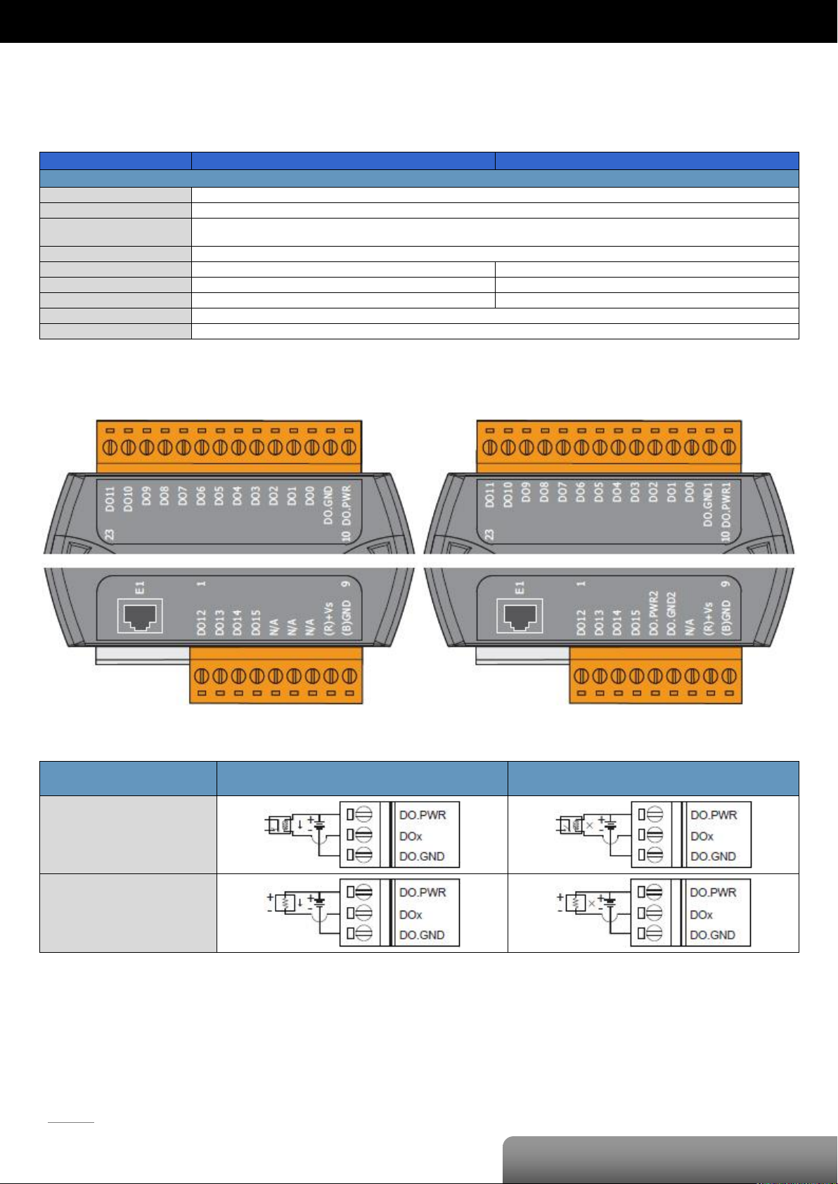
P. 44
OME-ET-7042/OME-PET-7042
| OME-ET-7000/OME-PET-7000 Series
Model
OME-ET-7042
OME-PET-7042
Digital Output
Output Channels
16
Type
Isolated Open Collector (Sink)
Max. Load Current
100 mA/Channel at 25°C
Direct drive power relay module
Load Voltage
+5 VDC ~ +30 VDC
Overvoltage Protection
-
60 VDC
Overload Protection
-
1.3 A
Short-circuit Protection
-
Yes
Power-on Value
Yes, Programmable
Safe Value
Yes, Programmable
ET-7042
PET-7042
Digital Output
ON State
Readback as 1
OFF State
Readback as 0
Drive Relay
Resistance Load
OME-ET-7042/OME-PET-7042
I/O Specifications
Pin Assignments
Wire Connection
Page 48
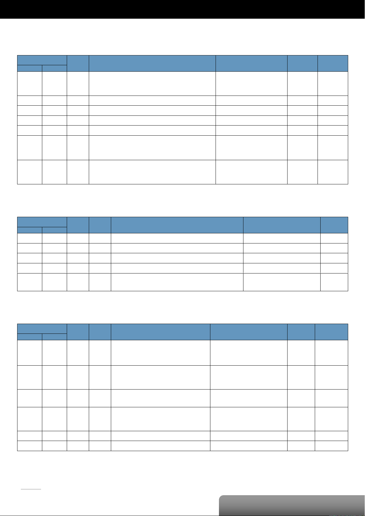
P. 45
OME-ET-7042/OME-PET-7042
| OME-ET-7000/OME-PET-7000 Series
Register
Points
Description
Data Format
Attribute
Factory Value
DEC
HEX
00000
:
00015
0000
:
000F
16
DO value
0: Off
1: On
R/W
-
00126
007E
1
Reset the I/O settings to the factory default state
1: Reset W -
00133
0085
1
Reboot the module
1: Reboot W -
00231
00E7
1
Save the DO power-on value to the EEPROM
1: Save
W/E
-
00232
00E8
1
Save the DO safe value to the EEPROM
1: Save
W/E
-
00235
:
00250
00EB
:
00FA
16
Enable/Disable the DO power-on value function
0: Disable
1: Enable
R/W
0
00267
:
00282
010B
:
011A
16
Enable/Disable the DO safe value function
0: Disable
1: Enable
R/W
0
Register
Points
No. Per
Point
Description
Data Format
Attribute
DEC
HEX
30110
006E 1 1
Number of the DO channel
16
R
30150
0096 1 1
OS image version
0x123 means version 1.2.3
R
30151
0097 1 1
Firmware version
0x123 means version 1.2.3
R
30153
0099 1 1
I/O version
0x123 means version 1.2.3
R
30160
00A0 1 1
Communication state of the pair-connection
0: Normal
<0: Failed
R
Register
Points
No. Per
Point
Description
Data Format
Attribute
Factory Value
DEC
HEX
40255
00FF 1 1
Read the module reset status
1: Power-on
2: Module Watchdog
3: Software Reset Command
R
-
40256
0100 1 1
Read the boot count of the module
The factory default value is 0 when the
settings are set to the factory default values.
1 to 32767 R -
40257
0101 1 1
Set the Host WDT timeout (unit: second)
0: Disable the Host WDT
5 to 65535: Enable the Host WDT
R/W/E
0
40258
0102 1 1
Read the WDT event count
The initial value is 0 when the module is reset,
and is increased when the WDT even happens.
0 to 32767 R -
40260
0104 1 1
Read the module name
0x7042 R -
40271
010F 1 1
Set the module identification (Modbus NetID)
1 to 255
R/W/E
1
Modbus Register Table
Coils (0xxxx)
Input Register (3xxxx)
Holding Register (4xxxx)
Page 49
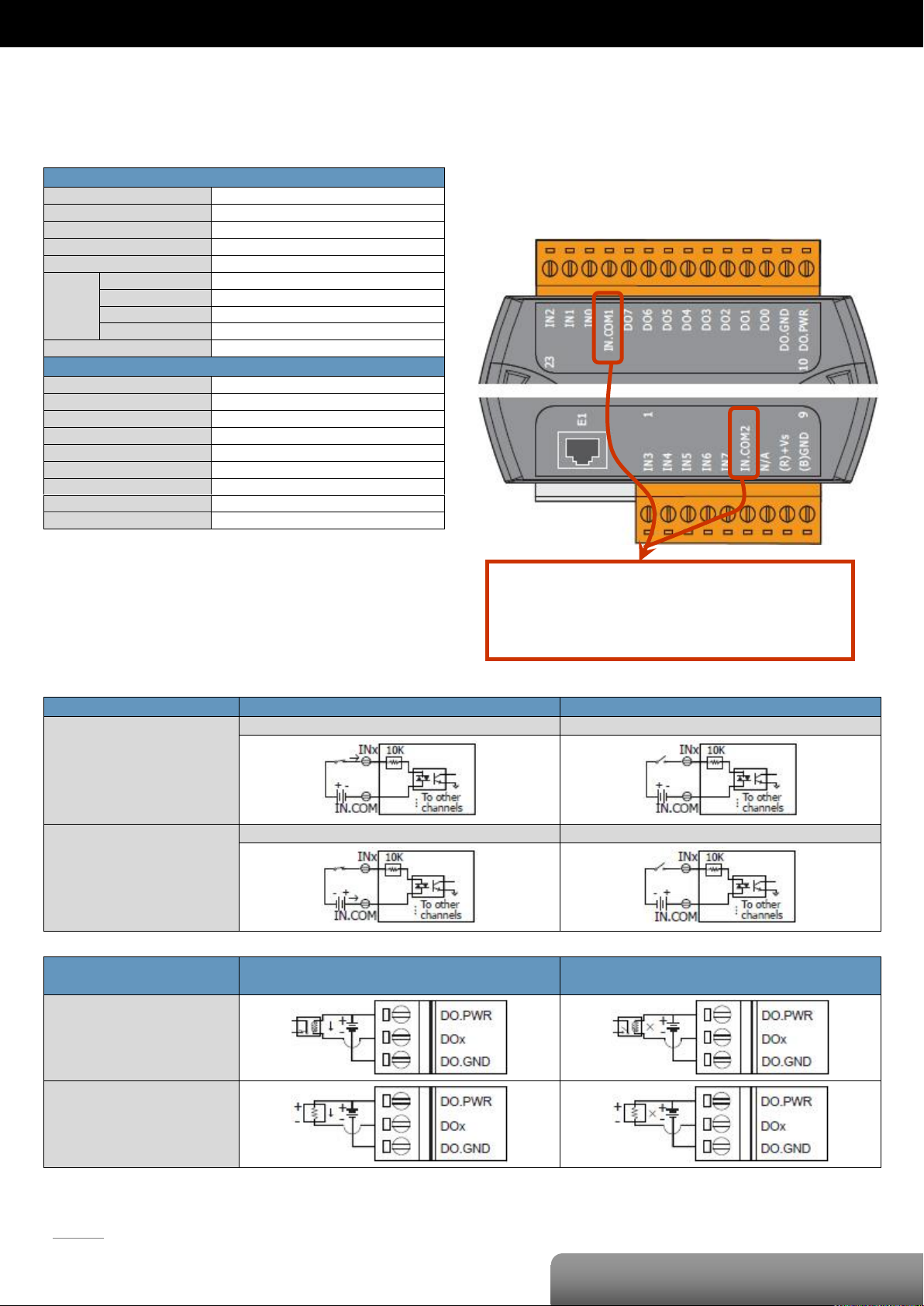
P. 46
OME-ET-7044/OME-PET-7044
| OME-ET-7000/OME-PET-7000 Series
Digital Input/Counter
Input Channels
8
Type
Wet Contact (Sink, Source)
On Voltage Level
+10 VDC ~ +50VDC
Off Voltage Level
+4 VDC max.
Input Impedance
10 KΩ
Counter
Channels
8
Max. Count
4,294,967,285 (32-bit)
Max. Input Frequency
500 Hz
Min. Pulse Width
1 ms
Overvoltage Protection
70 VDC
Digital Output
Output Channels
8
Type
Isolated Open Collector (Sink)
Max. Load Current
300 mA/Channel at 25°C
Load Voltage
+10 VDC ~ +40 VDC
Overvoltage Protection
60 VDC
Overload Protection
1.1 A
Short-circuit Protection
Yes
Power On Value
Yes, Programmable
Safe Value
Yes, Programmable
Digital Input/Counter
Readback as 1
Readback as 0
Sink
+10 ~ +50 VDC
Open or <4 VDC
Source
+10 ~ +50 VDC
Open or <4 VDC
Digital Output
ON State
Readback as 1
OFF State
Readback as 0
Drive Relay
Resistance Load
The IN.COM1 and IN.COM2 of the OME-ET-7044
are internally wired together.
But in the OME-PET-7044, they are separate.
OME-ET-7044/OME-PET-7044
I/O Specifications
Wire Connection
Pin Assignments
Page 50
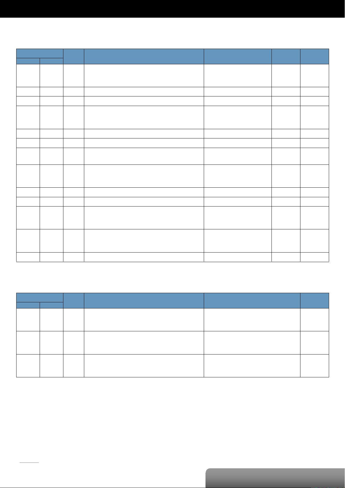
P. 47
OME-ET-7044/OME-PET-7044
| OME-ET-7000/OME-PET-7000 Series
Register
Points
Description
Data Format
Attribute
Factory Value
DEC
HEX
00000
:
00007
0000
:
0007
8
DO value
0: Off
1: On
R/W
-
00032
0020
1
Clear 1-ch historical DI max. value
1: Clear W -
00033
0021
1
Clear 1-ch historical DI min. value
1: Clear W -
00034
:
00041
0022
:
0029
8
Clear the DI counter value
1: Clear W -
00126
007E
1
Reset the I/O settings to the factory default state
1: Reset W -
00133
0085
1
Reboot the module
1: Reboot W -
00150
0096
1
Enable/Disable the DI latch function
0: Disable
1: Enable
R/W/E
0
00151
:
00158
0097
:
009E
8
Enable/Disable the DI counter function
0: Disable
1: Enable
R/W/E
0
00231
00E7
1
Save the DO power-on value to the EEPROM
1: Save
W/E
-
00232
00E8
1
Save the DO safe value to the EEPROM
1: Save
W/E
-
00235
:
00242
00EB
:
00F2
8
Enable/Disable the DO power-on value function
0: Disable
1: Enable
R/W
0
00267
:
00274
010B
:
0112
8
Enable/Disable the DO safe value function
0: Disable
1: Enable
R/W
0
00318
013E
1
Save preset values for the DI counter to the EEPROM
1: Save
W/E
-
Register
Points
Description
Data Format
Attribute
DEC
HEX
10000
:
10007
0000
:
0007
8
DI value
0: Off
1: On
R
10032
:
10039
0020
:
0027
8
Read DI “high latch” status
0: Normal
1: Latched
R
10064
:
10071
0040
:
0047
8
Read DI “low latch” status
0: Normal
1: Latched
R
Modbus Register Table
Coils (0xxxx)
Discrete Inputs (1xxxx)
Page 51
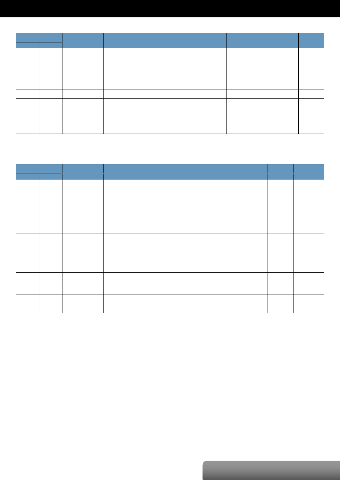
P. 48
OME-ET-7044/OME-PET-7044
| OME-ET-7000/OME-PET-7000 Series
Register
Points
No. Per
Point
Description
Data Format
Attribute
DEC
HEX
30016
:
30031
0010
:
001F
8 2 DI counter value
0 to 4294967295
R
30100
0064 1 1
Number of the DI channel
8
R
30110
006E 1 1
Number of the DO channel
8 R 30150
0096 1 1
OS image version
0x123 means version 1.2.3
R
30151
0097 1 1
Firmware version
0x123 means version 1.2.3
R
30153
0099 1 1
I/O version
0x123 means version 1.2.3
R
30160
00A0 1 1
Communication state of the pair-connection
0: Normal
<0: Failed
R
Register
Points
No. Per
Point
Description
Data Format
Attribute
Factory Value
DEC
HEX
40050
:
40065
0032
:
0041
8
2
Set a preset value for the DI Counter
Any values updated based on the Modbus
communication will not take immediate effect
and not be saved to EEPROM until the register
(00318) is changed by a write operation.
0 to 4294967295
R/W
0
40255
00FF 1 1
Read the module reset status
1: Power-on
2: Module Watchdog
3: Software Reset Command
R
-
40256
0100 1 1
Read the boot count of the module
The factory default value is 0 when the
settings are set to the factory default values.
1 to 32767 R -
40257
0101 1 1
Set the Host WDT timeout (unit: second)
0: Disable the Host WDT
5 to 65535: Enable the Host WDT
R/W/E
0
40258
0102 1 1
Read the WDT event count
The initial value is 0 when the module is reset,
and is increased when the WDT even happens.
0 to 32767 R -
40260
0104 1 1
Read the module name
0x7044 R -
40271
010F 1 1
Set the module identification (Modbus NetID)
1 to 255
R/W/E
1
Input Register (3xxxx)
Holding Register (4xxxx)
Page 52
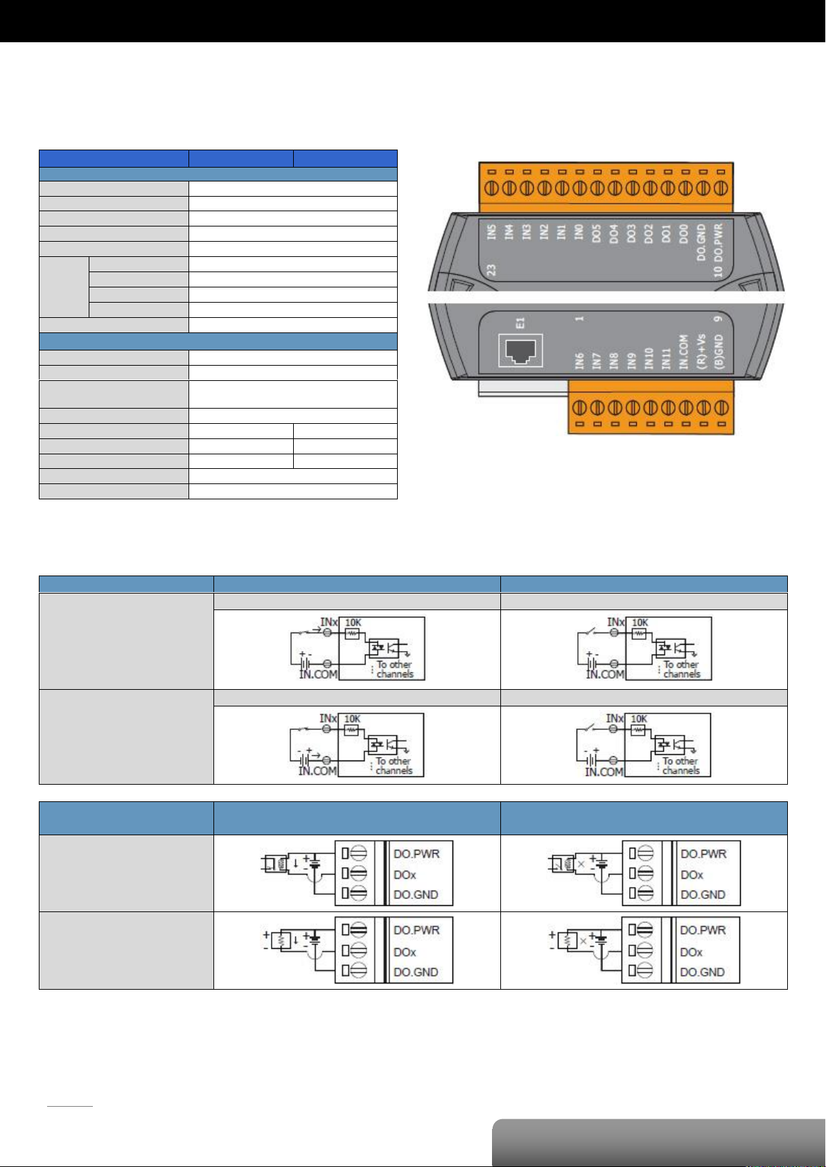
P. 49
OME-ET-7050/OME-PET-7050
| OME-ET-7000/OME-PET-7000 Series
Model
OME-ET-7050
OME-PET-7050
Digital Input/Counter
Input Channels
12
Type
Wet Contact (Sink, Source)
On Voltage Level
+10 VDC ~ +50VDC
Off Voltage Level
+4 VDC max.
Input Impedance
10 KΩ
Counter
Channels
12
Max. Count
4,294,967,285 (32-bit)
Max. Input Frequency
500 Hz
Min. Pulse Width
1 ms
Overvoltage Protection
70 VDC
Digital Output
Output Channels
6
Type
Isolated Open Collector (Sink)
Max. Load Current
100 mA/Channel at 25°C
Direct drive power relay module
Load Voltage
+5 VDC ~ +30 VDC
Overvoltage Protection
-
60 VDC
Overload Protection
-
1.3 A
Short-circuit Protection
-
Yes
Power-on Value
Yes, Programmable
Safe Value
Yes, Programmable
Digital Input/Counter
Readback as 1
Readback as 0
Sink
+10 ~ +50 VDC
Open or <4 VDC
Source
+10 ~ +50 VDC
Open or <4 VDC
Digital Output
ON State
Readback as 1
OFF State
Readback as 0
Drive Relay
Resistance Load
OME-ET-7050/OME-PET-7050
I/O Specifications
Wire Connection
Pin Assignments
Page 53
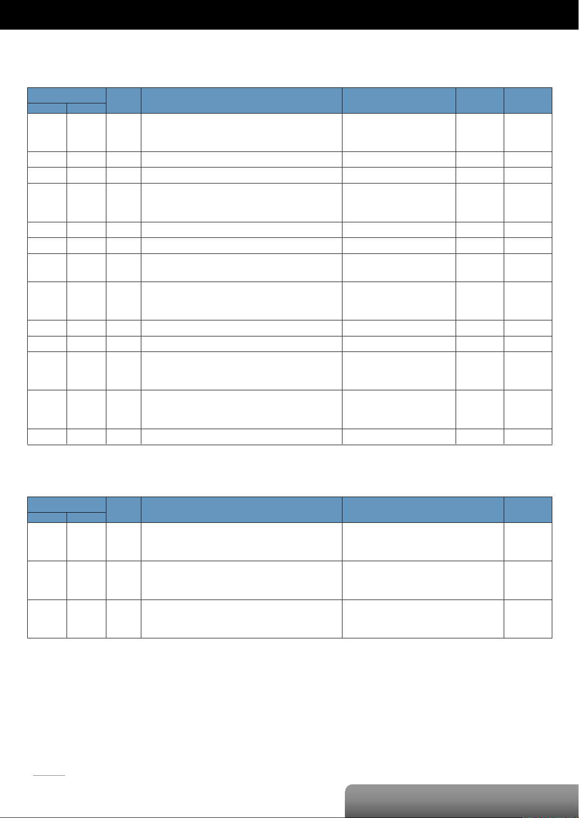
P. 50
OME-ET-7050/OME-PET-7050
| OME-ET-7000/OME-PET-7000 Series
Register
Points
Description
Data Format
Attribute
Factory Value
DEC
HEX
00000
:
00005
0000
:
0005
6
DO value
0: Off
1: On
R/W
-
00032
0020
1
Clear 1-ch historical DI max. value
1: Clear W -
00033
0021
1
Clear 1-ch historical DI min. value
1: Clear W -
00034
:
00045
0022
:
002D
12
Clear the DI counter value
1: Clear W -
00126
007E
1
Reset the I/O settings to the factory default state
1: Reset W -
00133
0085
1
Reboot the module
1: Reboot W -
00150
0096
1
Enable/Disable the DI latch function
0: Disable
1: Enable
R/W/E
0
00151
:
00162
0097
:
00A2
12
Enable/Disable the DI counter function
0: Disable
1: Enable
R/W/E
0
00231
00E7
1
Save the DO power-on value to the EEPROM
1: Save
W/E
-
00232
00E8
1
Save the DO safe value to the EEPROM
1: Save
W/E
-
00235
:
00240
00EB
:
00F0
6
Enable/Disable the DO power-on value function
0: Disable
1: Enable
R/W
0
00267
:
00272
010B
:
0110
6
Enable/Disable the DO safe value function
0: Disable
1: Enable
R/W
0
00318
013E
1
Save preset values for the DI counter to the EEPROM
1: Save
W/E
-
Register
Points
Description
Data Format
Attribute
DEC
HEX
10000
:
10011
0000
:
000B
12
DI value
0: Off
1: On
R
10032
:
10043
0020
:
002B
12
Read DI “high latch” status
0: Normal
1: Latched
R
10064
:
10075
0040
:
004B
12
Read DI “low latch” status
0: Normal
1: Latched
R
Modbus Register Table
Coils (0xxxx)
Discrete Inputs (1xxxx)
Page 54
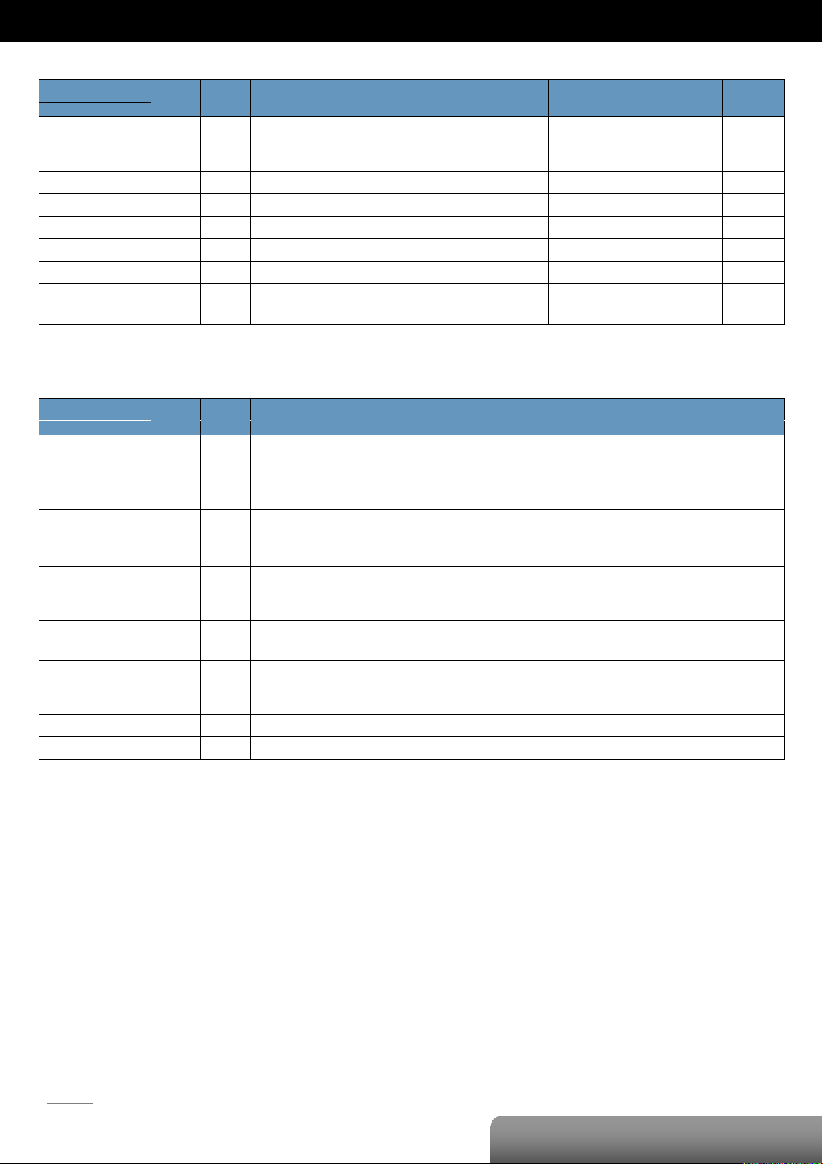
P. 51
OME-ET-7050/OME-PET-7050
| OME-ET-7000/OME-PET-7000 Series
Register
Points
No. Per
Point
Description
Data Format
Attribute
DEC
HEX
30016
:
30039
0010
:
0027
12 2 DI counter value
0 to 4294967295
R
30100
0064 1 1
Number of the DI channel
12
R
30110
006E 1 1
Number of the DO channel
6 R 30150
0096 1 1
OS image version
0x123 means version 1.2.3
R
30151
0097 1 1
Firmware version
0x123 means version 1.2.3
R
30153
0099 1 1
I/O version
0x123 means version 1.2.3
R
30160
00A0 1 1
Communication state of the pair-connection
0: Normal
<0: Failed
R
Register
Points
No. Per
Point
Description
Data Format
Attribute
Factory Value
DEC
HEX
40050
:
40073
0032
:
0049
12
2
Set a preset value for the DI Counter
Any values updated based on the Modbus
communication will not take immediate effect
and not be saved to EEPROM until the register
(00318) is changed by a write operation.
0 to 4294967295
R/W
0
40255
00FF 1 1
Read the module reset status
1: Power-on
2: Module Watchdog
3: Software Reset Command
R
-
40256
0100 1 1
Read the boot count of the module
The factory default value is 0 when the
settings are set to the factory default values.
1 to 32767 R -
40257
0101 1 1
Set the Host WDT timeout (unit: second)
0: Disable the Host WDT
5 to 65535: Enable the Host WDT
R/W/E
0
40258
0102 1 1
Read the WDT event count
The initial value is 0 when the module is reset,
and is increased when the WDT even happens.
0 to 32767 R -
40260
0104 1 1
Read the module name
0x7050 R -
40271
010F 1 1
Set the module identification (Modbus NetID)
1 to 255
R/W/E
1
Input Register (3xxxx)
Holding Register (4xxxx)
Page 55
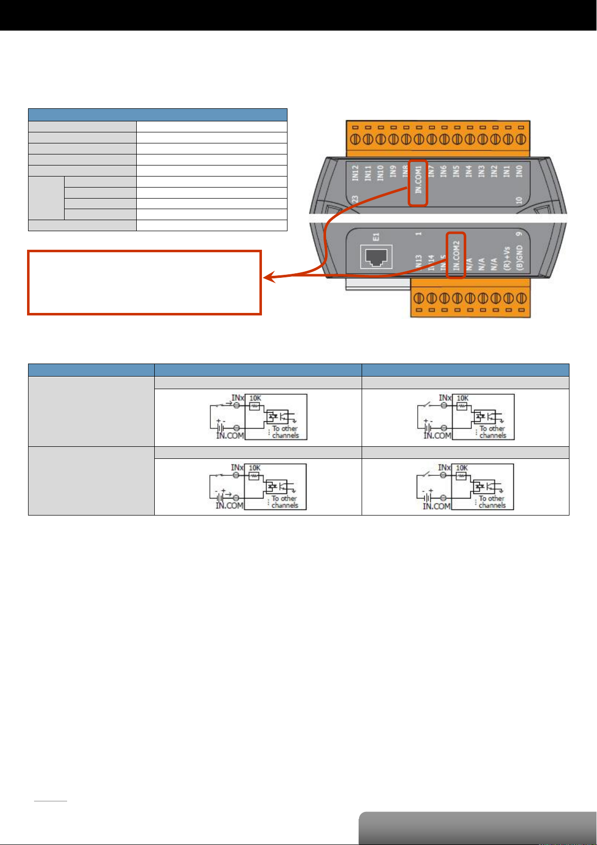
P. 52
OME-ET-7051/OME-PET-7051
| OME-ET-7000/OME-PET-7000 Series
Digital Input/Counter
Input Channels
16
Type
Wet Contact (Sink, Source)
On Voltage Level
+10 VDC ~ +50VDC
Off Voltage Level
+4 VDC max.
Input Impedance
10 KΩ
Counter
Channels
16
Max. Count
4,294,967,285 (32-bit)
Max. Input Frequency
500 Hz
Min. Pulse Width
1 ms
Overvoltage Protection
70 VDC
Digital Input/Counter
Readback as 1
Readback as 0
Sink
+10 ~ +50 VDC
Open or <4 VDC
Source
+10 ~ +50 VDC
Open or <4 VDC
The IN.COM1 and IN.COM2 of the
OME-ET-7051 are internally wired together.
But in the OME-PET-7051, they are separate.
OME-ET-7051/OME-PET-7051
I/O Specifications
Wire Connection
Pin Assignments
Page 56
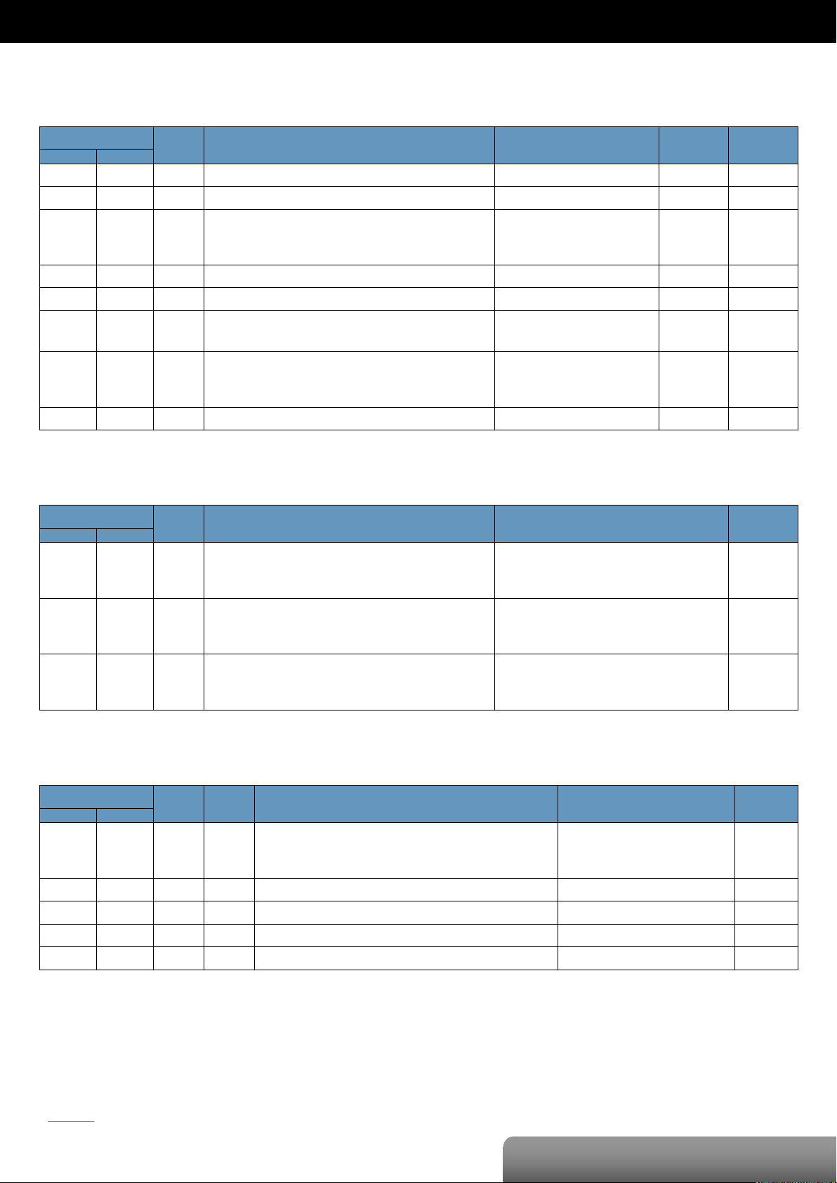
P. 53
OME-ET-7051/OME-PET-7051
| OME-ET-7000/OME-PET-7000 Series
Register
Points
Description
Data Format
Attribute
Factory Value
DEC
HEX
00032
0020
1
Clear 1-ch historical DI max. value
1: Clear W -
00033
0021
1
Clear 1-ch historical DI min. value
1: Clear W -
00034
:
00049
0022
:
0031
16
Clear the DI counter value
1: Clear W -
00126
007E
1
Reset the I/O settings to the factory default state
1: Reset W -
00133
0085
1
Reboot the module
1: Reboot W -
00150
0096
1
Enable/Disable the DI latch function
0: Disable
1: Enable
R/W/E
0
00151
:
00166
0097
:
00A6
16
Enable/Disable the DI counter function
0: Disable
1: Enable
R/W/E
0
00318
013E
1
Save preset values for the DI counter to the EEPROM
1: Save
W/E
-
Register
Points
Description
Data Format
Attribute
DEC
HEX
10000
:
10015
0000
:
000F
16
DI value
0: Off
1: On
R
10032
:
10047
0020
:
002F
16
Read DI “high latch” status
0: Normal
1: Latched
R
10064
:
10079
0040
:
004F
16
Read DI “low latch” status
0: Normal
1: Latched
R
Register
Points
No. Per
Point
Description
Data Format
Attribute
DEC
HEX
30016
:
30047
0010
:
002F
16 2 DI counter value
0 to 4294967295
R
30100
0064 1 1
Number of the DI channel
16
R
30150
0096 1 1
OS image version
0x123 means version 1.2.3
R
30151
0097 1 1
Firmware version
0x123 means version 1.2.3
R
30153
0099 1 1
I/O version
0x123 means version 1.2.3
R
Modbus Register Table
Coils (0xxxx)
Discrete Inputs (1xxxx)
Input Register (3xxxx)
Page 57

P. 54
OME-ET-7051/OME-PET-7051
| OME-ET-7000/OME-PET-7000 Series
Register
Points
No. Per
Point
Description
Data Format
Attribute
Factory Value
DEC
HEX
40050
:
40081
0032
:
0051
16
2
Set a preset value for the DI Counter
Any values updated based on the Modbus
communication will not take immediate effect
and not be saved to EEPROM until the register
(00318) is changed by a write operation.
0 to 4294967295
R/W
0
40255
00FF 1 1
Read the module reset status
1: Power-on
2: Module Watchdog
3: Software Reset Command
R
-
40256
0100 1 1
Read the boot count of the module
The factory default value is 0 when the
settings are set to the factory default values.
1 to 32767 R -
40257
0101 1 1
Set the Host WDT timeout (unit: second)
0: Disable the Host WDT
5 to 65535: Enable the Host WDT
R/W/E
0
40258
0102 1 1
Read the WDT event count
The initial value is 0 when the module is reset,
and is increased when the WDT even happens.
0 to 32767 R -
40260
0104 1 1
Read the module name
0x7051 R -
40271
010F 1 1
Set the module identification (Modbus NetID)
1 to 255
R/W/E
1
Holding Register (4xxxx)
Page 58
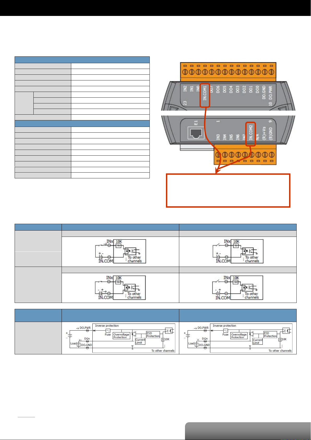
P. 55
OME-ET-7052/OME-PET-7052
| OME-ET-7000/OME-PET-7000 Series
Digital Input/Counter
Input Channels
8
Type
Wet Contact (Sink, Source)
On Voltage Level
+10 VDC ~ +50VDC
Off Voltage Level
+4 VDC max.
Input Impedance
10 KΩ
Counter
Channels
8
Max. Count
4,294,967,285 (32-bit)
Max. Input Frequency
500 Hz
Min. Pulse Width
1 ms
Overvoltage Protection
70 VDC
Digital Output
Output Channels
8
Type
Open Collector (Source)
Max. Load Current
650 mA/Channel at 25°C
Load Voltage
+10 VDC ~ +40 VDC
Overvoltage Protection
47 VDC
Overload Protection
-
Short-circuit Protection
Yes
Power-on Value
Yes, Programmable
Safe Value
Yes, Programmable
Digital Input/Counter
Readback as 1
Readback as 0
Sink
+10 ~ +50 VDC
Open or <4 VDC
Source
+10 ~ +50 VDC
Open or <4 VDC
Digital Output
ON State
Readback as 1
OFF State
Readback as 0
Source
The IN.COM1 and IN.COM2 of the OME-ET-7052
are internally wired together.
But in the OME-PET-7052, they are separate.
OME-ET-7052/OME-PET-7052
I/O Specifications
Wire Connection
Pin Assignments
Page 59
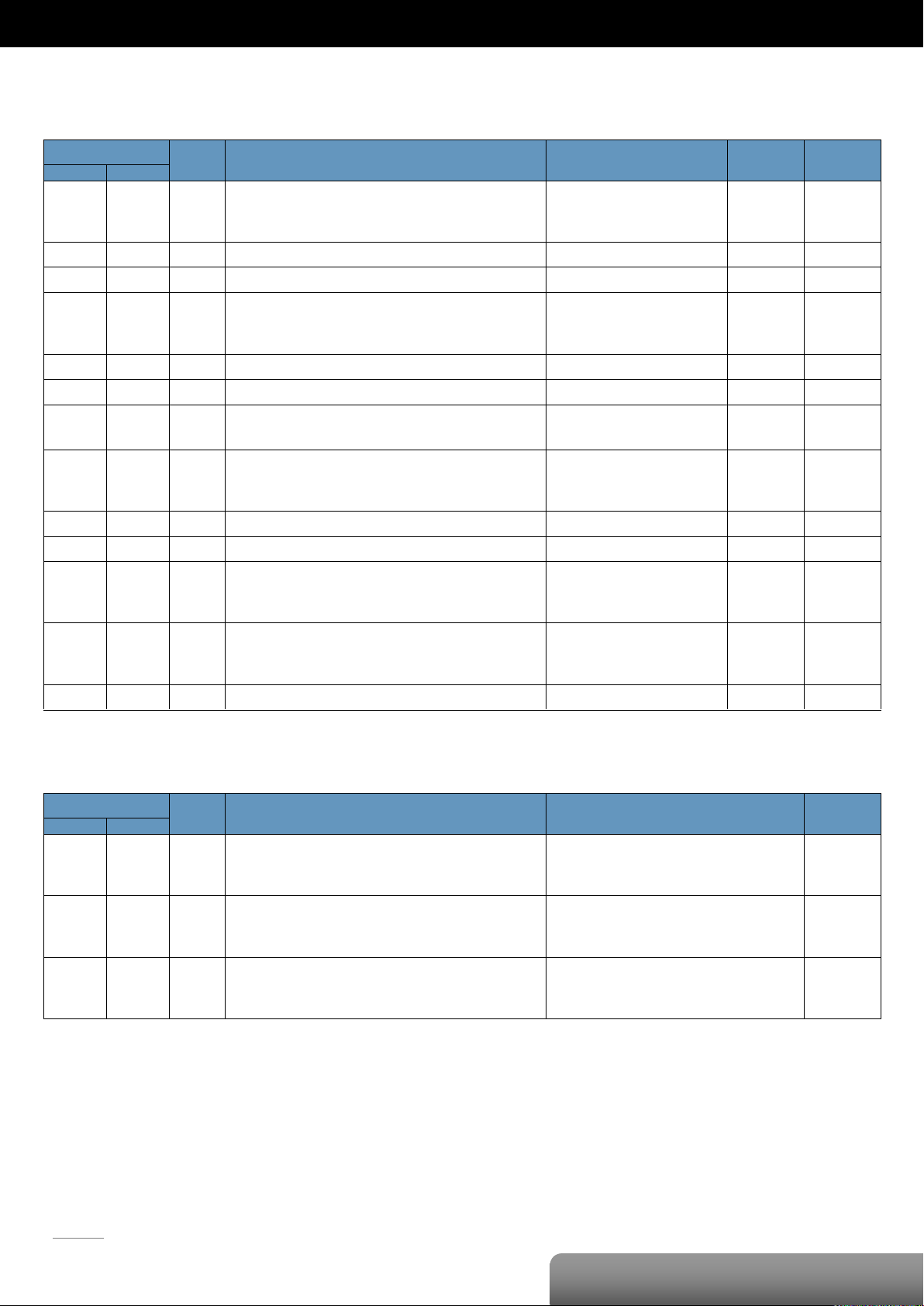
P. 56
OME-ET-7052/OME-PET-7052
| OME-ET-7000/OME-PET-7000 Series
Register
Points
Description
Data Format
Attribute
Factory Value
DEC
HEX
00000
:
00007
0000
:
0007
8
DO value
0: Off
1: On
R/W
-
00032
0020
1
Clear 1-ch historical DI max. value
1: Clear W -
00033
0021
1
Clear 1-ch historical DI min. value
1: Clear W -
00034
:
00041
0022
:
0029
8
Clear the DI counter value
1: Clear W -
00126
007E
1
Reset the I/O settings to the factory default state
1: Reset W -
00133
0085
1
Reboot the module
1: Reboot W -
00150
0096
1
Enable/Disable the DI latch function
0: Disable
1: Enable
R/W/E
0
00151
:
00158
0097
:
009E
8
Enable/Disable the DI counter function
0: Disable
1: Enable
R/W/E
0
00231
00E7
1
Save the DO power-on value to the EEPROM
1: Save
W/E
-
00232
00E8
1
Save the DO safe value to the EEPROM
1: Save
W/E
-
00235
:
00242
00EB
:
00F2
8
Enable/Disable the DO power-on value function
0: Disable
1: Enable
R/W
0
00267
:
00274
010B
:
0112
8
Enable/Disable the DO safe value function
0: Disable
1: Enable
R/W
0
00318
013E
1
Save preset values for the DI counter to the EEPROM
1: Save
W/E
-
Register
Points
Description
Data Format
Attribute
DEC
HEX
10000
:
10007
0000
:
0007
8
DI value
0: Off
1: On
R
10032
:
10039
0020
:
0027
8
Read DI “high latch” status
0: Normal
1: Latched
R
10064
:
10071
0040
:
0047
8
Read DI “low latch” status
0: Normal
1: Latched
R
Modbus Register Table
Coils (0xxxx)
Discrete Inputs (1xxxx)
Page 60
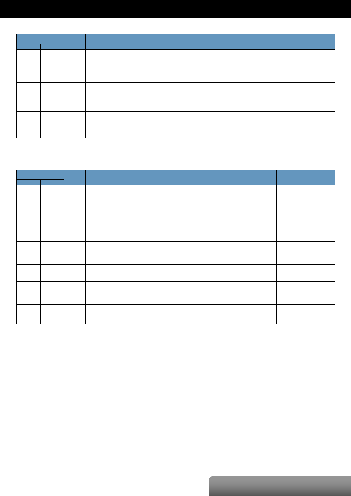
P. 57
OME-ET-7052/OME-PET-7052
| OME-ET-7000/OME-PET-7000 Series
Register
Points
No. Per
Point
Description
Data Format
Attribute
DEC
HEX
30016
:
30031
0010
:
001F
8 2 DI counter value
0 to 4294967295
R
30100
0064 1 1
Number of the DI channel
8
R
30110
006E 1 1
Number of the DO channel
8 R 30150
0096 1 1
OS image version
0x123 means version 1.2.3
R
30151
0097 1 1
Firmware version
0x123 means version 1.2.3
R
30153
0099 1 1
I/O version
0x123 means version 1.2.3
R
30160
00A0 1 1
Communication state of the pair-connection
0: Normal
<0: Failed
R
Register
Points
No. Per
Point
Description
Data Format
Attribute
Factory Value
DEC
HEX
40050
:
40065
0032
:
0041
8
2
Set a preset value for the DI Counter
Any values updated based on the Modbus
communication will not take immediate effect
and not be saved to EEPROM until the register
(00318) is changed by a write operation.
0 to 4294967295
R/W
0
40255
00FF 1 1
Read the module reset status
1: Power-on
2: Module Watchdog
3: Software Reset Command
R
-
40256
0100 1 1
Read the boot count of the module
The factory default value is 0 when the
settings are set to the factory default values.
1 to 32767 R -
40257
0101 1 1
Set the Host WDT timeout (unit: second)
0: Disable the Host WDT
5 to 65535: Enable the Host WDT
R/W/E
0
40258
0102 1 1
Read the WDT event count
The initial value is 0 when the module is reset,
and is increased when the WDT even happens.
0 to 32767 R -
40260
0104 1 1
Read the module name
0x7052 R -
40271
010F 1 1
Set the module identification (Modbus NetID)
1 to 255
R/W/E
1
Input Register (3xxxx)
Holding Register (4xxxx)
Page 61
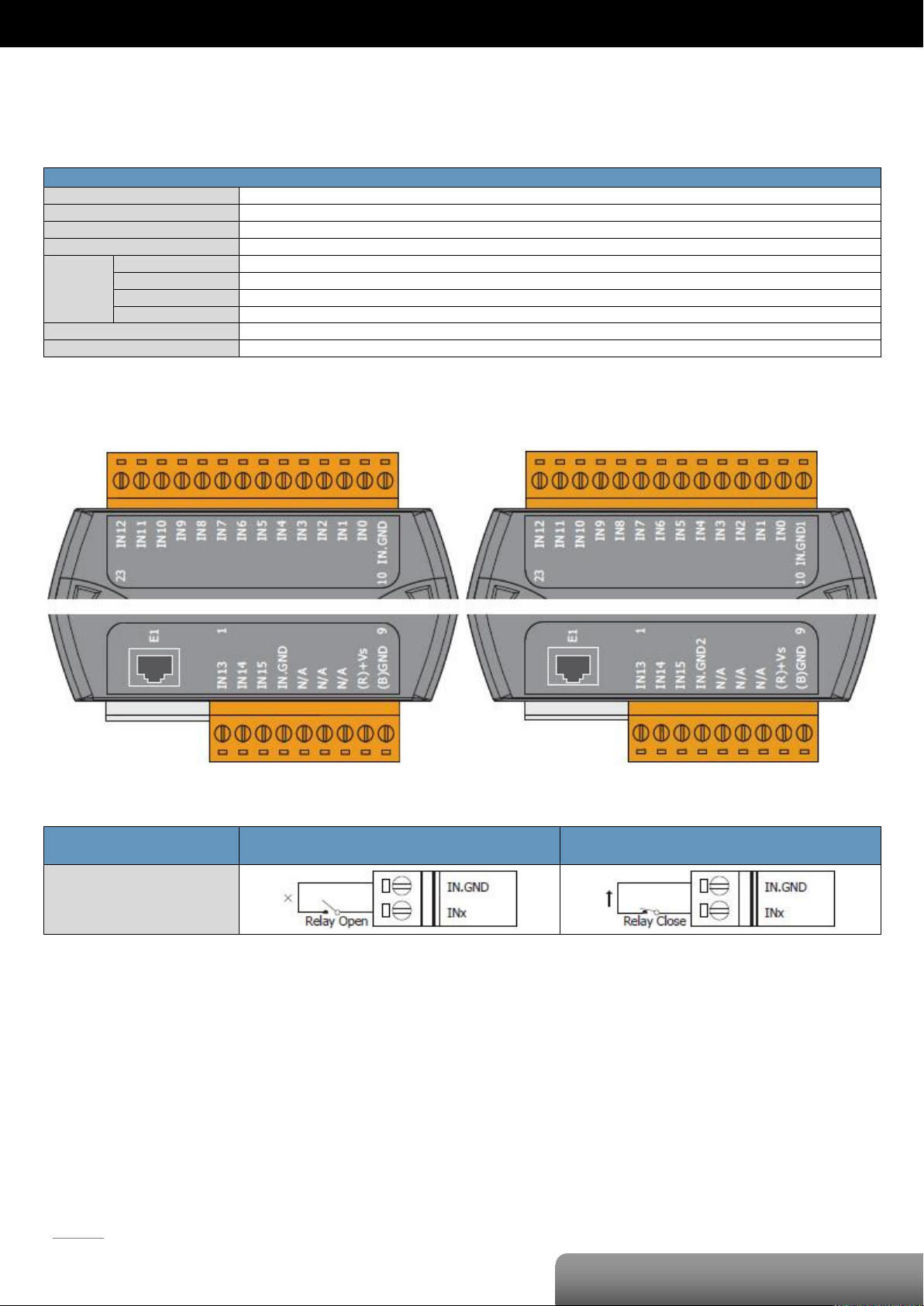
P. 58
OME-ET-7053/OME-PET-7053
| OME-ET-7000/OME-PET-7000 Series
Digital Input/Counter
Input Channels
16
Type
Dry Contact (Source)
On Voltage Level
Open
Off Voltage Level
Close to GND
Counter
Channels
16
Max. Count
4,294,967,285 (32-bit)
Max. Input Frequency
500 Hz
Min. Pulse Width
1 ms
Overvoltage Protection
-
Effective Distance
500 M max.
OME-ET-7053
OME-PET-7053
Digital Input/Counter
ON State
Readback as 1
OFF State
Readback as 0
Dry Contact
OME-ET-7053/OME-PET-7053
I/O Specifications
Pin Assignments
Wire Connection
Page 62
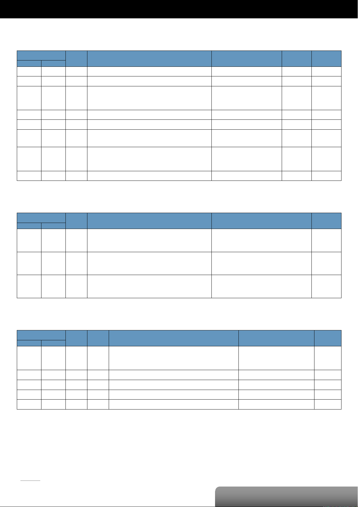
P. 59
OME-ET-7053/OME-PET-7053
| OME-ET-7000/OME-PET-7000 Series
Register
Points
Description
Data Format
Attribute
Factory Value
DEC
HEX
00032
0020
1
Clear 1-ch historical DI max. value
1: Clear W -
00033
0021
1
Clear 1-ch historical DI min. value
1: Clear W -
00034
:
00049
0022
:
0031
16
Clear the DI counter value
1: Clear W -
00126
007E
1
Reset the I/O settings to the factory default state
1: Reset W -
00133
0085
1
Reboot the module
1: Reboot W -
00150
0096
1
Enable/Disable the DI latch function
0: Disable
1: Enable
R/W/E
0
00151
:
00166
0097
:
00A6
16
Enable/Disable the DI counter function
0: Disable
1: Enable
R/W/E
0
00318
013E
1
Save preset values for the DI counter to the EEPROM
1: Save
W/E
-
Register
Points
Description
Data Format
Attribute
DEC
HEX
10000
:
10015
0000
:
000F
16
DI value
0: Off
1: On
R
10032
:
10047
0020
:
002F
16
Read DI “high latch” status
0: Normal
1: Latched
R
10064
:
10079
0040
:
004F
16
Read DI “low latch” status
0: Normal
1: Latched
R
Register
Points
No. Per
Point
Description
Data Format
Attribute
DEC
HEX
30016
:
30047
0010
:
002F
16 2 DI counter value
0 to 4294967295
R
30100
0064 1 1
Number of the DI channel
16
R
30150
0096 1 1
OS image version
0x123 means version 1.2.3
R
30151
0097 1 1
Firmware version
0x123 means version 1.2.3
R
30153
0099 1 1
I/O version
0x123 means version 1.2.3
R
Modbus Register Table
Coils (0xxxx)
Discrete Inputs (1xxxx)
Input Register (3xxxx)
Page 63
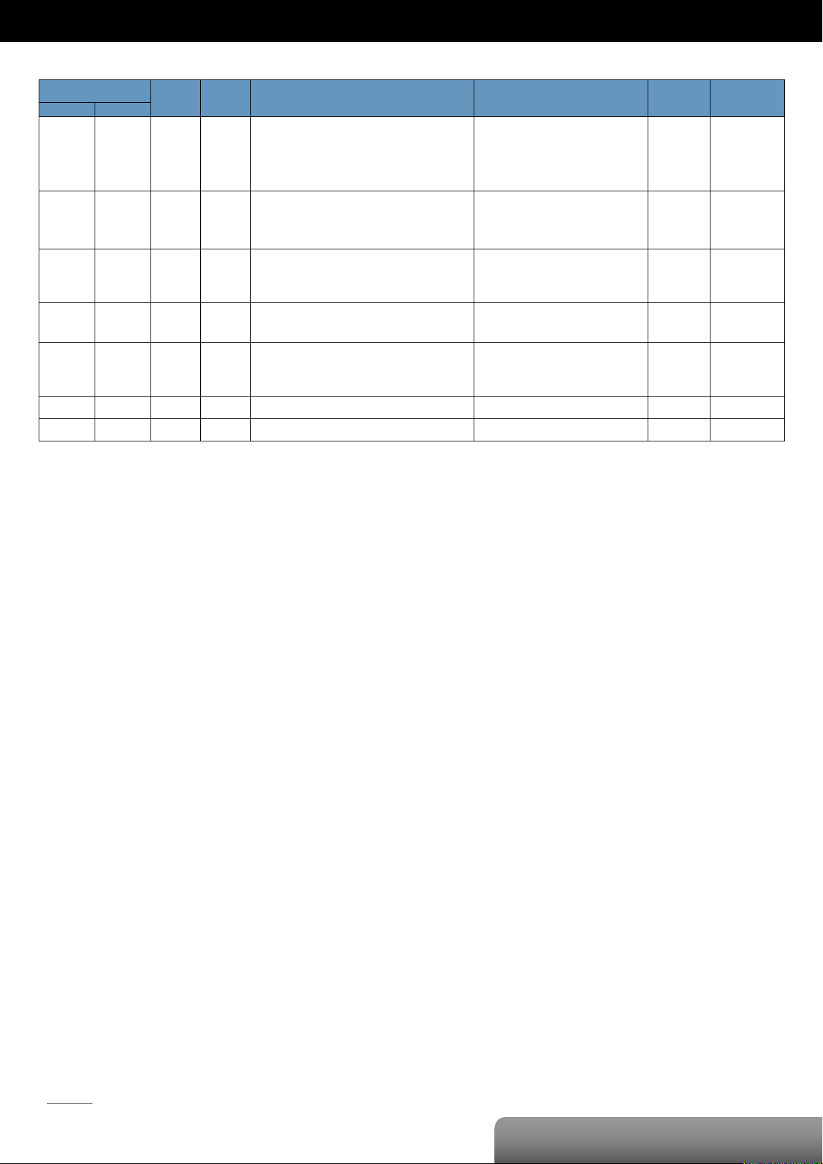
P. 60
OME-ET-7053/OME-PET-7053
| OME-ET-7000/OME-PET-7000 Series
Register
Points
No. Per
Point
Description
Data Format
Attribute
Factory Value
DEC
HEX
40050
:
40081
0032
:
0051
16
2
Set a preset value for the DI Counter
Any values updated based on the Modbus
communication will not take immediate effect
and not be saved to EEPROM until the register
(00318) is changed by a write operation.
0 to 4294967295
R/W
0
40255
00FF 1 1
Read the module reset status
1: Power-on
2: Module Watchdog
3: Software Reset Command
R
-
40256
0100 1 1
Read the boot count of the module
The factory default value is 0 when the
settings are set to the factory default values.
1 to 32767 R -
40257
0101 1 1
Set the Host WDT timeout (unit: second)
0: Disable the Host WDT
5 to 65535: Enable the Host WDT
R/W/E
0
40258
0102 1 1
Read the WDT event count
The initial value is 0 when the module is reset,
and is increased when the WDT even happens.
0 to 32767 R -
40260
0104 1 1
Read the module name
0x7053 R -
40271
010F 1 1
Set the module identification (Modbus NetID)
1 to 255
R/W/E
1
Holding Register (4xxxx)
Page 64
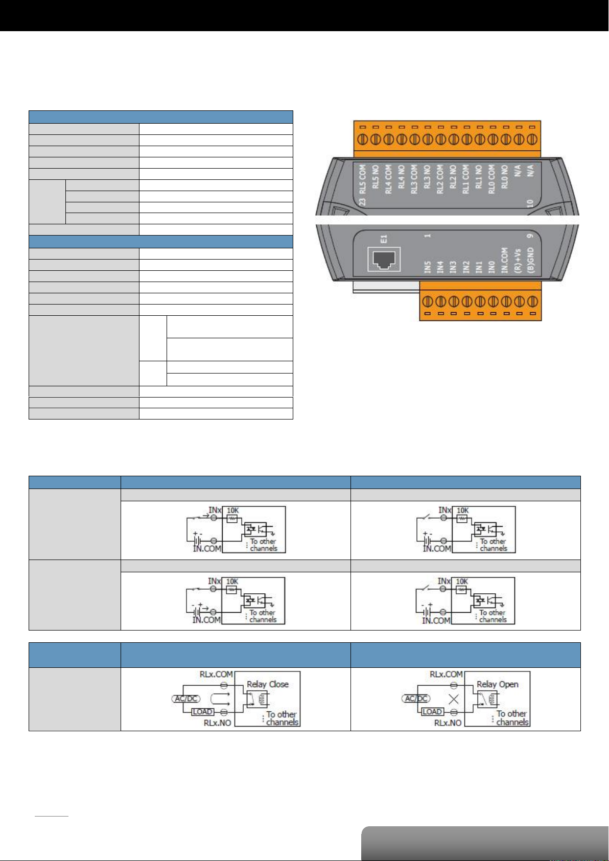
P. 61
OME-ET-7060/OME-PET-7060
| OME-ET-7000/OME-PET-7000 Series
Digital Input/Counter
Input Channels
6
Type
Wet Contact (Sink, Source)
On Voltage Level
+10 VDC ~ +50VDC
Off Voltage Level
+4 VDC max.
Input Impedance
10 KΩ
Counter
Channels
6
Max. Count
4,294,967,285 (32-bit)
Max. Input Frequency
500 Hz
Min. Pulse Width
1 ms
Overvoltage Protection
70 VDC
Power Relay
Output Channels
6
Type
Power Relay, Form A (SPST N.O.)
Operating Voltage Range
250 VAC/30VDC
Max. Load Current
5.0 A/channel at 25°C
Operate Time
6 ms (Typical)
Release Time
3 ms (Typical)
Electrical Life (Resistive Load)
VDE:
5A @ 250 VAC 30,000 ops
(10 ops/minute) at 75°C
5A @ 30 VAC 70,000 ops
(10 ops/minute) at 75°C
UL:
5A @ 250 VAC/30 VDC 6,000 ops
3A @ 250 VAC/30 VDC 100,000 ops
Mechanical Life
20,000,000 ops. at no load (300 ops/minute)
Power-on Value
Yes, Programmable
Safe Value
Yes, Programmable
Digital Input/Counter
Readback as 1
Readback as 0
Sink
+10 ~ +50 VDC
Open or <4 VDC
Source
+10 ~ +50 VDC
Open or <4 VDC
Power Relay
ON State
Readback as 1
OFF State
Readback as 0
Relay Output
OME-ET-7060/OME-PET-7060
I/O Specifications
Wire Connection
Pin Assignments
Page 65
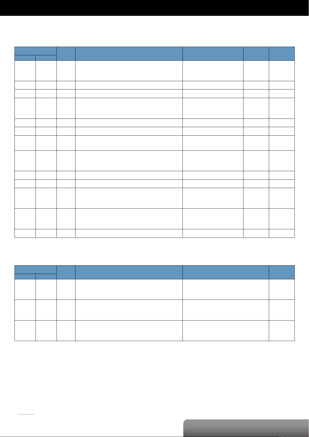
P. 62
OME-ET-7060/OME-PET-7060
| OME-ET-7000/OME-PET-7000 Series
Register
Points
Description
Data Format
Attribute
Factory Value
DEC
HEX
00000
:
00005
0000
:
0005
6
DO value
0: Off
1: On
R/W
-
00032
0020
1
Clear 1-ch historical DI max. value
1: Clear W -
00033
0021
1
Clear 1-ch historical DI min. value
1: Clear W -
00034
:
00039
0022
:
0027
6
Clear the DI counter value
1: Clear W -
00126
007E
1
Reset the I/O settings to the factory default state
1: Reset W -
00133
0085
1
Reboot the module
1: Reboot W -
00150
0096
1
Enable/Disable the DI latch function
0: Disable
1: Enable
R/W/E
0
00151
:
00156
0097
:
009C
6
Enable/Disable the DI counter function
0: Disable
1: Enable
R/W/E
0
00231
00E7
1
Save the DO power-on value to the EEPROM
1: Save
W/E
-
00232
00E8
1
Save the DO safe value to the EEPROM
1: Save
W/E
-
00235
:
00240
00EB
:
00F0
6
Enable/Disable the DO power-on value function
0: Disable
1: Enable
R/W
0
00267
:
00272
010B
:
0110
6
Enable/Disable the DO safe value function
0: Disable
1: Enable
R/W
0
00318
013E
1
Save preset values for the DI counter to the EEPROM
1: Save
W/E
-
Register
Points
Description
Data Format
Attribute
DEC
HEX
10000
:
10005
0000
:
0005
6
DI value
0: Off
1: On
R
10032
:
10037
0020
:
0025
6
Read DI “high latch” status
0: Normal
1: Latched
R
10064
:
10069
0040
:
0045
6
Read DI “low latch” status
0: Normal
1: Latched
R
Modbus Register Table
Coils (0xxxx)
Discrete Inputs (1xxxx)
Page 66
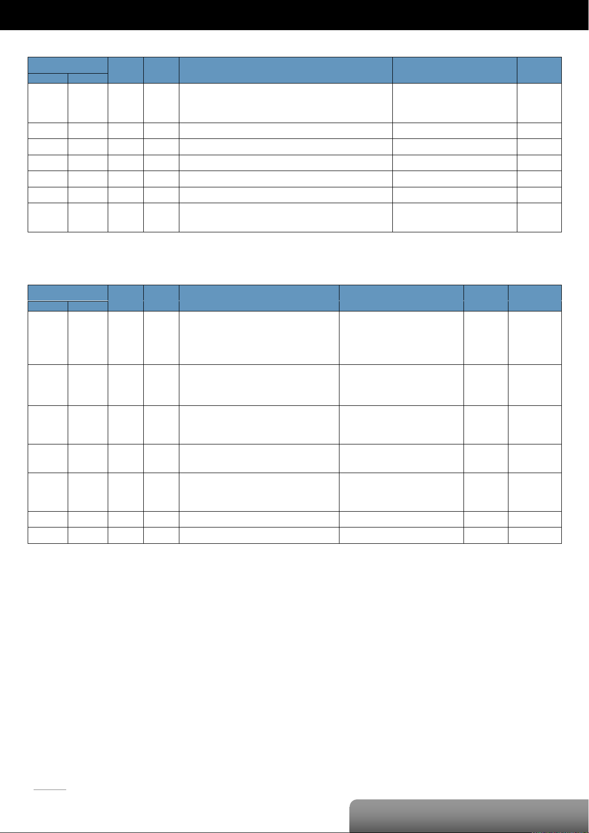
P. 63
OME-ET-7060/OME-PET-7060
| OME-ET-7000/OME-PET-7000 Series
Register
Points
No. Per
Point
Description
Data Format
Attribute
DEC
HEX
30016
:
30027
0010
:
001B
6 2 DI counter value
0 to 4294967295
R
30100
0064 1 1
Number of the DI channel
6
R
30110
006E 1 1
Number of the DO channel
6 R 30150
0096 1 1
OS image version
0x123 means version 1.2.3
R
30151
0097 1 1
Firmware version
0x123 means version 1.2.3
R
30153
0099 1 1
I/O version
0x123 means version 1.2.3
R
30160
00A0 1 1
Communication state of the pair-connection
0: Normal
<0: Failed
R
Register
Points
No. Per
Point
Description
Data Format
Attribute
Factory Value
DEC
HEX
40050
:
40061
0032
:
003D
6
2
Set a preset value for the DI Counter
Any values updated based on the Modbus
communication will not take immediate effect
and not be saved to EEPROM until the register
(00318) is changed by a write operation.
0 to 4294967295
R/W
0
40255
00FF 1 1
Read the module reset status
1: Power-on
2: Module Watchdog
3: Software Reset Command
R
-
40256
0100 1 1
Read the boot count of the module
The factory default value is 0 when the
settings are set to the factory default values.
1 to 32767 R -
40257
0101 1 1
Set the Host WDT timeout (unit: second)
0: Disable the Host WDT
5 to 65535: Enable the Host WDT
R/W/E
0
40258
0102 1 1
Read the WDT event count
The initial value is 0 when the module is reset,
and is increased when the WDT even happens.
0 to 32767 R -
40260
0104 1 1
Read the module name
0x7060 R -
40271
010F 1 1
Set the module identification (Modbus NetID)
1 to 255
R/W/E
1
Input Register (3xxxx)
Holding Register (4xxxx)
Page 67
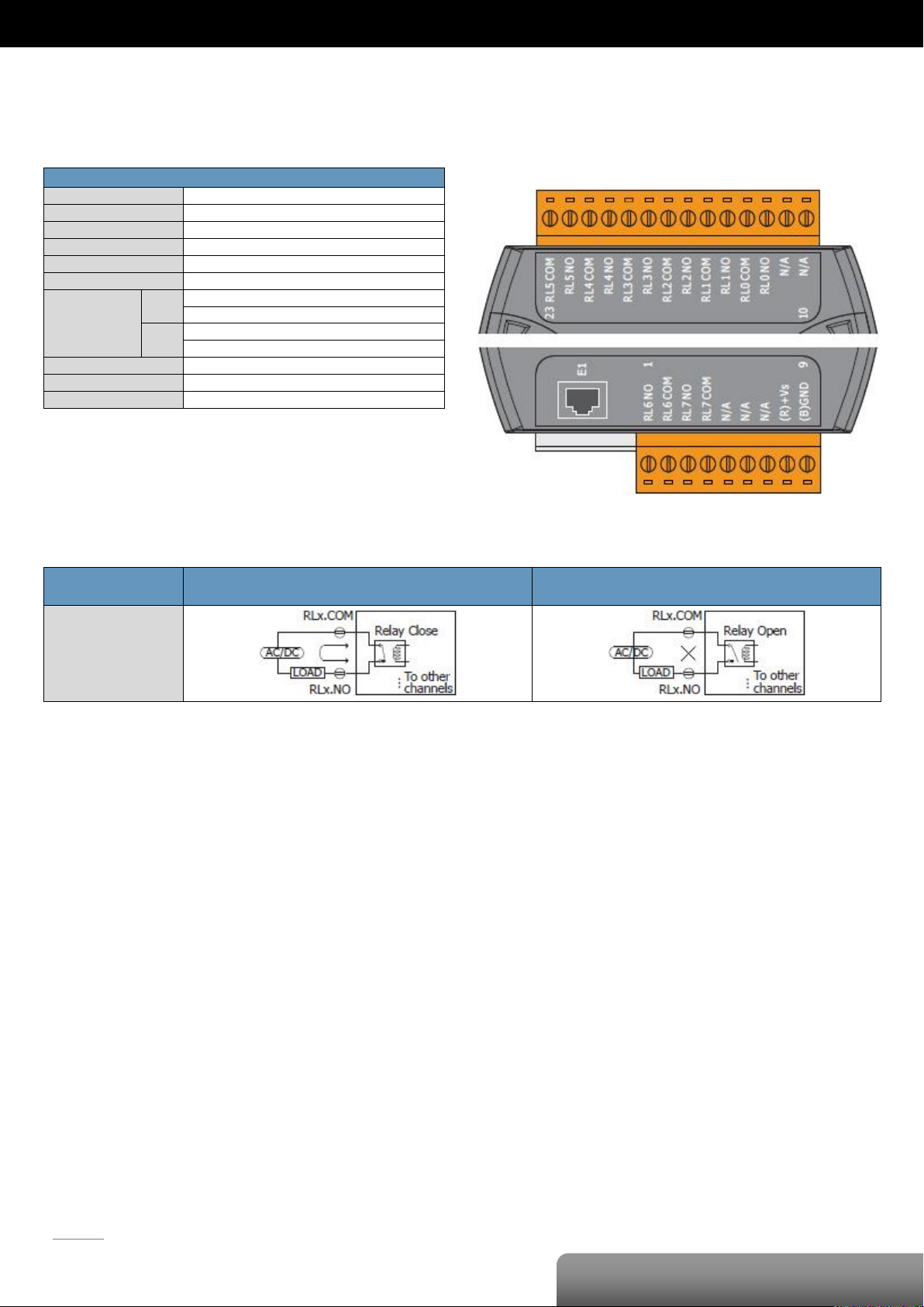
P. 64
OME-ET-7067/OME-PET-7067
| OME-ET-7000/OME-PET-7000 Series
PhotoMOS Relay
Output Channels
8
Type
Power Relay, Form A (SPST N.O.)
Operating Voltage Range
250 VAC/30 VDC
Max. Load Current
5.0 A/Channel at 25°C
Operate Time
6 ms (Typical)
Release Time
3 ms (Typical)
Electrical Life
(Resistive Load)
VDE
5A @ 250 VAC 30,000 ops (10 ops/minute) at 75°C
5A @ 30 VAC 70,000 ops (10 ops/minute) at 75°C
UL
5A @ 250 VAC/30 VDC 6,000 ops
3A @ 250 VAC/30 VDC 100,000 ops
Mechanical Life
20,000,000 ops. at no load (300 ops/minute)
Power-on Value
Yes, Programmable
Safe Value
Yes, Programmable
Power Relay
ON State
Readback as 1
OFF State
Readback as 0
Relay Output
OME-ET-7067/OME-PET-7067
I/O Specifications
Wire Connection
Pin Assignments
Page 68
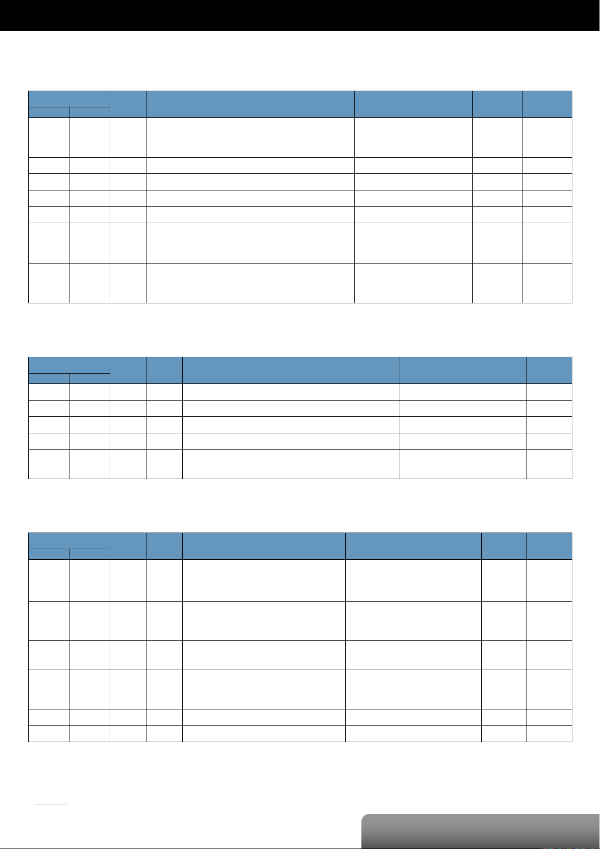
P. 65
OME-ET-7067/OME-PET-7067
| OME-ET-7000/OME-PET-7000 Series
Register
Points
Description
Data Format
Attribute
Factory Value
DEC
HEX
00000
:
00007
0000
:
0007
8
DO value
0: Off
1: On
R/W
-
00126
007E
1
Reset the I/O settings to the factory default state
1: Reset W -
00133
0085
1
Reboot the module
1: Reboot W -
00231
00E7
1
Save the DO power-on value to the EEPROM
1: Save
W/E
-
00232
00E8
1
Save the DO safe value to the EEPROM
1: Save
W/E
-
00235
:
00242
00EB
:
00F2
8
Enable/Disable the DO power-on value function
0: Disable
1: Enable
R/W
0
00267
:
00274
010B
:
0112
8
Enable/Disable the DO safe value function
0: Disable
1: Enable
R/W
0
Register
Points
No. Per
Point
Description
Data Format
Attribute
DEC
HEX
30110
006E 1 1
Number of the DO channel
8
R
30150
0096 1 1
OS image version
0x123 means version 1.2.3
R
30151
0097 1 1
Firmware version
0x123 means version 1.2.3
R
30153
0099 1 1
I/O version
0x123 means version 1.2.3
R
30160
00A0 1 1
Communication state of the pair-connection
0: Normal
<0: Failed
R
Register
Points
No. Per
Point
Description
Data Format
Attribute
Factory Value
DEC
HEX
40255
00FF 1 1
Read the module reset status
1: Power-on
2: Module Watchdog
3: Software Reset Command
R
-
40256
0100 1 1
Read the boot count of the module
The factory default value is 0 when the
settings are set to the factory default values.
1 to 32767
R
-
40257
0101 1 1
Set the Host WDT timeout (unit: second)
0: Disable the Host WDT
5 to 65535: Enable the Host WDT
R/W/E
0
40258
0102 1 1
Read the WDT event count
The initial value is 0 when the module is reset,
and is increased when the WDT even happens.
0 to 32767
R
-
40260
0104 1 1
Read the module name
0x7067 R -
40271
010F 1 1
Set the module identification (Modbus NetID)
1 to 255
R/W/E
1
Modbus Register Table
Coils (0xxxx)
Input Register (3xxxx)
Holding Register (4xxxx)
Page 69
P. 66
| OME-ET-7000/OME-PET-7000 Series
Type Code
Input Range
Data Format
+F.S
-F.S
00
-15 ~ +15 mV
Engineering Unit
+15000
-15000
2’s comp HEX
7FFF
8000
01
-50 ~ +50 mV
Engineering Unit
+5000
-5000
2’s comp HEX
7FFF
8000
02
-100 ~ +100 mV
Engineering Unit
+10000
-10000
2’s comp HEX
7FFF
8000
03
-500 ~ +500 mV
Engineering Unit
+5000
-5000
2’s comp HEX
7FFF
8000
04
-1 ~ +1 V
Engineering Unit
+10000
-10000
2’s comp HEX
7FFF
8000
05
-2.5 ~ +2.5 V
Engineering Unit
+25000
-25000
2’s comp HEX
7FFF
8000
06
-20 ~ +20 mA
Engineering Unit
+20000
-20000
2’s comp HEX
7FFF
8000
07
+4 ~ +20 mA
Engineering Unit
+20000
+4000
2’s comp HEX
FFFF
0000
08
-10 ~ +10 V
Engineering Unit
+10000
-10000
2’s comp HEX
7FFF
8000
09
-5 ~ +5 V
Engineering Unit
+5000
-5000
2’s comp HEX
7FFF
8000
0A
-1 ~ +1 V
Engineering Unit
+10000
-10000
2’s comp HEX
7FFF
8000
0B
-500 ~ +500 mV
Engineering Unit
+5000
-5000
2’s comp HEX
7FFF
8000
0C
-150 ~ +150 mV
Engineering Unit
+15000
-15000
2’s comp HEX
7FFF
8000
0D
-20 ~ +20 mA
Engineering Unit
+20000
-20000
2’s comp HEX
7FFF
8000
1A
0 ~ +20 mA
Engineering Unit
+20000
0
2’s comp HEX
FFFF
0000
0E
Type J
Thermocouple -210 ~ 760°C
Engineering Unit
+7600
-2100
2’s comp HEX
7FFF
DCA2
0F
Type K
Thermocouple -270 ~ 1372°C
Engineering Unit
+13720
-2700
2’s comp HEX
7FFF
E6D0
10
Type T
Thermocouple -270 ~ 400°C
Engineering Unit
+4000
-2700
2’s comp HEX
7FFF
A99A
11
Type E
Thermocouple -270 ~ 1000°C
Engineering Unit
10000
-2700
2’s comp HEX
7FFF
DD71
12
Type R
Thermocouple 0 ~ 1768°C
Engineering Unit
+17680
0
2’s comp HEX
7FFF
0000
13
Type S
Thermocouple 0 ~ 1768°C
Engineering Unit
+17680
0
2’s comp HEX
7FFF
0000
14
Type B
Thermocouple 0 ~ 1820°C
Engineering Unit
+18200
0
2’s comp HEX
7FFF
0000
15
Type N
Thermocouple -270 ~ 1300°C
Engineering Unit
+13000
-2700
2’s comp HEX
7FFF
E56B
16
Type C
Thermocouple 0 ~ 2320°C
Engineering Unit
+23200
0
2’s comp HEX
7FFF
0000
17
Type L
Thermocouple -200 ~ 800°C
Engineering Unit
+8000
-2000
2’s comp HEX
7FFF
E000
18
Type M
Engineering Unit
+10000
-20000
Appendix
A. Analog Input Type and Data Format Table
Page 70

P. 67
| OME-ET-7000/OME-PET-7000 Series
Thermocouple -200 ~ 100°C
2’s comp HEX
4000
8000
19
Type L DIN43710
Thermocouple -200 ~ 900°C
Engineering Unit
9000
-2000
2’s comp HEX
FFFF
E38E
20
Platinum 100, α=0.00385
-100 ~ 100°C
Engineering Unit
+10000
-10000
2’s comp HEX
7FFF
8000
21
Platinum 100, α=0.00385
0 ~ 100°C
Engineering Unit
+10000
0
2’s comp HEX
7FFF
0000
22
Platinum 100, α=0.00385
0 ~ 200°C
Engineering Unit
+20000
0
2’s comp HEX
7FFF
0000
23
Platinum 100, α=0.00385
0 ~ 600°C
Engineering Unit
+6000
0
2’s comp HEX
7FFF
0000
24
Platinum 100, α=0.003916
-100 ~ 100°C
Engineering Unit
+10000
-10000
2’s comp HEX
7FFF
8000
25
Platinum 100, α=0.003916
0 ~ 100°C
Engineering Unit
+10000
0
2’s comp HEX
7FFF
0000
26
Platinum 100, α=0.003916
0 ~ 200°C
Engineering Unit
+20000
0
2’s comp HEX
7FFF
0000
27
Platinum 100, α=0.003916
0 ~ 600°C
Engineering Unit
+6000
0
2’s comp HEX
7FFF
0000
28
Nickel 120,
-80 ~ 100°C
Engineering Unit
+10000
-8000
2’s comp HEX
7FFF
999A
29
Nickel 120
0 ~ 100°C
Engineering Unit
+10000
0
2’s comp HEX
7FFF
0000
2A
Platinum 1000, α=0.00385
-200 ~ 600°C
Engineering Unit
+6000
-2000
2’s comp HEX
7FFF
D556
2B
Cu 100, α=0.00421
-20 ~ 150°C
Engineering Unit
+15000
-2000
2’s comp HEX
7FFF
EEEF
2C
Cu 100, α=0.00427
0 ~ 200°C
Engineering Unit
+20000
0
2’s comp HEX
7FFF
0000
2D
Cu 1000, α=0.00421
-20 ~ 150°C
Engineering Unit
+15000
-2000
2’s comp HEX
7FFF
EEEF
2E
Platinum 1000, α=0.00385
-200 ~ 200°C
Engineering Unit
+20000
-20000
2’s comp HEX
7FFF
8000
2F
Platinum 1000, α=0.003916
-200 ~ 200°C
Engineering Unit
+20000
-20000
2’s comp HEX
7FFF
8000
80
Platinum 100, α=0.00385
-200 ~ 600°C
Engineering Unit
+6000
-2000
2’s comp HEX
7FFF
D556
81
Platinum 100, α=0.003916
-200 ~ 600°C
Engineering Unit
+6000
-2000
2’s comp HEX
7FFF
D556
82
Cu 50
-50 ~ 150°C
Engineering Unit
+15000
-5000
2’s comp HEX
7FFF
D556
83
Nickel 100
-60 ~ 180°C
Engineering Unit
+18000
-6000
2’s comp HEX
7FFF
D556
Page 71

P. 68
| OME-ET-7000/OME-PET-7000 Series
Type Code
Input Range
Data Format
+F.S
-F.S
30
0 ~ +20 mV
Engineering Unit
+20000
0
2’s comp HEX
FFFF
0000
31
4 ~ +20 mV
Engineering Unit
+20000
4000
2’s comp HEX
FFFF
0000
32
0 ~ +10 V
Engineering Unit
+10000
0
2’s comp HEX
7FFF
0000
33
-10 ~ +10 V
Engineering Unit
+10000
-10000
2’s comp HEX
7FFF
8000
34
0 ~ +5 V
Engineering Unit
+5000
0
2’s comp HEX
7FFF
0000
35
-5 ~ +5 V
Engineering Unit
+5000
-5000
2’s comp HEX
7FFF
8000
B. Analog Output Type and Data Format Table
Page 72

WARRANTY/DISCLAIMER
OMEGA ENGINEERING, INC. warrants this unit to be free of defects in materials and workmanship for
a period of 13 months from date of purchase. OMEGA’s WARRANTY adds an additional one (1)
month grace period to the normal one (1) year product warranty to cover handling and shipping
time. This ensures that OMEGA’s customers receive maximum coverage on each product.
If the unit malfunctions, it must be returned to the factory for evaluation. OMEGA’s Customer Service
Department will issue an Authorized Return (AR) number immediately upon phone or written request.
Upon examination by OMEGA, if the unit is found to be defective, it will be repaired or replaced at no
charge. OMEGA’s WARRANTY does not apply to defects resulting from any action of the purchaser,
including but not limited to mishandling, improper interfacing, operation outside of design limits,
improper repair, or unauthorized modification. This WARRANTY is VOID if the unit shows evidence of
having been tampered with or shows evidence of having been damaged as a result of excessive
corrosion; or current, heat, moisture or vibration; improper specification; misapplication; misuse or
other operating conditions outside of OMEGA’s control. Components in which wear is not warranted,
include but are not limited to contact points, fuses, and triacs.
OMEGA is pleased to offer suggestions on the use of its various products. However,
OMEGA neither assumes responsibility for any omissions or errors nor assumes liability
for any damages that result from the use of its products in accordance with information
provided by OMEGA, either verbal or written. OMEGA warrants only that the parts
manufactured by the company will be as specified and free of defects. OMEGA MAKES
NO OTHER WARRANTIES OR REPRESENTATIONS OF ANY KIND WHATSOEVER,
EXPRESSED OR IMPLIED, EXCEPT THAT OF TITLE, AND ALL IMPLIED WARRANTIES
INCLUDING ANY WARRANTY OF MERCHANTABILITY AND FITNESS FOR A PARTICULAR
PURPOSE ARE HEREBY DISCLAIMED. LIMITATION OF LIABILITY: The remedies of
purchaser set forth herein are exclusive, and the total liability of OMEGA with respect to
this order, whether based on contract, warranty, negligence, indemnification, strict
liability or otherwise, shall not exceed the purchase price of the component upon which
liability is based. In no event shall OMEGA be liable for consequential, incidental or
special damages.
CONDITIONS: Equipment sold by OMEGA is not intended to be used, nor shall it be used: (1) as a
“Basic Component” under 10 CFR 21 (NRC), used in or with any nuclear installation or activity; or (2)
in medical applications or used on humans. Should any Product(s) be used in or with any nuclear
installation or activity, medical application, used on humans, or misused in any way, OMEGA
assumes no responsibility as set forth in our basic WARRANTY / DISCLAIMER language, and,
additionally, purchaser will indemnify OMEGA and hold OMEGA harmless from any liability or
damage whatsoever arising out of the use of the Product(s) in such a manner.
RETURN REQUESTS/INQUIRIES
Direct all warranty and repair requests/inquiries to the OMEGA Customer Service Department.
BEFORE RETURNING ANY PRODUCT(S) TO OMEGA, PURCHASER MUST OBTAIN AN AUTHORIZED
RETURN (AR) NUMBER FROM OMEGA’S CUSTOMER SERVICE DEPARTMENT (IN ORDER TO AVOID
PROCESSING DELAYS). The assigned AR number should then be marked on the outside of the
return package and on any correspondence.
The purchaser is responsible for shipping charges, freight, insurance and proper packaging to
prevent breakage in transit.
FOR WARRANTY
following information available BEFORE
contacting OMEGA:
1. Purchase Order number under which
the product was PURCHASED,
2. Model and serial number of the product
under warranty, and
3. Repair instructions and/or specific
problems relative to the product.
OMEGA’s policy is to make running changes, not model changes, whenever an improvement is possible.
This affords our customers the latest in technology and engineering.
OMEGA is a registered trademark of OMEGA ENGINEERING, INC.
© Copyright 2012 OMEGA ENGINEERING, INC. All rights reserved. This document may not be copied, photocopied, reproduced, translated, or reduced to any electronic medium or machine-readable form, in whole or in part, without the prior
written consent of OMEGA ENGINEERING, INC.
RETURNS, please have the
FOR NON-WARRANTY REPAIRS,
consult OMEGA
for current repair charges. Have the following
information available BEFORE contacting OMEGA:
1. Purchase Order number to cover the
COST of the repair,
2. Model and serial number of the
product, and
3. Repair instructions and/or specific problems
relative to the product.
Page 73

M5247/0113
 Loading...