

Page 1

AC Current Data Logger
1
Page 2

AC Current Data Logger
OM-DLAC DATA LOGGER INSTRUCTIONS
The OMEGA OM-DLAC Data Logger is a self-contained precision instrument for
recording AC Current using a clamp on probe. The OM-DLAC can store up to
16,000 measurements for each recording. The recordings can be read using the
supplied PC interface or the optional OM-DP3 Data Plotter.
The Windows™ compatible software allows the user to set the OM-DLAC for a
recording session, read the recorded data in text or graphical format, and to
store the recorded data for future reference or analysis. Applications include
monitoring of compressor and fan run cycles, new installation tests, trouble
shooting intermittent problems, etc. Refer to the following instructions for explanations of how to record and how to retrieve AC Current recordings.
SOFTWARE INSTALLATION
The Data Logger to PC program is suppl ied on 3-½″ floppy disks. To install the
software follow the instructions below:
1. Insert disk 1 of 2 into Drive A.
1. If you are using Window™98/95, click on START, then click on RUN.
3. Type A:SETUP and press Enter.
4. If you are using Windows™3.1, click on Program Manager.
5. Select FILE, and select RUN.
6. Type A:SETUP and press Enter.
To get the latest product information and current release of the Data Logger to
PC software visit the OMEGA website at www.omega.com
If you are not familiar with the above commands, refer to the instructions that are
supplied with your version of Windows™.
SETTING THE DATA LOGGER
The OM-DLAC recording interval or sampling rate is the time between each current measurement that is saved in the logger’s memory. This interval is set from
the PC interface program (supplied) or from the optional OM-DP3 Data Plotter.
This interval can be set from 5 seconds to 60 minutes. A user message of up to
20 characters can also be stored in the OM-DLAC. This message can be used to
identify a customer’s location or identify a particular logger for tracking purposes. Use the example below to set a OM-DLAC logger.
1. Plug the PC interface cable OM-DLS into the printer port of the computer
being used to set the OM-DLAC. Plug the OM-DLAC being set to the cable
from the PC interface cable DLCABLE (part of OM-DLS packa ge).
1. Start the Data Logger program. If you are using Windows™98/95, click on
Start, click on Programs, click on Omegalog, click on OMEGALOG. If you
2
Page 3
AC Current Data Logger
are using Windows™3.1, double-click on t he window lab e led Omegalog,
then double-click on the OMEGALOG icon.
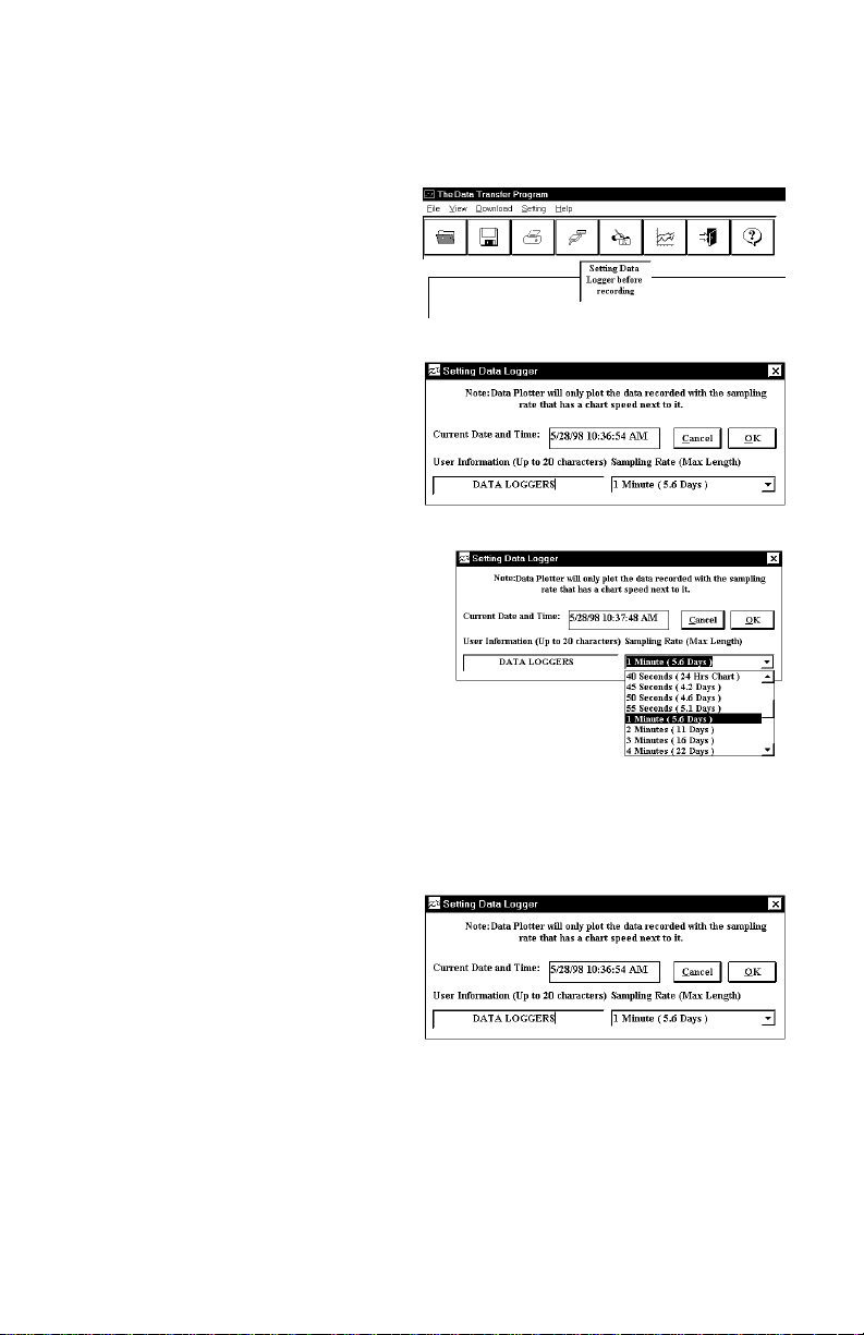
3. The program will open with a
blank window showing no text or
graph. On the toolbar located
along the top of the screen, click
on the Setting Data Logger
before recording button. This
will open a secondary window
Setting Data Logger.
4. If a user message is desired,
click in the User Information
field and add t he desired
message. Note that the last
message will be dis-played and
will remain until it is erased or
changed by the user.
5. To select the sampling rate, click on
the down arrow in the Sampling
Rate box. This will open a dropdown menu wit h the recording
interval selections. Note that the
maximum recordin g times are
indicated in parentheses next to the
recording interval. The recording
intervals that correspo nd to ch ar ts
used by the OM-DP3 Data Plotter
show the appropriate ch ar t sel e ctio n instead of a maximum recording time.
6. Click on the desired sampling rate. You may need to use the up or down
arrows on the drop down menu to see more of the available recording intervals.
7. The time and date the logger is
set to will be the same time as
the PC clock. It is important to
make sure the time set in the PC
is correct. The PC time will be
displayed as the Current Date
and Time in the setting window.
Refer to the owner’s manual for your computer to find instructions on setting
the PC time if it is not correct.
8. When all of the settings for the OM-DLAC are to your satisfaction, click on OK
to store the setting in the OM-DLAC and to close the window.
9. The OM-DLAC is now set and ready to begin a new recording. Disconnect
the OM-DLAC from the PC interface.
3
Page 4
AC Current Data Logger
10. You can now connect a different OM-DLAC or exit the program. To exit the
program, click on the Exit button on the tool bar.
TO START A RECORDING
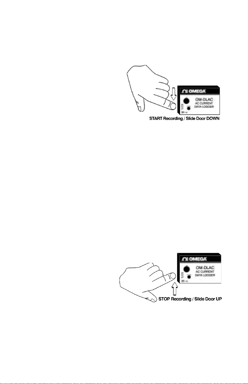
To begin a new recording, slide the
access door closed. The LED ind i ca tor
will begin to flash for 10 seconds.
During this period the recording can
be can celed w ithout losing the dat a
previ o usly re corded . When the LED
indicator stops flashing, a new
recording has begun and an y previous
data has been erased. The OM-DLAC
recording function can be “locked” on
by passing a Ty-Wrap™ or similar restriction through the logger-mounting
opening. This can be used to prevent accidental or intentional disruptions of an
AC current recording.
The LED will flash every 5 seconds to indicate operation. A bright flash of the
LED is used to indicate that the loop current has been sampled and recorded. A
dim flash is used to indicate that the OM-DLAC is operating properly and the AC
Current has not been sampled or recorded. The LED indicator will continue to
flash until the user stops the recording or the memory has reached its maximum
capacity of 16,000 samples.
NOTE: If the battery is exhausted duri ng a r eco r ding, the OM-DLAC will
automatically terminate the recording and save any data recorded up to that
point. The LED will stop flashing and the OM-DLAC will not allow a new recording to be started until the ba tter y has been replaced. Recorded data
can be retrieved regardless of the condition of the battery.
TO STOP A RECORDING
Slide the access door open (If
locked, remove the restriction
device first.) The LED indicator will
stop flashing. The recorded data
can now be retrieved using the
supplied Windows™ compatible
software and PC interface, or the
AC Current recording can be
plotted on a circular chart using the
optional OM-DP3 Data Plotter.
NOTE: Do not close the door until a new recording is desired! It is important
to leave the door open until you want to start a new recording. Starting a new
recording now will erase the previous recording. To prevent accidental erasing
of recordings, the access door of the OM-DLAC can be “locked” open by passing a Ty-Wrap™ or similar restriction through the lock opening. The AC Current
recording will remain in the OM-DLAC until a new recording is started. The recordings may be retrieved as many times as required or the battery can be re-
4
Page 5
AC Current Data Logger
moved with no effect on the stored data.
CONNECTING THE OM-DLAC
Plug each lead from the clamp on probe firmly into the OM-DLAC. Make sure
that there is no strain that could pull the leads out of the OM-DLAC socket. Place
the clamp on probe around the wire that the current is being measured. Make
sure that the probe will not interfere with any moving pieces of equipment and
will not pull loose the wire being measured. The clamp on probe and OM-DLAC
are not water resistant! Do not expose to rain or snow.
CAUTION!
Electrical connection to any type of operating
equipment is Dangerous!
The OM-DLAC probe should only be connected
when it has been determined that the power is off
and the equipment is safe to touch!
RETRIEVING AC CURRENT RECORDINGS
1. Plug the PC interface into the printer port of the computer being used to set
the OM-DLAC. Plug the OM-DLAC being read to the cable from the PC interface.
2. Start the Data Logger program. If you are using Windows™98/95 click on
Start, click on Programs, click on Omegalog, click on OMEGALOG.
3. If you are using Windows™3.11 double-click on the window labeled
Omegalog, double-click on the OMEGALOG icon.
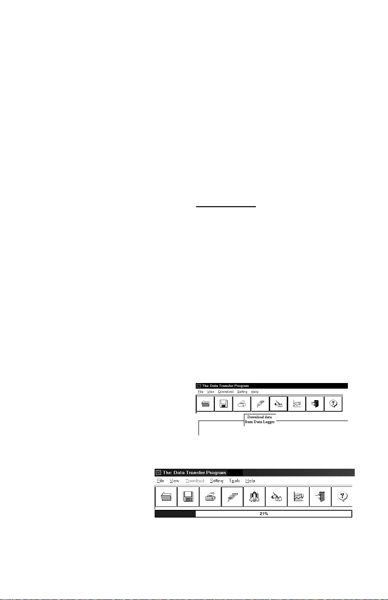
4. The program will open with a
blank window showing no text or
graph. Connect the OM-DLAC
now if it is not already connected.
On the toolbar located along the
top of the screen click on the Download data from Data Logger button. A
Data Transfer window will open.
5. The program will begin
to retrieve the
recording. A status bar
along the top of the
window will show the
progress of information being retrieve d.
6. When the information has been retrieved, the program will automatically dis-
play the recording in the current mode that has been selected. If you have
5
Page 6
AC Current Data Logger
been using the text mode, then the recording will be displayed in the text
mode. If you have been using the graph mode, then the recording will be
displayed as an auto scaled graph.
VIEWING A RECORDING AS A GRAPH
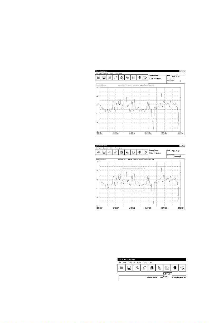
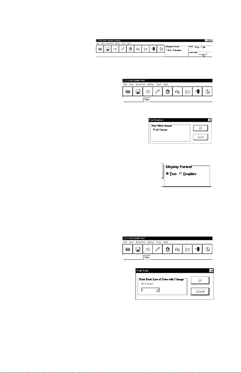
1. When information is re-
trieved or when a file is
opened it will automatically
be displayed in the most recently used mode. To view a
recording as a graph, select
the graph option in t he Display Format box. The program will display the entire
recording as a plotted graph
with the AC Cu rrent on the
vertical scale and the time
on the horizontal scale.
2. To zoom to a particular part
of the graph, place the
mouse cursor in a corner of
an imaginary box that will
enclose the area of interest.
3. Press and hold the left
mouse button and move the
cursor in a diagonal direction from the original position of the cursor. A dashed
line forming a box will be
displayed. Move the cursor
until the box encloses the
area of interest and release the left mouse button.
4. The box will now be stationary on the screen. Move the mouse cursor so
that it is inside the box and click the left mouse button.
5. The enclosed area of the box will now be zoomed so that it fills the entire
window. This may be repeated if additional magnification of an area of the
graph is desired.
6. To return to the original graph with no
auto scaling, click on the Full Graph
button.
6
Page 7
AC Current Data Logger
7. To auto-scale the
graph, click on the
Auto Scale button. The
graph will automatically
be readjusted to fill the vertical axis of the screen.
8. The graph on the screen may be
printed at any time by clicking on
the Print button. Note that the
printout will be what is displ aye d
on the screen when the button is
clicked.
9. A prompt window will open in the middle of
the screen. Click OK to print, or Cancel if
you change your mind.
VIEW A RECORDING AS TEXT
1. When a recording is retrieved, or when a saved
recording is opened, it is displayed in the most recently used mode. The recording can be viewed
as a text listing or a plotted graph.
2. To view a recording as text when a graph is on the screen, click the Text
button located in the display box.
3. Use the Windows™ scroll bar on the right hand side of the screen to scroll
through the text information
4. To print the text information as
text data, click on the Print
button. A window will open in the
middle of the screen. In the lower
left of the window will be a dropdown menu which will allow you to select the number of amps the AC Current
has to change before the new value is
printed. This feature will prevent needless printing of the AC Current when no
change in the current ha s occurred. If
you wish to print all the recorded information, leave this value at zero.
5. When you have selected the amount of AC Current change to print (if any),
click on the OK button to start printing.
7
Page 8
AC Current Data Logger
DATA LOGGER CALIBRATION
You can calibrate the OM-DLAC data logger to make its reading match an external reference or standard. Set the OM-DLAC sampling rate long enough to allow
the logger and reference AC Current to stabilize. Make a recording along with an
external reference in a controlled environment so that the reference AC Current
for the second sample can be measured and recorded.
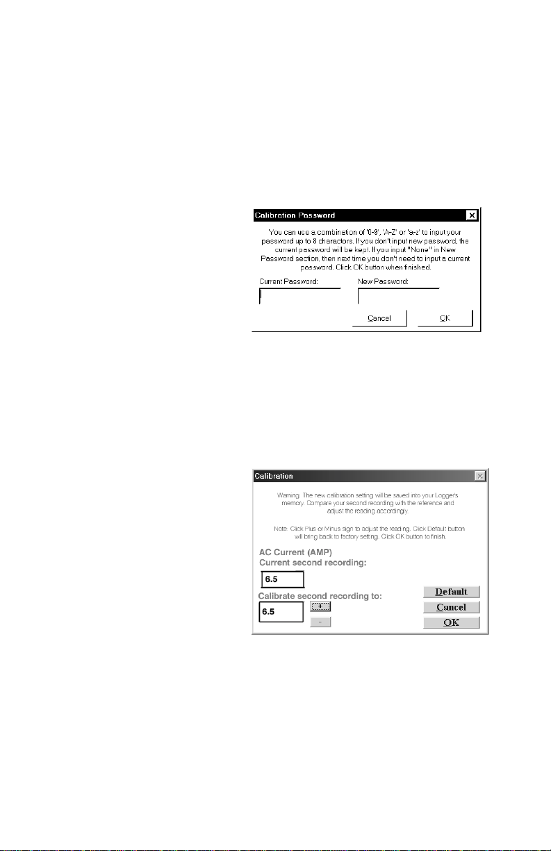
The calibration routine will use
the second recording sample to
make the logger reading match
with the external reference. Click
Tools on the menu and click
Calibrate Logger. A calibration
password window will open. Type
your password in the Current
Password section. If you want to
have a new password next time,
you can type a new password in the New Password section. Click the OK button
when finished. If this is the first time you are calibrating the OM-DLAC, no password is needed. You can click the OK button or press the Enter key to continue.
If you have typ ed a password before and you don ’t want password protection fo r
the calibration function, you can input None as the new password and this will
clear the password protectio n.
After you type the correct current
password and click OK, a
calibrat ion window wi l l open. You
can click the plus or minus
button to make the data logger
reading match with the reference
reading that you recorded at the
same time and same place with
the OM-DLAC. Click t h e OK
button and the software will
make a new data retrieval based
on your new calibration setting.
The new calibration setting will be saved in the OM-DLAC and apply to all future
recordings.
BATTERY REPLACEMENT
The OM-DLAC Data Logger uses a 9-Volt Alkaline battery, which will have an
average life of 1 year. The actual life of the battery will depend on a variety of
factors such as the temperature the battery is used in, the sampling rate of the
logger, and how often the OM-DLAC is used. Extreme temperatures will result in
reduced battery life. If the battery is exhausted during a recording, the OM-DLAC
8
Page 9

AC Current Data Logger
will automatically terminate the recording and save any data recorded up to that
point. The LED will stop flashing and the OM-DLAC will not allow a new recording to be started until the battery has been replaced. Recorded data can be retrieved regardless of the condition of the battery.
When the logger will not be used for an extended period, or when the battery is
exhausted, it is strongly recommended to remove the battery to avoid damage
to the logger from battery leakage. Use only Alkali ne ba tteries in the
OM-DLAC. Substitution of a different battery can result in reduced performance or permanent damage to this instrument.
To replace the OM-DLAC’s battery follow the steps below:
1. Make sure the logger is not set in the recording position. If so, slide the door
open. Any information recorded up to this point will not be lost and is automatically saved.
2. Remove the rear battery cover.
3. The battery and battery clip may be extended from the battery compartment
to facilitate replacement.
4. Remove the battery from the logger and dispose of properly. To assure
proper reset of the logger wait at least one minute before connecting new
battery.
5. Line up the connector of the new battery and push onto the pins of the bat-
tery clip with a firm motion. Do NOT reverse the battery connection, even
momentarily, as this can result in loss of data or permanent damage to
the logger.
6. Place the battery in the battery compartment of the OM-DLAC.
7. Replace the battery cover.
Once the battery has been replaced it will be necessary to reset the logger’s
internal clock. Refer to the section, “Setting the Data Logger” for instructions on
how to do this.
9
Page 10
AC Current Data Logger
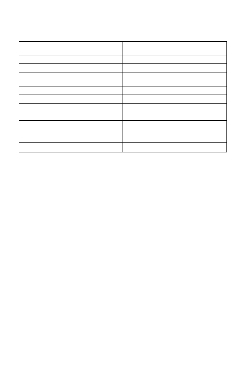
OM-DLAC SPECIFICATIONS
Ambient Operating Temperature
Range
Storage Temperature -40°F to +170°F (-40°C to +76°C)
Time Accuracy +/- 100ppm @ 75°F
Current Range 0 to 300 Amps AC using supplied
Current Resolution 0.1 Amp AC
Current Accuracy +/- 5%
Memory Capacity 16,000 Data Samples
Size 2.5˝ x 3.6˝ x 1.1˝
Weight 0.26 lbs.
Power Source 9 Volt Alkaline Battery
Battery Life 1 year (Average use)
+10°F to +150°F (-12°C to +65°C)
clamp-on probe
(Not Supplied)
10
Page 11
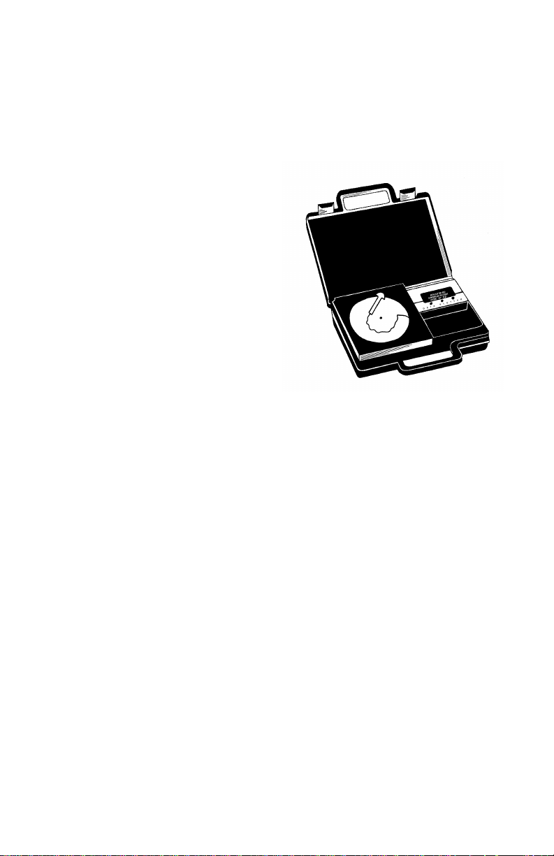
OM-DP3 DATA PLOTTER
The OM-DP3 is an optional accessory
instrument that allows the user to
retrieve data and program data
loggers in the field without the need of
a computer. Using the OM-DP3 you
can plot recorded information from a
data logger or change the settings of a
data logger prior to making a different
data recording. The OM-DP3 can be
operated from batteries or from the
supplied AC adapter. The OM-DP3
uses a series of structured menus to
provide a user friendly intuitive style of
operation. The OM-DP3 also serves as
a conventional temperature recorder.
AC Current Data Logger
11
 Loading...