

Page 1
omega.com
e-mail: [email protected]
For latest product manuals:
omegamanual.info
Shop online at
User’s Guide
OMB-DAQBOOK-2000 AEX SERIES
16-Bit, 200 kHz Multifunction Data Acquisition Systems
OMB-1103-0901 rev 3.0
Page 2

OMEGAnetSM On-Line Service
http://www.omega.com
USA:
Canada:
For immediate technical or application assistance:
USA and Canada:
Mexico and
Latin America:
Internet e-mail
Servicing North America:
One Omega Drive, Box 4047
Stamford, CT 06907-0047
Tel: (203) 359-1660
e-mail: [email protected]
976 Berger
Laval (Quebec) H7L 5A1
Tel: (514) 856-6928
e-mail: [email protected]
Sales Service: 1-800-826-6342 / 1-800-TC-OMEGASM
Customer Service: 1-800-622-2378 / 1-800-622-BEST
Engineering Service: 1-800-872-9436 / 1-800-USA-WHEN
TELEX: 996404 EASYLINK: 62968934 CABLE: OMEGA
SM
Tel: (95) 800-TC-OMEGA
En Espanol: (95) 203-359-7803
FAX: (203) 359-7700
FAX: (514) 856-6886
FAX: (95) 203-359-7807
e-mail: [email protected]
SM
SM
Servicing Europe:
Benelux:
Czech Republic:
France:
Germany/Austria:
United Kingdom:
It is the policy of OMEGA to comply with all worldwide safety and EMC/EMI regulations that
apply. OMEGA is constantly pursuing certification of its products to the European New Approach
Directives. OMEGA will add the CE mark to every appropriate device upon certification.
The information contained in this document is believed to be correct but OMEGA Engineering, Inc. accepts
no liability for any errors it contains, and reserves the right to alter specifications without notice.
WARNING:
These products are not designed for use in, and should not be used for, patient-connected applications.
Postbus 8034, 1180 LA Amstelveen, The Netherlands
Tel: (31) 20 6418405
Toll Free in Benelux: 06 0993344
e-mail: [email protected]
ul. Rude armady 1868
733 01 Karvina-Hranice
Tel: 420 (69) 6311899
e-mail:[email protected]
9, rue Denis Papin, 78190 Trappes
Tel: (33) 130-621-400
Toll Free in France: 0800-4-06342
e-mail: [email protected]
Daimlerstrasse 26, D-75392 Deckenpfronn, Germany
Tel: 49 (07056) 3017
Toll Free in Germany: 0130 11 21 66
e-mail: [email protected]
25 Swannington Road,
Broughton Astley, Leicestershire,
LE9 6TU, England
Tel: 44 (1455) 285520
FAX: 44 (1455) 283912
Toll Free in England: 0800-488-488
e-mail: [email protected]
FAX: (31) 20 6434643
FAX: 420 (69) 6311114
FAX: (33) 130-699-120
FAX: 49 (07056) 8540
P.O. Box 7, Omega Drive,
Irlam, Manchester,
M44 5EX, England
Tel: 44 (161) 777-6611
FAX: 44 (161) 777-6622
Page 3
CE Notice
Many products carry the CE marker indicating they comply with the safety and emissions standards of the European
Community. As applicable, we ship these products with a Declaration of Conformity stating which specifications and
operating conditions apply.
Warnings, Cautions, Notes, and Tips
Refer all service to qualified personnel. This caution symbol warns of possible personal injury or equipment damage
under noted conditions. Follow all safety standards of professional practice and the recommendations in this manual.
Using this equipment in ways other than described in this manual can present serious safety hazards or cause equipment
damage.
This warning symbol is used in this manual or on the equipment to warn of possible injury or death from electrical
shock under noted conditions.
This ESD caution symbol urges proper handling of equipment or components sensitive to damage from electrostatic
discharge. Proper handling guidelines include the use of grounded anti-static mats and wrist straps, ESD-protective
bags and cartons, and related procedures.
This symbol indicates the message is important, but is not of a Warning or Caution category. These notes can be of
great benefit to the user, and should be read.
In this manual, the book symbol always precedes the words “Reference Note.” This type of note identifies the location
of additional information that may prove helpful. References may be made to other chapters or other documentation.
Tips provide advice that may save time during a procedure, or help to clarify an issue. Tips may include additional
reference.
Specifications and Calibration
Specifications are subject to change without notice. Significant changes will be addressed in an addendum or revision to
the manual. As applicable, we calibrate hardware to published specifications. Periodic hardware calibration is not
covered under the warranty and must be performed by qualified personnel as specified in this manual. Improper
calibration procedures may void the warranty.
987696
iii
Page 4
Your order was carefully inspected prior to shipment. When you receive your system, carefully
unpack all items from the shipping carton and check for physical signs of damage that may have
occurred during shipment. Promptly report any damage to the shipping agent and your sales
representative. Retain all shipping materials in case the unit needs returned to the factory.
CAUTION
Using this equipment in ways other than described in this manual can cause
personal injury or equipment damage. Before setting up and using your
equipment, you should read all documentation that covers your system.
Pay special attention to Warnings and Cautions.
Note:
PDF
1103-0901
PDF
457-0909
During software installation, Adobe
®
PDF versions of user manuals will automatically
install onto your hard drive as a part of product support. The default location is in the
Programs group, which can be accessed from the Windows Desktop. Initial navigation
is as follows:
Start [Desktop “Start” pull-down menu]
⇒ Programs
⇒ Omega DaqX Software
You can also access the PDF documents directly from the data acquisition CD by using
the <View PDFs> button located on the opening screen.
Refer to the PDF documentation for details regarding both hardware and software.
®
A copy of the Adobe Acrobat Reader
is included on your CD. The Reader provides
a means of reading and printing the PDF documents. Note that hardcopy versions of
the manuals can be ordered from the factory.
DaqBook2000 Series Users Manual.pdf
Contains the DaqBook/2000 Series hardware-related and software-related chapters, as
well as links to the .pdf files listed below. This pdf file, plus the following constitute
a complete set of documentation for the DaqBook/2000 Series Devices.
DaqView_DaqViewXL.pdf
Discusses how to install and use these “out-of-the-box” data acquisition programs.
iv
PostAcquisition Analysis.pdf
This pdf consists of two documents. The first discusses eZ-PostView, a post data
PDF
1086-0926
1086-0922
acquisition analysis program. The application is included free as a part of product
support. The second includes information regarding eZ-FrequencyView and
eZ-TimeView. These two applications have more features than does eZ-PostView
and are available for purchase. They can; however, be used freely during a 30-day
trial period.
927096
Page 5

PDF
457-0905
PDF
1008-0901
Manual Layout
DaqBook/2000 Series Installation Guide – Discusses how to install software, connect hardware,
System Connections and Pinouts – Provides pinouts of P1, P2, P3, and P4. The document includes
Chapter 1 – Operational Overview. This chapter briefly discusses the modular concept of “Daq”
DBK Options.pdf
The DBK Option Cards and Modules User’s Manual discusses each DBK product.
In addition, the document includes chapters on signal management, system
connections, pinouts, DBK set up in software, and troubleshooting.
ProgrammersManual.pdf
The Programmer’s Manual pertains to developing custom programs using
Applications Program Interface (API) commands.
Programmers should check the readme.file on the install CD-ROM for the location of
program examples included on the CD.
and test the system.
an overview of several DBK200 Series adapters that can be used for system expansion from a
DaqBook/2000 Series device P4 connector.
systems and includes a DaqBook/2000 Series block diagram, information regarding scanning,
triggering, synchronous and asynchronous I/O operations, and the use of DBK cards and
modules for signal conditioning. The chapter includes material regarding the DBK46 card
option, which provides the host unit with four Digital-to-Analog Converters (DACs).
DBK Basics – Discusses option cards and modules (DBKs) that can be used to enhance and
expand data acquisition systems.
Chapter 2 – DBK46 Reference Discusses optional 4-channel analog output card that can be used to
provide a DaqBook/2000 Series model with four DAC channels.
Chapter 3 – CE Compliance and Noise Considerations pertains to CE standards and operating
conditions relevant to DaqBook/2000 Series Systems. CA-209D CE Cable Kit Instructions
(p/n 1103-0902) and Ethernet CE Kit Installation Instructions (p/n 1107-0901) are included at
the end of the chapter.
Chapter 4 – Calibration lists the order in which to perform adjustments and briefly discusses
DaqCal.exe, a program that provides on-screen instruction, graphics, and prompts.
Chapter 5 – Specifications
Chapter 6 – Fuse Replacement
Chapter 7 – Troubleshooting and Customer Support
Dimensional Drawings
Glossary
Reference Note:
Reference to additional documents, of importance to the DaqBook/2000 Series,
begins on the preceding page.
DaqBoard 2000 Series User’s Manual
927096
v
Page 6

This page is intentionally blank.
vi
927096
Page 7

Table of Contents
Installation Guide …… IG-1
A Comparison of Device Features …… IG-4
Connecting a DaqBook/2000A or DaqBook/2000X to a PC Parallel Port …. [Section A]
Connecting a DaqBook/2000E or WaveBook/516E to the Ethernet …. [Section B]
Connecting a DaqBook/2000A or DaqBook/2000X to a DaqBook/2000E …. [Section C]
Appendices
Device Connector Reference ….. Appendix D
System Expansion …… Appendix E
Adding a Parallel Port to the PC …… Appendix F
TCP/IP and Resource Tests …… Appendix G
System Connections and Pinouts …… sc-1
Overview …… sc-1
P1 – Analog I/O …… sc-3
P2 – Digital I/O …… sc-4
P3 – Pulse/Frequency/Digital I/O …… sc-5
P4 to P1, P2, and P3 Correlation …… sc-6
DBK200 Series, Selected P4 Connector Options …… sc-9
1 – Operational Overview
Daq Systems, the Modular Concept …… 1-1
Block Diagram and Basic Features…... 1-3
Scanning …… 1-6
Triggering …… 1-7
Synchronous I/O Operations …… 1-8
Asynchronous I/O Operations …… 1-12
Using DBK Cards and Modules for Signal Conditioning ……1-13
Daq Software …… 1-13
DBK Basics
Introduction……
DBK Basics-
How Do DBKs Connect to the Data Acquisition Device? ……
DBK Identification Tables …..
Tips on Setting up a Data Acquisition System ……
Power Supplies and Power Connectors ……
An Introduction to Power-Related DBKs …..
Power Requirements ……
Calculating Your System’s Power Needs ……
Additional Reading …..
1
DBK Basics-
DBK Basics-
DBK Basics-
20
15
9
DBK Basics-
DBK Basics-
DBK Basics-
DBK Basics-
12
14
17
2 – DBK46 – A Reference for DaqBook/2000 Series Users
DaqBook/2000 User’s Manual
vii
927096
DBK Basics-
11
2
Page 8

3 - CE-Compliance and Noise Considerations
Overview ……3-1
CE Standards and Directives ……3-1
Safety Conditions ……3-2
Emissions/Immunity Conditions ……3-2
CE Enhancements for DBKs ...3-3
CE Compliance for DaqBook/2000 Series System Expansion …… 3-3
Noise Considerations …… 3-4
CA-209D, CE Cable Kit Instructions
Ethernet CE Kit Installation Instructions
4 – Calibration
5 – Specifications
6 – Fuse Replacement
General Information …… 6-1
DaqBook/2000A …… 6-2
DaqBook/2000X …… 6-3
DaqBook/2000E …… 6-5
7 – Troubleshooting and Customer Support
(p/n 1103-0902)
(p/n 1077-0901)
Electrostatic Discharge (ESD), Handling Notice…… 7-1
Product Care …… 7-1
ReadMe Files and the Install CD-ROM ……7-2
Driver Support……7-2
Ethernet Problems …… 7-2
Parallel Port Problems ……7-3
Frequently Asked Questions …… 7-6
Customer Support …… 7-9
Dimensional Drawings
Glossary
viii
927096
DaqBook/2000 Series User’s Manual
Page 9
Installation Guide
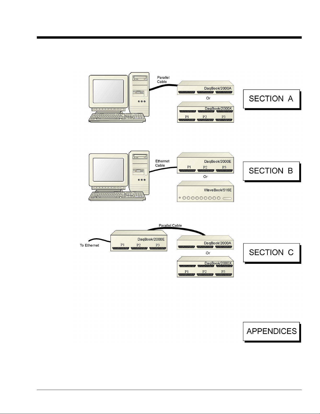
A Comparison of Device Features …… IG-4
Connecting a DaqBook/2000A or DaqBook/2000X to a PC Parallel Port [Section A]
Connecting a DaqBook/2000E, or WaveBook/516E to the Ethernet [Section B]
Connecting a DaqBook/2000A or DaqBook/2000X to a DaqBook/2000E [Section C]
Appendix D – Device Connector Reference
Appendix E – System Expansion
Appendix F – Adding a Parallel Port to the PC
Appendix G – TCP/IP and Resource Tests
Installation Guide
927796
IG-1
Page 10
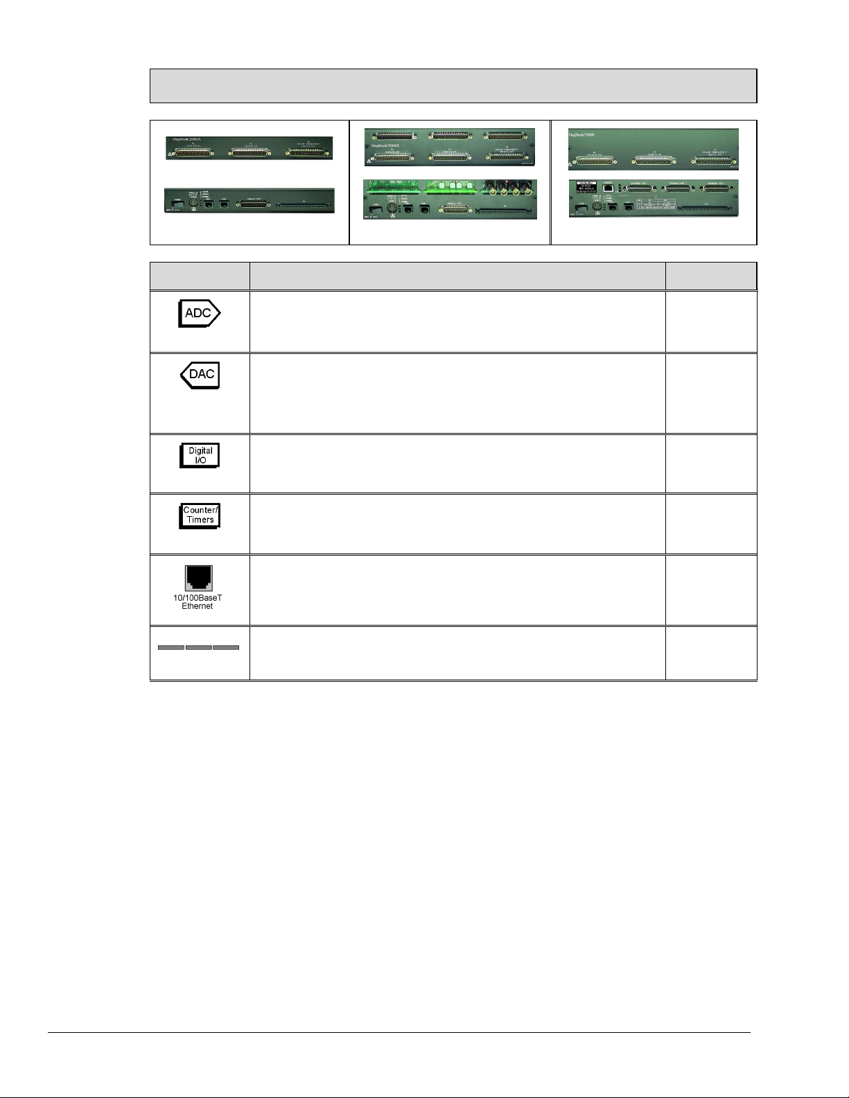
A Comparison of Device Features
DaqBook/2000A
DaqBook/2000X
DaqBook/2000E
Feature Description Applies to:
16
4
(with DBK46)
40
6
3 Card Exp.
Analog Input Channels
Analog Input signals enter through P1 and/or P4, go to MUX, to PGA, to Gain
& Offset Amplifier, then to Analog-to-Digital Converter (ADC).
Analog Output Channels [Available only with DBK46 Option]
Digital Signals go through Digital-to-Analog Converters via the optional
DBK46 plug-in card, then through “DAC Out” on P3 and P4. The card
includes a 256K Sample Buffer. Note that the DBK46 option is a “Factory
Install” Option Only.
Digital I/O Channels
Digital signals pass through one 16-bit Digital I/O Port and three 8-bit Digital
I/O Ports located on P2, P3, and/or P4.
Counter/Timers
Four 16-bit Counter Input signals and Two 16-bit Timer Output signals via P3
and/or P4 and System Controller.
10/100BaseT Ethernet Interface located on the chassis
The
DaqBook/2000E includes a 10/100BaseT Ethernet interface.
Note that DaqBook/2000A and DaqBook/2000X can connect to the
DaqBook/2000E, or to a WBK25 Ethernet module.
3 Card Expansion
The
DaqBook/2000X includes three expansion slots that can accept a
wide variety of analog and digital DBK signal conditioning cards.
All Models
Each model,
providing a
DBK46 is
installed.
All Models
All Models
/2000E
/2000X
DaqBook/2000 Series Devices are high-speed, multi-function, data acquisition systems for use with
notebook and desktop PCs. They feature a 16-bit, 200-kHz A/D converter, digital calibration, 40 digital
I/O lines, four counters, and two timers and, if the optional DBK46 card is installed, four 16-bit, 100-kHz
D/A converters.
IG-2
Up to 470 channels of analog and digital I/O can be accessed with one DaqBook/2000 Series Device.
All input and output signals can be connected via the three 37-pin DSUB connectors [P1, P2, and P3]
located on the front panel. Duplicate I/O connectivity is also available on the rear panel via the 100-pin,
P4 connector.
• P1 – Analog input port for 16 single-ended or 8 differential analog inputs with 13 software
programmable ranges (±10 V to ±156 mV full scale).
• P2 – General purpose digital I/O port with 24 lines, or digital I/O expansion port controlling
up to 192 external lines.
• P3 – 16-bit digital I/O port, counter inputs, timer outputs, and analog outputs.
• P4 – this 100-pin connector allows for optional connection to a DBK200 Series Device for
expansion from the rear panel. P4 connectivity provides no additional I/O to that which is
available to P1, P2, and P3.
927896
Installation Guide
Page 11
Section A
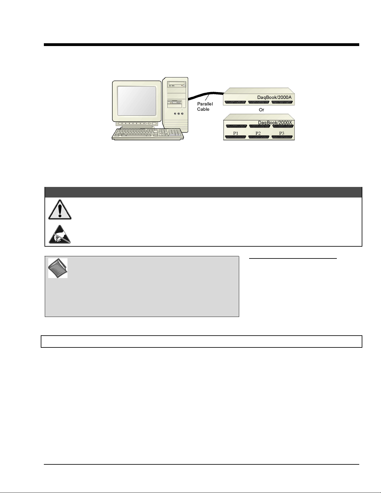
Connecting a DaqBook/2000A or a DaqBook/2000X to a PC Parallel Port
Connecting a DaqBook/2000A or a DaqBook/2000X to a PC Parallel Port
CAUTION
Turn off power to the system devices and externally connected equipment before connecting cables.
Electric shock or damage to equipment can result even under low-voltage conditions.
Take ESD precautions (packaging, proper handling, grounded wrist strap, etc.)
Reference Note: Adobe PDF versions of user manuals will
automatically install onto your hard drive as a part of product
support. The default location is in the Programs group,
which can be accessed from the Windows Desktop. You can
also access documents directly from the data acquisition CD
via the <View PDFs> button located on the CD’s opening
screen.
STEP A.1 –
Remove
1.
Programs feature.
2. Place the Data Acquisition CD into the CD-ROM drive. Wait for PC to auto-run the CD. This may take a
few moments, depending on your PC. If the CD does not auto-run, use the Desktop’s Start/Run/Browse
feature to locate and run the CD’s setup.exe file.
3. After the intro-screen appears, follow the screen prompts.
Minimum System Requirements
PC system with Pentium® Processor
Windows Operating System
RAM, as follows:
32 Mbytes of RAM for Windows 95/98/NT
64 Mbytes of RAM for Windows Me
64 Mbytes of RAM for Windows 2000
64 Mbytes of RAM for Windows XP
Install the Software
previous version Daq drivers, if present. You can do this through the Windows Add/Remove
Installation Guide / Section A
927796
Connecting a DaqBook/2000A or /2000X to a PC Parallel Port IG / A-1
Page 12
STEP A.2 –
Connect the DaqBook/2000A or DaqBook/2000X to a Parallel Port
What you will need
• A computer with an available parallel port. If your PC has no parallel port available, refer to
this guide's Appendix F, Adding a Parallel Port to the PC, which begins on page IG / F-1.
• One parallel port cable, e.g. a CA-35-2 (2-foot) or a CA-35-12 (1-foot) cable.
How to make the connection:
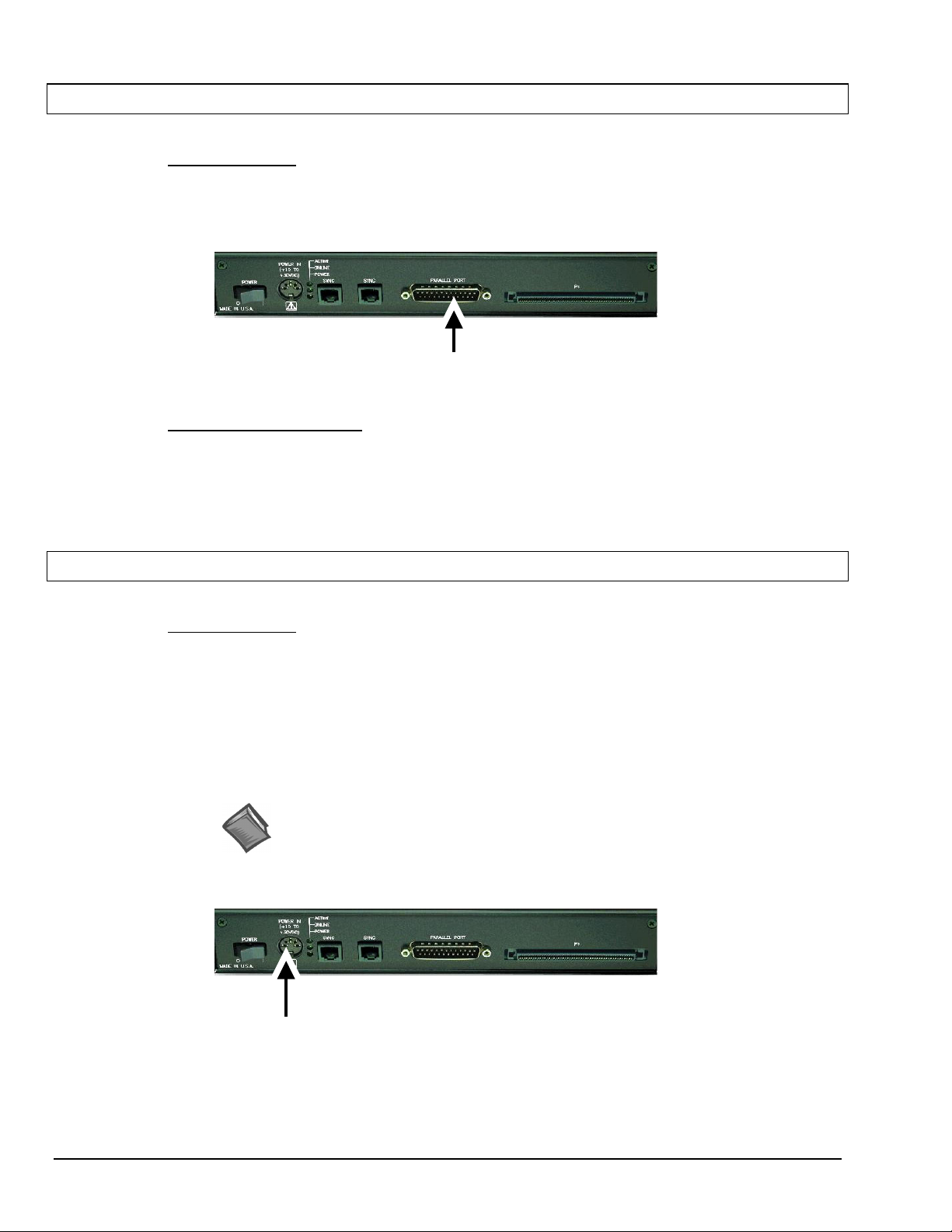
1. Connect the parallel port cable to the parallel port connector on the rear panel of the
DaqBook/2000A or DaqBook/2000X.
2. Connect the other end of the cable to the parallel port connector on the PC.
:
DB25 Parallel Port Connector
STEP A.3 –
Connect the System to Power
What you will need
A power supply with a range of +10 VDC to +30 VDC.
The power supply needs to have a male DIN5 connector.
Note: The switching-mode power supply that is commonly used with DaqBook/2000 Series
Note: Various AC adapter models support power grids of USA, Europe, Japan, and Asia.
DIN5 POWER IN Connector (+10 to +30 VDC)
:
systems has an input range of 100 VAC to 240 VAC at 50 Hz to 60 Hz. The power
supply’s output [to the DaqBook/2000 Series device] is 15 VDC @ 2.7 amps via a DIN5
connector.
Reference Note: It is possible to use a VDC power source other than the commonly
used switching-mode power supply, often referred to as an adapter. However, be sure
to consult the power-related sections of DBK Basics before doing so. The DBK Basics
segment immediately follows chapter 1 of this user’s manual.
IG / A-2 Connecting a DaqBook/2000A or /2000X to a PC Parallel Port
927796
Installation Guide / Section A
Page 13
How to make the connection:
1. Place the DaqBook/2000 Series device power switch in the “OFF” (0) position, if it is not
already OFF.
2. Connect the DIN5 end of the adapter’s cable to the power in connector on the DaqBook/2000
Series device (see the preceding figure).
If you plan to use a power source other than the adapter, consult the power-related sections of
DBK Basics before doing so. The DBK Basics segment immediately follows chapter 1 of this
user’s manual.
3. Connect the adapter’s plug to a standard AC outlet.
4. If your adapter has a power switch, position it to “ON.”
T
urn ON the DaqBook/2000 Series device’s power by placing the power switch to the “1”
5.
position. The power led will light up.
STEP A.4 –
Configure and Test the Hardware
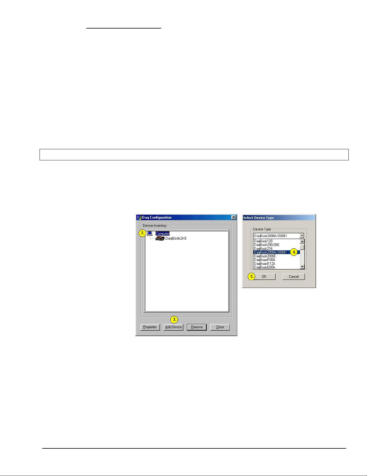
1. Run the Daq*Configuration control panel applet. The applet can be accessed by navigating
from the Windows’ Desktop as follows:
Start ⇒ Settings ⇒ Control Panel ⇒ Daq* Configuration
2. Select the “Computer” image in the Device Inventory configuration tree (see figure).
3. Click the <Add Device> button. The “Select Device Type” box will appear.
4. Select “DaqBook2000A/2000X” from the “Device Type” scroll-down.
Note that the default name that appears in the Device Inventory configuration tree, e.g.,
“DaqBook2K0” can be renamed.
5. Click the <OK> button. The “Properties” box will appear for the selected device.
6. Ensure settings are correct, and make changes if needed. Refer to the following table for
throughput speeds.
Installation Guide / Section A
927796
Connecting a DaqBook/2000A or /2000X to a PC Parallel Port IG / A-3
Page 14
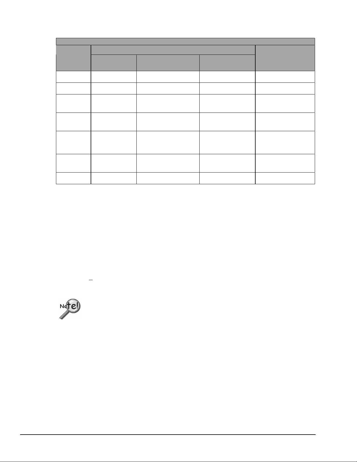
Support for Parallel Port Communication Protocols
Protocol
Device Type, Applicability to
WaveBooks DaqBook/2000
Series
LogBooks
Estimated
Throughput
(Note 2)
4 bit Yes Yes No 40 to 50 Ks/sec
8 bit Yes Yes No 80 to 100 Ks/sec
SMC666
Yes Yes No 350 to 370 Ks/sec
EPP
Fast EPP
Yes Yes
(Note 1)
No 500 Ks/sec
(WBK20)
Fast EPP
Yes Yes No 1.2 / Ms/sec
(WBK21)
Fast EPP
Yes Yes No 500 Ks/sec
(WBK23)
ECP Yes Yes Yes 350 to 400 Ks/sec
Note 1: No Windows NT support.
Note 2: The values of expected throughput are estimates only. Actual thru-put may vary due to the specific
parallel port capabilities and BIOS settings of the computer involved.
7. Select the “Test Hardware” tab.
8. Verify that the DaqBook/2000 Series device has been properly installed and powered-on. Proper
installation includes the parallel port cable being firmly in place on both the DaqBook/2000 Series device
and on the host PC’s parallel port.
9. Click the <Resource Test> button.
Appendix G, TCP/IP and Resource Tests, includes a brief explanation of the test. See page IG / G-1.
10. Click the <T
est> button.
Testing the DaqBook/2000 Series device may, in some cases, cause the system to hang.
If test results are not displayed in 30 seconds or the system does not seem to be responding,
reboot the system. Upon power-up, re-enter the Daq Configuration and change the
DaqBook/2000 Series device configuration settings to those that work properly.
This completes the instructions for connecting a DaqBook/2000A or a DaqBook/2000X to a PC parallel port.
At this point you should refer to other sections of the manual for additional system information. The manual
includes pinouts, information on system expansion, and data acquisition.
IG / A-4 Connecting a DaqBook/2000A or /2000X to a PC Parallel Port
927796
Installation Guide / Section A
Page 15
Section B
Connecting a DaqBook/2000E or WaveBook/516E to the Ethernet
Connecting a DaqBook/2000E or WaveBook/516E to the Ethernet
Introduction
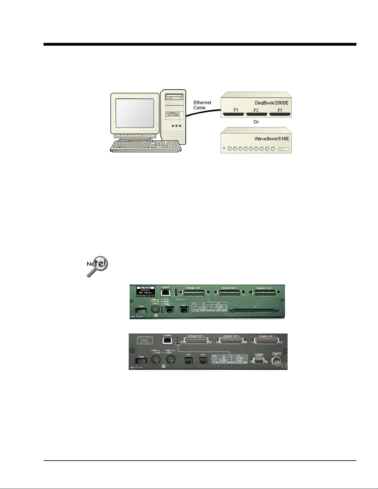
The DaqBook/2000E and WaveBook/516E connect directly to an Ethernet port on a PC or network hub via
the their built-in 10/100BaseT Ethernet interface. An Ethernet patch cable CA-242 (1.5 foot) or CA-242-7
(7 foot) cable is used to make the connection.
Contact the factory or your service representative in regard to Ethernet connectivity if
your operating system is other than Windows NT, Windows 2000, or Windows XP.
The DaqBook/2000E and WaveBook/516E can be used as Ethernet interface devices for sister
products that are not capable of direct Ethernet connection.
DaqBook/2000E
WaveBook/516E
Installation Guide / Section B
927796
Connecting a DaqBook/2000E or WaveBook/516E to the Ethernet IG / B-1
Page 16
CAUTION
Turn off power to the system devices and externally connected equipment before connecting cables.
Electric shock or damage to equipment can result even under low-voltage conditions.
Take ESD precautions (packaging, proper handling, grounded wrist strap, etc.)
Reference Note: Adobe PDF versions of user manuals will
automatically install onto your hard drive as a part of product
support. The default location is in the Programs group, which
can be accessed from the Windows Desktop. You can also
access documents directly from the data acquisition CD via the
<View PDFs> button located on the CD’s opening screen.
STEP B.1 –
Remove
1.
Programs feature.
2. Place the Data Acquisition CD into the CD-ROM drive. Wait for PC to auto-run the CD. This may take a
few moments, depending on your PC. If the CD does not auto-run, use the Desktop’s Start/Run/Browse
feature to locate and run Setup.exe [from the applicable CD-ROM drive].
3. After the intro-screen appears, follow the screen prompts.
STEP B.2 –
Determine the type of Network Connection
Minimum System Requirements
PC system with Pentium® Processor
Windows Operating System
RAM, as follows:
32 Mbytes of RAM for Windows 95/98/NT
64 Mbytes of RAM for Windows Me
64 Mbytes of RAM for Windows 2000
64 Mbytes of RAM for Windows XP
Install the Software
previous version Daq drivers, if present. You can do this through Microsoft’s Add/Remove
To properly connect and configure a DaqBook/2000E or a WaveBook/516E, you must determine the type
of network that the device will become part of. This is because the type of network used has a direct
bearing on the IP address of the device.
Briefly, the four network types are as follows:
Dedicated Network - with a direct cable connection from the PC to the device •
•
Dedicated Network - making use of a network hub or switch
•
LAN with a DHCP server
(Local Area Network with a Dynamic Host Configuration Protocol)
•
LAN without a DHCP server
(Local Area Network with no Dynamic Host Configuration Protocol)
Brief descriptions and illustrations follow.
IG / B-2 Connecting a DaqBook/2000E or WaveBook/516E to the Ethernet
927896
Installation Guide / Section B
Page 17
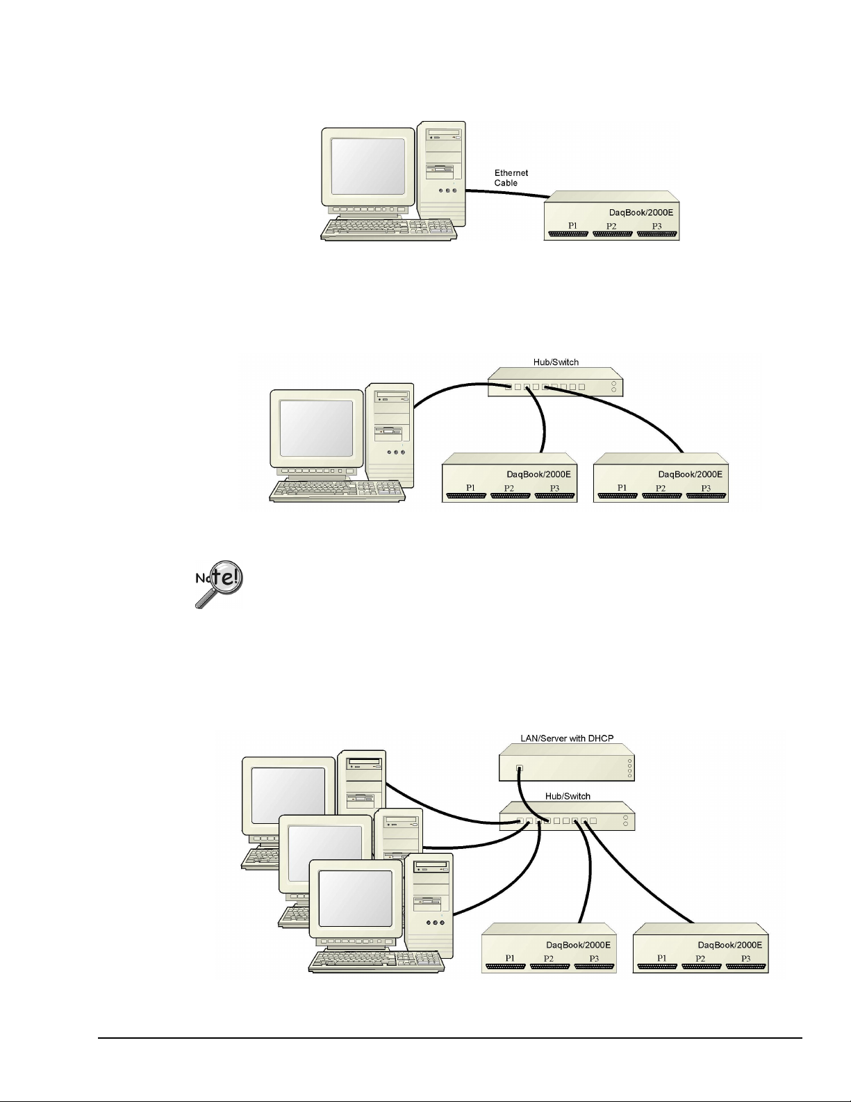
Dedicated Network - with a direct cable connection from the PC to the device
In this scenario a DaqBook/2000E or a WaveBook/516E is connected directly to an Ethernet jack on a host
computer.
Dedicated Network using a Direct Cable Connection
Dedicated Network - making use of a network hub or switch
In this scenario the DaqBook/2000E or WaveBook/516E connects to the Ethernet through a network hub
or switch. At least one computer is also connected to the hub.
Dedicated Network using a Hub/Switch
Some network devices such as a wireless access point may act as a DHCP server. If this is
the case, follow the instructions for the LAN with a DHCP server. For detailed
information consult the documentation that is specific to your network device.
LAN with a DHCP Server (Local Area Network with a Dynamic Host Configuration Protocol server)
Many corporations use the LAN/Server with DHCP arrangement for their networks. In this type of setup
several computers are typically connected to a network that makes use of a DHCP server. In addition, a
DaqBook/2000E or WaveBook/516E is connected to the network hub/switch.
Installation Guide / Section B
927796
LAN with a DHCP Server
Connecting a DaqBook/2000E or WaveBook/516E to the Ethernet IG / B-3
Page 18

Notes:
Using a DaqBook/2000E or WaveBook/516E on a typical LAN may affect the speed of the network
➣
and internet data transfer. Because of this we recommend adding a network card to the computer and
using one of the two dedicated network configurations.
Contact your network administrator before connecting a DaqBook/2000E or a WaveBook/516E
➣
to a corporate network.
LAN with no DHCP Server
(Local Area Network with no Dynamic Host Configuration Protocol server)
This scenario looks the same as that shown in the previous illustration, except there is no Dynamic Host
Configuration Protocol (DHCP). In this type of setup, one or more computers are connected to a network;
and each computer has a static IP address.
STEP B.3 –
Connect the System Components
Reference Note:
For examples of system connections, including cable use, refer to the following sections of the installation
guide as needed: Appendix D, Device Connector Reference; Appendix E, System Expansion; and
Appendix F, Adding a Parallel Port to the PC.
What you will need to connect a DaqBook/2000E or a WaveBook/516E to the Ethernet
• An available connection to the Ethernet. The connection can be either
- an Ethernet jack on a computer or
- an Ethernet jack on a hub that is connected to the Ethernet.
• An Ethernet patch cable, e.g., a CA-242 (1.5 foot cable) or a CA-242-7 (7-foot cable).
1. Connect the Ethernet cable to the Ethernet jack on the DaqBook/2000E or WaveBook/516E.
2. Connect the other end of the Ethernet cable to the Ethernet jack on the host computer or
network hub.
:
IG / B-4 Connecting a DaqBook/2000E or WaveBook/516E to the Ethernet
927896
Installation Guide / Section B
Page 19

STEP B.4 –
Power-up the System Components
What you will need
A power supply with a range of +10 VDC to +30 VDC.
The power supply needs to have a male DIN5 connector.
Note: The switching-mode power supply that is commonly used with these systems has an input
Note: Various AC adapter models support power grids of USA, Europe, Japan, and Asia.
How to make the connection:
1. Using the unit’s power switch, turn the DaqBook/2000E or WaveBook/516E “OFF.
The switch will be in the “0” position and the power LED will be unlit.
2. Connect the DIN5 end of the adapter’s cable to the power in connector on the DaqBook/2000E
or WaveBook/516E.
:
range of 100 VAC to 240 VAC at 50 Hz to 60 Hz. The power supply’s output [to the
device] is typically 15 VDC @ 2.7 amps via a DIN5 connector.
Reference Note: It is possible to use a VDC power source other than the commonly
used switching-mode power supply, often referred to as an adapter. However, be sure
to consult the power-related sections of DBK Basics before doing so. The DBK Basics
segment immediately follows chapter 1 of this user’s manual.
3. Connect the adapter’s plug to a standard AC outlet.
4. If your adapter has a power switch, position it to “ON.”
T
urn ON the DaqBook/2000E or the WaveBook/516E by placing the power switch to the
5.
“1” position. The power led will light up.
Reference Note:
Refer to the power-related sections of DBK Basics before powering up a system. The DBK
Basics segment immediately follows chapter 1 of this user’s manual.
Installation Guide / Section B
927796
Connecting a DaqBook/2000E or WaveBook/516E to the Ethernet IG / B-5
Page 20
STEP B.5 -
Configure the Computer’s Network Settings [Applies to “dedicated networks” only]
If using a LAN (Local Area Network), which has a DHCP server
with STEP B.7 - Configure and Test the System using the Daq*Configuration Applet (page B-10).
If using a LAN (Local Area Network), which has no DHCP server
continue with STEP B.6 - Configure Device Network Settings using DaqIPConfig (page B-9).
1. Open the Control Panel by navigating from the Windows Desktop as follows:
Start Menu ⇒ Settings ⇒ Control Panel.
2. Double-click the “Network and Dial-up Connections” icon.
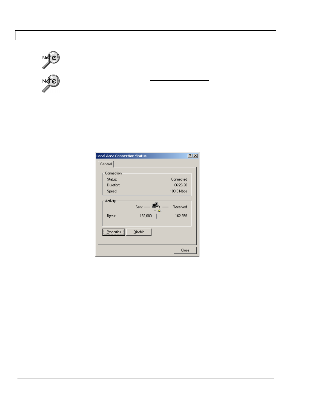
3. Double-click the “Network Connection” icon for the network that the DaqBook/2000E or the
WaveBook/516E is connected to.
, skip this section and continue
, skip this section and
Local Area Connection Status
4. In the “Local Area Connection Status” box (previous figure), click on the <Properties> button.
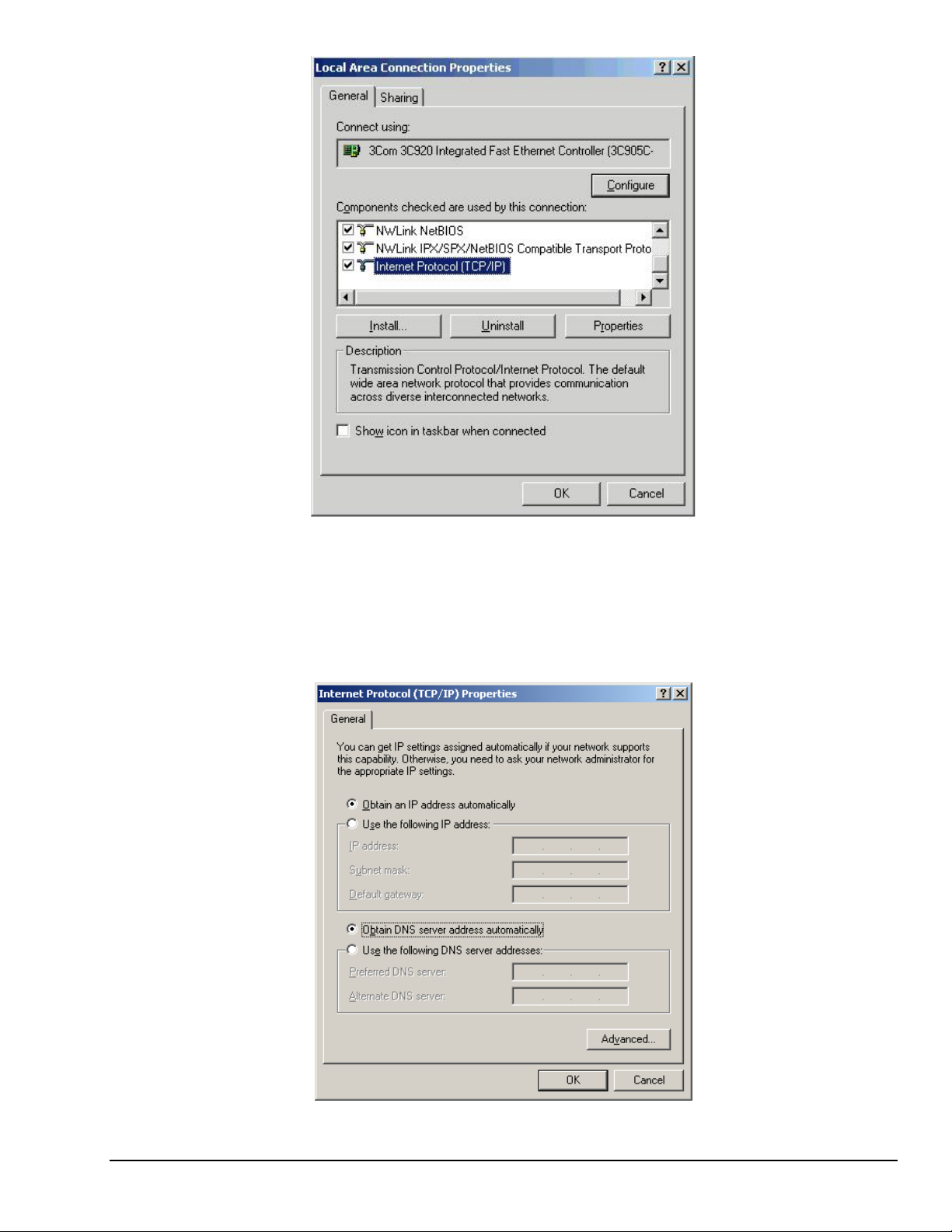
The “Local Area Connection Properties” box will appear (following figure).
IG / B-6 Connecting a DaqBook/2000E or WaveBook/516E to the Ethernet
927896
Installation Guide / Section B
Page 21
Local Area Connection Properties
5. Double-click the “Internet Protocol (TCP/IP)” component (previous figure).
The “Internet Protocol (TCP/IP) Properties” box will appear (following figure).
Installation Guide / Section B
Internet Protocol (TCP/IP) Properties
927796
Connecting a DaqBook/2000E or WaveBook/516E to the Ethernet IG / B-7
Page 22
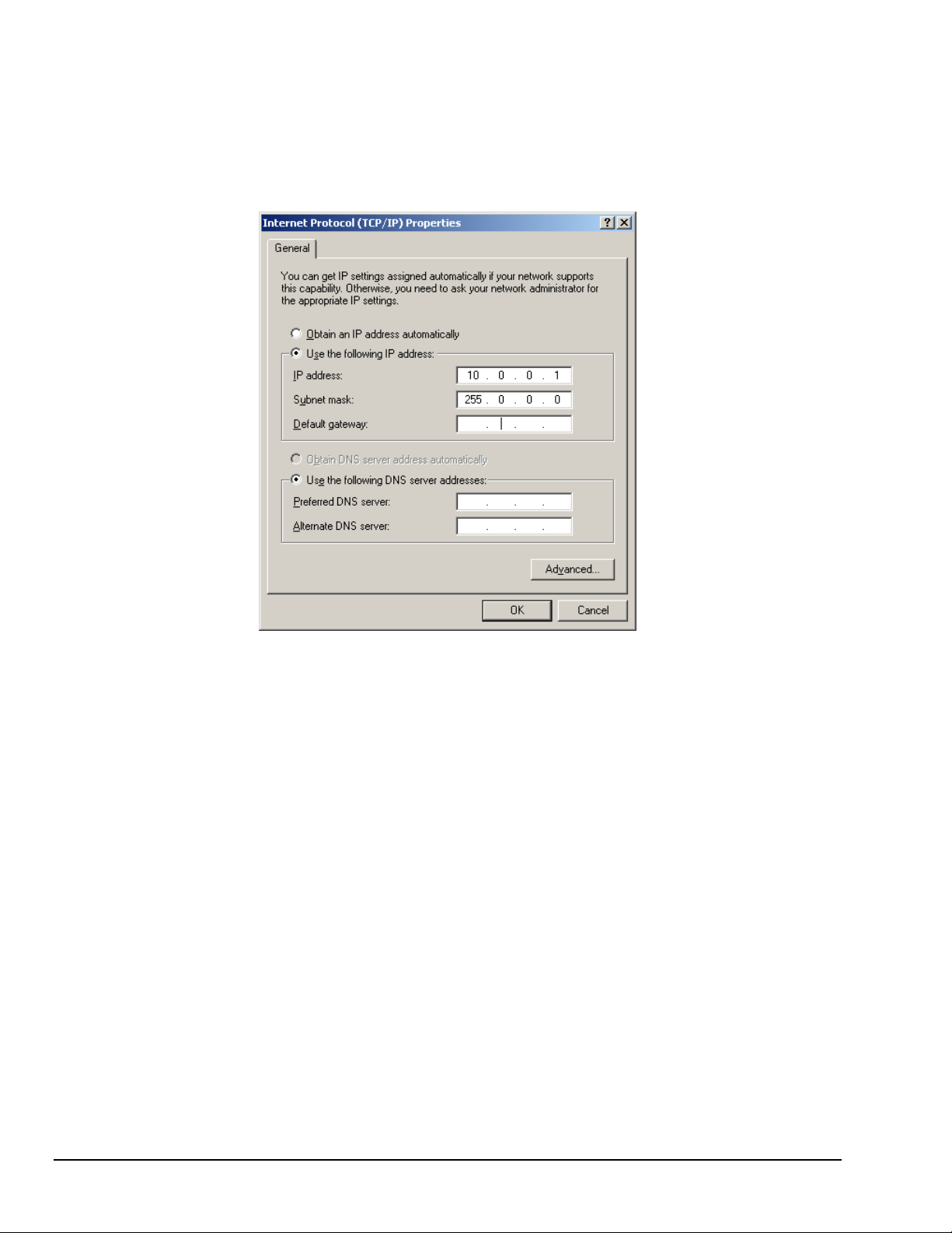
Configure the Computer’s TCP/IP settings as follows.
Internet Protocol (TCP/IP) Properties
6. Select the “Use the following IP Address” radio button.
7. Set the IP address field to 10.0.0.x where x is some number from 1 to 255.
Make sure that each computer on the dedicated network has a unique IP address.
8. Set the Subnet mask to 255.0.0.0. Note that the remaining fields can be left unchanged.
IG / B-8 Connecting a DaqBook/2000E or WaveBook/516E to the Ethernet
927896
Installation Guide / Section B
Page 23
STEP B.6 -
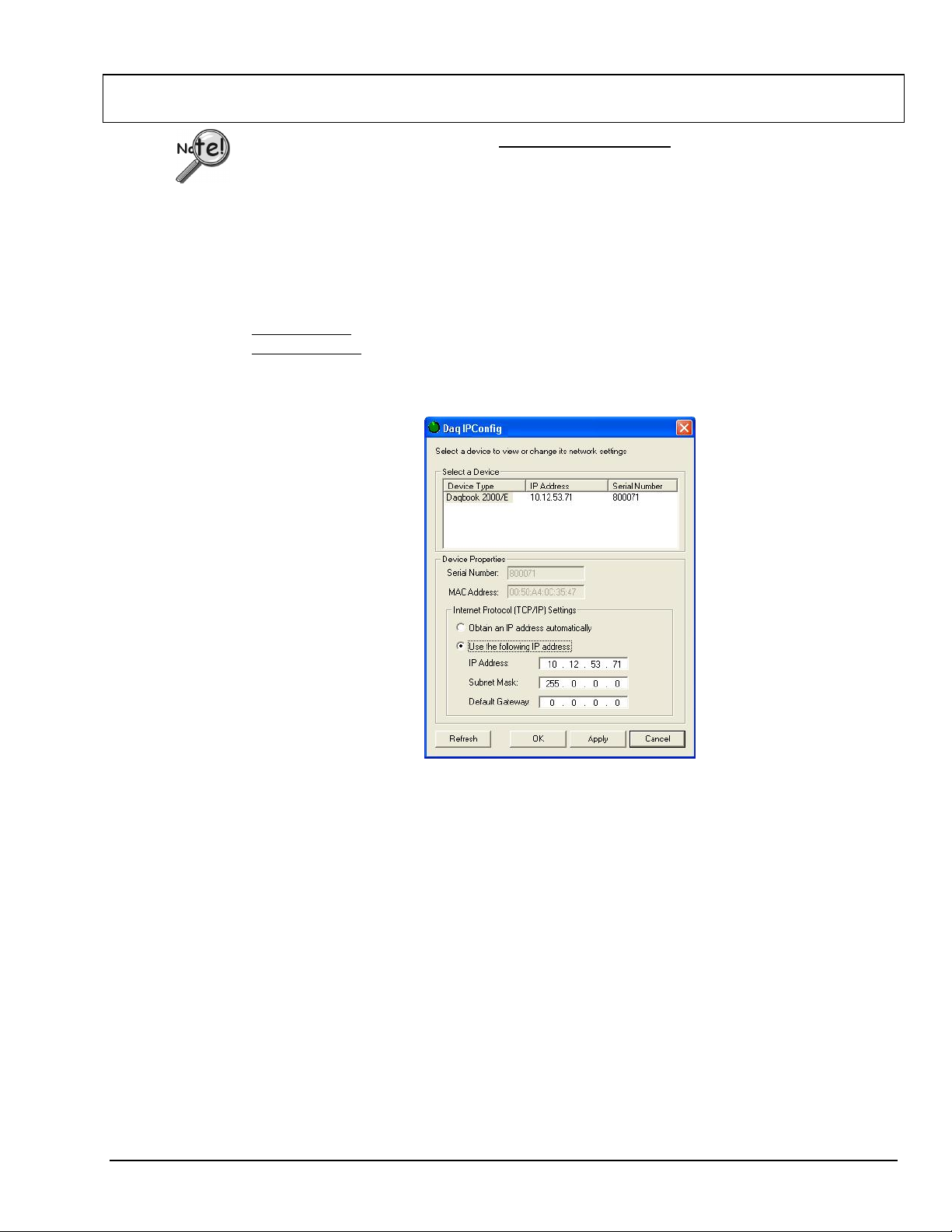
The DaqIPConfig applet, designed for 32-bit Windows /NT/2000/XP systems. DaqIPConfig allows you to change
the IP address of a device to match the address of a host computer. The applet is located in the program group for
the associated device and can be accessed from the Windows Desktop via the start menu.
1. Locate the DaqIPConfig Applet.
2. Open the DaqIPConfig Applet.
Configure Device Network Settings using DaqIPConfig
Applies only to a LAN (Local Area Network), which has a no DHCP server.
If using a LAN (Local Area Network), which has a DHCP server
with STEP B.7 - Configure and Test the System using the Daq*Configuration Applet (page B-10).
Locate the DaqIPConfig applet by navigating from the Windows’ Desktop as follows:
DaqBook Users
WaveBook Users
: Start Menu ⇒ Programs ⇒ Omega DaqX Software ⇒ DaqIPConfig
: Start Menu ⇒ Programs ⇒ Omega WaveBook Software ⇒ DaqIPConfig
Click on the DaqIPConfig selection to open the applet.
, skip this section and continue
3. Select the device that is to have the address change.
Note: In the above figure there is only one device to select, i.e., DaqBook/2000E.
4. Set the internet protocol (TCP/IP) settings to be compatible with host computer.
(a) Select the radio button labeled “Use the following IP address.”
(b) Enter the new internet protocol settings. If needed, consult your network administrator for
acceptable numbers.
(c) Click the <OK> button.
5. Reboot the device.
The new IP address will not take affect until the device has been powered-off, then powered back on.
6. Repeat steps 3, 4, and 5 for other devices in the system.
After configuring the network settings for all devices, proceed to Step B.7.
Installation Guide / Section B
927796
DaqIPConfig
Connecting a DaqBook/2000E or WaveBook/516E to the Ethernet IG / B-9
Page 24
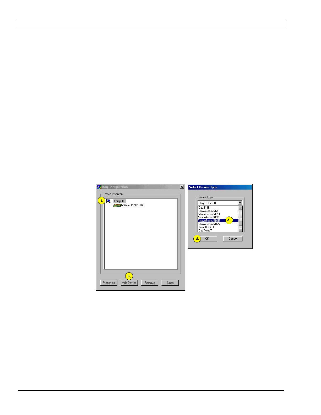
STEP B.7 -
1. Open the Daq* Configuration Applet.
2. Add the first-level device to the list of installed devices.
Configure and test the System using the Daq* Configuration Applet
The Daq* Configuration applet, designed for 32-bit Windows 95/98/Me/NT/2000/XP systems, is located
in the Windows Control Panel. It allows you to add or remove a device and change configuration settings.
The included test utility provides feedback on the validity of current configuration settings, as well as
performance summaries.
a. Open the Control Panel by navigating from the Windows’ Desktop as follows:
Start Menu ⇒ Settings ⇒ Control Panel
b. From the Control Panel, double-click the Daq* Configuration icon.
The first-level device is the device that will be connected directly to the Ethernet, via a host computer’s
Ethernet jack or a jack on a network hub. The DaqBook/2000E and WaveBook/516E are each examples of
first-level devices.
a. Select the Computer image in the Device Inventory configuration tree (following figure).
b. Click the <Add Device> button. The “Select Device Type” box will appear.
c. Select the DaqBook2000E or the WaveBook516E from the list of devices, as applicable.
d. Click the <OK> button. The “Properties” box will appear for the selected device.
Using Daq* Configuration Device Inventory & Select Device Type to Add a Device
Note: Although the above figure indicates that a WaveBook/516E was selected as the first level
device, we could similarly have a DaqBook/2000E as the first-level device.
IG / B-10 Connecting a DaqBook/2000E or WaveBook/516E to the Ethernet
927896
Installation Guide / Section B
Page 25
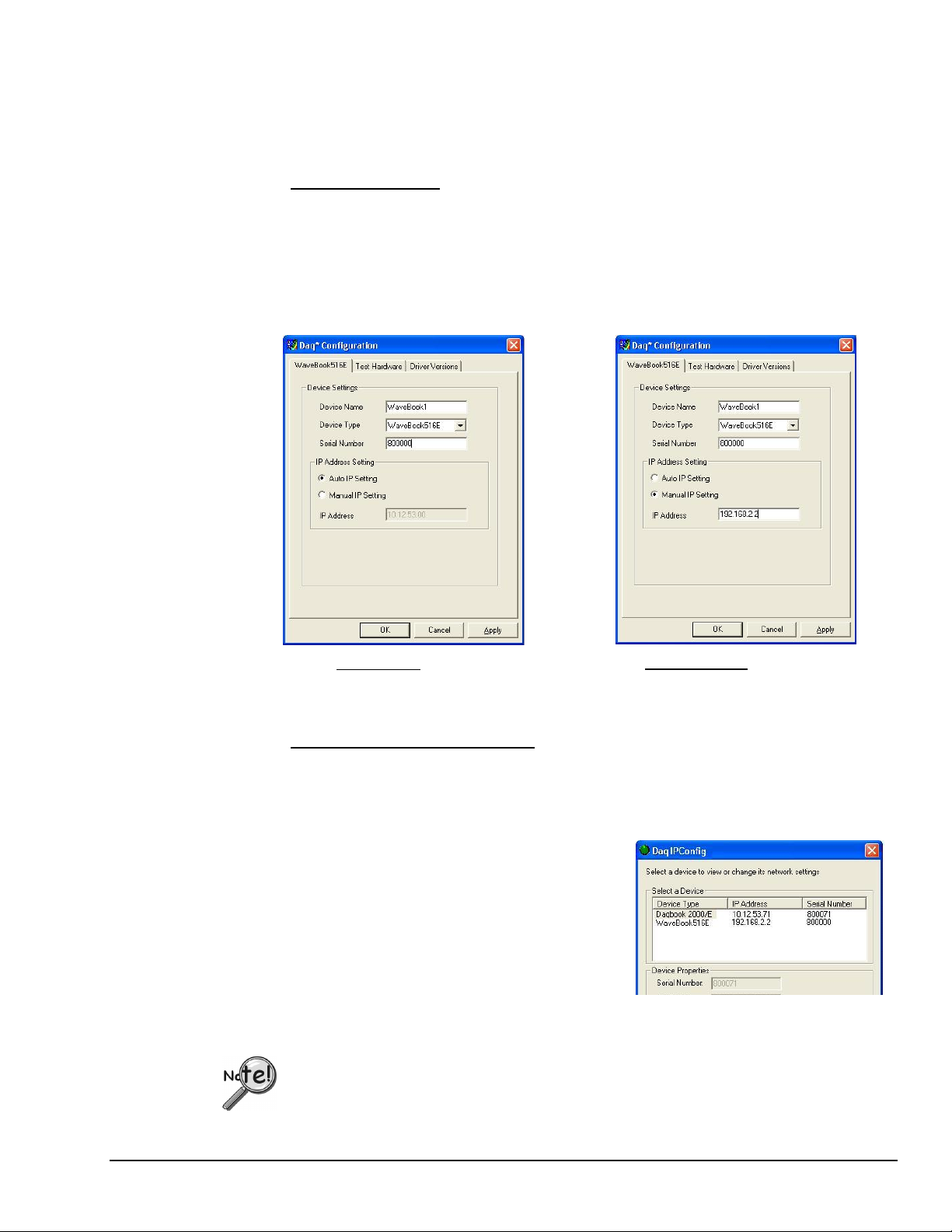
3. Set the properties of the first-level device.
In this step you will set the device properties according to one of the following two methods, depending on
whether you have a “Dedicated Network” or a “LAN with DHCP Server Network.” Illustrations of the
network types are provided on page B-3.
Users of Dedicated Networks
a. Enter the Serial Number of the first-level device (DaqBook/2000E, or WaveBook/516E). In
the following screen shots the Serial Number is 800000.
b. Select the “Auto IP Setting” radio button. Note that the IP Address of the DaqBook/2000E,
or the WaveBook/516E will automatically be calculated and displayed in the IP Address field
as indicated in the following left-hand figure.
c. Click the <OK> button.
follow these 2 steps.
For DEDICATED Networks
For LAN with DHCP Server Networks
Daq* Configuration, Properties Dialog Boxes
: The above images are based on WaveBook/516E. We could similarly have DaqBook/2000E selected.
Note
Users of LAN with DHCP Server Networks
follow these 3 steps.
The DaqIPConfig applet provides the Serial Number and the IP Address of the device. Users of LAN
with DHCP Server Networks will need to enter both numbers in the Daq* Configuration, Properties
dialog boxes (previous right-hand figure). Page B-9 includes instructions for accessing DaqIPConfig.
If needed, refer to the upper right-hand figure in regard to radio-button and data entry locations.
a. Enter the base 10 version of the Serial Number
of the DaqBook/2000E or WaveBook/516E,
as applicable.
b. Select the “Manual IP Setting” radio button.
c. In the IP Address field, enter the IP address.
d. Click the <OK> button.
Partial View of DaqIP Config
Showing IP Addresses & Serial Numbers
Provide your network administrator with the information on the device’s MAC label.
Also, find out from the administrator if the IP Address will be changing. If so, see if you
can obtain a permanent IP Address dedicated specifically to your device.
Installation Guide / Section B
927796
Connecting a DaqBook/2000E or WaveBook/516E to the Ethernet IG / B-11
Page 26

4. Test the system connections.
a. Make sure the device has been properly installed and is powered-on.
b. Make sure all cables are properly and securely connected.
c. Click the “Test Hardware” tab.
d. Click the <TCP/IP Test> button. This tests the Transmission Control Protocol / Internet
Protocol.
The TCP/IP
test results have two components: Pinging Device and TCP Connection.
Appendix G, TCP/IP and Resource Tests, includes a brief explanation of each.
e. Upon completion of the TCP/IP test, click the <Resource Test> button.
The Resource Test
consists of two components: Resource Tests and Performance Tests.
Appendix G, TCP/IP and Resource Tests, includes a brief explanation of each.
When testing a WaveBook or DaqBook device, if the unit does not respond within 30
seconds perform the following steps:
1) reboot the system
2) upon power-up, re-open the Daq* Configuration applet
3) select another configuration setting
4) reinitiate the test
This completes the procedure for connecting a DaqBook/2000E or WaveBook/516E to the Ethernet. At this
point you should refer to other sections of the manual, e.g., pinouts, information on system expansion, and
data acquisition.
Reference Notes:
Depending on your application and system setup, related information can be found in the
following sources:
➣
The DBK Options Manual (p/n 457-0905).
➣
The WBK Options Manual (p/n 489-0902).
➣
The Programmer’s Manual, (p/n 1008-0901).
Note: You can access PDF documents directly from the opening screen of the data acquisition CD
via the <View PDFs> button.
IG / B-12 Connecting a DaqBook/2000E or WaveBook/516E to the Ethernet
927896
Installation Guide / Section B
Page 27
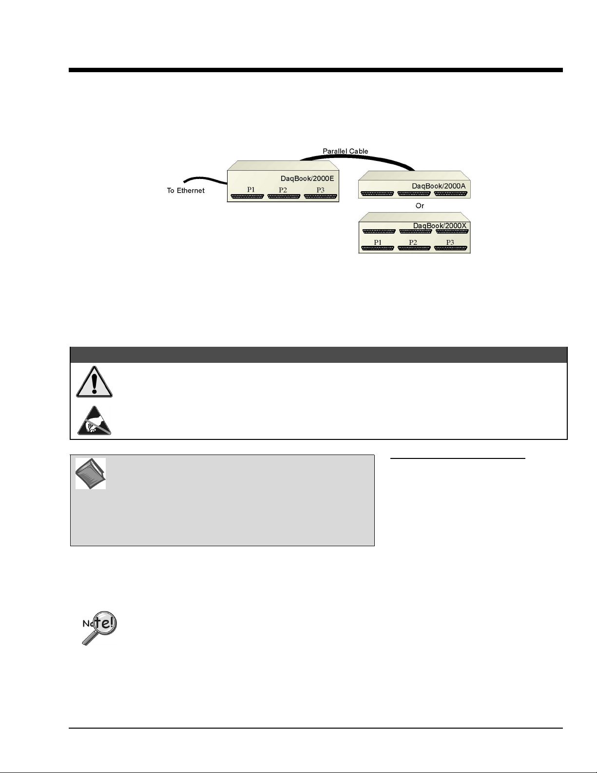
Section C
Connecting a DaqBook/2000A or DaqBook/2000X to a DaqBook/2000E
Connecting a DaqBook/2000A or a DaqBook/2000X
to a DaqBook/2000E
CAUTION
Turn off power to the system devices and externally connected equipment before connecting cables.
Electric shock or damage to equipment can result even under low-voltage conditions.
Take ESD precautions (packaging, proper handling, grounded wrist strap, etc.)
Minimum System Requirements
Reference Note: Adobe PDF versions of user manuals will
automatically install onto your hard drive as a part of product
support. The default location is in the Programs group, which
can be accessed from the Windows Desktop. You can also
access documents directly from the data acquisition CD via the
<View PDFs> button located on the CD’s opening screen.
PC system with Pentium® Processor
Windows Operating System
RAM, as follows:
32 Mbytes of RAM for Windows 95/98/NT
64 Mbytes of RAM for Windows Me
64 Mbytes of RAM for Windows 2000
64 Mbytes of RAM for Windows XP
In this section we are dealing with a setup in which: (1) the DaqBook/2000E is already connected to the
Ethernet, and (2) the associated software from the data acquisition CD is installed.
Installation Guide / Section C
927696
Connecting a DaqBook/2000A or /2000X to a DaqBook/2000E IG / C-1
Page 28
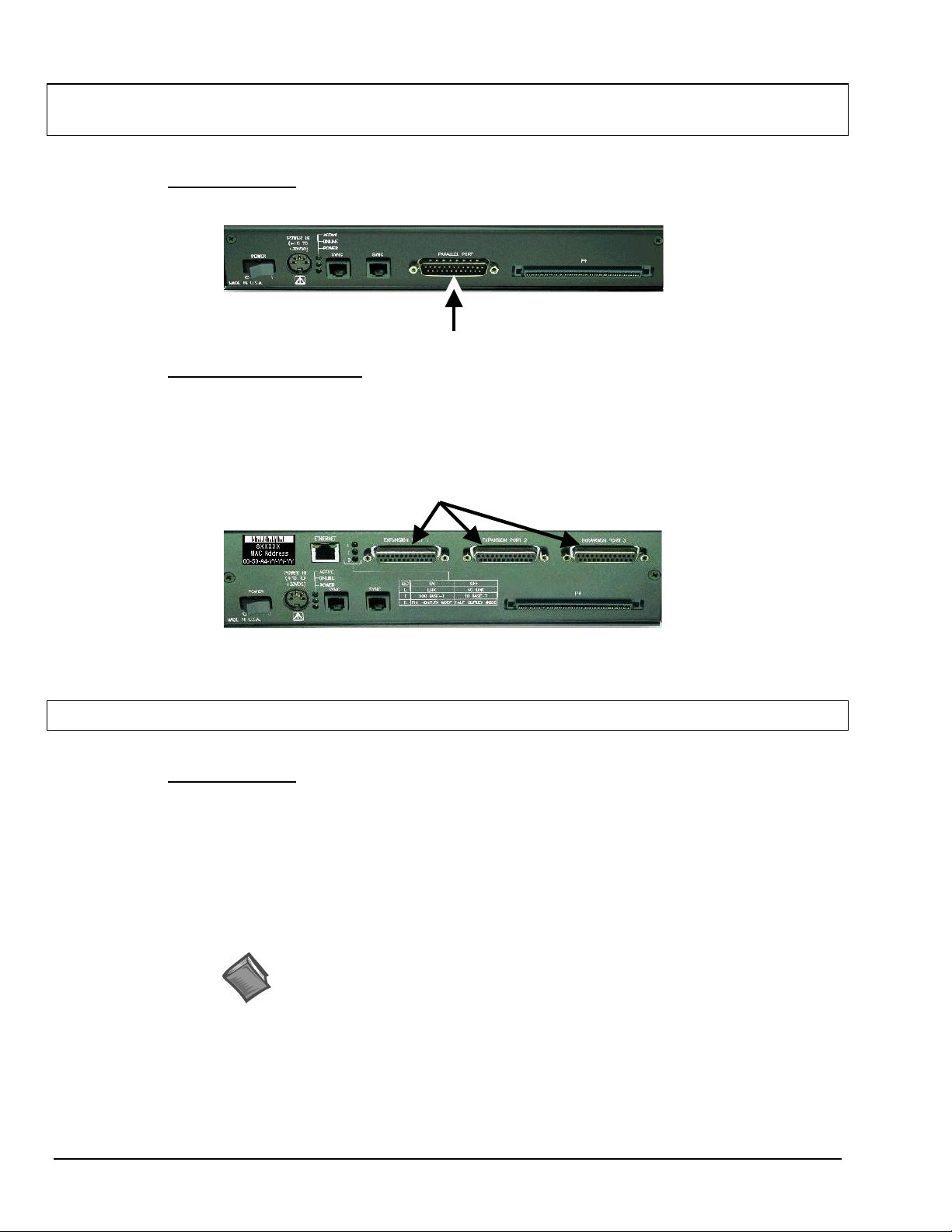
STEP C.1 –
Connect the DaqBook/2000A or DaqBook/2000X to an Expansion Port on
the DaqBook/2000E
What you will need
One parallel port cable, e.g. a CA-35-2 (2-foot) or a CA-35-12 (1-foot) cable.
How to make the connection:
1. Place the DaqBook/2000E power switch in the “OFF” (0) position, if it is not already OFF.
2. Connect the parallel port cable to the parallel port connector on the rear panel of the
DaqBook/2000A or DaqBook/2000X. See the preceding picture.
Connect the other end of the cable to one of three expansion ports on the DaqBook/2000E.
3.
:
DB25 Parallel Port Connector
Expansion Ports
STEP C.2 –
DaqBook/2000E
Connect the DaqBook/2000A or DaqBook/2000X to Power
What you will need
A power supply with a range of +10 VDC to +30 VDC.
The power supply needs to have a male DIN5 connector.
Note: The switching-mode power supply that is commonly used with DaqBook/2000 Series
Note: Various AC adapter models support power grids of USA, Europe, Japan, and Asia.
:
systems has an input range of 100 VAC to 240 VAC at 50 Hz to 60 Hz. The power
supply’s output [to the DaqBook/2000 Series device] is 15 VDC @ 2.7 amps via a DIN5
connector.
Reference Note: It is possible to use a VDC power source other than the commonly
used switching-mode power supply, often referred to as an adapter. However, be sure
to consult the power-related sections of DBK Basics before doing so. The DBK Basics
segment immediately follows chapter 1 of this user’s manual.
IG / C-2 Connecting a DaqBook/2000A or /2000X to a DaqBook/2000E
927696
Installation Guide / Section C
Page 29
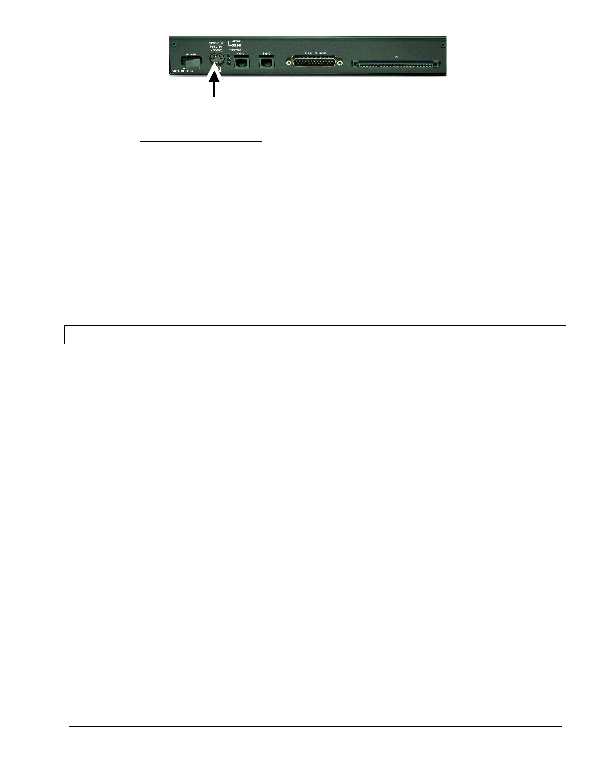
DIN5 POWER IN Connector (+10 to +30 VDC)
How to make the connection:
1. Place the DaqBook/2000A or DaqBook/2000X power switch in the “OFF” (0) position, if it is
not already OFF.
2. Connect the DIN5 end of the adapter’s cable to the power in connector on the DaqBook/2000A
or DaqBook/2000X (see preceding figure).
3. Connect the adapter’s plug to a standard AC outlet.
4. If your adapter has a power switch, position it to “ON.”
T
urn ON the DaqBook/2000A or DaqBook/2000X by placing the unit’s power switch to the
5.
“1” position. The power led will light up.
T
urn the DaqBook/2000E “ON” by placing the unit’s power switch to the “1” position.
6.
The power led will light up.
STEP C.3 –
The Daq* Configuration applet, designed for 32-bit Windows 95/98/Me/NT/2000/XP systems, is located in the
Windows Control Panel. It allows you to add or remove a device and change configuration settings. The
included test utility provides feedback on the validity of current configuration settings, as well as performance
summaries.
1. Open the Daq* Configuration Applet.
2. Add the DaqBook/2000A or DaqBook/2000X.
Configure and Test the Hardware
a. Open the Control Panel by navigating from the Windows’ Desktop as follows:
Start Menu ⇒ Settings ⇒ Control Panel
b. From the Control Panel, double-click the Daq* Configuration icon.
In the Daq Configuration applet, add the DaqBook/2000A or DaqBook/2000X to one of the three
expansion ports of the DaqBook/2000E.
a. Select the DaqBook/2000E in the Device Inventory configuration tree (see following figure).
b. Click the <Add Device> button. The “Select Device Type” box will appear.
c. Select “DaqBook2000A/2000X” from the list of devices.
d. Click the <OK> button. The “Properties” box for the device will appear.
Installation Guide / Section C
927696
Connecting a DaqBook/2000A or /2000X to a DaqBook/2000E IG / C-3
Page 30
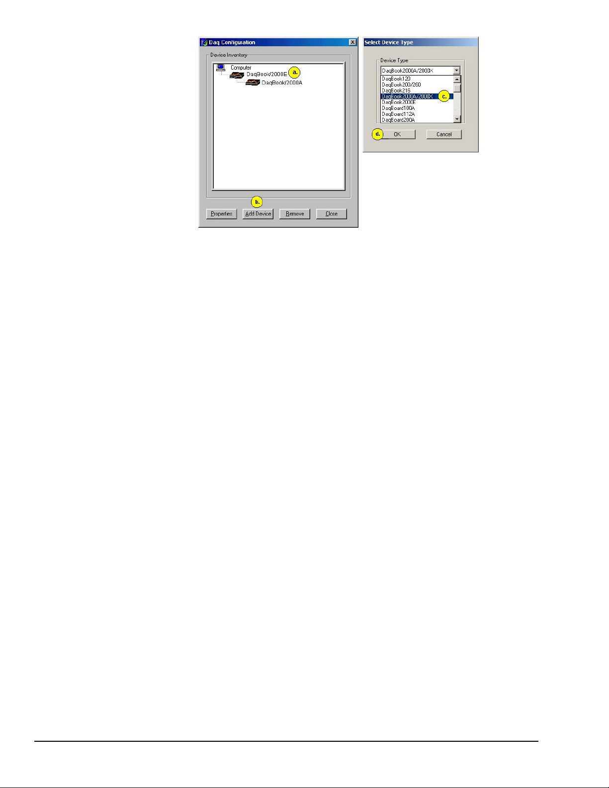
Adding a DaqBook/2000A to a DaqBook/2000E
Note: Devices have default names, for example, DaqBook2K0. If desired, you can change the device name.
IG / C-4 Connecting a DaqBook/2000A or /2000X to a DaqBook/2000E
927696
Installation Guide / Section C
Page 31
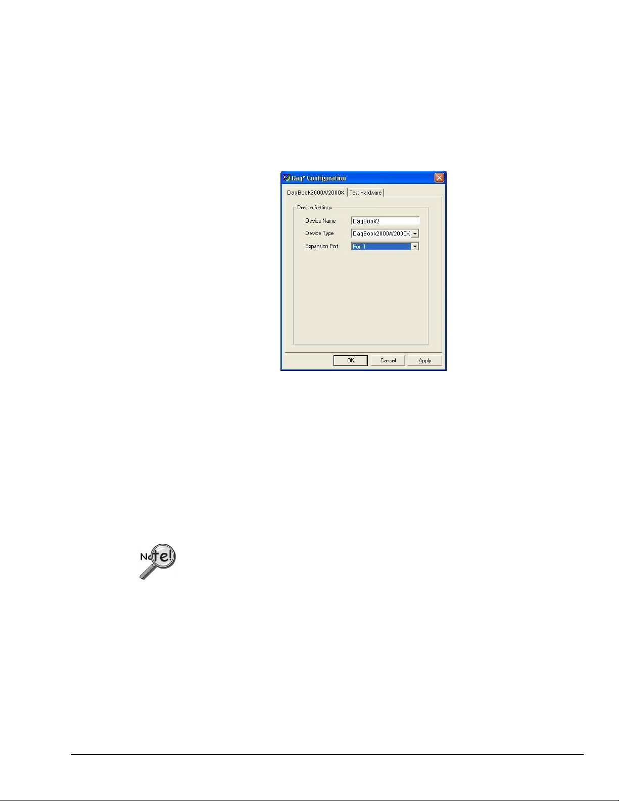
3. Set the Expansion Port number.
In our current setup, the DaqBook/2000A (or DaqBook/2000X) is a second-level device. This is because it
is connected to an expansion port of a first-level device, i.e., the DaqBook/2000E.
For this step select the expansion port number to which the DaqBook/2000A or DaqBook/2000X is
connected, i.e., Port 1, Port 2, or Port 3.
Note: The DaqBook/2000A and DaqBook/2000X make use of the same IP address as the DaqBook/2000E
to which they are connected. For this reason no configuration of the IP address is called for in the
second-level device’s properties box.
Setting the Expansion Port Number
4. Test the system connections.
a. Make sure the device has been properly installed and is powered-on.
b. Make sure all cables are properly and securely connected.
c. Click the “Test Hardware” tab.
d. Click the <Resource Test> button.
Appendix G, TCP/IP and Resource Tests, includes a brief explanation of the test.
Testing the DaqBook/2000 Series device may, in some cases, cause the system to hang.
If test results are not displayed in 30 seconds or the system does not seem to be responding,
reboot the system. Upon power-up, re-enter the Daq Configuration and change the
DaqBook/2000 Series device configuration settings to those that work properly.
This completes the instructions for connecting a DaqBook/2000A or DaqBook/2000X to a
DaqBook/2000E. At this point you should refer to other sections of the manual, e.g., pinouts,
information on system expansion, and data acquisition.
Installation Guide / Section C
927696
Connecting a DaqBook/2000A or /2000X to a DaqBook/2000E IG / C-5
Page 32

Reference Notes:
➣
If you experience difficulties, please consult the additional user documentation before calling
technical support. User documentation is included on your data acquisition CD, and is installed
automatically as a part of product support, when your software is installed. The default location is
the Programs Group. The documentation includes API information, pinouts, troubleshooting, and a
great deal of material regarding specific DBK cards and modules.
➣
Documents can be read directly from the data acquisition CD via the <View PDFs> button located
on the opening screen.
For DaqBook/2000 Series Ethernet Applications:
When powering up a DaqBook/2000 Series system it is important that the DaqBook/2000E is
powered last, and that the most remote system components are powered first. Other power-up
sequences will result in software’s failure to recognize all components.*
First, power-on the DBK expansion modules.
•
Second, power-on the DaqBook/2000A, DaqBook/2000X, or DBK modules that are connected
•
to the expansion ports of the DaqBook/2000E.
Finally, power-on the DaqBook/2000E.
•
An exception to this power-up scheme is to power-on the entire system at once.
*
IG / C-6 Connecting a DaqBook/2000A or /2000X to a DaqBook/2000E
927696
Installation Guide / Section C
Page 33
Appendix D – Device Connector Reference D
For DaqBook/2000 Series Devices
DaqBook/2000A …… D-1
DaqBook/2000X …… D-3
DaqBook/2000E …… D-5
DaqBook/2000A
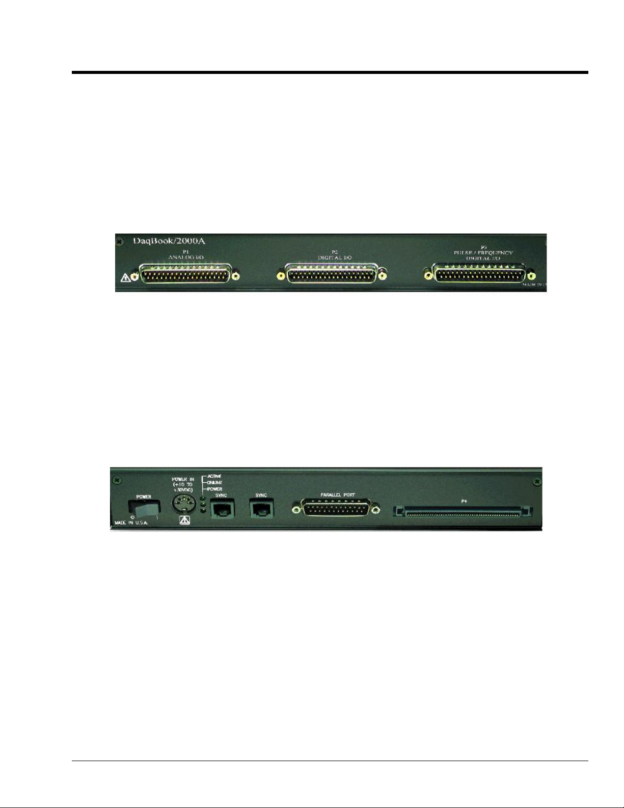
Front Panel
The DaqBook/2000A’s front panel offers three DB37 connectors designated as P1, P2, and P3.
P1 connects to Analog I/O.
P2 connects to Digital I/O.
P3 connects to Pulse / Frequency Digital I/O.
Pinouts of each immediately follow Appendix G of this installation guide.
Rear Panel
DaqBook/2000A’s rear panel contains a power switch, DIN5 power connector, LEDs, synchronization
ports, a parallel port connector, and a 100-pin (P4) connector. Additional detail follows. Items
described below are done so from left to right, when looking at the rear panel.
POWER Switch: A rocker-type switch with a “0” label for Power Off, and a “1” for Power On.
POWER IN: +10 to +30 VDC, through a socket type DIN5 connector on the chassis.
Power is typically supplied from a TR40U power adapter.
LEDs: ACTIVE – Lights when a sample has been converted by the A/D Converter.
ONLINE – Lights when software establishes communication to the unit.
POWER – Lights when power is turned on and is present.
SYNC (Qty of 2) – Two “synchronization ports” provide a means of synchronizing multiple
DaqBook/2000 Series units in regard to post-trigger scanning. The ports accept CA-74-1 and CA-74-5
RJ-11, 6 conductor type cables.
Parallel Port – A DB25 connector used to connect theDaqBook/2000A to the Parallel Port of the host
PC, or to an Expansion Port of a DaqBook/2000E, or to an Expansion Port of a WBK25 Ethernet
Interface Module. Applicable cables are CA-35-2 (2-foot) and CA-35-12 (1-foot).
Installation Guide / Appendix D
977296
Device Connector Reference IG / D-1
Page 34
P4 – P4 is a 100-pin connector that shares signal connections with the P1, P2, and P3 connectors. P4
offers no additional I/O. You can connect a DBK200 Series Option to P4 via a CA-195 cable to
essentially distance the P1, P2, P3 connection from the DaqBook/2000A. See the following Caution.
CAUTION
Signal conflicts between a DaqBook/2000 Series device’s P1, P2, P3 connectors and its
P4 connector can result in erroneous readings and possible equipment damage.
Therefore, when connections have been made to P1, P2, and/or P3, use caution when
making connections through P4, and visa versa.
Use a CA-209D CE Cable Kit in electrically noisy environments. The kit includes a
3-foot long shielded cable, two grounding pigtails, two cable clamps, and 4 screws. The
CE Compliance chapter provides additional information.
Reference Note: The document section entitled, System Connections and Pinouts, includes
pinouts for P1, P2, P3 and P4. The section immediately follows Appendix G of this
installation guide.
IG / D-2 Device Connector Reference
977296
Installation Guide / Appendix D
Page 35
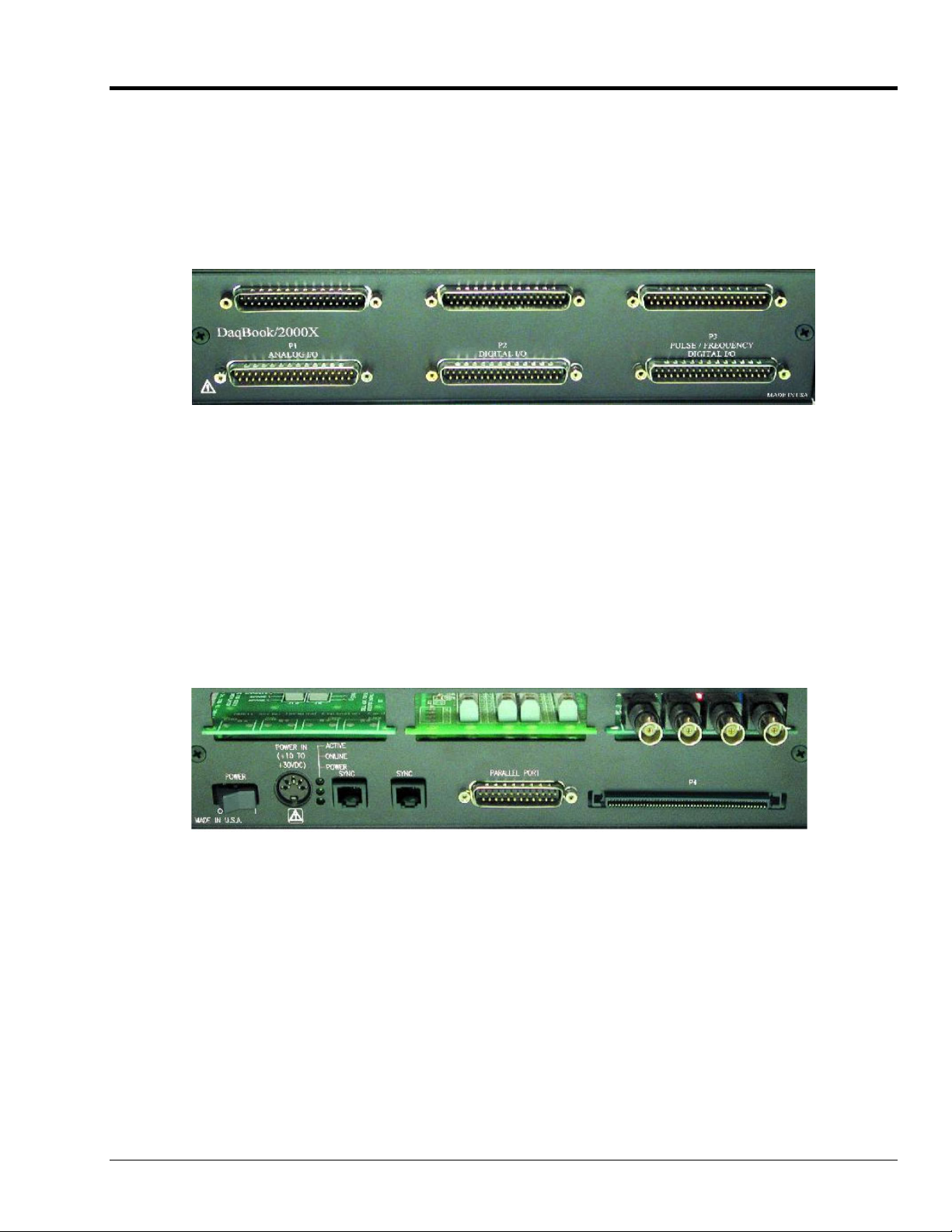
DaqBook/2000X
Front Panel
The upper row of theDaqBook/2000X front panel contains port openings for three installed DBK cards.
In the following figure, each connector seen in the upper row belongs to an installed DBK card.
Appendix E, System Expansion, contains a section entitled Expansion via DBK Cards in a
DaqBook/2000X. The section includes one system example in which 3 analog DBK cards are used, and
another in which 1 analog DBK card and 2 digital DBK cards are used.
The lower row of the DaqBook/2000X front panel offers three DB37 connectors designated as P1, P2,
and P3.
P1 connects to Analog I/O.
P2 connects to Digital I/O.
P3 connects to Pulse / Frequency Digital I/O.
Pinouts of each immediately follow Appendix G of this installation guide.
Rear Panel
The DaqBook/2000X rear panel contains an upper section of 3 card slots and a lower section, which
includes a power switch, DIN5 power connector, LEDs, synchronization ports, a parallel port connector,
and a 100-pin (P4) connector. Items described below are done so from left to right. The top row,
consisting of three expansion slots, is listed first.
Expansion Cards - Up to three can be added, one per card slot.
POWER Switch: A rocker-type switch with a “0” label for Power Off, and a “1” for Power On.
POWER IN: +10 to +30 VDC, through a socket type DIN5 connector on the chassis.
Power is typically supplied from a TR40U power adapter.
LEDs: ACTIVE – Lights when a sample has been converted by the A/D Converter.
ONLINE – Lights when software establishes communication to the unit.
POWER – Lights when power is turned on and is present.
SYNC – Two “synchronization ports” provide a means of synchronizing multiple DaqBook/2000 Series
units in regard to post-trigger scanning. The ports accept CA-74-1 and CA-74-5 RJ-11, 6 conductor
type cables.
Parallel Port – A DB25 connector used to connect theDaqBook/2000X to the parallel port of the host
PC or to the EXPANSION PORT of a DaqBook/2000E. Applicable cables are CA-35-2 (2-foot) and
CA-35-12 (1-foot).
P4 – P4 is a 100-pin connector that shares signal connections with the P1, P2, and P3 connectors. P4
offers no additional I/O. You can connect a DBK200 Series Option to P4 via a CA-195 cable to
essentially distance the P1, P2, P3 connection from the DaqBook/2000X. See the following Caution.
Installation Guide / Appendix D
977296
Device Connector Reference IG / D-3
Page 36
CAUTION
Signal conflicts between a DaqBook/2000 Series device’s P1, P2, P3 connectors and its
P4 connector can result in erroneous readings and possible equipment damage.
Therefore, when connections have been made to P1, P2, and/or P3, use caution when
making connections through P4, and visa versa.
Use a CA-209D CE Cable Kit in electrically noisy environments. The kit includes a
3-foot long shielded cable, two grounding pigtails, two cable clamps, and 4 screws. The
CE Compliance chapter provides additional information.
Reference Note: The document section entitled, System Connections and Pinouts, includes
pinouts for P1, P2, P3 and P4. The section immediately follows Appendix G of this
installation guide.
IG / D-4 Device Connector Reference
977296
Installation Guide / Appendix D
Page 37
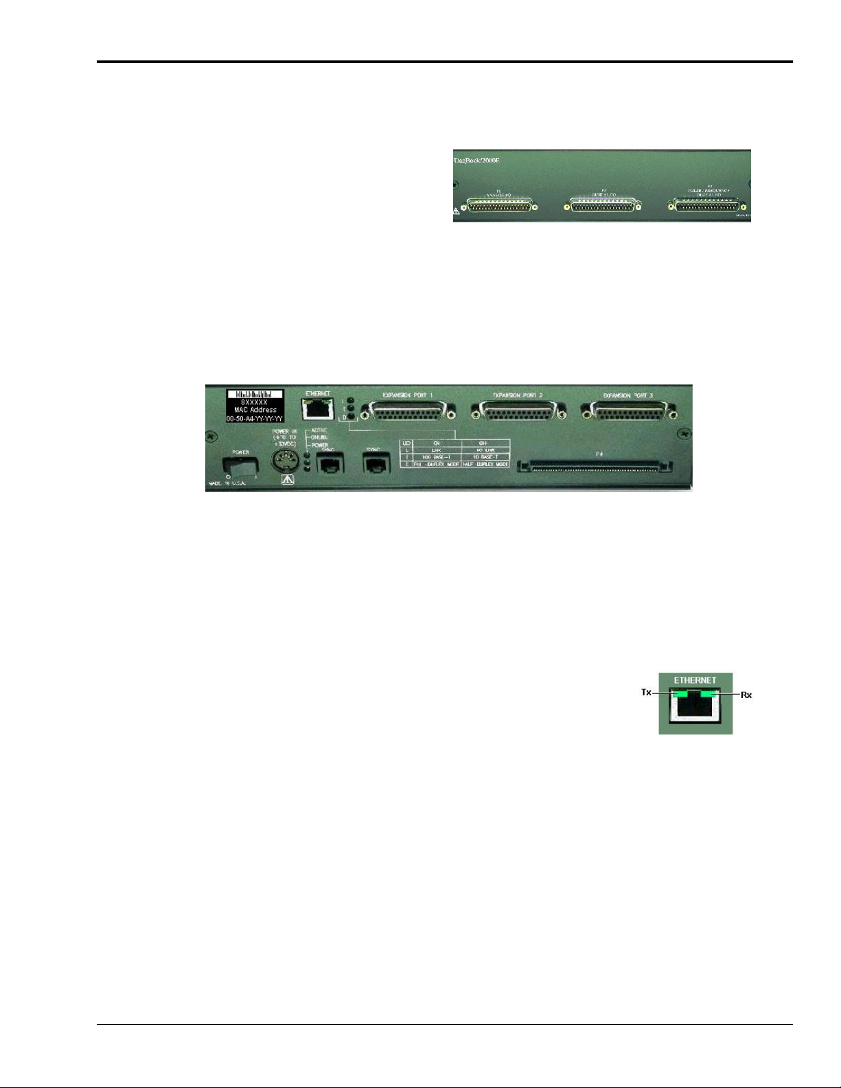
DaqBook/2000E
Front Panel
The DaqBook/2000E’s front panel offers three
DB37 connectors designated as P1, P2, and P3.
P1 connects to Analog I/O.
P2 connects to Digital I/O.
P3 connects to Pulse / Frequency Digital I/O.
Pinouts of each immediately follow Appendix G of this installation guide.
Rear Panel
The upper row of DaqBook/2000E’s rear panel contains a MAC Address Label, Ethernet Port, 5 LEDs,
and three expansion ports. The lower section of the panel includes a power switch, DIN5 power connector,
3 LEDs, 2 synchronization ports, and 100-pin (P4) connector. Items described below are done so from left
to right, with the top row discussed first.
MAC Address Label: The Media Access Control (MAC) label is located in the upper left corner of the
rear panel. The label shows the device serial number in three formats: (1) Barcode, (2) base 10, and
(3) hexadecimal. If prompted to enter a serial number in software, use the base 10 number. Conversion to
a hexadecimal number for use in addressing will be automatic.
ETHERNET: The 10/100BaseT Ethernet port can connect to the Ethernet port of the host PC, or to an
Ethernet network. Either of two Ethernet patch cables may be used to make the connection. CA-242 is a
1.5 foot cable. CA-242-7 is a 7-foot cable. Note that the Ethernet connector has two built in LEDs that
indicate traffic flow. These are discussed with the three other Ethernet-related LEDs. Note that the
Ethernet cable length must be <10m in order for the system to be CE Compliant.
LEDs: There are 5 ETHERNET Status LEDS. Two rectangular LEDs, Tx and Rx
are built right into the frame of the Ethernet jack. The other three, located
just to the right of the jack, are round and are labeled L, T, and D.
Tx – “ON” indicates traffic is being transmitted (see figure at right).
Rx – “ON” indicates that the port is receiving traffic.
L (Link) “ON” indicates a link exists. “OFF” indicates no link.
T (Transmit) “ON” indicates 100 M-Bits, “OFF” indicates 10 M-Bits.
D (Duplex) “ON” indicates full duplex, which allows simultaneous two-
way data traffic. “OFF” indicates half-duplex, which only allows
one-way data traffic at any given time.
EXPANSION PORTS [1, 2, and 3]: used to expand the system with up to three additional devices. These
are used to connect the DaqBook/2000E to the PARALLEL PORT connector of DaqBook/2000A and
DaqBook/2000X units.
POWER Switch: A rocker-type switch with a “0” label for Power Off, and a “1” for Power On.
POWER IN: +10 to +30 VDC, through a socket type DIN5 connector on the chassis. Power is typically
supplied from a TR40U power adapter.
Installation Guide / Appendix D
977296
Tx and Rx LEDs
Device Connector Reference IG / D-5
Page 38
LEDs: ACTIVE – Lights when a sample has been converted by the A/D Converter.
ONLINE – Lights when the DaqBook/2000E’s internal Ethernet module establishes communication
to the unit.
POWER – Lights when power is turned on and is present.
SYNC (Qty 2) – Two “synchronization ports” provide a means of synchronizing multiple DaqBook/2000
Series units in regard to post-trigger scanning. The ports accept CA-74-1 and CA-74-5 RJ-11, 6 conductor
type cables.
P4 – P4 is a 100-pin connector that shares signal connections with the P1, P2, and P3 connectors. P4
offers no additional I/O. You can connect a DBK200 Series Option to P4 via a CA-195 cable to essentially
distance the P1, P2, P3 connection from the DaqBook/2000E. See the following Caution.
CAUTION
Signal conflicts between a DaqBook/2000 Series device’s P1, P2, P3 connectors and its
P4 connector can result in erroneous readings and possible equipment damage.
Therefore, when connections have been made to P1, P2, and/or P3, use caution when
making connections through P4, and visa versa.
Use a CA-209D CE Cable Kit in electrically noisy environments. The kit includes a
3-foot long shielded cable, two grounding pigtails, two cable clamps, and 4 screws. The
CE Compliance chapter provides additional information.
Reference Note: The document section entitled, System Connections and Pinouts, includes
pinouts for P1, P2, P3 and P4. The section immediately follows Appendix G of this installation
guide.
IG / D-6 Device Connector Reference
977296
Installation Guide / Appendix D
Page 39
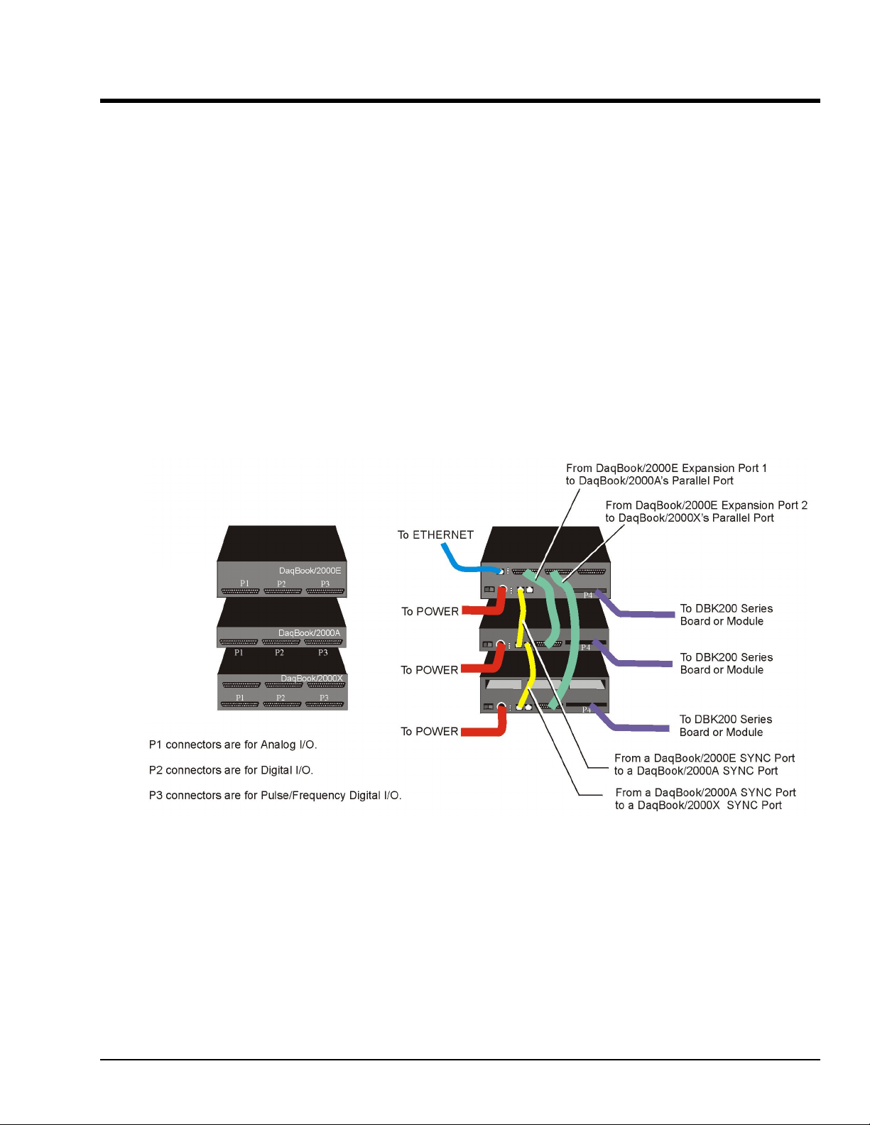
Appendix E – System Expansion E
Expansion via Additional DaqBook/2000 Series Devices …… E-1
Expansion via a WBK25 Ethernet Interface Module …… E-2
Expansion via DBK Modules (3 examples) …… E-3
Expansion via DBK Cards in a DaqBook/2000X (2 examples) …… E-7
How to Mount One Module to Another …… E-8
Using T-Cables …… E-9
Note: If you are not familiar with the connectors of the DaqBook/2000 Series devices, please review
Appendix D, Device Connector Reference before proceeding.
Expansion via Additional DaqBook/2000 Series Devices
The following figure represents only one of many possibly system configurations.
DaqBook/2000E
DaqBook/2000A
DaqBook/2000X
Possible DaqBook/2000 System Using /2000E, /2000A, and /2000X Units
Installation Guide / Appendix E
927696
System Expansion IG / E-1
Page 40
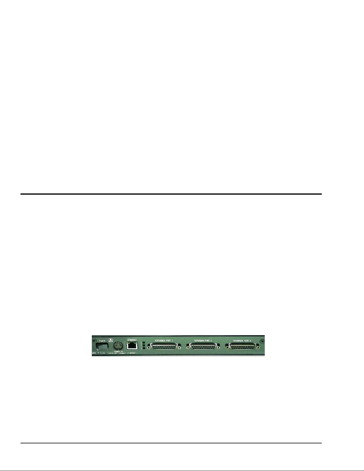
Ports and Cables for Expansion, Synchronization, and Ethernet Connection
Expansion
Expansion Port Cables are used when up to three DaqBook/2000 Series devices are to be connected to a
DaqBook/2000E via its expansion ports. The expansion port cables are the communication links that
stream acquired data back to the DaqBook/2000E and to the host PC. Note that the expansion units need
not be of the same type. Cables CA-35-2 (2-foot) and CA-35-12 (1-foot) have been approved for use as
expansion port cables.
Synchronization
SYNC Cables can be used to make several DaqBook/2000 Series devices, which are linked to each other,
scan-synchronous. Cables that have been approved for use in synchronizing DaqBook/2000 Series devices
are CA-74-1 (1-foot) and CA-74-5 (5-foot). When scan-synchronization is employed, one of the
DaqBook/2000 Series devices will be programmed as the “master.” This unit drives the acquisition timing
of the “slave” units. The chapter 1 section entitled Synchronous I/O Operations contains additional
information.
Ethernet Connection
Ethernet Cables intended for use with DaqBook/2000 Series devices are CA-242 (a 1.5 foot cable) and
CA-242-7 (a 7 foot cable). DaqBook/2000E can connect directly to an Ethernet port on a PC or network
hub via either cable. DaqBook/2000A and DaqBook/2000X are connected to the Ethernet when interfaced
with a DaqBook/2000E [which is connected to the Ethernet] or when connected to a WBK25 Ethernet
Interface Module. In both scenarios the DB25 Parallel Port of the DaqBook/2000A (or /2000X) device is
connected to one of three Expansion Ports located on the DaqBook/2000E [or on the WBK25]. The
connection would be made with a CA-35-2 (2-foot) or a CA-35-12 (1-foot) cable.
Expansion via a WBK25 Ethernet Interface Module
The WBK25 is a high-speed Ethernet-to-parallel port interface module. The device includes one
10/100BaseT Ethernet port for connecting to a PC Ethernet Port or Ethernet network hub. It also includes
three parallel ports, designated as “expansion ports.” Parallel cables connected to these ports can be
attached to any model of WaveBook, DaqBook, WBK40 Series option, or any combination of up to 3 of
these devices. Note that these parallel ports cannot be used to connect to auxiliary devices such as printers
and scanners.
Data transfer rates with the WBK25 depend on the network to which it is attached. If the WBK25 is used
with DaqBook/2000 Series device and WBK40 series options, then up to three of these devices can be
attached to one WBK25 and are able to transfer data at the maximum sampling rates on all three devices
simultaneously.
If the WBK25 is attached to a shared Ethernet network, then data transfer rates will be dependent on the
other network traffic at the time. It is not possible to guarantee maximum data transfer rates in this mode.
It is also possible to attach multiple WBK25 units to one PC having multiple Ethernet ports, or having a
multi-port Ethernet hub. Performance under these conditions will be dependent on the PC’s ability to
handle multiple networks.
WBK25 Ethernet-to-Parallel Port Interface
You can connect a DaqBook/2000A or a DaqBook/2000X to the Ethernet via a WBK25 Ethernet Interface
Module. To do so, the DB25 Parallel Port of a DaqBook/2000A (or /2000X) device is connected to one of
the three Expansion Ports located on the WBK25. The connection would be made with a CA-35-2 (2-foot)
or a CA-35-12 (1-foot) cable. Two additional DaqBook/2000 Series units could be connected to via the
remaining two expansion ports. These connections would also be made via a CA-35-2 or CA-35-12
cables.
The WBK25 connects directly to an Ethernet port on a PC or network hub, via the unit’s built-in
10/100BaseT Ethernet interface. An Ethernet patch cable CA-242 (1.5 foot) or CA-242-7 (7 foot) cable
is used to make the connection.
IG / E-2 System Expansion
927696
Installation Guide / Appendix E
Page 41
DaqBook/2000A
DaqBook/2000A
DaqBook/2000A
WBK25
Channel Input Side Device Interface Side
To ETHERNET To POWER
DaqBook/2000A
DaqBook/2000A
WBK25
DaqBook/2000A
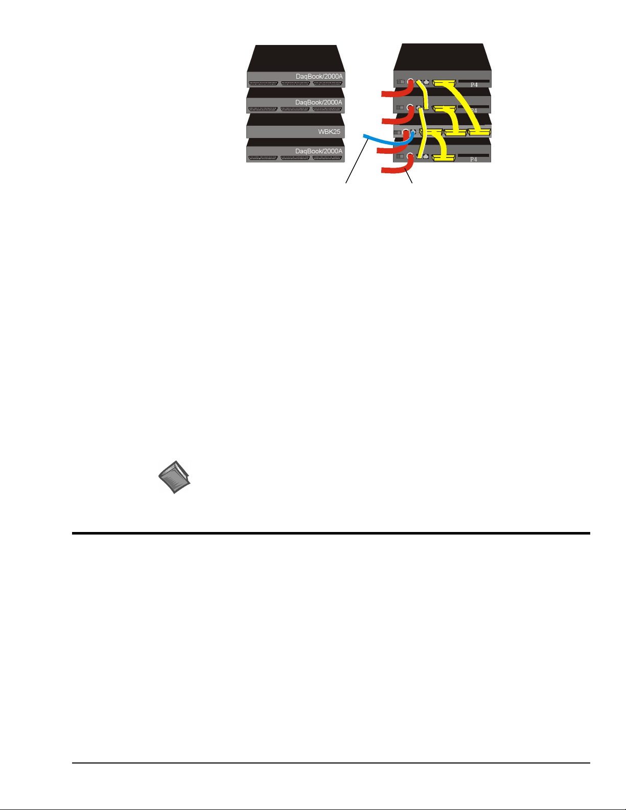
System with WBK25 Interface and 3 DaqBook/2000A Devices
Lines and Cables Used in the WBK25 Interface Example [Device Interface Side Only]:
1. Power Supply - To each DaqBook/2000A POWER IN DIN 5 connector, +10 VDC to +30 VDC,
and to the WBK25; typically from a TR40U power adapter.
2. From the bottom DaqBook/2000A’s PARALLEL PORT connector to EXPANSION PORT 1 on the
WBK25 Ethernet Interface Module. A CA-35-2 (2-foot) or CA-35-12 (1-foot) cable is used for this
connection.
3. From either of two SYNC Ports on the bottom DaqBook/2000A to either of two SYNC Ports on the
next DaqBook/2000A. Cable CA-74-1 (1-foot) or CA-74-5 (5-foot) is used for this connection.
4. From the available SYNC Port on the second DaqBook/2000A to either of two SYNC Ports on the
upper DaqBook/2000A. Cable CA-74-1 (1-foot) or CA-74-5 (5-foot) is used for this connection.
5. From the WBK25’s EXPANSION PORT 2 to the second DaqBook/2000A’s Parallel Port.
A CA-35-2 (2-foot) or CA-35-12 (1-foot) cable is used for this connection.
6. From the WBK25’s EXPANSION PORT 3 to the third DaqBook/2000A’s Parallel Port.
A CA-35-2 (2-foot) or CA-35-12 (1-foot) cable is used for this connection.
Reference Note:
The WBK25 Ethernet-to-Parallel Port Interface is shipped with a user’s guide
(p/n 489-0903). Refer to that document for instructions regarding how to connect
a WBK25 to the Ethernet.
Expansion via DBK Modules
This section consists of three system examples, each having a figure and a corresponding list of “cables
used.”
Note that the figures and tables illustrate primary device connections to each other, they do not show
signal, power, Ethernet, or PC connections. These other types of connections are discussed elsewhere in
the document.
In regard to power, note that DaqBook/2000 Series devices can provide 15000 mW of power. This means
that many system configurations will not require additional power modules. However, to avoid the
possibility of inadequate power, you should always check power management tables prior to putting an
acquisition system together.
In regard to physically stacking modules, i.e., attaching one module to another, fastener Panels, sometimes
referred to as “splice plates,” (p/n 262-0801) are typically used. Optional handles (p/n HA-111) may also
be attached to a system.
Installation Guide / Appendix E
927696
System Expansion IG / E-3
Page 42
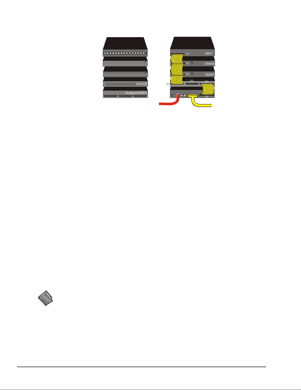
Example 1: DaqBook/2000A with a DBK1, two DBK84 Modules, and DBK203
DBK1
DBK84
DBK84
(Note 2)
DBK203
DaqBook/2000A
To POWER To PC or to /2000E
Channel Input Side Device Interface Side
DaqBook/2000A System
with a DBK1, two DBK84 Modules, and DBK203
Lines and Cables Used in Example 1 [Device Interface Side Only]:
1. Power Supply - To the DaqBook/2000A POWER IN DIN 5 connector, +10 VDC to +30 VDC,
typically from a TR40U power adapter.
2. From the DaqBook/2000A PARALLEL PORT connector, via a CA-35-x cable, to either
(a) the host PC’s PARALLEL PORT, or
(b) one of three DaqBook/2000E EXPANSION PORTS
(c) one of three WBK25 EXPANSION PORTS
DBK1
DBK84
DBK84
DBK203
(Note 2)
DaqBook/2000A
3. From DaqBook/2000A’s P4 connector to DBK203’s P4 connector, via a CA-195-1 cable.
4. From DBK203’s P1 connector to two DBK84s via two CA-37-1T cables. Connections are to the
DBK84s’ P1 connectors.
5. From the P1 connector on the upper DBK84 to the P1 connector on the DBK1, via a CA-37-1T
cable.
Note 1: Information regarding the use of CA-37-T cables is provided on page IG-9.
Note 2: In reference to the above figure, it is possible to connect the two DBK84 modules and the
DBK1 module without using a DBK203. In the scenario in which the DBK203 is not used,
the DBK84 and DBK81 modules would be rotated 180° and then cabled to the
DaqBook/2000A’s P1 connector via a CA-37-3 cable.
Reference Note:
Both the DBK Option Cards and Modules User’s Manual (p/n 457-0905) and the DBK Basics section
of this manual include power management information. You should use the Available Power Chart
and DBK Power Requirement Worktable to calculate your system’s power needs. Doing so will enable
you to ensure that adequate power will be supplied to all system components. PDF versions of both
documents are included on your data acquisition CD.
IG / E-4 System Expansion
927696
Installation Guide / Appendix E
Page 43
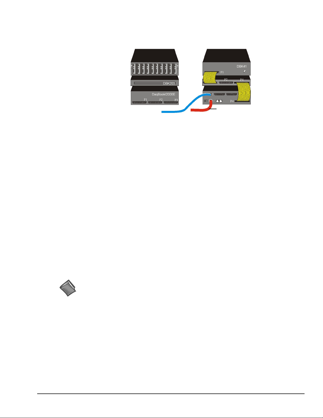
Example 2: DaqBook/2000E with a DBK41 and a DBK203
DBK41
DBK203
(Note 2)
DaqBook/2000E
To ETHERNET To POWER
DBK41
DBK203
(Note 2)
DaqBook/2000E
Channel Input Side Device Interface Side
DaqBook/2000E System
with a DBK41 and DBK203
Lines and Cables Used in Example 2 [Device Interface Side Only]:
1. Power Supply - To the DaqBook/2000E POWER IN DIN 5 connector, +10 VDC to +30 VDC,
typically from a TR40U power adapter.
2. From the DaqBook/2000E ETHERNET jack to a 10/100BaseT Ethernet Network or to the
ETHERNET jack on a PC. Applicable Ethernet patch cables (1.5-foot or 7-foot) are CA-242 and
CA-242-7, respectively.
3. From DaqBook/2000E’s P4 connector to the DBK203’s P4 connector, via a CA-195-1 cable.
4. From DBK203’s P1 connector to a DBK41’s P1 connector via one CA-37-1T cable.
Note 1: Information regarding the use of CA-37-T cables is provided on page E-9.
Note 2: In reference to the above figure, it is possible to connect the DBK41 module without using a
DBK203. In the scenario in which the DBK203 is not used, the DBK41 module would be
rotated 180° and then cabled to the DaqBook/2000E’s P1 connector via a CA-37-1 cable.
Reference Notes:
➣
For detailed information regarding the DBK41 10-Slot Analog Expansion Module or the
DBK203 Screw-Terminal Adapter Module, refer to the DBK Option Cards and Modules User’s
Manual (p/n 457-0905). A PDF version of the document is included on the data acquisition CD.
➣
Both the DBK Option Cards and Modules User’s Manual (p/n 457-0905) and the DBK Basics
section of this manual include power management information. You should use the Available
Power Chart and DBK Power Requirement Worktable to calculate your system’s power needs.
Doing so will enable you to ensure that adequate power will be supplied to all system
components. PDF versions of both documents are included on your data acquisition CD.
Installation Guide / Appendix E
927696
System Expansion IG / E-5
Page 44
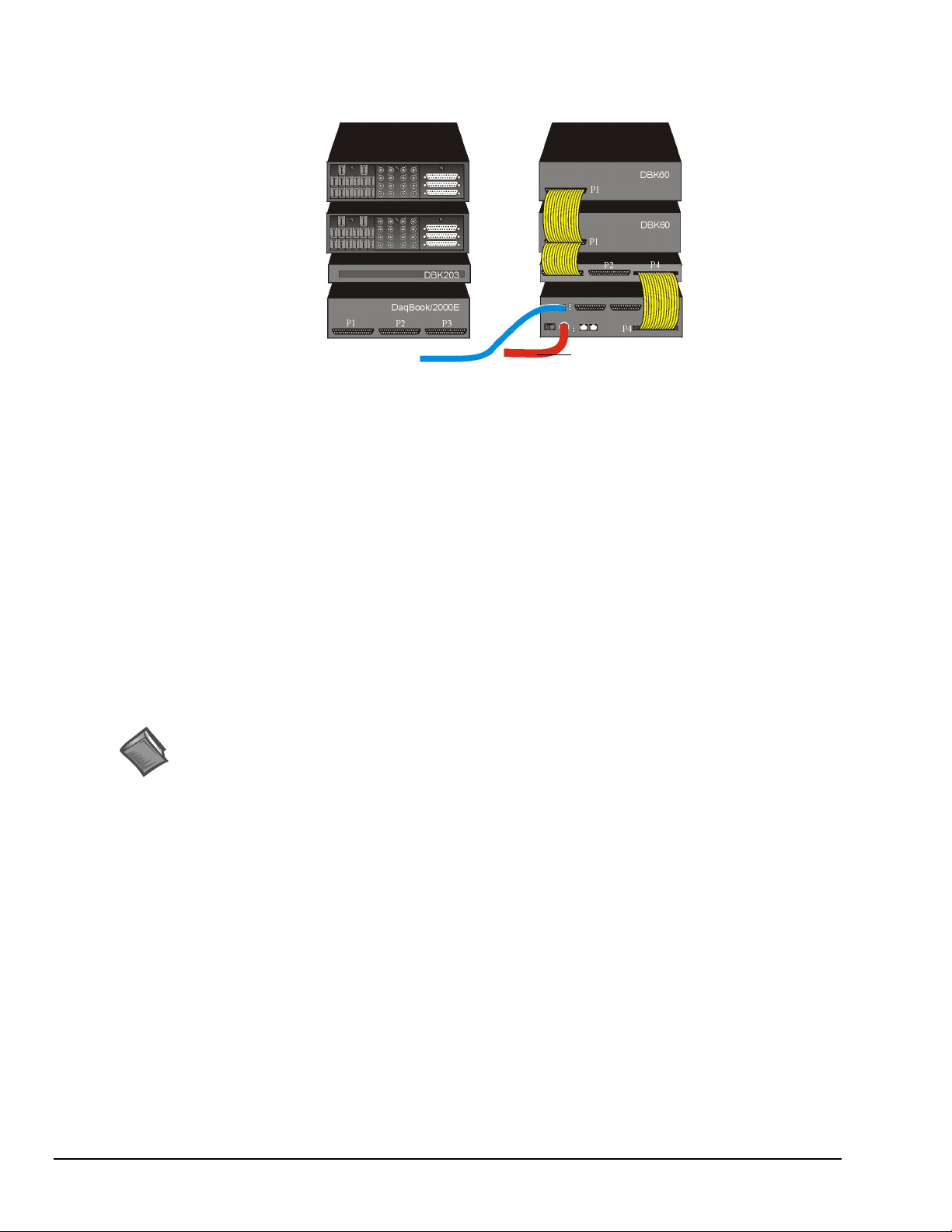
Example 3: DaqBook/2000E with two DBK60 Modules and a DBK203
DBK60 (1 of 2)
DBK60 (2 of 2)
DBK203
DaqBook/2000E
To ETHERNET To POWER
Channel Input Side Device Interface Side
DaqBook/2000E System
with two DBK60 units and a DBK203
Lines and Cables Used in Example 2 [Device Interface Side Only]:
1. Power Supply - To the DaqBook/2000E POWER IN DIN 5 connector, +10 VDC to +30 VDC,
typically from a TR40U power adapter.
2. From the DaqBook/2000E ETHERNET jack to a 10/100BaseT Ethernet Network or to the
ETHERNET jack on a PC. Applicable Ethernet patch cables (1.5-foot or 7-foot) are CA-242
and CA-242-7, respectively.
DBK60 (1 of 2)
DBK60 (2 of 2)
DBK203
DaqBook/2000E
3. From DaqBook/2000E’s P4 connector to the DBK203’s P4 connector, via a CA-195-1 cable.
4. From DBK203’s P1 connector to two DBK60 P1 connectors, via two CA-37-3T cables.
Note: Information regarding the use of CA-37-T cables is provided on page E-9.
Reference Notes:
➣
For detailed information regarding the DBK60 3-Slot Expansion Module and its related
Termination Panels, or the DBK203 Screw-Terminal Adapter Module, refer to the DBK Option
Cards and Modules User’s Manual (p/n 457-0905). A PDF version of the document is included
on the data acquisition CD.
➣
Both the DBK Option Cards and Modules User’s Manual (p/n 457-0905) and the DBK Basics
section of this manual include power management information. You should use the Available
Power Chart and DBK Power Requirement Worktable to calculate your system’s power needs.
Doing so will enable you to ensure that adequate power will be supplied to all system
components. PDF versions of both documents are included on your data acquisition CD.
IG / E-6 System Expansion
927696
Installation Guide / Appendix E
Page 45
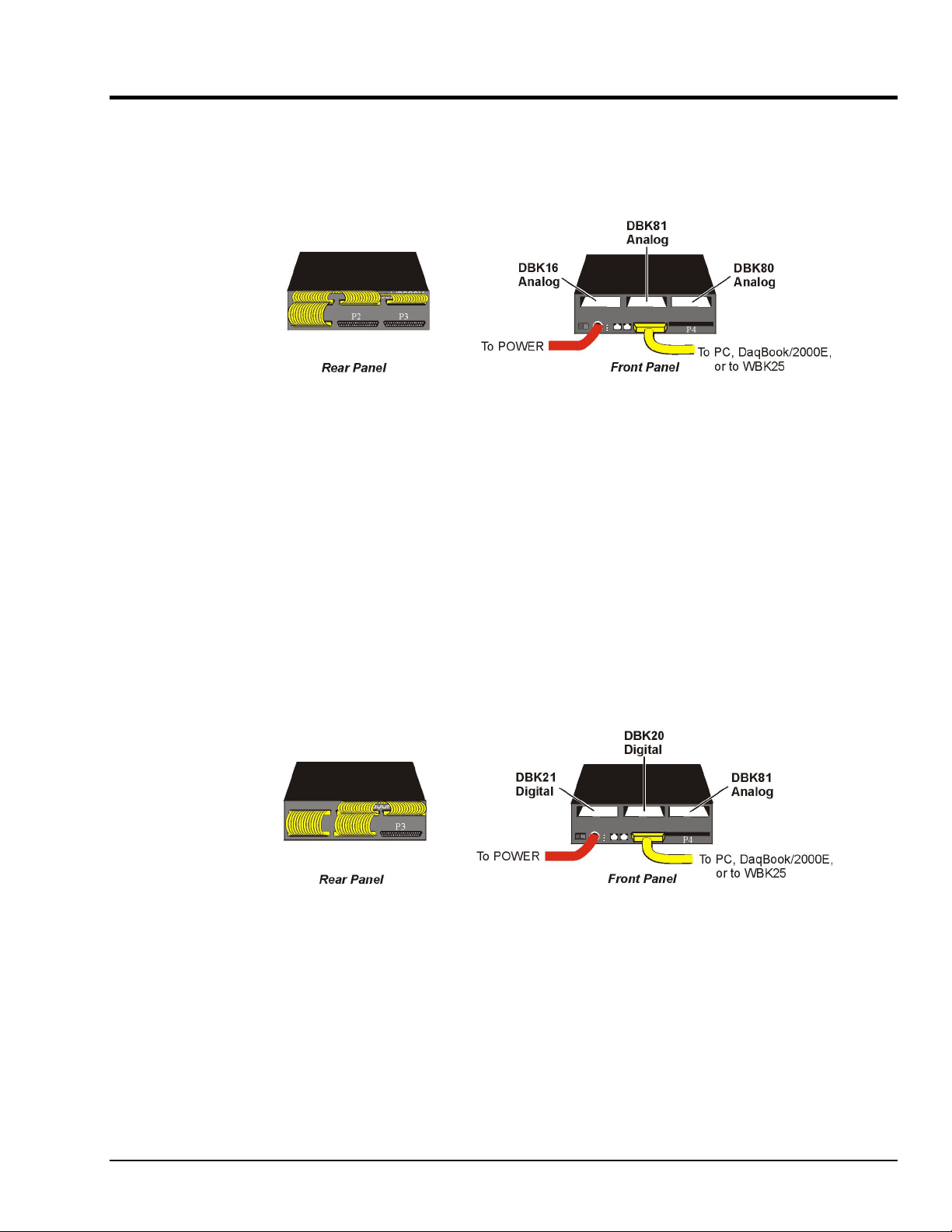
Expansion via DBK Cards in a DaqBook/2000X
This section consists of two DaqBook/2000X system examples. In the first example, 3 analog DBK cards are used.
In the second example, the system makes use of two digital DBK cards and one analog DBK card.
Example 1: DaqBook/2000X with 3 Analog DBK Cards
On DaqBook/2000X’s
front panel, P1 connects
to all 3 analog DBK cards
via a CA-37-3 Cable.
DaqBook/2000X with 3 Analog DBK Cards
Lines and Cables Used in Example 1:
On the Rear Panel:
1. Power Supply - To the DaqBook/2000X POWER IN DIN 5 connector, +10 VDC to +30 VDC,
typically from a TR40U power adapter.
2. From the DaqBook/2000X PARALLEL PORT connector to one of the following:
PC Parallel Port, DaqBook/2000E EXPANSION PORT, WBK25 EXPANSION PORT.
The connection is made via a CA-35-2 (2-foot cable) or a CA-35-12 (1-foot cable).
3. DBK16, DBK81, and DBK80 Analog DBK cards inserted in the DaqBook/2000X card slots;
then secured with jackscrews that are included with each card.
On the Front Panel:
From P1 to the DBK80 (located above P1), then to the DBK81 and the DBK16.
The connection is made via a CA-37-3 cable.
Example 2: DaqBook/2000X with 2 Digital DBK Cards and 1 Analog DBK Cards
On DaqBook/2000X’s
front panel, P1 connects
to the analog DBK 81
card via a CA-37-1 cable;
and P2 connects to the
DBK20 and DBK21 digital
cards via a CA-37-2
cable.
DaqBook/2000X with 2 Digital DBK Cards and 1 Analog DBK Card
Lines and Cables Used in Example 2:
On the Rear Panel:
1. Power Supply - To the DaqBook/2000X POWER IN DIN 5 connector, +10 VDC to +30 VDC,
typically from a TR40U power adapter.
2. From the DaqBook/2000X PARALLEL PORT connector to one of the following:
PC Parallel Port, DaqBook/2000E EXPANSION PORT, WBK25 EXPANSION PORT.
The connection is made via a CA-35-2 (2-foot cable) or a CA-35-12 (1-foot cable).
3. DBK21 digital, DBK20 digital, and DBK81 analog DBK cards inserted in the DaqBook/2000X
card slots.
(Continued)
Installation Guide / Appendix E
927696
System Expansion IG / E-7
Page 46
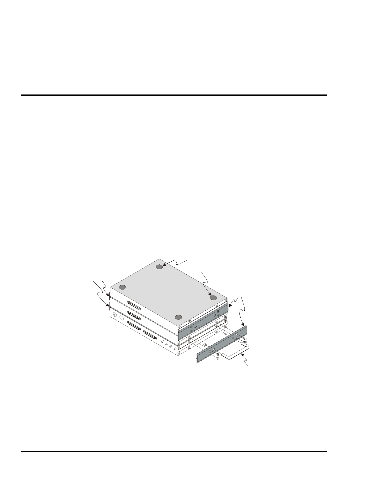
On the Front Panel:
1. From the DaqBook/2000X P1 connector to the DBK81 analog card. Connection is made
via a CA-37-1 cable.
2. From the P2 connector to the DBK20 digital card, then to the DBK21 digital card. Connection
is made via a CA-37-2 cable.
How to Mount One Module to Another
For systems that make use of several data acquisition modules, stacking units together conserves space and
simplifies cable runs. Such stacking can be facilitated with dual-lock tabs or splice plates.
• Dual-lock tabs. Dual-lock tabs, often referred to as Velcro,
stacking modules together. The tabs provide a convenient way to quickly add modules to [or remove
modules from] a system. Dual-lock tabs are often used to attach a notebook PC to a module.
• Splice Plate Kits (Fastener Panels). Optional Splice Plate Kits, also referred to as Fastener Panels,
are available through the factory. The kits include metal plates that screw into the sides of modules to
form a vertical rack of two or more modules. This method allows the “enclosure” to size itself as
needed rather than wasting space in a 1-size-fits-all type of enclosure. A handle can be attached to
the plate for convenience in portable applications.
®
provide a means of temporarily
Note that even when splice plates are used, dual-lock tabs are typically used to attach a notebook PC
to the top-level acquisition module.
Associated Part Numbers:
Splice Plate Kit: p/n 232-0810
Optional Handle: p/n HA-111
Splice Plates
Dual-lock Tabs
(To attach to
notebook PC)
Splice Plates
Optional Handle
Splice Plate Kit: p/n 232-0810
Includes 2 plates and 8 mounting
screws. The handle (HA-111) is
purchased separately.
Stacking Data Acquisition Modules
IG / E-8 System Expansion
927696
Installation Guide / Appendix E
Page 47
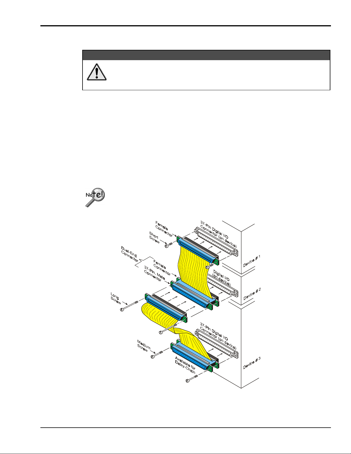
Using T-Cables
D
y
A T-Cable is a ribbon cable that extends the connections of one of the ports it plugs into, thus allowing a
second cable to plug into that port. The following figure clarifies the concept.
T-Cables are available in different lengths and can be used for linking two or more compatible devices
together via the device’s 37-pin digital I/O connectors.
The bottom-end of the T-Cable is a dual-connector, consisting of both a female connector, and a 37-pin
(male) connector. As seen in the following illustration, the T-Cable’s 37-pin (male) connector can be used
for “Daisy-Chain” applications.
Each T-Cable comes with three sets of screws. These are designated (in the diagram) as: short, medium,
and long. Use the short screws to secure the single, female-end of the cable to the device; and use the
medium length screws to secure a cable’s “dual-end” connector. Use the long screws for daisy-chain
applications (when you are connecting one T-Cable to another T-Cable).
Turn power OFF to the Daq devices and externally connected equipment while
connecting cables and setting configuration jumpers and switches or before opening
the lid. Electrical shock or damage to equipment can result even under low-voltage
conditions.
Tighten screws snug only; do not over-tighten!
CAUTION
ais
-Chain Example, Using Tw
Using two T-Cables to Connect Three Devices
Daisy-Chain Example
o T-Cables
Installation Guide / Appendix E
927696
System Expansion IG / E-9
Page 48

IG / E-10 System Expansion
927696
Installation Guide / Appendix E
Page 49
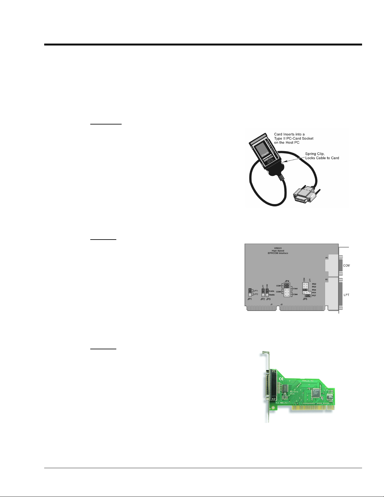
Appendix F – Adding a Parallel Port to the PC F
If you need to connect a DaqBook/2000A or DaqBook/2000X to a notebook or desktop PC that has no parallel port
available, you can most likely use an interface device to obtain a port. To do so, your PC needs to have an available
PC-Card Slot, ISA Bus Slot, PCI Bus Slot, or an Ethernet jack. You can use one of the following devices,
depending on which type of interface applies.
WBK20A
For Interfacing with a PC-Card Slot
If you need to connect your DaqBook/2000A or
DaqBook/2000X to a notebook PC that has no
available parallel port, you can use a WBK20A.
This device consists of a PCMCIA Interface Card,
cable, and DB25 Connector.
Refer to separate instructions [supplied with the
WBK20A] if applicable.
WBK20A, Plugs into a PC-Card Slot
WBK21
For Interfacing with an ISA Bus Slot.
If you need to connect your DaqBook/2000A or
DaqBook/2000X to a desktop PC that has no
available parallel port, you may be able to use the
WBK21 option to provide a port. The board’s
connector is labeled LPT. WBK21 plugs into and
ISA Bus Slot.
Refer to separate instructions [supplied with the
WBK21] if applicable.
WBK23
For Interfacing with a PCI Bus Slot.
If you need to connect your DaqBook/2000A or
DaqBook/2000X to a desktop PC that has no
available parallel port, you may be able to use a
WBK23 to provide a port. The WBK23 plugs into
a PCI Bus Slot.
Refer to separate instructions [supplied with the
WBK23] if applicable.
Installation Guide / Appendix F
WBK21, Plugs into an ISA Bus Slot
WBK23, Plugs into a PCI Bus Slot
927696
Adding a Parallel Port to the PC IG / F-1
Page 50
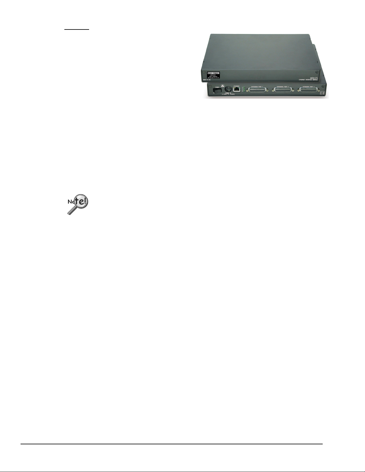
WBK25
For interfacing with an Ethernet jack on a
PC or on a network hub.
If you are using a PC or a network with an
available Ethernet jack you can obtain three
parallel ports by using a WBK25 Ethernet-toParallel Port Interface.
The WBK25 provides high-speed Ethernet
connectivity for WaveBook, DaqBook, WBK40,
and WBK41 systems. Connection to the Ethernet
is made via an Ethernet patch cable, which links the
WBK25’s 10/100BaseT Ethernet port to a PC’s
Ethernet jack or an Ethernet network hub.
The WBK25 includes three parallel ports, labeled as expansion ports 1 through 3. Each of these parallel
ports can be attached to one of the designated acquisition devices via a parallel cable. The ports cannot be
used for auxiliary devices such as printers and scanners.
Refer to separate instructions [supplied with the WBK25] if applicable.
WBK25’s three parallel ports are labeled as expansion ports 1 through 3. They are
used to connect to WaveBook, DaqBook, WBK40, and WBK41 systems via parallel
cables. The ports cannot be used for other parallel devices, such as printers and
scanners.
The WBK25 Ethernet-to-Parallel Port Interface
connects to the Ethernet and provides three
parallel ports.
IG / F-2 Adding a Parallel Port to the PC
927696
Installation Guide / Appendix F
Page 51
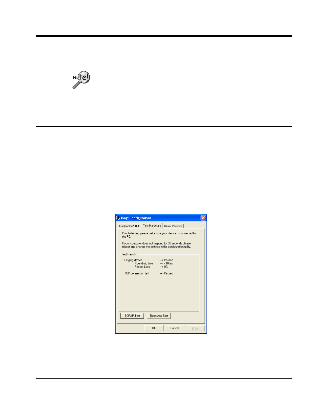
Appendix G – TCP/IP and Resource Tests G
Before you run a test
Before testing the system, make sure the device has been properly installed and powered-on. Make sure all
cables are properly and securely connected.
When testing a WaveBook or DaqBook device, if the unit does not respond within 30
seconds perform the following steps:
1) reboot the system
2) upon power-up, re-open the Daq* Configuration applet
3) select another configuration setting
4) reinitiate the test
How to run the TCP/IP Test
The TCP/IP (Transmission Control Protocol/Internet Protocol) test is for Ethernet devices only. The test is
accessed and initiated as follows.
a. Open the Control Panel by navigating from the Windows’ Desktop as follows:
Start Menu ⇒ Settings ⇒ Control Panel
b. From the Control Panel, double-click the Daq* Configuration icon.
c. Select the device that you want to test from the Device Inventory configuration tree.
d. Click the <Properties> button. The Properties dialog box will open.
e. Click the “Test Hardware” tab.
f. Click the <TCP/IP Test> button.
(The TCP/IP test is for Ethernet devices only)
Installation Guide / Appendix G
Results of a TCP/IP Test for a
DaqBook/2000E
927696
TCP/IP and Resource Tests IG / G-1
Page 52
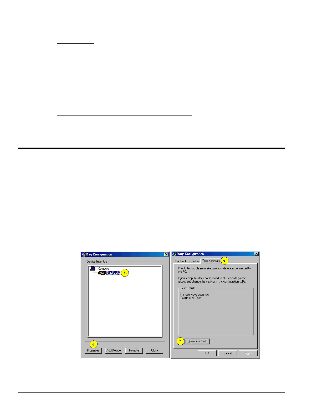
What does the TCP/IP test tell me?
The TCP/IP test provides test results for “Pinging Device” and “TCP Connection Test.”
Pinging Device
. The Pinging Device test is an ICMP (Internet Control Message Protocol) ping test. In
addition to indicating either “Passed” or “Failed,” the test displays;
(a) The round-trip time of the ping, for example, <10 ms.
(b) Packet Loss expressed as a percent of data lost.
A long ping round trip time, for example, >50 ms and/or any packet loss indicates a slow network that is
not optimized.
If the Pinging Device Test fails a <Details> button will appear just above the <Resource Test> button. If
this is the case, click the <Details> button to obtain possible causes and possible solutions.
TCP (Transmission Control Protocol) Connection Test
passed or failed. If the TCP test failed a <Details> button will appear just above the <Resource Test>
button. If this is the case, click the <Details> button to obtain possible causes and possible solutions.
How to run the Resource Tests
For Ethernet devices, such as a WaveBook/516E or DaqBook/2000E you can run the Resource Test after a
successful completion of the TCP/IP test with a simple click of the <Resource Test> button. For nonEthernet devices complete the following steps.
a. Open the Control Panel by navigating from the Windows’ Desktop as follows:
Start Menu ⇒ Settings ⇒ Control Panel
. The result of the TCP test will be either
b. From the Control Panel, double-click the Daq* Configuration icon.
c. Select the device that you want to test from the Device Inventory configuration tree
(see following figure, item “c”).
d. Click the <Properties> button. The Properties dialog box will open.
e. Click the “Test Hardware” tab.
f. Click the <Resource Test> button.
IG-2 TCP/IP and Resource Tests
Preparing to Run a Resource Test
927696
Installation Guide / Appendix G
Page 53
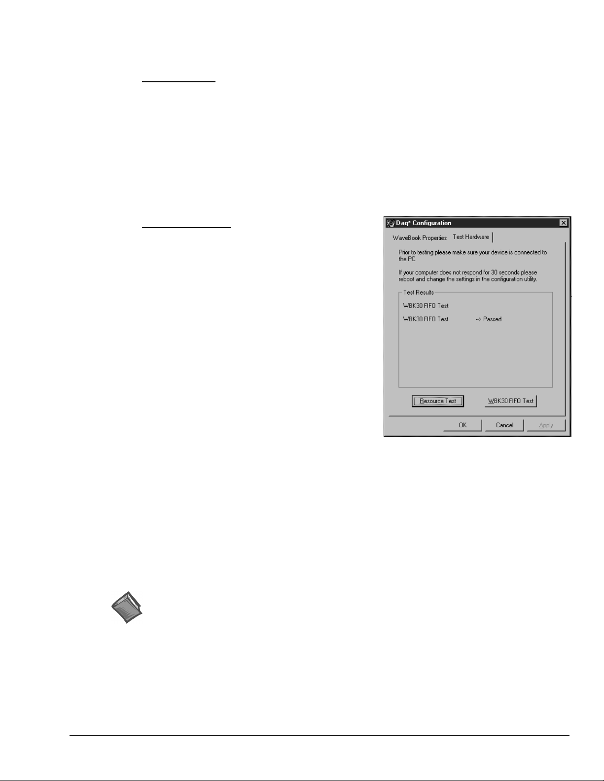
What does the Resource Test tell me?
The Resource Test includes two categories of test, Resource Tests and Performance Tests.
Resource Tests
. The resource tests are intended to test system capability for the current device
configuration. Resource tests are pass/fail. Test failure may indicate a lack of availability of the resource,
or a possible resource conflict.
Base Address Test. This resource test checks the base address for the selected port. Failure of this test may
indicate that the port is not properly configured within the system. See relevant operating system and
computer manufacturer’s documentation to correct the problem.
Interrupt Level Test – Tests the ability of a parallel port to generate interrupts. Failure of this test may
indicate that the parallel port may be currently unable to generate the necessary hardware interrupt, while
other parallel port devices may work OK in this mode. Some parallel port devices (such as printers) do not
require interrupts to work properly. See relevant operating system and computer manufacturer’s
documentation to correct the problem.
Performance Tests
to check various device functions, using the current
device configuration. Performance tests provide
quantitative results for each supported functional group.
Test results represent maximum rates the various
operations can be performed. The rates depend on the
selected parallel port protocol, and vary according to port
hardware capabilities.
The ADC FIFO Input Speed part of the test results in a
display of the maximum rate at which data can be
transferred from the tested device’s internal ADC FIFO to
computer memory through the parallel port. Results are
given in samples/second, where a sample (2 bytes in
length) represents a single A/D value.
. These types of tests are intended
If the device has a WBK30 card installed, a WBK30
FIFO Test can be run.
WBK30 FIFO Test. This performance test checks the
data-storing capabilities of the optional, WBK30 memory
card.
Note that the figure to the right represents results from a
previous test. Initially the screen shows no test results.
When the test is completed successfully, the Daq*
Configuration Test Dialog Box indicates a passed
condition. For example, in the above figure:
WBK30 FIFO Test Æ Passed.
“Passed” messages indicate that you can exit the test
program and run your application.
Reference Notes:
➣
If you experience difficulties, please consult additional user documentation, as applicable, before
calling technical support. User documentation is included on your data acquisition CD, and is
installed automatically as a part of product support, when your software is installed. The default
location is the Programs Group. The documentation includes API information and a great deal of
material regarding specific DBK cards and modules.
Daq* Configuration - Test Hardware Dialog Box
➣
Documents can be read directly from the data acquisition CD via the <View PDFs> button located
on the CD’s opening screen.
Installation Guide / Appendix G
927696
TCP/IP and Resource Tests IG / G-3
Page 54

IG-4 TCP/IP and Resource Tests
927696
Installation Guide / Appendix G
Page 55
System Connections and Pinouts
Overview …… sc-1
P1 – Analog I/O …… sc-3
P2 – Digital I/O …… sc-4
P3 – Pulse/Frequency/Digital I/O …… sc-5
P4 to P1, P2, and P3 Correlation …… sc-6
DBK200 Series, Selected P4 Connector Options …… sc-9
Turn off power to all devices connected to the system before connecting cables or
equipment can result even under low-voltage conditions.
setting configuration jumpers and switches. Electrical shock or damage to
The discharge of static electricity can damage some electronic components.
Semiconductor devices are especially susceptible to ESD damage. You should
always handle components carefully, and you should never touch connector pins or
circuit components unless you are following ESD guidelines in an appropriate ESD
controlled area. Such guidelines include the use of properly grounded mats and
wrist straps, ESD bags and cartons, and related procedures.
CAUTION
CAUTION
Overview
DaqBook/2000 Series Devices have 37-pin P1, P2 and P3 connectors. P1 is used for Analog I/O,
P2 for Digital I/O, and P3 for Pulse/Frequency/Digital I/O. Each DaqBook/2000 Series device includes a
100-pin P4 connector. In regard to P4, a DBK200 Series Card or Module can be connected to it via cable
to provide different connection options for Analog, Digital, and Pulse/Frequency/Digital I/O connectivity.
The most preferred of the DBK200 Series expansion options are discussed following the Pinout Sections
for P1, P2, P3, and P4.
The P4 connector on a DaqBook/2000 Series device shares signal connections with the P1,
P2, and P3 connectors. P4 offers no additional I/O. Connecting a DBK200 Series Option
to P4 via a CA-195 cable distances the P1, P2, P3 connection from the DaqBook/2000
Series device. It does not provide any new signal I/O. See the following Caution.
CAUTION
Signal conflicts between a DaqBook/2000 Series device’s P1, P2, P3 connectors and its
P4 connector can result in erroneous readings and possible equipment damage.
Therefore, when connections have been made to P1, P2, and/or P3, use caution when
making connections through P4, and visa versa.
The following pinouts indicate the P1, P2, and P3 pins, and their P4 equivalents. Use the
pinouts to avoid making duplicate signal connections.
DaqBook/2000 Series User’s Manual
927196
System Connections & Pinouts sc-1
Page 56
There are two ways to connect a DBK option to a DaqBook/2000 Series device. The first
method is preferable, as it introduces less noise.
Preferred Method – (a) Connect a CA-37-x cable to the appropriate DB37 connector
[P1, P2, or P3] on the DaqBook/2000 Series device. (b) Connect the
free end of the cable to the DBK card or module.
Optional Method – (a) Connect a CA-195-x cable to the P4 connector on the
DaqBook/2000 Series device. (b) Connect the free end of the cable
to a DBK200 Series device. (c) Connect the DBK option to the
DBK200 Series device, as applicable.
The primary reason that less noise is seen in the “preferred” method is that a
DaqBook/2000 Series device’s P1 connector pertains only to analog acquisition signals
and the P2 connector pertains only to digital I/O. This provides a strong degree of
isolation between the two signal types. However, in the case of a CA-195-x cable
connected to P4, digital and analog signals co-exist in one cable.
If you need to use the P4 connection method, use of the 8-inch ribbon cable (CA-195-1)
will result in the lowest level of crosstalk [for that method].
.
CAUTION
Do not confuse connectors. Ensure that you only connect P1 I/Os to P1,
P2 I/Os to P2, and P3 I/Os to P3. Improper connection may result in equipment damage.
CAUTION
Signal conflicts between a DaqBook/2000 Series device’s P1, P2, P3 connectors and its
P4 connector can result in erroneous readings and possible equipment damage.
Therefore, when connections have been made to P1, P2, and/or P3, use caution when
making connections through P4, and visa versa.
The following pinouts indicate the P1, P2, and P3 pins, and their P4 equivalents. Use the
pinouts to avoid making duplicate signal connections.
sc-2 System Connections & Pinouts
927196
DaqBook/2000 Series User’s Manual
Page 57
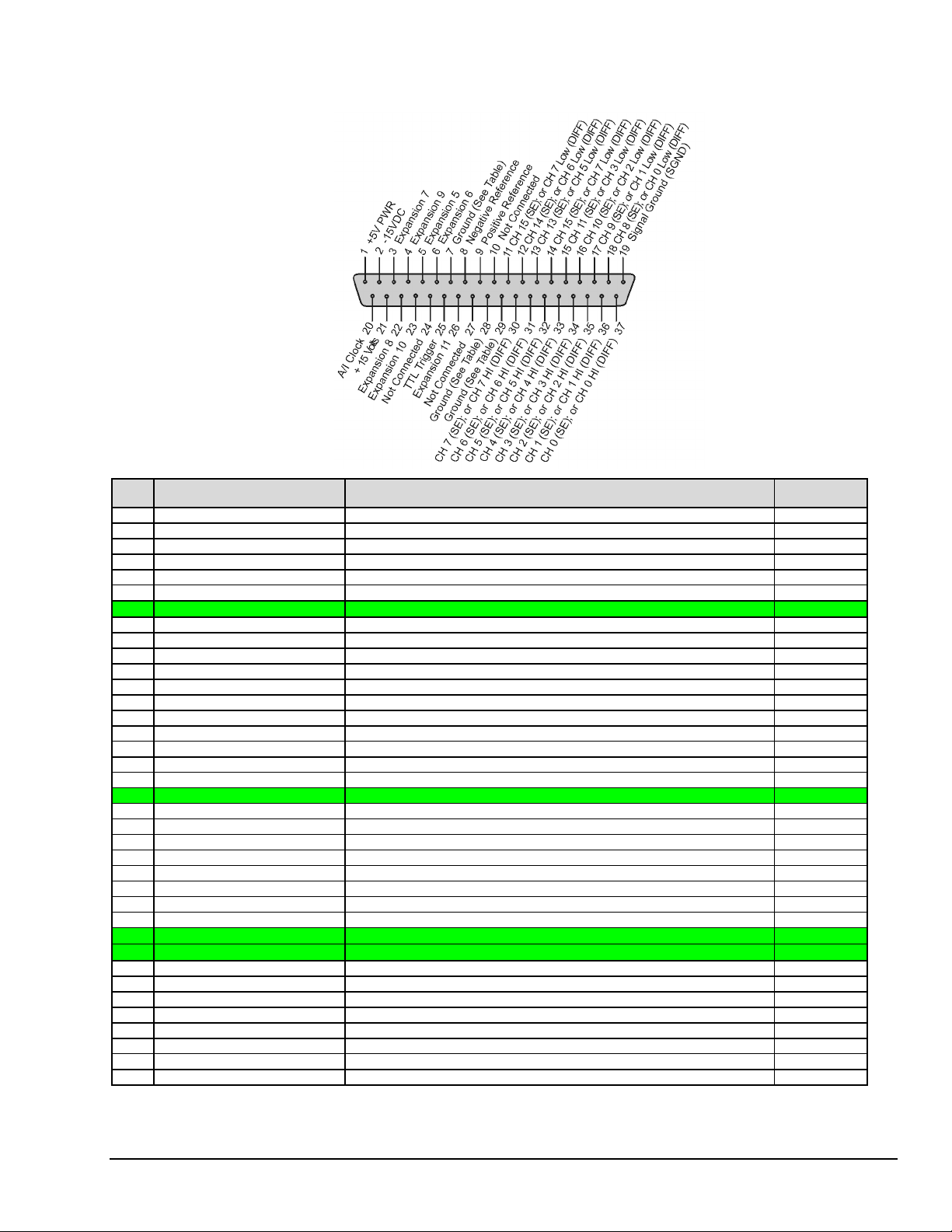
P1 for DaqBook/2000 Series Devices Analog I/O
P1
Pin
1 +5 Volts Expansion +5 V power A1
2 -15 Volts Expansion -15 VDC power A48
3 Expansion 7 Digital OUT, external ADDRESS select bit 3 B32
4 Expansion 9 Digital OUT, external ADDRESS select bit 1 B33
5 Expansion 5 Digital OUT, external GAIN select bit 1 B31
6 Expansion 6 Digital OUT, external GAIN select bit 0 A32
7 DGND Digital Ground A10, B14, A23, A24, B25, B27
8 Negative Reference Analog, -5 V reference A36
9 Positive Reference Analog +5V reference B35
10 Not Connected N/A N/A
11 CH 15 (SE), or CH 7 LO DIFF Ch 15 HI IN (single-ended mode) / Ch 7 LO IN (differential mode) B36
12 CH 14 (SE), or CH 6 LO DIFF Ch 14 HI IN (single-ended mode) / Ch 6 LO IN (differential mode) A38
13 CH 13 (SE), or CH 5 LO DIFF Ch 13 HI IN (single-ended mode) / Ch 5 LO IN (differential mode) B39
14 CH 12 (SE), or CH 4 LO DIFF Ch 12 HI IN (single-ended mode) / Ch 4 LO IN (differential mode) A41
15 CH 11 (SE), or CH 3 LO DIFF Ch 11 HI IN (single-ended mode) / Ch 3 LO IN (differential mode) B42
16 CH 10 (SE), or CH 2 LO DIFF Ch 10 HI IN (single-ended mode) / Ch 2 LO IN (differential mode) A44
17 CH 9 (SE), or CH 1 LO DIFF Ch 9 HI IN (single-ended mode) / Ch 1 LO IN (differential mode) B45
18 CH 8 (SE), or CH 0 LO DIFF Ch 8 HI IN (single-ended mode) / Ch 0 LO IN (differential mode) A47
19 Signal Ground (SGND) Sense Common (SGND) A45
20 A/I Clock External ADC Pacer Clock Input / Internal ADC Pacer Clock Output B26
21 +15 Volts Expansion +15 V power B48
22 Expansion 8 Digital OUT, external ADDRESS select bit 2 A33
23 Expansion 10 Digital OUT, external ADDRESS select bit 0 A34
24 Not Connected N/A N/A
25 TTL Trigger Digital IN, External TTL Trigger Input A27
26 Expansion 11 Digital OUT, Simultaneous sample and hold (SSH) B34
27 Not Connected N/A N/A
28 AGND Analog Ground A31, A35, B37, A39, B40, A42, B43, B46
29 AGND Analog Ground
30 CH 7 (SE), or CH 7 HI DIFF Ch 7 IN (single-ended mode) / Ch 7 HI IN (differential mode) A37
31 CH 6 (SE), or CH 6 HI DIFF Ch 6 IN (single-ended mode) / Ch 6 HI IN (differential mode) B38
32 CH 5 (SE), or CH 5 HI DIFF Ch 5 IN (single-ended mode) / Ch 5 HI IN (differential mode) A40
33 CH 4 (SE), or CH 4 HI DIFF Ch 4 IN (single-ended mode) / Ch 4 HI IN (differential mode) A33, B41
34 CH 3 (SE), or CH 3 HI DIFF Ch 3 IN (single-ended mode) / Ch 3 HI IN (differential mode) A43
35 CH 2 (SE), or CH 2 HI DIFF Ch 2 IN (single-ended mode) / Ch 2 HI IN (differential mode) B44
36 CH 1 (SE), or CH 1 HI DIFF Ch 1 IN (single-ended mode) / Ch 1 HI IN (differential mode) A46
37 CH 0 (SE), or CH 0 HI DIFF Ch 0 IN (single-ended mode) / Ch 0 HI IN (differential mode) B47
Signal Name
Description for P1 Pin Use
A31, A35, B37, A39, B40, A42, B43, B46
P4
Correlation
⇐
⇐
⇐
DaqBook/2000 Series User’s Manual
927196
System Connections & Pinouts sc-3
Page 58
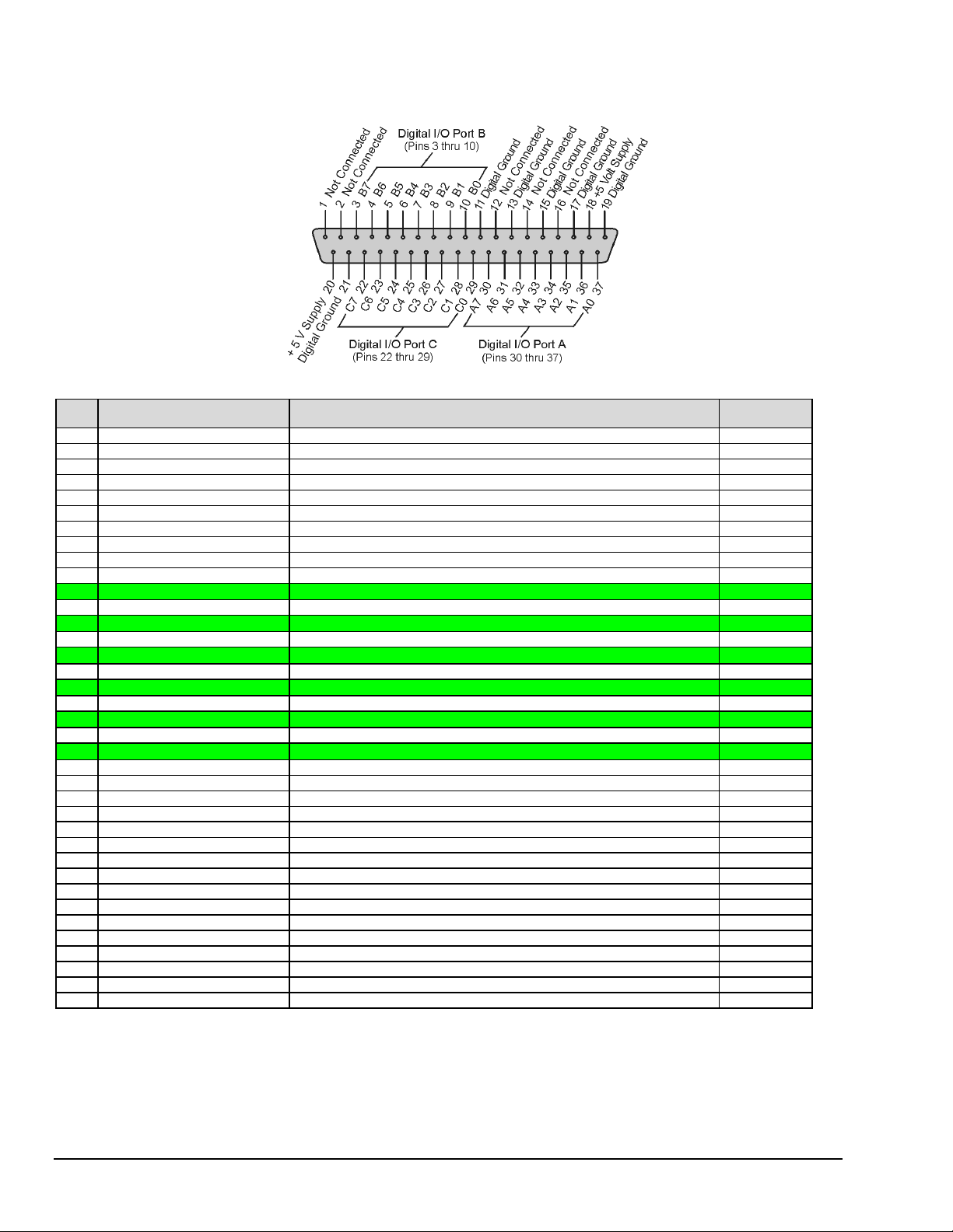
P2 for DaqBook/2000 Series Devices Digital I/O
P2
Pin
1 Not Connected N/A N/A
2 Not Connected N/A N/A
3 Port B - B7 Digital I/O: P2 Digital Port B, Bit 7; or, P2 Expansion Address Bit 0 Out B10
4 Port B - B6 Digital I/O: P2 Digital Port B, Bit 6; or, P2 Expansion Address Bit 1 Out A11
5 Port B - B5 Digital I/O: P2 Digital Port B, Bit 5; or, P2 Expansion Address Bit 2 Out B11
6 Port B - B4 Digital I/O: P2 Digital Port B, Bit 4; or, P2 Expansion Address Bit 3 Out A12
7 Port B - B3 Digital I/O: P2 Digital Port B, Bit 3; or, P2 Expansion Address Bit 4 Out B12
8 Port B - B2 Digital I/O: P2 Digital Port B, Bit 2; or, P2 Expansion RESET Output A13
9 Port B - B1 Digital I/O: P2 Digital Port B, Bit 1; or, P2 Expansion WRITE Output B13
10 Port B - B0 Digital I/O: P2 Digital Port B, Bit 0; or, P2 Expansion READ Output A14
11 DGND Digital Ground A10, B14, A23, A24, B25, B27
12 Not Connected N/A N/A
13 DGND Digital Ground A10, B14, A23, A24, B25, B27
14 Not Connected N/A N/A
15 DGND Digital Ground A10, B14, A23, A24, B25, B27
16 Not Connected N/A N/A
17 DGND Digital Ground A10, B14, A23, A24, B25, B27
18 + 5 Volt Supply Expansion +5 Volt Power A1, B1
19 DGND Digital Ground A10, B14, A23, A24, B25, B27
20 + 5 Volt Supply Expansion +5 Volt Power A1, B1
21 DGND Digital Ground A10, B14, A23, A24, B25, B27
22 Port C - C7 Digital I/O: P2 Digital Port C, Bit 7; or, P2 Expansion Data Bit 7 A6
23 Port C - C6 Digital I/O: P2 Digital Port C, Bit 6; or, P2 Expansion Data Bit 6 B6
24 Port C - C5 Digital I/O: P2 Digital Port C, Bit 5; or, P2 Expansion Data Bit 5 A7
25 Port C - C4 Digital I/O: P2 Digital Port C, Bit 4; or, P2 Expansion Data Bit 4 B7
26 Port C - C3 Digital I/O: P2 Digital Port C, Bit 3; or, P2 Expansion Data Bit 3 A8
27 Port C - C2 Digital I/O: P2 Digital Port C, Bit 2; or, P2 Expansion Data Bit 2 B8
28 Port C - C1 Digital I/O: P2 Digital Port C, Bit 1; or, P2 Expansion Data Bit 1 A9
29 Port C - C0 Digital I/O: P2 Digital Port C, Bit 0; or, P2 Expansion Data Bit 0 B9
30 Port A - A7 Digital I/O: P2 Digital Port A, Bit 7 A2
31 Port A - A6 Digital I/O: P2 Digital Port A, Bit 6 B2
32 Port A - A5 Digital I/O: P2 Digital Port A, Bit 5 A3
33 Port A - A4 Digital I/O: P2 Digital Port A, Bit 4 B3
34 Port A - A3 Digital I/O: P2 Digital Port A, Bit 3 A4
35 Port A - A2 Digital I/O: P2 Digital Port A, Bit 2 B4
36 Port A - A1 Digital I/O: P2 Digital Port A, Bit 1 A5
37 Port A - A0 Digital I/O: P2 Digital Port A, Bit 0 B5
Signal Name
Description for P2 Pin Use
P4
Correlation
⇐
⇐
⇐
⇐
⇐
⇐
sc-4 System Connections & Pinouts
927196
DaqBook/2000 Series User’s Manual
Page 59
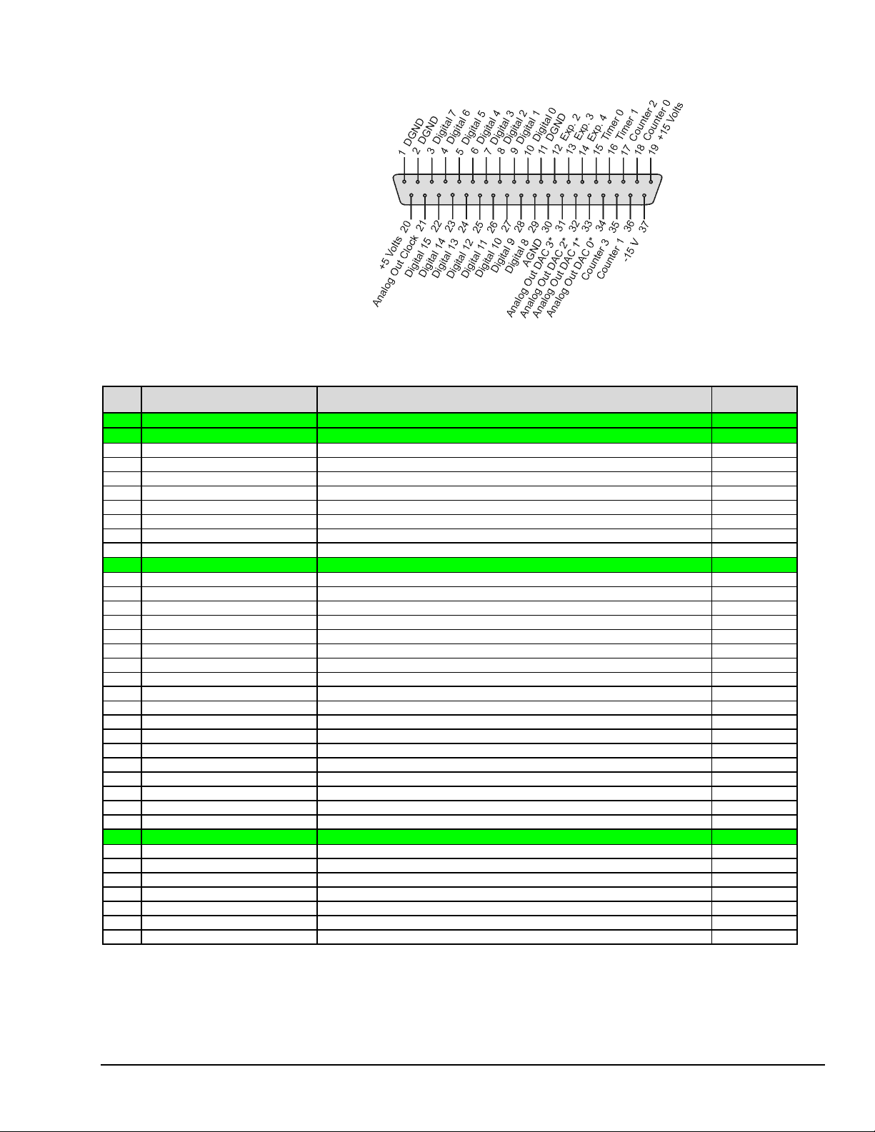
P3 for DaqBook/2000 Series Devices Pulse/Frequency/Digital I/O
P3
DB37 P3 Connector
Pin
1 DGND Digital Ground A10, B14, A23, A24, B25, B27
2 DGND Digital Ground A10, B14, A23, A24, B25, B27
3 Digital 7 P3 Digital Port Bit 7 B19
4 Digital 6 P3 Digital Port Bit 6 A19
5 Digital 5 P3 Digital Port Bit 5 B20
6 Digital 4 P3 Digital Port Bit 4 A20
7 Digital 3 P3 Digital Port Bit 3 B21
8 Digital 2 P3 Digital Port Bit 2 A21
9 Digital 1 P3 Digital Port Bit 1 B22
10 Digital 0 P3 Digital Port Bit 0 A22
11 DGND Digital Ground A10, B14, A23, A24, B25, B27
12 Expansion 2 Reserved for XC/D- --13 Expansion 3 Reserved for XWR- --14 Expansion 4 Reserved for XRD- ---
15 Timer 0 P3 Timer 0 Output B24
16 Timer 1 P3 Timer 1 Output A25
17 Counter 2 P3 Counter 2 Input B28
18 Counter 0 P3 Counter 0 Input B29
19 + 15 Volts Expansion, +15 VDC B48
20 + 5 Volt Supply Expansion, +5 Volt Power A1, B1
21 Analog Out Clock External DAC Pacer Clock Input/Internal DAC Pacer Clock Output A26
22 Digital 15 Digital I/O; P3 Digital Port Bit 15 B15
23 Digital 14 Digital I/O; P3 Digital Port Bit 14 A15
24 Digital 13 P3 Digital Port Bit 13 B16
25 Digital 12 P3 Digital Port Bit 12 A16
26 Digital 11 P3 Digital Port Bit 11 B17
27 Digital 10 P3 Digital Port Bit 10 A17
28 Digital 9 P3 Digital Port Bit 9 B18
29 Digital 8 P3 Digital Port Bit 8 A18
30 AGND Analog Ground A31, A35, B37, A39, B40, A42, B43, B46
31 Analog Out DAC 3 (Note) Analog DAC 3 Output (Note) B50
32 Analog Out DAC 2 (Note) Analog DAC 2 Output (Note) B49
33 Analog Out DAC 1 (Note) Analog DAC 1 Output (Note) A50
34 Analog Out DAC 0 (Note) Analog DAC 0 Output (Note) A49
35 Counter 3 P3 Counter 3 Input A28
36 Counter 1 P3 Counter 1 Input A29
37 - 15 Volts Expansion, - 15 VDC Power A48
: Pins 31, 32, 33, and 34 on the P3 DB37 connector are used for Analog Out DACs. These four pins only apply to a
*
Note
Signal Name
DaqBook/2000 Series device when a DBK46 Analog Channel Output option card is installed in that device. Installation
of the DBK46 option is only to be performed at the factory.
Description for P3 Pin Use
P4
Correlation
⇐
⇐
⇐
⇐
DaqBook/2000 Series User’s Manual
927196
System Connections & Pinouts sc-5
Page 60
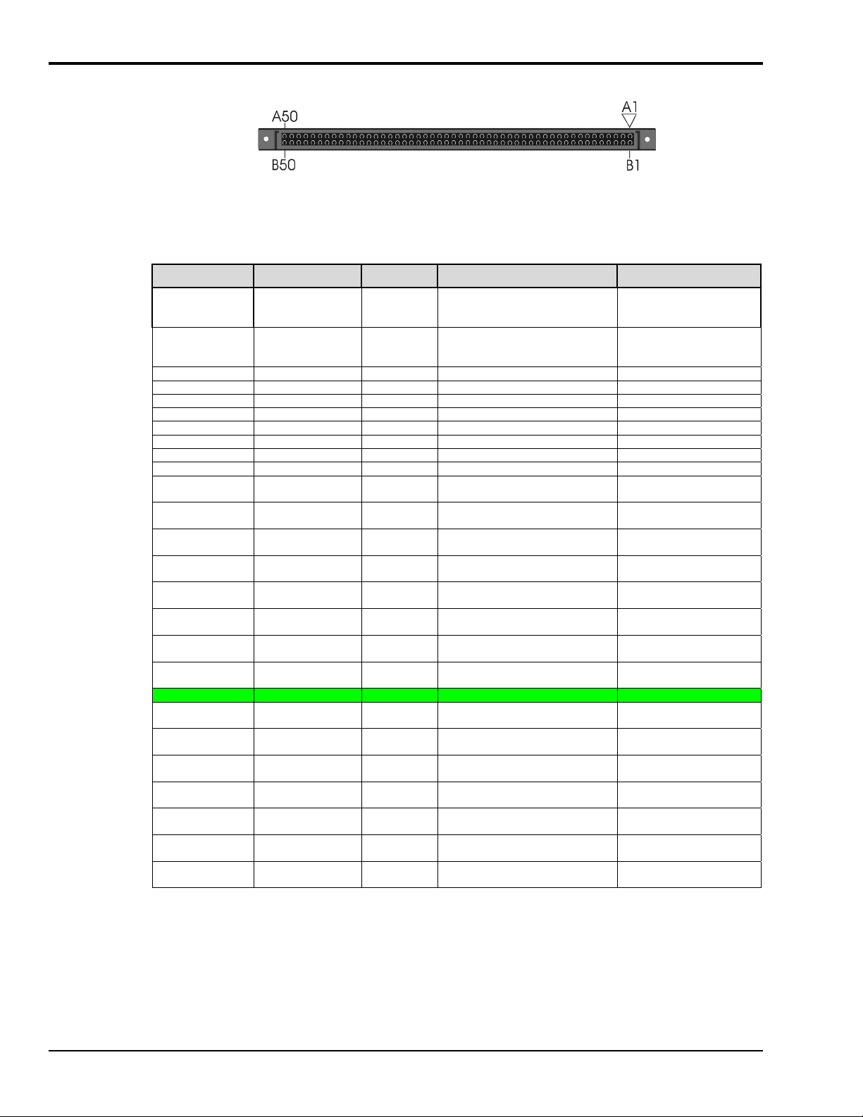
P4 to P1, P2 and P3 Correlation for DaqBook/2000 Series Devices
P4, 100-Pin Connector
The following table lists the correlation between the P4 I/O lines and their respective P1, P2 and P3 pin
locations on the DaqBook/2000 Series devices.
P4 Pin Signal Type Description P1, P2, P3 Correlation
A1 +5VDC Power Expansion +5 Volts P1 pin 1
B1 +5VDC Power Expansion +5 Volts P1 pin 1
A2 Port A bit 7 Dig I/O P2 Digital Port A, bit 7 P2 pin 30
B2 Port A bit 6 Dig I/O P2 Digital Port A, bit 6 P2 pin 31
A3 Port A bit 5 Dig I/O P2 Digital Port A, bit 5 P2 pin 32
B3 Port A bit 4 Dig I/O P2 Digital Port A, bit 4 P2 pin 33
A4 Port A bit 3 Dig I/O P2 Digital Port A, bit 3 P2 pin 34
B4 Port A bit 2 Dig I/O P2 Digital Port A, bit 2 P2 pin 35
A5 Port A bit 1 Dig I/O P2 Digital Port A, bit 1 P2 pin 36
B5 Port A bit 0 Dig I/O P2 Digital Port A, bit 0 P2 pin 37
A6 Port C bit 7 Dig I/O P2 Digital Port C, bit 7 -or-
P2 expansion Data bit 7
B6 Port C bit 6 Dig I/O P2 Digital Port C, bit 6 -or-
P2 expansion Data bit 6
A7 Port C bit 5 Dig I/O P2 Digital Port C, bit 5 -or-
P2 expansion Data bit 5
B7 Port C bit 4 Dig I/O P2 Digital Port C, bit 4 -or-
P2 expansion Data bit 4
A8 Port C bit 3 Dig I/O P2 Digital Port C, bit 3 -or-
P2 expansion Data bit 3
B8 Port C bit 2 Dig I/O P2 Digital Port C, bit 2 -or-
P2 expansion Data bit 2
A9 Port C bit 1 Dig I/O P2 Digital Port C, bit 1 -or-
P2 expansion Data bit 1
B9 Port C bit 0 Dig I/O P2 Digital Port C, bit 0 -or-
P2 expansion Data bit 0
A10 Ground Dig I/O Digital Common Multiple, see P1, P2, P3
B10 Port B bit 7 Dig I/O P2 Digital Port B, bit 7 -or-
P2 expansion address bit 0
A11 Port B bit 6 Dig I/O P2 Digital Port B, bit 6 -or-
P2 expansion address bit 1
B11 Port B bit 5 Dig I/O P2 Digital Port B, bit 5 -or-
P2 expansion address bit 2
A12 Port B bit 4 Dig I/O P2 Digital Port B, bit 4 -or-
P2 expansion address bit 2
B12 Port B bit 3 Dig I/O P2 Digital Port B, bit 3 -or-
P2 expansion address bit 3
A13 Port B bit 2 Dig I/O P2 Digital Port B, bit 2 -or-
P2 expansion RESET
B13 Port B bit 1 Dig I/O P2 Digital Port B, bit 1 -or-
P2 expansion WRITE
This table is continued.
P2 pin 18, 20
P3 pin 20
P2 pin 18, 20
P3 pin 20
P2 pin 22
P2 pin 23
P2 pin 24
P2 pin 25
P2 pin 26
P2 pin 27
P2 pin 28
P2 pin 29
P2 pin 3
P2 pin 4
P2 pin 5
P2 pin 6
P2 pin 7
P2 pin 8
P2 pin 9
sc-6 System Connections & Pinouts
927196
DaqBook/2000 Series User’s Manual
Page 61
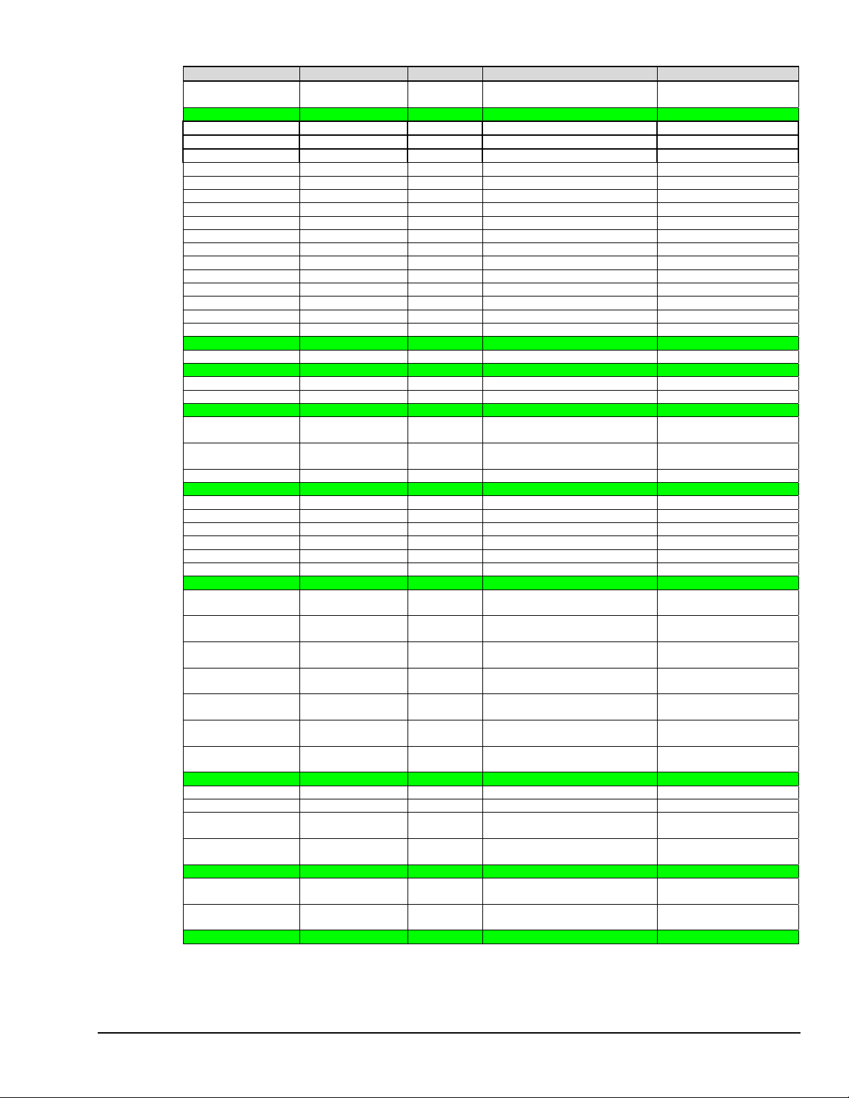
P4 Pin Signal Type Description P1, P2, P3 Correlation
A14 Port B bit 0 Dig I/O P2 Digital Port B, bit 0 -or-
P2 expansion READ
B14 Ground Dig I/O Digital Common Multiple, see P1, P2, P3
A15 P3 Dig bit 14 Dig I/O P3 Digital Port bit 14 P3 pin 23
B15 P3 Dig bit 15 Dig I/O P3 Digital Port bit 15 P3 pin 22
A16 P3 Dig bit 12 Dig I/O P3 Digital Port bit 12 P3 pin 25
B16 P3 Dig bit 13 Dig I/O P3 Digital Port bit 13 P3 pin 24
A17 P3 Dig bit 10 Dig I/O P3 Digital Port bit 10 P3 pin 27
B17 P3 Dig bit 11 Dig I/O P3 Digital Port bit 11 P3 pin 26
A18 P3 Dig bit 8 Dig I/O P3 Digital Port bit 8 P3 pin 29
B18 P3 Dig bit 9 Dig I/O P3 Digital Port bit 9 P3 pin 28
A19 P3 Dig bit 6 Dig I/O P3 Digital Port bit 6 P3 pin 4
B19 P3 Dig bit 7 Dig I/O P3 Digital Port bit 7 P3 pin 3
A20 P3 Dig bit 4 Dig I/O P3 Digital Port bit 4 P3 pin 6
B20 P3 Dig bit 5 Dig I/O P3 Digital Port bit 5 P3 pin 5
A21 P3 Dig bit 2 Dig I/O P3 Digital Port bit 2 P3 pin 8
B21 P3 Dig bit 3 Dig I/O P3 Digital Port bit 3 P3 pin 7
A22 P3 Dig bit 0 Dig I/O P3 Digital Port bit 0 P3 pin 10
B22 P3 Dig bit 1 Dig I/O P3 Digital Port bit 1 P3 pin 9
A23 Ground Dig I/O Digital Common Multiple, see P1, P2, P3
B23 XWR- Dig I/O Reserved P3 pin 13
A24 Ground Dig I/O Digital Common Multiple, see P1, P2, P3
B24 Timer 0 Dig OUT P3 Timer 0 Output P3 pin 15
A25 Timer 1 Dig OUT P3 Timer 1 Output P3 pin 16
B25 Ground Dig I/O Digital Common Multiple, see P1, P2, P3
A26 DAC Pacer Dig I/O External DAC Pacer Clock Input
/ Internal DAC Pacer Output
B26 ADC Pacer Dig I/O External ADC Pacer Clock Input
/ Internal ADC Pacer Output
A27 TTL Trigger Dig IN External TTL Trigger Input P1 pin 25
B27 Ground Dig I/O Digital Common Multiple, see P1, P2, P3
A28 Counter 3 Dig IN P3 Counter 3 Input P3 pin 35
B28 Counter 2 Dig IN P3 Counter 2 Input P3 pin 17
A29 Counter 1 Dig IN P3 Counter 1 Input P3 pin 36
B29 Counter 0 Dig IN P3 Counter 0 Input P3 pin 18
A30 XRD- Dig I/O Reserved P3 pin 14
B30 XC/D Dig I/O Reserved P3 pin 12
A31 Ground Analog Analog Signal Common Multiple, see P1, P2, P3
B31 XI/O Gain 1 Dig OUT Analog Expansion Gain Select
bit 1
A32 XI/O Gain 0 Dig OUT Analog Expansion Gain Select
bit 0
B32 XI/O Address 3 Dig OUT Analog Exp. Address Select bit
3
A33 XI/O Address 2 Dig OUT Analog Exp. Address Select bit
2
B33 XI/O Address 1 Dig OUT Analog Exp. Address Select bit
1
A34 XI/O Address 0 Dig OUT Analog Exp. Address Select bit
0
B34 External SSH Dig OUT Analog Expansion Simultaneous
Sample/Hold Signal
A35 Ground Analog Analog Signal Common Multiple, see P1, P2, P3
B35 Positive Ref Analog Analog +5 Volt Reference P1 pin 9
A36 Negative Ref Analog Analog -5 Volt Reference P1 pin 8
B36 Analog In Ch15 Analog Analog Input Chan 15 (SE)
Analog Input Chan 7L (DIF)
A37 Analog In Ch7 Analog Analog Input Chan 7 (SE)
Analog Input Chan 7H (DIF)
B37 Ground Analog Analog Signal Common Multiple, see P1, P2, P3
A38 Analog In Ch14 Analog Analog Input Chan 14 (SE)
Analog Input Chan 6L (DIF)
B38 Analog In Ch6 Analog Analog Input Chan 6 (SE)
Analog Input Chan 6H (DIF)
A39 Ground Analog Analog Signal Common Multiple, see P1, P2, P3
P2 pin 10
P3 pin 21
P1 pin 20
P1 pin 5
P1 pin 6
P1 pin 3
P1 pin 22
P1 pin 4
P1 pin 23
P1 pin 26
P1 pin 11
P1 pin 30
P1 pin 12
P1 pin 31
This table is continued.
DaqBook/2000 Series User’s Manual
927196
System Connections & Pinouts sc-7
Page 62
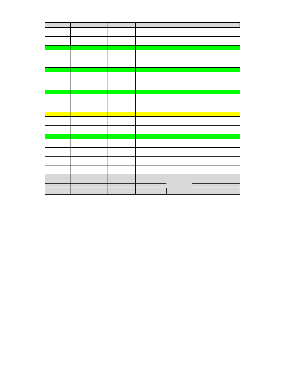
P4 Pin Signal Type Description P1, P2, P3 Correlation
B39 Analog In Ch13 Analog Analog Input Chan 13 (SE)
A40 Analog In Ch5 Analog Analog Input Chan 5 (SE)
B40 Ground Analog Analog Signal Common Multiple, see P1, P2, P3
A41 Analog In Ch12 Analog Analog Input Chan 12 (SE)
B41 Analog In Ch 4 Analog Analog Input Chan 4 (SE)
A42 Ground Analog Analog Signal Common Multiple, see P1, P2, P3
B42 Analog In Ch11 Analog Analog Input Chan 11 (SE)
A43 Analog In Ch3 Analog Analog Input Chan 3 (SE)
B43 Ground Analog Analog Signal Common Multiple, see P1, P2, P3
A44 Analog In Ch10 Analog Analog Input Chan 10 (SE)
B44 Analog In Ch2 Analog Analog Input Chan 2 (SE)
A45 Signal Ground Analog Sense Common (SGND) P1-19
B45 Analog In Ch9 Analog Analog Input Chan 9 (SE)
A46 Analog In Ch1 Analog Analog Input Chan 1 (SE)
B46 Ground Analog Analog Signal Common Multiple, see P1, P2, P3
A47 Analog In Ch8 Analog Analog Input Chan 8 (SE)
B47 Analog In Ch0 Analog Analog Input Chan 0 (SE)
A48 -15VDC Power Expansion -15 Volts P1 pin 2
B48 +15VDC Power Expansion +15 Volts P1 pin 21
A49 * DAC 0 Analog DAC 0 Output P3 pin 34
B49 *
A50 * DAC 1 Analog DAC 1 Output P3 pin 33
B50 *
DAC 2 Analog DAC 2 Output P3 pin 32
DAC 3 Analog DAC 3 Output
Analog Input Chan 5L (DIF)
Analog Input Chan 5H (DIF)
Analog Input Chan 4L (DIF)
Analog Input Chan 4H (DIF)
Analog Input Chan 3L (DIF)
Analog Input Chan 3H (DIF)
Analog Input Chan 2L (DIF)
Analog Input Chan 2H (DIF)
Analog Input Chan 1L (DIF)
Analog Input Chan 1H (DIF)
Analog Input Chan 0L (DIF)
Analog Input Chan 0H (DIF)
Requires a
DBK46 to
be
Installed.
P1 pin 13
P1 pin 32
P1 pin 14
P1 pin 33
P1 pin 15
P1 pin 34
P1 pin 16
P1 pin 35
P1 pin 17
P1 pin 36
P1 pin 18
P1 pin 37
P3 pin 37
P3 pin 19
P3 pin 31
* DAC 0, DAC1, DAC2, and DAC 3 (from P4 pins A49, B49, A50, and B50, respectively) only apply to
the DaqBook/2000 Series Devices when a DBK46 plug-in card has been installed in the unit.
sc-8 System Connections & Pinouts
927196
DaqBook/2000 Series User’s Manual
Page 63
DBK200 Series, Selected P4 Connector Options
This section of the document pertains to DBK200 Series devices that are typically used when the P4 connection option is desired. For information regarding other DBK200 Series options, refer to the DBK Option
Cards and Modules User’s Manual (p/n 457-0905). A PDF version of the document is included on the data
acquisition CD.
If your acquisition system needs to be CE Compliant, read the Declaration of Conformity
for your DaqBook/2000 Series device and Chapter 3, CE Compliance prior to expanding
the acquisition system.
Reference Note: Prior to connecting a DBK to a DaqBook/2000 Series device, refer to the
applicable DBK document module(s), in the DBK Option Cards and Modules User’s Manual
(p/n 457-0905). ). A PDF version of the document is included on the data acquisition CD.
The P4 connector on a DaqBook/2000 Series device shares signal connections with the P1,
P2, and P3 connectors. P4 offers no additional I/O. Connecting a DBK200 Series Option
to P4 via a CA-195 cable distances the P1, P2, P3 connection from the DaqBook/2000
Series device. It does not provide any new signal I/O. See the following Caution.
CAUTION
DBK202, DBK203
DBK206
DBK207, DBK207/CJC
DBK208
Signal conflicts between a DaqBook/2000 Series device’s P1, P2, P3 connectors and its
P4 connector can result in erroneous readings and possible equipment damage.
Therefore, when connections have been made to P1, P2, and/or P3, use caution when
making connections through P4, and visa versa.
The previous pinouts indicate the P1, P2, and P3 pins, and their P4 equivalents. Use the
pinouts to avoid making duplicate signal connections.
There are two ways to connect a DBK option to a DaqBook/2000 Series device. The first
method is preferable, as it introduces less noise.
Preferred Method – (a) Connect a CA-37-x cable to the appropriate DB37 connector
[P1, P2, or P3] on the DaqBook/2000 Series device. (b) Connect the
free end of the cable to the DBK card or module.
Optional Method – (a) Connect a CA-195-x cable to the P4 connector on the
DaqBook/2000 Series device. (b) Connect the free end of the cable
to a DBK200 Series device. (c) Connect the DBK option to the
DBK200 Series device, as applicable.
The primary reason that less noise is seen in the “preferred” method is that a
DaqBook/2000 Series device’s P1 connector pertains only to analog acquisition signals
and the P2 connector pertains only to digital I/O. This provides a strong degree of
isolation between the two signal types. However, in the case of a CA-195-x cable
connected to P4, digital and analog signals co-exist in one cable.
If you need to use the P4 connection method, use of the 8-inch ribbon cable (CA-195-1)
will result in the lowest level of crosstalk [for that method].
DaqBook/2000 Series User’s Manual
927196
System Connections & Pinouts sc-9
Page 64
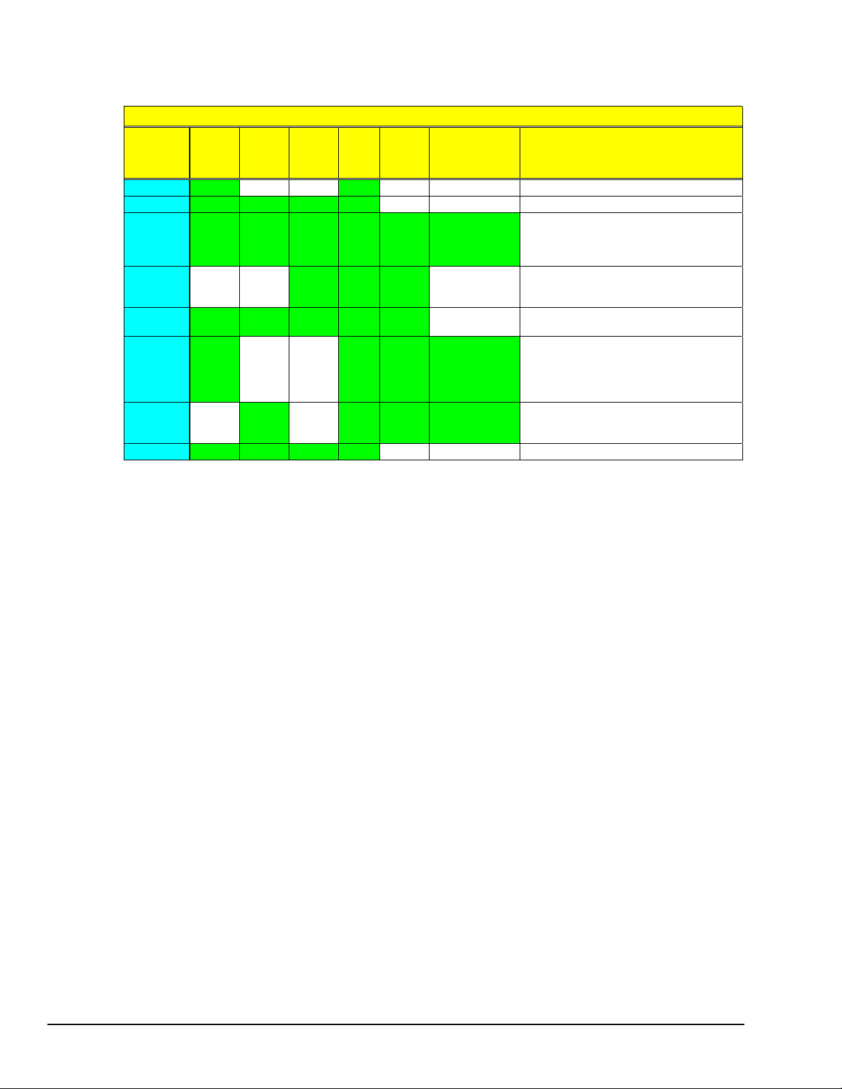
The following matrix provides a quick comparison of the DBK200 Series adapter boards. Details for each
board are provided in the DBK Option Cards and Modules User’s Manual (p/n 457-0905). An illustration and
brief discussion of selected adapter boards is presented after the following table.
DBK200 Series, Adapter Board Matrix
DBK P1
Analog
200
201
202
Yes
Yes Yes Yes Yes
Yes Yes 40-pin
203
204
205
206
207
207/CJC
208
209
No
Yes Yes Yes Yes Yes
Yes
(Qty. 2)
No
Yes Yes Yes Yes
Digital
No No
P2
P3
Pulse,
Freq.,
Digital
header
for P3
No
No
Yes
(Qty. 2)
12
screw-
term.
No
No
Screw
P4
Yes
Terminals
Special
Features
No No
No No
Yes Yes Custom RC
Filter Setup.
Yes Yes
No
No
Yes Yes Can carry
5B modules.
Yes Yes Can carry
relay modules.
No No
Comments
Analog I/O use only.
Like DBK209, except for form-factor.
DBK202 is a board only. DBK203
consists of a DBK202 mounted in a
chassis. DBK204 consists of a DBK203
and a CA-209 CE cable kit. *
Only used with DaqBoard/2003 or /2003c.
Can plug directly into P4. Screw terminals
are related to P3.
Similar to DBK202, but has a different
form-factor and has no RC filter setup.
Supports 5B-compatible Analog I/O
modules. DBK207/CJC includes Cold
Junction Compensation. Includes two P1
connectors. Screw terminals are for 5B
module connections.
Supports Opto-22 compatible Solid-StateRelay (SSR) digital modules. Includes two
P2 connectors.
Like DBK201, except for form-factor.
• Cable Kit CA-209 CE, which is included with DBK204, does not apply to DaqBook/2000 Series devices.
Refer to chapter 3, CE Compliance, for detailed information.
sc-10 System Connections & Pinouts
927196
DaqBook/2000 Series User’s Manual
Page 65
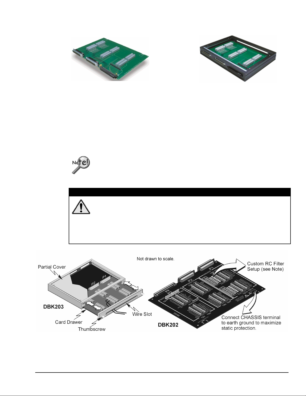
DBK202 and DBK203
DBK202
P4-to-P1/P2/P3 Adapter with Screw-Terminals
and Locators for RC Filter Setup
DBK203, with Cover Plate Removed
Chassis-Mounted P4-to-P1/P2/P3 Adapter with
Screw-Terminals and Locators for RC Filter Setup
DBK203 Screw-Terminal Adapter Module
The DBK203 consists of a DBK202 board that is mounted to a card drawer. DBK203’s card drawer is
housed in a shielded metal enclosure; and can be slid free of the module. The sliding card drawer provides
easy access to the board’s twelve terminal blocks and to the 40-pin P3 header. Note that the DBK203
modules can be easily mounted to other DBK modules via fastener panels that are included in splice plate
kits.
The P4 connector on a DaqBook/2000 Series device shares signal connections with the P1,
P2, and P3 connectors. P4 offers no additional I/O. Connecting a DBK200 Series Option
to P4 via a CA-195 cable distances the P1, P2, P3 connection from the DaqBook/2000
Series device. It does not provide any new signal I/O. See the following Caution.
CAUTION
Signal conflicts between a DaqBook/2000 Series device’s P1, P2, P3 connectors and its
P4 connector can result in erroneous readings and possible equipment damage.
Therefore, when connections have been made to P1, P2, and/or P3, use caution when
making connections through P4, and visa versa.
The previous pinouts indicate the P1, P2, and P3 pins, and their P4 equivalents. Use the
pinouts to avoid making duplicate signal connections.
DaqBook/2000 Series User’s Manual
DBK203 Includes a Slide-Out Draw with a DBK202 Board
927196
System Connections & Pinouts sc-11
Page 66

Reference Note:
You can install resistors and capacitors to create RC networks for P1’s Analog Input Channels.
Refer to the DBK203 section of the DBK Option Cards and Modules User’s Manual
(p/n 457-0905) for details. A PDF version of the document is included on the data acquisition
CD.
The DBK202 and DBK203 adapters each provide a DB37 P1 connector, DB37 P2 connector, and a 40-pin
header (designated as P3).
P1 is used for ANALOG I/O •
• • P2 for DIGITAL I/O
P3 for Pulse/Frequency (Digital and Counter/Timer) I/O
In addition to the P1, P2, and P3 connectors, these boards include terminal blocks designated TB1 through
TB12. The blocks provide a screw-terminal connection option for P1, P2, and P3.
Each of the three adapters can be connected to the DaqBook/2000 Series Device’s 100-pin P4 connector
via a CA-195 cable.
Note: These screw-terminal adapter boards provide a means of connecting signals to a DaqBook/2000
Series Device via one of three methods:
•
Cables connected to the DBK202 [or DBK203] P1, P2, and P3 connectors, as applicable.
•
Signal wires connected to the appropriate screw-terminal blocks (TB1 through TB12).
The board’s silkscreen identifies all screw terminals.
•
A combination of the above two methods.
sc-12 System Connections & Pinouts
927196
DaqBook/2000 Series User’s Manual
Page 67
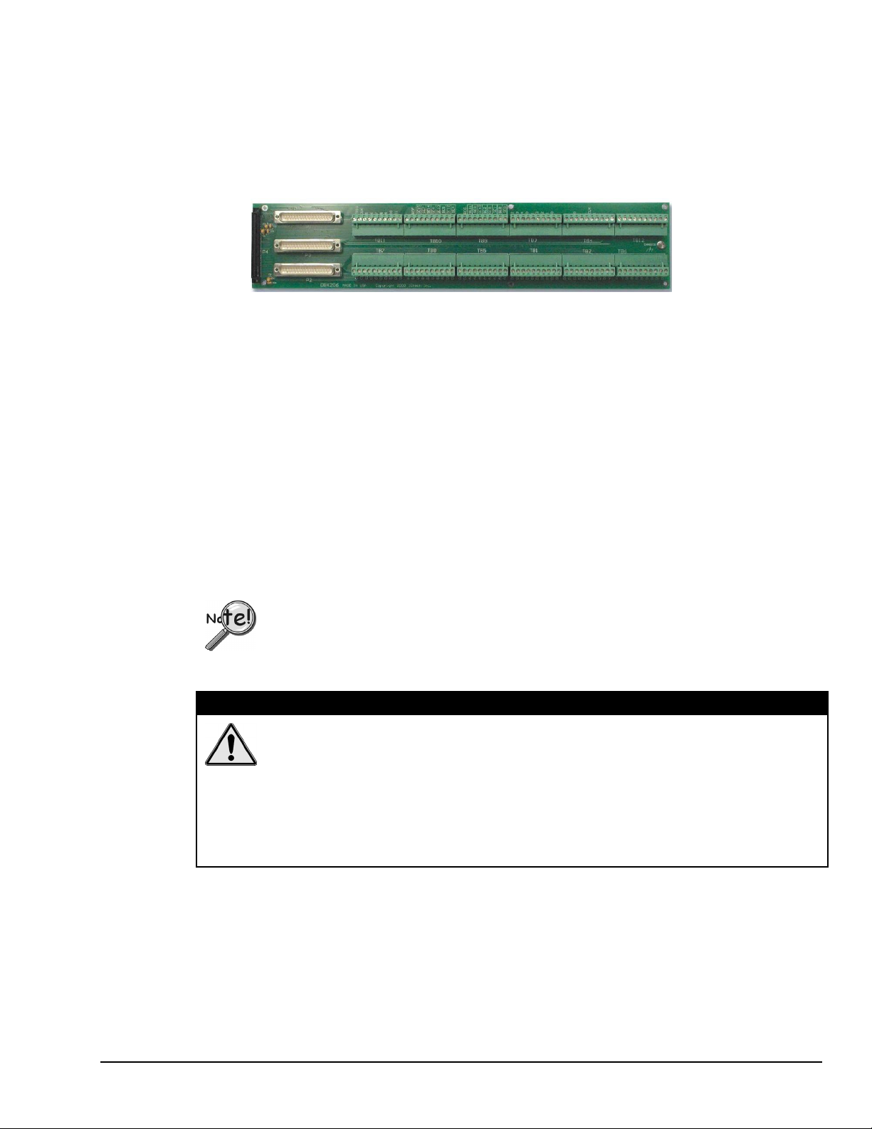
DBK206
The DBK206 provides a P1, P2, and P3 connector and corresponding screw-terminal blocks.
P1 is used for ANALOG I/O •
• • P2 for DIGITAL I/O
P3 for Pulse/Frequency (Digital and Counter/Timer) I/O
DBK206, P4-to-P1/P2/P3 Adapter with Screw-Terminals
The DBK206 is suitable for both analog and digital expansion. Signal connection to a DaqBook/2000
Series Device can be made as follows:
• With cables connected to P1, P2, and P3 connectors, as applicable.
• With signal wires connected to the appropriate screw-terminal blocks (TB1 through TB12).
Note that the DBK206 board’s silkscreen identifies all screw terminals.
• With a combination of the above two methods.
Regardless of which method is used, the DBK206 connects to the 100-pin P4 connector of the
DaqBook/2000 Series Device. The connection is made via a CA-195 cable. The board contains mounting
holes that allow the board to be secured inside a user-provided enclosure.
Note: Terminal block correlation to P1, P2, and P3 is provided on the next three pages.
The P4 connector on a DaqBook/2000 Series device shares signal connections with the P1,
P2, and P3 connectors. P4 offers no additional I/O. Connecting a DBK200 Series Option
to P4 via a CA-195 cable distances the P1, P2, P3 connection from the DaqBook/2000
Series device. It does not provide any new signal I/O. See the following Caution.
CAUTION
Signal conflicts between a DaqBook/2000 Series device’s P1, P2, P3 connectors and its
P4 connector can result in erroneous readings and possible equipment damage.
Therefore, when connections have been made to P1, P2, and/or P3, use caution when
making connections through P4, and visa versa.
The previous pinouts indicate the P1, P2, and P3 pins, and their P4 equivalents. Use
those pinouts and the related terminal block pinouts [which follow] to avoid making
duplicate signal connections.
DaqBook/2000 Series User’s Manual
927196
System Connections & Pinouts sc-13
Page 68
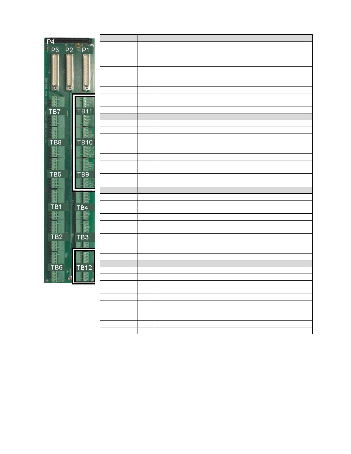
DBK206: TB Correlation to P1 – Applies to TB11, TB10, TB9, and TB12 for Analog I/O.
TB11 P1 Pin Number and Description
TTL TRIG 25 TTL Trigger, Digital IN, External TTL Trigger Input
A/I CLK 20 A/I Clock, External ADC Pacer Clock Input/
EXP 5 5 Expansion 5. Digital OUT, external GAIN select bit 1
EXP 6 6 Expansion 6. Digital OUT, external GAIN select bit 0
EXP 7 3 Expansion 7. Digital OUT, external ADDRESS, select bit 3
EXP 8 22 Expansion 8. Digital OUT, external ADDRESS, select bit 2
EXP 9 4 Expansion 9. Digital OUT, external ADDRESS, select bit 1
EXP 10 23 Expansion 10. Digital OUT, external ADDRESS, select bit 0
EXP 11 26 Expansion 11. Simultaneous Sample and Hold (SSH)
AGND * Common Ground
TB10 P1 Pin Number and Description
SGND 19 Signal Ground, Sense Common
POSREF 9 Positive Reference, Analog +5 V reference
SE15 11 CH 15 IN (Single-Ended Mode) / CH 7 LO IN (Differential Mode)
SE7 30 CH 7 IN (Single-Ended Mode) / CH 7 HI IN (Differential Mode)
SE14 12 CH 14 IN (Single-Ended Mode) / CH 6 LO IN (Differential Mode)
SE6 31 CH 6 IN (Single-Ended Mode) / CH 6 HI IN (Differential Mode)
SE13 13 CH 13 IN (Single-Ended Mode) / CH 5 LO IN (Differential Mode)
SE5 32 CH 5 IN (Single-Ended Mode) / CH 5 HI IN (Differential Mode)
SE12 14 CH 12 IN (Single-Ended Mode) / CH 4 LO IN (Differential Mode)
SE4 33 CH 4 IN (Single-Ended Mode) / CH 4 HI IN (Differential Mode)
TB9 P1 Pin Number and Description
SGND 19 Signal Ground, Sense Common
NEGREF 8 Negative Reference, Analog -5 V reference
SE11 15 CH 11 IN (Single-Ended Mode) / CH 3 LO IN (Differential Mode)
SE3 34 CH 3 IN (Single-Ended Mode) / CH 3 HI IN (Differential Mode)
SE10 16 CH 10 IN (Single-Ended Mode) / CH 2 LO IN (Differential Mode)
SE2 35 CH 2 IN (Single-Ended Mode) / CH 2 HI IN (Differential Mode)
SE9 17 CH 9 IN (Single-Ended Mode) / CH 1 LO IN (Differential Mode)
SE1 36 CH 1 IN (Single-Ended Mode) / CH 1 HI IN (Differential Mode)
SE8 18 CH 8 IN (Single-Ended Mode) / CH 0 LO IN (Differential Mode)
SE0 37 CH 0 IN (Single-Ended Mode) / CH 0 HI IN (Differential Mode)
TB12 P1 Pin Number and Description
AGND * Common Ground
AGND * Common Ground
AGND * Common Ground
AGND * Common Ground
AGND * Common Ground
AGND * Common Ground
+ 15 V 21 Expansion, +15 V Power
- 15 V 2 Expansion, -15 V Power
AGND * Common Ground
+ 5 V 1 Expansion, +5 V Power
* In regard to the P1-related grounds, refer to the P1 pinout on page sc-3.
Internal ADC Pacer Clock Output
sc-14 System Connections & Pinouts
927196
DaqBook/2000 Series User’s Manual
Page 69
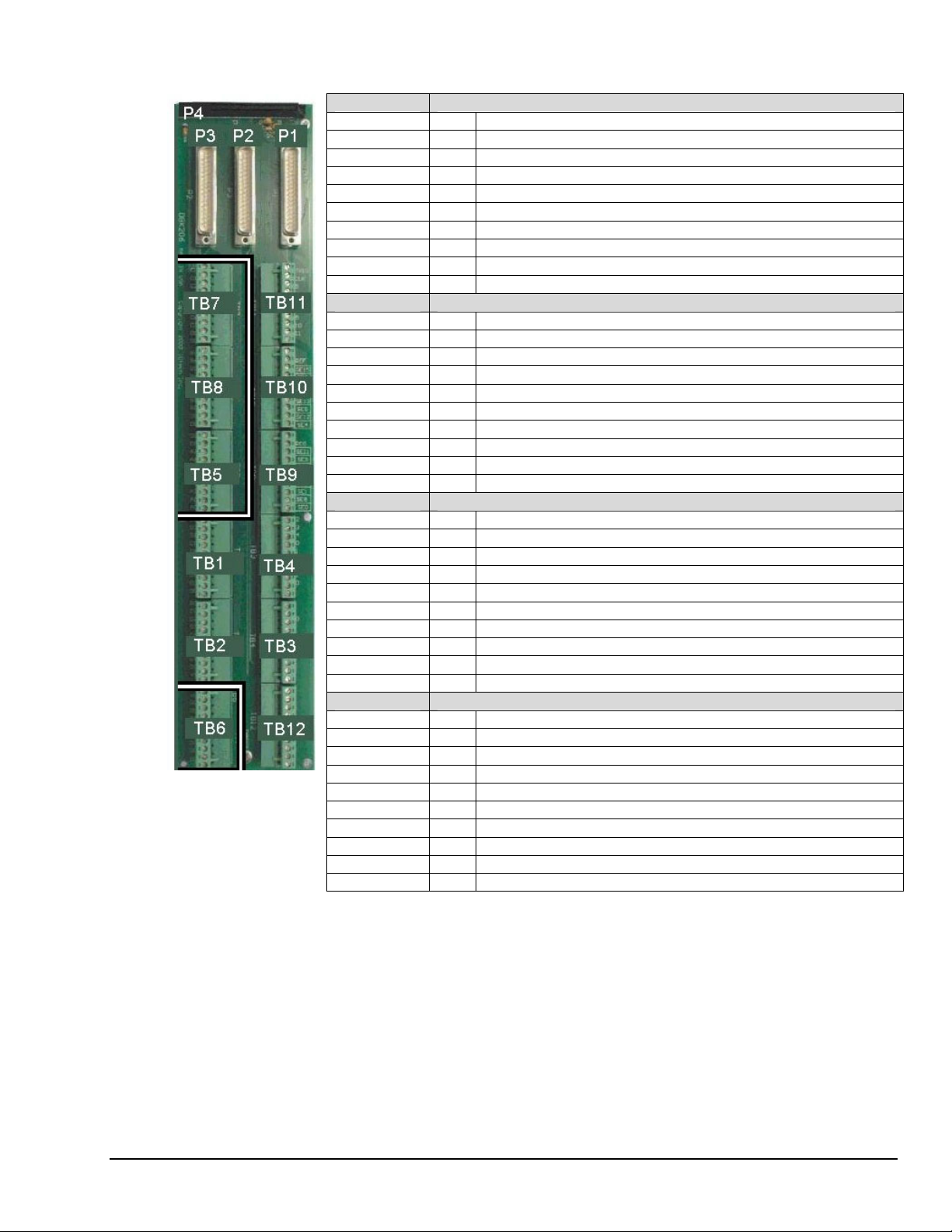
DBK206: TB Correlation to P2 – Applies to TB5, TB6, TB7, and TB8 for Digital I/O.
TB7 P2 Pin Number and Description
C0 29 Digital I/O: P2, Digital Port C, Bit 0; or P2 Expansion Data Bit 0
C1 28 Digital I/O: P2, Digital Port C, Bit 1; or P2 Expansion Data Bit 1
C2 27 Digital I/O: P2, Digital Port C, Bit 2; or P2 Expansion Data Bit 2
C3 26 Digital I/O: P2, Digital Port C, Bit 3; or P2 Expansion Data Bit 3
C4 25 Digital I/O: P2, Digital Port C, Bit 4; or P2 Expansion Data Bit 4
C5 24 Digital I/O: P2, Digital Port C, Bit 5; or P2 Expansion Data Bit 5
C6 23 Digital I/O: P2, Digital Port C, Bit 6; or P2 Expansion Data Bit 6
C7 22 Digital I/O: P2, Digital Port C, Bit 7; or P2 Expansion Data Bit 7
DGND * Digital Common
DGND * Digital Common
TB8 P2 Pin Number and Description
B7 3 Digital I/O: P2, Digital Port B, Bit 7; or P2 Expansion Address Bit 0 Out
B6 4 Digital I/O: P2, Digital Port B, Bit 6; or P2 Expansion Address Bit 1 Out
B5 5 Digital I/O: P2, Digital Port B, Bit 5; or P2 Expansion Address Bit 2 Out
B4 6 Digital I/O: P2, Digital Port B, Bit 4; or P2 Expansion Address Bit 3 Out
B3 7 Digital I/O: P2, Digital Port B, Bit 3; or P2 Expansion Address Bit 4 Out
B2 8 Digital I/O: P2, Digital Port B, Bit 2; or P2 Expansion RESET Output
B1 9 Digital I/O: P2, Digital Port B, Bit 1; or P2 Expansion WRITE Output
B0 10 Digital I/O: P2, Digital Port B, Bit 0; or P2 Expansion READ Output
DGND * Digital Common
DGND * Digital Common
TB5 P2 Pin Number and Description
DGND * Digital Common
DGND * Digital Common
A7 30 Digital I/O: P2, Digital Port A, Bit 7; or P2 Expansion Data Bit 15
A6 31 Digital I/O: P2, Digital Port A, Bit 6; or P2 Expansion Data Bit 14
A5 32 Digital I/O: P2, Digital Port A, Bit 5; or P2 Expansion Data Bit 13
A4 33 Digital I/O: P2, Digital Port A, Bit 4; or P2 Expansion Data Bit 12
A3 34 Digital I/O: P2, Digital Port A, Bit 3; or P2 Expansion Data Bit 11
A2 35 Digital I/O: P2, Digital Port A, Bit 2; or P2 Expansion Data Bit 10
A1 36 Digital I/O: P2, Digital Port A, Bit 1; or P2 Expansion Data Bit 9
A0 37 Digital I/O: P2, Digital Port A, Bit 0; or P2 Expansion Data Bit 8
TB6 P2 Pin Number and Description
+5 V 18 Expansion +5 V Power
+5 V 20 Expansion +5 V Power
DGND * Digital Common
DGND * Digital Common
DGND * Digital Common
DGND * Digital Common
DGND * Digital Common
DGND * Digital Common
DGND * Digital Common
DGND * Digital Common
* In regard to the P2-related grounds, refer to the P2 pinout on page sc-4.
DaqBook/2000 Series User’s Manual
927196
System Connections & Pinouts sc-15
Page 70
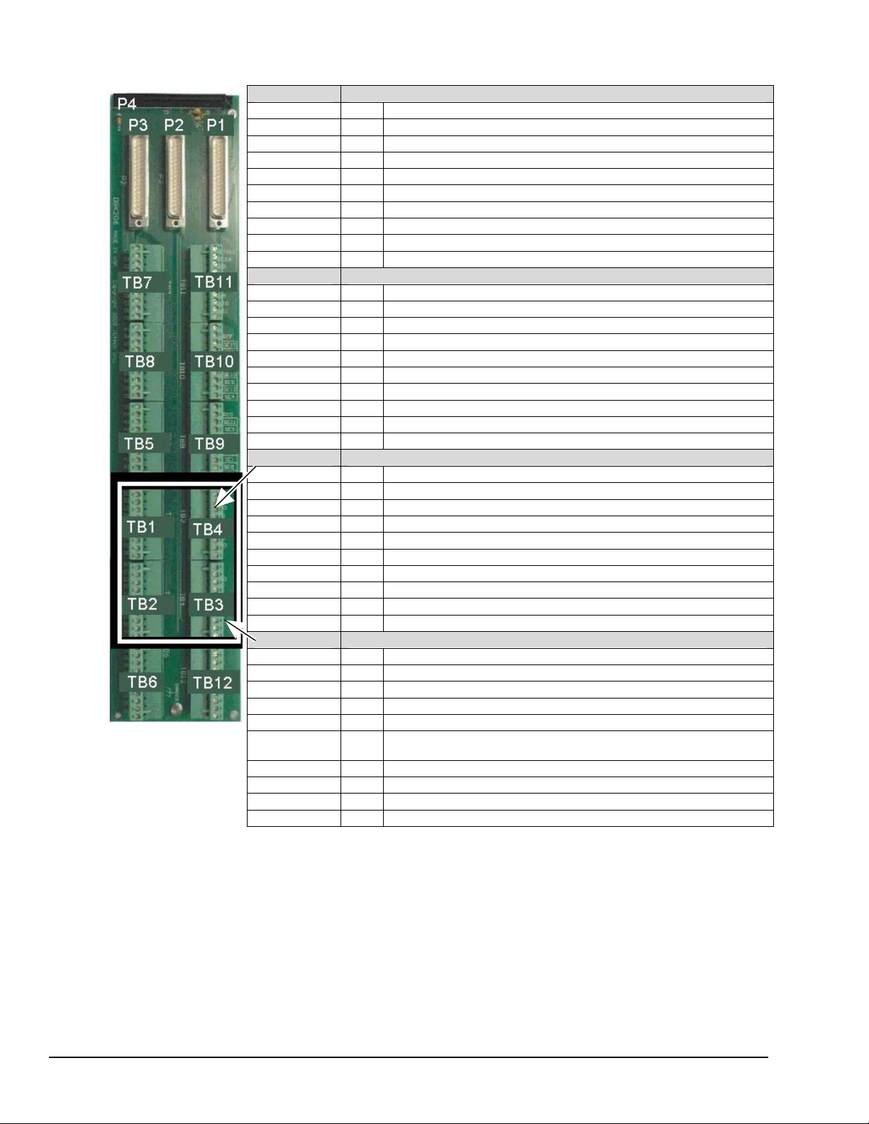
DBK206: TB Correlation to P3 – Applies to TB1, TB2, TB3, and TB4 for Pulse/Frequency/Digital I/O.
TB1 P3 Pin Number and Description
D8 29 P3 Digital Port Bit 8
D9 28 P3 Digital Port Bit 9
D10 27 P3 Digital Port Bit 10
D11 26 P3 Digital Port Bit 11
D12 25 P3 Digital Port Bit 12
D13 24 P3 Digital Port Bit 13
D14 23 P3 Digital Port Bit 14
D15 22 P3 Digital Port Bit 15
DGND * Digital Common
DGND * Digital Common
TB2 P3 Pin Number and Description
D0 10 P3 Digital Port Bit 0
D1 9 P3 Digital Port Bit 1
D2 8 P3 Digital Port Bit 2
D3 7 P3 Digital Port Bit 3
D4 6 P3 Digital Port Bit 4
D5 5 P3 Digital Port Bit 5
D6 4 P3 Digital Port Bit 6
D7 3 P3 Digital Port Bit 7
DGND * Digital Common
+5V 20 Expansion, +5 Volt Power
TB4 P3 Pin Number and Description
EXP 2 12 Reserved
EXP 3 13 Reserved
EXP 4 14 Reserved
TMR 0 15 P3 Timer 0 Output
TMR 1 16 P3, Timer 1 Output
CNT 3 35 P3 Counter 3 Input
CNT 2 17 P3 Counter 2 Input
CNT 1 36 P3 Counter 1 Input
CNT0 18 P3 Counter 0 Input
DGND * Digital Common
TB3 P3 Pin Number and Description
DAC0 34 Analog Out; Analog DAC 0 Output
DGND * Digital Common
DAC2 32 Analog Out; Analog DAC 2 Output
DGND * Digital Common
DAC1 33 Analog Out; Analog DAC 1 Output
A/O CLK 21 Analog Out Clock; External DAC Pacer Clock Input/
Internal DAC Pacer Clock Output
DAC3 31 Analog Out; Analog DAC 3 Output
DGND * Digital Common
+15 V 19 Expansion, + 15 VDC
-15 V 37 Expansion, -15 VDC
*In regard to P3-related grounds, refer to the P3 pinout on page sc-5.
sc-16 System Connections & Pinouts
927196
DaqBook/2000 Series User’s Manual
Page 71
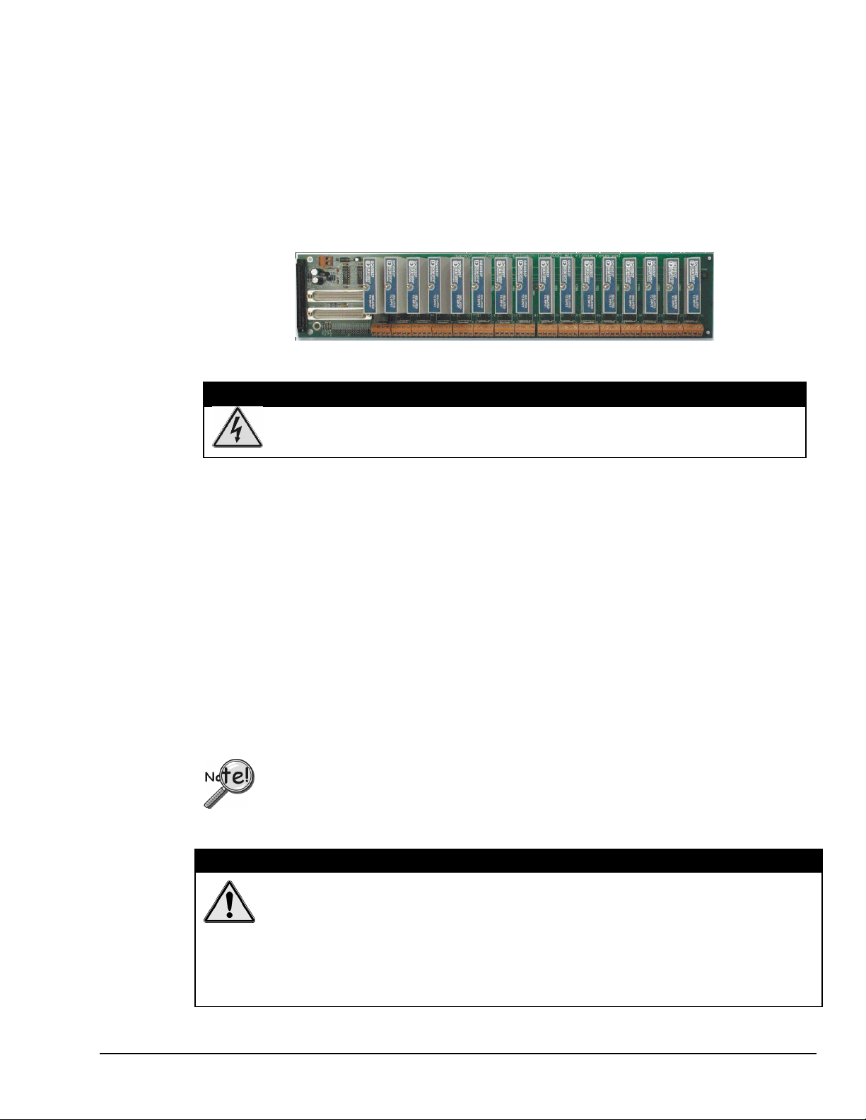
DBK207 and DBK207/CJC
The DBK207 and DBK207/CJC are carrier boards for 5B-compatible analog input modules. They
each provide:
•
two P1 connectors – for ANALOG I/O
•
a 5 VDC power terminal
•
footprints for sixteen 5B Modules
•
16 terminal blocks.
In addition, DBK207/CJC provides Cold Junction Compensation. The DBK207 and DBK207/CJC
each include a 100-pin P4 connector for use with DaqBook/2000 Series Devices.
DBK207/CJC Carrier Board for 5B Compatible Modules
WARNING
Ensure that hard-wire emergency over-ride circuitry exists for all applications that
make use of dangerous switch-loads. Do not operate such switch-loads unless
emergency over-ride circuitry is present.
DBK207 and DBK207/CJC are typically installed in NEMA-type panels; however, they may be installed
on DIN rails. Separate mounting instructions are included with Rack Mount Kit (part no. Rack-DBK-3)
and with DIN-rail Mount Kit (part no. DIN-DBK-1).
DBK207 and DBK207/CJC allow Daq-based acquisition systems to use various combinations of sixteen
5B signal-conditioning modules. 5B modules can accommodate a variety of signals, including low-level
thermocouple and strain-gage signals. Configuration options are flexible. You can select the type of signal
attached to each channel. One Daq device can support up to 16 DBK207 [or DBK207/CJC] boards,
providing a maximum of 256 isolated, analog input channels. Note that Daq devices scan the channels at
the same 10 µs/channel rate as other DBKs (256 scans in 2.56 ms in a full system).
Each user-installed 5B module offers 500 V isolation from the system and between channels. Both
DBK207 and DBK207/CJC include 16 screw-terminal blocks for signal inputs. In addition, the
DBK207/CJC includes cold junction compensators (CJCs) for use with thermocouple 5B modules.
Sockets are provided for user-installed AC1362 current-sense resistor modules, as discussed in
5B Module Connection in the DBK207 section of the DBK Option Cards and Modules User’s Manual
(p/n 457-0905). A PDF version of the document is included on the data acquisition CD.
The P4 connector on a DaqBook/2000 Series device shares signal connections with the P1,
P2, and P3 connectors. P4 offers no additional I/O. Connecting a DBK200 Series Option
to P4 via a CA-195 cable distances the P1, P2, P3 connection from the DaqBook/2000
Series device. It does not provide any new signal I/O. See the following Caution.
CAUTION
Signal conflicts between a DaqBook/2000 Series device’s P1, P2, P3 connectors and its
P4 connector can result in erroneous readings and possible equipment damage.
Therefore, when connections have been made to P1, P2, and/or P3, use caution when
making connections through P4, and visa versa.
The previous pinouts indicate the P1, P2, and P3 pins, and their P4 equivalents. Use the
pinouts to avoid making duplicate signal connections.
DaqBook/2000 Series User’s Manual
927196
System Connections & Pinouts sc-17
Page 72
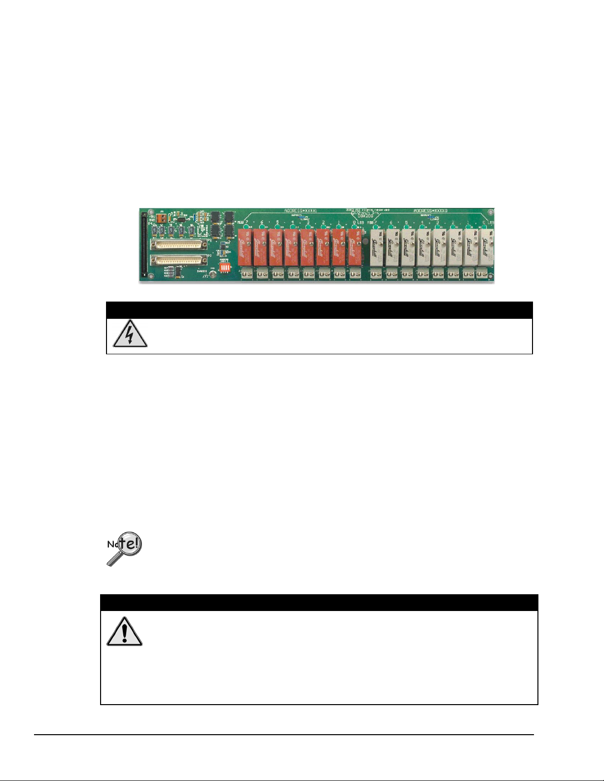
DBK208
DBK208 is a two-bank carrier board for optically-isolated Solid-State-Relay (SSR) modules. Each
bank supports up to eight digital I/O modules. The banks can be independently set as “input” or
“output” via jumpers (JP0 for Bank 0, and JP1 for Bank 1). The I/O modules are industry standard
Opto-22 compatible, 5-volt logic level modules.
The DBK208 includes:
• • two P2 connectors for DIGITAL I/O
footprints for sixteen optically-isolated Solid-State-Relay (SSR) Modules
• 16 dual-screw terminal blocks
• a 100-pin P4 connector
DBK208 Carrier Board for Opto-22 Compatible Solid-State-Relays
WARNING
Ensure that hard-wire emergency over-ride circuitry exists for all applications that
make use of dangerous switch-loads. Do not operate such switch-loads unless
emergency over-ride circuitry is present.
DBK208 boards are typically installed in NEMA-type panels; however, they may alternatively be installed
on DIN rails. Separate mounting instructions are included with Rack Mount Kit (part no. Rack-DBK-3)
and with DIN-rail Mount Kit (part no. DIN-DBK-1).
Connection of these devices to DBK208 can be made directly or indirectly as follows:
• Connection can be made from the DaqBook/2000 Series device P2 connector to a DBK208
P2 connector via a CA-37 cable.
• Connection can be made from the DaqBoook/2000 Series Device 100-pin P4 connector to a
DBK208’s P4 connector via a CA-195 cable.
Note that a single Daq-based data acquisition system can support up to 16 DBK208 boards, providing a
total of 256 channels. DBK208 boards contain two DB37 P2 connectors for the purpose of daisy-chaining
to other DBK208s or to other P2-supported devices.
The P4 connector on a DaqBook/2000 Series device shares signal connections with the P1,
P2, and P3 connectors. P4 offers no additional I/O. Connecting a DBK200 Series Option
to P4 via a CA-195 cable distances the P1, P2, P3 connection from the DaqBook/2000
Series device. It does not provide any new signal I/O. See the following Caution.
CAUTION
Signal conflicts between a DaqBook/2000 Series device’s P1, P2, P3 connectors and its
P4 connector can result in erroneous readings and possible equipment damage.
Therefore, when connections have been made to P1, P2, and/or P3, use caution when
making connections through P4, and visa versa.
The previous pinouts indicate the P1, P2, and P3 pins, and their P4 equivalents. Use the
pinouts to avoid making duplicate signal connections.
sc-18 System Connections & Pinouts
927196
DaqBook/2000 Series User’s Manual
Page 73

Operational Overview 1
Daq Systems, the Modular Concept …… 1-1
Block Diagram and Basic Features …… 1-3
Scanning …… 1-6
Triggering …… 1-7
Synchronous I/O Operations…… 1-8
Asynchronous I/O Operations …… 1-12
Using DBK Cards and Modules for Signal Conditioning ….. 1-13
Daq Software ……1-13
Daq Systems, the Modular Concept
Daq equipment and software form a modular, interrelated family of products that provide great flexibility in
data acquisition system design. This flexibility allows for the development of custom systems that are
unique to the user, and which can be optimized for his or her specific application needs. With the Daq
product line, system expansion or redesign can typically be accomplished with relative ease.
• Primary Acquisition Device. This is the main data acquisition device, e.g., a DaqBook, DaqBoard, or
Daq PC-Card. These devices provide a vital data conversion and communications link between the
data source of transducers and signal conditioners and the data processor of the host computer. Note
the DaqBoards can be one of three types: (1) ISA, (2) PCI, or (3) compact-PCI.
• DBK Option Cards and Modules. A variety of DBK cards and modules are available for system
expansion and to provide signal-conditioning options. Note that certain DBK modules exist for the
purpose of supplying power to other members of the acquisition system. The DBK options are
discussed in a DBK Basics document module and in the detailed DBK Option Cards and User’s
Manual (p/n 457-0905).
Note: Only passive DBKs, such as the DBK1 BNC module, the DBK11A screw terminal card, and
the DBK40 BNC analog interface, can be used with a Daq PC-Cards.
Reference Notes:
DBK options are discussed in the DBK Option Cards and Modules User’s Manual
(p/n 457-0905). As a part of product support, an Adobe PDF version of the manual is
automatically loaded onto your hard drive during software installation. The default
location is the Programs group, which can be accessed through the Windows Desktop.
Note that our PDF documents can be read directly from the CD. To use this feature:
When the CD’s opening screen appears, click the <View PDFs> button; then select the
desired document from the scroll list. The documents are read using the Adobe Acrobat
Reader. A copy of the reader is included on the CD.
• Software. DaqView out-of-the-box software provides a graphical user interface with easy to read
spreadsheet formats for viewing channel data, as well as a choice of analog, digital, and bar-graph
meters. Waveform analysis can be performed, when applicable. A product support option, included
on the data acquisition CD, provides a means of performing post data analysis. More information is
included in the software-specific PDF documents that are installed on your hard-drive as a part of
product support.
DaqBook/2000 Series User’s Manual
878897
Operational Overview 1-1
Page 74

In addition to the included out-of-the-box software, Daq products can be controlled via user-written
custom programs through Applications Program Interface (API). Several languages are supported,
e.g., C/C++, VisualBASIC, Delphi.
DaqView and DASYLab can only be used with one DaqBook/2000 Series Device at
a time. LabVIEW can be used with multiple devices. For multiple device use
(via custom programming) refer to the Using Multiple Devices section of the
Programmer’s Manual. During software installation from the data acquisition CD,
a PDF version of the Programmer’s Manual is automatically loaded onto your hard
drive as a part of product support. The default location is the Programs group.
Reference Note:
Programming topics are covered in the Programmer’s User Manual (p/n 1008-0901). As
a part of product support, this manual is automatically loaded onto your hard drive during
software installation. The default location is the Programs directory, which can be
accessed through the Windows Desktop.
1-2 Operational Overview
877997
DaqBook/2000 Series User’s Manual
Page 75
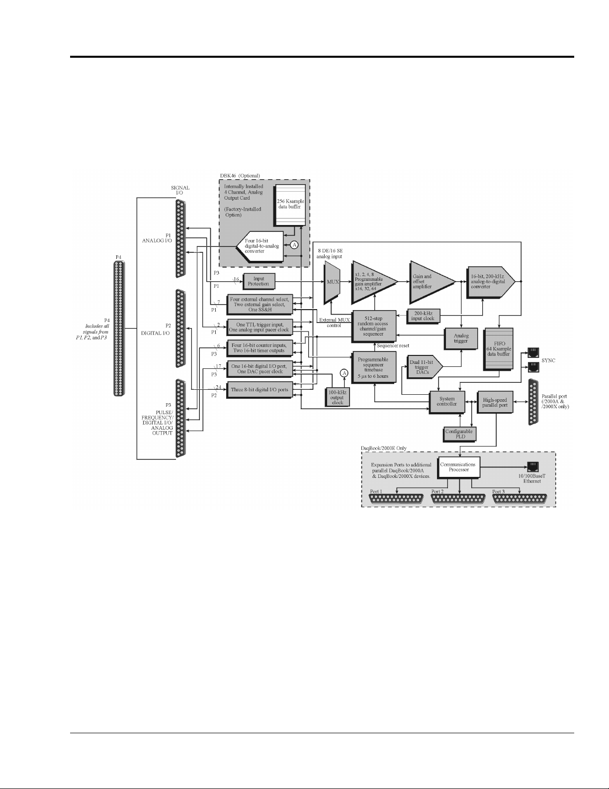
Block Diagram and Basic Features
DaqBook/2000 Series User’s Manual
DaqBook/2000 Series Block Diagram
877997
Daq Systems and Device Overviews 1-3
Page 76
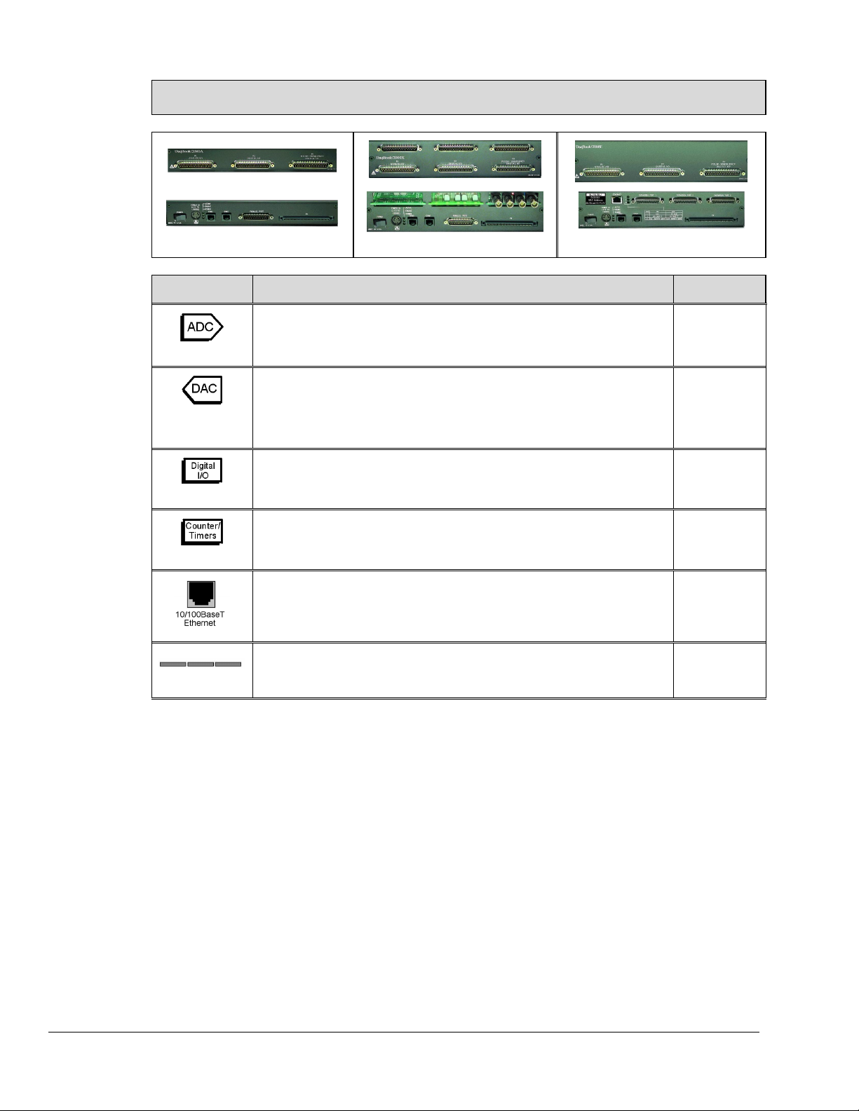
DaqBook/2000 Series, A Comparison of Device Features
DaqBook/2000A
Feature Description Applies to:
DaqBook/2000X
Analog Input Channels
Analog Input signals enter through P4 and P1, go to MUX, to PGA, to Gain &
16
Offset Amplifier, then to Analog-to-Digital Converter (ADC).
Analog Output Channels [Available only with DBK46 Option]
Digital Signals go through Digital-to-Analog Converters via the optional
4
(with DBK46)
DBK46 plug-in card, then through “DAC Out” on P4 and P3. The card
includes a 256K Sample Buffer. Note that the DBK46 option is a “Factory
Install” Option Only.
Digital I/O Channels
Digital signals pass through one 16-bit Digital I/O Port and three 8-bit Digital
40
I/O Ports located on P4, P3, and P2.
Counter/Timers
Four 16-bit Counter Input signals and Two 16-bit Timer Output signals via P4
6
and System Controller.
10/100BaseT Ethernet Interface located on the chassis
DaqBook/2000E includes a 10/100BaseT Ethernet interface. Note
The
DaqBook/2000E
All Models
Each model,
providing a
DBK46 is
installed.
All Models
All Models
/2000E
that DaqBook/2000A and DaqBook/2000X can connect to the
DaqBook/2000E, or to a WBK25 Ethernet module.
3 Card Exp.
3 Card Expansion
DaqBook/2000X includes three expansion slots that can accept a
The
wide variety of analog and digital DBK signal conditioning cards.
/2000X
DaqBook/2000 Series Devices are high-speed, multi-function, data acquisition systems for use with
notebook and desktop PCs. They feature a 16-bit, 200-kHz A/D converter, digital calibration, 40 digital
I/O lines, four counters, and two timers and, if the optional DBK46 card is installed, four 16-bit, 100-kHz
D/A converters
Up to 470 channels of analog and digital I/O can be accessed with one DaqBook/2000 Series Device.
All input and output signals are accessed via the three 37-pin DSUB connectors [P1, P2, and P3] located on
the front panel.
All I/O signals are also available on the rear panel via the 100-pin, P4 connector. P4 allows for optional
connection to a DBK200 Series Device for expansion from the rear panel.
1-4 Operational Overview
• P1 – Analog input port for16 single-ended or 8 differential analog inputs with 13 software
programmable ranges (±10 V to ±156 mV full scale).
• P2 – General purpose digital I/O port with 24 lines, or digital I/O expansion port controlling
up to 192 external lines.
• P3 – 16-bit digital I/O port, counter inputs, timer outputs, and analog outputs.
877997
DaqBook/2000 Series User’s Manual
Page 77

Each DaqBook/2000 Series Device’s internal on-board scan sequencer lets you select up to 512
channel/range combinations. The sequencer scans all channels of the scan at 5µs/channel, 10µs/channel,
or 1000µs/channel.
Note: All inputs [to a DaqBook/2000 Series device] can be measured at the 5 µs/channel rate. Some
DBK expansion options require more settling time and can be measured at the slower rate of
10 µs/channel or 1000 µs/channel. All types of measurements can be mixed within the scan group.
All DaqBook/2000 Series models have a 64K Sample Buffer. This allows analog and digital/counter input
data, as well as analog and digital output data, to flow from the PC to the DaqBook/2000 Series Device,
with no burden on the PC.
DaqBook/2000 Series Devices support a full complement of trigger modes including:
• Hardware analog triggering – A user-programmed trigger level sets an analog DAC, which
is compared in hardware to the analog input level on the selected channel. Trigger latency
is < 5 µs.
• Digital and pattern triggering – Every DaqBook/2000 Series Device has a separate digital
trigger input line, allowing TTL-level triggering and latencies less than 5 µs. The trigger can
be programmed for logic level or edge triggering. In pattern triggering, any of the digital input
ports acts as the trigger port. You can program the digital pattern.
• Software-based triggering – The PC detects the trigger event from readings, either analog,
digital, or counter. Six pre- and post-triggering modes are supported.
Multi-unit synchronization via the SYNC ports does not support pre-trigger data.
Only post-trigger data can be collected and time correlated between the units.
Other features include:
• 40 TTL-level digital I/O lines. They are divided into three 8-bit ports and one 16-bit port.
• Four 16-bit counters. Each can accept frequency inputs up to 10 MHz. The counters can be
cascaded into two 32-bit counters.
• Two 16-bit timer outputs. Each can generate square waves from 16 Hz to 1 MHz.
• Configuration through software only. All DaqBook/2000 device settings are made via
software. There are no hardware settings to be made, for example, there are no device DIP
switches to be set or jumpers to be positioned. However, note that DBK expansion options
may require s small degree of manual set up. Refer to the DBK Option Cards and Modules
User’s Manual (457-0905) for details. A PDF version of the document is included on the data
acquisition CD.
• Synchronization. Every DaqBook/2000 Series model includes two SYNC ports. The units
can be synchronized, with respect to each other, by connecting one DaqBook/2000 Series
device SYNC port to the SYNC port of a second DaqBook/2000 Series device. A unit can be
scan-synchronized and triggered from any other DaqBook/2000 Series that is connected to it
via a SYNC cable. Either one of a unit’s two sync ports, or both, can be used. A more
detailed discussion follows.
DaqBook/2000 Series User’s Manual
877997
Daq Systems and Device Overviews 1-5
Page 78
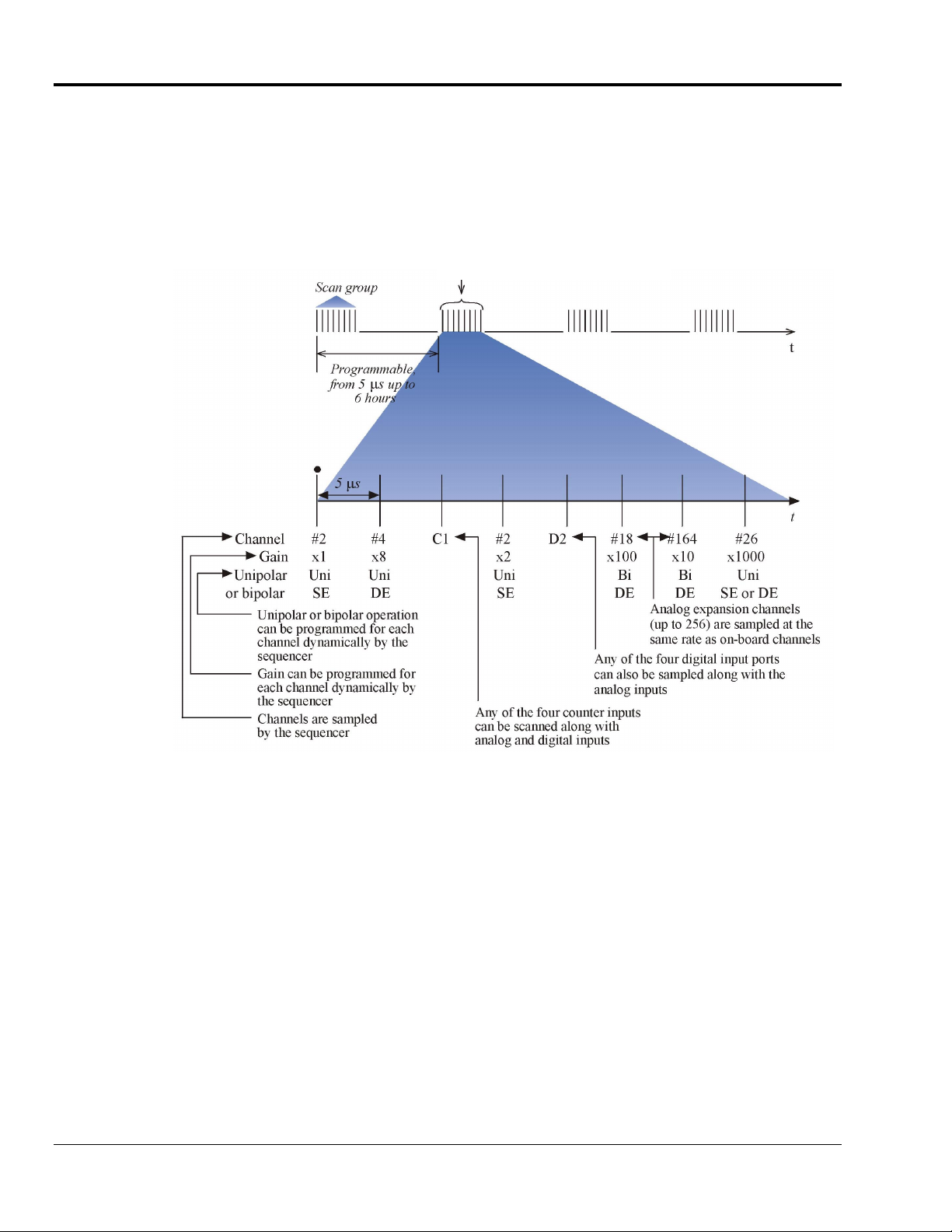
Scanning
Every DaqBook/2000 Series device has an on-board scan sequencer that permits the user to select any
combination of up to 512 channel/range combinations. The sequencer scans all channels contained in the
sequence at the rate of 5 µs/channel, 10 µs/channel, or 1000 µs/channel, depending on the speed of the
DBK expansion options; thereby minimizing the time-skew from channel-to-channel. The user can also set
the time between scan groups, from 0 to 6 hours. In addition to scanning analog inputs, the sequencer can
scan digital inputs and counter inputs.
Note: All inputs [to a DaqBook/2000 Series device] can be measured at the 5 µs/channel rate. Some
The 512-location scan sequencer allows you to select each channel and associated input amplifier gain. All
channels are scanned at 5 µs/channel, 10 µs/channel, or 1000 µs/channel, depending on the speed of the
DBK expansion options. In addition, the digital and frequency inputs can be scanned using the same scan
sequencer employed for analog inputs, enabling the time correlation of acquired digital data to acquired
analog data.
Each scan group, which can contain up to 512 channel/gain combinations, can be repeated immediately or
at programmable intervals of up to 6 hours. Within each scan group, consecutive channels are measured at
the fixed rate of 5 µs/channel, 10 µs/channel, or 1000 µs/channel.
1-6 Operational Overview
DaqBook/2000 Series, Scanning Example
DBK expansion options require more settling time and can be measured at the slower rate of
10 µs/channel or 1000 µs/channel. All types of measurements can be mixed within the scan group.
877997
DaqBook/2000 Series User’s Manual
Page 79

Triggering
Triggering can be the most critical aspect of acquiring data. DaqBook/2000 Series models support a full
complement of trigger modes to accommodate a wide variety of applications.
Multi-unit synchronization via the SYNC ports does not support pre-trigger data.
Only post-trigger data can be collected and time correlated between the units.
Hardware Analog Triggering. Many data acquisition products claim analog triggering, but rely on the
PC to take readings and make a decision, which leads to uncertain and potentially long latencies.
DaqBook/2000 Series devices use true analog triggering, whereby the trigger level programmed by the user,
sets an analog DAC, which is then compared in hardware to the analog input level on the selected channel.
The result is analog trigger latency that is guaranteed to be less than 5 µs, significantly shorter than most
data acquisition devices. Any analog channel can be selected as the trigger channel. The user can program
both the trigger level, as well as the edge (rising or falling).
Digital Triggering (P1). A separate digital trigger input line is provided, allowing TTL-level triggering,
again with latencies guaranteed to be less than 5 µs. Both the logic levels (1 or 0), as well as the edge (rising
or falling), can be programmed for the discrete digital trigger input. The digital trigger input is labeled
TTLTRG.
Digital Pattern Triggering (P2). All DaqBook/2000 Series models support digital pattern triggering,
whereby the user can designate any of the digital input ports as the trigger port. The programmed digital
pattern, including the ability to mask or ignore specific bits, is then compared to the actual input until a
match is detected, after which the sequencer begins the scan sequence.
Counter Triggering. Triggering can also be programmed to occur when one of the counters reaches,
exceeds, or is within a programmed level. Any of the built-in counter/totalizer channels can be programmed
as a trigger source.
Software-Based Triggering. Software-based triggering differs from the modes described above because
the readings, analog, digital, or counter, are interrogated by the PC to detect the trigger event, not in the
hardware as described above. The advantage of this mode is to permit triggering based on more complex
situations, such as on a specific temperature, which was derived from the acquisition of at least two analog
measurements, plus the calculation of the measured temperature using linearization algorithms.
Normally software-based triggering results in long latencies from the time that a trigger condition is
detected, until the actual capturing of data commences. However, the DaqBook/2000 Series circuitry
circumvents this undesirable phenomenon by use of pre-trigger data. Specifically, when software-based
triggering is employed, and the PC detects that a trigger condition has occurred, (which may be thousands
of readings later than the actual occurrence of the signal), the DaqBook/2000 Series driver automatically
looks back to the location in memory where the actual trigger-causing measurement occurred. The acquired
data that is presented to the user actually begins at the point where the trigger-causing measurement occurs.
The latency in this mode is equal to one scan cycle.
DaqBook/2000 Series User’s Manual
877997
Daq Systems and Device Overviews 1-7
Page 80
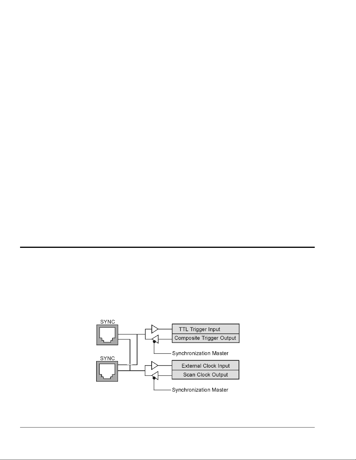
Pre- and Post-Triggering Modes. Six modes of pre- and post-triggering are supported, providing a wide
variety of options to accommodate any measurement requirement. When using pre-trigger, the user must use
software-based triggering to initiate an acquisition.
No pre-trigger, post-trigger stop event. This, the simplest of modes, acquires data upon
•
receipt of the trigger, and stops acquiring upon receipt of the stop-trigger event.
Fixed pre-trigger with post-trigger stop event. In this mode, the user specifies the number of
•
pre-trigger readings to be acquired, after which, acquisition continues until a stop-trigger event
occurs.
No pre-trigger, infinite post-trigger. No pre-trigger data is acquired in this mode. Instead,
•
data is acquired beginning with the trigger event, and is terminated when the operator issues a
command to halt the acquisition.
Fixed pre-trigger with infinite post-trigger. The user specifies the amount of pre-trigger data
•
to acquire, after which the system continues to acquire data until the program issues a
command to halt acquisition.
Variable pre-trigger with post trigger stop event (driver support only). Unlike the previous
•
pre-trigger modes, this mode does not have to satisfy the pre-trigger number of readings
before recognizing the trigger event. Thus the number of pre-trigger readings acquired is
variable and dependent on the time of the trigger event relative to the start. In this mode, data
continues to be acquired until the stop trigger event is detected.
Variable pre-trigger with infinite post trigger (driver support only). This is similar to the
•
mode just described, except that the acquisition is terminated upon receipt of a command from
the program.
Stop Trigger. Any of the software trigger modes described above can be used to stop an
•
acquisition. Thus an acquisition can be programmed to begin on one event, such as a
temperature level, and then stopped on another, such as a digital pattern event.
Synchronous I/O Operations
Synchronizing Multiple Units
All DaqBook/2000 Series units can be synchronized to other DaqBook/2000 Series units via their SYNC
ports. Each unit has two identical SYNC ports located on the rear panel. Either, or both SYNC ports can
be used to connect to the units via SYNC cables, CA-74-1 or CA-74-5 (1-foot or 5-foot cables,
respectively). The units can be scan-synchronized and triggered from any other SYNC-connected unit.
1-8 Operational Overview
Synchronization Concept Block Diagram
877997
DaqBook/2000 Series User’s Manual
Page 81
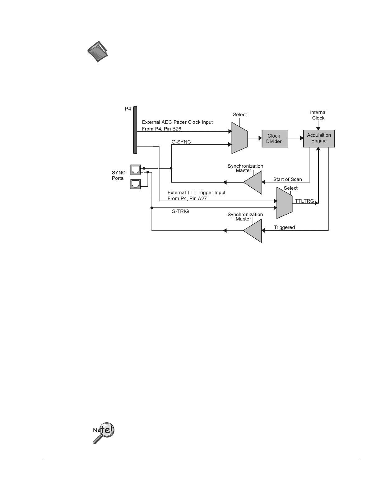
The preceding diagram shows how a DaqBook/2000 Series unit can input or output synchronization timing
and trigger events on either SYNC connector. A more detailed block diagram follows shortly.
Reference Note: The SYNC features are programmable via software. For detailed information
see the Using Multiple Devices and the daqAdcSetClockSource sections of the
Programmer’s Manual (p/n 1008-0901).
PDF NOTE:
During software installation, Adobe® PDF versions of user manuals automatically install onto
your hard drive as a part of product support. The default location is in the Programs group,
which can be accessed from the Windows Desktop. Refer to the PDF documentation for details
regarding both hardware and software.
Synchronization Model
The synchronization model illustrates the SYNC function that is available with DaqBook/2000 Series units.
In regard to synchronization, the following apply:
•
One of three signals can be used to drive the DaqBook/2000 Series device’s acquisition scan rate.
These are:
−
the internal acquisition pacer clock
−
an external acquisition pacer clock (from P1, pin 20 or P4, pin B26)
−
the global sync (G-SYNC) input from the SYNC ports on the rear panels
•
Both the SYNC connector input and the external clock input can be divided down.
•
When a DaqBook/2000 Series device is in the Master Mode, both the trigger condition and the
scan timing are output on the SYNC port. The global trigger (G-TRIG) is selected instead of
the TTL Trigger Input (from P4, Pin A27).
Whether the DaqBook/2000 Series device is using its internal scan clock, or external clock input, it can
be programmed to output the clock on the SYNC connector. In either case, the unit is behaving like a
synchronization master. Other DaqBook/2000 Series units [that are connected to the master, via a SYNC
port] should be programmed as synchronization slaves.
When a DaqBook/2000 Series device is programmed as a synchronization slave, it will derive its scan
period from the SYNC port. If the slave unit must be triggered at the same time as the master unit,
then the slave unit should use TTL Trigger as its trigger source.
Multi-unit synchronization via the SYNC ports does not support pre-trigger data.
Only post-trigger data can be collected and time correlated between the units.
DaqBook/2000 Series User’s Manual
877997
Daq Systems and Device Overviews 1-9
Page 82

Some Points to Remember:
When a DaqBook/2000 Series unit is programmed as a synchronization slave,
•
the TTL trigger source is automatically derived from the SYNC port.
When a DaqBook/2000 Series unit is programmed as a synchronization master, it will
•
output its trigger condition on the SYNC port.
When synchronizing two or more DaqBook/2000 Series units, the slave units should
•
have at least 5 µs of dead time in the scan period. By “dead time,” we mean a duration
in which no channels are sampled. This accommodates fundamental differences in the
DaqBook/2000 Series units’ clocks.
All DaqBook/2000 Series units that are connected via SYNC cables can be scan-
•
synchronized to within 5 µs of each other.
Synchronous Input Operations
The DaqBook/2000 Series devices allow synchronous scanning and acquisition of Analog Input, Digital
Input and Counter Input Data at up to 200kHz aggregate scanning rates. The Analog Input data can be
either main unit or expansion modules from P1 compatible analog input modules. The Digital Input data
can be main unit 8-bit P2 (8255) digital inputs, 16-bit P3 digital inputs or P2 compatible DBK digital input
expansion modules.
Analog Input Channels
P1 – Channels 0 through 15
The DaqBook/2000 Series devices allow analog input configuration of their internal board as well as for the
P1 compatible DBK analog input expansion modules.
Channel Selection and Mode Settings
Each DaqBook/2000 Series device can accept up to 16 single ended or up to 8 differential-ended inputs and
can be programmed for single-ended or differential-ended on a per channel basis. Just one analog channel
is sacrificed when a DBK expansion module is enabled. See DBK documentation in the DBK Option Cards
& Modules User’s Manual (p/n 457-0905) for additional information.
Channel Range and Polarity
Each DaqBook/2000 Series Device channel can be programmed for either unipolar or bipolar mode with
gain settings of 1, 2, 4, 8, 16, 32 and 64.
Channel Sampling Interval
The devices allow for programmable sampling intervals of 5 us, 10 us, or 1000 us on a per channel basis.
This mode allows some DBK expansion channels [which change slowly but offer a higher degree of
accuracy] to be sampled at a longer interval, while channels that change more rapidly to be sampled using a
shorter interval. Each 5 µs, 10 µs, or 1000 µs interval reduces the maximum aggregate acquisition rate for
the entire scan by that amount.
Digital Input Channels
P2 Port A – Channels A0 through A7
P2 Port B – Channels B0 through B7
P2 Port C – Channels C0 through C7
P3 – Digital 0 through Digital 15
The DaqBook/2000 Series devices allow for either synchronous scanning of digital input channels or
asynchronous I/O operations for all configured digital channels.
1-10 Operational Overview
877997
DaqBook/2000 Series User’s Manual
Page 83

Counter Input Channels
Counter 0, 1, 2, 3
The devices allow synchronous scanning of the 4 16-bit counter input channels. The four 16-bit counter
channels can also be cascaded into two 32-bit counter channels. For either cascaded or non-cascaded
counter channels each channel can be configured for:
• Pulse Counting Mode – specifies that each counter should be cleared upon being
read and placed into the input scan.
• Totalize Counting Mode – specifies that each counter is to free-run and not be
cleared during the input acquisition.
Synchronous Input Acquisition Clocking
A /I Clock
The DaqBook/2000 Series devices allow clocking of the synchronized inputs either by an internal,
programmable pacer clock or by external clocking. These products use a sequencer to implement a
multiplexing approach to gathering the input data. This means that with either internal or external clocking
the entire channel scan (including the sampling time for each channel) may not exceed the maximum
aggregate rate of 200kHz.
Synchronous Output Operations
The DaqBook/2000 Series devices allow synchronous output of any D/A channels available at up to
100kHz for each channel. All D/A channels may have output clocked out synchronously.
Output Channel Configuration
Analog Output Channels [The DBK46 Factory-Install Option is Required]
DAC0, DAC1, DAC2, DAC3
Each D/A channel of a DBK46 can be configured for waveform output individually. If the D/A channel is
not configured for waveform output it then is available for asynchronous output operations.
Synchronous Output Clocking
A / O Clock
The DaqBook/2000 Series Devices allow clocking of the synchronized output by the acquisition clock
source, an internal, programmable pacer clock or by an external clock source. When the clock source
generates a new clock signal all outputs are updated concurrently. Regardless of the clock source, the clock
may not exceed the maximum update rate of 100kHz.
Synchronous Output Data Source
Each DaqBook/2000 Series device [that has a DBK46 installed] allows the data source for synchronized
DAC output operations to be that of a memory based buffer on the DBK46. The output data, for all
channels, is contained in the buffer on the DBK46.
[The DBK46 Factory-Install Option is Required]
DaqBook/2000 Series User’s Manual
877997
Daq Systems and Device Overviews 1-11
Page 84

Asynchronous I/O Operations
Each DaqBook/2000 Series Device allows asynchronous input of any counter or digital channel that is not
currently configured for synchronous acquisition. The boards also allow for asynchronous output to any
DBK46 D/A channels not currently configured for waveform output. Likewise, the 16-bit P3 digital port
can be used for both asynchronous input and output operations. In addition, the timer outputs can be
programmed at any time regardless of the current state of synchronous or asynchronous operations on other
channels.
Digital I/O Channels
Local 8255 Channels (P2 - Port A, Port B, Port C)
The DaqBook/2000 Series Devices have an implemented Intel 8255 core in the digital I/O logic on the P2
port. With the Intel 8255 there are three 8-bit wide ports available for I/O and one 8-bit wide port for
configuration purposes. The configuration port is used to configure the other three 8-bit ports for either
input or output operations.
Local 16-bit P3 Port (P3 – Digital 0 through Digital 15)
The 16-bit P3 Digital Port can be used as either an input or output port. With this port, no configuration is
required. The port simply outputs when written to and inputs when read.
Expansion Digital I/O
The DaqBook/2000 Series Devices have the ability to expand their digital I/O capabilities via the P2 port
and the connection of applicable digital I/O expansion modules. These modules are discussed in the DBK
Option Cards & Modules User’s Manual. When using the digital I/O expansion modules the local P2 Intel
8255 digital I/O becomes inaccessible in lieu of the expansion modules. These expansion modules provide
additionally Intel 8255 ports as well as input isolation for applications that require the expanded
capabilities.
Pulse Stream Output Using Timers
Each DaqBook/2000 Series Device allows for the generation of output pulses based upon a programmable
setting. These output timers can be set at any time regardless of the state of any synchronous or
asynchronous operations which are currently taking place on other channels.
Analog Output Channels
When a DaqBook/2000 Series Device has a DBK46 option installed it has the ability to output analog data
to any of the four D/A channels. Each D/A channel may be asynchronously updated by an application if the
D/A channel is not currently being used for waveform output operations.
Counter Input Channels
DaqBook/2000 Series Devices have counter input capabilities and have the ability to read counter input
[if the counter channel is not configured for synchronous acquisition]. As in the case of synchronous
operations the 4 16-bit counter input channels can be used individually or cascaded into two 32-bit counter
channels. For either cascaded or non-cascaded counter channels each channel can be configured for:
• Clear on Read Mode - specifies that each counter should be cleared (reset to 0) upon being read.
• Continuous Totalize Mode – specifies that each counter is to free-run and not be cleared during
the read operation.
[The DBK46 Factory Install Option is Required] (DAC0, DAC1, DAC2, DAC3)
(Counter0, 1, 2, 3)
(Timer0, Timer1)
1-12 Operational Overview
877997
DaqBook/2000 Series User’s Manual
Page 85

Using DBK Cards and Modules for Signal Conditioning
The DBK signal-conditioning cards and module are designed for use with DaqBooks, LogBooks, and
various types of data acquisition boards, i.e., ISA, PCI, and compact-PCI types. The DBKs perform best
when used with an acquisition device [such as a DaqBook/2000 Series unit] that can dynamically select
channel, gain, and range. DBK cards and modules with dynamic channel and gain/range selection allow for
high channel-to-channel scan rates with a variety of transducers.
Note: Only passive DBKs, such as the DBK1 BNC module, the DBK11A screw terminal card, and the
DBK40 BNC analog interface, can be used with Daq PC-Cards.
DBK output signals can be bipolar, e.g., -5 to +5 V, or unipolar, e.g., 0 to 10 V. The user can select a range
of relevant values to correspond to the lowest signal (e.g., -5 or 0 V) and the highest signal (e.g., 5 or 10 V)
signal. This type of range selection guarantees the highest resolution in 12-bit or 16-bit conversion.
DBK modules share the same footprint as the DaqBook and a typical notebook PCs; allowing for
convenient stacking. The majority of these modules have their own power supply; however, several options
exist for packaging and powering the DBKs.
Reference Note:
DBK options are detailed in the DBK Option Cards and Modules User’s Manual
(p/n 457-0905). As a part of product support, this manual is automatically loaded onto your
hard drive during software installation. The default location is the Programs directory, which
can be accessed through the Windows Desktop. A PDF version of the document can be read
directly from the data acquisition CD via the introduction screen’s <View PDFs> button.
Daq Software
Overview
The Daq devices have software options capable of handling most applications. Three types of software are
available:
•
ready-to-use graphical programs, e.g., DaqView, DaqViewXL, and post acquisition data analysis
programs such as eZ-PostView, eZ-TimeView, and eZ-FrequencyView.
•
drivers for third-party, icon-driven software such as DASYLab and LabVIEW.
•
various language drivers to aid custom programming using API; includes
DaqCOM
Ready-to-use Programs
Ready-to-use programs are convenient for fill-in-the-blank applications that do not require programming for
basic data acquisition and display:
• DaqView is a Windows-based program for basic set-up and data acquisition. DaqView lets you
select desired channels, gains, transducer types (including thermocouples), and a host of other
parameters with a click of a PC’s mouse. DaqView lets you stream data to disk and display data
in numerical or graphical formats.
• DaqViewXL allows you to interface directly with Microsoft Excel to enhance data handling and
display. Within Excel you have a full-featured Daq control panel and all the data display
capabilities of Excel.
TM
ActiveX/COM support.
• eZ-PostView provides a simple method of graphically viewing acquired waveforms from the
DaqBook/2000 Series Device. Up to 8 windows can be displayed on one screen, with up to 16
channels overlaid on each window. eZ-PostView makes it simple to visually inspect acquired
waveforms from multiple channels within seconds of acquiring the data. Documentation, in
Adobe PDF format, is provided on the CD. Refer to the PostAcquisition Analysis.PDF.
DaqBook/2000 Series User’s Manual
877997
Daq Systems and Device Overviews 1-13
Page 86

• eZ-TimeView & eZ-FrequencyView
eZ-TimeView and eZ-FrequencyView are optional post-acquisition analysis packages, which are
related to eZ-PostView, but include more features. eZ-TimeView is targeted at time-domain
analysis, including min/max, peak-peak, mean, RMS, plus a wide variety of plotting and
waveform viewing capabilities. eZ-FrequencyView is targeted at post-acquisition frequencydomain analysis, including FFT’s, octave analysis, plus dozens of other analysis features.
Documentation, in Adobe PDF format, is provided on the CD. Refer to the PostAcquisition
Analysis.PDF.
•
The Daq Configuration control panel allows for interface configuration, testing, and
troubleshooting.
Reference Notes:
➣
The software document modules, DaqView, DaqViewXL, and Post Acquisition Data
Analysis User’s Guide, are not included as part of the hardcopy manual, but are
available in PDF version. See the PDF Note, below.
➣
Programming topics are covered in the Programmer’s User Manual (1008-0901). As a
part of product support, this manual is automatically loaded onto your hard drive during
software installation. The default location is the Programs directory, which can be
accessed through the Windows Desktop.
PDF
Note:
During software installation, Adobe
onto your hard drive as a part of product support. The default location is in the Programs
group, which can be accessed from the Windows Desktop. Refer to the PDF documentation
for details regarding both hardware and software.
Note that the PDF documents can be read directly from the CD by using the <View PDFs>
button located on the opening install screen.
A copy of the Adobe Acrobat Reader
a means of reading and printing the PDF documents. Note that hardcopy versions of the
manuals can be ordered from the factory.
Drivers for Third-party, Icon-driven Software
LabVIEW® Support
We provide LabVIEW® support for expansion and signal conditioning modules. Our data acquisition VIs
for LabVIEW are more than just simple hardware access VIs, they are complete with engineering data
conversion, data display and logging capabilities.
DASYLab®
If your application requirements go beyond the scope of DaqView, you may want to consider DASYLab
software, as the latter offers a greater degree of flexibility and customizing.
®
PDF versions of user manuals will automatically install
®
is included on your CD. The Reader provides
1-14 Operational Overview
877997
DaqBook/2000 Series User’s Manual
Page 87

Language Drivers
Each Daq system comes with an Application Programming Interface (API). API-language drivers include:
C/C++, Delphi, and Visual Basic. The latest software is a 32-bit version API.
DaqBook/2000 SeriesDevices are supplied with DaqX Subroutine API Libraries. These provide complete
support for all of the functionality available on each data acquisition device in Visual Basic®, C/C++, and
Delphi™. In addition, DaqX is supported under all versions of Windows®. Over 100 program examples
are included with DaqX Subroutine API Libraries. API documentation is provided in a Programmer’s
Manual (p/n 1008-0901), which is included on the installation CD.
The DaqCOM™ suite of programming allows applications developers to rapidly develop and deploy
custom systems by leveraging COM (Component Object Model) technology. DaqCOM does this by
providing a powerful easy-to-use interface to most programming languages including, Visual Basic®, VBA,
C++, Delphi™ and J++. In addition, DaqCOM supports the new Windows.NET architecture and includes
examples for VisualBasic.NET and C.
DaqBook/2000 Series User’s Manual
877997
Daq Systems and Device Overviews 1-15
Page 88

1-16 Operational Overview
877997
DaqBook/2000 Series User’s Manual
Page 89
DBK Basics
Introduction…… 1
How Do DBKs Connect to the Data Acquisition Device? …… 2
Connecting DBKs to DaqBook/100/200 Series Devices, ISA-Type DaqBoards, & LogBooks … 2
Connecting DBKs to Daq PC-Cards ……3
Connecting DBKs to DaqBoard/2000 Series and cPCI DaqBoard/2000c Series Boards …… 4
Connecting DBKs to DaqBook/2000 Series Devices …… 5
DBK Identification Tables ….. 9
Analog Output DBKs …… 9
Digital I/O Control DBKs …… 9
Analog Signal Conditioning DBKs …… 9
Expansion and Terminal Panel Connection DBKs …… 10
Power Supply DBKs …… 10
Tips on Setting up a Data Acquisition System …… 11
Power Supplies and Power Connectors ……12
An Introduction to Power-Related DBKs ….. 14
Power Requirements …… 15
Calculating Your System’s Power Needs …… 17
Additional Reading ….. 20
Turn off power to all devices connected to the system before connecting cables or
setting configuration jumpers and switches. Electrical shock or damage to
equipment can result even under low-voltage conditions.
CAUTION
Introduction
The term “DBK” typically refers to a card or module that is used to expand or enhance a primary data
acquisition device, such as a DaqBook, DaqBoard, or LogBook. As will be seen in the upcoming DBK
identification tables, DBKs provide a wide variety of data acquisition functions. Depending on the DBKs
used, one or more of the following can be realized:
CAUTION
The discharge of static electricity can damage some electronic components.
Semiconductor devices are especially susceptible to ESD damage. You should
always handle components carefully, and you should never touch connector pins or
circuit components unless you are following ESD guidelines in an appropriate ESD
controlled area. Such guidelines include the use of properly grounded mats and
wrist straps, ESD bags and cartons, and related procedures.
signal conditioning
•
analog output
•
digital I/O
•
channel expansion
•
supplying powering to another acquisition device
•
providing an interface for different connectivity; for example, in a DaqBoard/2000 Series board,
•
converting a P4, 100-pin connector to P1, P2, and P3 37-pin, DB37 connectors.
Daq Systems
DBK Basics, pg. 1
877997
Page 90
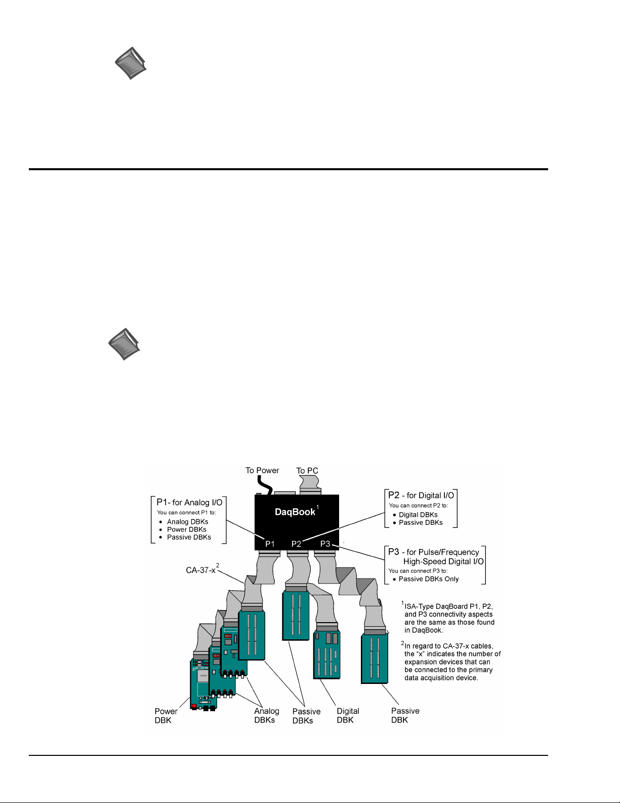
Reference Notes: During software installation, Adobe
®
PDF versions of user manuals will
automatically install onto your hard drive as a part of product support. The default location
is in the Programs directory, which can be accessed from the Windows Desktop. Refer to
the PDF documentation, especially the DBK Option Cards and Modules User’s Manual
(p/n 457-0905) for details regarding both hardware and software in relevant to DBKs.
®
A copy of the Adobe Acrobat Reader
is included on your CD. The Acrobat Reader
provides a means of reading and printing the PDF documents. Note that hardcopy versions
of the manuals can be ordered from the factory.
How Do DBKs Connect to the Data Acquisition Device?
Each DBK connects to the primary data acquisition device; e.g., a DaqBook, DaqBoard, or LogBook,
through one of three 37-pin ports, which are designated as follows:
• P1 – Analog I/O
• P2 – Digital I/O
• P3 – Pulse/Frequency/High-Speed Digital I/O
Depending on the primary data acquisition device, connectivity issues differ slightly. This will be made
clear by the figures and accompanying text that follow.
Connecting DBKs to DaqBook/100/200 Series Devices, ISA-Type DaqBoards, & LogBooks
Reference Notes:
➣
DaqBoard/2000 Series and /2000c Series users, refer to page 4.
➣
DaqBook/2000 Series users, refer to page 5.
For DaqBook/100 Series and DaqBook/200 Series devices, ISA-Type DaqBoards, and LogBooks, DBK
connections are not made directly to the port, but through a CA-37-x ribbon cable, where “x” indicates the
number of expansion devices that can be connected. For example, in addition to providing a DB37
connector to interface with the primary data acquisition device, a CA-37-3 cable includes three additional
DB37 connectors. These provide a means of adding three DBKs to one port. Use of a CA-37-16 cable will
allow up to 16 DBKs to be added. The CA-37-x cable system is excellent for DaqBooks, LogBooks, and
ISA-type DaqBoards.
/100 /200 Series
pg. 2, DBK Basics
Connecting DBKs to a DaqBook/100 Series or /200 Series Device
927196
Daq Systems
Page 91
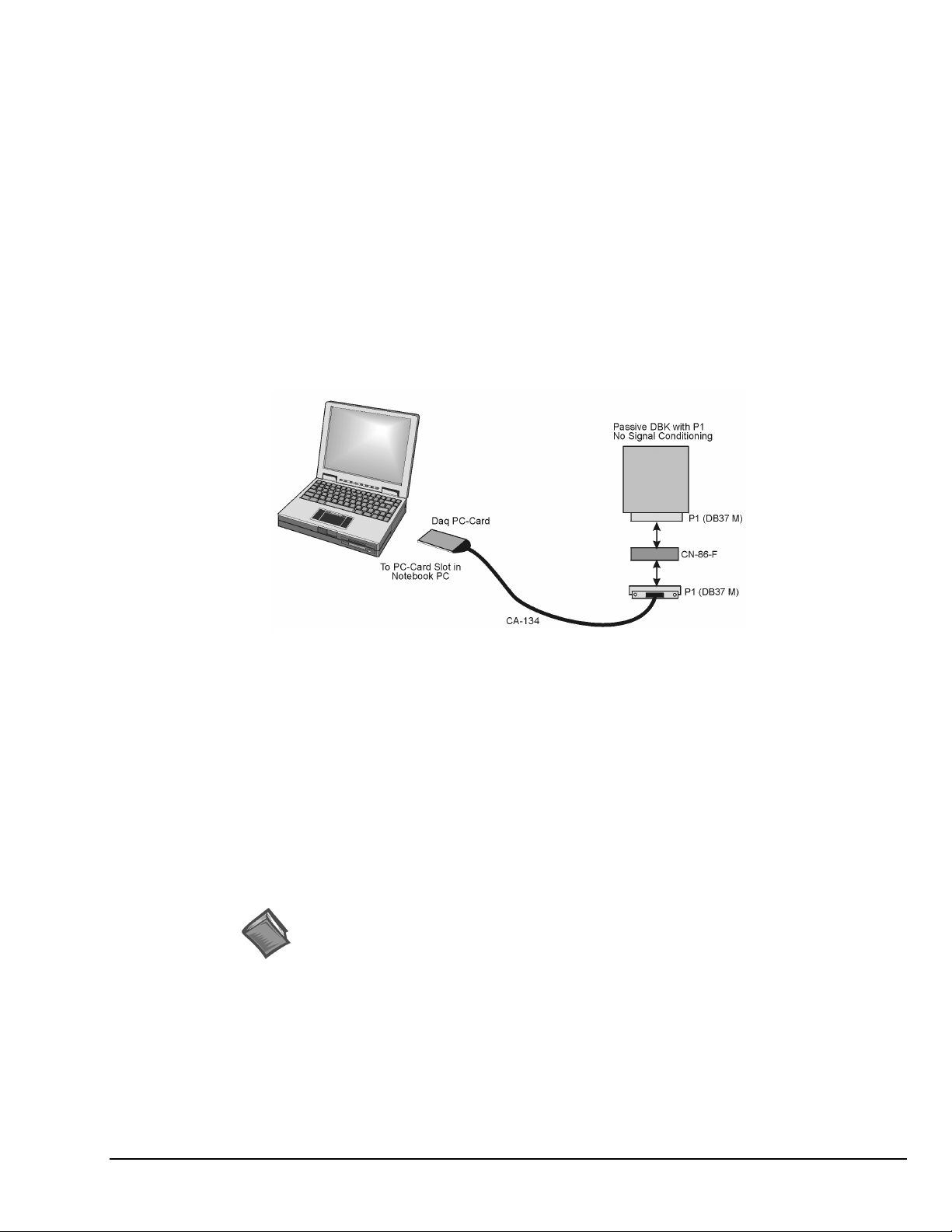
The previous figure applies to LogBooks, DaqBook/100/200 Series devices, and ISA-type DaqBoards. As
will be seen elsewhere in this document, some devices do not include all three connectors, i.e., P1, P2, and
P3.
Connecting DBKs to Daq PC-Cards
The Daq PC-Card is only intended for connections to a P1 connector of a single “passive” DBK card or
module. A passive DBK card or module is one that provides a desired connectivity (such as BNCs or screw
terminals), but performs no signal conditioning.
A CA-134 Interface Cable and a CN-86-F (dual DB37 female adapter) are used to provide the DB37,
P1 connector.
Daq PC-Card Cabling
The CA-134 cable connects to a CN-86-F adapter, which then connects to a single “passive” card or module.
The passive DBKs are:
• DBK1 – 16 Connector BNC Module
• DBK11A – Screw Terminal Option Card
• DBK40 – BNC Analog Interface
Reference Note:
For information regarding the passive DBKs (DBK1, DBK11A, and DBK40), refer to
the DBK Option Cards and Modules User’s Manual (p/n 457-0905).
Daq Systems
DBK Basics, pg. 3
927196
Page 92
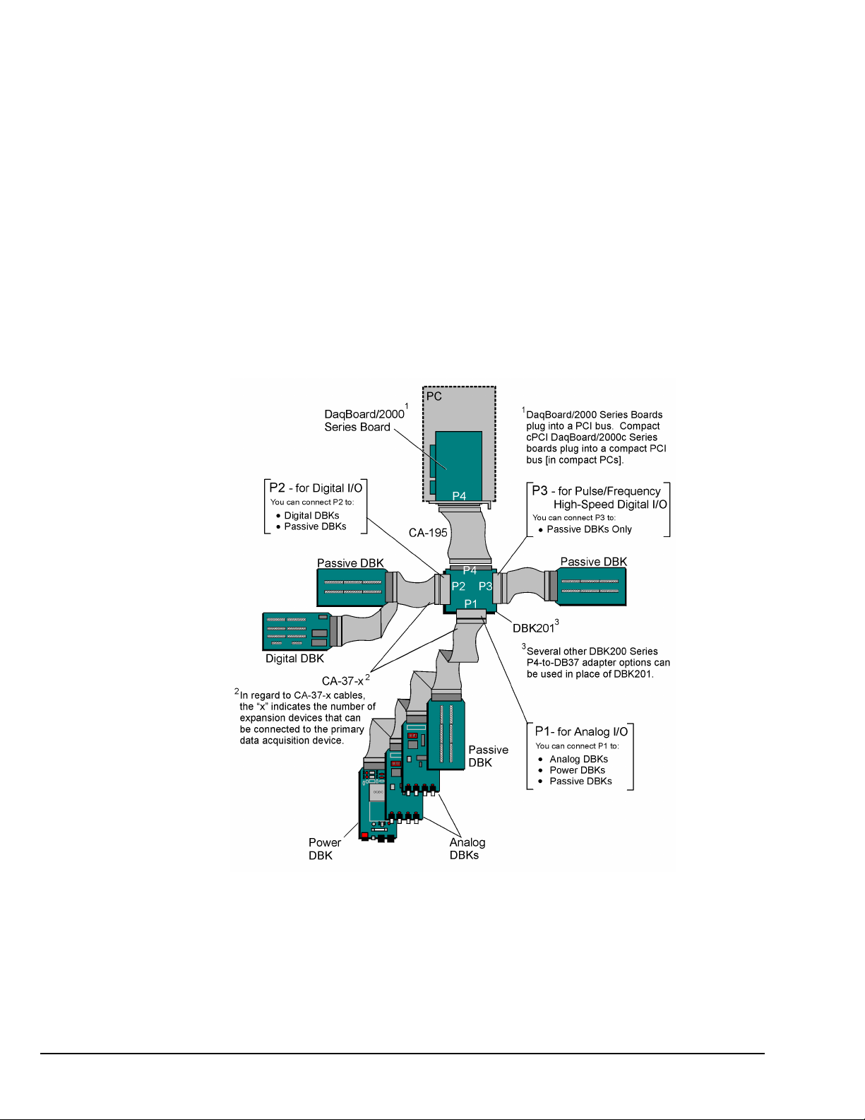
Connecting DBKs to DaqBoard/2000 Series and cPCI DaqBoard/2000c Series Boards
DaqBoard/2000 Series and cPCI DaqBoard/2000 Series boards have 100-pin connectors designated as P4.
The 100 pins correlate to various pins on P1, P2, and P3 DB37 connectors.* Connectivity in the system is as
follows (see figure).
• Both the DaqBoard/2000 and /2000c Series board connect to a CA-195 cable.
The cable has two, 100-pin, P4 connectors.
• The CA-195 connects to a DBK200 Series adapter board or adapter module for 100-pin to
37-pin adaptations, e.g., P4-to-P1, P2, P3; but not necessarily all three.*
• The DBK200 Series adapter connects to a CA-37-x ribbon cable, where “x” indicates the
number of expansion devices that can be connected. For example, in addition to providing a
DB37 connector to interface with the primary data acquisition device, a CA-37-3 cable
includes three additional DB37 connectors. These provide a means of adding three DBKs to
one port. Use of a CA-37-16 cable will allow up to 16 DBKs to be added.
• The CA-37-x cable connects to expansion DBKs, in accordance with port type. For example,
Analog DBKs to port P1, Digital DBKs to port P2, and passive DBKs to port P3.
Note: DaqBook/2000 Series Devices, which are discussed in the following section, can also connect to DBKs via
pg. 4, DBK Basics
Connecting DBKs to a DaqBoard/2000 Series Board
* DaqBoard/2003 and cPCI DaqBoard/2003c are exceptions to the above connectivity method. The /2003
board typically connects directly to a DBK205 (P4-to-Screw Terminal Adapter), as discussed in the DBK
Option Cards and Modules User’s Manual (p/n 457-0905).
a P4 connector, as indicated in the above figure.
927196
Daq Systems
Page 93
Connecting DBKs to DaqBook/2000 Series Devices
For DaqBook/2000 Series devices, DBK connections can be made to Ports P1, P2, and/or P3, as well as to
the unit’s 100-pin P4 connector. A discussion of both methods, which can be used at the same time, follows.
The P4 connector on a DaqBook/2000 Series device shares signal connections with the P1,
P2, and P3 connectors. P4 offers no additional I/O. Connecting a DBK200 Series Option
to P4 via a CA-195 cable distances the P1, P2, P3 connection from the DaqBook/2000
Series device. It does not provide any new signal I/O. See the following Caution.
CAUTION
Signal conflicts between a DaqBook/2000 Series device’s P1, P2, P3 connectors and its
P4 connector can result in erroneous readings and possible equipment damage.
Therefore, when connections have been made to P1, P2, and/or P3, use caution when
making connections through P4, and visa versa.
Refer to P1, P2, P3, and P4 pinouts to avoid making duplicate signal connections.
There are two ways to connect a DBK option to a DaqBook/2000 Series device. The first
method is preferable, as it introduces less noise.
Preferred Method – (a) Connect a CA-37-x cable to the appropriate DB37 connector
[P1, P2, or P3] on the DaqBook/2000 Series device. (b) Connect the
free end of the cable to the DBK card or module.
Optional Method – (a) Connect a CA-195-x cable to the P4 connector on the
DaqBook/2000 Series device. (b) Connect the free end of the cable
to a DBK200 Series device. (c) Connect the DBK option to the
DBK200 Series device, as applicable.
The primary reason that less noise is seen in the “preferred” method is that a
DaqBook/2000 Series device’s P1 connector pertains only to analog acquisition signals
and the P2 connector pertains only to digital I/O. This provides a strong degree of
isolation between the two signal types. However, in the case of a CA-195-x cable
connected to P4, digital and analog signals co-exist in one cable.
If you need to use the P4 connection method, use of the 8-inch ribbon cable (CA-195-1)
will result in the lowest level of crosstalk [for that method].
Daq Systems
DBK Basics, pg. 5
927196
Page 94
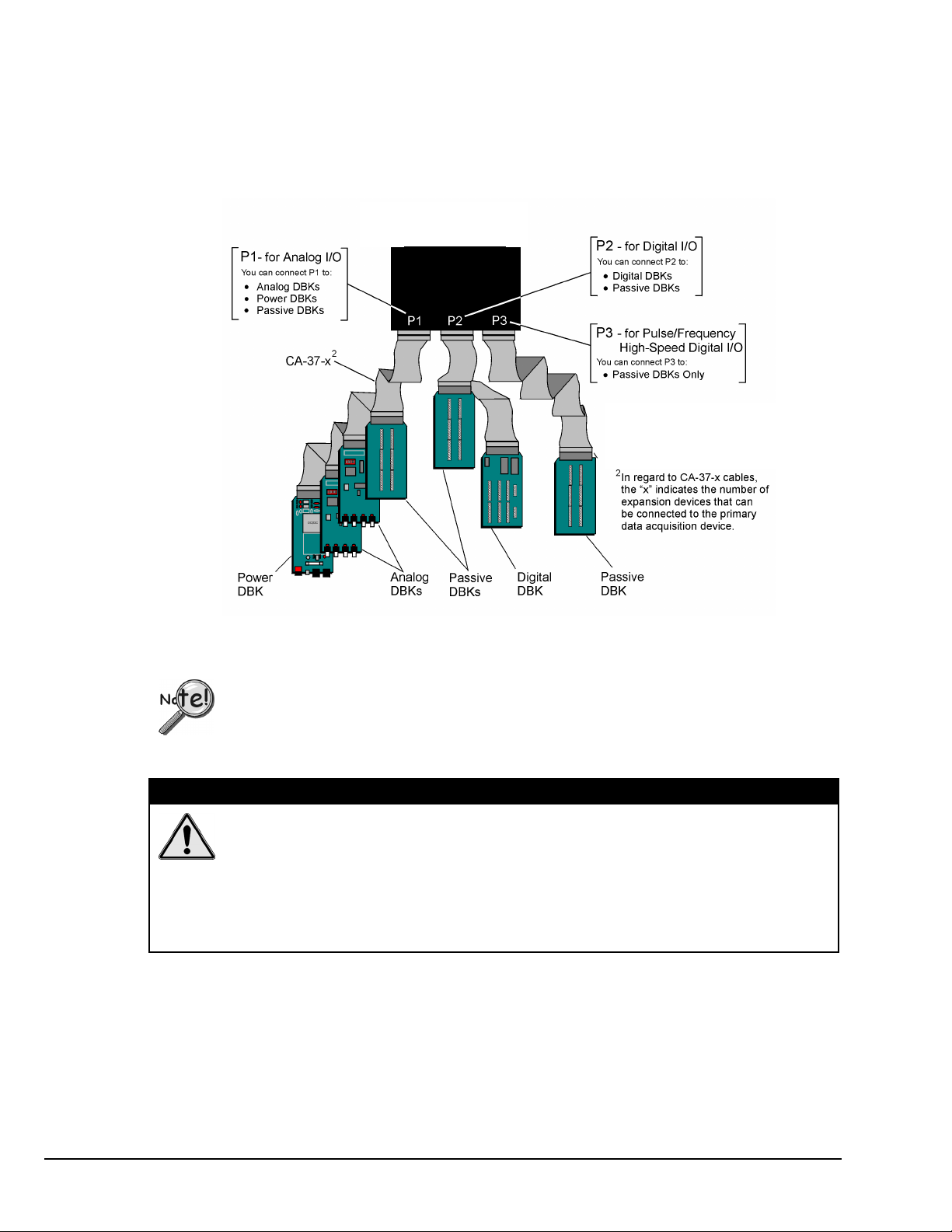
Connecting DBKs to a DaqBook/2000 Series Device via P1, P2, and/or P3
The DBKs do not connect directly to the port, but through a CA-37-x ribbon cable, where “x” indicates the
number of expansion devices that can be connected. For example, a CA-37-3 cable includes a 37-pin mating
connector to interface with the DaqBook/2000 Series DB37 connector (P1, P2, P3); it also includes three
additional DB37 connectors. These provide a means of adding three DBKs to one port. Use of a
CA-37-16 cable will allow up to 16 DBKs to be added to one DaqBook/2000 Series device DB37-type port.
DaqBook/2000
Series Device
Connecting DBKs to a DaqBook/2000 Series Device via P1, P2, and P3
The P4 connector on a DaqBook/2000 Series device shares signal connections with the P1,
P2, and P3 connectors. P4 offers no additional I/O. Connecting a DBK200 Series Option
to P4 via a CA-195 cable distances the P1, P2, P3 connection from the DaqBook/2000
Series device. It does not provide any new signal I/O. See the following Caution.
CAUTION
pg. 6, DBK Basics
Signal conflicts between a DaqBook/2000 Series device’s P1, P2, P3 connectors and its
P4 connector can result in erroneous readings and possible equipment damage.
Therefore, when connections have been made to P1, P2, and/or P3, use caution when
making connections through P4, and visa versa.
The following pinouts indicate the P1, P2, and P3 pins, and their P4 equivalents.
Use the pinouts to avoid making duplicate signal connections.
927196
Daq Systems
Page 95
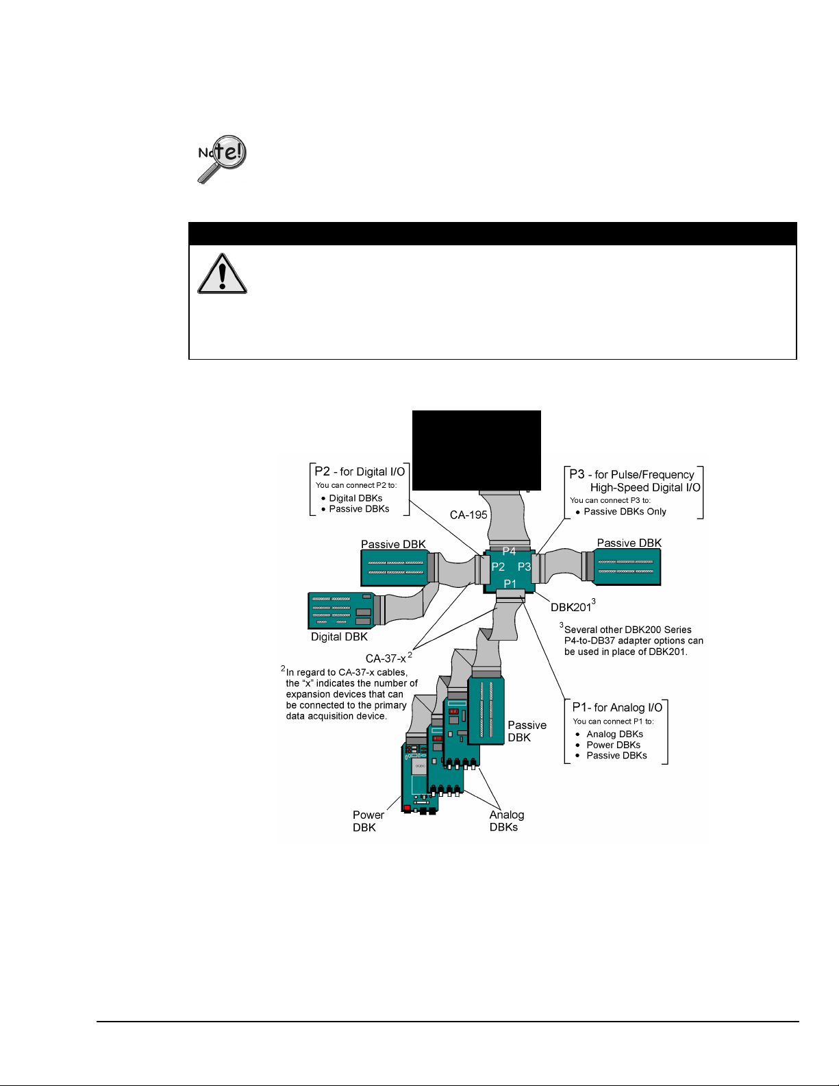
Connecting DBKs to a DaqBook/2000 Series Device via P4
Every DaqBook/2000 Series device has a 100-pin connector designated as P4. The P4 pins correlate to
various pins on P1, P2, and P3.
The P4 connector on a DaqBook/2000 Series device shares signal connections with the P1,
P2, and P3 connectors. P4 offers no additional I/O. Connecting a DBK200 Series Option
to P4 via a CA-195 cable distances the P1, P2, P3 connection from the DaqBook/2000
Series device. It does not provide any new signal I/O. See the following Caution.
CAUTION
Signal conflicts between a DaqBook/2000 Series device’s P1, P2, P3 connectors and its
P4 connector can result in erroneous readings and possible equipment damage.
Therefore, when connections have been made to P1, P2, and/or P3, use caution when
making connections through P4, and visa versa.
Refer to P1, P2, P3, and P4 pinouts to avoid making duplicate signal connections.
A brief explanation of P4 connectivity for DaqBook/2000 Series devices follows the illustration.
DaqBook/2000
Series Device
P4
Connecting DBKs to a DaqBook/2000 Series Device via P4
Daq Systems
DBK Basics, pg. 7
927196
Page 96
P4 connectivity for DaqBook/2000 Series devices is as follows:
• One end of a CA-195 cable connects to the DaqBook/2000 Series device’s 100-pin P4
connector. Note that the CA-195 cable has two P4 connectors.
• The other end of the CA-195 cable connects to a DBK200 Series adapter board [or adapter
module] for 100-pin to 37-pin adaptations, e.g., P4-to-P1, P2, P3; but not necessarily all three.
• The DBK200 Series adapter connects to one or more CA-37-x ribbon cables, where “x”
indicates the number of expansion devices that can be connected. For example, in addition to
providing a DB37 connector to interface with the primary data acquisition device, a CA-37-3
cable includes three additional DB37 connectors. These provide a means of adding three
DBKs to one port. Use of a CA-37-16 cable will allow up to 16 DBKs to be added.
• The CA-37-x cable connects to expansion DBKs, in accordance with port type. For example,
Analog DBKs to port P1, Digital DBKs to port P2, and passive DBKs to port P3.
There are two ways to connect a DBK option to a DaqBook/2000 Series device. The first
method is preferable, as it introduces less noise.
Preferred Method – (a) Connect a CA-37-x cable to the appropriate DB37 connector
[P1, P2, or P3] on the DaqBook/2000 Series device. (b) Connect the
free end of the cable to the DBK card or module.
Optional Method – (a) Connect a CA-195-x cable to the P4 connector on the
DaqBook/2000 Series device. (b) Connect the free end of the cable
to a DBK200 Series device. (c) Connect the DBK option to the
DBK200 Series device, as applicable.
The primary reason that less noise is seen in the “preferred” method is that a
DaqBook/2000 Series device’s P1 connector pertains only to analog acquisition signals
and the P2 connector pertains only to digital I/O. This provides a strong degree of
isolation between the two signal types. However, in the case of a CA-195-x cable
connected to P4, digital and analog signals co-exist in one cable.
If you need to use the P4 connection method, use of the 8-inch ribbon cable (CA-195-1)
will result in the lowest level of crosstalk [for that method].
The CE Cable Kit, p/n CA-209D, may be required for systems that require a P4 cable
length of 3 feet. The CA-209D kit includes a shielded version of the CA-195 cable, two
grounding pigtails, and associated cable clamps. When properly connected, the shielded
cable provides greater immunity to noise. The CE Compliance chapter includes details.
pg. 8, DBK Basics
927196
Daq Systems
Page 97
DBK Identification Tables
Analog Output DBKs
Analog Output
Product
DBK2 Voltage Output Card 4 channels P1
DBK5 Current Output Card 4 channels P1
DBK46 Analog Output Card; factory install option for
Digital I/O Control DBKs
Digital I/O / Control
Product
DBK20 General-Purpose Digital I/O Card (Screw Terminals) 48 channels P2
DBK21 General-Purpose Digital I/O Card (DB37 Connectors) 48 channels P2
DBK23 Optically Isolated Digital-Input Module 24 channels P2
DBK24 Optically Isolated Digital-Output Module 24 channels P2
DBK25 Relay Output Card 8 channels P2
DBK208 Carrier board for Opto-22 Compatible SSR Digital Modules. 16 Channels P2 or P4
DBK210 Carrier Board for Grayhill 70M-Series Mini-Modules 32 Channels P2 or P4, P1 exp.
Analog Signal Conditioning DBKs
The DBKs that are used for analog signal conditioning attach to transducers and condition their outputs into
analog voltages. An A/D converter, located in the primary acquisition device, measures the analog
voltages. There are many signal-conditioning solutions available (and more are in development). Note that
DBK high-capacity modules require more circuitry than can fit on a compact card.
Name/Description
DaqBook/2000 Series Devices and WBK41 Modules
Name/Description
4 channels Internal
I/O
I/O
Connects To:
PC Board
Connects To:
Analog Signal Conditioning
Product
DBK4 Dynamic Signal Input Card 2 channels P1
DBK7 Frequency-to-Voltage Input Card 4 channels P1
DBK8 High-Voltage Input Card 8 channels P1
DBK9 RTD Measurement Card 8 channels P1
DBK12 Low-Gain Analog Multiplexing Card
DBK13 High-Gain Analog Multiplexing Card
DBK15 Universal Current/Voltage Input Card Note 2 16 channels P1
DBK16 Strain-Gage Measurement Card 2 channels P1
DBK17 Simultaneous Sample & Hold Card 4 channels P1
DBK18 Low-Pass Filter Card 4 channels P1
DBK19 Thermocouple Card
DBK42 5B Isolated Signal-Conditioning Module 16 channels P1
DBK43A Strain-Gage Measurement Module 8 channels P1
DBK44 5B Isolated Signal-Conditioning Card 2 channels P1
DBK45 SSH and Low-Pass Filter Card 4 channels P1
DBK50 Isolated High-Voltage Input Module 8 channels P1
DBK51 Isolated Low-Voltage Input Module 8 channels P1
DBK52 Thermocouple Input Module
DBK53 Low-Gain Analog Multiplexing Module
DBK54 High-Gain Analog Multiplexing Module
DBK70 Vehicle Network Interface, Analog Multiplexer Module 16 channels P1
DBK80 Differential Voltage Input Card with Excitation Output 16 channels P1
DBK81 Thermocouple Card, High-Accuracy 7 channels P1
DBK82 Thermocouple Card, High-Accuracy 14 channels P1
DBK83 Thermal Couple Card, High-Accuracy; uses Connection Pod 14 channels P1
DBK84 Thermocouple Module, High-Accuracy 14 channels P1
DBK90 Thermocouple Module, High-Accuracy 56 channels P1
DBK207 Carrier Board for 5B Compatible Analog Input Modules 16 channels P1 or P4
DBK207/CJC Carrier Board for 5B Compatible Analog Input Modules.
Note 1
Note 2
Name/Description
DBK207/CJC includes cold junction compensation (CJC)
P1, P2, and P3 DB37 connectors do not exist on the DaqBoard/2000 Series or /2000c Series boards, but
:
are obtained by using P4 adapters (DBK200 series boards).
For DaqBoard/2000 and cPCI DaqBoard/2000 Series boards, internal clocks should be set to 100 kHz
:
when used with any of the following DBK options: DBK12, DBK13, DBK15, DBK19, DBK52, DBK53, and
DBK54. See specific DBK section for details.
16 channels P1
Note 2
16 channels P1
Note 2
14 channels P1
Note 2
14 channels P1
Note 2
16 channels P1
Note 2
16 channels P1
Note 2
16 channels P1 or P4
I/O
Connects To:
Daq Systems
DBK Basics, pg. 9
927196
Page 98
Expansion and Terminal Panel Connection DBKs
The following DBKs offer provide various expansion and connection options. The stackable 3-slot DBK10
low-profile enclosure can be used for up to three DBKs. If a system has more than 3 DBKs, the 10-slot
DBK41 can be used. Several DBK41s can be daisy-chained to accommodate many DBKs in one system.
Expansion and Connection, General
Product
DBK1 16-Connector BNC Adapter Module 16 connectors P1
DBK10 3-Slot Expansion Chassis 3 cards P1, P2, or P3
DBK11A Screw-Terminal Option Card (DB37-Screw Terminal Block) Component
DBK40 BNC Interface 18 connectors P1
DBK41 Analog Expansion Enclosure 10 cards P1
DBK60 Expansion Chassis with Termination Panels 3 cards P1 or P2
Name/Description
Termination Panels, Connectivity for DaqBoard/260
Product
DBK601 Termination Panel - Blank rear panel none N/A
DBK602 Termination Panel - BNC rear panel 16 connectors DBK Card
DBK603 Termination Panel - Safety Jacks, single ended 16 connectors DBK Card
DBK604 Termination Panel - Safety Jacks, differential 8 differential (16) DBK Card
DBK605 Termination Panels - Thermocouple, differential panels;
DBK606 Termination Panel – 3 Terminal Blocks; 16 connections per TB 48 connectors DBK Card
DBK607 Termination Panel – strain relief clamp none N/A
DBK608 Termination Panel – 3 female DB37 connectors three DB37 DBK Card
Name/Description
specify type: B, J, K, R, S, or T
Several signal connection options were developed primarily for use with DaqBoard/2000 Series and
cPCI DaqBoard/2000c Series Boards. The DBK200 Series P4-Adapter documentation provides the basic
connection concepts. That information, along with the related DBK subsections should enable you to set up
your desired configuration.
P4 Adaptive Connection for DaqBoard/2000 Series and cPCI DaqBoard/2000c Series
Product
DBK200 P4-to-P1 Adapter Board P1 P4
DBK201 P4-to-P1/P2/P3 Adapter Board P1, P2, P3 P4
DBK202 P4-to-P1/P2/P3 Adapter Board with Screw-Terminals P1, P2, P3 P4
DBK203 A module version of DBK202 P1, P2, P3 P4
DBK204 A module version of DBK202 with an included CE cable kit. P1, P2, P3 P4
DBK205 P4-to-TB1 12-slot Screw Terminal Block for DaqBoard/2003. TB1, 12-slot P4
DBK206 P4-to-P1/P2/P3 Adapter Board with Screw-Terminals P1, P2, P3 P4
DBK209 P4-to-P1/P2/P3 Mini-Adapter Board P1, P2, P3 P4
Note 1
Name/Description
P1, P2, and P3 DB37 connectors do not exist on the DaqBoard/2000 Series, or /2000c Series boards,
:
but are obtained by using P4 adapters (DBK200 series). These adapters typically connect to the
DaqBoard/2000 Series [/2000c Series] 100-pin P4 connector via cable.
I/O
sockets
I/O
16 differential DBK Card
I/O
Connects To:
P1, P2, or P3
Connects To:
Connects To:
Power Supply DBKs
Power supply type DBKs are typically used in laboratory, automotive, and field applications. Input power
can come from any +10 to +20 VDC source, or from an AC source by using an appropriately rated AC-toDC adapter. The DBK30A rechargeable power supply can power DBK modules where AC mains are not
available (the DBK30A outputs 28 V for powering transducers). For a large number of DBK cards, the
DBK32A or DBK33 can be installed into an expansion slot. The DBK33 is used when +5 V is required in
addition to ±15 VDC. The DBK34 provides a steady 12 or 24 VDC while working with vehicle electrical
systems that may be turned on or off during testing.
Power Supply
Product
DBK30A Rechargeable Battery/Excitation Module +12-14, 24-28 VDC (3.4 A-hr @ 14 VDC)
DBK32A Auxiliary Power Supply Card ±15 V @ 500 mA
DBK33 Triple-Output Power Supply Card ±15 V @ 250 mA; +5 V @ 1 A
DBK34 Vehicle UPS Module 12/24 VDC (5 A-hr @12 VDC)
DBK34A UPS Battery Module 12/24 VDC (5 A-hr @12 VDC)
pg. 10, DBK Basics
Name/Description
927196
Power
Daq Systems
Page 99

Tips on Setting up a Data Acquisition System
A successful installation involves setting up equipment and setting software parameters. In addition to this
manual, you may need to consult your Daq device or LogBook user’s manual.
DBKs should be configured before connections are made and power is applied. This sequence can prevent
equipment damage and will help ensure proper operation on startup. Many DBKs have on-board jumpers
and/or DIP switches that are used for setting channels and other variables. You will need to refer to the
individual DBK document modules to ensure that the DBKs are properly configured for you application.
Prior to designing or setting up a custom data acquisition system, you should review the following tips.
After reviewing the material you can write out the steps to setup a system that will best meet your specific
application needs.
1. The end use of the acquisition data should be used to determine how you set up and program your
acquisition system. Prior to creating the system you should understand its layout and know how you are
going to assign the channels. If you can answer the following questions you are off to a good start. If
not, you need to find the answers.
• What engineering units, ranges, sampling rates, etc. are best for your data?
• Will the data be charted graphically, statistically processed, or exported to other programs?
• How will the data be used?
• How will the data be saved?
• What are your system’ power requirements? Using several DBKs or transducers that require
excitation current may require an extra power supply, e.g., a DBK32A.
2. Assign channel numbers.
3. Plan the location of transducers, cable runs, DBKs, the acquisition device [LogBook or Daq device],
and the computer. Label your transducers, cables, and connectors to prevent later confusion.
4. When configuring your LogBook or Daq device(s) consider the following:
• LogBook calibration is typically performed automatically through LogView software;
however, some DBKs may require manual calibration.
• The DaqBook/100 Series and DaqBook/200 Series devices, and DaqBoards (ISA type)
have internal jumpers and switches that you must set manually to match your
application.
• Some DaqBook/100 Series and DaqBook/200 Series models are partially configured in
software.
• DaqBook/2000 Series devices have no jumpers or internal switches and are configured
entirely through software.
• Daq PC-Cards are configured entirely in software.
• DaqBoard/2000 Series boards are PCI type boards. They have no jumpers or switches and
are configured entirely through software.
• cPCI DaqBoard/2000c Series boards are compact PCI (cPCI) type boards. They have no
jumpers or switches and are configured entirely through software.
• You may need to refer to other documentation, such as Quick Starts, Installation Guides,
User’s Manuals, and pertinent DBK document modules.
5. Perform all hardware configurations before connecting signal and power. Remember to configure all
the DBK cards and modules for your application. Several jumpers and DIP switches may need to be set
(channel, gain, filters, signal mode, etc).
Daq Systems
6. Setting up channel parameters often requires both hardware and software setup.
7. Route and connect all signal and power cables while all power is turned OFF.
8. To minimize electrical noise, route all signal lines away from any RF or high-voltage devices.
DBK Basics, pg. 11
927196
Page 100

9. Follow your device’s specific installation instructions. For certain devices software should be installed
first; for others, hardware should be installed prior to software installation.
10. After software is loaded, remember to set the software parameters as needed for your application.
The software must recognize all the hardware in the system. Measurement units and ranges
should be checked to verify that they meet your application requirements.
11. Remember to set all channels to the proper mode for your DBK or other signal source.
12. After your system is up and running, verify proper data acquisition and data storage.
13. Verify system accuracy; adjust ranges or calibrate as needed.
14. Device specific information regarding system setup and expansion can be found in the Daq and
LogBook User’s manuals; and in the applicable DBK document modules of this manual.
15. If you are considering system expansion, review the DBK10, DBK41, and DBK60 document modules.
The best option depends on the number of DBK cards in your system. For just a few cards, use the
stackable 3-slot DBK10 low-profile expansion enclosure. For more than six cards, use the 10-slot
DBK41. DBK41s can be daisy-chained to one-another to handle a large number of DBKs.
16. In regard to power management, you should review the DBK30A, DBK32A, and DBK33 document
modules. For portable applications, the compact DBK30A rechargeable power supply can provide
power to the DBK10 or DBK41. The DBK30A also includes a 28 V output for powering 4 to 20 mA
transducers. For applications with many DBK cards (initially or in future expansion), the DBK32A or
DBK33 can be installed into any expansion slot. The DBK32A provides ±15 VDC and the DBK33
provides ±15 VDC and +5 VDC.
Power Supplies and Power Connectors
Power supplies convert the raw power they receive into a lower DC voltage and/or current for use by
devices with various power demands. Many of the power supplies that are used to power data acquisition
equipment are of the switching-mode type. These devices provide a regulated output whether the power
supply’s input is, for example, 60 Hz, 120 VAC as in the United States or, 50 Hz, 220 VAC as found in
European countries. Small power supplies, that do not switch, consist of simple transformer/rectifiers and
filtered capacitors; and operate over a smaller voltage range.
DaqBook/2000 Series Devices – The switching-mode power supply [commonly used with DaqBook/2000
Series systems] has an input range of 100 VAC to 240 VAC at 50 Hz to 60 Hz. The power supply’s output
[to the DaqBook/2000 Series device] is 15 VDC @ 2.7 amps via a DIN5 connector.
LogBooks - The switching-mode power supply [commonly used with LogBook systems] has an input
range of 100 VAC to 240 VAC at 50 Hz to 60 Hz. The power supply’s output [to the LogBook] is 15
VDC @ 2.7 amps via a DIN5 connector.
DaqBook/100 and DaqBook/200 Series Devices - Power supplies that are used with DaqBook/100 Series
and DaqBook/200 Series devices are typically of the transformer/rectifier type. They supply the unit with
15 VDC @ 900 mA via a DIN5 connector.
pg. 12, DBK Basics
927196
Daq Systems
 Loading...