

Page 1
Page 2
Page 3

Table of Contents
Preface
About this User's Guide ....................................................................................................................... 5
What you will learn from this user's guide ......................................................................................................... 5
Conventions used in this user's guide ................................................................................................................. 5
Where to find more information ......................................................................................................................... 5
Chapter 1
Introducing the OMB-DAQ-2416 .......................................................................................................... 6
Overview: OMB-DAQ-2416 features ................................................................................................................ 6
Software features ................................................................................................................................................ 6
Chapter 2
Installing the OMB-DAQ-2416 .............................................................................................................. 7
What comes with your OMB-DAQ-2416 shipment? ......................................................................................... 7
Hardware .......................................................................................................................................................................... 7
Optional components ........................................................................................................................................................ 8
Additional documentation ................................................................................................ ................................................. 8
Unpacking the OMB-DAQ-2416 ....................................................................................................................... 8
Installing the software ........................................................................................................................................ 8
Installing the hardware ....................................................................................................................................... 8
Connecting to an OMB-AI-EXP32 with the DSUB37 expansion connector ..................................................... 9
Configuring the hardware ................................................................................................................................... 9
Connecting the board for I/O operations .......................................................................................................... 10
Connectors, cables – main I/O connector .........................................................................................................................10
Screw terminal pin out – differential ...............................................................................................................................11
Screw terminal pin out – single-ended .............................................................................................................................12
Chapter 3
Functional Details ............................................................................................................................... 13
OMB-DAQ-2416 components .......................................................................................................................... 13
LEDs ................................................................................................................................................................................14
USB connector .................................................................................................................................................................14
External power connector ................................................................................................................................................14
Screw terminal wiring ...................................................................................................................................... 14
Mechanical drawings ........................................................................................................................................ 15
Block diagram .................................................................................................................................................. 16
Analog/TC input terminals ............................................................................................................................... 17
Analog input mode ...........................................................................................................................................................17
Thermocouple inputs .......................................................................................................................................................17
Noise filtering, data rate, and throughput rate ..................................................................................................................18
Multiple-channel throughput rates ...................................................................................................................................19
Input isolation ................................................................................................................................................... 20
Digital I/O ......................................................................................................................................................... 21
Internal pull-up/pull-down capability ..............................................................................................................................21
External pull-up/pull-down capability .............................................................................................................................22
Counter input terminals (CTR0, CTR1) ........................................................................................................... 23
3
Page 4

OMB-DAQ-2416 User's Guide
Chapter 4
Calibrating the OMB-DAQ-2416 ......................................................................................................... 24
Calibration methods .......................................................................................................................................... 24
Factory calibration ................................................................................................ ...........................................................24
Self calibration .................................................................................................................................................................24
Chapter 5
Specifications ...................................................................................................................................... 25
Analog input ..................................................................................................................................................... 25
Channel configurations ..................................................................................................................................... 26
Compatible sensors ..........................................................................................................................................................26
Accuracy ........................................................................................................................................................... 26
Thermocouple measurement accuracy .............................................................................................................................26
Analog input DC voltage measurement accuracy: ...........................................................................................................35
Input bandwidth ...............................................................................................................................................................37
Noise performance ...........................................................................................................................................................37
Channel switching error ...................................................................................................................................................38
Throughput rate ................................................................................................................................................ 39
Analog input calibration ................................................................................................................................... 40
Digital input/output........................................................................................................................................... 40
Counter ............................................................................................................................................................. 41
Memory ............................................................................................................................................................ 41
Microcontroller ................................................................................................................................................. 41
Power ................................................................................................................................ ................................ 42
USB specifications ........................................................................................................................................... 42
Environmental .................................................................................................................................................. 42
Mechanical ....................................................................................................................................................... 43
Screw terminal connector type and pin-out ...................................................................................................... 43
Screw terminal pin out .....................................................................................................................................................43
Optional OMB-AI-EXP32 expansion module .................................................................................................. 46
OMB-AI-EXP32 screw terminal pin out .........................................................................................................................48
OMB-DAQ-2416 screw terminal pin out (with OMB-AI-EXP32 attached) ....................................................................50
4
Page 5
Preface
About this User's Guide
What you will learn from this user's guide
This user's guide explains how to install, configure, and use the OMB-DAQ-2416 so that you get the most out
of its analog input, thermocouple (TC) input, digital I/O, and counter/timer I/O features.
This user's guide also refers you to related documents available on our web site, and to technical support
resources.
Conventions used in this user's guide
For more information on …
Text presented in a box signifies additional information and helpful hints related to the subject matter you are
reading.
Caution! Shaded caution statements present information to help you avoid injuring yourself and others,
damaging your hardware, or losing your data.
< : > Angle brackets that enclose numbers separated by a colon signify a range of numbers, such as those assigned
to registers, bit settings, etc.
bold text Bold text is used for the names of objects on the screen, such as buttons, text boxes, and check boxes. For
example:
1. Insert the disk or CD and click the OK button.
italic text Italic text is used for the names of manuals and help topic titles, and to emphasize a word or phrase. For
example:
The InstaCal installation procedure is explained in the OMB-DAQ-2416 Series Software User’s Guide.
Never touch the exposed pins or circuit connections on the board.
Where to find more information
For additional information relevant to the operation of your hardware, refer to the Documents subdirectory
where you installed the software, or search for your device on our website at www.omega.com.
5
Page 6

Chapter 1
Introducing the OMB-DAQ-2416
Overview: OMB-DAQ-2416 features
The OMB-DAQ-2416 is supported under popular Microsoft® Windows® operating systems. The OMB-DAQ2416 is a multifunction measurement and control board designed for the USB bus.
The OMB-DAQ-2416 is a full-speed, multiplexed 24-bit measurement system that provides up to 16 differential
and up to 32 single-ended (SE) analog inputs. It offers software-selectable analog input ranges of ±20 V, ±10 V,
±5 V, ±2.5 V, ±1.25 V, ±0.625 V, ±0.312 V, ±0.156 V, and ±0.078 V.
It also protects your computer by providing a minimum of 500 VDC input isolation between field wiring and
the USB interface.
You can configure up to 16 of the analog inputs as differential thermocouple (TC) inputs. In thermocouple
mode, the OMB-DAQ-2416 includes built-in cold-junction compensation and open thermocouple detection.
You can add up to 32 single-ended or up to 16 differential channels by connecting the OMB-DAQ-2416 to an
OMB-AI-EXP32 expansion module. Each channel is software-configurable as single-ended or differential. You
lose one SE channel for each channel pair configured differentially.
The device has eight high-speed lines of digital I/O and two 32-bit counters. You can expand up to 24 DIO
channels by connecting the OMB-DAQ-2416 to an OMB-AI-EXP32 expansion module.
Six banks of removable screw-terminal blocks provide connectivity to the analog input channels, digital I/O
lines, and counter/timer channels.
Software features
For information on the features of InstaCal and the other software included with your OMB-DAQ-2416, refer to
the OMB-DAQ-2416 Series Software User’s Guide that shipped with your device.
6
Page 7
Installing the OMB-DAQ-2416
What comes with your OMB-DAQ-2416 shipment?
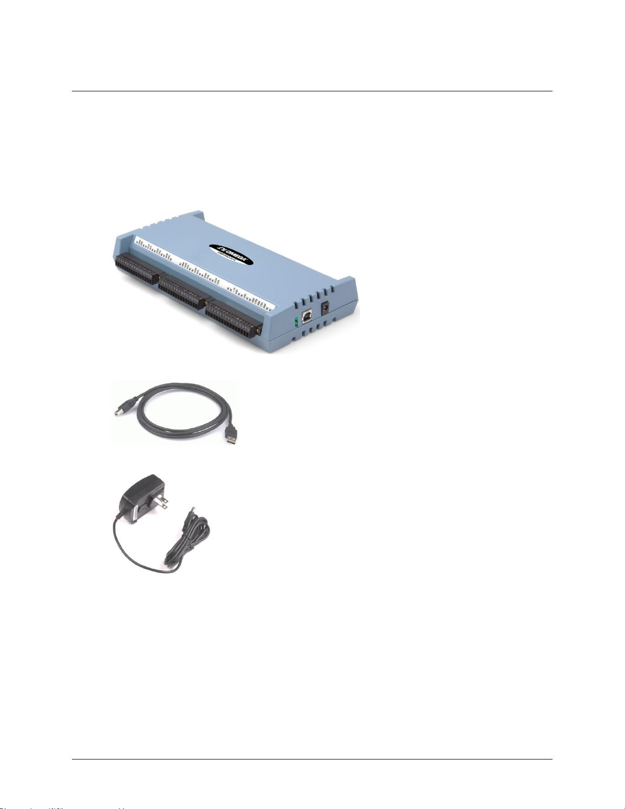
As you unpack your OMB-DAQ-2416, verify that the following components are included.
Hardware
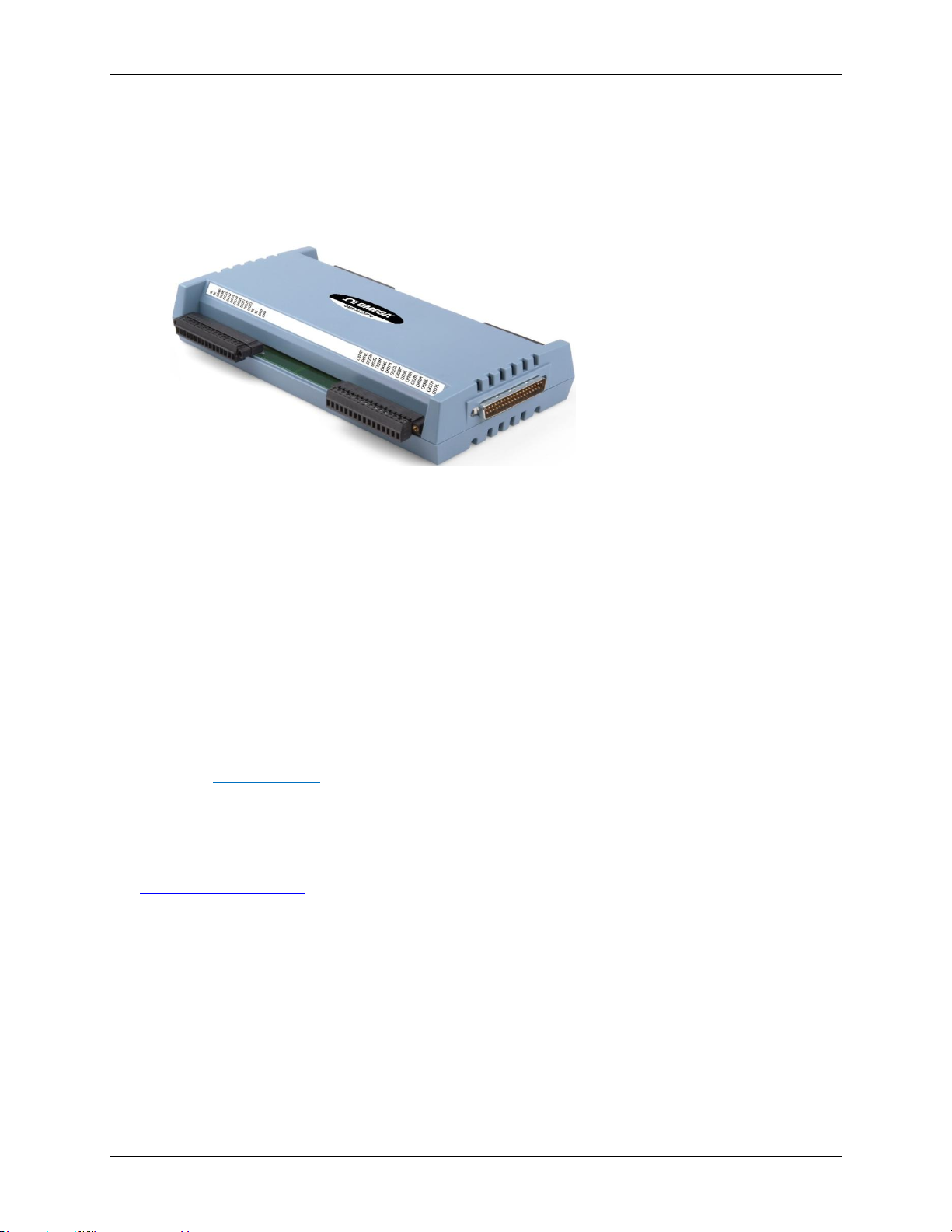
OMB-DAQ-2416
Chapter 2
USB cable (2-meter length)
OMB-DAQ-2416-ADAP (+5VDC, 10 Watt regulated power supply)
7
Page 8
OMB-DAQ-2416 User's Guide Installing the OMB-DAQ-2416
Optional components
Expansion devices that are compatible with the OMB-DAQ-2416 must be ordered separately. If you ordered the
following product with your device, it should be included with your shipment.
OMB-AI-EXP32
Analog input expansion module adds up to 16 differential or 32 single-ended inputs to the OMB-DAQ-2416.
Additional documentation
In addition to this hardware user's guide, you should also receive the OMB-DAQ-2416 Series Software User’s
Guide. This booklet supplies a brief description of the software you received with your OMB-DAQ-2416 and
information regarding installation of that software. Please read this booklet completely before installing any
software or hardware.
Unpacking the OMB-DAQ-2416
As with any electronic device, you should take care while handling to avoid damage from static
electricity. Before removing the OMB-DAQ-2416 from its packaging, ground yourself using a wrist strap or by
simply touching the computer chassis or other grounded object to eliminate any stored static charge.
If any components are missing or damaged, notify Omega Engineering immediately by phone, fax, or e-mail.
Installing the software
Refer to the OMB-DAQ-2416 Series Software User’s Guide for instructions on installing the software on the
OMB-DAQ-2416 Series Data Acquisition Software CD. This booklet is available in PDF at
www.omega.com/manuals.
We recommend that you download the latest Windows Update onto your computer before installing and
operating the OMB-DAQ-2416.
Installing the hardware
1. Connect the OMB-DAQ-2416-ADAP power supply to the device's external power connector, and plug the
other end into a power outlet.
2. Connect the USB cable to the device's USB connector and to a USB port on your computer. A USB2.0 port
is recommended.
When you connect the OMB-DAQ-2416 for the first time, a Found New Hardware message opens as the
OMB-DAQ-2416 is detected. When the message closes, the installation is complete.
8
Page 9
OMB-DAQ-2416 User's Guide Installing the OMB-DAQ-2416
The Power LED (bottom LED) blinks during device detection and initialization, and then remains solid if
properly detected. If not, check if the OMB-DAQ-2416 has sufficient power. When the device is first powered
on, there is usually a momentary delay before the Power LED begins to blink, or come on solid.
Caution! Do not disconnect any device from the USB bus while the computer is communicating with the
OMB-DAQ-2416, or you may lose data and/or your ability to communicate with the OMB-DAQ-
2416.
Connecting to an OMB-AI-EXP32 with the DSUB37 expansion connector
Use the 37-pin expansion connector to connect the OMB-DAQ-2416 to an OMB-AI-EXP32 expansion module.
To connect the two devices directly to each other, follow these steps.
1. Disconnect the USB cable from the OMB-DAQ-2416.
2. Remove the external power cable from the OMB-DAQ-2416.
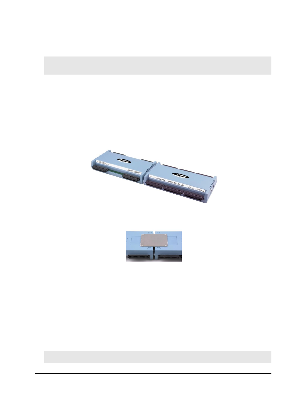
3. Connect the two devices together by inserting the OMB-AI-EXP32's DSUB37 connector into the DSUB37
connector on the OMB-DAQ-2416.
Figure 1. OMB-DAQ-2416 directly connected to an OMB-AI-EXP32
4. Turn the connected modules over and secure the connection by screwing the connection plate to both
modules, as shown below.
Figure 2. OMB-DAQ-2416 secured to an OMB-AI-EXP32
5. Connect the external power supply to the OMB-DAQ-2416's external power connector, and plug the other
end into an AC outlet.
6. Connect the USB cable from the OMB-DAQ-2416 to the host computer's USB port.
Connect to a USB 2.0 high speed hub to achieve the highest transfer rate (480 Mbps). When connected to a
USB 1.1 full-speed port, the transfer rate is limited to 12 Mbps.
Configuring the hardware
Except for the DIO pull-up selection, all hardware configuration options on the OMB-DAQ-2416 are software
controlled. You can select some of the configuration options using InstaCal, such as the analog input
configuration (single-ended or differential channels). When measuring from thermocouples, make sure you
configure the channels for differential mode.
Caution! Turn off power to all devices connected to the system before making connections. Electrical shock
or damage to equipment can result even under low-voltage conditions.
9
Page 10
OMB-DAQ-2416 User's Guide Installing the OMB-DAQ-2416
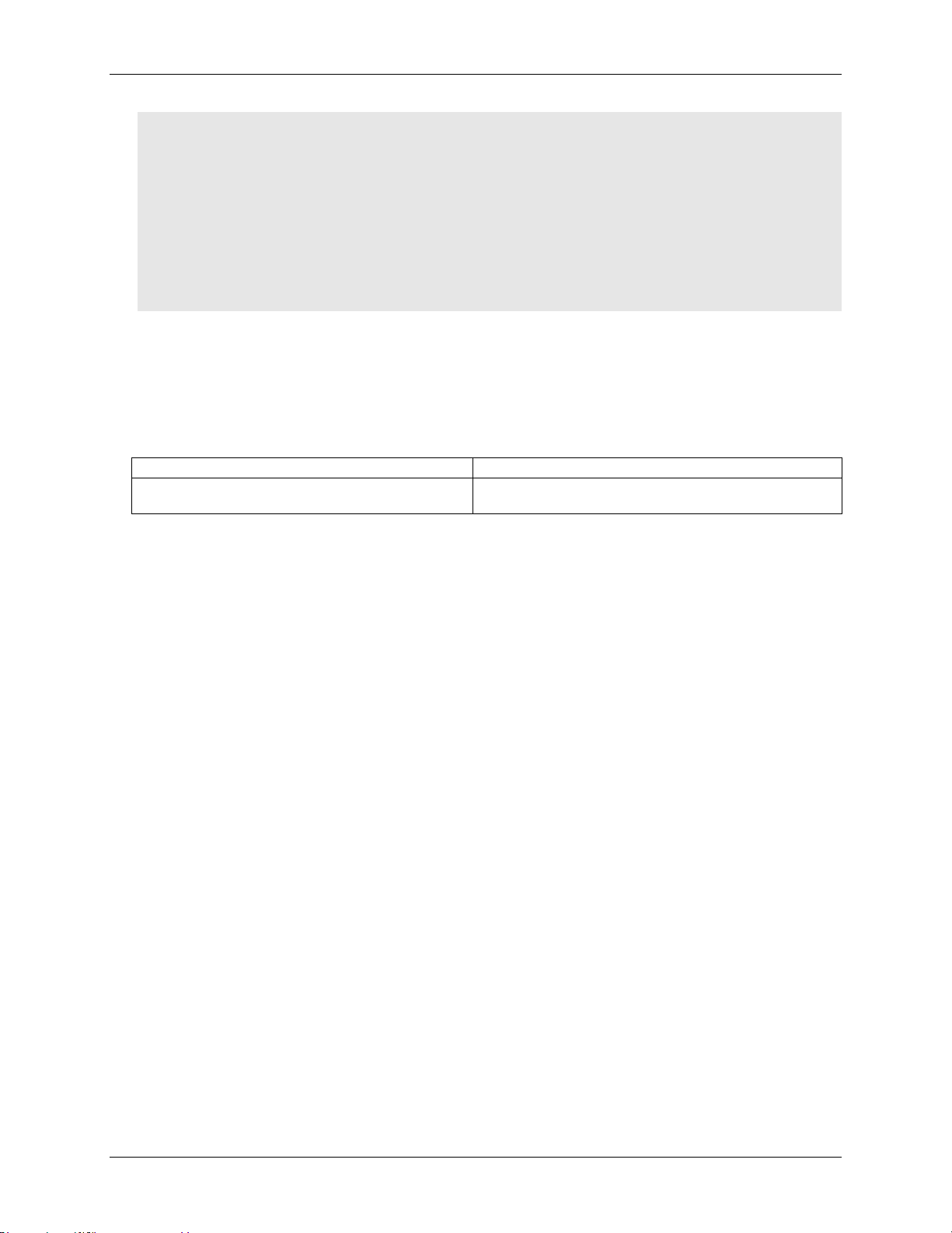
Main connectors
Six banks of detachable screw terminals
Compatible accessory product for the 37-pin expansion
connector
OMB-AI-EXP32 expansion board with screw terminals
(connects directly to the OMB-DAQ-2416)
Caution! Always handle components carefully, and never touch connector terminals or circuit components
unless you are following ESD guidelines in an appropriate ESD-controlled area. These guidelines
include using properly grounded mats and wrist straps, ESD bags and cartons, and related
procedures.
Avoid touching board surfaces and onboard components. Only handle boards by their edges. Make
sure the OMB-DAQ-2416 does not come into contact with foreign elements such as oils, water,
and industrial particulate.
The discharge of static electricity can damage some electronic components. Semiconductor
devices are especially susceptible to ESD damage.
Connecting the board for I/O operations
Connectors, cables – main I/O connector
The following table lists the board connectors and compatible accessory products for the OMB-DAQ-2416.
Main connector specifications
10
Page 11
OMB-DAQ-2416 User's Guide Installing the OMB-DAQ-2416
49 NC No connection
50 CH15L Channel 15 LO
51 CH15H Channel 15 HI
52 NC No connection
53 NC No connection
54 CH14L Channel 14 LO
55 CH14H Channel 14 HI
56 NC No connection
57 NC No connection
58 CH13L Channel 13 LO
69 CH13H Channel 13 HI
60 NC No connection
61 NC No connection
62 CH12L Channel 12 LO
63 CH12H Channel 12 HI
64 NC No connection
No connection NC 1
Channel 0 HI CH0H 2
Channel 0 LO CH0L 3
No connection NC 4
No connection NC 5
Channel 1 HI CH1H 6
Channel 1 LO CH1L 7
No connection NC 8
No connection NC 9
Channel 2 HI CH2H 10
Channel 2 LO CH2L 11
No connection NC 12
No connection NC 13
Channel 3 HI CH3H 14
Channel 3 LO CH3L 15
No connection NC 16
No connection NC 17
Analog ground GND 18
Channel 4 HI CH4H 19
Channel 4 LO CH4L 20
No connection NC 21
No connection NC 22
Channel 5 HI CH5H 23
Channel 5 LO CH5L 24
No connection NC 25
No connection NC 26
Channel 6 HI CH6H 27
Channel 6 LO CH6L 28
No connection NC 29
No connection NC 30
Channel 7 HI CH7H 31
Channel 7 LO CH7L 32
No connection NC 33
No connection NC 34
+5 V output +5V 35
Analog ground GND 36
No connection NC 37
No connection NC 38
Analog ground GND 39
No connection NC 40
No connection NC 41
Analog ground GND 42
Counter input 0 CTR0 43
Analog ground GND 44
Counter input 1 CTR1 45
Analog ground GND 46
No connection NC 47
No connection NC 48
65 NC No connection
66 GND Analog ground
67 CH11L Channel 11 LO
68 CH11H Channel 11 HI
69 NC No connection
70 NC No connection
71 CH10L Channel 10 LO
72 CH10H Channel 10 HI
73 NC No connection
74 NC No connection
75 CH9L Channel 9 LO
76 CH9H Channel 9 HI
77 NC No connection
78 NC No connection
79 CH8L Channel 8 LO
80 CH8H Channel 8 HI
81 GND Analog ground
82 NC No connection
83 NC No connection
84 GND Analog ground
85 DIO7 Digital input/output
86 DIO6 Digital input/output
87 DIO5 Digital input/output
88 DIO4 Digital input/output
89 DIO3 Digital input/output
90 DIO2 Digital input/output
91 DIO1 Digital input/output
92 DIO0 Digital input/output
93 DGND Digital I/O ground
94 DGND Digital I/O ground
95 NC No connection
96 NC No connection
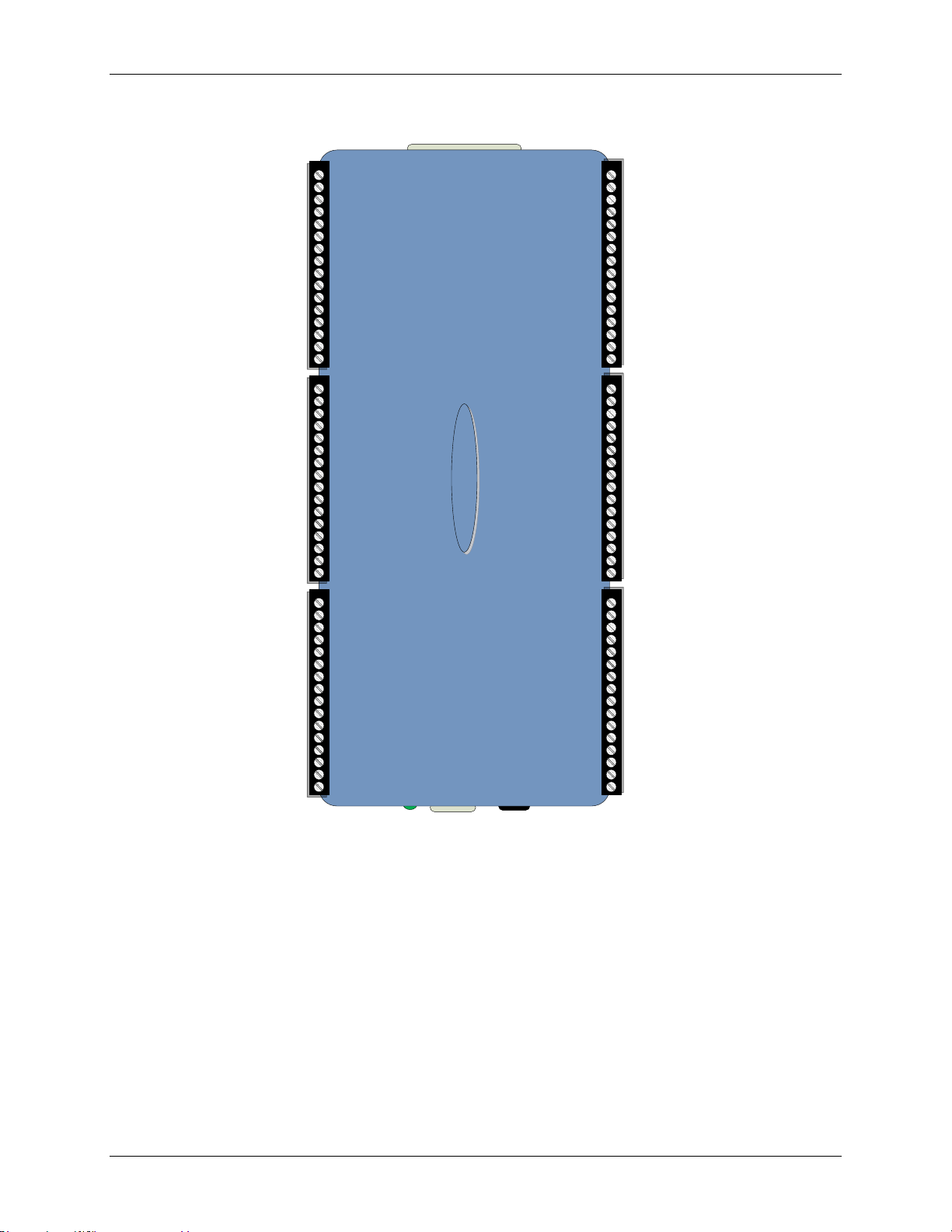
Screw terminal pin out – differential
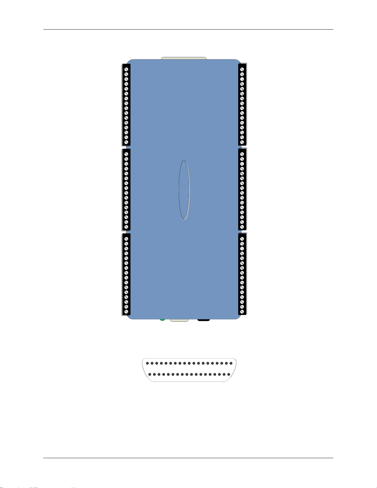
Figure 3. 16-channel differential mode pin out
Differential connection guidelines
When connecting differential voltage inputs to a "floating" voltage source, make sure there is a DC return
path from each voltage input to ground. You make this path by connecting a resistor from each input to a
GND pin (pins 18, 36, 39, 42, 44, 46, 66, 81, 84). A value of approximately 100 kΩ can be used for most
applications.
Leave unused input channels either floating or tied to GND (pins 18, 36, 39, 42, 44, 46, 66, 81, 84).
Source impedances should be kept as small as possible to avoid settling time and accuracy errors.
When configuring thermocouple sensors, keep any stray capacitance as small as possible relative to GND
(pins 18, 36, 39, 42, 44, 46, 66, 81, 84) to avoid settling time and accuracy errors. For thermocouple
channels, do not provide a return path to ground. This is done internally.
11
Page 12
OMB-DAQ-2416 User's Guide Installing the OMB-DAQ-2416
49 NC No connection
50 CH15L Channel 31
51 CH15H Channel 15
52 NC No connection
53 NC No connection
54 CH14L Channel 30
55 CH14H Channel 14
56 NC No connection
57 NC No connection
58 CH13L Channel 29
69 CH13H Channel 13
60 NC No connection
61 NC No connection
62 CH12L Channel 28
63 CH12H Channel 12
64 NC No connection
No connection NC 1
Channel 0 CH0H 2
Channel 16 CH0L 3
No connection NC 4
No connection NC 5
Channel 1 CH1H 6
Channel 17 CH1L 7
No connection NC 8
No connection NC 9
Channel 2 CH2H 10
Channel 18 CH2L 11
No connection NC 12
No connection NC 13
Channel 3 CH3H 14
Channel 19 CH3L 15
No connection NC 16
No connection NC 17
Analog ground GND 18
Channel 4 CH4H 19
Channel 20 CH4L 20
No connection NC 21
No connection NC 22
Channel 5 CH5H 23
Channel 21 CH5L 24
No connection NC 25
No connection NC 26
Channel 6 CH6H 27
Channel 22 CH6L 28
No connection NC 29
No connection NC 30
Channel 7 CH7H 31
Channel 23 CH7L 32
No connection NC 33
No connection NC 34
+5 V output +5V 35
Analog ground GND 36
No connection NC 37
No connection NC 38
Analog ground GND 39
No connection NC 40
No connection NC 41
Analog ground GND 42
Counter input 0 CTR0 43
Analog ground GND 44
Counter input 1 CTR1 45
Analog ground GND 46
No connection NC 47
No connection NC 48
65 NC No connection
66 GND Analog ground
67 CH11L Channel 27
68 CH11H Channel 11
69 NC No connection
70 NC No connection
71 CH10L Channel 26
72 CH10H Channel 10
73 NC No connection
74 NC No connection
75 CH9L Channel 25
76 CH9H Channel 9
77 NC No connection
78 NC No connection
79 CH8L Channel 24
80 CH8H Channel 8
81 GND Analog ground
82 NC No connection
83 NC No connection
84 GND Analog ground
85 DIO7 Digital input/output
86 DIO6 Digital input/output
87 DIO5 Digital input/output
88 DIO4 Digital input/output
89 DIO3 Digital input/output
90 DIO2 Digital input/output
91 DIO1 Digital input/output
92 DIO0 Digital input/output
93 DGND Digital I/O ground
94 DGND Digital I/O ground
95 NC No connection
96 NC No connection
NC.....
NC.....
DIO_LOAD1.....
DIO_LOAD2.....
IMEN7.....
IMEN8.....
IMEN9.....
IMEN10.....
IM_A0.....
IM_A1.....
IM_A2.....
NC.....
NC.....
VCC.....
GND.....
NC.....
GND.....
NC.....
GND.....
......EGND
......NC
......SCK
......MOSI
......SDA
......SCL
......CM_A2
......SM_A0
......SM_A1
......CM_A3
......EXTDIO_INT
......VDD_ISO
......-20.5 V
......AGND
......+20.5 V
......+5 VA
......GND
......+3.3 V_ISO
1 2 3 4 5 6 7 8 9 10 11 12 13 14 15 16 17 18 19
20 21 22 23 24 25 26 27 28 29 30 31 32 33 34 35 36 37
Screw terminal pin out – single-ended
The OMB-AI-EXP32 expansion port is intended to interface directly with the OMB-DAQ-2416. Do not attempt
to use any of the expansion port pins for any other purpose.
Power down the OMB-DAQ-2416 before you connect it the OMB-AI-EXP32 expansion board.
Figure 4. 32-channel single-ended mode pin out
Figure 5. DSUB37 expansion connector pin out
12
Page 13
Analog/TC input screw terminal blocks
· CH 0 – CH 7 differential
· CH 0 – CH 7, CH 16 - CH 23 SE
Counter screw terminal blocks
Activity
LED
Power
LED
USB
connector
External power
connector
Digital I/O screw
terminal blocks
Analog/TC input screw terminal blocks
· CH 8 – CH 15 differential
· CH 8 – CH 31 single-ended
37-pin
expansion connector
Functional Details
This chapter contains detailed information on all of the features available from the board, including:
Device components
Functional block diagram and mechanical drawings
Signal descriptions
Signal diagrams using default or conventional device settings
OMB-DAQ-2416 components
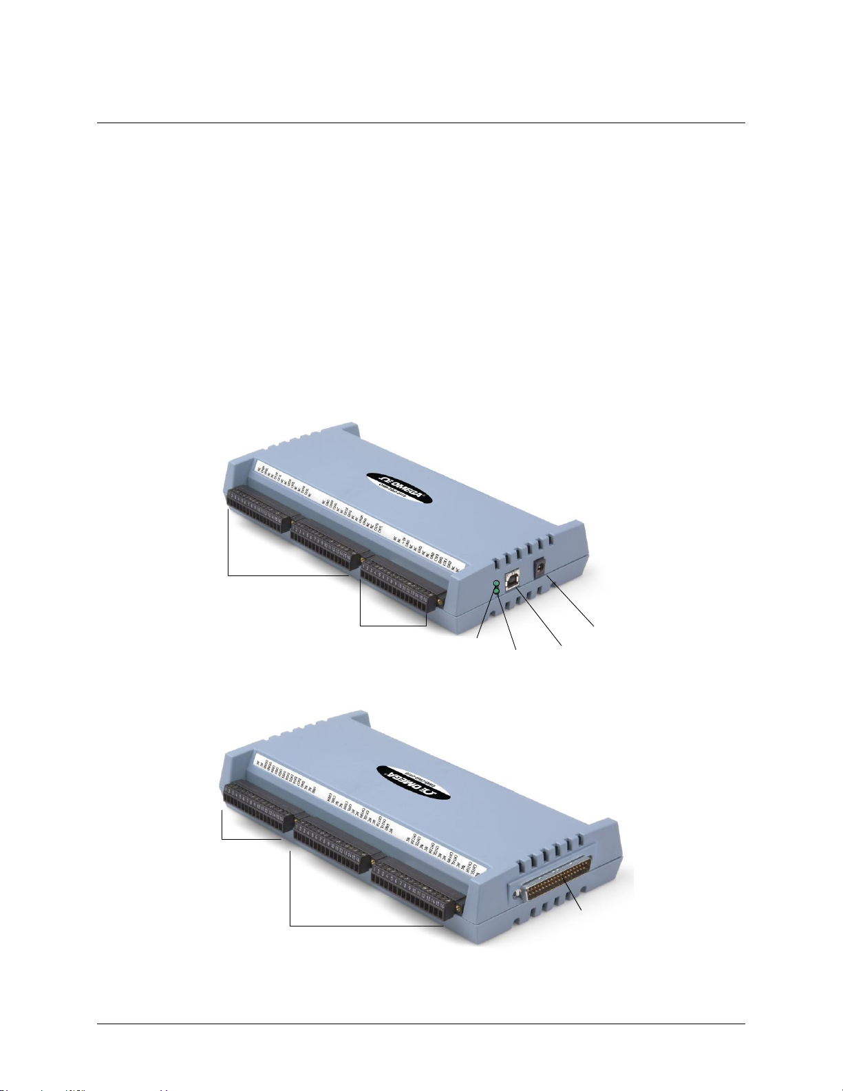
These OMB-DAQ-2416 components are shown in Figure 6 and Figure 7.
One USB connector
One external power connector
Two LED indicators ("Power" and "Activity")
One 37-pin DSUB expansion connector
Six removable screw terminal blocks
Chapter 3
Figure 6. Components – front view
Figure 7. Components – rear view
13
Page 14

OMB-DAQ-2416 User's Guide Functional Details
LEDs
The OMB-DAQ-2416 has two LEDs on the right side of the housing — Power and Activity. The Power LED is
located above the Activity LED. Both LEDs are solid green when the OMB-DAQ-2416 is connected to a
computer.
Power LED
The Power LED blinks when you plug the power supply into the OMB-DAQ-2416, and continues to blink
while the device initializes the hardware. If it continues blinking for more than ½ second, there may be a
problem with the OMB-DAQ-2416, and you should cycle the power. After the device is initialized the LED
remains solid green.
If an application issues a "blink LED" command, then the power LED blinks a few times.
Activity LED
The Activity LED blinks rapidly when both the USB and the external power cables are plugged in. It continues
blinking rapidly while the device is connecting to the computer, and then turns solid.
Whenever the device receives a USB command, the Activity LED blinks off and then returns to solid green.
When an analog in scan is running, the Activity LED blinks continuously.
USB connector
The USB connector is on the right side of the OMB-DAQ-2416 provides communication.
External power connector
Connect the OMB-DAQ-2416-ADAP power supply to this connector. The power supply provides 5 VDC, 10W
regulated power.
Screw terminal wiring
The OMB-DAQ-2416 has six groups of screw terminals—three on each side of the housing. Each group has
16 connections. Pin numbers are identified in Figure 3 on page 11 and Figure 4 on page 12.
14
Page 15
OMB-DAQ-2416 User's Guide Functional Details
4.800
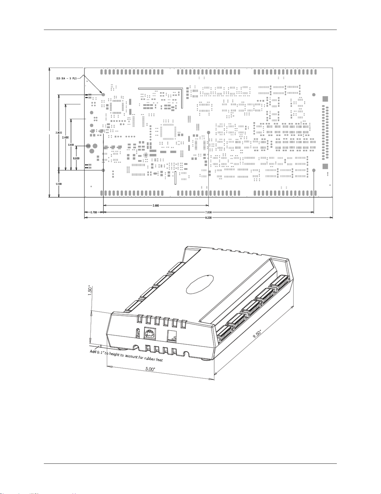
Mechanical drawings
Figure 8. OMB-DAQ-2416 internal dimensions
Figure 9. OMB-DAQ-2416 case dimensions
15
Page 16
OMB-DAQ-2416 User's Guide Functional Details
Block diagram
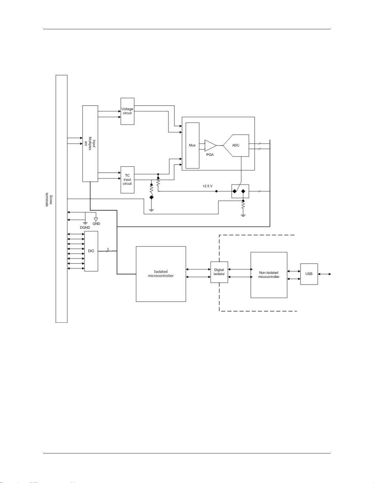
Figure 10 shows a simplified block diagram of the OMB-DAQ-2416. This device provides all of the functional
elements shown in the figure.
Figure 10. OMB-DAQ-2416 functional block diagram
16
Page 17

OMB-DAQ-2416 User's Guide Functional Details
CH0H and CH0L
CH1H and CH1L
CH2H and CH2L
CH3H and CH3L
CH4H and CH4L
CH5H and CH5L
CH6H and CH6L
CH7H and CH7L
CH8H and CH8L
CH9H and CH9L
CH10H and CH10L
CH11H and CH11L
CH12H and CH12L
CH13H and CH13L
CH14H and CH14L
CH15H and CH15L
Analog/TC input terminals
You can connect up to 32 single-ended analog input connections or up to 16 differential analog/TC input
connections to these screw terminal pins.
You can select a unique input range or signal type for each channel. For example, one channel could be used for
volts and another for temperature.
When connecting differential voltage inputs to a "floating" voltage source, make sure there is a DC return path
from each voltage input to ground. You make this path by connecting a resistor from each input to a GND pin
(pins 18, 36, 39, 42, 44, 46, 66, 81, 84). A value of approximately 100 kΩ can be used for most applications.
This does not apply to channels configured for thermocouple input, as they have their own internal reference.
Leave unused input channels either floating or tied to GND (pins 18, 36, 39, 42, 44, 46, 66, 81, 84).
Source impedances should be kept as small as possible to avoid settling time and accuracy errors.
Analog input mode
The OMB-DAQ-2416 makes high-resolution voltage measurements in either a single-ended or fully differential
mode. You can configure the OMB-DAQ-2416 for the following voltage input ranges:
±20 V
±10 V
±5 V
±2.5 V
±1.25 V
±0.625 V
±0.3125 V
±0.15625 V
±0.078125 V
Each analog input channel has the following measurement parameters:
signal type of volts or thermocouple type J, K, T, E, R, S, B, or N
full scale voltage from -20 to + 20 VDC
Thermocouple inputs
You can make up to 16 high-resolution differential thermocouple measurements with the OMB-DAQ-2416.
Built-in cold-junction sensors are provided for each of the screw-terminal blocks, and any supported TC type
can be attached to any of the 16 thermocouple channels.
Do not connect thermocouples as single-ended—doing so can cause false readings.
You do not need to use ground-referencing resistors because the analog front-end circuit level-shifts the
thermocouple's output into the common-mode input range of the A/D.
When configuring thermocouple sensors, keep any stray capacitance as small as possible relative to GND (pins
18, 36, 39, 42, 44, 46, 66, 81, 84) to avoid settling time and accuracy errors.
17
Page 18
OMB-DAQ-2416 User's Guide Functional Details
s
ratedata
640
1
1
The OMB-DAQ-2416 also provides an open thermocouple detection (OTD) feature for each of the analog input
channels configured for thermocouple measurement. This feature is automatically enabled as part of the overall
acquisition process, and detects if an open-circuit condition exists at the thermocouple sensor.
The OMB-DAQ-2416 provides electrostatic discharge (ESD) protection for each of the thermocouple inputs.
However, before handling thermocouple sensors, follow standard ESD practices and discharge any accumulated
ESD charge.
The OMB-DAQ-2416 includes an ESD protection device at each of the analog input terminal block pins. If an
ESD or transient voltage is coupled into the device, the input protection device(s) clamps the voltage to protect
the thermocouple input circuitry from possible damage.
Once the thermocouple sensor is connected to the OMB-DAQ-2416, the configuration options have been
selected, and the recommended 45 minute warm up has elapsed, the OMB-DAQ-2416 is ready to make highresolution differential voltage measurements.
Cold junction compensation (CJC) is needed to compensate for the additional thermal EMF's generated by
connecting the thermocouple leads to the OMB-DAQ-2416 terminal blocks.
CJC is performed using a high-resolution temperature sensor connected close to the OMB-DAQ-2416's terminal
blocks. The OMB-DAQ-2416 includes four separate CJC sensors—two on each side of the PCB. Software
corrects for the additional thermocouples created at the terminal.
Once the A/D and CJC data is collected, the application software uses this data to linearize to an accurate
temperature reading. The thermocouple linearization uses the latest NIST linearization coefficients for each of
the eight thermocouple types supported by the OMB-DAQ-2416.
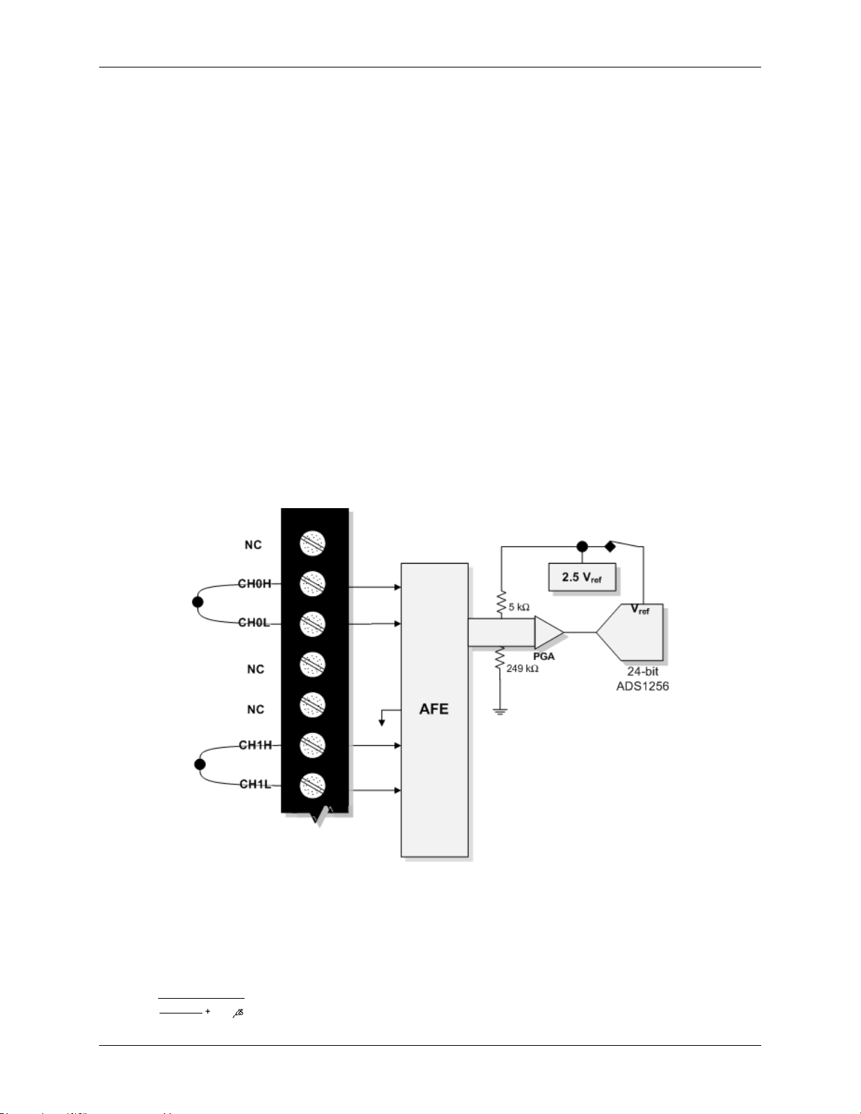
Figure 11 below shows a typical thermocouple connection.
Figure 11. Differential thermocouple connection example
Noise filtering, data rate, and throughput rate
Although the OMB-DAQ-2416's A/D converter has a maximum data rate of 3,750 samples per second, the
actual throughput rate you observe for voltage and temperature data is determined by these formulas.
Maximum single-channel throughput:
18
Page 19
OMB-DAQ-2416 User's Guide Functional Details
n
μs640
ratedata
1
1
Maximum multiple-channel throughput:
where n is the number of channels
Refer to Table 18 and Table 19 of the Specifications chapter for details.
This drop-off in throughput rate is due to the OMB-DAQ-2416's noise filtering feature. You can control the
amount of the noise filtering by adjusting the data rate setting. By reducing the data rate, the averaging of
samples increases, and noise drops correspondingly.
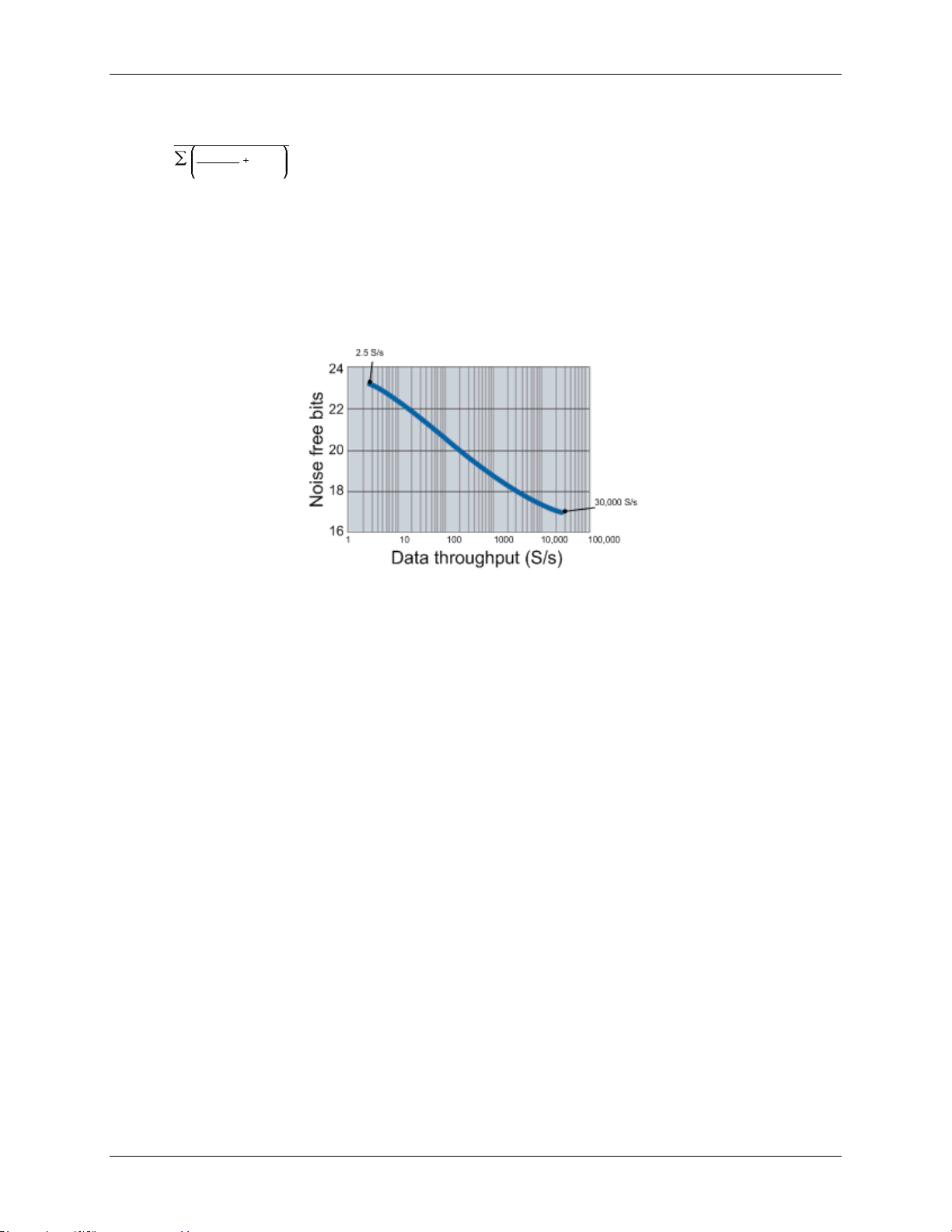
Figure 12 below illustrates this inverse relationship. This graph applies to the A/D converter only—do not
expect this level of performance from the OMB-DAQ-2416 itself.
Figure 12. OMB-DAQ-2416 A/D converter data rate vs. noise graph
If low noise is your main concern, you can operate the OMB-DAQ-2416 at very low data rates starting from 2.5
S/s. At low rates, much of the noise is averaged out of the data, and issues such as reference noise become less
important.
At higher data rates, higher-frequency noise sources are not averaged out and begin to be troublesome. These
noise sources include the noise inherent in the A/D converter itself, which is not reducible.
Since thermocouples can pick up noise in your environment, select a data rate based on the primary noise
frequency. For example, to reduce the effect of 60 Hz noise, select a data rate of 60 (or a sub-multiple of 60,
such as 10 or 20).
Multiple-channel throughput rates
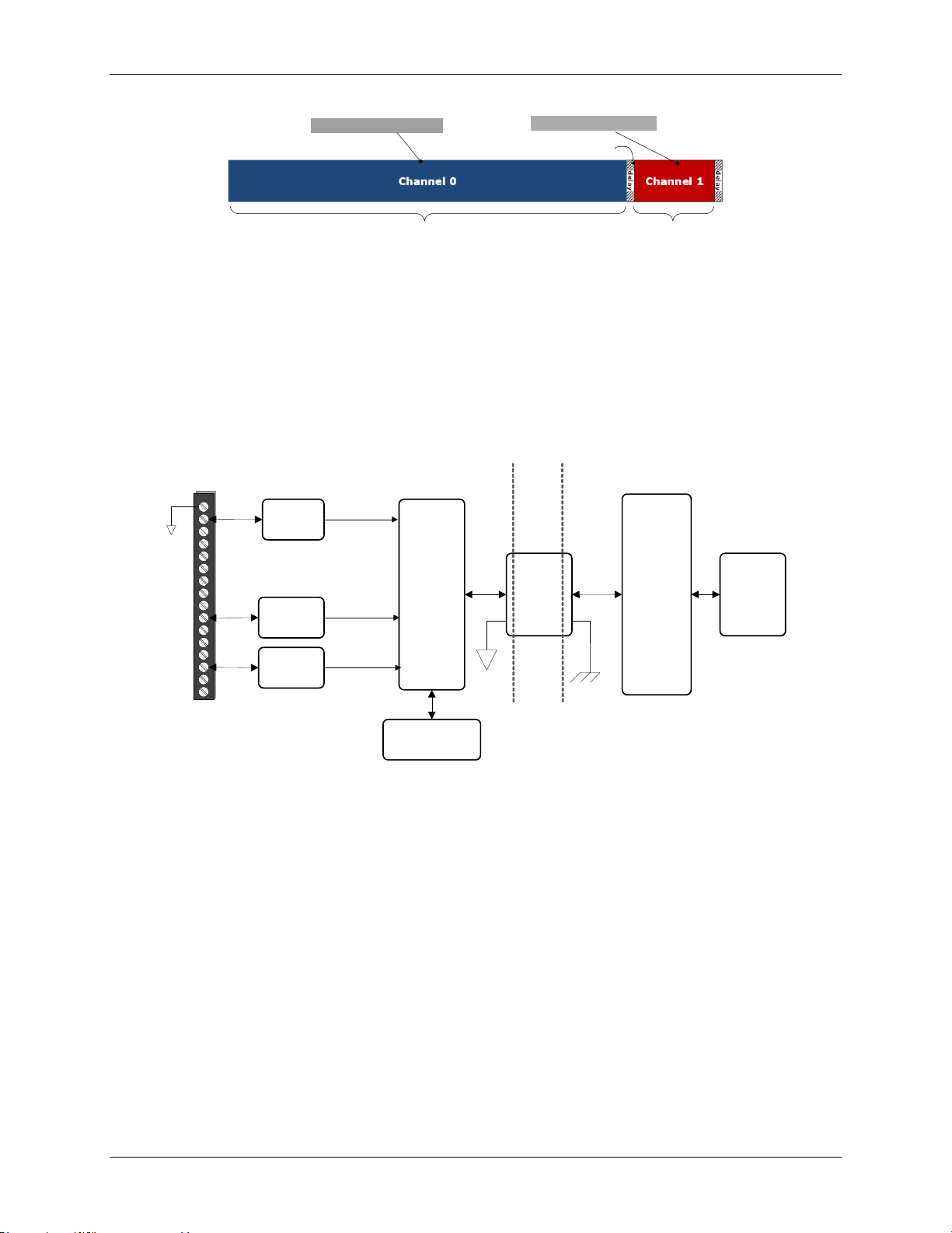
When setting different sample rates for different channels, be aware that the all channels will be sampled within
the same sample window based on the channel with the lowest sample rate.
For example, if you set a 10 Hz data rate for channel 0, and a 50 Hz data rate for channel 1, basically, both
channels pass the same number of samples per second to the host computer. However, more averaging is
performed on channel 0's samples; therefore, channel 0 is sampled at a higher resolution.
The OMB-DAQ-2416's A/D converter performs averaging, and the number of averages equals 30,000/data
rate.
In this example, channel 0 is sampled 3000 times over 100 ms, and all samples are averaged into one sample.
Then, channel 1 is sampled 600 times over 20 ms, and samples are likewise averaged into one sample.
The final samples are available to you at a maximum rate of about 8 Hz (8.245 Hz).
19
Page 20
OMB-DAQ-2416 User's Guide Functional Details
640 µs delay before
next sample taken
Resolution = 20.6 bits
Resolution = 19.6 bits
Isolation
barrier
I/O connector
AIN/TIN
DIO
Counters
Isolated
µC
DSUB-37
connector
(OMB-AI-EXP32)
Digital
isolator
Non-
isolated
µC
USB
Non--isolated
ground
Isolated
ground
Figure 13. OMB-DAQ-2416 data rate vs. resolution example
Input isolation
The OMB-DAQ-2416 is an isolated data acquisition device. The analog input, digital I/O, counters, and all the
digital control/timing are referenced to an isolated ground as shown in the figure below. This ground is
physically and electrically separate from the ground use by the circuit connected to the system bus interface.
Isolation provides a barrier between the host PC and potentially hazardous voltages by physically and
electrically separating two parts of the measurement device.
The "non-isolated" ground is common to the chassis ground of the PC, while the "isolated" ground is not.
All analog measurements are made relative to the isolated ground. See Figure 14 for details.
When making measurements in industrial environments, DAQ devices can encounter hazardous voltages,
transients, large common mode voltages and fluctuating ground potentials. Any one of these issues can
seriously degrade the measurement accuracy of the device and possibly damage the measurement instrument.
To overcome these issues, some DAQ devices provide physical and electrical isolation. Some of the benefits of
isolation include:
Safety: A DAQ device employing physical and electrical isolation helps to keep high voltages and
transients from damaging the system-side host PC.
Ground loops: Improper grounding of the signal source that the DAQ device is measuring is one of the
most common sources of noise and measurement inaccuracies. Isolation improves the measurement
accuracy by physically preventing ground loops. Ground loops—a common source of noise and error—are
the results of a measurement system having multiple grounds at different potentials.
Common mode rejection: With isolation, a DAQ device can measure small signals in the presence of
large common mode voltages. Isolation increases the measurement system's ability to reject common mode
voltages. The common mode voltage is the signal that is common to both the positive and negative inputs
of the measurement device, but is not part of the signal to measure.
Figure 14. Input isolation diagram
20
Page 21
OMB-DAQ-2416 User's Guide Functional Details
Digital I/O
Up to eight digital I/O lines are available in each OMB-DAQ-2416.
Digital input voltage ranges of 0 to +15V are permitted, with thresholds of 0.6 V (low) and 2.6 V (high). Each
DIO channel is an open-drain, which, when used as an output, is capable of sinking up to 150 mA for direct
drive applications. The maximum sink current is 150 mA per 8-channel bank, or if all eight channels are used,
18 mA (maximum) per channel.
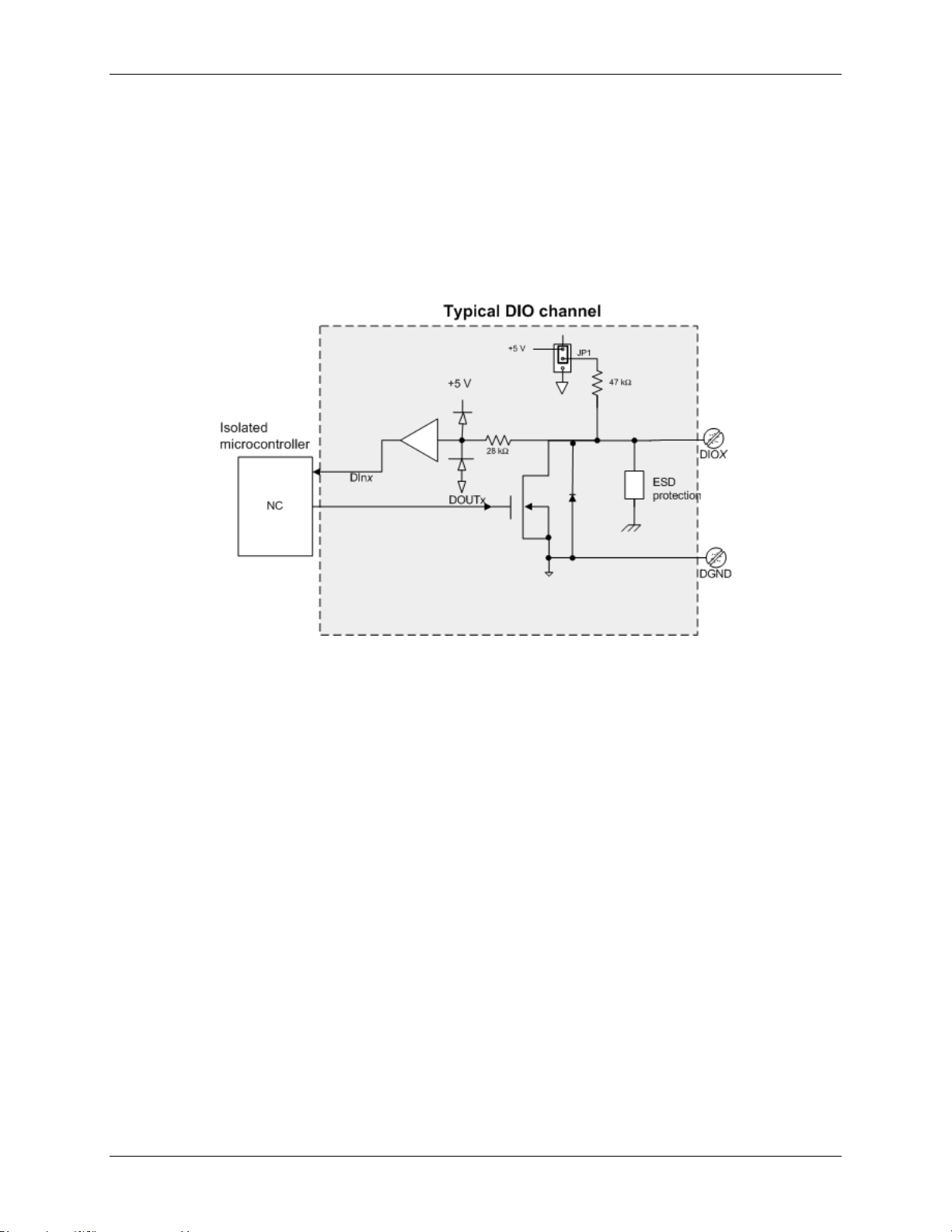
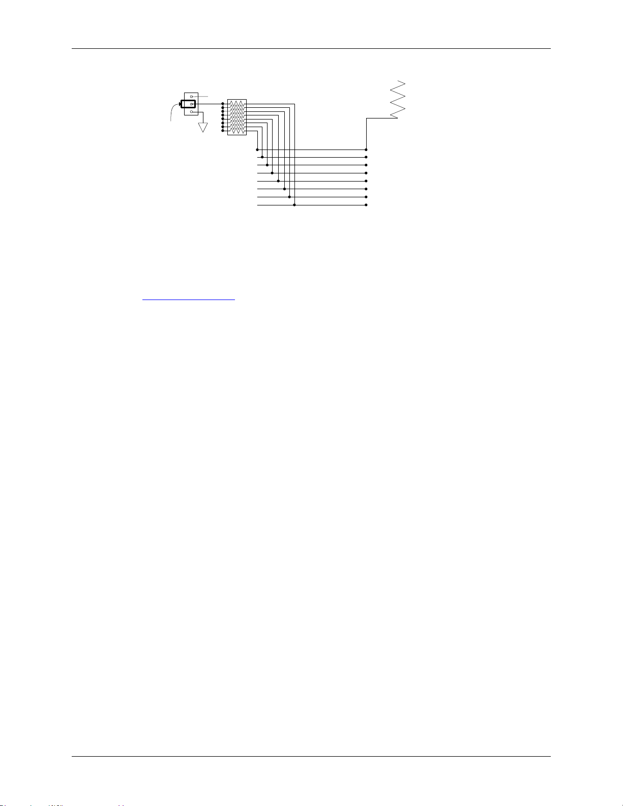
Figure 15 is an example of a typical DIO connection. The figure represents connections for one channel. The
other seven channels are connected in the same manner.
Figure 15. Digital output connection example
Internal pull-up/pull-down capability
Each of the eight DIO bits on the OMB-DAQ-2416 has a 47 kΩ pull-up/pull-down resistor. The pull-up/pulldown voltage is common to all of the internal 47 kΩ resistors.
All pins are pulled up to +5V by default. To configure these bits for the 0V pull-down option, open the OMBDAQ-2416 case to access the three-pin jumper labeled JP1.
To open the case and set the JP1 jumper, do the following.
1. Turn over the OMB-DAQ-2416 and rest it on its top on a flat, stable surface.
2. Remove the five screws shown in Figure 16 from the bottom of the module.
3. Holding both the top and bottom sections of the module, turn it over, rest it on the surface, and carefully
remove the top portion of the case.
21
Page 22
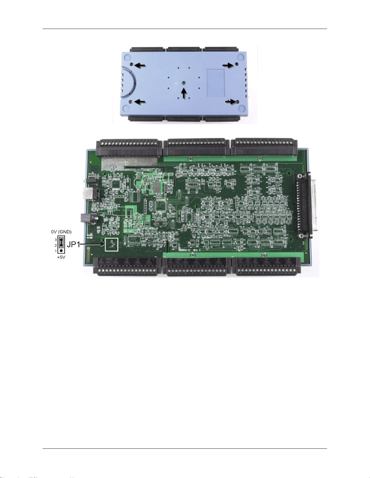
OMB-DAQ-2416 User's Guide Functional Details
Figure 16. Location of screws connecting bottom and top sections of case
Figure 17. Location of JP1
4. To pull the digital pins down to ground, place the shorting block across pins 2 and 3 (refer to the jumper
orientation shown in Figure 17).
To pull the digital pins up to +5V, place the shorting block across pins 1 and 2.
External pull-up/pull-down capability
You can also place an external pull-up resistor on any of the DIO bits. This enables you to pull the DIO bit up to
a voltage that exceeds the internal +5 V pull-up voltage.
When using external pull-up resistors, note the following:
You should either remove the JP1 jumper or store it by attaching it to one of the three pins.
When using external pull-up resistors, the internal resistors cause slight impedance shifts to digital lines in
the "on" state as the number of lines in the "off" state changes.
22
Page 23
OMB-DAQ-2416 User's Guide Functional Details
47 kΩ
DIO0
DIO1
DIO2
DIO3
DIO4
DIO5
DIO6
DIO7
+5 V
+ V
External pull-up resistor
JP1
Internal jumper
disabled (placed on
center pin only)
Figure 18. Digital I/O external resistor configuration
Counter input terminals (CTR0, CTR1)
Two 32-bit event counters are built into the OMB-DAQ-2416. Each counter accepts frequency inputs up to
1 MHz.
Refer to the Screw terminal pin out diagrams starting on page 11 for the location of these pins. The internal
counter increments when the TTL levels transition from low to high. The counter can count frequencies of up to
1 MHz.
23
Page 24

Chapter 4
Calibrating the OMB-DAQ-2416
The OMB-DAQ-2416 is initially calibrated using an NIST-traceable calibration method. This method stores a
correction factor for each AIN range in non-volatile memory on the device at the time of calibration.
Allow a 45 minute warm-up period before calibrating the OMB-DAQ-2416.
Calibration methods
Factory calibration
You can return the OMB-DAQ-2416 once a year to Omega Engineering for a new factory calibration and
calibration certificate.
Self calibration
Use InstaCal to calibrate the OMB-DAQ-2416 whenever the ambient temperature changes by more than ±10 °C
from the last self-calibration
You can perform this procedure with thermocouple and voltage inputs connected to the input terminal blocks.
24
Page 25
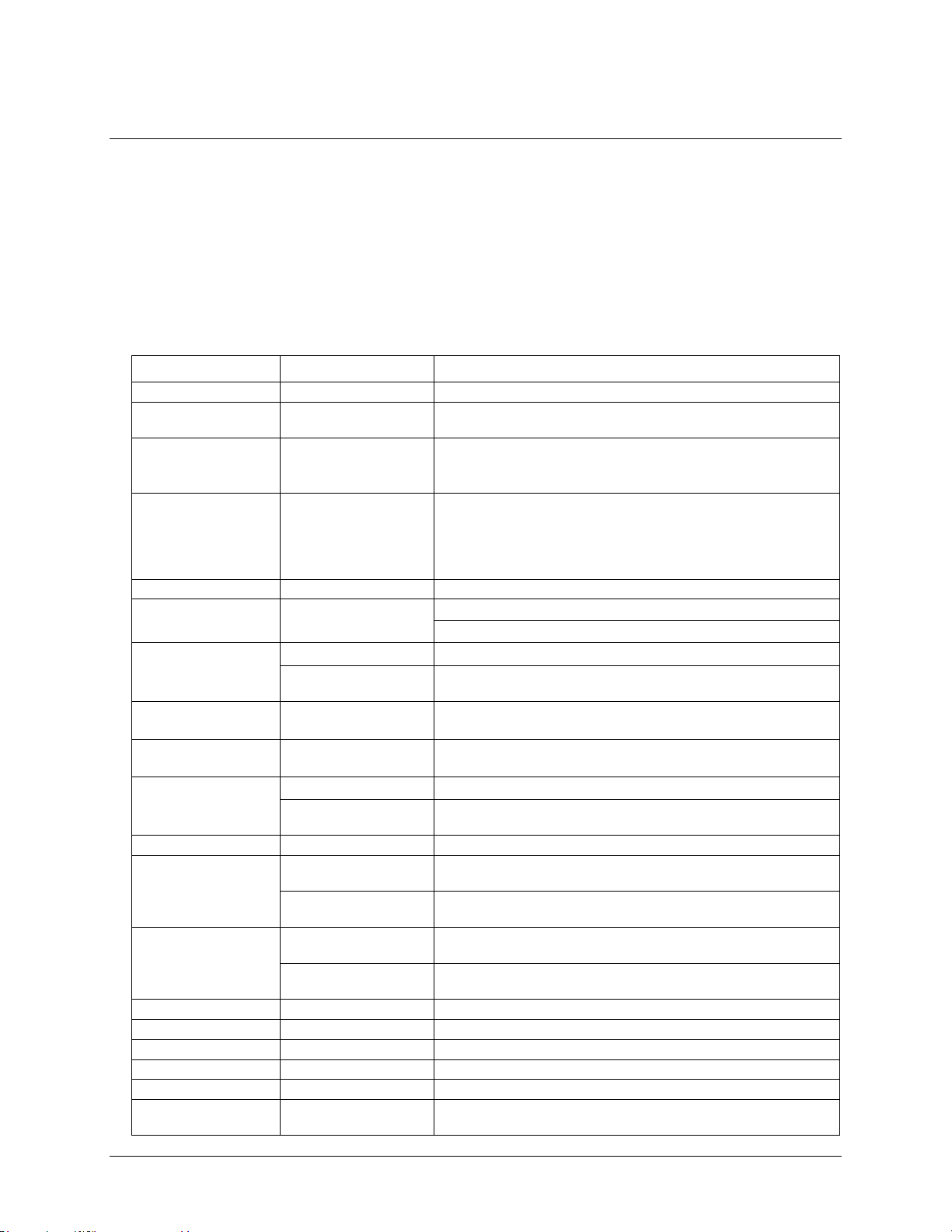
Parameter
Conditions
Specification
A/D converter type
ADS1256, 24-bit Sigma Delta
A/D data rates
3750 samples per second (S/s), 2000 S/s, 1000 S/s, 500 S/s, 100 S/s,
60 S/s, 50 S/s, 25 S/s, 10 S/s, 5 S/s, 2.5 S/s
Throughput
Single channel: 2.5 Hz to 1102.94 Hz, software selectable
Multiple channels: 0.16 Hz to 1102.94 Hz, software selectable
(see tables 18 and 19 for details)
Number of channels
Up to 32 channels individually software-configurable as
single-ended or differential
Thermocouples require differential mode. For each channel
configured as differential, you essentially lose one single-ended
channel. Add channels by connecting to an OMB-AI-EXP32.
Input isolation
500 VDC minimum between field wiring and USB interface
Channel configurations
Temperature sensor input, s/w programmable to match sensor type
Voltage input
Input voltage range
Thermocouple mode
±0.078125 V
Voltage mode (Note 1)
±20 V, ±10 V, ±5 V, ±2.5 V, ±1.25 V, ±0.625 V, ±0.3125 V,
±0.15625 V, ±0.078125 V, software-configurable
Absolute maximum
input voltage
CxH-CxL relative to
GND
±30 V maximum (power on)
±10 V maximum (power off)
Input impedance
2 GΩ (power on)
390Ω (power off)
Input leakage current
±10.6 nA
Input voltage >±30 V
(power on/off)
±1 µA maximum
Input capacitance
590 pf
Maximum working
voltage (signal +
common mode)
Voltage mode: ±20V
range
±20.01 V maximum
Voltage mode: all other
voltage input ranges
±10.25 V maximum
Common mode
rejection ratio (Note 1)
Thermocouple mode,
(fIN = 60 Hz)
110 dB
Voltage mode,(fIN =
60 Hz, all input ranges)
90 dB
ADC resolution
24 bits
Crosstalk
Adjacent channels
100 dB
Input coupling
DC
Channel gain queue
Up to 64 elements
Software configurable channel and range
Warm-up time
45 minutes minimum
Open thermocouple
detect
Automatically enabled when the channel is configured for a
thermocouple sensor.
Chapter 5
Specifications
All specifications are subject to change without notice.
Typical for 25 °C unless otherwise specified.
All specifications apply to all temperature and voltage input channels unless otherwise specified.
Specifications in italic text are guaranteed by design.
Analog input
Table 1. General analog input specifications
25
Page 26
OMB-DAQ-2416 User's Guide Specifications
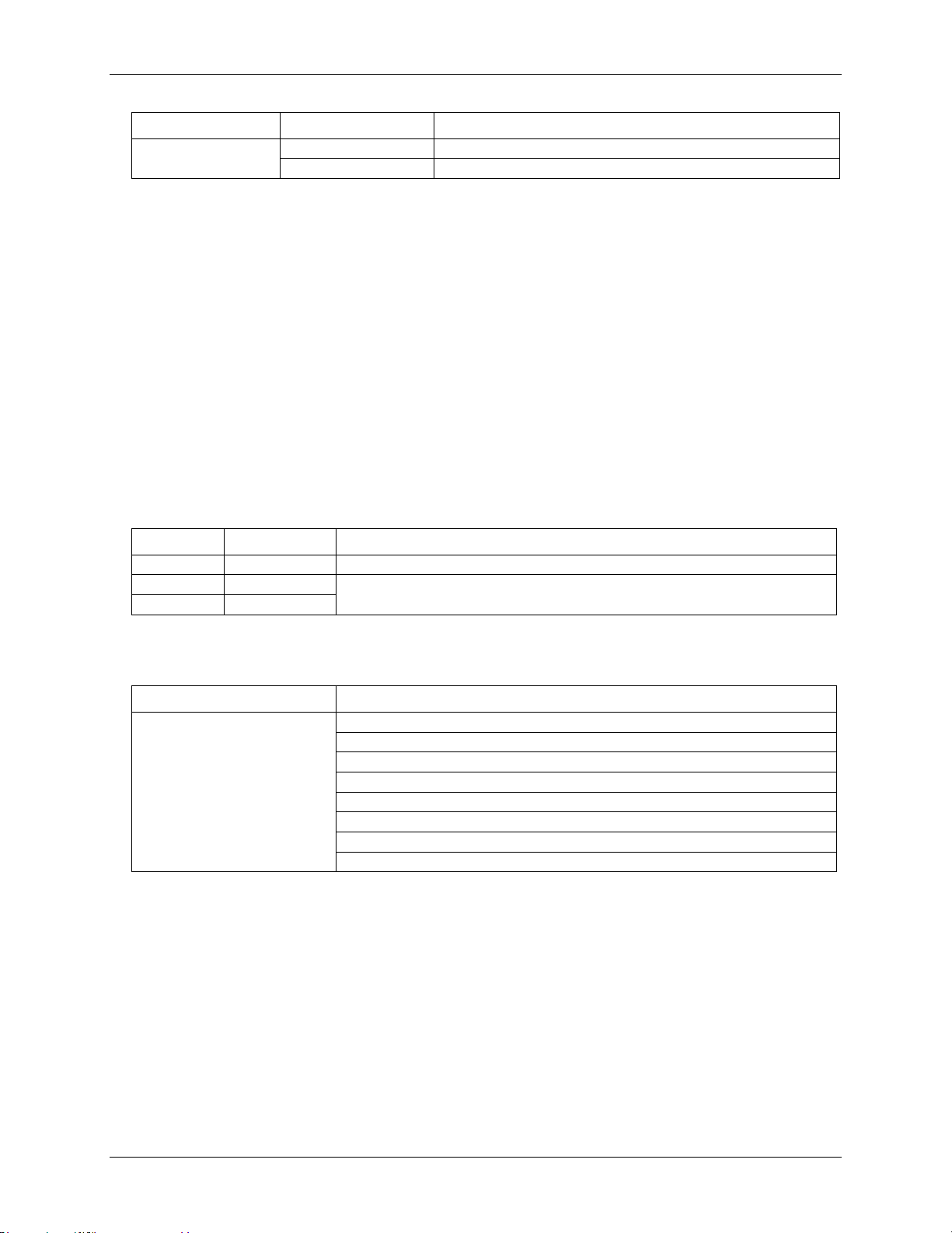
Parameter
Conditions
Specification
CJC sensor accuracy
15 °C to 35 °C
±0.15 °C typical
0 °C to 55 °C
±0.5 °C maximum
Channel
Category
Specification
CxH/CxL
Thermocouple
16 differential channels
CxH/CxL
Voltage
32 individually-configurable channels that can be configured as either single-ended or
differential.
CxH/CxL
Voltage
Parameter
Conditions
Thermocouple
J: -210 °C to 1200 °C
K: -270 °C to 1372 °C
R: -50 °C to 1768 °C
S: -50 °C to 1768 °C
T: -270 °C to 400 °C
N: -270 °C to 1300 °C
E: -270 °C to 1000 °C
B: 0 °C to 1820 °C
Note 1: Placing a notch of the A/D digital filter at 60 Hz (setting A/D data rate = 60 S/s, 10 S/s, 5 S/s or
2.5 S/s) further improves the common mode rejection of this frequency.
Channel configurations
When any item is changed, the firmware stores channel configurations in the EEPROM of the isolated
microcontroller. An external application issues commands over the USB to make changes, and the configuration
is made non-volatile through the use of the EEPROM.
When connecting differential voltage inputs to a floating voltage source, provide a DC return path from each
voltage input to ground. To do this, connect a resistor from each input to a GND pin (pins 18, 36, 39, 42, 44, 46,
66, 81, 84). A value of approximately 100 kΩ can be used for most applications.
Leave unused input channels either floating or tied to GND (pins 18, 36, 39, 42, 44, 46, 66, 81, 84).
Source impedances should be kept as small as possible to avoid settling time and accuracy errors.
For each voltage/thermocouple channel configured as differential, you essentially lose one single-ended
channel. You can add channels by connecting to an OMB-AI-EXP32.
Table 2. Channel configurations
Compatible sensors
Table 3. Compatible sensor type specifications
Accuracy
Thermocouple measurement accuracy
Thermocouple measurement accuracy specifications include polynomial linearization error, cold-junction
compensation measurement error, and system noise. These specs are for one year, or 3000 operating hours,
whichever comes first.
There is a CJC sensor for each terminal block of the module. The accuracy listed below assumes the screw
terminals are at the same temperature as the CJC sensor.
The accuracy errors shown do not include the inherent accuracy error of the thermocouple sensor itself. Contact
your thermocouple supplier for details on the actual thermocouple sensor accuracy limitations.
26
Page 27
OMB-DAQ-2416 User's Guide Specifications
A/D data rate
Sensor temperature range
Accuracy error
maximum
Accuracy error
typical
Tempco
(°C/°C)
3750 S/s
-210 °C
2.572 °C
1.416 °C
0.022
0 °C
0.935 °C
0.469 °C
1200 °C
1.869 °C
1.456 °C
2000 S/s
-210 °C
2.572 °C
1.416 °C
0.022
0 °C
0.935 °C
0.469 °C
1200 °C
1.869 °C
1.456 °C
1000 S/s
-210 °C
2.572 °C
1.416 °C
0.022
0 °C
0.935 °C
0.469 °C
1200 °C
1.869 °C
1.456 °C
500 S/s
-210 °C
2.442 °C
1.334 °C
0.022
0 °C
0.881 °C
0.415 °C
1200 °C
1.821 °C
1.408 °C
100 S/s
-210 °C
2.442 °C
1.334 °C
0.022
0 °C
0.881 °C
0.415 °C
1200 °C
1.821 °C
1.408 °C
60 S/s
-210 °C
2.442 °C
1.334 °C
0.022
0 °C
0.881 °C
0.415 °C
1200 °C
1.821 °C
1.408 °C
50 S/s
-210 °C
2.442 °C
1.334 °C
0.022
0 °C
0.881 °C
0.415 °C
1200 °C
1.821 °C
1.408 °C
25 S/s
-210 °C
2.442 °C
1.334 °C
0.022
0 °C
0.881 °C
0.415 °C
1200 °C
1.821 °C
1.408 °C
10 S/s
-210 °C
2.442 °C
1.334 °C
0.022
0 °C
0.881 °C
0.415 °C
1200 °C
1.821 °C
1.408 °C
5 S/s
-210 °C
2.442 °C
1.334 °C
0.022
0 °C
0.881 °C
0.415 °C
1200 °C
1.821 °C
1.408 °C
2.5 S/s
-210 °C
2.442 °C
1.334 °C
0.022
0 °C
0.881 °C
0.415 °C
1200 °C
1.821 °C
1.408 °C
Connect thermocouples to the OMB-DAQ-2416 such that they are floating with respect to GND (pins 18, 36,
39, 42, 44, 46, 66, 81, 84, 93, and 94).
When configuring thermocouple sensors, keep any stray capacitance relative to GND (pins 18, 36, 39, 42, 44,
46, 66, 81, 84) as small as possible to avoid settling time and accuracy errors.
The OMB-DAQ-2416 GND and DGND pins are isolated from earth ground. You can connect thermocouple
sensors to voltages referenced to earth ground as long as isolation between the GND/DGND pins and earth
ground is maintained.
Table 4. J type thermocouple accuracy specifications, including CJC measurement error.
All specifications are (±).
To achieve the thermocouple accuracies listed above, the OMB-DAQ-2416 should be warmed up for
45 minutes after the initial power on. The accuracies listed above are only guaranteed if the OMB-DAQ-2416 is
housed in its plastic enclosure.
27
Page 28
OMB-DAQ-2416 User's Guide Specifications
A/D data rate
Sensor
temperature range
Accuracy error
maximum
Accuracy error
typical
Tempco
(°C/°C)
3750 S/s
-210 °C
2.917 °C
1.699 °C
0.029
0 °C
1.017 °C
0.526 °C
1372 °C
2.478 °C
2.022 °C
2000 S/s
-210 °C
2.917 °C
1.699 °C
0.029
0 °C
1.017 °C
0.526 °C
1372 °C
2.478 °C
2.022 °C
1000 S/s
-210 °C
2.917 °C
1.699 °C
0.029
0 °C
1.017 °C
0.526 °C
1372 °C
2.478 °C
2.022 °C
500 S/s
-210 °C
2.735 °C
1.524 °C
0.029
0 °C
0.948 °C
0.457 °C
1372 °C
2.396 °C
1.941 °C
100 S/s
-210 °C
2.735 °C
1.524 °C
0.029
0 °C
0.948 °C
0.457 °C
1372 °C
2.396 °C
1.941 °C
60 S/s
-210 °C
2.735 °C
1.524 °C
0.029
0 °C
0.948 °C
0.457 °C
1372 °C
2.396 °C
1.941 °C
50 S/s
-210 °C
2.735 °C
1.524 °C
0.029
0 °C
0.948 °C
0.457 °C
1372 °C
2.396 °C
1.941 °C
25 S/s
-210 °C
2.735 °C
1.524 °C
0.029
0 °C
0.948 °C
0.457 °C
1372 °C
2.396 °C
1.941 °C
10 S/s
-210 °C
2.735 °C
1.524 °C
0.029
0 °C
0.948 °C
0.457 °C
1372 °C
2.396 °C
1.941 °C
5 S/s
-210 °C
2.735 °C
1.524 °C
0.029
0 °C
0.948 °C
0.457 °C
1372 °C
2.396 °C
1.941 °C
2.5 S/s
-210 °C
2.735 °C
1.524 °C
0.029
0 °C
0.948 °C
0.457 °C
1372 °C
2.396 °C
1.941 °C
Table 5. K type thermocouple accuracy specifications, including CJC measurement error.
All specifications are (±).
To achieve the thermocouple accuracies listed above, the OMB-DAQ-2416 should be warmed up for
45 minutes after the initial power on. The accuracies listed above are only guaranteed if the OMB-DAQ-2416 is
housed in its plastic enclosure.
28
Page 29
OMB-DAQ-2416 User's Guide Specifications
A/D data rate
Sensor
temperature range
Accuracy error
maximum
Accuracy error
typical
Tempco
(°C/°C)
3750 S/s
-200 °C
3.480°C
2.030 °C
0.029
0 °C
1.201 °C
0.659 °C
1300 °C
1.991 °C
1.600 °C
2000 S/s
-200 °C
3.480°C
2.030 °C
0.029
0 °C
1.201 °C
0.659 °C
1300 °C
1.991 °C
1.600 °C
1000 S/s
-200 °C
3.480°C
2.030 °C
0.029
0 °C
1.201 °C
0.659 °C
1300 °C
1.991 °C
1.600 °C
500 S/s
-200 °C
3.196°C
1.750 °C
0.029
0 °C
1.096 °C
0.553 °C
1300 °C
1.915 °C
1.524 °C
100 S/s
-200 °C
3.196°C
1.750 °C
0.029
0 °C
1.096 °C
0.553 °C
1300 °C
1.915 °C
1.524 °C
60 S/s
-200 °C
3.196°C
1.750 °C
0.029
0 °C
1.096 °C
0.553 °C
1300 °C
1.915 °C
1.524 °C
50 S/s
-200 °C
3.196°C
1.750 °C
0.029
0 °C
1.096 °C
0.553 °C
1300 °C
1.915 °C
1.524 °C
25 S/s
-200 °C
3.196°C
1.750 °C
0.029
0 °C
1.096 °C
0.553 °C
1300 °C
1.915 °C
1.524 °C
10 S/s
-200 °C
3.196°C
1.750 °C
0.029
0 °C
1.096 °C
0.553 °C
1300 °C
1.915 °C
1.524 °C
5 S/s
-200 °C
3.196°C
1.750 °C
0.029
0 °C
1.096 °C
0.553 °C
1300 °C
1.915 °C
1.524 °C
2.5 S/s
-200 °C
3.196°C
1.750 °C
0.029
0 °C
1.096 °C
0.553 °C
1300 °C
1.915 °C
1.524 °C
Table 6. N type thermocouple accuracy specifications, including CJC measurement error.
All specifications are (±).
To achieve the thermocouple accuracies listed above, the OMB-DAQ-2416 should be warmed up for
45 minutes after the initial power on. The accuracies listed above are only guaranteed if the OMB-DAQ-2416 is
housed in its plastic enclosure.
29
Page 30
OMB-DAQ-2416 User's Guide Specifications
A/D data rate
Sensor
temperature range
Accuracy error
maximum
Accuracy error
typical
Tempco
(°C/°C)
3750 S/s
-50 °C
4.826 °C
3.133 °C
0.082
250 °C
2.117 °C
1.424 °C
1768 °C
2.842 °C
2.347 °C
2000 S/s
-50 °C
4.826 °C
3.133 °C
0.082
250 °C
2.117 °C
1.424 °C
1768 °C
2.842 °C
2.347 °C
1000 S/s
-50 °C
4.826 °C
3.133 °C
0.082
250 °C
2.117 °C
1.424 °C
1768 °C
2.842 °C
2.347 °C
500 S/s
-50 °C
4.065 °C
2.379 °C
0.082
250 °C
1.805 °C
1.113 °C
1768 °C
2.619 °C
2.123 °C
100 S/s
-50 °C
4.065 °C
2.379 °C
0.082
250 °C
1.805 °C
1.113 °C
1768 °C
2.619 °C
2.123 °C
60 S/s
-50 °C
4.065 °C
2.379 °C
0.082
250 °C
1.805 °C
1.113 °C
1768 °C
2.619 °C
2.123 °C
50 S/s
-50 °C
4.065 °C
2.379 °C
0.082
250 °C
1.805 °C
1.113 °C
1768 °C
2.619 °C
2.123 °C
25 S/s
-50 °C
4.065 °C
2.379 °C
0.082
250 °C
1.805 °C
1.113 °C
1768 °C
2.619 °C
2.123 °C
10 S/s
-50 °C
4.065 °C
2.379 °C
0.082
250 °C
1.805 °C
1.113 °C
1768 °C
2.619 °C
2.123 °C
5 S/s
-50 °C
4.065 °C
2.379 °C
0.082
250 °C
1.805 °C
1.113 °C
1768 °C
2.619 °C
2.123 °C
2.5 S/s
-50 °C
4.065 °C
2.379 °C
0.082
250 °C
1.805 °C
1.113 °C
1768 °C
2.619 °C
2.123 °C
Table 7. R type thermocouple accuracy specifications, including CJC measurement error.
All specifications are (±).
To achieve the thermocouple accuracies listed above, the OMB-DAQ-2416 should be warmed up for
45 minutes after the initial power on. The accuracies listed above are only guaranteed if the OMB-DAQ-2416 is
housed in its plastic enclosure.
30
Page 31
OMB-DAQ-2416 User's Guide Specifications
A/D data rate
Sensor
temperature range
Accuracy error
maximum
Accuracy error
typical
Tempco
(°C/°C)
3750 S/s
-50 °C
4.510 °C
2.930 °C
0.088
250 °C
2.165 °C
1.468 °C
1768 °C
3.187 °C
2.597 °C
2000 S/s
-50 °C
4.510 °C
2.930 °C
0.088
250 °C
2.165 °C
1.468 °C
1768 °C
3.187 °C
2.597 °C
1000 S/s
-50 °C
4.510 °C
2.930 °C
0.088
250 °C
2.165 °C
1.468 °C
1768 °C
3.187 °C
2.597 °C
500 S/s
-50 °C
3.798 °C
2.226 °C
0.088
250 °C
1.853 °C
1.156 °C
1768 °C
2.922 °C
2.332 °C
100 S/s
-50 °C
3.798 °C
2.226 °C
0.088
250 °C
1.853 °C
1.156 °C
1768 °C
2.922 °C
2.332 °C
60 S/s
-50 °C
3.798 °C
2.226 °C
0.088
250 °C
1.853 °C
1.156 °C
1768 °C
2.922 °C
2.332 °C
50 S/s
-50 °C
3.798 °C
2.226 °C
0.088
250 °C
1.853 °C
1.156 °C
1768 °C
2.922 °C
2.332 °C
25 S/s
-50 °C
3.798 °C
2.226 °C
0.088
250 °C
1.853 °C
1.156 °C
1768 °C
2.922 °C
2.332 °C
10 S/s
-50 °C
3.798 °C
2.226 °C
0.088
250 °C
1.853 °C
1.156 °C
1768 °C
2.922 °C
2.332 °C
5 S/s
-50 °C
3.798 °C
2.226 °C
0.088
250 °C
1.853 °C
1.156 °C
1768 °C
2.922 °C
2.332 °C
2.5 S/s
-50 °C
3.798 °C
2.226 °C
0.088
250 °C
1.853 °C
1.156 °C
1768 °C
2.922 °C
2.332 °C
Table 8. S type thermocouple accuracy specifications, including CJC measurement error.
All specifications are (±).
To achieve the thermocouple accuracies listed above, the OMB-DAQ-2416 should be warmed up for
45 minutes after the initial power on. The accuracies listed above are only guaranteed if the OMB-DAQ-2416 is
housed in its plastic enclosure.
31
Page 32
OMB-DAQ-2416 User's Guide Specifications
A/D data rate
Sensor
temperature range
Accuracy error
maximum
Accuracy error
typical
Tempco
(°C/°C)
3750 S/s
250 °C
5.489 °C
3.956 °C
0.14
700 °C
2.283 °C
1.743 °C
1820 °C
2.202 °C
1.842 °C
2000 S/s
250 °C
5.489 °C
3.956 °C
0.14
700 °C
2.283 °C
1.743 °C
1820 °C
2.202 °C
1.842 °C
1000 S/s
250 °C
5.489 °C
3.956 °C
0.14
700 °C
2.283 °C
1.743 °C
1820 °C
2.202 °C
1.842 °C
500 S/s
250 °C
4.387 °C
2.885 °C
0.14
700 °C
1.879 °C
1.340 °C
1820 °C
1.962 °C
1.601 °C
100 S/s
250 °C
4.387 °C
2.885 °C
0.14
700 °C
1.879 °C
1.340 °C
1820 °C
1.962 °C
1.601 °C
60 S/s
250 °C
4.387 °C
2.885 °C
0.14
700 °C
1.879 °C
1.340 °C
1820 °C
1.962 °C
1.601 °C
50 S/s
250 °C
4.387 °C
2.885 °C
0.14
700 °C
1.879 °C
1.340 °C
1820 °C
1.962 °C
1.601 °C
25 S/s
250 °C
4.387 °C
2.885 °C
0.14
700 °C
1.879 °C
1.340 °C
1820 °C
1.962 °C
1.601 °C
10 S/s
250 °C
4.387 °C
2.885 °C
0.14
700 °C
1.879 °C
1.340 °C
1820 °C
1.962 °C
1.601 °C
5 S/s
250 °C
4.387 °C
2.885 °C
0.14
700 °C
1.879 °C
1.340 °C
1820 °C
1.962 °C
1.601 °C
2.5 S/s
250 °C
4.387 °C
2.885 °C
0.14
700 °C
1.879 °C
1.340 °C
1820 °C
1.962 °C
1.601 °C
Table 9. B type thermocouple accuracy specifications, including CJC measurement error.
All specifications are (±).
To achieve the thermocouple accuracies listed above, the OMB-DAQ-2416 should be warmed up for
45 minutes after the initial power on. The accuracies listed above are only guaranteed if the OMB-DAQ-2416 is
housed in its plastic enclosure.
32
Page 33
OMB-DAQ-2416 User's Guide Specifications
A/D data
rate
Sensor temperature
range
Accuracy error
maximum
Accuracy error typical
Tempco
(°C/°C)
3750 S/s
-200 °C
2.413 °C
1.352 °C
0.017
0 °C
1.069 °C
0.551 °C
1000 °C
1.575 °C
1.211 °C
2000 S/s
-200 °C
2.413 °C
1.352 °C
0.017
0 °C
1.069 °C
0.551 °C
1000 °C
1.575 °C
1.211 °C
1000 S/s
-200 °C
2.413 °C
1.352 °C
0.017
0 °C
1.069 °C
0.551 °C
1000 °C
1.575 °C
1.211 °C
500 S/s
-200 °C
2.306 °C
1.244 °C
0.017
0 °C
1.017 °C
0.499 °C
1000 °C
1.539 °C
1.175 °C
100 S/s
-200 °C
2.306 °C
1.244 °C
0.017
0 °C
1.017 °C
0.499 °C
1000 °C
1.539 °C
1.175 °C
60 S/s
-200 °C
2.306 °C
1.244 °C
0.017
0 °C
1.017 °C
0.499 °C
1000 °C
1.539 °C
1.175 °C
50 S/s
-200 °C
2.306 °C
1.244 °C
0.017
0 °C
1.017 °C
0.499 °C
1000 °C
1.539 °C
1.175 °C
25 S/s
-200 °C
2.306 °C
1.244 °C
0.017
0 °C
1.017 °C
0.499 °C
1000 °C
1.539 °C
1.175 °C
10 S/s
-200 °C
2.306 °C
1.244 °C
0.017
0 °C
1.017 °C
0.499 °C
1000 °C
1.539 °C
1.175 °C
5 S/s
-200 °C
2.306 °C
1.244 °C
0.017
0 °C
1.017 °C
0.499 °C
1000 °C
1.539 °C
1.175 °C
2.5 S/s
-200 °C
2.306 °C
1.244 °C
0.017
0 °C
1.017 °C
0.499 °C
1000 °C
1.539 °C
1.175 °C
Table 10. E type thermocouple accuracy specifications, including CJC measurement error.
All specifications are (±).
To achieve the thermocouple accuracies listed above, the OMB-DAQ-2416 should be warmed up for
45 minutes after the initial power on. The accuracies listed above are only guaranteed if the OMB-DAQ-2416 is
housed in its plastic enclosure.
33
Page 34
OMB-DAQ-2416 User's Guide Specifications
A/D data rate
Sensor
temperature range
Accuracy error
maximum
Accuracy error
typical
Tempco
(°C/°C)
3750 S/s
-200 °C
2.821 °C
1.676 °C
0.027
0 °C
1.050 °C
0.558 °C
400 °C
0.957 °C
0.595 °C
2000 S/s
-200 °C
2.821 °C
1.676 °C
0.027
0 °C
1.050 °C
0.558 °C
400 °C
0.957 °C
0.595 °C
1000 S/s
-200 °C
2.821 °C
1.676 °C
0.027
0 °C
1.050 °C
0.558 °C
400 °C
0.957 °C
0.595 °C
500 S/s
-200 °C
2.644 °C
1.505 °C
0.027
0 °C
0.979 °C
0.487 °C
400 °C
0.912 °C
0.551 °C
100 S/s
-200 °C
2.644 °C
1.505 °C
0.027
0 °C
0.979 °C
0.487 °C
400 °C
0.912 °C
0.551 °C
60 S/s
-200 °C
2.644 °C
1.505 °C
0.027
0 °C
0.979 °C
0.487 °C
400 °C
0.912 °C
0.551 °C
50 S/s
-200 °C
2.644 °C
1.505 °C
0.027
0 °C
0.979 °C
0.487 °C
400 °C
0.912 °C
0.551 °C
25 S/s
-200 °C
2.644 °C
1.505 °C
0.027
0 °C
0.979 °C
0.487 °C
400 °C
0.912 °C
0.551 °C
10 S/s
-200 °C
2.644 °C
1.505 °C
0.027
0 °C
0.979 °C
0.487 °C
400 °C
0.912 °C
0.551 °C
5 S/s
-200 °C
2.644 °C
1.505 °C
0.027
0 °C
0.979 °C
0.487 °C
400 °C
0.912 °C
0.551 °C
2.5 S/s
-200 °C
2.644 °C
1.505 °C
0.027
0 °C
0.979 °C
0.487 °C
400 °C
0.912 °C
0.551 °C
Table 11. T type thermocouple accuracy specifications, including CJC measurement error.
All specifications are (±).
To achieve the thermocouple accuracies listed above, the OMB-DAQ-2416 should be warmed up for
45 minutes after the initial power on. The accuracies listed above are only guaranteed if the OMB-DAQ-2416 is
housed in its plastic enclosure.
34
Page 35
OMB-DAQ-2416 User's Guide Specifications
Range
A/D data
rate
Gain error
(% of
reading)
Offset
error
INL error
(% of
range)
Absolute
accuracy
Gain temperature
coefficient
(% reading/°C)
Offset
temperature
coefficient (µV/°C)
±20 V
3750 S/s
0.003
98 µV
0.0008
857.600 µV
0.0006
3
2000 S/s
0.003
61 µV
0.0008
821.185 µV
0.0006
3
1000 S/s
0.003
27 µV
0.0008
787.226 µV
0.0006
3
500 S/s
0.003
12 µV
0.0008
772.193 µV
0.0006
3
100 S/s
0.003
11 µV
0.0008
771.014 µV
0.0006
3
60 S/s
0.003
15 µV
0.0008
774.689 µV
0.0006
3
50 S/s
0.003
12 µV
0.0008
771.603 µV
0.0006
3
25 S/s
0.003
12 µV
0.0008
772.070 µV
0.0006
3
10 S/s
0.003
13 µV
0.0008
773.400 µV
0.0006
3
5 S/s
0.003
14 µV
0.0008
773.579 µV
0.0006
3
2.5 S/s
0.003
14 µV
0.0008
773.537 µV
0.0006
3
±10 V
3750 S/s
0.003
42 µV
0.0008
421.600 µV
0.0006
3
2000 S/s
0.003
36 µV
0.0008
416.004 µV
0.0006
3
1000 S/s
0.003
15 µV
0.0008
395.252 µV
0.0006
3
500 S/s
0.003
7 µV
0.0008
387.216 µV
0.0006
3
100 S/s
0.002
8 µV
0.0008
288.470 µV
0.0006
3
60 S/s
0.002
10 µV
0.0008
290.090 µV
0.0006
3
50 S/s
0.002
8 µV
0.0008
287.719 µV
0.0006
3
25 S/s
0.002
6 µV
0.0008
285.672 µV
0.0006
3
10 S/s
0.002
6 µV
0.0008
285.982 µV
0.0006
3
5 S/s
0.002
6 µV
0.0008
286.003 µV
0.0006
3
2.5 S/s
0.002
6 µV
0.0008
286.086 µV
0.0006
3
±5 V
3750 S/s
0.003
21 µV
0.0008
210.800 µV
0.0006
2
2000 S/s
0.003
21 µV
0.0008
210.712 µV
0.0006
2
1000 S/s
0.003
8 µV
0.0008
198.254 µV
0.0006
2
500 S/s
0.002
6 µV
0.0008
146.499 µV
0.0006
2
100 S/s
0.002
7 µV
0.0008
147.285 µV
0.0006
2
60 S/s
0.002
8 µV
0.0008
148.216 µV
0.0006
2
50 S/s
0.002
6 µV
0.0008
146.196 µV
0.0006
2
25 S/s
0.002
6 µV
0.0008
145.996 µV
0.0006
2
10 S/s
0.002
6 µV
0.0008
145.820 µV
0.0006
2
5 S/s
0.002
6 µV
0.0008
145.817 µV
0.0006
2
2.5 S/s
0.002
6 µV
0.0008
145.810 µV
0.0006
2
±2.5 V
3750 S/s
0.002
13 µV
0.0008
83.000 µV
0.0006
1
2000 S/s
0.002
13 µV
0.0008
83.062 µV
0.0006
1
1000 S/s
0.002
9 µV
0.0008
79.487 µV
0.0006
1
500 S/s
0.0015
9 µV
0.0008
66.232 µV
0.0006
1
100 S/s
0.0015
9 µV
0.0008
66.685 µV
0.0006
1
60 S/s
0.0015
10 µV
0.0008
67.014 µV
0.0006
1
50 S/s
0.0015
8 µV
0.0008
65.314 µV
0.0006
1
25 S/s
0.0015
8 µV
0.0008
65.901 µV
0.0006
1
10 S/s
0.0015
8 µV
0.0008
65.759 µV
0.0006
1
5 S/s
0.0015
8 µV
0.0008
65.800 µV
0.0006
1
2.5 S/s
0.0015
8 µV
0.0008
65.769 µV
0.0006
1
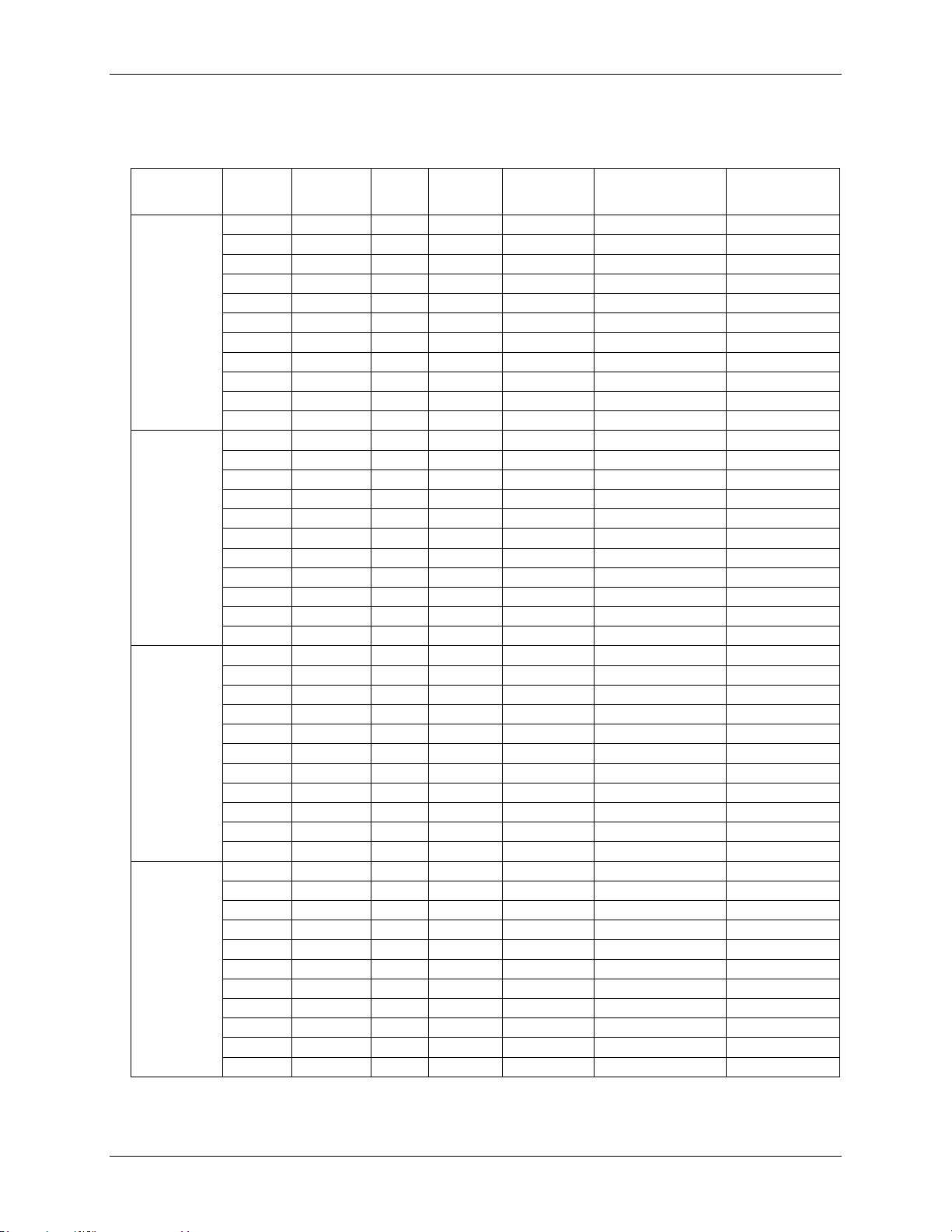
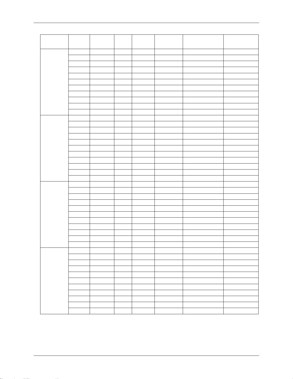
Analog input DC voltage measurement accuracy:
Table 12. DC Accuracy components and specifications. All values are (±)
35
Page 36
OMB-DAQ-2416 User's Guide Specifications
Range
A/D data
rate
Gain error
(% of
reading)
Offset
error
INL error
(% of
range)
Absolute
accuracy
Gain temperature
coefficient
(% reading/°C)
Offset
temperature
coefficient (µV/°C)
1.25 V
3750 S/s
0.0025
7 µV
0.0008
48.050 µV
0.0006
1
2000 S/s
0.0025
9 µV
0.0008
50.632 µV
0.0006
1
1000 S/s
0.0025
8 µV
0.0008
49.359 µV
0.0006
1
500 S/s
0.0025
8 µV
0.0008
49.709 µV
0.0006
1
100 S/s
0.0025
8 µV
0.0008
49.604 µV
0.0006
1
60 S/s
0.0025
8 µV
0.0008
49.417 µV
0.0006
1
50 S/s
0.0025
8 µV
0.0008
49.610 µV
0.0006
1
25 S/s
0.0025
8 µV
0.0008
49.584 µV
0.0006
1
10 S/s
0.0025
8 µV
0.0008
49.482 µV
0.0006
1
5 S/s
0.0025
8 µV
0.0008
49.489 µV
0.0006
1
2.5 S/s
0.0025
8 µV
0.0008
49.489 µV
0.0006
1
±0.625 V
3750 S/s
0.003
7 µV
0.0005
28.775 µV
0.0006
1
2000 S/s
0.003
7 µV
0.0005
28.679 µV
0.0006
1
1000 S/s
0.003
6 µV
0.0005
27.762 µV
0.0006
1
500 S/s
0.003
6 µV
0.0005
28.167 µV
0.0006
1
100 S/s
0.003
6 µV
0.0005
28.088 µV
0.0006
1
60 S/s
0.002
6 µV
0.0005
21.709 µV
0.0006
1
50 S/s
0.002
6 µV
0.0005
21.773 µV
0.0006
1
25 S/s
0.002
6 µV
0.0005
21.746 µV
0.0006
1
10 S/s
0.002
6 µV
0.0005
21.927 µV
0.0006
1
5 S/s
0.002
6 µV
0.0005
21.803 µV
0.0006
1
2.5 S/s
0.002
6 µV
0.0005
21.784 µV
0.0006
1
±0.3125 V
3750 S/s
0.005
7 µV
0.0006
24.500 µV
0.0006
1
2000 S/s
0.005
6 µV
0.0006
23.443 µV
0.0006
1
1000 S/s
0.005
6 µV
0.0006
23.086 µV
0.0006
1
500 S/s
0.005
6 µV
0.0006
23.094 µV
0.0006
1
100 S/s
0.005
6 µV
0.0006
23.084 µV
0.0006
1
60 S/s
0.005
6 µV
0.0006
23.288 µV
0.0006
1
50 S/s
0.005
6 µV
0.0006
23.232 µV
0.0006
1
25 S/s
0.005
6 µV
0.0006
23.191 µV
0.0006
1
10 S/s
0.005
6 µV
0.0006
23.125 µV
0.0006
1
5 S/s
0.005
6 µV
0.0006
23.182 µV
0.0006
1
2.5 S/s
0.005
6 µV
0.0006
23.127 µV
0.0006
1
±0.15625 V
3750 S/s
0.006
6 µV
0.0005
15.856 µV
0.0006
1
2000 S/s
0.006
6 µV
0.0005
15.793 µV
0.0006
1
1000 S/s
0.006
6 µV
0.0005
15.902 µV
0.0006
1
500 S/s
0.006
6 µV
0.0005
16.118 µV
0.0006
1
100 S/s
0.006
6 µV
0.0005
15.877 µV
0.0006
1
60 S/s
0.006
6 µV
0.0005
16.014 µV
0.0006
1
50 S/s
0.006
6 µV
0.0005
16.122 µV
0.0006
1
25 S/s
0.006
6 µV
0.0005
15.903 µV
0.0006
1
10 S/s
0.006
6 µV
0.0005
15.927 µV
0.0006
1
5 S/s
0.006
6 µV
0.0005
15.981 µV
0.0006
1
2.5 S/s
0.006
6 µV
0.0005
15.979 µV
0.0006
1
36
Page 37
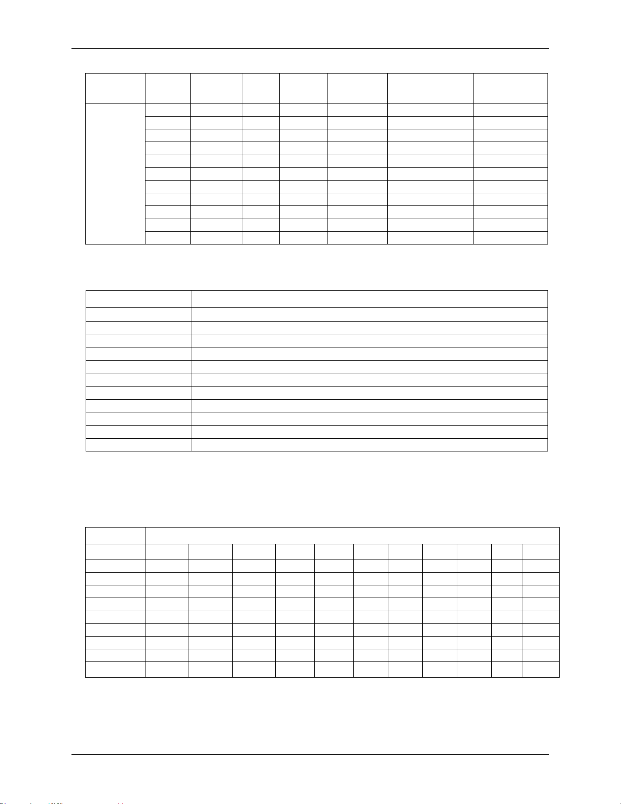
OMB-DAQ-2416 User's Guide Specifications
Range
A/D data
rate
Gain error
(% of
reading)
Offset
error
INL error
(% of
range)
Absolute
accuracy
Gain temperature
coefficient
(% reading/°C)
Offset
temperature
coefficient (µV/°C)
±0.078125 V
3750 S/s
0.035
6 µV
0.0009
33.547 µV
0.0006
1
2000 S/s
0.035
6 µV
0.0009
34.252 µV
0.0006
1
1000 S/s
0.035
6 µV
0.0009
33.696 µV
0.0006
1
500 S/s
0.035
6 µV
0.0009
34.002 µV
0.0006
1
100 S/s
0.035
6 µV
0.0009
34.005 µV
0.0006
1
60 S/s
0.035
6 µV
0.0009
33.866 µV
0.0006
1
50 S/s
0.035
6 µV
0.0009
34.026 µV
0.0006
1
25 S/s
0.035
6 µV
0.0009
33.933 µV
0.0006
1
10 S/s
0.035
6 µV
0.0009
33.937 µV
0.0006
1
5 S/s
0.035
6 µV
0.0009
33.969 µV
0.0006
1
2.5 S/s
0.035
6 µV
0.0009
33.934 µV
0.0006
1
A/D data rate
-3 dB Bandwidth (Hz)
3750 S/s
1615
2000 S/s
878
1000 S/s
441
500 S/s
221
100 S/s
44.2
60 S/s
26.5
50 S/s
22.1
25 S/s
11.1
10 S/s
4.42
5 S/s
2.21
2.5 S/s
1.1
A/D data rate
Range
3750 S/s
2000 S/s
1000 S/s
500 S/s
100 S/s
60 S/s
50 S/s
25 S/s
10 S/s
5 S/s
2.5 S/s
±20 V
230.31
186.92
126.84
100.14
57.22
57.22
49.59
47.58
23.84
23.84
14.31
±10 V
126.84
100.14
71.76
45.06
30.52
30.52
26.70
19.07
11.92
9.54
9.54
±5 V
56.74
47.56
34.21
25.87
16.21
14.31
14.31
14.30
5.96
4.77
4.77
±2.5 V
32.96
28.79
17.94
14.19
7.51
7.09
7.09
5.72
3.81
2.86
2.38
±1.25 V
18.57
17.52
13.83
9.30
5.48
5.48
5.01
3.81
3.34
3.34
2.86
±0.625 V
18.88
16.58
8.45
7.41
5.32
4.80
4.38
3.86
2.50
2.61
1.98
±0.3125 V
15.33
14.76
8.19
6.94
4.75
4.69
4.49
3.70
3.34
2.56
2.45
±0.156 25V
13.28
16.84
7.47
6.61
5.70
4.48
4.48
4.24
2.66
3.07
2.29
±0.078125 V
13.47
15.02
9.17
6.88
4.28
4.16
4.00
3.57
2.28
2.13
2.40
Input bandwidth
Table 13. input bandwidth
Noise performance
For the peak to peak noise distribution test, a differential input channel is connected to GND at the input
terminal block, and 50,000 samples are acquired at the maximum rate available at each setting.
Table 14. Peak to Peak noise performance specifications (µV)
37
Page 38
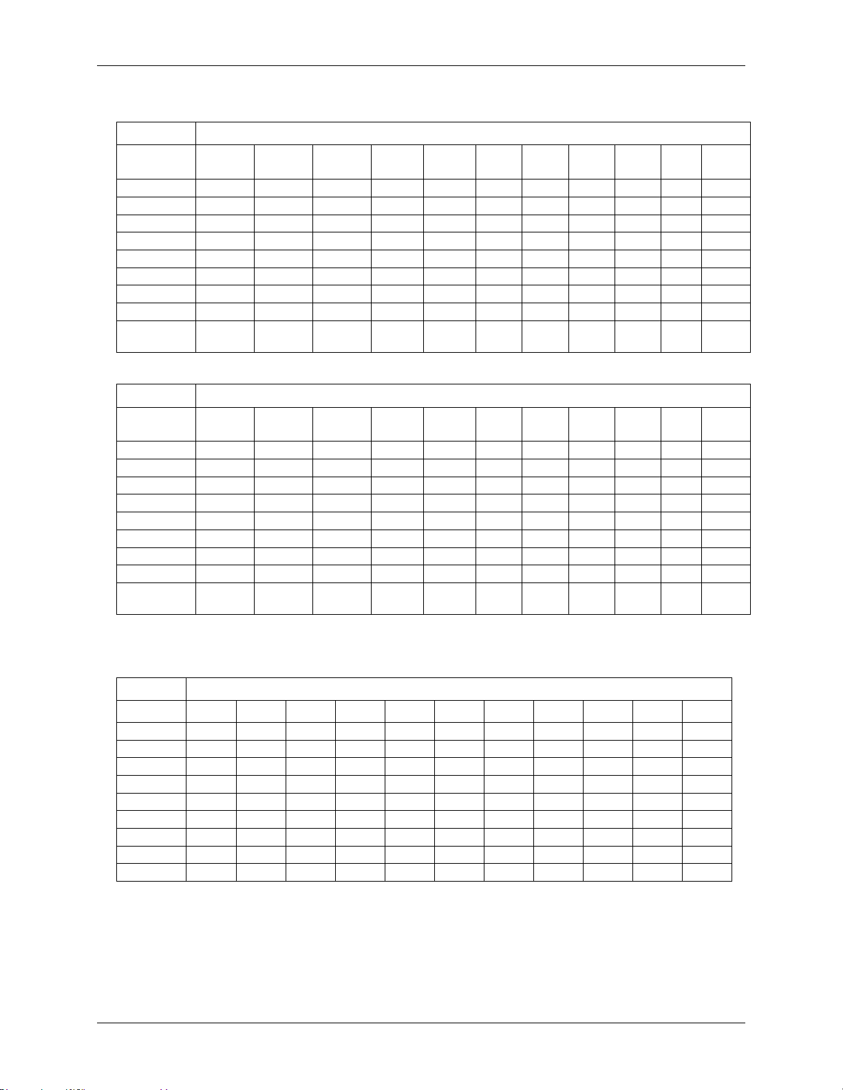
OMB-DAQ-2416 User's Guide Specifications
A/D data rate
Range
3750 S/
s
2000 S/
s
1000 S/
s
500 S/
s
100 S/
s
60 S/s 50 S/s 25 S/s 10 S/s 5 S/s 2.5 S/
s
±20 V
34.90
28.32
19.22
15.17
8.67
8.67
7.51
7.22
3.61
3.61
2.17
±10 V
19.22
15.17
10.87
6.83
4.62
4.62
4.05
2.89
1.81
1.44
1.44
±5 V
8.60
7.21
5.18
3.92
2.46
2.17
2.17
2.16
0.90
0.72
0.72
±2.5 V
4.99
4.36
2.72
2.15
1.14
1.07
1.07
0.87
0.58
0.43
0.36
±1.25 V
2.81
2.66
2.10
1.41
0.83
0.83
0.76
0.58
0.51
0.51
0.43
±0.625 V
2.86
2.51
1.28
1.12
0.81
0.73
0.66
0.58
0.38
0.40
0.30
±0.3125 V
2.32
2.24
1.24
1.05
0.72
0.71
0.68
0.56
0.51
0.39
0.37
±0.15625 V
2.01
2.55
1.13
1.00
0.86
0.68
0.68
0.64
0.40
0.47
0.35
±0.078125
V
2.04
2.28
1.39
1.04
0.65
0.63
0.60
0.54
0.35
0.32
0.36
A/D data rate
Range
3750 S/
s
2000 S/
s
1000 S/
s
500 S/
s
100 S/
s
60 S/s 50 S/s 25 S/s 10 S/s 5 S/s 2.5 S/
s
±20 V
17.4
17.7
18.2
18.6
19.4
19.4
19.6
19.6
20.6
20.6
21.4
±10 V
17.2
17.6
18.1
18.7
19.3
19.3
19.5
20.0
20.6
21.0
21.0
±5 V
17.4
17.6
18.1
18.5
19.2
19.4
19.4
19.4
20.6
21.0
21.0
±2.5 V
17.2
17.4
18.1
18.4
19.3
19.4
19.4
19.7
20.3
20.7
21.0
±1.25 V
17.0
17.1
17.4
18.0
18.8
18.8
18.9
19.3
19.5
19.5
19.7
±0.625 V
16.0
16.2
17.1
17.3
17.8
18.0
18.1
18.3
18.9
18.8
19.2
±0.3125 V
15.3
15.3
16.2
16.4
17.0
17.0
17.0
17.3
17.5
17.9
17.9
±0.15625 V
14.5
14.1
15.3
15.5
15.7
16.1
16.1
16.1
16.8
16.9
17.1
±0.078125
V
14.5
14.3
15.0
15.4
16.1
16.2
16.2
16.4
17.0
17.1
16.9
Accuracy
Range
3750 S/s
2000 S/s
1000 S/s
500 S/s
100 S/s
60 S/s
50 S/s
25 S/s
10 S/s
5 S/s
2.5 S/s
±20 V
0.0011%
0.0006%
0.0004%
0.0003%
0.0002%
0.0002%
0.0002%
0.0002%
0.0001%
0.0001%
0.0001%
±10 V
0.0010%
0.0008%
0.0005%
0.0004%
0.0002%
0.0002%
0.0003%
0.0002%
0.0001%
0.0001%
0.0001%
±5 V
0.0009%
0.0008%
0.0004%
0.0004%
0.0003%
0.0002%
0.0002%
0.0002%
0.0001%
0.0001%
0.0001%
±2.5 V
0.0010%
0.0007%
0.0008%
0.0004%
0.0003%
0.0002%
0.0002%
0.0002%
0.0002%
0.0001%
0.0001%
±1.25 V
0.0013%
0.0009%
0.0008%
0.0007%
0.0004%
0.0004%
0.0003%
0.0003%
0.0003%
0.0003%
0.0003%
±0.625 V
0.0022%
0.0016%
0.0011%
0.0011%
0.0007%
0.0007%
0.0005%
0.0005%
0.0004%
0.0005%
0.0003%
±0.3125 V
0.0031%
0.0031%
0.0020%
0.0017%
0.0015%
0.0012%
0.0010%
0.0010%
0.0012%
0.0009%
0.0009%
±0.15625 V
0.0056%
0.0062%
0.0048%
0.0037%
0.0032%
0.0025%
0.0024%
0.0021%
0.0019%
0.0022%
0.0016%
±0.078125 V
0.0114%
0.0123%
0.0076%
0.0070%
0.0041%
0.0051%
0.0046%
0.0036%
0.0032%
0.0030%
0.0034%
Table 15. RMS noise performance specifications (µVRMS)
Table 16. Noise-free resolution specifications (bits)
Channel switching error
Table 17. Step response accuracy specifications
Channel switching error is defined as the accuracy that can be expected after one conversion when switching
from a channel with a DC input at one extreme of full scale to another channel with a DC input at the other
extreme of full scale, expressed in terms of percentage of full scale value.
38
Page 39
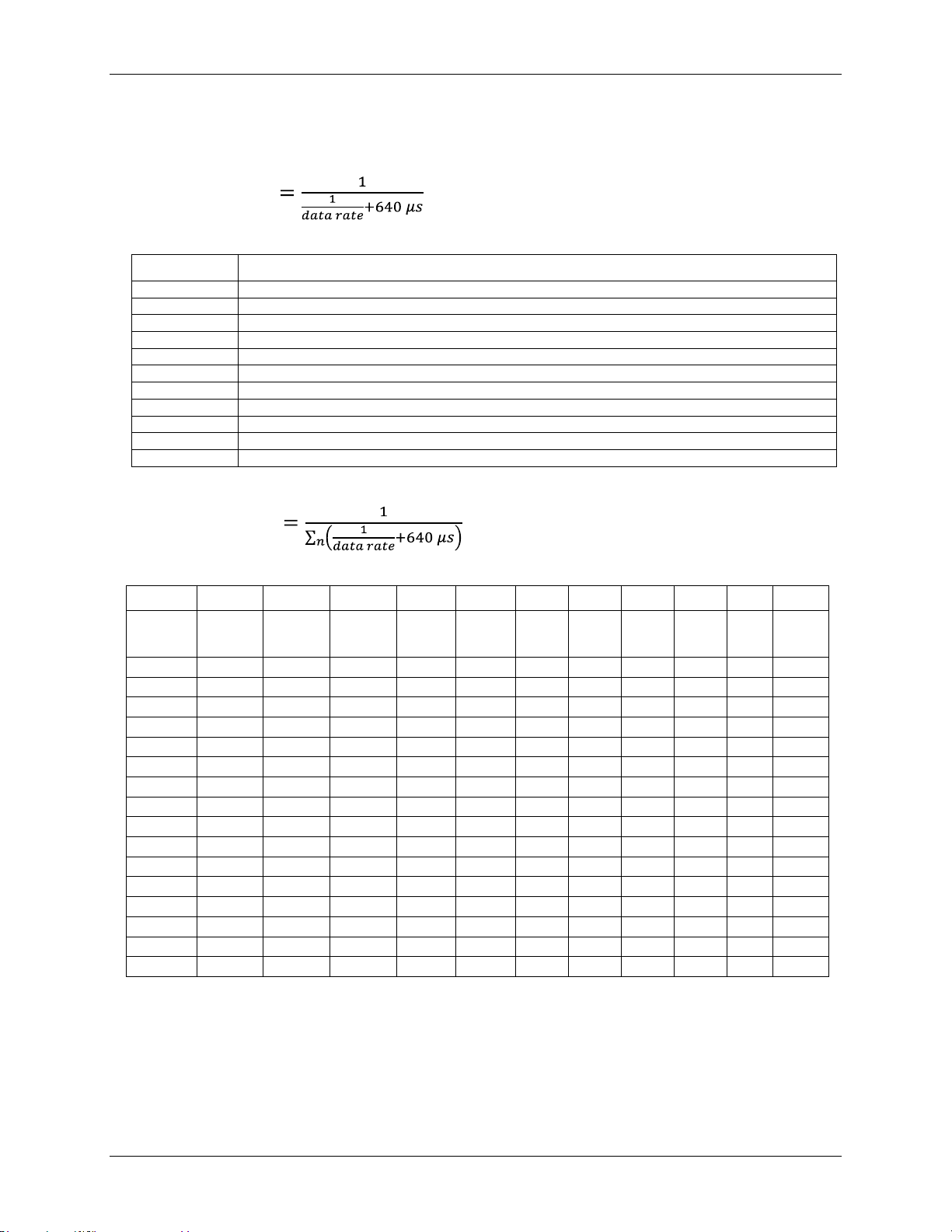
OMB-DAQ-2416 User's Guide Specifications
A/D data rate
Maximum throughput (Hz)
3750 S/s
1102.94
2000 S/s
877.19
1000 S/s
609.76
500 S/s
378.79
100 S/s
93.98
60 S/s
57.78
50 S/s
48.45
25 S/s
24.61
10 S/s
9.94
5 S/s
4.98
2.5 S/s
2.50
3750 S/s
2000 S/s
1000 S/s
500 S/s
100 S/s
60 S/s
50 S/s
25 S/s
10 S/s
5 S/s
2.5 S/s
Number
of input
channels
1
1102.94
877.19
609.76
378.79
93.98
57.78
48.45
24.61
9.94
4.98
2.50
2
551.47
438.60
304.88
189.39
46.99
28.89
24.22
12.30
4.97
2.49
1.25
3
367.65
292.40
203.25
126.26
31.33
19.26
16.15
8.20
3.31
1.66
0.83 4 275.74
219.30
152.44
94.70
23.50
14.45
12.11
6.15
2.48
1.25
0.62
5
220.59
175.44
121.95
75.76
18.80
11.56
9.69
4.92
1.99
1.00
0.50 6 183.82
146.20
101.63
63.13
15.66
9.63
8.07
4.10
1.66
0.83
0.42 7 157.56
125.31
87.11
54.11
13.43
8.25
6.92
3.52
1.42
0.71
0.36
8
137.87
109.65
76.22
47.35
11.75
7.22
6.06
3.08
1.24
0.62
0.31 9 122.55
97.47
67.75
42.09
10.44
6.42
5.38
2.73
1.10
0.55
0.28
10
110.29
87.72
60.98
37.88
9.40
5.78
4.84
2.46
0.99
0.50
0.25
11
100.27
79.74
55.43
34.44
8.54
5.25
4.40
2.24
0.90
0.45
0.23
12
91.91
73.10
50.81
31.57
7.83
4.82
4.04
2.05
0.83
0.42
0.21
13
84.84
67.48
46.90
29.14
7.23
4.44
3.73
1.89
0.76
0.38
0.19
14
78.78
62.66
43.55
27.06
6.71
4.13
3.46
1.76
0.71
0.36
0.18
15
73.53
58.48
40.65
25.25
6.27
3.85
3.23
1.64
0.66
0.33
0.17
16
68.93
54.82
38.11
23.67
5.87
3.61
3.03
1.54
0.62
0.31
0.16
Throughput rate
The single channel throughput rate is calculated using this formula:
Maximum throughput
Table 18. Single channel throughput rate specifications
The multiple-channel throughput rate is calculated using this formula:
Maximum throughput where n is the number of channels
Table 19. Multiple-channel throughput rate specifications (Hz)
39
Page 40
OMB-DAQ-2416 User's Guide Specifications
Parameter
Specifications
Recommended warm-up time
45 minutes minimum
Calibration
Firmware calibration
Calibration interval
1 year
Calibration reference
+10.000 V, ±5 mV maximum. Actual measured values stored in EEPROM
Tempco: 5 ppm/°C maximum
Long term stability: 30 ppm/1000 hours
Number of I/O
8 channels
Configuration
Each DIO bit can be independently read from (DIN) or written to (DOUT).
The DIN bits can be read at any time whether the DOUT is active or tri-stated.
Input voltage range
0 to +15 V
Input type
CMOS (Schmitt trigger)
Input characteristics
47 kΩ pull-up/pull-down resistor, 28 kΩ series resistor
Maximum input voltage range
0 to +20 V maximum (power on/off, relative to DGND pins 93 and 94)
Pull-up/pull-down
configuration
All pins pulled up to +5 V via individual 47 kΩ resistors (the JP1 shorting block
default position is pins 1 and 2).
Pull down capability is available by placing the JP1 shorting block across pins 2 and 3.
Transfer rate (software paced)
500 port reads or single bit reads per second typical.
Input high voltage
1.3 V minimum, 2.2 V maximum
Input low voltage
1.5 V maximum, 0.6 V minimum
Schmitt trigger hysteresis
0.4 V minimum, 1.2 V maximum
Number of I/O
8 channels
Configuration
Each DIO bit can be independently read from (DIN) or written to (DOUT).
The DIN bits may be read at any time whether the DOUT is active or tri-stated
Output characteristics
47k Ω pull-up, open drain (DMOS transistor)
Pull-up configuration
All pins pulled up to +5 V via individual 47 kΩ resistors (the JP1 shorting block
default position is pins 1 and 2).
Transfer rate (software paced)
Digital output – 500 port writes or single-bit writes per second typical.
Output voltage range
0 to +5 V (no external pull up resistor, internal 47 kΩ pull-up resistors connected to
+5V by default)
0 to +15 V maximum (Note 5)
Drain to source breakdown
voltage
+50 V minimum
Off state leakage current
(Note 6)
0.1 µA
Sink current capability
150 mA maximum (continuous) per output pin,
150 mA maximum (continuous) for all eight channels
DMOS transistor on-resistance
(drain to source)
4 Ω
Analog input calibration
Table 20. Analog input calibration specifications
Digital input/output
Table 21. Digital input specifications
Note 2: DGND pins (pins 93, 94) are recommended for use with digital input and digital output pins. The
DGND and GND pins are common and are isolated from earth ground.
Table 22. Digital output specifications
Note 3: Each DMOS transistor’s source pin is internally connected to GND.
Note 4: DGND pins (pins 93, 94) are recommended for use with digital input and digital output pins. The
DGND and GND pins are common and are isolated from earth ground.
40
Page 41
OMB-DAQ-2416 User's Guide Specifications
Parameter
Conditions
Specification
Pin name
CTR0, CTR1
Number of channels
2 channels
Resolution
32-bits
Counter type
Event counter
Input type
Schmitt trigger, rising edge triggered
Input source
CTR0 (pin 43)
CTR1 (pin 45)
Counter read/writes rates
(software paced)
Counter read
System dependent, 500 reads per second.
Counter write
System dependent, 500 reads per second.
Input characteristics
Each CTRx input pin
562 KΩ pull-up resistor to +5V, 10 kΩ series
resistor
Input voltage range
±15 V maximum
Maximum input voltage range
CTR0,CTR1 relative to GND and
DGND (pins
18,36,39,42,44,46,66,81,84,93,94)
±20 V maximum (power on/off)
Input high voltage
1.3 V minimum, 2.2 V maximum
Input low voltage
1.5 V maximum, 0.6 V minimum
Schmitt trigger hysteresis
0.4 V minimum, 1.2 V maximum
Input bandwidth (-3 dB)
1 MHz
Input capacitance
25 pf
Input leakage current
±120 nA
Input frequency
1 MHz maximum
High pulse width
500 ns, minimum
Low pulse width
500 ns, minimum
EEPROM
4096 bytes isolated micro reserved for sensor configuration
256 bytes USB micro for external application use
Type
One high-performance 8-bit RISC microcontroller with USB interface (non-isolated)
One high-performance 16-bit RISC microcontroller for measurements (isolated)
Note 5: The external pull-up is connected to the digital output bit through an external pull-up resistor. Adding
an external pull-up resistor connects it in parallel with the internal 47k Ω pull-up resistor of that
particular digital input/output bit. Careful consideration should be made when considering the external
pull-up resistor value and the resultant pull-up voltage produced at the load.
Note 6: Does not include the additional leakage current contribution that may occur when using an external
pull-up resistor.
Counter
Table 23. CTR specifications
Note 7: The DGND and GND pins (pins 18,36,39,42,44,46,66,81,84,93,94) are common and are isolated from
earth ground.
Memory
Table 24. Memory specifications
Microcontroller
Table 25. Microcontroller specifications
41
Page 42
OMB-DAQ-2416 User's Guide Specifications
Parameter
Conditions
Specification
Supply current (Note 8)
Quiescent current
330 mA
External power input (Note 9)
+5 V, ±5%
External power supply
Omega p/n OMB-DAQ-2416-ADAP
(included)
+5 VDC, 10 W, 5% regulation
Voltage supervisor limits
4.5 V > V
ext
or V
ext
> 5.5 V
PWR LED = Off; (power fault)
4.5 V < V
ext
< 5.5 V
PWR LED = On
+5V user output voltage range
Available at terminal block pin 35
4.9 V minimum to 5.1 V maximum
User +5V user output current
Available at terminal block pin 35
10 mA maximum
Isolation
Measurement system to PC
500 VDC minimum
Parameter
Conditions
Specification
Output voltage
+5 V, ±5%
Output wattage
10 watts
Power jack configuration
Two conductor
Power jack barrel diameter
6.3mm
Power jack pin diameter
2.0mm
Power jack polarity
Center positive
USB device type
USB 2.0 (full-speed)
Device compatibility
USB 1.1, USB 2.0
USB cable type
A-B cable, UL type AWM 2527 or equivalent. (minimum 24 AWG VBUS/GND,
minimum 28 AWG D+/D–)
USB cable length
5 meters maximum
Operating temperature range
0 to 50° C maximum
Storage temperature range
-40 to 85 ° C maximum
Humidity
0 to 90% non-condensing maximum
Power
Table 26. Power specifications
Note 8: This is the total quiescent current requirement for the OMB-DAQ-2416 which includes up to 10 mA
for the status LED. This does not include any potential loading of the digital I/O bits or the +5V user
terminal.
Note 9: This specification applies to the actual voltage level at the input to the external power connector of the
OMB-DAQ-2416.
Table 27. AC power requirements
USB specifications
Table 28. USB specifications
Environmental
The environmental specifications listed in Table 29 apply only to the OMB-DAQ-2416 and not to the external
power supply.
Table 29. Environmental specifications
42
Page 43
OMB-DAQ-2416 User's Guide Specifications
Dimensions
245 mm (L) x 146 mm (W) x 50mm (H)
User connection length
5 meters maximum
Connector type
Detachable screw terminal
Wire gauge range
16 AWG to 30 AWG
Mechanical
Table 30. Mechanical specifications
Screw terminal connector type and pin-out
Table 31. Screw terminal connector specifications
Screw terminal pin out
For additional channel configurations when using the optional AI-EXP expansion device, refer to the "Optional
OMB-AI-EXP32 expansion module" section on page 46.
43
Page 44
OMB-DAQ-2416 User's Guide Specifications
Pin
Signal name
Pin description
Pin
Signal name
Pin description
1
NC
No connect
49
NC
No connect
2
CH0H
Channel 0 HI
50
CH15L
Channel 15 LO
3
CH0L
Channel 0 LO
51
CH15H
Channel 15 HI
4
NC
No connect
52
IC14
No connect
5
IC0
No connect
53
4WC14
No connect
6
CH1H
Channel 1 HI
54
CH14L
Channel 14 LO
7
CH1L
Channel 1 LO
55
CH14H
Channel 14 HI
8
4WC1
No connect
56
IC13
No connect
9
IC1
No connect
57
4WC13
No connect
10
CH2H
Channel 2 HI
58
CH13L
Channel 13 LO
11
CH2L
Channel 2 LO
59
CH13H
Channel 13 HI
12
4WC2
No connect
60
IC12
No connect
13
IC2
No connect
61
4WC12
No connect
14
CH3H
Channel 3 HI
62
CH12L
Channel 12 LO
15
CH3L
Channel 3 LO
63
CH12H
Channel 12 HI
16
4WC3
No connect
64
IC11
No connect
17
IC3
No connect
65
4WC11
No connect
18
GND
Analog ground
66
GND
Analog ground
19
CH4H
Channel 4 HI
67
CH11L
Channel 11 LO
20
CH4L
Channel 4 LO
68
CH11H
Channel 11 HI
21
4WC4
No connect
69
IC10
No connect
22
IC4
No connect
70
4WC10
No connect
23
CH5H
Channel 5 HI
71
CH10L
Channel 10 LO
24
CH5L
Channel 5 LO
72
CH10H
Channel 10 HI
25
4WC5
No connect
73
IC9
No connect
26
IC5
No connect
74
4WC9
No connect
27
CH6H
Channel 6 HI
75
CH9L
Channel 9 LO
28
CH6L
Channel 6 LO
76
CH9H
Channel 9 HI
29
4WC6
No connect
77
IC8
No connect
30
IC6
No connect
78
4WC8
No connect
31
CH7H
Channel 7 HI
79
CH8L
Channel 8 LO
32
CH7L
Channel 7 LO
80
CH8H
Channel 8 HI
33
4WC7
No connect
81
GND
Analog ground
34
IC7
No connect
82
NC
No connect
35
+5V
+5V output
83
NC
No connect
36
GND
Analog ground
84
GND
Analog ground
37
NC
No connect
85
DIO7
Digital input/output
38
NC
No connect
86
DIO6
Digital input/output
39
GND
Analog ground
87
DIO5
Digital input/output
40
NC
No connect
88
DIO4
Digital input/output
41
NC
No connect
89
DIO3
Digital input/output
42
GND
Analog ground
90
DIO2
Digital input/output
43
CTR0
Counter input Ch0
91
DIO1
Digital input/output
44
GND
Analog ground
92
DIO0
Digital input/output
45
CTR1
Counter input Ch1
93
DGND
Digital I/O ground
46
GND
Analog ground
94
DGND
Digital I/O ground
47
NC
No connect
95
NC
No connect
48
NC
No connect
96
NC
No connect
Table 32. 16-channel differential mode pin out
Do not connect to terminal block pins labeled "NC."
44
Page 45
OMB-DAQ-2416 User's Guide Specifications
Pin
Signal name
Pin description
Pin
Signal name
Pin description
1
NC
No connect
49
NC
No connect
2
CH0H
Channel 0
50
CH15L
Channel 31
3
CH0L
Channel 16
51
CH15H
Channel 15
4
NC
No connect
52
IC14
No connect
5
IC0
No connect
53
4WC14
No connect
6
CH1H
Channel 1
54
CH14L
Channel 30
7
CH1L
Channel 17
55
CH14H
Channel 14
8
4WC1
No connect
56
IC13
No connect
9
IC1
No connect
57
4WC13
No connect
10
CH2H
Channel 2
58
CH13L
Channel 29
11
CH2L
Channel 18
59
CH13H
Channel 13
12
4WC2
No connect
60
IC12
No connect
13
IC2
No connect
61
4WC12
No connect
14
CH3H
Channel 3
62
CH12L
Channel 28
15
CH3L
Channel 19
63
CH12H
Channel 12
16
4WC3
No connect
64
IC11
No connect
17
IC3
No connect
65
4WC11
No connect
18
GND
Analog ground
66
GND
Analog ground
19
CH4H
Channel 4
67
CH11L
Channel 27
20
CH4L
Channel 20
68
CH11H
Channel 11
21
4WC4
No connect
69
IC10
No connect
22
IC4
No connect
70
4WC10
No connect
23
CH5H
Channel 5
71
CH10L
Channel 26
24
CH5L
Channel 21
72
CH10H
Channel 10
25
4WC5
No connect
73
IC9
No connect
26
IC5
No connect
74
4WC9
No connect
27
CH6H
Channel 6
75
CH9L
Channel 25
28
CH6L
Channel 22
76
CH9H
Channel 9
29
4WC6
No connect
77
IC8
No connect
30
IC6
No connect
78
4WC8
No connect
31
CH7H
Channel 7
79
CH8L
Channel 24
32
CH7L
Channel 23
80
CH8H
Channel 8
33
4WC7
No connect
81
GND
Analog ground
34
IC7
No connect
82
NC
No connect
35
+5V
+5V output
83
NC
No connect
36
GND
Analog ground
84
GND
Analog ground
37
NC
No connect
85
DIO7
Digital input/output
38
NC
No connect
86
DIO6
Digital input/output
39
GND
Analog ground
87
DIO5
Digital input/output
40
NC
No connect
88
DIO4
Digital input/output
41
NC
No connect
89
DIO3
Digital input/output
42
GND
Analog ground
90
DIO2
Digital input/output
43
CTR0
Counter input Ch0
91
DIO1
Digital input/output
44
GND
Analog ground
92
DIO0
Digital input/output
45
CTR1
Counter input Ch1
93
DGND
Digital I/O ground
46
GND
Analog ground
94
DGND
Digital I/O ground
47
NC
No connect
95
NC
No connect
48
NC
No connect
96
NC
No connect
Table 33. 32-channel single-ended mode pin out
Do not connect to terminal block pins labeled "NC."
45
Page 46
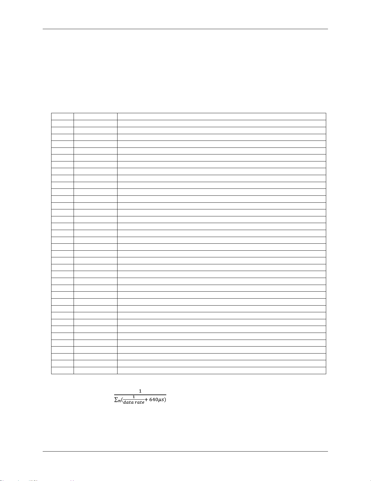
OMB-DAQ-2416 User's Guide Specifications
Pin
Signal name
Pin description
1
GND
Analog ground
2
NC
No connect
3
GND
Analog ground
4
NC
No connect
5
GND
Analog ground
6
VCC
+12 V power
7
NC
No connect
8
NC
No connect
9
IM_A2
I/O control signal
10
IM_A1
I/O control signal
11
IM_A0
I/O control signal
12
IMEN10
I/O control signal
13
IMEN9
I/O control signal
14
IMEN8
I/O control signal
15
IMEN7
I/O control signal
16
DIO_LOAD2
I/O control signal
17
DIO_LOAD1
I/O control signal
18
NC
No connect
19
NC
No connect
20
+3.3V_ISO
+3.3 V power
21
GND
Analog ground
22
+5 VA
+5 V analog power
23
+20.5V
+20.5 V power
24
GND
Analog ground
25
-20.5V
-20.5 V power
26
VDD_ISO
+5 V digital power
27
EXTDIO_INT
I/O control signal
28
CM_A3
I/O control signal
29
SM_A1
I/O control signal
30
SM_AO
I/O control signal
31
CM_A2
I/O control signal
32
SCL
Serial I/O control signal
33
SDA
Serial I/O control signal
34
MOSI
Serial I/O control signal
35
SCK
Serial I/O control signal
36
NC
No connect
37
NC
No connect
Optional OMB-AI-EXP32 expansion module
Use the OMB-AI-EXP32 (sold separately) for applications that need additional analog/thermocouple input and
digital I/O channels. See the Omega Engineering web site for product details.
The OMB-AI-EXP32 expansion port is intended to interface with a OMB-DAQ-2416 series product. Do not try
to use any of the expansion port pins for any other purpose.
Table 34. OMB-AI-EXP32 37-pin connector pin out
Do not connect to terminal block pins labeled "NC."
The multiple-channel throughput rate calculation is based on the following formula:
Maximum throughput = , where n is the number of channels
46
Page 47
OMB-DAQ-2416 User's Guide Specifications
3750 S/s
2000 S/s
1000 S/s
500 S/s
100 S/s
60 S/s
50 S/s
25 S/s
10 S/s
5 S/s
2.5 S/s
Number of
input
channels
1
1102.94
877.19
609.76
378.79
93.98
57.78
48.45
24.61
9.94
4.98
2.50 2 551.47
438.60
304.88
189.39
46.99
28.89
24.22
12.30
4.97
2.49
1.25 3 367.65
292.40
203.25
126.26
31.33
19.26
16.15
8.20
3.31
1.66
0.83 4 275.74
219.30
152.44
94.70
23.50
14.45
12.11
6.15
2.48
1.25
0.62 5 220.59
175.44
121.95
75.76
18.80
11.56
9.69
4.92
1.99
1.00
0.50 6 183.82
146.20
101.63
63.13
15.66
9.63
8.07
4.10
1.66
0.83
0.42 7 157.56
125.31
87.11
54.11
13.43
8.25
6.92
3.52
1.42
0.71
0.36 8 137.87
109.65
76.22
47.35
11.75
7.22
6.06
3.08
1.24
0.62
0.31 9 122.55
97.47
67.75
42.09
10.44
6.42
5.38
2.73
1.10
0.55
0.28
10
110.29
87.72
60.98
37.88
9.40
5.78
4.84
2.46
0.99
0.50
0.25
11
100.27
79.74
55.43
34.44
8.54
5.25
4.40
2.24
0.90
0.45
0.23
12
91.91
73.10
50.81
31.57
7.83
4.82
4.04
2.05
0.83
0.42
0.21
13
84.84
67.48
46.90
29.14
7.23
4.44
3.73
1.89
0.76
0.38
0.19
14
78.78
62.66
43.55
27.06
6.71
4.13
3.46
1.76
0.71
0.36
0.18
15
73.53
58.48
40.65
25.25
6.27
3.85
3.23
1.64
0.66
0.33
0.17
16
68.93
54.82
38.11
23.67
5.87
3.61
3.03
1.54
0.62
0.31
0.16
17
64.88
51.60
35.87
22.28
5.53
3.40
2.85
1.45
0.58
0.29
0.15
18
61.27
48.73
33.88
21.04
5.22
3.21
2.69
1.37
0.55
0.28
0.14
19
58.05
46.17
32.09
19.94
4.95
3.04
2.55
1.30
0.52
0.26
0.13
20
55.15
43.86
30.49
18.94
4.70
2.89
2.42
1.23
0.50
0.25
0.12
21
52.52
41.77
29.04
18.04
4.48
2.75
2.31
1.17
0.47
0.24
0.12
22
50.13
39.87
27.72
17.22
4.27
2.63
2.20
1.12
0.45
0.23
0.11
23
47.95
38.14
26.51
16.47
4.09
2.51
2.11
1.07
0.43
0.22
0.11
24
45.96
36.55
25.41
15.78
3.92
2.41
2.02
1.03
0.41
0.21
0.10
25
44.12
35.09
24.39
15.15
3.76
2.31
1.94
0.98
0.40
0.20
0.10
26
42.42
33.74
23.45
14.57
3.61
2.22
1.86
0.95
0.38
0.19
0.10
27
40.85
32.49
22.58
14.03
3.48
2.14
1.79
0.91
0.37
0.18
0.09
28
39.39
31.33
21.78
13.53
3.36
2.06
1.73
0.88
0.35
0.18
0.09
29
38.03
30.25
21.03
13.06
3.24
1.99
1.67
0.85
0.34
0.17
0.09
30
36.76
29.24
20.33
12.63
3.13
1.93
1.61
0.82
0.33
0.17
0.08
31
35.58
28.30
19.67
12.22
3.03
1.86
1.56
0.79
0.32
0.16
0.08
32
34.47
27.41
19.05
11.84
2.94
1.81
1.51
0.77
0.31
0.16
0.08
Table 35. Multiple-channel throughput rate specifications (Hz),
OMB-DAQ-2416 and optional OMB-AI-EXP32 expansion module
47
Page 48
OMB-DAQ-2416 User's Guide Specifications
Pin
Signal name
Pin description
Pin
Signal name
Pin description
1
CH16H
Channel 16 HI
49
CH31L
Channel 31 LO
2
CH16L
Channel 16 LO
50
CH31H
Channel 31 HI
3
CH17H
Channel 17 HI
51
CH30L
Channel 30 LO
4
CH17L
Channel 17 LO
52
CH30H
Channel 30 HI
5
CH18H
Channel 18 HI
53
CH29L
Channel 29 LO
6
CH18L
Channel 18 LO
54
CH29H
Channel 29 HI
7
CH19H
Channel 19 HI
55
CH28L
Channel 28 LO
8
CH19L
Channel 19 LO
56
CH28H
Channel 28 HI
9
CH20H
Channel 20 HI
57
CH27L
Channel 27 LO
10
CH20L
Channel 20 LO
58
CH27H
Channel 27 HI
11
CH21H
Channel 21 HI
59
CH26L
Channel 26 LO
12
CH21L
Channel 21 LO
60
CH26H
Channel 26 HI
13
CH22H
Channel 22 HI
61
CH25L
Channel 25 LO
14
CH22L
Channel 22 LO
62
CH25H
Channel 25 HI
15
CH23H
Channel 23 HI
63
CH24L
Channel 24 LO
16
CH23L
Channel 23 LO
64
CH24H
Channel 24 HI
17
GND
Analog ground
65
GND
Analog ground
18
GND
Analog ground
66
GND
Analog ground
19
+5VUSER
+5V output
67
NC
No connect
20
NC
No connect
68
NC
No connect
21
DIO8
Digital input/output
69
DIO23
Digital input/output
22
DIO9
Digital input/output
70
DIO22
Digital input/output
23
DIO10
Digital input/output
71
DIO21
Digital input/output
24
DIO11
Digital input/output
72
DIO20
Digital input/output
25
DIO12
Digital input/output
73
DIO19
Digital input/output
26
DIO13
Digital input/output
74
DIO18
Digital input/output
27
DIO14
Digital input/output
75
DIO17
Digital input/output
28
DIO15
Digital input/output
76
DIO16
Digital input/output
29
DGND
Digital ground
77
DGND
Digital ground
30
DGND
Digital ground
78
DGND
Digital ground
31
NC
No connect
79
NC
No connect
32
NC
No connect
80
NC
No connect
OMB-AI-EXP32 screw terminal pin out
Table 36. 32-channel differential mode pin out
Do not connect to terminal block pins labeled "NC."
48
Page 49
OMB-DAQ-2416 User's Guide Specifications
Pin
Signal name
Pin description
Pin
Signal name
Pin description
1
CH16H
Channel 16
33
CH31L
Channel 63
2
CH16L
Channel 48
34
CH31H
Channel 31
3
CH17H
Channel 17
35
CH30L
Channel 62
4
CH17L
Channel 49
36
CH30H
Channel 30
5
CH18H
Channel 18
37
CH29L
Channel 61
6
CH18L
Channel 50
38
CH29H
Channel 29
7
CH19H
Channel 19
39
CH28L
Channel 60
8
CH19L
Channel 51
40
CH28H
Channel 28
9
CH20H
Channel 20
41
CH27L
Channel 59
10
CH20L
Channel 52
42
CH27H
Channel 27
11
CH21H
Channel 21
43
CH26L
Channel 58
12
CH21L
Channel 53
44
CH26H
Channel 26
13
CH22H
Channel 22
45
CH25L
Channel 57
14
CH22L
Channel 54
46
CH25H
Channel 25
15
CH23H
Channel 23
47
CH24L
Channel 56
16
CH23L
Channel 55
48
CH24H
Channel 24
17
GND
Analog ground
49
GND
Analog ground
18
GND
Analog ground
50
GND
Analog ground
19
+5VUSER
+5V output
51
NC
No connect
20
NC
No connect
52
NC
No connect
21
DIO8
Digital input/output
69
DIO23
Digital input/output
22
DIO9
Digital input/output
70
DIO22
Digital input/output
23
DIO10
Digital input/output
71
DIO21
Digital input/output
24
DIO11
Digital input/output
72
DIO20
Digital input/output
25
DIO12
Digital input/output
73
DIO19
Digital input/output
26
DIO13
Digital input/output
74
DIO18
Digital input/output
27
DIO14
Digital input/output
75
DIO17
Digital input/output
28
DIO15
Digital input/output
76
DIO16
Digital input/output
29
DGND
Digital ground
61
DGND
Digital ground
30
DGND
Digital ground
62
DGND
Digital ground
31
NC
No connect
63
NC
No connect
32
NC
No connect
64
NC
No connect
Table 37. 32-channel single-ended mode pin out
Do not connect to terminal block pins labeled "NC."
49
Page 50
OMB-DAQ-2416 User's Guide Specifications
Pin
Signal name
Pin description
Pin
Signal name
Pin description
1
NC
No connect
49
NC
No connect
2
CH0H
Channel 0
50
CH15L
Channel 47
3
CH0L
Channel 32
51
CH15H
Channel 15
4
NC
No connect
52
IC14
No connect
5
IC0
No connect
53
4WC14
No connect
6
CH1H
Channel 1
54
CH14L
Channel 46
7
CH1L
Channel 33
55
CH14H
Channel 14
8
4WC1
No connect
56
IC13
No connect
9
IC1
No connect
57
4WC13
No connect
10
CH2H
Channel 2
58
CH13L
Channel 45
11
CH2L
Channel 34
59
CH13H
Channel 13
12
4WC2
No connect
60
IC12
No connect
13
IC2
No connect
61
4WC12
No connect
14
CH3H
Channel 3
62
CH12L
Channel 44
15
CH3L
Channel 35
63
CH12H
Channel 12
16
4WC3
No connect
64
IC11
No connect
17
IC3
No connect
65
4WC11
No connect
18
GND
Analog ground
66
GND
Analog ground
19
CH4H
Channel 4
67
CH11L
Channel 43
20
CH4L
Channel 36
68
CH11H
Channel 11
21
4WC4
No connect
69
IC10
No connect
22
IC4
No connect
70
4WC10
No connect
23
CH5H
Channel 5
71
CH10L
Channel 42
24
CH5L
Channel 37
72
CH10H
Channel 10
25
4WC5
No connect
73
IC9
No connect
26
IC5
No connect
74
4WC9
No connect
27
CH6H
Channel 6
75
CH9L
Channel 41
28
CH6L
Channel 38
76
CH9H
Channel 9
29
4WC6
No connect
77
IC8
No connect
30
IC6
No connect
78
4WC8
No connect
31
CH7H
Channel 7
79
CH8L
Channel 40
32
CH7L
Channel 39
80
CH8H
Channel 8
33
4WC7
No connect
81
GND
Analog ground
34
IC7
No connect
82
NC
No connect
35
+5V
+5V output
83
NC
No connect
36
GND
Analog ground
84
GND
Analog ground
37
NC
No connect
85
DIO7
Digital input/output
38
NC
No connect
86
DIO6
Digital input/output
39
GND
Analog ground
87
DIO5
Digital input/output
40
NC
No connect
88
DIO4
Digital input/output
41
NC
No connect
89
DIO3
Digital input/output
42
GND
Analog ground
90
DIO2
Digital input/output
43
CTR0
Counter input Ch0
91
DIO1
Digital input/output
44
GND
Analog ground
92
DIO0
Digital input/output
45
CTR1
Counter input Ch1
93
DGND
Digital I/O ground
46
GND
Analog ground
94
DGND
Digital I/O ground
47
NC
No connect
95
NC
No connect
48
NC
No connect
96
NC
No connect
OMB-DAQ-2416 screw terminal pin out (with OMB-AI-EXP32 attached)
Table 38. OMB-DAQ-2416 single-ended mode pin out with OMB-AI-EXP32 connected
Do not connect to terminal block pins labeled "NC."
50
Page 51
Page 52
52
 Loading...