

Page 1

OAL-100 INSTALATION INSTRUCTIONS
WARNING! AVOID ELECTRICAL SHOCK
DISCONNECT POWER DURING INSTALLATION
PLEASE READ ALL INSTRUCTIONS BEFORE INSTALLATION
POWER SUPPLY REQUIRED 115+/- 5VAC-60 HZ 0.4AMPS
CONTROL BOARD POWER SUPPLY 16VDC
CONTROL BOARD TO BE GROUNDED
KEEP FINGERS & CLOTHING CLEAR OF ALL MOVING PARTS
ADJUSTMENTS TO BE PERFORMED BY APPROVED TECHNICIAN ONLY
ALTERATION TO ANY COMPONENTS IS PROHIBITED
REMOVE ANY MECHANICAL DEVICES OR LOCKS THAT INTERFERE WITH
THE OPERATION OF THE DOOR, (OTHER THAN PARTS INTEGRATED WITH
THE OPERATOR SYSTEM).
OPERATOR TO BE INSTALLED 8 FEET MINIMUM ABOVE GROUND IF THERE
ARE ANY EXPOSED MOVING PARTS
O M E G A A U T O M A T I C S 2 0 1 8
V 2 . 0
Page 2

Mounting the Operator:
Fasteners
120 VAC
Notes:
-Ensure that door swings and latches easily before attempting to add operator
-Remove cover from operator
-Operator to wall mounting must be very strong!
-All loads from high winds & other overloads will be transferred thru the fasteners to the wall
-Use appropriate fasteners and anchors for the type of wall being mounted to
-Mounting to drywall construction requires plwood backer inside the wall to attach operator
-If the door framing is proud of the wall, place a filler allowing the operator to sit flat & plumb
-Attach to vertical jamb tubes when mounting to curtain wall
filler
drill & fasten
thru
slots
plywood
back
er
board
operator
back
plate
drywall mounting curtain wall mounting
fasten to jamb tubes
fasten along header
O M E G A A U T O M A T I C S 2 0 1 8
V 2 . 0
Page 3

Push Arm:
- Requires cutting of the round bar
- Mount block 14 1/2" from hinge
- Install arm onto spindle as per diagram
- Close door and place round shaft beside tube
- Cut the round rod 2" past last grub screw
- Rod can be slid in out for final adjustment
- Slide rod into position and tighten grub screws
- Remove complete arm from the shaft
- Use jumper wire to "hold open" the motor
- Position the door in full open position
- Typically 90 to 105 degrees
- Reinstall arm onto shaft and tighten screw
(3/16")
- Install safety washer & screw
- Remove jumper wire & adjust magnets
- See "setting the magnets"
shaft
screw
high mount
safety washer
screw
14 1/2"
low mount
1 1/2"
4 1/8"
2 1/2"
tube
rod
O M E G A A U T O M A T I C S 2 0 1 8
block
V 2 . 0
Page 4

Pull Arm:
-Install roller onto arm (5/32" allen)
-Install jumper wire to "hold open" motor
-Slide arm onto shaft, typically 90 to 105
degrees & tighten pinch screw
-Remove jumper wire so roller contacts door
-Roller needs to be vertically centered in track
-Fasten track to door (see diagram)
-Place end caps on the track
-Install safety washer & screw
-Adjust magnets; see "setting the magnets"
1 3/4"
shaft
center wheel
screw
safety washer
1 1/2" minimum
arm
roller
track
fasten pull track to door
fasten pull track
to
door
O M E G A A U T O M A T I C S 2 0 1 8
V 2 . 0
Page 5

Wiring:
control board
to motor
to magnet
switches
120 VAC
to be connected by
Notes:
- Run 120 VAC power lines as per building code
- Run low voltage wires to/from any input/outputs such as buttons or strikes
- Power is to be connected by authorized electrician to local codes
- Once power is hooked up the unit can be test cycled by pressing "ACT"
- Ensure that operator is working properly before adding inputs/outputs
- Magnets must be properly positioned in order for operator to function (see setting the magnets)
- Full open position is limited by an internal stop not the magnets
- The magnets
- Magnets can be adjusted to change the point where the door slows for back check and latch
- Use a jumper wire to hold operator in full open position to attach arm.
- Have certified Electrician to do installation ONLY!
- Have certified Electrician to hook the wire into the power side properly.
- Add the L1, N, and G labels on the wires before installing the system.
confirm the door position to the control board
authorized electrician
on/off
switch
Test & Hold Open:
O M E G A A U T O M A T I C S 2 0 1 8
use jumper wire
from COM
to ACT 1
to hold open
press ACT to test
V 2 . 0
Page 6

Setting the Magnets
Left Push Back Check Right Push Back Check
Left Push Latch Right Push Latch
Left Pull Back Check
Right Pull Back Check
Left Pull Latch
O M E G A A U T O M A T I C S 2 0 1 8
Right Pull Latch
V 2 . 0
Page 7

Inputs/Outputs:
Push Buttons
Notes:
- Connecting terminals COM to ACT1 will activate the operator to open
- Push buttons, card readers etc will all wire the same
- Multiple inputs can be wired together
- Use 20 gauge wire
Strike
Notes:
- use terminals LOCK & +24 to signal
strike
- use 20 gauge wire
Programming Functions Range Units Default
1. overload 50-99 % 50
2. activation delay 0-99 0.1seconds 0
3. back check 0-99 % 20
4. holding time 0-99 1.0 seconds 15
5. opening speed 10-70 % 50
6. closing speed 0-99 % 20
7. latching speed 0-99 % 5
8. hold open 0-1 on/off 0
9. power assist 0-1 on/off 0
10. reactivation 0-1 on/off 0
O M E G A A U T O M A T I C S 2 0 1
8
V 2 . 0
Page 8

Programming:
Step 1:
- door must
- screen will say "DOOR CLOSED"
- closed light will be illuminated
Step 2:
- Press MENU button to enter
programming
be in closed position
DOOR CLOSED
DOOR CLOSED
Step 2b:
- Press SEL (select)
O M E G A A U T O M A T I C S 2 0 1 8
MAIN MENU
(Settings)
V 2 . 0
Page 9

Programming:
Step 3:
- Press UP & DN buttons to scroll
Step 4:
- Press SEL to enter parameter
SETTINGS (01)
Overload 50
Step 4b:
- Press UP & DN to change value
SETTINGS 01
Overload (50)
SETTINGS 01
Overload (50)
O M E G A A U T O M A T I C S 2 0 1 8
V 2 . 0
Page 10
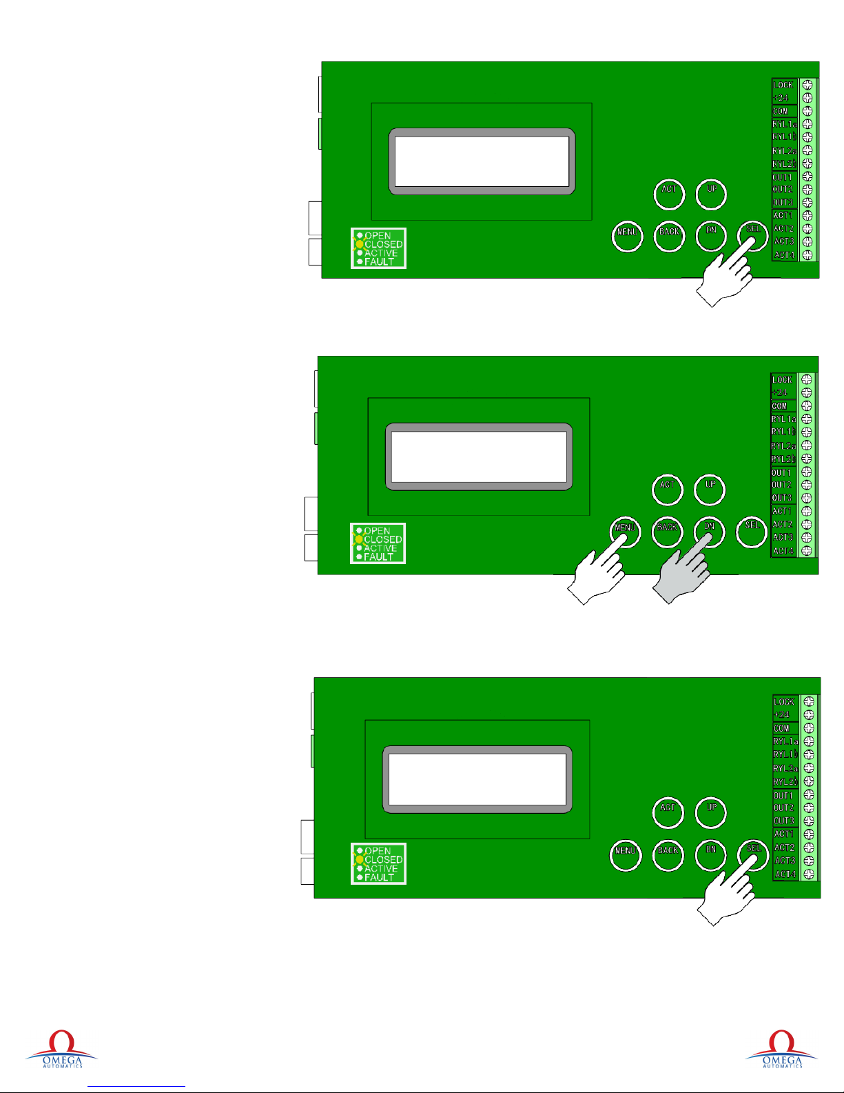
Programming:
Step 5:
- Press SEL to exit parameter
Forced Relearn
Step 1:
- From "DOOR CLOSED" screen
- Press MENU
- Press DN twice
SETTINGS (01)
Overload 50
DOOR CLOSED
Step 1b:
- Screen reads "MAIN MENU"
(Calibrate)
- Press SEL twice for next screen
X-2
MAIN MENU
(Calibrate)
X-2
O M E G A A U T O M A T I C S 2 0 1 8
V 2 . 0
Page 11

Programming:
Step 3:
- Press MENU then ACT
- Screen reads "CALIBRATE"
Step 3b:
- Screen reads "RELEASE STRIKE"
(Learning)
- Once one cycle is complete board
has relearned itself
CALIBRATE
Relearn Next ACT
RELEASE STRIKE
(Learning)
O M E G A A U T O M A T I C S 2 0 1 8
V 2 . 0
Page 12

Cover:
- Snap cover onto backer plate
- Attach cover fasteners
Stickers:
- Apply warning stickers to door
- Refer to local codes for proper heights
Cover
Cover Fastener
AAADM
Sticker
O M E G A A U T O M A T I C S 2 0 1 8
58" ±5
42"
V 2 . 0
 Loading...