

Page 1
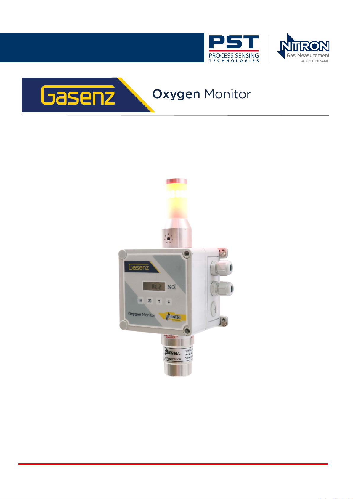
User Manual NT-UM-2107-EN-01
NT-UM-2107-EN-01 | P/N: 08-424
Page 2

Gasenz Oxygen Monitor User Manual
Issue No. Description Date
Rev 0 Original document issued for the models with serial
05/2024
number format 2xxxxx.
Rev 1 Updated wiring and compliance information 07/2025
Author
Initials
CK
CK, IM
Gasenz Oxygen Analyzer
For contact information, visit
Ntron.com
This document is the property of Ntron Gas Measurement Ltd. and may not be copied or otherwise reproduced,
communicated to third parties, nor stored in any Data Processing System without the express
written authorization of Ntron Gas Measurement.
© 2025 Ntron Gas Measurement
ii ProcessSensing.com
Page 3

Gasenz Oxygen Monitor User Manual
Before using your Gasenz
Safety information
Please read this manual, ensuring that you fully understand the content before attempting to
install, maintain or use the Gasenz. Important safety information is highlighted throughout this
document as follows:
The warning symbol indicates instructions that must be followed to avoid minor, serious or
even fatal injury to personnel.
The caution symbol indicates instructions that must be followed to avoid damage to equip-
ment (hardware and/or software) or the occurrence of a system failure.
NOTE highlights an essential operating procedure, condition, or statement.
Zirconia sensors operate at moderately elevated temperatures. Handling them without the
correct personal protective equipment (PPE) can cause minor discomfort.
Abbreviations
AC Alternating current
DC Direct current
o
C Degrees celcius
o
F Degrees fahrenheit
EC Electrochemical
ELV Extra Low Voltage
FSD Full-scale deflection
g Grams
GND Ground
kg Kilogram
LED Light emitting diode
LPM Liters per minute
mA Milliampere
O
2
OEM Original equipment manufacturer
oz Ounces
PC Personal computer
PCB Printed circuit board
PLC Programmable logic controller
PPM Parts per million
SCFH Standard cubic feet per hour
Oxygen
ProcessSensing.com iii
Page 4

S-S Solid-state
SS Stainless steel
Gasenz Oxygen Monitor User Manual
iv ProcessSensing.com
Page 5

Gasenz Oxygen Monitor User Manual
Contents
Before using your Gasenz ................................................................................................iii
Safety information ....................................................................................................................................iii
Abbreviations ..............................................................................................................................................iii
1 Introduction to Gasenz ....................................................................................................1
1.1 Overview .................................................................................................................................................1
1.2 Sensor ......................................................................................................................................................2
1.2.1 Zirconia technology .................................................................................................................................. 2
1.2.2 Electrochemical technology .................................................................................................................. 2
1.3 Status Indicator ....................................................................................................................................2
1.4 Applications ..........................................................................................................................................2
1.5 Considerations .....................................................................................................................................3
1.6 Safety approvals ..................................................................................................................................3
2 Installation .........................................................................................................................4
2.1 Unpack the Gasenz ............................................................................................................................5
2.2 Locate your Gasenz ............................................................................................................................5
2.3 Mount your Gasenz ............................................................................................................................6
3 Connection ........................................................................................................................8
3.1 Wiring Your Gasenz ...........................................................................................................................9
3.1.1 Connect your sensor ................................................................................................................................ 9
3.2 RS232 .................................................................................................................................................... 10
3.3 Analog output ................................................................................................................................... 10
4 Operation .........................................................................................................................11
4.1 User interface .................................................................................................................................... 11
4.2 Setup ..................................................................................................................................................... 12
4.2.1 Passkeys ......................................................................................................................................................12
4.2.2 Calibrate your Gasenz to your sensor .............................................................................................12
4.2.3 New sensor data ......................................................................................................................................13
4.3 Menus and tasks .............................................................................................................................. 14
4.3.1 Adjust analog output FSD ....................................................................................................................14
4.3.2 Set 4 mA / 20 mA output .....................................................................................................................14
4.3.3 Simulate analog output ........................................................................................................................15
4.3.4 Restore factory settings ........................................................................................................................15
4.3.5 View diagnostics ......................................................................................................................................15
4.3.6 Set relays .....................................................................................................................................................16
4.3.7 Alarm levels ................................................................................................................................................17
4.3.8 Alarm hysteresis .......................................................................................................................................17
5 Maintenance ................................................................................................................... 19
5.1 General ................................................................................................................................................. 19
5.2 Replace the sensor .......................................................................................................................... 19
5.2.1 Electrochemical ........................................................................................................................................20
5.2.2 Zirconia ........................................................................................................................................................21
5.2.3 Re-configure ..............................................................................................................................................23
ProcessSensing.com v
Page 6

Gasenz Oxygen Monitor User Manual
5.3 Considerations and troubleshooting ........................................................................................23
6 Appendices ..................................................................................................................... 24
Appendix A - Technical Specifications ............................................................................................24
Appendix B - Menu list ..........................................................................................................................25
Appendix C - Marking drawings ........................................................................................................26
Appendix D - Quality, Recycling, and Warranty Information .................................................27
vi ProcessSensing.com
Page 7
Gasenz Oxygen Monitor User Manual
1 Introduction to Gasenz
This manual is applicable to the Gasenz oxygen monitor with a serial number in this format: 2xxxxx. If
you require user documentation for Gasenz models with a different serial number format, please
contact us at: [email protected].
Gasenz is mountable on a wall or vertical surface, for monitoring % oxygen volume levels in an
ambient environment.
This product is for indoor use only. If this equipment is used in a manner not specified by the
manufacturer, the protection provided by this equipment may be impaired.
1.1 Overview
The Gasenz is designed for personnel protection in applications where there is a risk of oxygendeficiency or enrichment, and in laboratory applications.
Gasenz is complete with integrated audible-visual alarms, and a long-life zirconia (ZR) or cost-effective
electrochemical sensor options. Both have a measurement range up to 0...25 % O
.
2
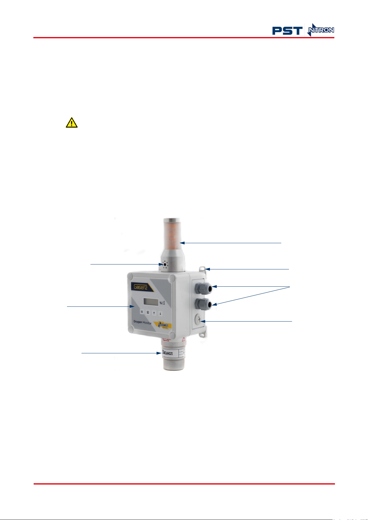
Light tower
Audible output
User interface
Wall mount fitting
Cable glands
Trunking hole cover
Sensor
Figure 1. Gasenz (pictured with zirconia sensor)
The Gasenz module contains measurement electronics. The sensor is connected to the electronics via
PCB-mounted screw terminals. The sensor operates from the exterior of the monitor and is
replaceable. For further information refer to "5.2 Replace the sensor" on page 19.
Gasenz is suitable for mounting in an operational location without further mechanical protection,
following a suitable risk assessment carried out by an appropriately experienced or qualified person.
Risk assessment should include:
• Potential hazards to personnel or plant from the intended use of the equipment
ProcessSensing.com 1
Page 8

• Hazards when maintaining the equipment
• Further safety or environmental parameters to be considered.
1.2 Sensor
The Gasenz is designed to interface with either of the following two principal types of sensor
technology:
• Electrochemical (EC)
• Zirconium dioxide (ZR)
Please refer to "Appendix A - Technical Specifications" on page 24 for full specifications.
1.2.1 Zirconia technology
These sensors are very stable over their lifespan and don’t usually require calibration as frequently as
some other sensor technologies.
A calibration check can be made at intervals suited to your application.
Gasenz Oxygen Monitor User Manual
Avoid exposing the sensor to moisture or wetting, particularly if the gas for measurement contains
condensible vapors or entrained liquids.
Halogens, organic vapors, H
lead to inaccurate measurements.
2
1.2.2 Electrochemical technology
Ntron electrochemical sensors are galvanic cells capable of superior performance, accuracy, and
stability. The operational life is typically up to 18 months and the sensor is designed to be unaffected
by the presence of other background gases.
1.3 Status Indicator
A two-lamp high intensity LED light tower provides indication of Normal/Ready operational status or
condition (green) and Alarm condition (red).
The Alarm condition is triggered when a gas measurement level (which can be preset) is reached.
When the red alarm light is illuminated, a sounder will also be activated, providing personnel with both
audible and visual indications of an Alarm condition. Refer to "4.3.7 Alarm levels" on page 17 for more
information.
S and SO4 should also be avoided as they may reduce sensor life and
The light tower can be wired for either high and low O
indication, or low O2 indication only.
2
1.4 Applications
Typically, our Gasenz oxygen monitors can be used in the following applications:
• Personnel protection
• Medical
2 ProcessSensing.com
Page 9

Gasenz Oxygen Monitor User Manual
• Laboratories
• Gas generation
• Hypoxic air fire prevention systems.
1.5 Considerations
The efficacy of the installed monitor is your responsibility.
When Gasenz is used with other equipment please consider the following:
• Temperature testing should be carried out.
• The products covered should be evaluated to the environmental conditions as defined by the
standard up to 2000 m altitude and within the temperature range applicable to your sensor, refer
to "Appendix A - Technical Specifications" on page 24 for more detail.
• Grounding application requires assessment.
• The current rating and size of the power supply cable should be appropriate to your equipment.
• The products covered by this manual are to be installed as per the manufacturer’s instructions.
• Only the sensor provided by the manufacturer is to be used with the module.
1.6 Safety approvals
The CE marking indicates Gasenz
conformity to European health,
safety, safety and environmental
protection directives.
This ETL marking proves
Gasenz is compliant to North America
safety and industry standards.
ProcessSensing.com 3
Page 10

2 Installation
NOTE: Installation, operation and maintenance of this equipment should be carried out only by
appropriately trained and suitably qualified technicians in accordance with the instructions in this
user manual, and any applicable standards/certificates associated with the country, industry and
application.
ous or even fatal injury. In this regard, the manufacturer will not be held
liable.
NOTE: The operator may only perform modifications and repairs to the equipment or system with
written approval from the manufacturer.
Do not operate damaged equipment. If faults cannot be rectified, the equipment must be
taken out of service and secured against unintentional commissioning.
Gasenz Oxygen Monitor User Manual
Failure to correctly adhere to these instructions may result in seri-
Before installing your Gasenz, ensure that its specifications are suitable for the installation location.
4 ProcessSensing.com
Page 11
Gasenz Oxygen Monitor User Manual
2.1 Unpack the Gasenz
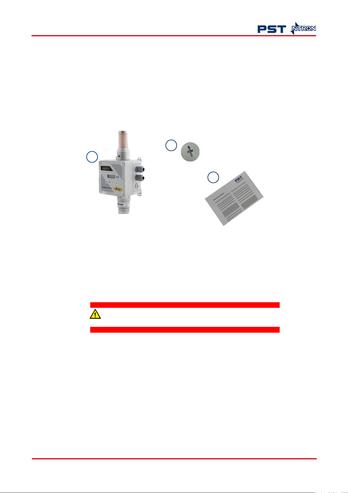
Your Gase nz monitor pack is comprised of the following equipment (pack contents may vary
depending on your specification):
1. Gasenz module including sensor in sensor housing (ZR sensor pictured)
2. Spare trunking hole cover
3. Factory calibration certificate.
1
2
3
2.2 Locate your Gasenz
The Gasenz is an oxygen detector system and should be installed so that it can effectively monitor a
plant area where low oxygen levels could occur.
Gasenz is a ‘Safe Area’ device and is not suited to Hazardous Areas.
NOTE: Please ensure the module is located so that an early warning can be given if the atmosphere
becomes oxygen deficient.
The following background gases should be avoided to preserve sensor life:
• Halogens
• F
• CI
• Br
• SOx
S
• H
2
• Vapors of silicon-sealing compounds
Figure 2. Contents of pack
ProcessSensing.com 5
Page 12

Gasenz Oxygen Monitor User Manual
• Adhesives.
The densities of gases in air is identified in European standard EN 617791:2000.
NOTE: High pressure gas leaks can result in a drop in gas temperature, which could temporarily
increase gas density.
When choosing a suitable location consider evaluating the following:
• Gasenz dimensions (refer to Figure 4 on page 7)
• Proximity to potential leak source: the monitor should be installed close to potential leak sources
but not so close that they respond to inconsequential leakage
• Constituent gas to be detected
• Possibility of pressurized gas release, evaporation or liquid leaks
• Air movements, ventilation, topography, temperature - a well-designed ventilation system will
incorporate a number of air changes per hour, limiting potential gas build-up or depletion of
oxygen
• Number of personnel at location.
2
Gasenz can cover an area of around 50 m
, this equates to an approximate radius of 5 meters from
the monitor. If the monitor is mounted on a wall as shown in Figure 3, the area covered is halved.
However, applications may vary, and careful consideration is required to determine the number of
monitors required.
Front Side
2.3 Mount your Gasenz
Gasenz is suitable for mounting in an operational location without further mechanical protection,
following a suitable risk assessment carried out by an appropriately experienced or qualified person.
Risk assessment should include:
• Potential hazards to personnel or plant from the intended use of the equipment
• Hazards when maintaining the equipment
5m
5m
Figure 3. Monitoring coverage
6 ProcessSensing.com
Page 13
Gasenz Oxygen Monitor User Manual
• Further safety or environmental parameters to be considered.
Before mounting your Gasenz monitor, ensure that its specifications are suitable for the process,
where it will be installed. See "Appendix A - Technical Specifications" on page 24.
In general, fixed systems should be installed so that maintenance of other units does not compromise
the safety of the premises being monitored. Fall-back Gasenz units may therefore be required to
maintain an adequate safety level.
The module can be mains powered (85...230 V AC or 24 V DC) depending on your specification.
Please ensure:
• Installation, wiring, and any upstream protective devices are provided and installed in line with the
appropriate regulatory requirements for your country and industry
• A suitable cable is used, appropriate to the protective equipment installed and the connection
terminal sizes on your Gasenz.
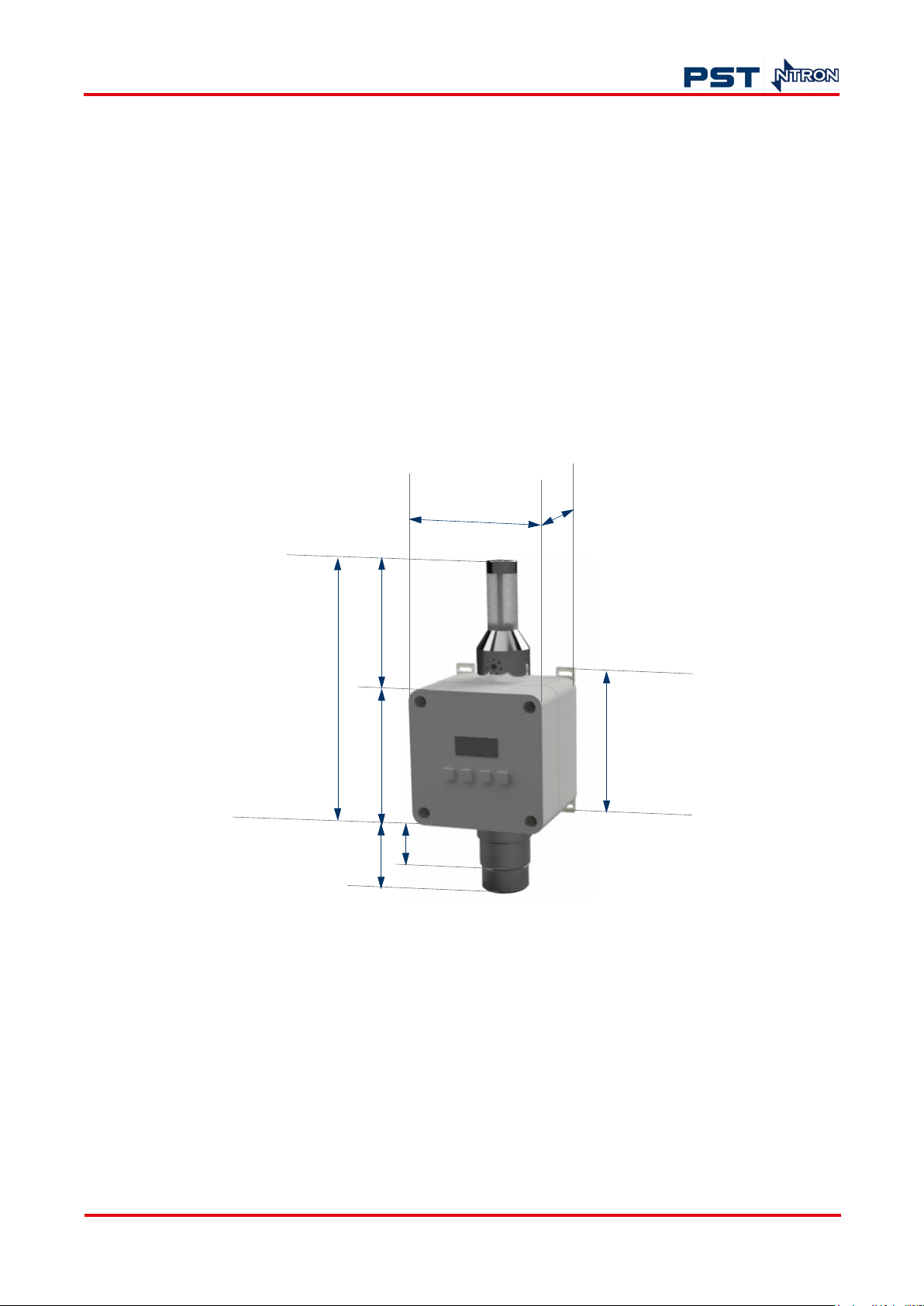
110
109
219
110
40 (EC)
60 (ZR)
Figure 4. Gasenz dimensions (in mm)
90
130
To mount your Gasenz to a wall or vertical surface, secure the module with suitable fixings for the
surface where it will be mounted.
The mounting surface should provide secure and vibration-free support, away from heat sources or
sites where excessive moisture is present.
NOTE: Gasenz should be mounted upright with the light tower at the top of the module and the
sensor at the bottom as shown in Figure 4.
ProcessSensing.com 7
Page 14

3 Connection
Your Gasenz will arrive fully wired, with your chosen sensor also wired, calibrated, and installed.
All connections to the module are provided in the form of screw terminals. The pin-outs for the
module are shown below.
You are responsible for making field connections using suitable cabling in line with local regulation
codes, and accounting for the power requirements for Gasenz, which are detailed in "Appendix A Technical Specifications" on page 24.
A 500 mA anti-surge fuse is fitted to the Gasenz module and is not user replaceable. It is located next
to the power input terminals.
correct. See "Appendix A - Technical Specifications" on page 24 for
guidance.
Gasenz Oxygen Monitor User Manual
Before switching on your monitor and sensor, ensure the voltage is
8 ProcessSensing.com
Page 15
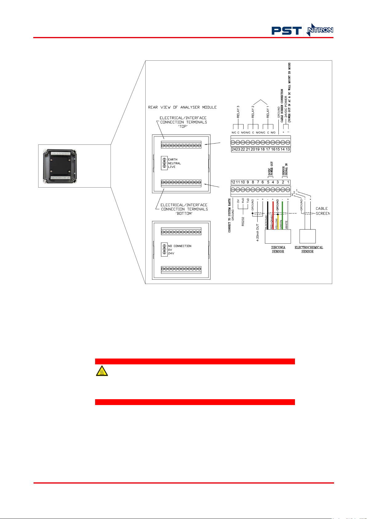
Gasenz Oxygen Monitor User Manual
3.1 Wiring Your Gasenz
(Cover off)
For audiblevisual alarms
3.1.1 Connect your sensor
NOTE: EC and ZR sensors should be connected at terminals 1...3 (inclusive). Terminals 4 and 5
should be used only to connect ZR sensors, as shown in Figure 5.
ZR sensors operate at moderately elevated temperatures, which
can cause minor discomfort if in contact with unprotected hands and
fingers for a prolonged period.
Figure 5. Terminal wiring
ProcessSensing.com 9
Page 16

3.2 RS232
If you require RS232 connection, please contact us:
Em a i l : ie . n t r on . s a l e s @ p ro ce s s s e n s i n g .c o m
Phone:+353 46 907 1333.
3.3 Analog output
Analog output enables communication of detected gas levels with external equipment (such as data
logge rs, remote displays). The output is equal to the current source (4...20 mA), where 4 mA
represents zero gas and 20 mA represents gas at the sensor FSD.
Gasenz Oxygen Monitor User Manual
10 ProcessSensing.com
Page 17
Gasenz Oxygen Monitor User Manual
4 Operation
When Gasenz is first powered up, all the display segments are displayed followed by the start-up
display sequence below:
• Software version number
• The company name
• The sensor type
• The gas level.
On completion of the display sequence, the module is operational.
4.1 User interface
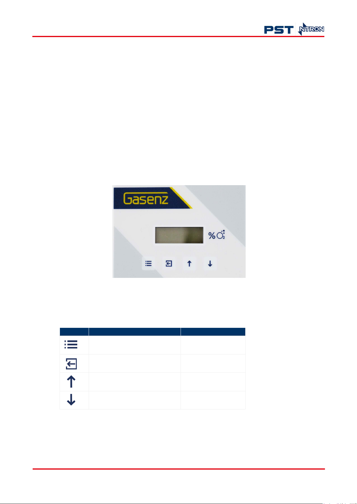
The Gasenz has a 1-inch LCD display and a four-key keypad interface.
Figure 6. Gasenz user interface
The keypad buttons can be used as identified in the table below:
Table 1: Interface key functions
Key Function Additional function
Menu open/close
Enter Number 1
Next (increment) Number 2
Previous (decrement) Number 3
ProcessSensing.com 11
Page 18

4.2 Setup
The menu system enables calibration and configuration of your module to your equipment. Refer to
"Appendix B - Menu list" on page 25 for guidance.
4.2.1 Passkeys
Gasenz uses a passkey system to restrict changes that could compromise use of the equipment. The
factory set passkey for level 2 access is 1331. For level 3 access, the passkey in 12231.
The passkey feature can be enabled or disabled. There are three menu access levels (1, 2, and 3) and
each level allows access to specific menu options. See "Appendix B - Menu list" on page 25 for details.
When a particular menu level is accessed, the user has 10 seconds to enter a specific menu on the
chosen level before automatic exit is carried out. On accessing a menu, the user then has 10 minutes
to make adjustments and save changes.
To enable the passkey function:
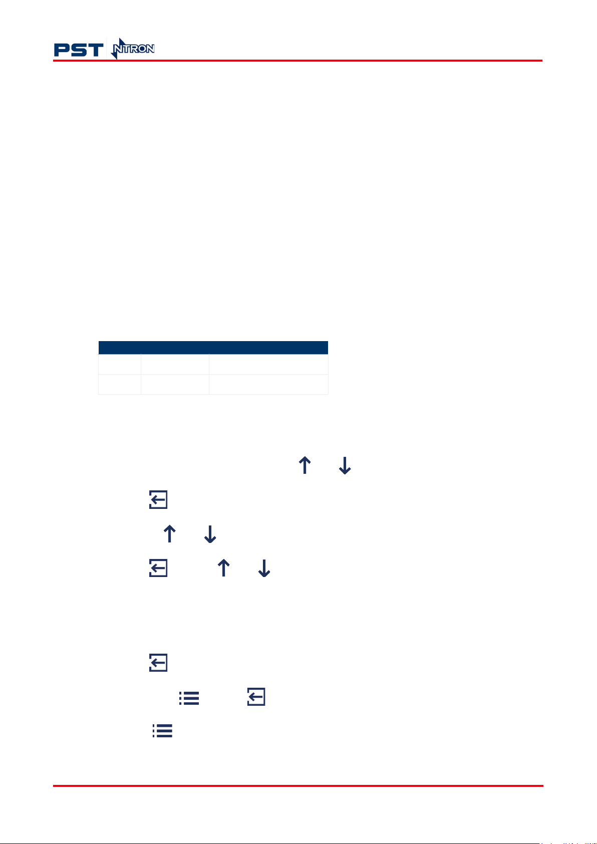
1. Press .
Gasenz Oxygen Monitor User Manual
2. Using the and buttons, select menu option E:20.
3. Press . The display will show the current status as On or Off.
4. Use the and keys to select your desired status.
5. Press to save your changes.
6. Press to exit.
4.2.2 Calibrate your Gasenz to your sensor
Your calibration requirements and frequency will vary depending on your sensor technology and
application. You should determine a reasonable schedule according to these factors and your own
requirements.
To calibrate Gasenz to your sensor:
1. Press on the keypad.
The word “PASS” will appear on the display. You will require level 3 access to change this setting.
2. Enter the passkey for level 3 access.
The numerical combination can be entered using the keypad. Please refer to "Table 1: Interface
key functions" on page 11. As each key is pressed the letters “Po” will be displayed on the screen.
3. Once the passkey is entered, press .
4. Use the and keys to select E:1.
12 ProcessSensing.com
Page 19

Gasenz Oxygen Monitor User Manual
5. Press . Allow time for the sensor to respond (approximately 2 minutes in ambient air, a lower
Oxygen concentration may require more time for the reading to stabilize).
6. Use the and keys to set the reading to that of the calibration gas level.
7. Press to span the sensor, “_ _ _ _” will appear on the display to confirm calibration.
NOTE: Pressing instead of will exit without saving.
8. Wait until the reading is stable before pressing . If it is unstable press to span the
sensor.
9. Press to exit.
NOTE: The sensor reading will be displayed as a % value on exit when the button is pressed.
This value is a percentage of the initial calibration value set via New Sensor Data in menu E:14. Each
time a new sensor is connected and calibrated, the New Sensor Data should be set.
4.2.3 New sensor data
You can use this function to set the initial sensor calibration data. It enables you to periodically check
the percentage of your sensor’s capacity.
1. After entering your menu level, use the and keys to select E:14.
2. Press . The display shows 100. This indicates that your sensor is at 100 % functionality.
3. Press again to store the new sensor data to the module’s memory.
NOTE: Pressing instead of will exit without saving.
Press to exit.
ProcessSensing.com 13
Page 20

4.3 Menus and tasks
NOTE: The menus and functions available will vary according to your sensor and Gasenz firmware.
To access the menus:
1. Press on the keypad.
The word “PASS” will appear on the display. For access to level 1 options, press again,
otherwise proceed to step 2.
2. Enter the passkey for your menu level access.
The numerical combination can be entered using the keypad. Please refer to "Table 1: Interface
key functions" on page 11. As each key is pressed the letters “Po” will be displayed on the screen.
3. Once the passkey is entered, press .
4. Use the and keys to select the required menu.
Gasenz Oxygen Monitor User Manual
4.3.1 Adjust analog output FSD
1. After entering your menu level, use the and keys to select E:2.
2. Press .
3. Use the and keys to adjust the FSD to the required level.
4. Press to save your changes.
NOTE: Pressing instead of will exit without saving.
5. Press to exit. The sensor FSD will be displayed when you press the key to exit.
4.3.2 Set 4 mA / 20 mA output
Monitor the current sourced from the analog output of the OEM module using a multimeter set to
read milliamps.
1. After entering your menu level, use the and keys to select E:3 (select E:4 for 20 mA
output).
2. Press .
3. Use the and keys to adjust the output to 4 mA (or 20 mA).
4. Press to save your changes.
14 ProcessSensing.com
Page 21

Gasenz Oxygen Monitor User Manual
NOTE: Pressing instead of will exit without saving.
5. Press to exit.
The 4 mA or 20 mA factor will be displayed when you press the key to exit.
4.3.3 Simulate analog output
The analog output can be tested for functionality, allowing you to simulate analog output.
1. After entering your menu level, use the and keys to select E:5.
2. Press .
3. Use the and keys to adjust the analog output. The value displayed will be equivalent to
the analog output.
4. Press to exit.
The module will return to its current analog output settings.
4.3.4 Restore factory settings
You can restore configuration to the default values using this function.
NOTE: Factory restore will overwrite all previous calibration data for the selected sensor excluding
those set at the factory.
1. After entering your menu level, use the and keys to select E:6.
2. Press and hold until “____” is displayed. Your module is now restored to its factory settings.
3. Press to exit.
4.3.5 View diagnostics
This is a view-only feature. Configuration changes cannot be made.
1. After entering your menu level, use the and keys to select E:8.
2. Press . The display will alternate between the current value and diagnostic code.
3. Use the key to select the diagnostic code.
4. Press to exit the menu.
ProcessSensing.com 15
Page 22
4.3.6 Set relays
NOTE: Changing this setting will alter the operating point of the indicator unit and relays which will
affect the monitor’s capability to announce dangerous Oxygen levels.
Gasenz is fitted with three relays that operate in conjunction with one of three alarm levels. You can
configure them using this function.
Relay 1, or relays 1 and 2 are configured and wired to operate the light tower indication unit, making
them unavailable for other assignment. The relays that are not used for the light tower are available
for you to connect.
Relay 3, and relay 2 (if available) are volt-free contacts, 6A @ 250 V AC rated.
• Relay 1 is associated with alarm level 1
• Relay 2 is associated with alarm level 2
• Relay 3 is associated with alarm level 3.
You can choose energize “E” or de-energize “D” each relay when the module alarms are inactive.
Relays can also be set to act on rising “R” or falling “F” gas levels.
Gasenz Oxygen Monitor User Manual
Typical operational settings
High O2 = 23% Rising alarm
Low O2 = 19% Falling alarm
If High and Low level alarm functionality is required, then only one interface relay will be available to
you for external connection. If only Low level alarm functionality is required, you will have two
interface relays to connect to.
1. After entering your menu level, use the and keys to select E:17.
2. Press . The display shows r:1.
3. Use the and keys to select a relay.
4. Press , then use and keys to choose from the following options:
E:r Normally energized, rising alarm
d:r Normally de-energized, rising alarm
E: F Normally energized, falling alarm
d:F Normally de-energized, falling alarm.
5. Press to store the new data.
NOTE: Pressing instead of will exit without saving.
6. Press to exit.
16 ProcessSensing.com
Page 23

Gasenz Oxygen Monitor User Manual
4.3.7 Alarm levels
NOTE: Gasenz is factory configured with standard alarm level settings unless you have specified
your requirements. Changing this setting will alter the operating point of the indicator unit and
relays which will affect the monitor’s capability to announce dangerous Oxygen levels.
Relays 1 and 2 are factory configured for 19% volume O
falling (Relay 1) and 23% volume O2 rising
2
(Relay 2). Relay 3 is set at 25% rising by default.
NOTE: For guidance, 19.5% is the OHSHA-recognized US lower alarm level for O
Set the alarm level operation using this function.
• Alarm level 1 is associated with relay 1
• Alarm level 2 is associated with relay 2
• Alarm level 3 is associated with relay 3.
1. After entering your menu level, use the and keys to select E:18.
2. Press . The display shows A:1.
3. Use the and keys to select an alarm level.
4. Press , then use and to set the alarm level value.
5. Press to save your changes.
depletion.
2
NOTE: Pressing instead of will exit without saving.
6. Press to exit.
4.3.8 Alarm hysteresis
A hysteresis value is associated with the alarm levels to avoid relay chattering as the unit enters and
exits alarm conditions. It is displayed as a percentage point, between 1 and 10, of the alarm set.
Setting a value of 1 disables the relays.
ProcessSensing.com 17
Page 24

Gasenz Oxygen Monitor User Manual
1. After entering your menu level, use the and keys to select E:19.
2. Press . The display shows the alarm hysteresis level.
3. Use the and keys to set the level.
4. Press to save your changes.
NOTE: Pressing instead of will exit without saving.
5. Press to exit.
18 ProcessSensing.com
Page 25

Gasenz Oxygen Monitor User Manual
5 Maintenance
The Gasenz will provide reliable and fault-free service for many years if cared for correctly.
5.1 General
To maintain performance, the sensor in your Gasenz module will require replacement. Please check
"Appendix A - Technical Specifications" on page 24 for frequency. During sensor replacement, it is
recommended that light cleaning and a routine inspection is carried out.
Never use chemical cleaning agents or high pressure water or steam to clean the equipment.
Do not submerge in water.
To carry out routine maintenance and inspection:
1. Use a clean, damp cloth to clean the gas detector head.
2. Ensure the sensor housing aperture is not obstructed (where applicable).
The maximum interval between routine inspections should be assessed by the person carrying out
calibrations. It will depend on your application and the environment in which the module is installed.
5.2 Replace the sensor
When your sensor reaches the end of its serviceable life, calibration can no longer be performed and
the sensor must be replaced.
A regular program of calibration will mitigate against sudden sensor failure. It is advisable to establish
a program of preventative maintenance to ensure process downtime is kept to a minimum or avoided.
Your new sensor should only be removed from its packaging when your Gasenz is installed and ready
to begin gas measurement.
The Gasenz module and sensors can be mains powered (110...240
V AC).
Ensure that any installation wiring and upstream protective devices are
provided in line with the regulatory requirements for your country and
industry. See "Appendix A - Technical Specifications" on page 24 for
guidance.
ProcessSensing.com 19
Page 26
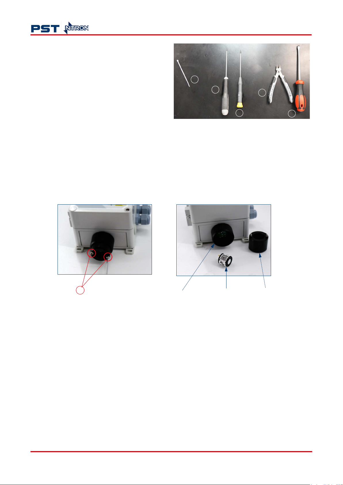
To replace your sensor, you will need:
1. Cable tie (ZR only)
2. 2.5 mm hex-driver
3. 3 mm flat-head screwdriver (ZR only)
4. Snips (ZR only)
Gasenz Oxygen Monitor User Manual
1
2
4
5. Large flat-head screwdriver (ZR only).
5.2.1 Electrochemical
1. Disconnect the power to your Gasenz.
2. Remove the screws from the bottom of the sensor housing using a 2.5 mm hex-driver, as shown
in Figure 7.
3. Remove the cover to reveal the electrochemical sensor.
4. Gently unplug the old sensor.
3
5
2
Sensor housing
EC sensor
Sensor cover
Figure 7. Replacing the EC sensor
5. Remove the new sensor from its packaging and plug it into the PCB inside the sensor housing,
ensuring it is correctly aligned.
6. Close and secure the sensor cover using the 2.5 mm hex-driver. Now restore power.
7. Follow instructions for calibration in "4.2.2 Calibrate your Gasenz to your sensor" on page 12
and/or "4.2.3 New sensor data" on page 13.
20 ProcessSensing.com
Page 27

Gasenz Oxygen Monitor User Manual
8. Dispose of the old sensor appropriately, adhering to local codes.
Electrochemical sensors contain a corrosive electrolyte and must
not be opened, neither should sealed membranes be removed. Eye and
hand protection must be worn if the sensor is leaking. Wipe and flush
any electrolyte spillage.
Electrolyte can be fatal if swallowed.
5.2.2 Zirconia
NOTE: ZR sensors should be connected at terminals 1...3 (inclusive) as shown in Figure 5.
ZR sensors operate at moderately elevated temperatures which
can cause minor discomfort if in contact with unprotected hands and
fingers for a prolonged period.
1. Disconnect the power to your Gasenz. Ensure the sensor has cooled down before continuing.
2. Using a large flat-head screwdriver, open the main Gasenz casing.
3. Remove the hex screws located on the inside of the Gasenz using a 2.5 mm hex-driver, as shown
in Figure 8 (highlighted in red).
4. With a 3 mm screwdriver, loosen the sensor terminal screws (as highlighted in blue in Figure 8) to
disconnect the sensor from the module.
5. Use snips to remove the cable tie holding the wires together.
ProcessSensing.com 21
Page 28
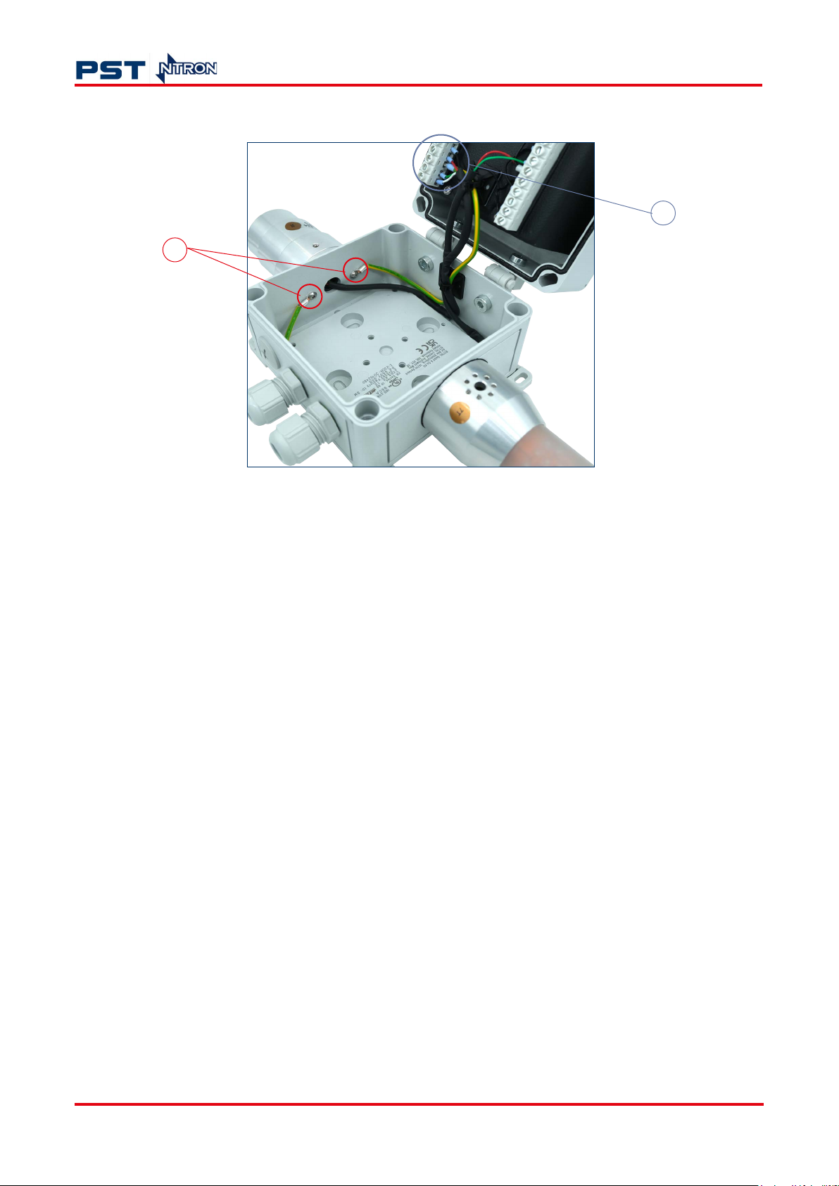
6. Gently remove the old sensor in its housing from Gasenz.
3
Gasenz Oxygen Monitor User Manual
4
Figure 8. Replacing the ZR sensor
7. Remove the new sensor (in its housing) from its packaging.
8. Thread the wires through the hole at the base of Gasenz to bring them inside the main housing.
9. Align the screw holes with those on the Gasenz (highlighted in red in Figure 8).
10. Connect the new sensor using the 3 mm screwdriver to tighten the appropriate terminal screws.
Refer to Figure 5 on page 9 for guidance.
11. Secure the cables inside the Gasenz housing using a cable tie. Use snips to remove any excess.
12. Take the 2.5 mm hex-driver to tighten the hex screws that attach the sensor housing to the base
of your Gasenz.
13. Close the Gasenz cover and secure it using the large flat-head screwdriver. Now restore power.
14. Follow instructions for calibration in "4.2.2 Calibrate your Gasenz to your sensor" on page 12
and/or "4.2.3 New sensor data" on page 13.
15. Dispose of the old sensor and sensor housing appropriately, adhering to local codes.
22 ProcessSensing.com
Page 29

Gasenz Oxygen Monitor User Manual
5.2.3 Re-configure
The diagram below shows the sequence for sett ing up Gasenz a fter replacing t he sensor.
Sensor
Calibration
New sensor
data
Figure 9. Gasenz setup sequence
NOTE: Gasenz must be correctly configured for the sensor being used before carrying out any other
tasks.
5.3 Considerations and troubleshooting
• A faulty sensor or one that is incorrectly installed will display ‘FLT’ on your Gasenz display.
• Do not expose the sensor to moisture in an un-powered state. If this happens, allow the sensor to
dry out.
Configuration
Begin gas
measurement
ProcessSensing.com 23
Page 30

Gasenz Oxygen Monitor User Manual
6 Appendices
Appendix A - Technical Specifications
Sensor
Zirconia (ZR) Electrochemical (EC)
Measurement Range 0…25 %
Output Resolution 0.01 %
Pressure Range 900…1100 mBar
Response time (T90) < 15 seconds within selected range @ 25 °C (77 °F) within selected range
Operating Temperature Range -25 °C…+60 °C (-13 °F…+140 °F) 0 °C…+45 °C (+32 °F…+113 °F)
Life Expectancy Up to 5 years Up to 18 months
Humidity 0…95 %rh non-condensing (with normal use)
Shelf Life Unlimited Up to 3 months
Calibration Interval (application
dependent)
12 months 3...6 months
Monitor
Electrical
Display LCD, %O
Output Signal 4...20 mA
Digital Communications RS232
Relay Output Options 1 off relay, dry contact 5 Amp-rated
Power Supply 85...230 V AC (50...60 Hz) or 24 V DC
Maximum Power Consumption 7.2 W 3.6 W
Indicators LCD, audible and visual alarms
(2 relay outputs assigned to control light tower indicator)
Mechanical
Housing Material ABS
Mounting Wall / vertical surface
Standards and Certification
ETL: UL-61010-1, EMC: EN 50270
abs
2
24 ProcessSensing.com
Page 31

Gasenz Oxygen Monitor User Manual
Appendix B - Menu list
Menu option Task
= Accessible by all users
E:1 Calibrate sensor
= Accessible with password levels 2 & 3
E:2 Analog output FSD
= Access with password level 3 only
E:3 Set 4 mA
E:4 Set 20 mA
E:5 Analog output simulation
E:6 Factory restore
E:8 Diagnostics
E:14 New sensor data
= No password
= 1331
= 12231
E:17 Relay
E:18 Alarm levels
E:19 Alarm hysteresis
E:20 Password enable/disable
NOTE: Available menu options may vary according to firmware version and sensor type.
ProcessSensing.com 25
Page 32
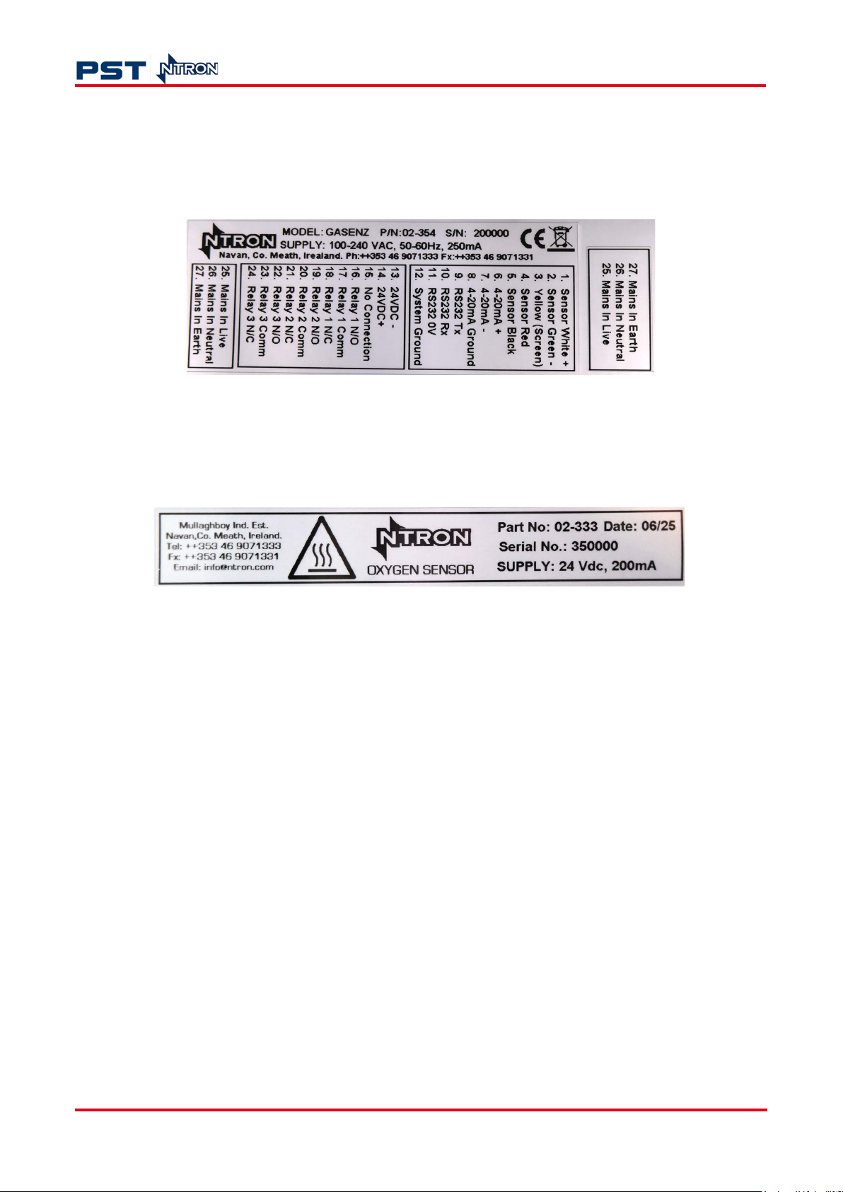
Appendix C - Labels
Gasenz Oxygen Monitor User Manual
Gasenz monitor label
Gasenz zirconia sensor label
26 ProcessSensing.com
Page 33

Gasenz Oxygen Monitor User Manual
Appendix D - Quality, Recycling, and Warranty Information
Ntron is part of the Process Sensing Technologies (PST) group and complies with
applicable national and international standards and directives.
Full information can be found on our website at https://www.processsensing.com/enus/compliance.
The compliance site contains information on the following directives:
• ATEX (equipment for explosive atmosphere)
• REACH (Registration, Evaluation, Authorization, and Restriction of Chemicals)
• RoHS (Restriction of Hazardous Substances in electrical and electronic equipment
• ETL (The ETL mark is proof of product compliance to North American safety
standards.
• WEEE (Waste Electrical and Electronic Equipment recycling
• Recycling policy
• Warranty and returns.
ProcessSensing.com 27
Page 34

ProcessSensing.com
© 2025 Ntron Gas Measurement
 Loading...