

Page 1
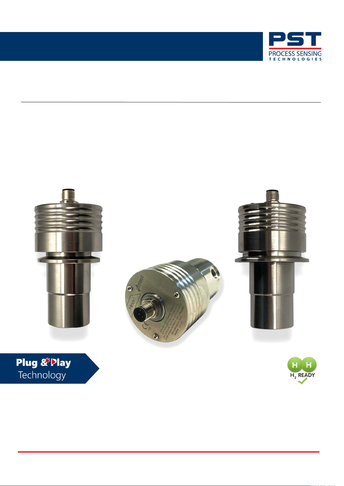
Minox i Oxygen Transmitter
User Manual
PST-UM-2010-EN-2.2
PST-UM-2010-EN-2.2 06/2024
Page 2

Minox i Oxygen Transmitter User Manual
Revision No. Description Date Author
1 Original document issued 03/2022 CdF
2 Re-brand template applied 08/2022 IMC
2.1 Updated calibration information and technical specifications 08/2023 IMC
2.2 Updated certification information 06/2024 IM
Minox i Oxygen Transmitter
For PST contact information, visit
ProcessSensing.com
This document is the property of Process Sensing Technologies and may not be copied or otherwise reproduced, communi-
cated to third parties, nor stored in any Data Processing System without the express written authorization of Process Sensing
Technologies.
©2024 Process Sensing Technologies
ii ProcessSensing.com
Page 3

Minox i Oxygen Transmitter User Manual
Before using your Minox i
Safety information
Please read this manual, ensuring that you fully understand the content before attempting to install,
maintain or use the Minox i. Important safety information is highlighted throughout this document as
follows:
The warning symbol indicates instructions that must be followed to
avoid minor, serious or even fatal injury to personnel.
The caution symbol indicates instructions that must be followed to avoid damage to equip-
ment (hardware and/or software) or the occurrence of a system failure.
NOTE: Highlights an essential operating procedure, condition, or statement.
ProcessSensing.com iii
Page 4

Abbreviations
AC Alternating current
DC Direct current
o
C Degrees celcius
o
F Degrees fahrenheit
EC Electrochemical
g Grams
GND Ground
kg Kilogram
LED Light emitting diode
LPM Liters per minute
Minox i Oxygen Transmitter User Manual
mA Milliampere
oz Ounces
PC Personal computer
PCB Printed circuit board
PLC Programmable logic controller
PPM Parts per million
SCFH Standard cubic feet per hour
S-S Solid-state
SS Stainless steel
iv ProcessSensing.com
Page 5

Minox-i Oxygen Transmitter User Manual
Contents
Before using your Minox i .................................................................................................. iii
Safety information ............................................................................................................................iii
Abbreviations ................................................................................................................................... iv
1 Introduction to Minox i .....................................................................................................1
1.1 Overview ..................................................................................................................................... 1
1.2 Components ...............................................................................................................................2
1.3 Sensors ........................................................................................................................................ 2
1.3.1 Electrochemical % (EC %) .............................................................................................................. 2
1.3.2 Electrochemical ppm (EC ppm) .....................................................................................................2
1.3.3 Solid-state (S-S) ................................................................................................................................ 3
1.4 Applications ................................................................................................................................ 3
2 Installation ...........................................................................................................................4
2.1 Unpack the Minox i ................................................................................................................... 4
2.2 Mount the Minox i .................................................................................................................... 5
2.2.1 KF40 flange and 2” tri-clamp process connections with dimensions ..................................5
2.2.2 Flow-through process connection with dimensions ................................................................ 6
2.2.3 Electrical connection ....................................................................................................................... 7
2.2.4 Install your sensor ............................................................................................................................8
3 Calibration ............................................................................................................................9
3.1 In-situ .........................................................................................................................................10
3.1.1 Minox i % .........................................................................................................................................10
3.1.2 Minox i ppm ....................................................................................................................................11
3.2 Air calibration ...........................................................................................................................12
4 Maintenance ..................................................................................................................... 13
4.1 General ......................................................................................................................................13
4.2 Replace the sensor ..................................................................................................................13
4.3 Check your Minox i .................................................................................................................14
4.4 Operational spares ..................................................................................................................14
5 Appendices ....................................................................................................................... 15
Appendix A - Technical Specifications ............................................................................................ 15
Appendix B - Hazardous Area Certification .................................................................................. 16
Appendix C - Quality, recycling and warranty information .................................................... 17
ProcessSensing.com v
Page 6

Minox-i Oxygen Transmitter User Manual
vi ProcessSensing.com
Page 7
Minox i Oxygen Transmitter User Manual
1 Introduction to Minox i
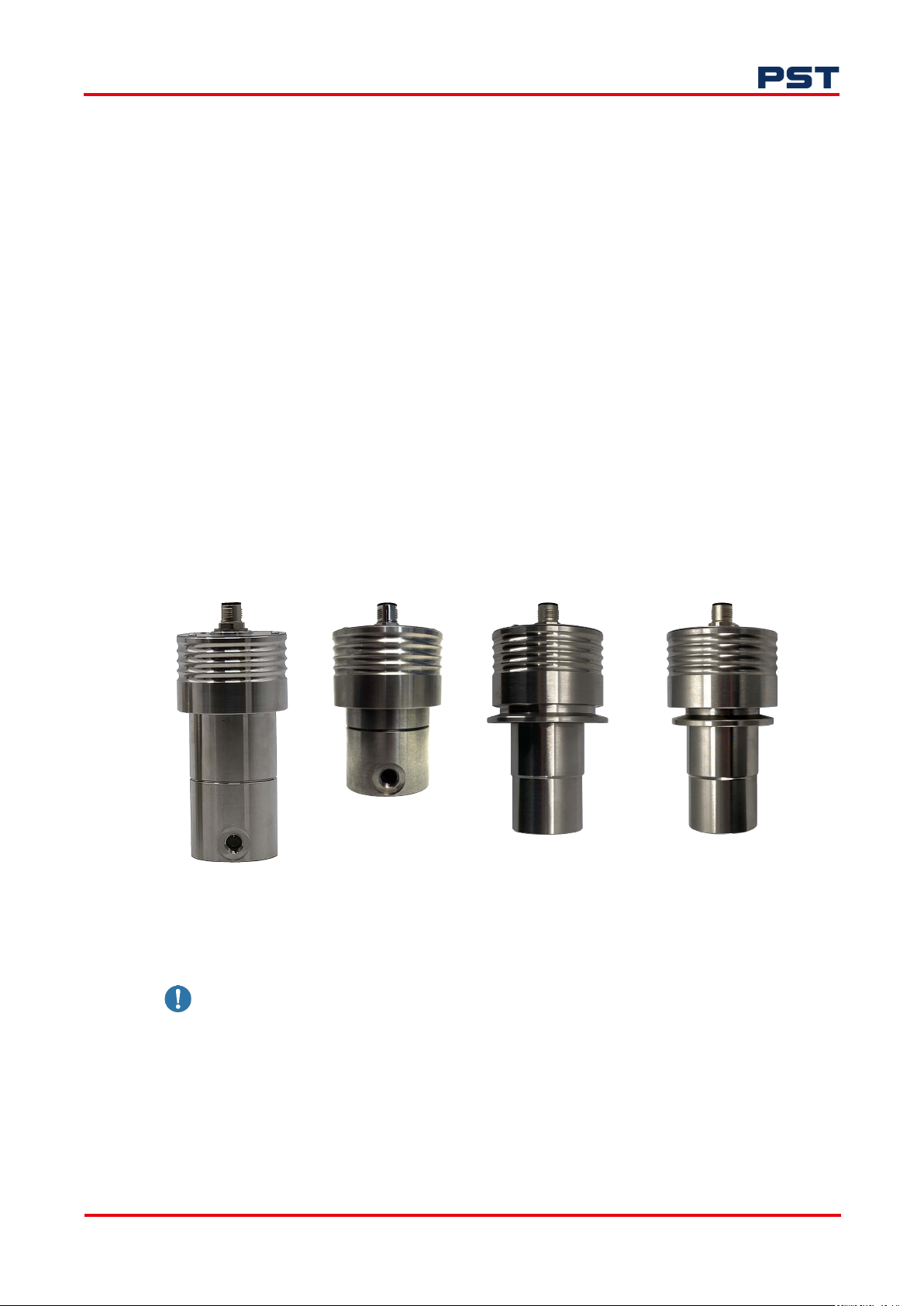
This manual is applicable to Minox i oxygen transmitter with electrochemical (EC) or solid-state
(S-S) sensors; and KF40 flange, flow-through or 2” tri-clamp process connections.
1.1 Overview
ATEX, IECEx-certified and UKCA compliant, the Minox i is an intrinsically safe (I.S), 2-wire, loop-powered oxygen transmitter with a 4...20 mA output. It is designed with proven sensor technology to
accurately measure O
ronments.
Minox i has a small footprint and offers a variety of process connections for oxygen measurement.
With an industry standard electrical plug, this compact transmitter can be installed in any OEM application simply and cost-effectively.
Minox i is available with the process connections shown below.
NOTE: You must provide suitable mating flange and clamp for KF40 and 2” tri-clamp connections.
in a variety of gases, in the most demanding applications and hazardous envi-
2
Flow-through (%)
Flow-through (ppm)
2” Tri-clamp
KF40 flange
Figure 1. Process connections for Minox i
Minox i can be used with a Programmable Logic Controller (PLC) or suitable equipment capable of
providing a 4...20 mA loop-power interface. For operation in hazardous Ex-rated areas, the interface
must be provided via a suitable isolation barrier device.
The Minox i oxygen transmitter must only be operated in the way set out in this user manual.
Always verify electrical interface circuit compatibility before connection.
ProcessSensing.com 1
Page 8
1.2 Components
The Minox i oxygen transmitter consists of an oxygen sensor and inbuilt microprocessor. They are
encased in stainless steel, with a process connection on the removable housing and an electrical signal
connector on the main housing.
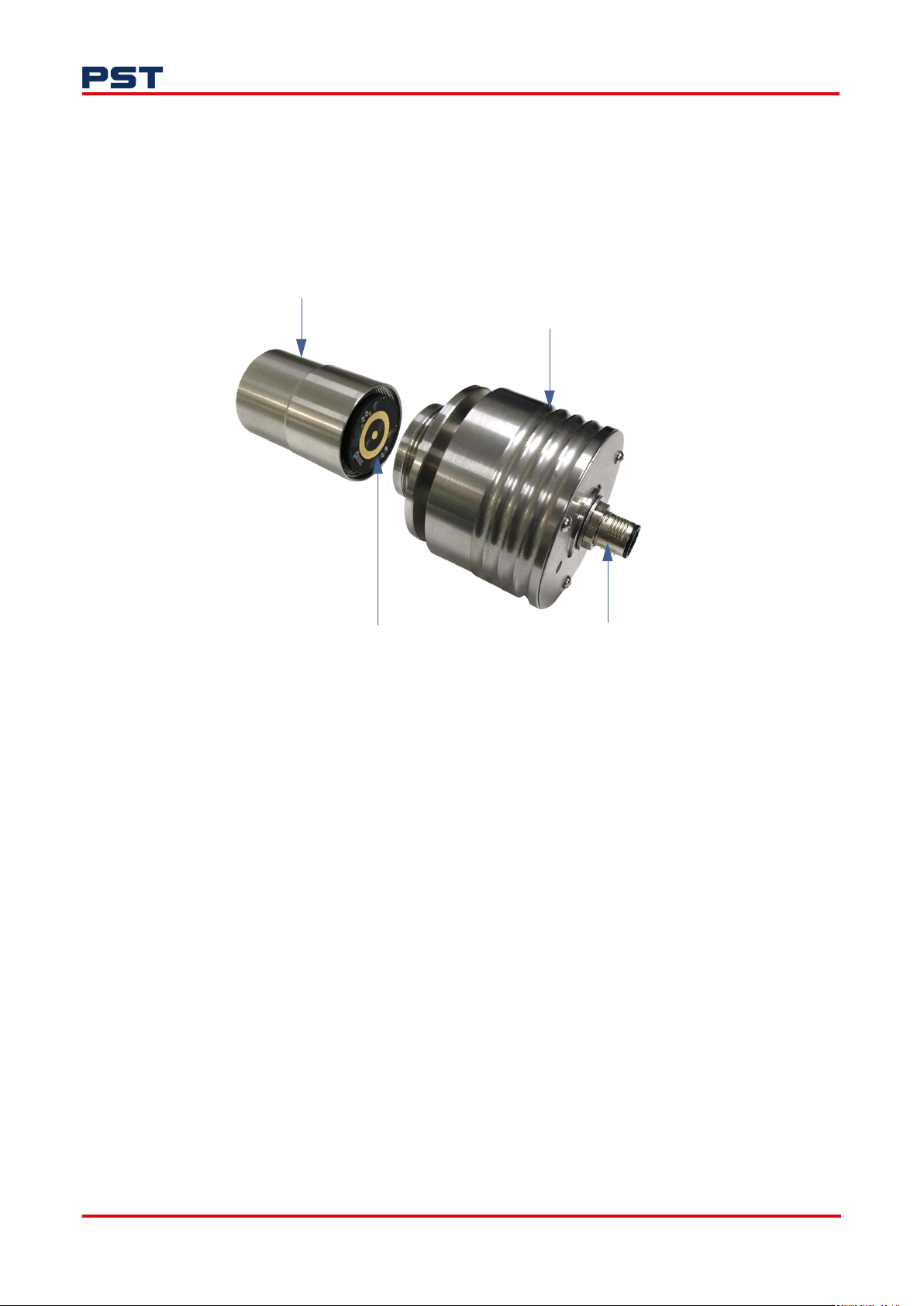
The sensor is replaceable and can be accessed via the removable housing, as shown in Figure 2:
Removable housing
Minox i Oxygen Transmitter User Manual
Main housing
Oxygen sensor
Figure 2. Structure of Minox i with EC sensor (KF40 flange pictured)
1.3 Sensors
1.3.1 Electrochemical % (EC %)
The Minox i EC % oxygen sensor is a galvanic fuel cell capable of superior performance, accuracy, and
stability. Its operational life is typically up to 18 months in ambient air. The sensor is designed to be
unaffected by the presence of other background gases.
The Minox i is required to be mounted in a vertical orientation with the electrical signal connector at
the top. For gases with a composition of hydrocarbons and/or CO
used when % level O
1.3.2 Electrochemical ppm (EC ppm)
The Minox i can be specified with a choice of EC ppm oxygen sensors. Both are galvanic fuel cells with
different chemistry. With both EC ppm sensors, the Minox i must be mounted vertically with the electrical signal connector at the top.
measurements are required.
2
Electrical signal connector
, the solid-state sensor should be
2
The OC-60 sensor is the ppm version of the EC% and is suitable for inert, H
and He gases. The OC-
2
69 sensor is compatible with gases that have a hydrocarbon composition or CO2 element.
2 ProcessSensing.com
Page 9

Minox i Oxygen Transmitter User Manual
1.3.3 Solid-state (S-S)
The Minox i S-S sensor is not gas-dependent or specific, and offers a robust measurement capability
on process gas streams or in containment environments. It can operate with or without sample flow,
making it ideal for in-situ monitoring, and it is not orientation-specific.
With the tri-clamp and KF40 process connections, the Minox i can be mounted on a T-piece of pipeline or on the vertical panel of a containment system without concern. The transmitter provides a linear output with a sensitivity that is constant throughout its operating range.
1.4 Applications
Typically, the intrinsically safe Minox i oxygen transmitter can be used in the following applications:
• Inerting
• Hydrogen and nitrogen gas generation
• Glove box and containment solutions
• Sieving and powder transfer systems (PTS)
• Additive Manufacturing
• Biogas and biomethane
• Pharmaceutical.
ProcessSensing.com 3
Page 10
2 Installation
Before installing your Minox i oxygen transmitter, ensure that its specifications are suitable for the
process or pipeline where it will be installed.
See "2.2.1 KF40 flange and 2” tri-clamp process connections with dimensions" on page 5 or "2.2.2
Flow-through process connection with dimensions" on page 6 for more guidance.
This product is not approved for use in applications where the sample gas is greater than
21 % volume O
2.1 Unpack the Minox i
NOTE: The sensor is packed in a sealed package that has been purged to remove O2 from the
packed environment. It should not be removed from the package until the transmitter has been
installed at the measurement point and you are ready to perform measurements.
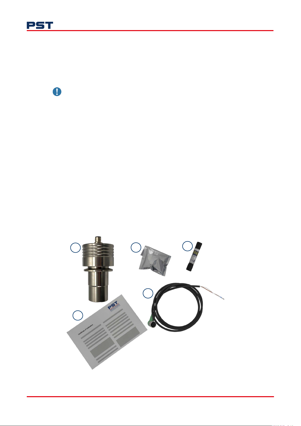
Your Minox i oxygen transmitter pack is comprised of the following equipment:
.
2
Minox i Oxygen Transmitter User Manual
1. Minox i oxygen transmitter
2. Electrochemical or solid-state oxygen sensor
3. A MagTip calibration tool
4. Certificate of calibration
5. Cable fitted with M12 connector.
1
2
5
4
3
Figure 3. Contents of Minox i package
4 ProcessSensing.com
Page 11
Minox i Oxygen Transmitter User Manual
Leaving a sensor in ambient air conditions will reduce sensor life.
2.2 Mount the Minox i
The Minox i transmitter requires a two-wire industry-standard 4...20 mA loop-powered connection,
which you must be provide. It must be installed in the measurement point before the sensor is
removed from its sealed package.
For flow-through connection, continue to "2.2.2 Flow-through process connection with dimensions"
on page 6.
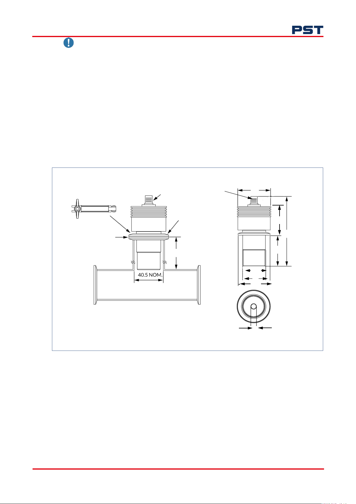
2.2.1 KF40 flange and 2” tri-clamp process connections with dimensions
A suitable mating flange and seal/centering ringwill be required to install the KF40 flange or tri-clamp
Minox i. These are not included in the pack.
Dimensions are in mm unless otherwise stated.
Electrical signal connector
Flange clamp
59
Tri-clamp vacuum
flange fitting
Seal/centering ring
53*
Ø37
39
54.8
Tri-clamp base and pipe T-piece
*Height to suit depth of sensor
BSPP 1/8 threaded
Figure 4. Technical drawing of 2” tri-clamp flange and KF40 process connections
1. Place the seal/centering ring on the pipe where the Minox i will be installed.
2. Put the process connection end of the Minox i into the pipe.
47.7
118.4
55
10
3. Place your flange clamp or tri-clamp over the seal/centering ring and the Minox i where they
meet the pipe.
4. Fasten the flange or tri-clamp until finger-tight.
5. Continue to "2.2.3 Electrical connection" on page 7.
ProcessSensing.com 5
Page 12
2.2.2 Flow-through process connection with dimensions
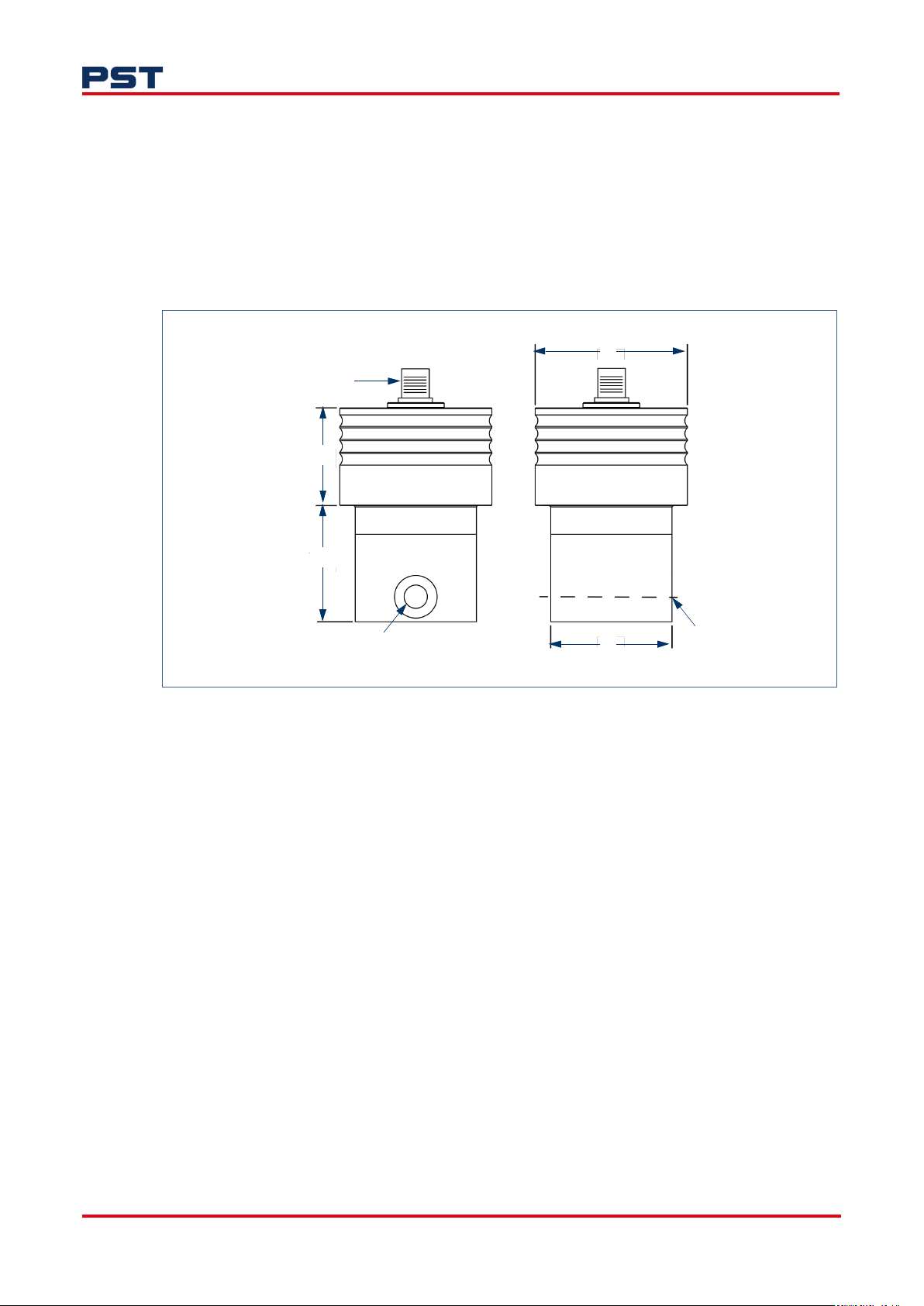
The flow-through Minox i is designed for measurement on an extracted sample gas. The sample gas
should be at atmospheric pressure +/- 100 mbar, and a flow-rate of 250...500 ml (0.5...1.0 SCFH) is
required.
If the sample gas is at a pressure regulator, a flow-meter must be placed before the transmitter. The
transmitter must be able to vent the gas to atmosphere or an atmospheric vent.
If the sample gas is at sub-atmospheric pressure, the sample must be drawn through the flow-through
block. PST-Ntron can supply systems to aid this installation upon request.
Electrical signal connector
38
Minox i Oxygen Transmitter User Manual
59
45.1
1/8” NPT
End elevation rotated 90
o
Figure 5. Technical drawing of flow-through process connection
1. Align the flow-through Minox i 1/8” NPT with your pipe fitting.
2. Fasten screws to adapt to pipe fitting.
47
1/8 “ NPT
6 ProcessSensing.com
Page 13
Minox i Oxygen Transmitter User Manual
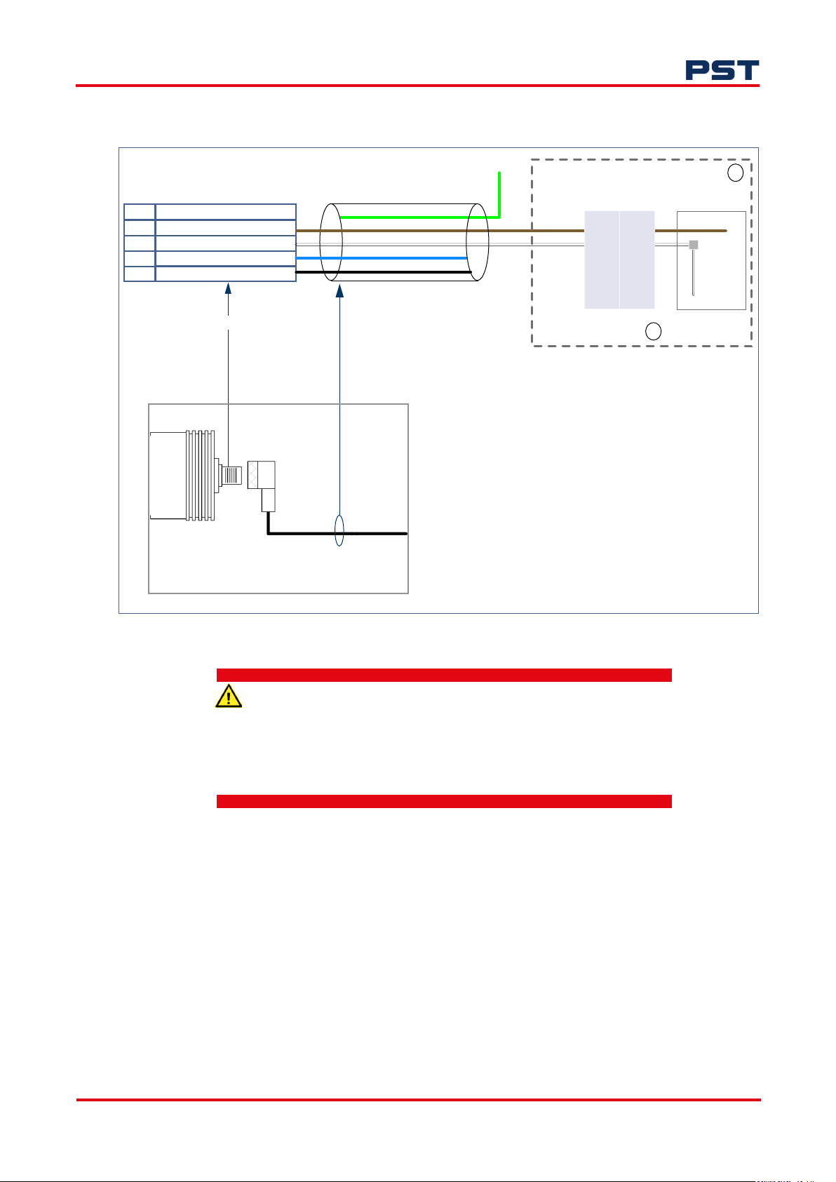
2.2.3 Electrical connection
2
Pin
Function
1
+24 V DC (loop in)
2
-VE (loop out signal)
No connection
3
No connection
4
M12 connector on Minox i
Minox i
Green
Brown
White
#Blue
#Black
# Additional cores/colors available
when standard 4-core cable supplied
with the Minox i
(right-angled or straight)
Cable
with M12 mating connector
Suitable isolation
barrier
+
-
non
I.S.
I.S.
output
output
+
-
1
Suitable
PLC / loop supply
+24 V
Loop
sensing
element
0 V
NOTE:
1. The above equipment to be supplied by
customer.
2. A suitable 4...20 mA loop-power source/
measurement circuit is required.
A typical representation is shown above.
Figure 6. Typical connection cable wiring
A suitable galvanic isolation barrier is required if the Minox i is
located in an Ex area.
Consult the EC-type examination certificate Baseefa19atex0200 for
Parameter Matching.
ProcessSensing.com 7
Page 14

The Minox i oxygen transmitter operates using a 2-wire industry-standard 4...20 mA loop-powered
supply which you must provide.
Once the Minox i is connected to your process, it is ready to be connected to your power supply. To
do this:
1. Align the pins in the Minox i electrical signal connector with the M12 mating connector on the
cable.
The cable connector can then be gently pushed into place.
2. Rotate the fastener clockwise until finger tight. Your Minox i oxygen transmitter is now con-
nected. A pulsing red LED will indicate it is operating correctly.
2.2.4 Install your sensor
The sensor supplied should only be removed from the sealed package when the transmitter is installed
and ready to make a measurement.
Minox i Oxygen Transmitter User Manual
Installing the sensor is straightforward, but should be done quickly to limit exposure to ambient O
levels, this is particularly important for the EC ppm sensors. Prolonged exposure to air will shorten the
operational life of the sensor.
As a guideline, you should install the sensor into the Minox i, and the mount the transmitter in the
measurement environment in 15-30 seconds. To install the sensor, please see "4.2 Replace the sensor" on page 13.
2
8 ProcessSensing.com
Page 15

Minox i Oxygen Transmitter User Manual
3 Calibration
NOTE: Calibration should be carried out by an appropriately trained or suitably qualified person.
The oxygen sensor output will decrease over time, and periodic calibration will be required. This is a
non-intrusive procedure, achieved by using the MagTip one-touch calibration tool included with your
Minox i.
Calibration cycles for the Minox i depend on the application, the applied gases, and the sensor type.
They can be carried out in-situ or after safely removing the oxygen transmitter from your process in a
bench test.
NOTE: For optimal calibration, the atmosphere surrounding the sensor must be ambient air (20.9 %
volume O
flushing the system with clean, oil-free compressed air.
The Minox i ppm must be calibrated in a controlled environment. Calibrating the Minox i % in
ambient air will significantly reduce sensor life.
When the MagTip tool is applied, the indicator LED will flash six times in rapid succession. This confirms calibration is in progress.
) with no contaminants present. This can be achieved using an oxygen analyzer or by
2
During normal operation, the indicator LED will flash once every two seconds. This slower flash confirms Minox i is powered up and operational.
NOTE: The number of times the indicator LED flashes will vary on earlier models of Minox i.
ProcessSensing.com 9
Page 16
3.1 In-situ
3.1.1 Minox i %
Please read the information on the previous page before proceeding.
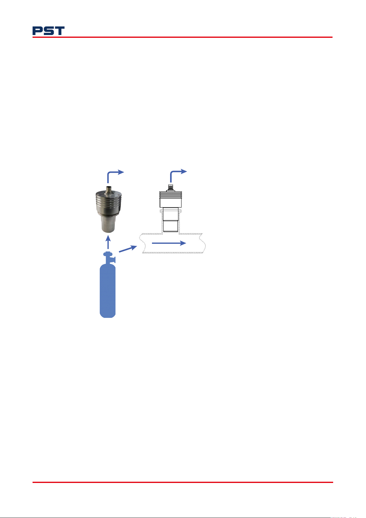
The Calibration gas used should match the gas concentration that was used during the factory calibration. The recommended gas concentration can be found on the calibration certificate that was
supplied with the transmitter.
1. Apply the calibration gas for a minimum of 15 minutes.
NOTE: The pressure flow should replicate that applied to the Minox i during normal operation. This
will ensure calibration is accurate, and avoid over-pressurizing the oxygen sensor.
Minox i Oxygen Transmitter User Manual
To customer control
system interface
Typical in-situ pipeline
calibration application
Cylinder oxygen (20.9%)
or ambient air
O
²
Figure 7. Calibration for Minox i %
2. Allow one to two minutes for the output to stabilize (i.e reach its ambient air concentration value
and remain at the value). An independent portable oxygen analyzer can be used to check this.
3. Observe the O
volume O
4. Place the MagTip on the Minox i main housing, adjacent to the red indicator LED, as shown in
Figure 8.
concentration on your oxygen analyzer display. It should read 20.9 %
2
.
2
10 ProcessSensing.com
Page 17

Minox i Oxygen Transmitter User Manual
The indicator LED will begin to flash rapidly.
Electrical signal cable
Indicator LED
Figure 8. Minox i with MagTip calibration tool
5. When calibration is complete, the indicator LED will resume flashing at a steady pulse.
For the standard 0...25 % O
17.376 mA.
This value, or the reading 20.9%, must be observed to confirm calibration is complete. When calibration is complete, the Minox i LED will resume flashing at a steady pulse.
MagTip calibration tool
range, the 4...20 mA output will be automatically adjusted to
2
3.1.2 Minox i ppm
Please read the information in "3 Calibration" on page 9 before proceeding.
The Calibration gas used should match the gas concentration that was used during the factory calibration. The recommended gas concentration can be found on the calibration certificate that was
supplied with the transmitter.
The pressure flow should replicate that applied to the Minox i during normal operation. This will
ensure calibration is accurate, and avoid over-pressurizing the oxygen sensor.
1. Apply the calibration gas until the reading stabilizes. Please allow a longer purge period to
achieve a lower oxygen reading, the table below can be used for guidance.
Reading
100 ppm 30 minutes
10 ppm 60 minutes
>10 ppm <60 minutes
Air to 0 ppm with N
purge
2
Recovery time
ProcessSensing.com 11
Page 18
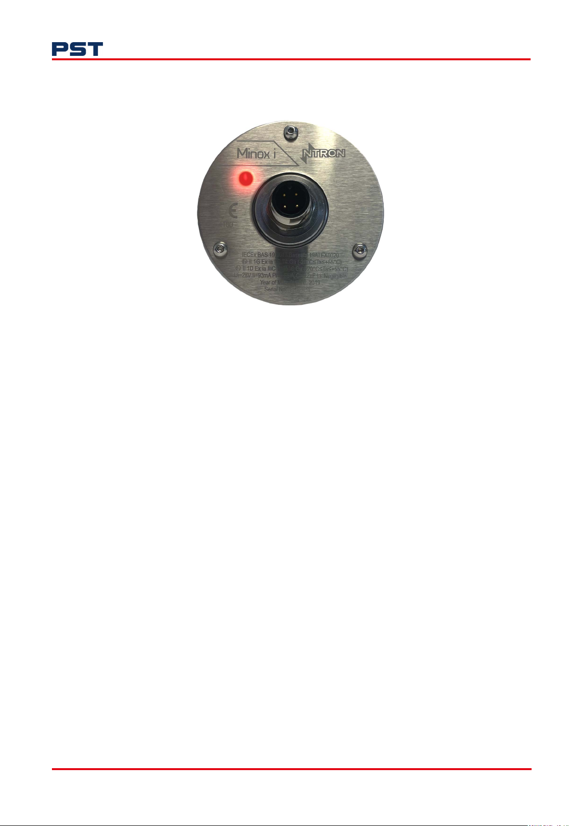
3.2 Air calibration
The following method of air calibration should only be performed on a Minox i %.
Minox i Oxygen Transmitter User Manual
Figure 9. Minox i indicator LED
1. Unfasten and remove the Minox i from your process, and leave it in an ambient air environment.
Ensure the environment has normal oxygen concentration, an independent portable oxygen analyzer can be used to check this.
2. Observe the O
bilized it should read 20.9 % volume O
concentration on your oxygen analyzer display. When the concentration has sta-
2
.
2
This usually takes between five and ten minutes.
3. Place the MagTip on the Minox i main housing, adjacent to the indicator LED, as shown in Figure
8. The red indicator LED will begin to flash rapidly.
4. When calibration is complete, the indicator LED will resume flashing at a steady pulse.
5. Re-install your Minox i following the instructions "2.2.1 KF40 flange and 2” tri-clamp process
connections with dimensions" on page 5 or "2.2.2 Flow-through process connection with dimensions" on page 6, depending on your process connection.
12 ProcessSensing.com
Page 19
Minox i Oxygen Transmitter User Manual
4 Maintenance
4.1 General
To maintain performance, the sensor in Minox i will require replacement. Please check the Technical
Specifications for frequency. During sensor replacement, it is recommended that light cleaning of the
external housing is carried out, as well as the checks outlined in this section.
Never use chemical cleaning agents or high pressure water or steam to clean the equipment. Do
not submerge in water.
4.2 Replace the sensor
The Minox i oxygen sensor is replaceable. When it reaches the end of serviceable life, calibration can
no longer be performed and the sensor must be replaced.
A regular program of calibration will mitigate against sudden sensor failure. It is advisable to establish
a program of preventative maintenance to ensure process downtime is kept to a minimum or avoided.
The sensor supplied should only be removed from the sealed package when the transmitter is
installed and ready to make a measurement.
Installing the sensor is straightforward, but should be done quickly to limit exposure to ambient O
levels, this is particularly important for the EC ppm sensors. Prolonged exposure to air will shorten the
operational life of the sensor.
As a guideline, you should install the sensor into the Minox i, and the mount the transmitter in the
measurement environment in 15-30 seconds.
To replace your sensor:
1. Unscrew the removable housing from the main housing of Minox i by turning it clockwise.
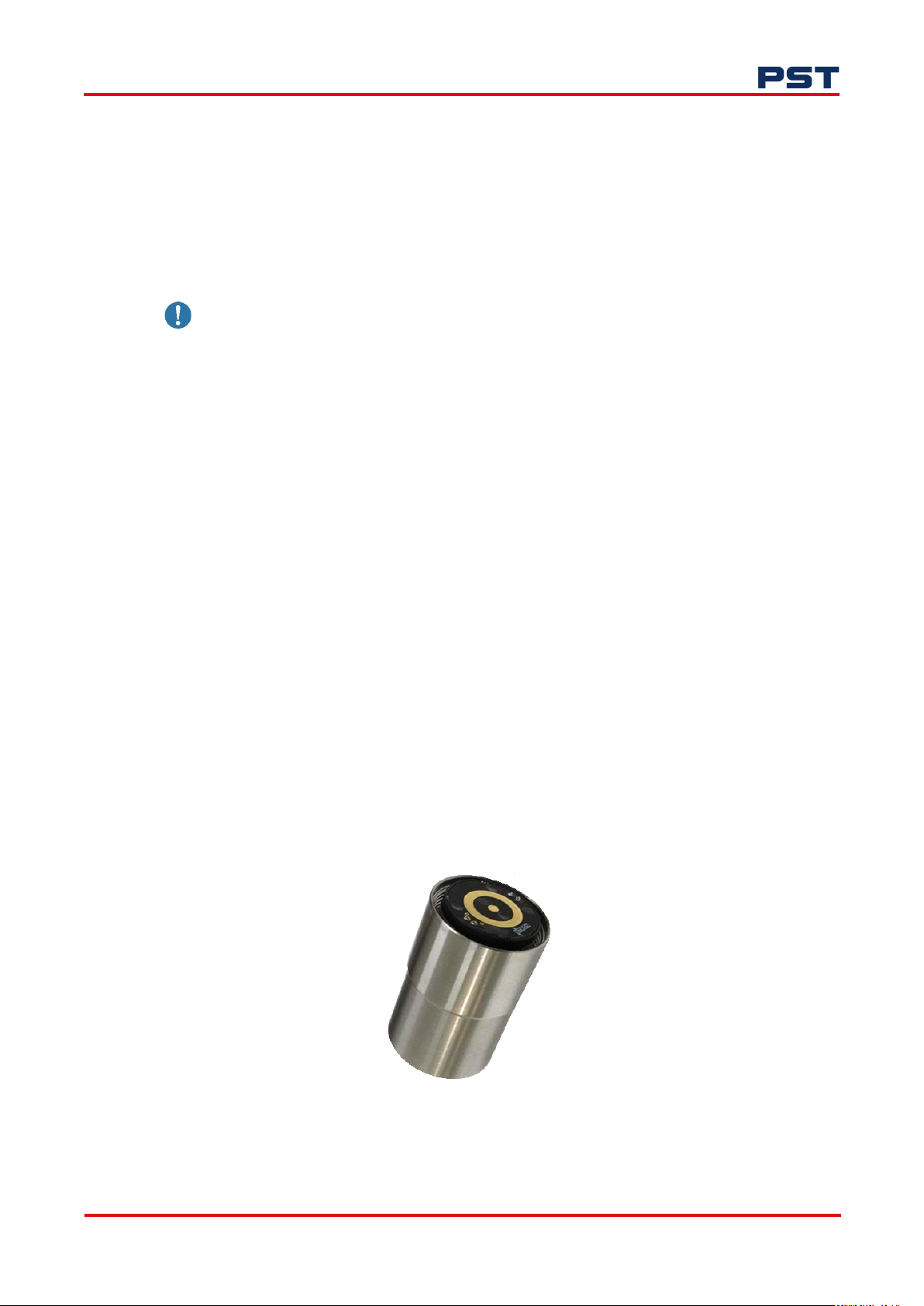
The sensor will be located in the removable housing, as shown.
2. Gently tip the sensor out of the removable housing into your hand or onto a soft surface.
2
Figure 10. Oxygen sensor placement in removable housing
3. Place your new EC or S-S oxygen sensor into the removable housing, ensuring the sensor’s brass
ProcessSensing.com 13
Page 20

rings are facing out of the removable housing as shown in Figure 10.
4. Screw the removable housing back onto the main housing, by turning it counter-clockwise.
NOTE: The brass slip rings on the sensor must face into the main housing and out of the removable
housing as shown above.
4.3 Check your Minox i
The following checks will ensure your Minox i oxygen transmitter is operating as its optimum.
• Check for any damage to the connecting cable
• Depending on process conditions and location, check the gas entry orifice at the face-end of the
Minox i.
This is to ensure there is no build-up of particulate matter, and that moisture is not being retained
at the orifice.
Typically, the Minox i will require removal from the process to carry out checks, cleaning and sensor
replacement.
Minox i Oxygen Transmitter User Manual
4.4 Operational spares
The only replaceable part for Minox i is the sensor. Sensor model details can be found in "Appendix A
- Technical Specifications" on page 15.
The replacement sensor must be the same as the installed sensor, for example, it is not possible to
replace an OC-90 EC sensor with an OC-60 EC sensor.
NOTE: The sensors have a shelf life. Please see "Appendix A - Technical Specifications" on page 15
for details.
14 ProcessSensing.com
Page 21
Minox i Oxygen Transmitter User Manual
5 Appendices
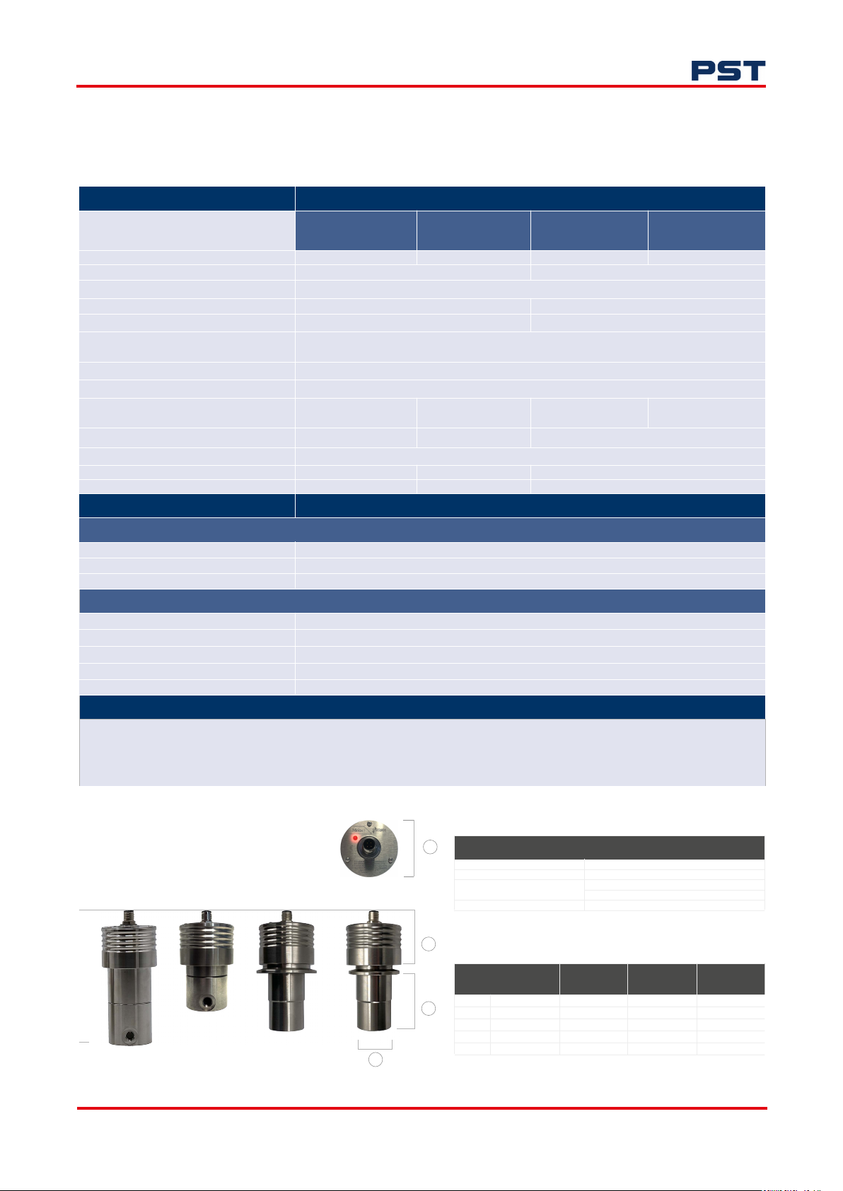
Appendix A - Technical Specifications
Sensor
Solid-state Electrochemical
(%)
Model OC-92 OC-90 OC-60 OC-69
Measuring Range 0…25 % 0…10, 0…100, 0…1000 ppm
Accuracy Please see Accuracy Table below
Output Resolution (4...20 mA) 0.01 % 1 ppm
Lower Detection Limit (LDL) 0.05 % 1 ppm
Sample Flow Rate (application dependent) Flow-through / extractive: 100...500 ml/min (250 ml/min optimal) in a vented atmosphere
Pressure Range 900…1100 mBar
Response Time (T90) < 15 seconds @ 25 °C (77 °F) within selected range
Operating Temperature Range -20…+50 °C
(-4…+122 °F)
Life Expectancy (application dependent) Up to 2 years Up to 18 months Up to 12 months
Humidity 0…95 %rh non-condensing (with normal use)
Shelf Life Up to 12 months Up to 6 months Up to 3 months
Calibration Interval (application dependent) 6 months 6 months 3...6 months
Direct insertion: Up to 6 m/s
+5…+45 °C
(+31…+113 °F)
Transmitter
Electrical
Output Signal 4…20 mA loop-powered
Electrical Interface Industry standard M12
Power Supply 24 V DC +/- 10 % (a suitable I.S barrier is required)
Mechanical
Ingress Protection IP66 (NEMA4)
Housing Material 316 Stainless steel
Process Connection Flow-through (1/8” NPT), KF40 flange, Tri-clamp
Gas-wetted Materials 316 Stainless steel
O-ring Material Nitrile
Hazardous Area Classification
IECEx: Ex ia IIC T4 Ga (-20°C ≤ Ta ≤ +55°C)
ATEX: Ex ia IIC T4 Ga (-20°C ≤ Ta ≤ +55°C), Ex ia IIIC T
cQPSus: Class 1 Zone 0 AEx ia IIC T4 Ga, Class 1 Zone 20 AEx ia IIC T135°C Da
UKEX, and JPN Ex: Ex ia IIC T4 Ga (-20°C ≤ Ta ≤ +55°C), Ex ia IIC T
135°C Da (-20°C ≤ Ta ≤+55°C)
200
135°C Da (-20°C ≤ Ta ≤+55°C)
200
Electrochemical
(ppm)
abs
+5…+45 °C
(+31…+113 °F)
Electrochemical
(CO
gases, ppm)
2
V
V
V
-10…+45 °C
(+14…+113 °F)
Accuracy Table
Accuracy at standard temperature and pressure (STP)
a
Range
10 ppm +/- 0.5 ppm
100 ppm +/- 1 ppm
Flow-through (%)
Flow-through (ppm)
Tri-clamp
KF40
d
ProcessSensing.com 15
1000 ppm +/- 3 ppm @ 100 ppm
25 % +/- 0.03 % @ 1 %
b
Dimensions (mm)
Flow-through
(%)
a
c
b
c
d
e
59 59 59 59
54 54 54 54
- - 55 55
47 47 37 37
129 100 118 118
+/- 1 ppm @ 10 ppm
Flow-through
(ppm)
Tri-clamp KF40
Page 22
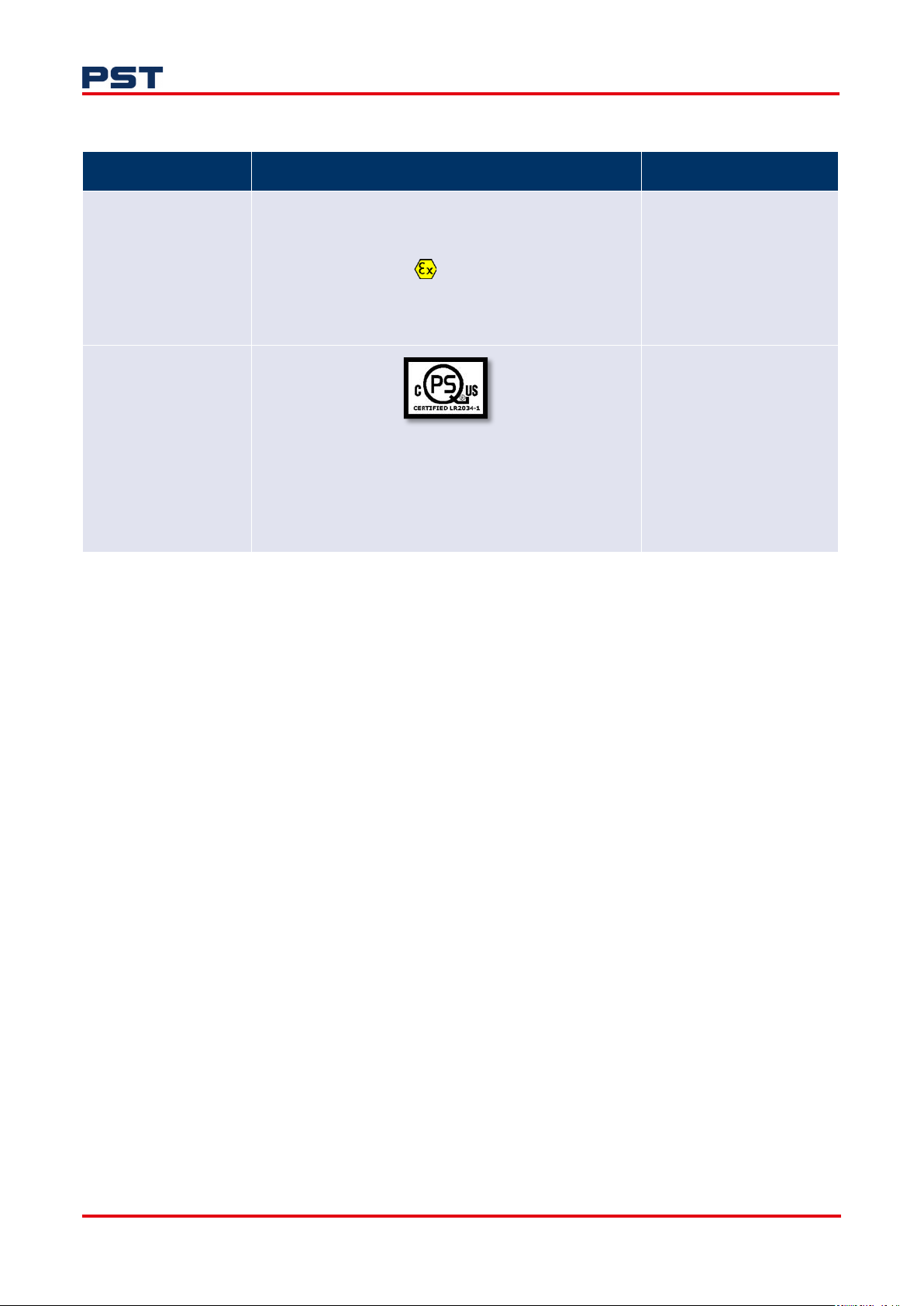
Appendix B - Hazardous Area Certification
Region Certification details Standards
Minox i Oxygen Transmitter User Manual
Europe
&
Japan
North America/Canada
IECEx / ATEX / UKCA
IECEx BAS 19.0013 / Baseefa 19ATEX0020 /
BAS22UKEX0052
II 1 GD
Ex ia IIC T4 Ga (-20 °C≤Ta≤+55 °C)
Ex ia IIC
Ui=28 V Ii=93 mA Pi=0.65 W Ci=12nF Li=705uH
Class II Division 1 Groups E-G T135°C
Class I Zone 0 AEx ia IIC T4 Ga / Ex ia IIC T4 Ga
Class 1 Zone 20 AEx ia IIC T135°C Da / Ex ia IIC T135°C Da
Ui/Vmax=28 V Ii/Imax=93 mA Pi=0.65 W Ci=12nF Li=705uH
135°C Da (-20 °C≤Ta≤+55 °C)
T200
Class I Division 1 Group A-D T4
Ta = -20°C≤Ta≤+55°C
EN IEC 60079-0:2018
EN 60079-11:2012
IEC 60079-0 ed. 7 2017
IEC 60079-11 ed. 6 2011
CSA C22.2 No. 60079-0-19
CSA C22.2 No. 60079-11-
14
UL 60079-0-7th ed.
UL 60079-11-6th ed.
16 ProcessSensing.com
Page 23

Minox i Oxygen Transmitter User Manual
Appendix C - Quality, recycling and warranty information
Ntron Gas Measurement is part of the Process Sensing Technologies (PST) Group. The PST
Oxygen group of companies - Aii, Ntron and SST - comply with applicable national and
international standards and directives.
Full information can be found on this website
https://www.processsensing.com/en-us/resources/compliance/
The compliance site contains information on the following directives:
• ATEX (equipment for explosive atmosphere, Europe)
• CE
• ETL (The ETL mark is proof of product compliance to North American safety
standards
• IECEx
• REACH (Registration, Evaluation, Authorization, and Restriction of Chemicals)
• Recycling policy
• RoHS (Restriction of Hazardous Substances in electrical and electronic equipment
• UKCA
• WEEE (Waste Electrical and Electronic Equipment recycling.
ProcessSensing.com 17
Page 24

©2024 Process Sensing Technologies plc
 Loading...