

Page 1

MDS8PT
Universal Temperature & Process
Benchtop Meter with Alarms
Page 2

omega.com [email protected]
Servicing North America:
U.S.A. Omega Engineering, Inc.
Toll-Free: 1-800-826-6342 (USA & Canada only)
Customer Service: 1-800-622-2378 (USA & Canada only)
Engineering Service: 1-800-872-9436 (USA & Canada only)
Tel: (203) 359-1660 Fax: (203) 359-7700
e-mail: [email protected]
For Other Locations Visit omega.com/worldwide
PROPRIETARY STATEMENT - This manual contains proprietary design information representing Omega Engineering Inc. It is intended solely for the
Information and use of parties operating and maintaining the equipment described herein. Such proprietary information may not be used, reproduced, or
disclosed to any other parties for any other purpose without the expressed written permission of Omega Inc.
Page 3

TABLE OF CONTENTS
SECTION 1 INTRODUCTION
1.1 Safety and Precautions ........................................................................................ 1
1.2 Cautions and IEC Symbols .................................................................................. 1
1.3 Statement on Marking ................................................................................ 2
1.4 Available Models .................................................................................................. 2
1.5. Communication .................................................................................................... 2
1.6 Reference Manuals .............................................................................................. 2
SECTION 2 UNPACKING
2.1 Inspection ............................................................................................................. 3
2.2 Power Cords ......................................................................................................... 4
SECTION 3 HARDWARE SETUP
3.1 MDS8PT Front Panel ........................................................................................... 5
3.1.1 ..10-Pin Connector ............................................................................................ 6
3.1.2 ..RTD Wiring Diagram Connector ...................................................................... 7
3.1.3 ..Process Current Wiring Diagram ..................................................................... 7
3.1.4 ..Universal Thermocouple Connector ................................................................ 8
3.2 MDS8PT Rear Panel ............................................................................................ 9
3.2.1 .. Screw Terminals ........................................................................................... 10
SECTION 4 CONFIGURATION AND PROGRAMMING
4.1 Controls ............................................................................................................... 11
4.2 Menu Structure ................................................................................................... 12
4.3 Selecting an Input ............................................................................................... 13
4.4 AlarmConguration(PRoG>ALM.#).................................................................14
4.4.1 .. Setting Alarm Type .........................................................................................14
4.4.2 .. SettingAlarmHigh/LowReferences.............................................................15
4.4.3 .. SettingtheAlarmColor(PRoG>ALM.#>A.CLR)........................................15
4.4.4 .. ActivatingaRelay(PRog>dtR#>Mode).....................................................15
4.5 Analog Output ......................................................................................................16
4.5.1 .. Select an Output Type ....................................................................................16
4.5.2 .. Set Mode to Retransmission ..........................................................................16
4.5.3 .. Set Scaling .....................................................................................................16
SECTION 5 SPECIFICATION
5.1 Approval Information ........................................................................................... 17
SECTION 6 MAINTENANCE .......................................................................................... 18
Page 4

TABLE OF FIGURES
Figure 1. Accessories Packaged with MDS8PT Unit ................................................... 3
Figure 2. MDS8PT Front Panel .................................................................................. 5
Figure 3. 10-Pin Connector Input Pin Assignments ..................................................... 6
Figure 4. RTD Wiring Diagram .................................................................................. 7
Figure 5. 4-20 mA Sensor Wiring Diagram ................................................................ 7
Figure 6. Mini/Standard Thermocouple ...................................................................... 8
Figure 7. MDS8PT Rear Panel .................................................................................. 9
Figure 8. Benchtop Meter Wiring Diagram ................................................................ 10
Figure9.MDS8PTLEDDisplay................................................................................11
Figure 10. Circular Flow of Menus ............................................................................... 12
Figure 11. Alarm Range Option Diagram ..............................................................,.... 14
Figure 12. Alarm Scaling Diagram .............................................................................. 16
TABLE OF TABLES
TABLES
Table 1. IEC Symbols .................................................................................................. 1
Table 2. Model Features................................................................................................ 2
Table 3. Supporting Documents .................................................................................. 2
Table 4. Package Contents .......................................................................................... 3
Table 5. Optional Power Cords .................................................................................... 4
Table6.FrontPanelComponentsList........................................................................ 5
Table 7. Sensor Inputs Assignments ........................................................................... 6
Table 8. Rear Panel Component locations .................................................................. 9
Table9.CongurationforTerminals...........................................................................10
Table 10. Selecting an Input ........................................................................................ 13
Table11.BenchtopMeterSpecicationsSummary....................................................17
Table 12. Fuses ............................................................................................................ 18
Page 5

SECTION 1 INTRODUCTION
The MDS8PT Platinum Series Universal Benchtop Digital Meter (Benchtop Meter), is ideal for
laboratory and other application uses requiring portable temperature or process measurement.
Itfeaturesauniversalinputconguredforusewithathermocouple,RTD,Thermistoror
Voltage/Currentsignal.TheBenchtopMeterisfactoryconguredandcalibratedforuseoutof
the box.
It is important to read and follow all precautions and instructions in this manual and other
referenced manuals, before operating or commissioning this device, as it contains important
information relating to safety and EMC.
1.1 Safety and Precautions
• Do not exceed the voltage rating.
• Always disconnect the power before changing the signal and power connections.
• Donotoperateinammableorexplosiveenvironments.
• Never operate with a power cord that is not properly rated for use with this unit.
• Remove and or disconnect main power cord before attempting any maintenance or
fuse replacement.
• Do not connect and/or operate this unit to a non-grounded or non-polarized outlet or
power source.
There are no user serviceable parts inside unit. Attempting to repair or
service unit may void the warranty.
This product is not designed for medical applications.
1.2 Cautions and IEC Symbols
This device is marked with international safety and hazard symbols shown in Table 1
below, in accordance with EN61010 3rd Edition 2012. It is important to read and follow
all precautions and instructions in this manual before operating or commissioning this
device as it contains important information relating to safety and EMC. Failure to follow
all safety precautions may result in injury and/or damage to the meter. Use of this device
inamannernotspeciedbythemanufacturermayimpairprotectiondevicesandsafety
features provided by the unit.
IEC SYMBOLS DESCRIPTION
Table 1. IEC Symbols
CAUTION, risk of electrical shock
CAUTION, refer to accompanying documents
1
Page 6

1.3 Statement on Marking
OMEGApolicyistocomplywithallworldwidesafetyandEMI/EMCregulationsthat
applytoCECerticationstandards,includingEMCDirective2014/30/EULVD(Safety)
Directive2014/35/EU,andEEERoHSIIDirective2011/65/EU.OMEGAisconstantly
pursuingcerticationofitsproductstotheEuropeanNewApproachDirectives.OMEGA
will add the markingtoeveryapplicabledeviceuponvericationofcompliance.
1.4 Available Models
The Universal Benchtop Meter has two available models with features as listed in Table 2.
Table 2. Model Features
Model Features
MDS8PT-330-C24-EIP Benchtop Meter
-EIP Ethernet
-C24 Isolated RS232 and RS485
-330 Dual Alarm Relays
-A Isolated Analog Output
MDS8PT-330 Benchtop Meter
-330 DualAlarmRelays(ONLY)
1.5. Communication
The Platinum Series Benchtop Meter uses a standard USB port compatible with the
OmegaPlatinumcongurationsoftware,availablefromtheOmega website; as well as
Optional serial and Ethernet connectivity manuals. All communication options support
both the Omega ASCII protocol, Modbus ASCII, Modbus RTU and Modbus TCP/IP.
Refer to Table 3 for supporting manuals.
1.6 Reference Manuals
Refer to these supporting documents for complete information about operation and
congurationoftheBenchtopMeter.
Number Title
M5460 Platinum Series Temperature and Process Meters - User’s Manual
M5461
M5451
M5452
M5458
SoftwareConguration-User’sManual
Platinum Series Temperature and Process Controllers - User’s Manual
Serial Communication Protocol
Platinum Series User Manual - Modbus Interface
Table 3. Supporting Documentation
2
Page 7
SECTION 2 UNPACKING
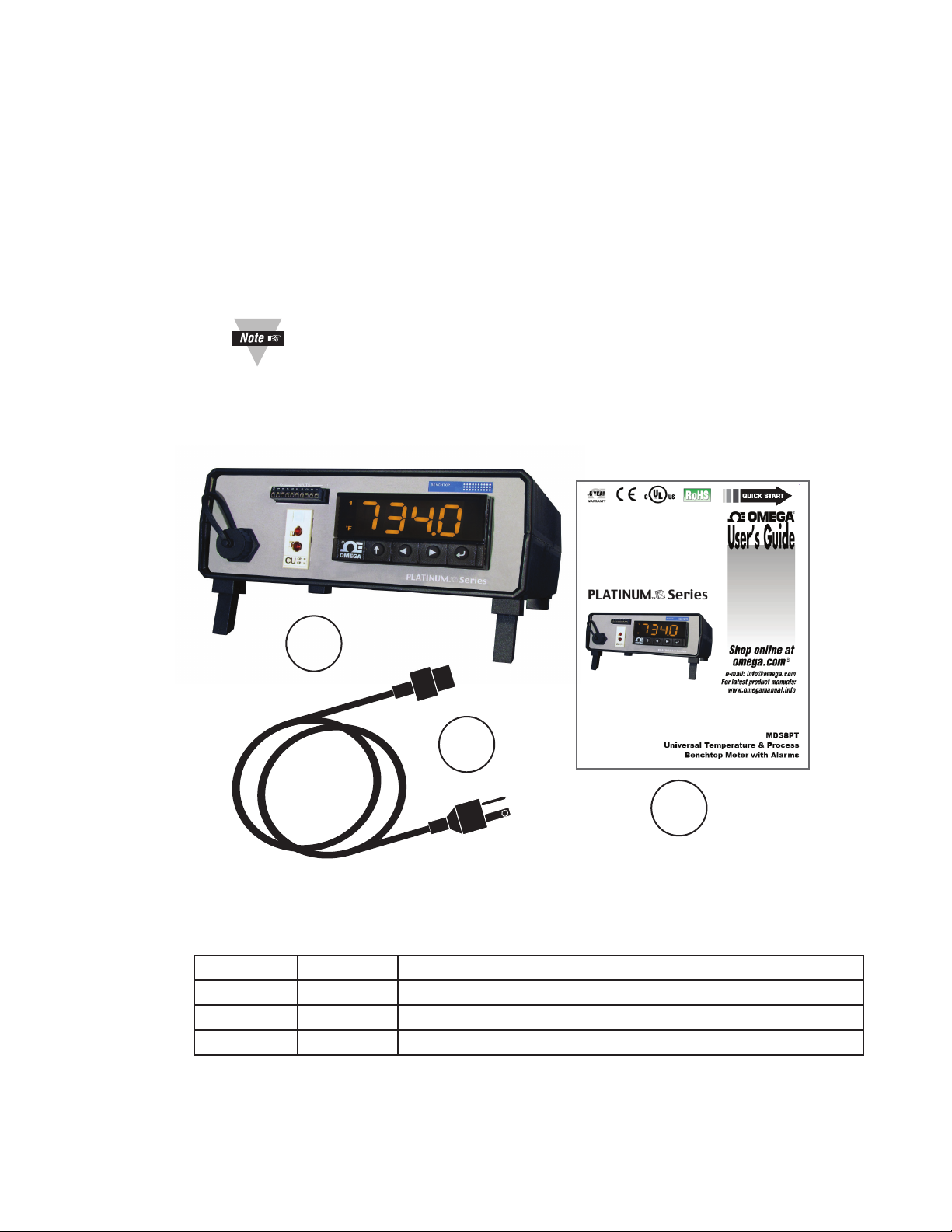
Read the packing list, it is important to verify all equipment shipped has been delivered as
shown in Figure 1 and Table 4. If there are any questions about the shipment please email or
call the Customer Service Department listed in this manual.
2.1 Inspection
Inspect the shipment container and equipment for any signs of damage. Record any
evidence of rough handling in transit and report any damage immediately to the shipping
agent.
Save packaging material and carton in the event that returns are necessary.
The carrier will not honor any damage claims unless all original shipping
material is saved for inspection.
1
2
3
Figure 1. Accessories Packaged with MDS8PT Unit.
Table 4. Packing Contents.
Item Name Description
1 Unit MDS8PT Universal Benchtop Digital Meter
2 Cord AC Power Cord (Refer to Table 5 on page 4)
3 Guide MQS5576(QuickStartGuide)
3
Page 8

2.2 Power Cords
Electrical power is delivered to the Benchtop Meter by an AC power cord to plug into the
IEC 60320 C-13 power socket located on the rear panel of the unit. Refer to Section 3.2
Figure 7 for detailed connections.
The input power is fused. Relay terminals must be limited to 30
VRMS and are fused on the common terminals.
The Benchtop Meter operates from 90 to 240 VAC, 50-60 Hz, 4W. A main power cord is
included at no charge with the order. Table 5 below, lists optional power cords.
Table 5. Optional Power Cords.
PWR Cord Type Part Number PWR Rating
United Kingdom, Ireland Power Cord-UK 240V
Denmark Power Cord-DM 230V, 16A
USA, Canada, Mexico Power Cord-Molded 120V
Italy Power Cord-IT 230V, 16A
Continental Europe Power Cord E-10A 240V, 10A
Europe Power Cord E-16A 240V, 16A
4
Page 9
CU
CP +
CP -
PLATINUMTM Series
BENCHTOP
10 INPUTS 1
10
9
8
7
6
5
4
3
2
1
SECTION 3 HARDWARE SETUP
ThehardwareconnectionsandcongurationtooperatetheUniversalBenchtopDigitalMeter.
3.1 MDS8PT Front Panel
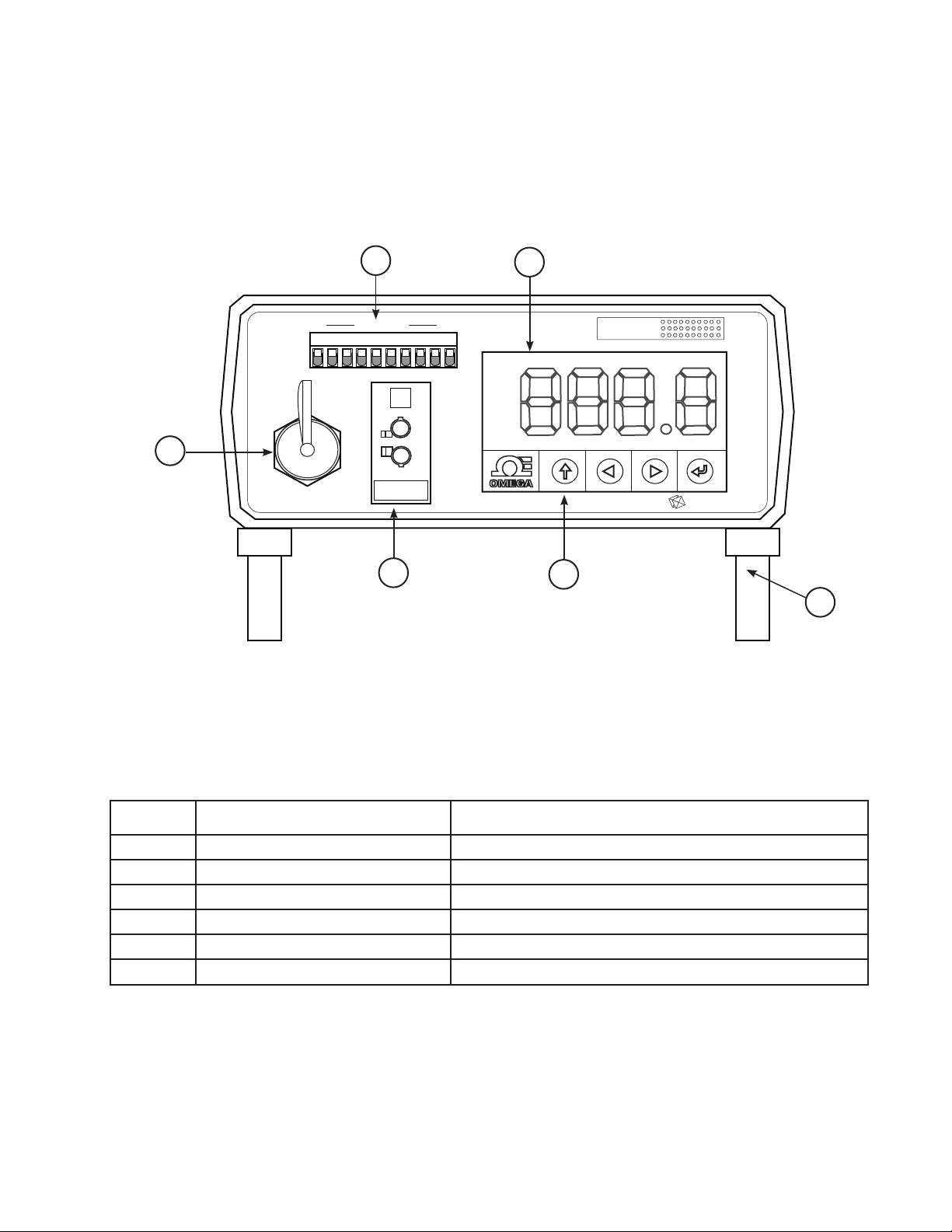
The controls, indicators and input connections of the Benchtop Meter
are shown in Figure 2.
1
2
6
5
4
Figure 2. MDS8PT Front Panel. (Not to scale)
Table 6. Front Panel Compnents List.
Item Name Description
1 10-Pin Input Connector Process RTD and Thermistor Inputs
2 Display - Meter/Alarm Four-digit,three-color,LEDDisplay
3 Adjustable Feet Adjusts viewing angle.
4 Push Buttons Menu navigation
5 Universal Panel Jack (UPJ) Thermocouple Input
6 USB Port USB Port, Type A Female
3
5
Page 10
3.1.1 10-Pin Connector
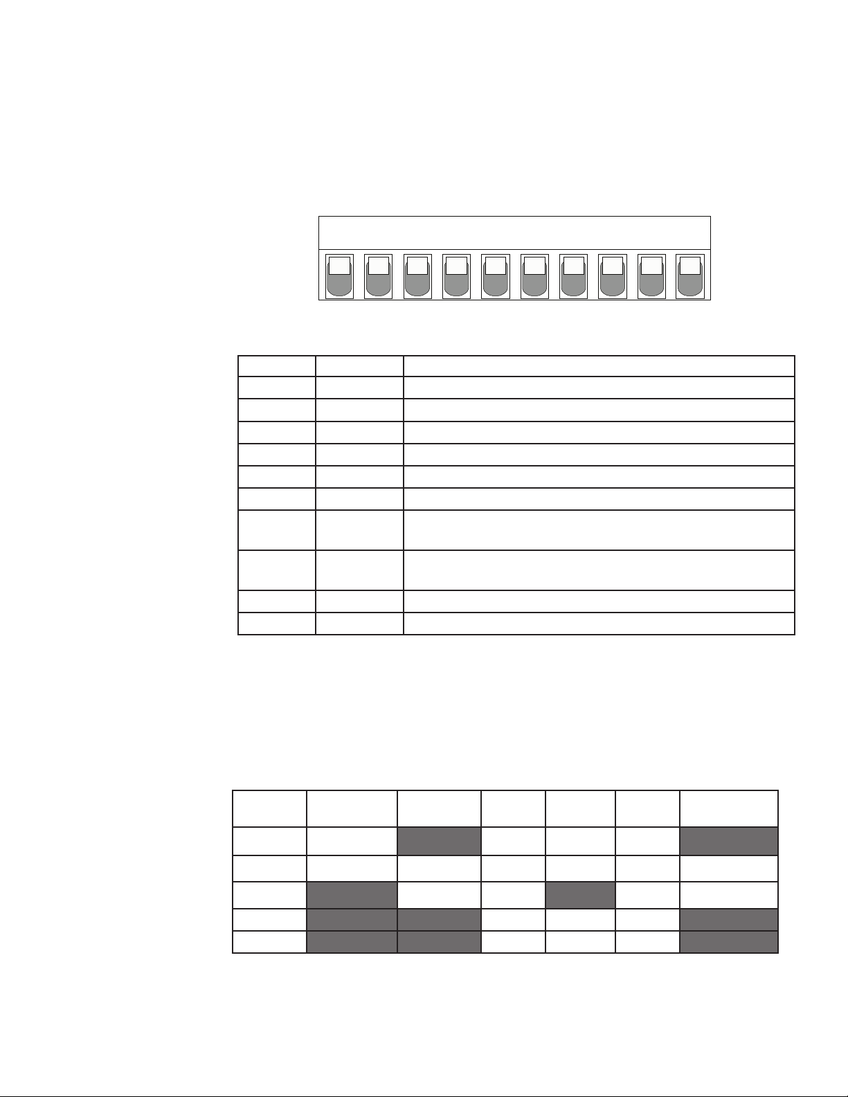
Figure 3 shows the10-pin connector with corresponding input pin assignments.
Sensorselectionisrmware-controlled,andnojumpersettingsarerequiredto
switch between different sensor types.
6
5
7
8
9
10
Figure 3. 10-Pin Connector Input Pin Assignments.
Pin No. Code Description
1 ARTN Analog return signal (analog ground) for sensors.
2 AIN+ Analog positive input
3 AIN- Analog negative input
4 APWR Analog power (Only used for 4-wire RTDs)
5 - - Not Used
6 EXCT ExcitationvoltageoutputreferencedtoISOGND
7 DIN Digitalinputsignal(latchreset),positiveat>2.5,Ref.to
ISOGND
8 ISOGND Isolated ground for serial communications, excitation,
and digital input
9 RX/A Serial communications receive
10 TX/B Serial communications transmit
4
3
2
1
Table 7 summarizes the universal input pin assignments for different sensor
inputs. Refer to Section 5-CongurationandProgramming,fordetailsto
program the unit for desired sensor settings.
Table 7. Sensor Inputs Assignments.
Pin
Number
1 Rtn ** RTD2- RTD2+
2 Vin +/- I+ RTD1+ RTD1+ RTD1+ TH+
3 I- RTD2- TH-
4 RTD1- RTD1- RTD1-
** Requires external connections to Pin-4.
Process
Voltage
Process
Current
6
2-Wire
RTD
3-Wire
RTD
4-Wire
RTD
Thermistor
Page 11
3.1.2 RTD Wiring Diagram Connector
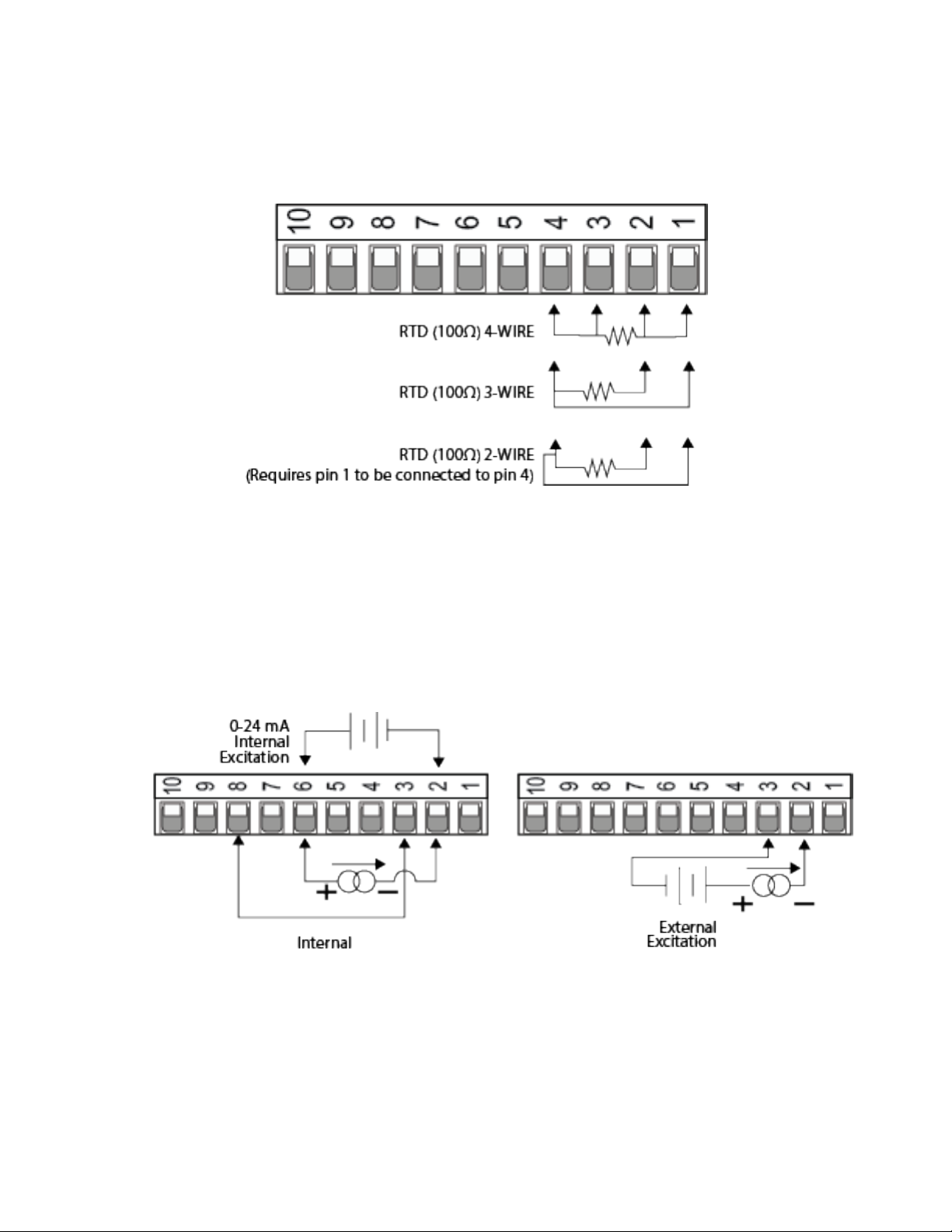
Figure 4 illustrates the wiring diagram for connecting a platinum RTD.
A two-wire RTD requires an external jumper from Pin 1 to Pin 4.
Figure 4. RTD Wiring Diagram.
3.1.3 Process Current Wiring Diagram
Figure 5 illustrates the wiring diagram for connecting 4-20mA Sensor using
internal or external excitation. Refer to M5460 Section 4 for details on setting up
internal excitation.
Figure 5. 4-20 mA Sensor Wiring Diagram.
7
Page 12
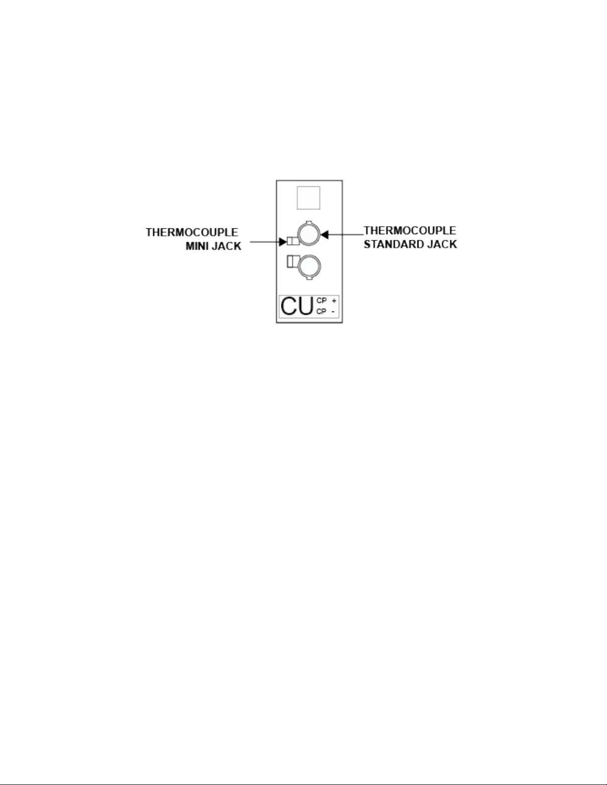
3.1.4 Universal Thermocouple Connector
The Benchtop Meter accepts both Mini and Standard thermocouple connectors
using the Universal Panel Jack shown in Figure 6. The Benchtop Meter has
internal cold junction compensation and is compatible with thermocouples listed
in Table 7 on page 6.
Figure 6. Mini/Standard Thermocouple.
8
Page 13
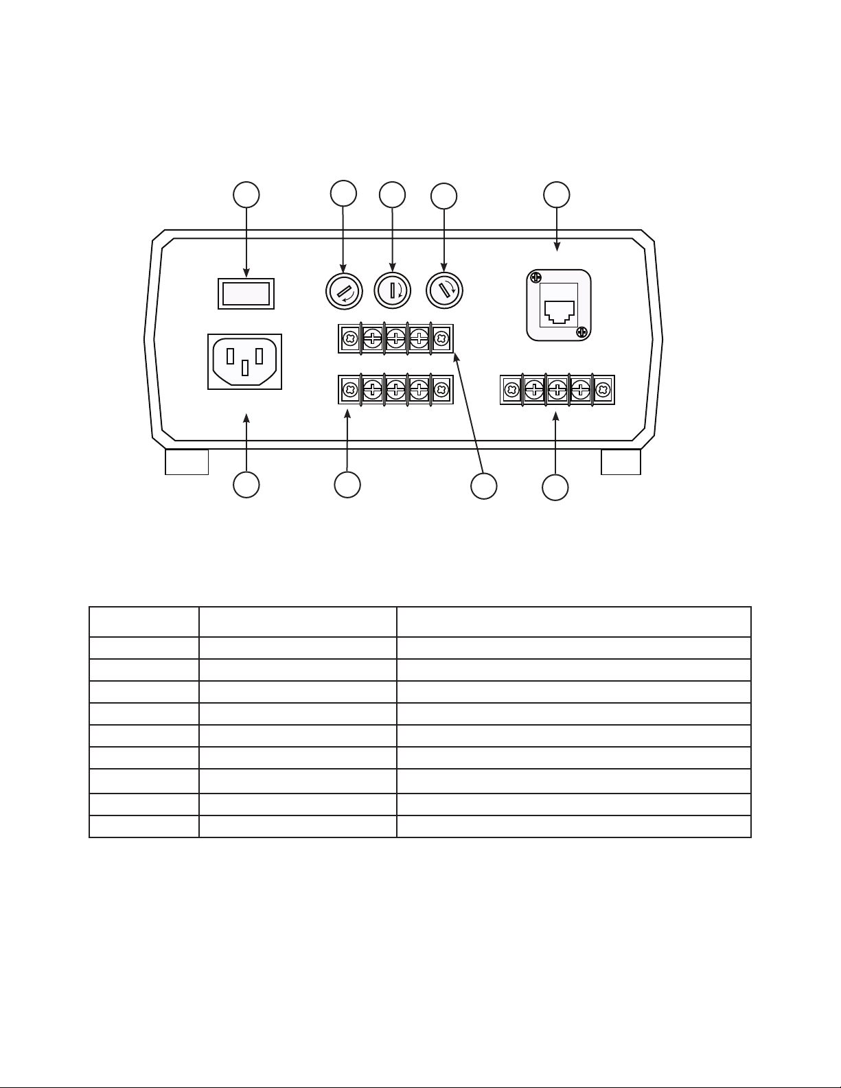
3.2 MDS8PT Rear Panel
The Rear Panel connections for the Benchtop Meter are shown in Figure 7 below.
1
O -
AC MAIN OUTPUT
90-240 VAC ~ 50 / 60 Hz
O / I
F1
ALARM1
ALARM2
2
E
S
U
F
89
3
F2
E
S
U
F
4
F3
E
S
U
F
7
5
ETHERNET
ISO ANALOG
6
Figure 7. MDS8PT Rear Panel. (Not to scale)
Table 8. Rear Panel Component locations.
Item Name Description
1 ON/OFF Switch Turns the unit on
2 F1 (Fuse) Protects the AC power input
3 F2 (Fuse) Protects Alarm 1
4 F3 (Fuse) Protects Alarm 2
5 Ethernet Port (RJ45) 10/100Base-T
6 Isolated Analog Terminal Analog Output
7 ALARM1Terminal Alarm 1 Dual Throw Relay (Dry Contact)
8 ALARM2Terminal Alarm 2 Dual Throw Relay (Dry Contact)
9 AC Main Input Plug IEC60320 C13, Power Socket.
9
Page 14
2
2
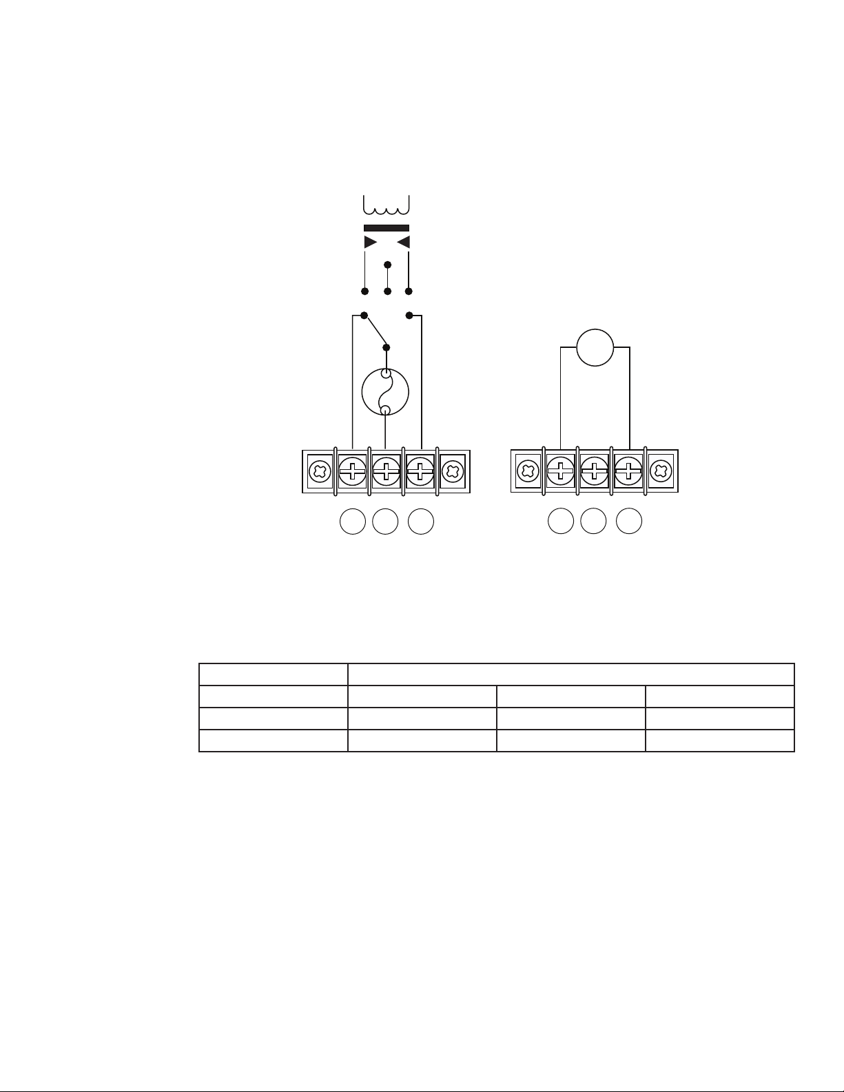
3.2.1 Screw Terminals
Figure 8 shows the wiring confdigurations of the rear terminals connections for Alarms
and optional Isolated Analog terminals.
0-24mA OUTPUT SOURCE
0-10V OUTPUT SOURCE
+ -
1
ALARMS 1 & 2
3
1
ISO ANALOG
3
Figure 8. Benchtop Meter Wiring Diagram.
Table 9. Conguration for Terminals.
Terminal Numbers
Conguration 3 2 1
Alarms 1 and 2* Normally Open Relay Common Normally Closed
ISO Analog Analog Output Not Connected Analog Return
* 3A 30V Max Dry Contact
10
Page 15
SECTION 4 CONFIGURATION AND PROGRAMMING
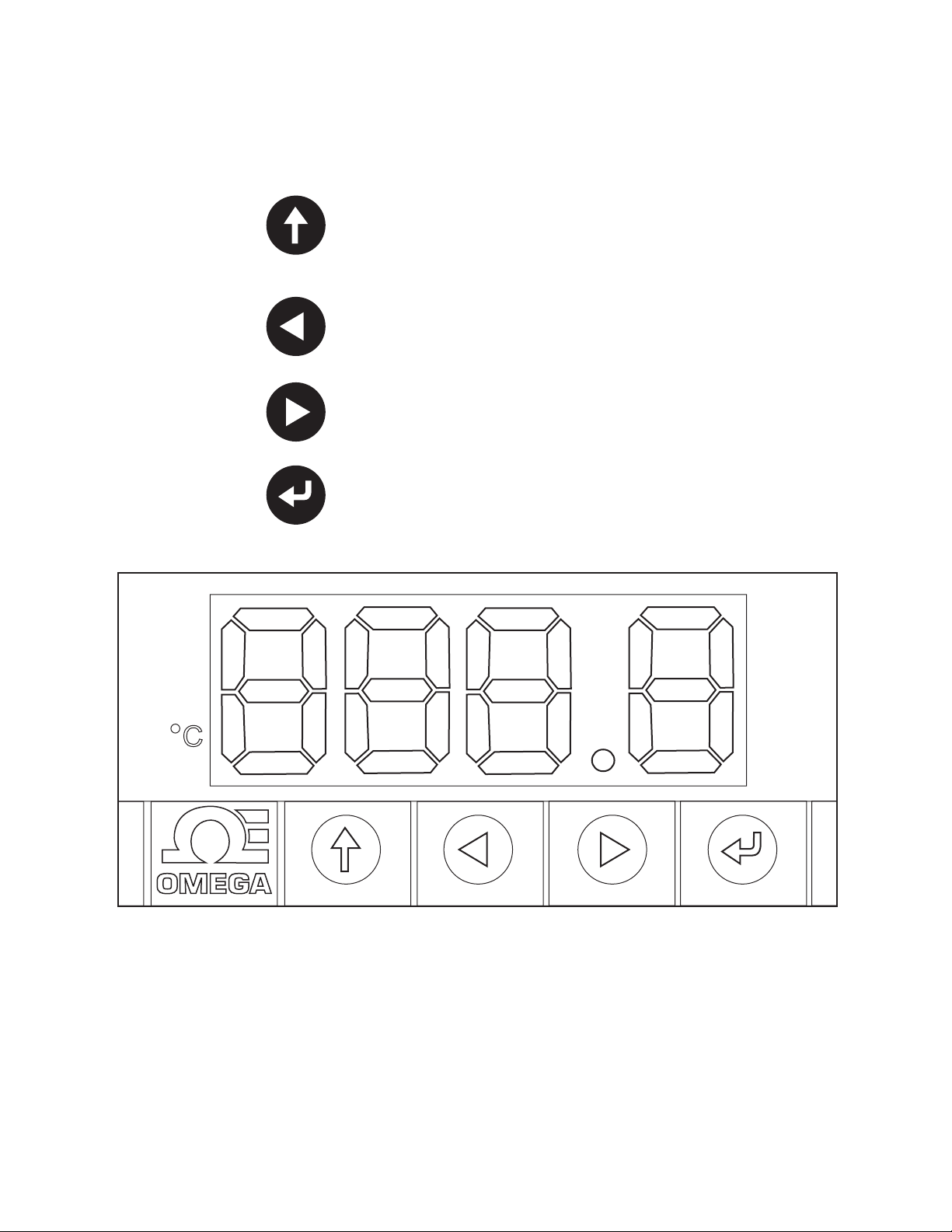
4.1 Controls
The UP Button moves up a level in the menu structure. Pressing and
holding the UP Button navigates to the top level of any menu (oPER,
PRoG, or INIt). This is a useful way of reorienting if you get lost in the
menu structure.
The LEFT Button moves across a set of menu choices at a given level.
When changing numerical settings, press the LEFT Button to make the
next digit (one digit to the left) active.
The RIGHT Button moves across a set of menu choices at a given
level. The RIGHT Button also increments numerical values. When
incrementing a digit past “9” it returns to “0”.
The ENTER Button selects a menu item and goes down a level. It also
enters a numerical value or parameter choice.
Figure 9. MDS8PT LED Display.
11
Page 16
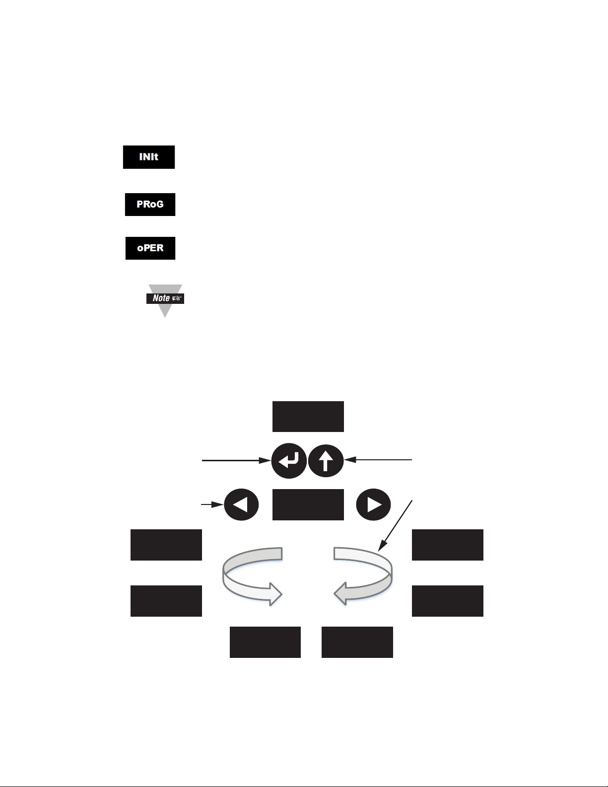
4.2 Menu Structure
The menu structure of the Platinum Series Display Meter is divided into three
mainLevel-1Modes:Initialization(INIt), Programming (PRoG) and Operations
(oPER).
Initialization Mode: These settings are rarely changed after initial set up. They
include transducer types, calibration, etc. These settings can be password
protected.
Programming Mode: These settings are frequently changed. They include set
points, Control Modes, Alarms, etc. These settings can be password protected.
Operating Modes: The setting of this mode allow users to switch between Run
Mode, Standby Mode, and Manual Mode etc.
ForadetaildiscussionofLevels2thru8,refertothePlatinumSeries
Temperature and Process Meters- User’s Manual (M5460).
Figure 10 illustrates how to use the LEFT and RIGHT Display Buttons to navigate around
a menu selection.
Press the ENTER Button on
oPER to select and enter
RUN Mode
Press the LEFT and RIGHT
Buttons to navigate around
the Operating Mode option
Stby
PEAk
oPER
RUN
LRSTVALy
Figure 10. Circular Flow of Menus.
Press the UP Button to
navigate back up a level
Cycle through any menu
in both directions
SP1
SP2
12
Page 17

4.3 Selecting an Input
The Benchtop Meter features a User Programmable Universal Input. Select the input
type using TABLE 10. Initialization Mode Menu, below. Refer to Section 3.1.2 to 3.1.3
for Input Wiring Diagrams.
Level 1Level 2Level 3Level 4Level 5Level 6Level
Notes
7
INIT INPt t.C. k Type K thermocouple
J Type J thermocouple
t Type T thermocouple
E Type E thermocouple
N Type N thermocouple
R Type R thermocouple
S Type S thermocouple
b Type B thermocouple
C Type C thermocouple
Rtd N.wIR 3 wI 3-wire RTD
4 wI 4-wire RTD
2 wI 2-wire RTD
A.CRV 385.1 385calibrationcurve,100Ω
385.5 385calibrationcurve,500Ω
385.t 385calibrationcurve,1000Ω
392 392calibrationcurve,100Ω
3916 391.6calibrationcurve,100Ω
tHRM 2.25k 2250Ωthermistor
5k 5000Ωthermistor
10k 10,000Ωthermistor
PRoC 4–20 Process input range: 4 to 20 mA
Note:
ThisManualandLiveScalingsubmenuisthesameforallPRoC ranges.
MANL Rd.1 ----- Lowdisplayreading
IN.1 ----- Manual input for Rd.1
Rd.2 ------ High display reading
IN.2 ----- Manual input for Rd.2
LIVE Rd.1 ----- Lowdisplayreading
IN.1 ----- LiveRd.1input,ENTERforcurrent
Rd.2 ----- High display reading
IN.2 ----- LiveRd.2input,ENTERforcurrent
0–24 Process input range: 0 to 24 mA
+-10 Process input range: -10 to +10 mA
+-1 Process input range: -1 to +1 mA
+-0.1 Process input range: -0.1 to +0.1 mA
Table 10. Selecting Inputs.
13
Page 18
4.4 Alarm Conguration (PRoG > ALM. #)
ThePLATINUMSeriesBenchtopMetersupportstwoAlarms.EachAlarmcanbe
connected to an internal Single Pole Double Throw (SPDT) Mechanical Relay.
The Alarms are programmed using the Program Submenu. Alarm 1 and 2 have identical
defaultsettingsandsubmenuforconguringtheAlarmfunctions.Abriefoutlineof
Alarm settings is below.
Alarm Settings include:
Setting Alarm Function
tyPE Alarm type
ALR.H Alarm High parameter, used for Alarm trigger calculations.
ALR.L Alarm Low parameter, used for Alarm trigger calculations.
A.CLR Alarm Color indication.
ForamoredetaileddiscussionofsettingupandconguringtheAlarm
functions, refer to the Platinum Series Temperature and Process Meters User’s Manual (M5460).
4.4.1 Setting Alarm Type
Use the Alarm Type (tyPE) parameter to control the basic behavior of the
selected alarm.
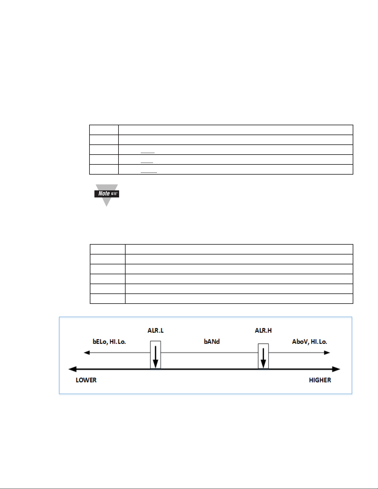
Types Alarm Behavior
oFF Alarm is off (factory default)
AboV AlarmistriggeredwhentheprocessvalueexceedsALR.H.
bELo AlarmistriggeredwhentheprocessvalueislessthanALR.L.
HI.Lo AlarmistriggeredwhentheprocessvalueisoutsidetheALR.L–ALR.H.
bANd AlarmistriggeredwhentheprocessvalueiswithintheALR.L–ALR.H.
Figure 11. Alarm Range Option Diagram.
14
Page 19

4.4.2 Setting Alarm High/Low References:
• AlarmHighReference(PRoG>ALM.#>ALR.H).
• AlarmLowReference(PRoG>ALM.#>ALR.L).
1. Use the button to select a digit to change;
2. Then select the button to increment the digit;
3. Save the setting with the button.
4.4.3 Setting the Alarm Color (PRoG > ALM.# > A.CLR)
The Benchtop Meter can change color in the display when an alarm is triggered.
The Alarm color options are listed below.
Setting Description
REd Alarm conditions are displayed in red. (Factory default)
AMbR Alarm conditions are displayed in amber.
GRN Alarms conditions are displayed in green.
dEFt Alarms do not display color.
4.4.4 Activating a Relay (PRog > dtR# > Mode)
To activate a relay when an alarm is triggered, change the output type of the
relaytothedesiredalarm.PRoG>DTR.#>Mode.
Setting Function
oFF Turn off the output channel. (Factory default)
ALM.1 Set the output to be an Alarm, activating when alarm conditions accord-
ingtotheALM.1congurationparametersareactive.
ALM.2 Set the output to be an Alarm, activating when alarm conditions accord-
ingtotheALM.2congurationparametersareactive.
15
Page 20
4.5 Analog Output
TheoptionalAnalogOutputcanbeconguredtotransmitaVoltageorcurrentsignal
proportionaltotheInput.SelecttheoutputtypeinthePRog.>IAN.1>RNGEmenu.
Foramoredetaileddiscussionofsettingupandconguringthe
Analog Output. Refer to the Platinum Series Temperature and
Process Controllers - User’s Manual (M5451).
4.5.1 Select an Output Type
The scaling of input readings to output voltage or current is fully user
congurable.
Type Description
0-10 0 to 10 Volts (factory default)
0-5 0 to 5 Volts
0-20 0 to 20 mA
4-20 4 to 20 mA
0-24 0 to 24 mA
4.5.2 Set Mode to Retransmission
Enable the output by setting the mode to Retransmission
(PRog.>IAN.1>Mode>RtRN)
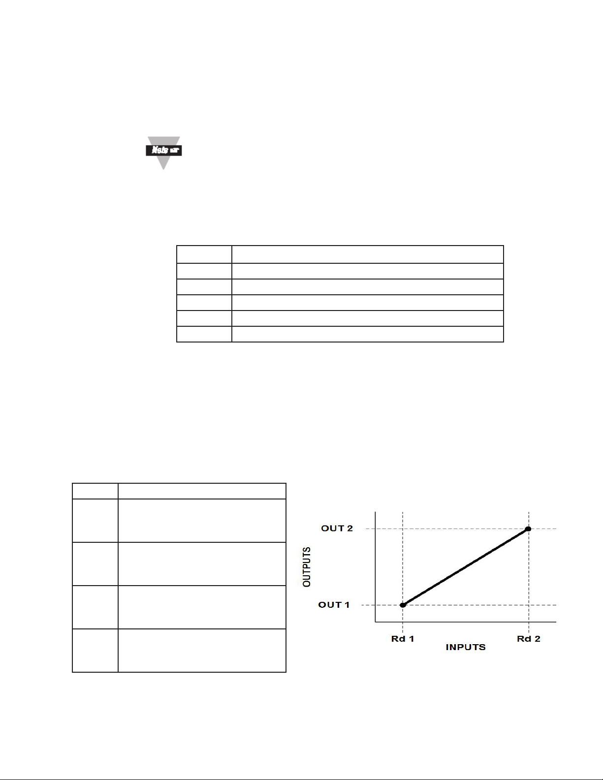
4.5.3 Set Scaling
The retransmission signal is scaled using the following 4 parameters. The unit
willdisplaytherstscalingparameter,Rd1, after RtRN is selected.
Setting Parameters
Rd1 Process reading 1; the process
reading that corresponds to the
output signal oUt1.
oUt1 The output signal that
corresponds to the process value
Rd1.
Rd2 Process reading 2; the process
reading that corresponds to the
output signal oUt2.
oUt2 The output signal that
corresponds to the process value
Rd2.
Figure 12. Alarm Scaling Diagram.
16
Page 21
SECTION 5 SPECIFICATION
ForadetaillistofSpecicationsforthePlatinumMeter,refertothe
Temperature and Process Meters - User’s Manual (M5460 - Section 7).
Table 11. Benchtop Meter Specications Summary.
Model MDS8PT
Sensor Input(s) Channel Single-Channel, Universal Input
Power All Models:
Fused:
Alarm Output 1 and 2:
Fused:
Isolated Analog,
Output Option:
Enclosure:
Material:
Size:
Weight: MDS Platinum Series 1.36 kg (3 lb)
90 to 240 VAC 50/60 Hz, 4W
Time-Lag,0.1A,250V
SPDT Relay, Class “C” 30 VRMS Max.
Time-Lag,3A,250V
1.5 kV Isolation, programmable for control or retransmission; Voltage Output
0-10 V output. 500 Ohms Min. Accuracy 0.1%; Current Output 0-20 mA output.
500 Ohms Max Accuracy is 0.1% ; Step response time 100 ms.
Case - Plastic (ABS), Handle -Anodized Aluminum
20.95 W x 9.525 H x 20.32 cm D
(8.25 W x 3.75 H x 8” D)
5.1 Approval Information
EMC:
2014/30/EU (EMC Directive)
Electrical Safety: 2014/35/EU (Low Voltage Directive)
Safety requirements for electrical equipment for
measurement, control, and laboratory.
Double Insulation; Pollution Degree 2
Dielectric withstand Test per 1 min
• Power to Input/Output: 2300 Vac (3250 Vdc)
• Ethernet to Inputs: 1500 Vac (2120 Vdc)
• Isolated RS232 to Inputs: 500 Vac (720 Vdc)
• Isolated Analog to Inputs: 500 Vac (720 Vdc)
ADDITIONAL INFORMATION:
FCC: This device complies with Part 15, Subpart B, Class B of the FCC rules, for option –EIP only.
RoHS II: The above product has been declared by the original supplier as Compliant. The manufacturer of this item
declares that the product complies with the EEE RoHS II Directive 2011/65/EC.
UL File Number: E209855
1 I/O signal and control lines require shielded cables, and these cables must be located on conductive cable trays or in conduits.
The length of these cables should not exceed 30 meters.
Measurement Category I
Category I includes measurements performed on
circuits not directly connected to the Mains Supply
(power).MaximumLine-to-Neutralworkingvoltageis
50Vac/dc. This unit should not be used in Measurement
Categories II, III, and IV.
Transients Overvoltage Surge (1.2 / 50uS pulse)
• Input Power: 2500 V
• Input Power: 1500 V
• Ethernet: 1500 V
• Input/Output Signals: 500 V
17
Page 22
SECTION 6 MAINTENANCE
These are the maintenance procedures required to keep the Benchtop Meter in optimal
performance.
6.1 Calibration
This unit is calibrated to give optimum performance over its full operating range.
Additional user calibration is available with adjustable gain and offset as well as ice
paint calibration. Refer to Temperature and Process Meters - User’s Manual (M5460) for
additionalinformationonusercalibrationtoadjustthemetertoaspecicapplication.
6.2 Cleaning
Lightlydampenasoftcleanclothwithamildcleaningsolutionandgentlycleanthe
Benchtop Meter.
Remove all electrical connections and power before attempting any cleaning.
Do not insert any foreign objects into the Benchtop Meter.
6.3 Fuse Replacement
The Benchtop Meter contains three (3) fuses to protect operation. Fuse F1 is used to
provide AC Power protection. Fuse F2 is used to protect the Alarm 1 Relay. Fuse F3 is
used to protect Alarm 2 relay. Refer to Table 11 below for Fuse ratings.
Disconnect all power from source before attempting fuse replacement.
Forcontinuedprotectionagainstriskofre,replacefuseswithonlythesame
size, type and rating with safety approvals indicated here and on the rear
panel of the Benchtop Meter.
Fuse* Type
Rear Panel Fuse (F1) 0.1A 250V, 5x20mm, Slow Blow
Rear Panel Fuse (F2, F3) 3.0A 250V, 5x20mm, Slow Blow
Table 12. Fuses
*ForallModels:UL./CSA/VDEApproved.
18
Page 23

2016
Page 24

MQS5576/0916
 Loading...