

Page 1
User’s Guide
Data Loggers
Shop online at
omega.com
e-mail: [email protected]
For latest product manuals:
omegamanual.info
for OM-62, OM-63, OM-DVTH, OM-DVT4 and OM-DVCV
Logger Interface Software
Page 2

OMEGAnet®Online Service Internet e-mail
omega.com [email protected]
Servicing North America:
U.S.A.: Omega Engineering, Inc., One Omega Drive, P.O. Box 4047
ISO 9001 Certified Stamford, CT 06907-0047 USA
Canada: 976 Bergar
Laval (Quebec), Canada H7L 5A1
Toll-Free: 1-800-826-6342 TEL: (514) 856-6928
FAX: (514) 856-6886 e-mail: [email protected]
For immediate technical or application assistance:
U.S.A. and Canada: Sales Service: 1-800-826-6342/1-800-TC-OMEGA
Customer Service: 1-800-622-2378/1-800-622-BEST
Engineering Service: 1-800-872-9436/1-800-USA-WHEN
Mexico: En Español: 001 (203) 359-7803 FAX: (001) 203-359-7807
®
®
®
Servicing Europe:
Benelux: Managed by the United Kingdom Office
Czech Republic: Frystatska 184
733 01 Karviná, Czech Republic
Toll-Free: 0800-1-66342 TEL: +420-59-6311899
FAX: +420-59-6311114 e-mail: [email protected]
France: Managed by the United Kingdom Office
Toll-Free: 0800 466 342 TEL: +33 (0) 161 37 29 00
FAX: +33 (0) 130 57 54 27 e-mail: [email protected]
Germany/Austria: Daimlerstrasse 26
D-75392 Deckenpfronn, Germany
Toll-Free: 0 800 6397678 TEL: +49 (0) 7059 9398-0
FAX: +49 (0) 7056 9398-29 e-mail: [email protected]
United Kingdom: OMEGA Engineering Ltd.
ISO 9001 Certified One Omega Drive, River Bend Technology Centre, Northbank
Irlam, Manchester M44 5BD England
Toll-Free: 0800-488-488 TEL: +44 (0)161 777-6611
FAX: +44 (0)161 777-6622 e-mail: [email protected]
It is the policy of OMEGA Engineering, Inc. to comply with all worldwide safety and EMC/EMI
regulations that apply. OMEGA is constantly pursuing certification of its products to the European New
A
pproach Directives. OMEGA will add the CE mark to every appropriate device upon certification.
The information contained in this document is believed to be correct, but OMEGA accepts no liability for any
errors it contains, and reserves the right to alter specifications without notice.
WARNING: These products are not designed for use in, and should not be used for, human applications.
Page 3

Table of Contents
Quick Start ................................................................................................................... 5
Overview ...................................................................................................................... 5
Connecting the Logger to Your PC .............................................................................. 5
Setting Up the Logger To Record Data ........................................................................ 6
Custom Interval Setup ................................................................................................. 7
Alarm Setup ................................................................................................................. 7
Using the Software to Check Logger Status ................................................................. 8
General Logger Status and Data In Memory Pane .................................................................. 8
Alarm Status Pane .................................................................................................................... 9
Last Sample Pane ................................................................................................................... 10
Ending the Logging Session ...................................................................................... 10
Powering Down the Logger ........................................................................................ 10
Loading Logger Data ................................................................................................. 10
Automatic Data Retrieval ........................................................................................... 11
Working With the Data Graph .................................................................................... 12
Using the Zoom Feature ............................................................................................ 13
Data Listing Window .................................................................................................. 14
Data Summary and Statistics ..................................................................................... 14
Hiding or Viewing Channels ....................................................................................... 15
Exporting Logger Data ............................................................................................... 15
Printing the Logger Data ............................................................................................ 16
Calibrating the Logger ................................................................................................ 16
Setting the Calibration Password ............................................................................... 17
Setting the Logger Real Time Clock ........................................................................... 17
Data Security ............................................................................................................. 18
Specifications ............................................................................................................ 19
OM-62 Temperature Humidity Logger ........................................................................ 19
OM-62 Logger Status LED ......................................................................................... 19
Replacing the OM-62 Battery ..................................................................................... 20
OM-62 Specifications ................................................................................................. 21
OM-63 Temperature Logger ...................................................................................... 21
OM-63 Logger Status LED ......................................................................................... 21
Replacing the OM-63 Battery ..................................................................................... 22
OM-63 Specifications ................................................................................................. 23
OM-DVTH Temperature Humidity Logger with Display .............................................. 23
Turning the OM-DVTH On and Off ............................................................................. 23
OM-DVTH Sample Screen ......................................................................................... 24
The OM-DVT H Summ ary Screen............................................................................... 25
OM-DVTH Graph Screen ........................................................................................... 25
Page 4

OM-DVTH Buttons ..................................................................................................... 26
Replacing the OM-DVTH Battery ............................................................................... 26
OM-DVTH Specifications ........................................................................................... 27
OM-DVT4 Four Temperature Logger with Display ..................................................... 27
Turning the OM-DVT4 On and Off ............................................................................. 28
OM-DVT4 Sample Screen ......................................................................................... 28
OM-DVT4 Difference Screen ..................................................................................... 29
OM-DVT4 Summary Screen ...................................................................................... 29
OM-DVT4 Graph Screen ........................................................................................... 30
OM-DVT4 Buttons ..................................................................................................... 30
Replacing the OM-DVT4 Battery ................................................................................ 31
OM-DVT4 Specifications ............................................................................................ 31
OM-DVCV Current Voltage Logger with Display ........................................................ 31
Connecting the OM-DVCV to Electrical Equipment .................................................... 32
OM-DVCV Real Time Monitoring ............................................................................... 32
Turning the OM-DVCV On and Off ............................................................................. 33
Ending the Logging Session on the OM-DVCV .......................................................... 33
OM-DVCV Sample Screen......................................................................................... 33
OM-DVCV Summary Screen ..................................................................................... 34
OM-DVCV Graph Screen ........................................................................................... 35
OM-DVCV Buttons ..................................................................................................... 35
Replacing the OM-DVCV Battery ............................................................................... 36
OM-DVCV Specifications ........................................................................................... 36
Page 5

OmegaLog User’s Guide Version 1.5x 5/36
Quick Start
Follow the procedure below to start using your data logger:
1. Connect the data logger to a free USB port on your computer.
2. Start the OmegaLog Interface Program.
3. From the Logger menu, select Setup.
4. Select the "Logging starts immediately when setup is complete" option.
5. Click Continue to start lo gging.
The logger i s now logging data. You ca n click on the
has been lo gged.
icon on the toolbar to download and view the data that
Overview
The Omega USB data loggers are versatile devices that can be used for a wide range of logging applications. Each
logger is capable of sampling data as fast as once per second or as slow as once every 18 hours. Each logger can
stop recor di ng when me mo r y becomes full, or rollover for continuous recording. The start of recording is software
selectable to be immediate, delayed, or initiated when the Start button is press.
The loggers can also be used to monitor high and low ala rm events, that indicate if the recorded data passed above
and/or below the user selected threshold. The loggers have a visual indication of an alarm condition.
Each USB logger has an internal real time clock/calendar. This real time clock is used to record the time stamps for
data samples. This real time clock is independent of your computer clock, and can be set separately, or set to match
your computer clock.
The USB loggers are extremely low power. Under normal operating conditions, t he battery will last several years.
Connecting the Logger to Your P C
Your logger comes complete with the software and the USB interface cable. To connect the logger to your
computer, follow these steps:
1. Connect the USB cable to the logger and to a free USB port on your computer.
2. If you are connecting the logger to the PC for the first time, the logger will automatically be recognized and
installed on your computer.
3. Start the OmegaLog pro gram and click on the
The logger status scree n should no w be displayed.
Note: The Windows operating system can not handle USB devices being unplugged and replugged too
fast. When unplugging the logger, wait for about 5 seconds before plugging it (or any other USB device)
in again. If you unplug and replug a device too quickly, the computer may stop recognizing any USB
devices on that port. If this happens, the only solution is to restart the computer. This is a Windows USB
problem and is not related to the OmegaLog software.
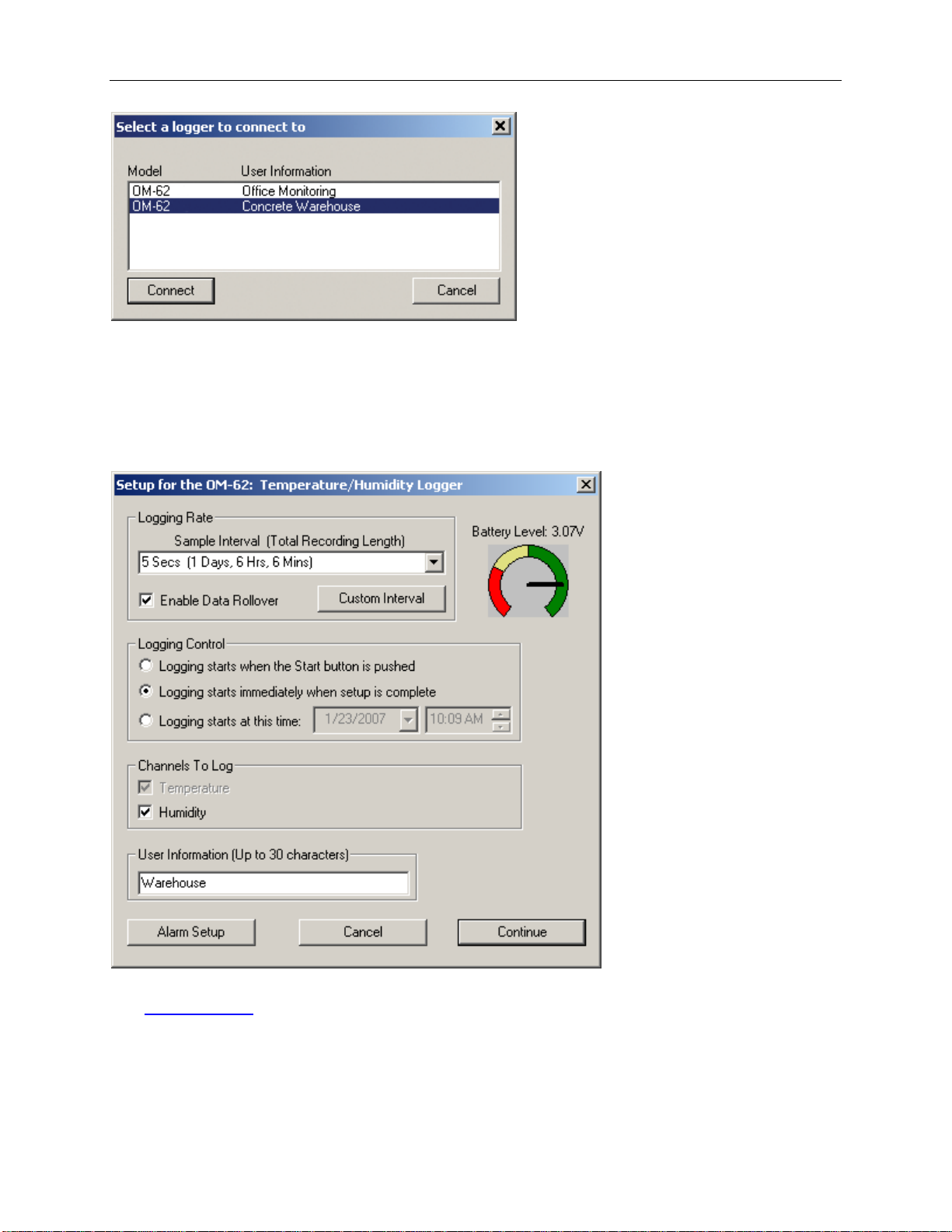
If more then one logger is connected to your computer at the same time, the program will ask you to select one of
the loggers:
icon on the toolbar.
Page 6
OmegaLog User’s Guide Version 1.5x 6/36
To select a logger click on one of the loggers on the list, and click the Connect button.
Setting Up the Logger To Recor d Data
To set your logger to start recording data, select Setup from the Logger menu. The setup options window is shown
below.
• Sample Interval (Total Recording Length): Select the sample interval from a predefined list of intervals.
• Custom Interval: Add your own interval to the sa mp le interval list.
• Enable Data Rollover: Check this box to have the logger continuously record the data, overwriting earliest
recorded data. When this bo x is not checked, logging is stopped when the logger memory beco mes full.
• Logging Control: Logging can start in three ways depending on the selection you make :
o Logging starts when the Start button is pushed: Logging will start when the Start button is pushed for
Page 7
OmegaLog User’s Guide Version 1.5x 7/36
about 3 seconds.
o Logging starts immediately when setup is complete: Log ging will start immediately once the Continue
button is clicked.
o Logging starts at this time: Logging will start at the user specified time. There is no limit how far in the
future you can set the logging to start.
• Channels to Log: You can elect to disable unused logger channels. When a channel is disabled , its memory is
allocated to the other channels, increasing the total logging time. The total logging time will be reflected in the
Sample Interval window. Depending on the logger, some channels are required and cannot be disabled.
Channels that can not be disabled are grayed out and can not be unchecked. For instance, in the picture above,
the Temperature channel is required to record Relative Humidity, so the Temperature channel cannot be
disabled. At least one channel must be enabled for logging.
• User Information: Enter any text you like in this box. This field is used to identify the logger to the user.
You can enter descriptive location, serial number, etc.
• Alarm Setup: Click this button to open the
Alarm Setup Window.
Custom Interval Setup
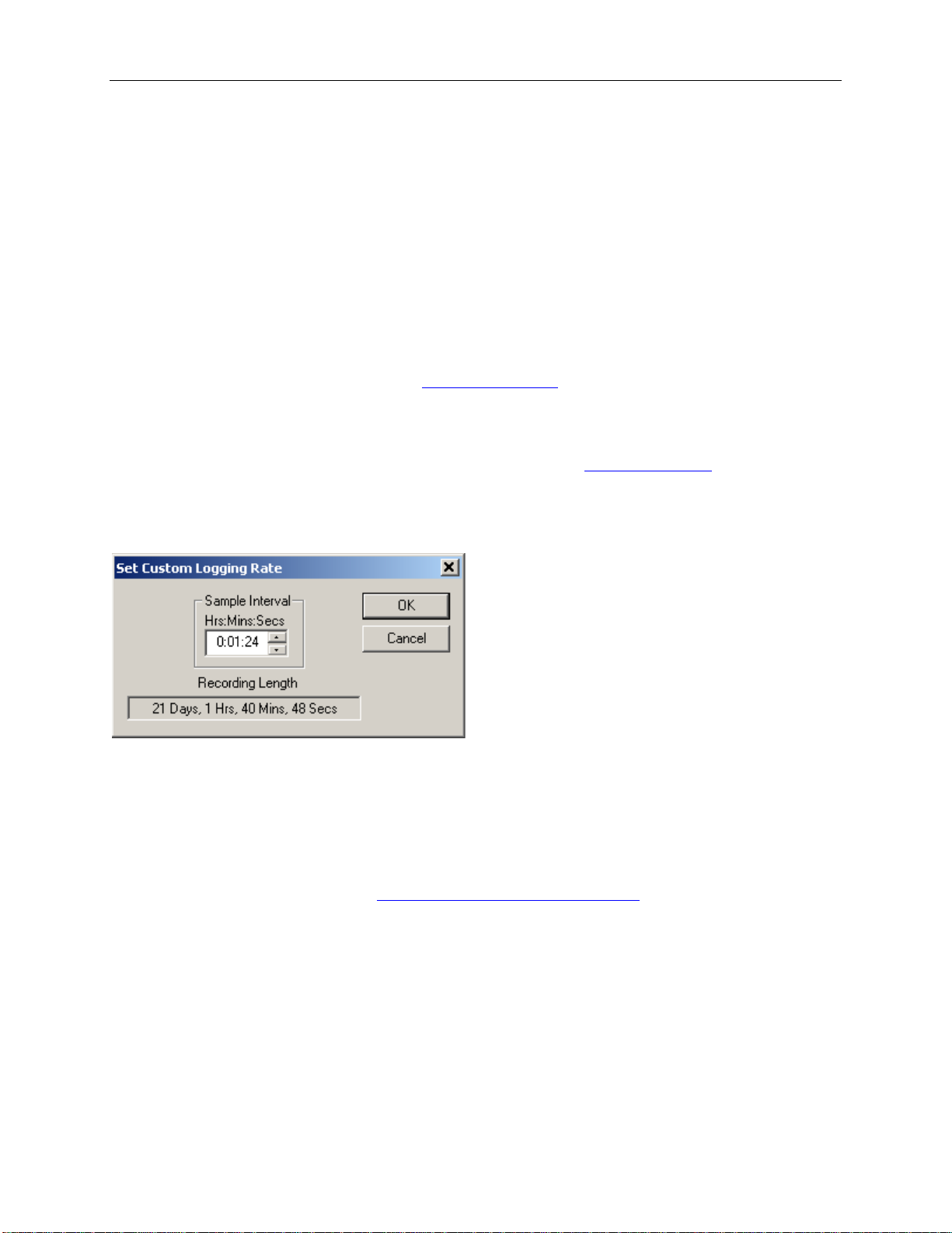
Commonly used intervals are predefined in the Sample Interval box in the Logger Setup screen. If needed, a
custom interval can be defined by the user. This is done b y clicking on the Custom Interval but ton in the Log ger
Setup screen. The custom interval window will popup , a s shown below. You can s elect a custom logging int erval
using this wi nd o w.
In the window above, the sampling interval was set to 1 minute, 24 seconds, to allow a 3 week recording.
Alarm Setup
Alarms are used to indicate whether or not the data inside the logger exceeded a user specified threshold. This c an
be an indication that an important event has occurred and the data is worth downloading and looking at . The alarm
status is indicated visually by pr e ssing the
when no alarms occurred. The LED will flash red when an alarm has occurred and is stored in logger memory.
Check button and watching the LED light. The LED will flash gr e en
Page 8
OmegaLog User’s Guide Version 1.5x 8/36
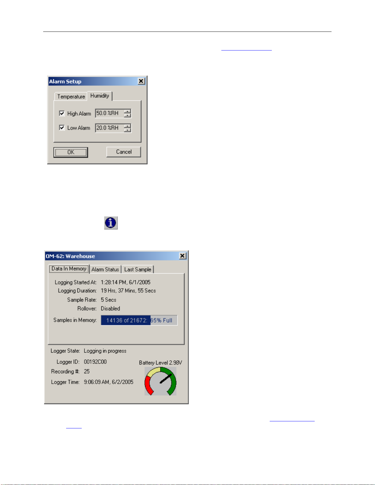
To get to the Alarm Setup window, click the Alarm Setup b ut ton in the
windows allows you to set high and/or low alarm thresholds for each logger channel, or disable these alarms.
Alarms are set by entering the thresholds as shown in the windo w be l ow.
The checkbox to the left of the low/high alarms enables the alarm when checked, and disables the alarm when clear.
Logger Setup screen. The Alarm Setup
Using the Software to Check Logger Status
Selecting Status from the Logger menu brings up the Logger Status window. You can also bring up the status
window by p ressing the
button on the toolbar. The logger status screen is separated into three panes:
General Logger Status and Data In Memory Pane
Logger State shows the internal st ate of the logger:
o Power Save Mode: This mode is entered when the battery is replaced, or the user
logger. The logger battery is not used in this mode and can last for up to 10 years. The logger's real time
clock is not running in this mode.
powered down the
Page 9
OmegaLog User’s Guide Version 1.5x 9/36
o Idle, waiting for setup: The logger is not logging. It is waiting for a setup from the user. T he logger's
real time clock is active in this mode.
o Logging will start on button press: Loggi ng has been setup to start when the logger's Start button is
pressed.
o Logging will start at xxxx: Delayed logging. Logging has been selected to start at a future time. The
logger is waiting for this time to arrive to start logging.
o Logging in Progress: The logger is currently logging data.
• Logger ID: An ID that is unique for each logger. This ID can be used to ensure t hat the logged data has not
been tampered with. See the
• Recording #: Indicates the number of times the logger has been setup to log. This counter can be used to
ensure that the logged data has not been tampered with. See the
• Logger Time: Shows the date and time of the logger's real time clock.
• Battery Level: Shows the current level of the logger's battery. It is recommended that the battery is replaced
when this indicator reaches yellow. When this indicator reaches red, it is imperative that the battery is replaced
before logging becomes unpredictable.
• Logging Started At: Shows at what time the logging has started.
• Logging Duration: Shows how long the logging ses sion has bee n active.
• Sample Rate shows how often t he logger is re cording the data.
• Data Rollover shows how many times the sample memory wrapped around after becoming full.
• Samples in Memory: Shows information on how many samples are currently stored in the logger memory,
and how much space remains free. Note that if rollover occurs, this value will always be 100%.
Data Security section for more details.
Data Security section for more details.
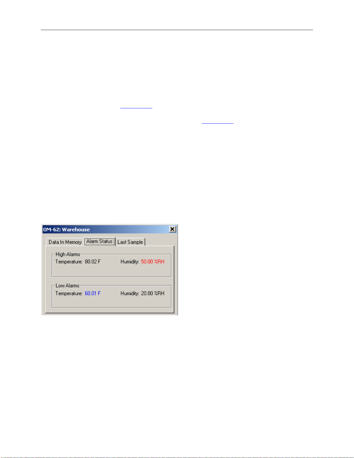
Alarm Status Pane
The Alarm Status pane displays the alarm thresholds for the active channels. If a high alarm oc curred the threshold
is displayed in red. If a low alarm occurred, the threshold is displayed in blue.
Page 10
OmegaLog User’s Guide Version 1.5x 10/36
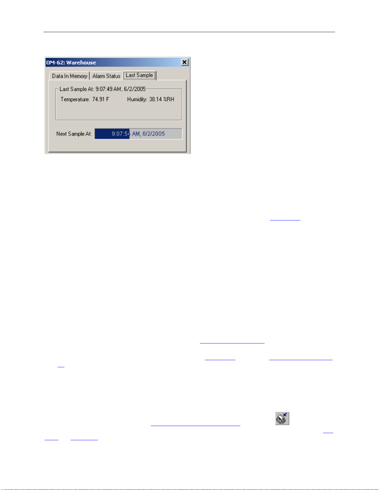
Last Sample Pane
The Last Sample pane shows the value of the last sample taken, for all the active channels. It also shows when the
next sample will be taken.
Ending the Logging Sessi on
There are a number of ways that the logging session can end:
1. When the logger memory becomes full, and data rollover was not selected during
will automatically stop loggin g and e nter the idle state.
2. Selecting End Logging f rom the Logger menu.
3. Logging will stop automatically if the logger detects a low battery condition.
4. If the battery is removed from the logger, logging will stop. No data will be lost.
Once loggi ng has ended, it cannot be resumed without erasing the logged samp les stored in the logger memory.
logger setup, the logge r
Powering Down the Logger
Your logger uses very little power and has a long battery life. If you want to extend the battery life farther, you can
power down the logger when it is not logging. In the power down mode the logger uses practically no power, and
can be stored without loosing battery power, as long as the battery shelf life allows (10 years for Lithium batteries, 6
years for Alkaline). This state is useful if the logger is going to be stored without being used for an extended period
of time.
• To put the logger into the power down mode, select Power Down from the Logger menu.
• To check if the logger is in power down mode, chec k the
indicated as Power Save Mode.
• The logger automatically exits power save mode when it is
set.
Note: The power down mode can only be entered when the logger is idle (not logging). In the power
down mode the logger's real time clock is not running.
logger status using the PC. Logger State will be
set up to log, or whe n the logger's real time clock is
Loading Logger Data
To get the sampled data from your logger, connect the logger to your computer and click the button on the
toolbar, or select Get Data from the Logger menu. Once the data is transferred from the logger to your PC, the
graph and data listing windows will be displayed.
data
Page 11

OmegaLog User’s Guide Version 1.5x 11/36
Logged data can be retrieved from the logger at any time. You do not have to stop the logging session to retrieve
the data.
graph display will be blank if there are less than two data points logged. The listing window will be blank if
The
there are no data points logged (as can happen during delayed logging, or when logging is set to start on button
press).
Automatic Data Retrieval
The OmegaLog Interface Software can be setup to automatically load the data from the logger into the computer as
samples become available. In this mode the
data.
To enable this feature follow these steps:
• Make sure that your logger is
• Make sure that the logger is logging data. Automatic retrieval is not available when the logger is not logging.
connected to your computer.
graph and the listing windows are updated automatically with the new
• Manually download the data for the first time by clicking the
from the Logger menu.
• From the Logger menu select Auto Update.
The computer will download data as often as the
collect data once every minute, the software will perform a download once a minute. Of course the logger has to be
connected to your computer while the Auto Update mode is active.
When the Auto Update mode is active, the software does not change the zoom level of your graph. Instead it scrolls
the graph as new data becomes available.
sampling interval you setup. For ins t ance, if you set your logger t o
button on the toolbar, or select Get Data
Page 12
OmegaLog User’s Guide Version 1.5x 12/36
Working With the Data Graph
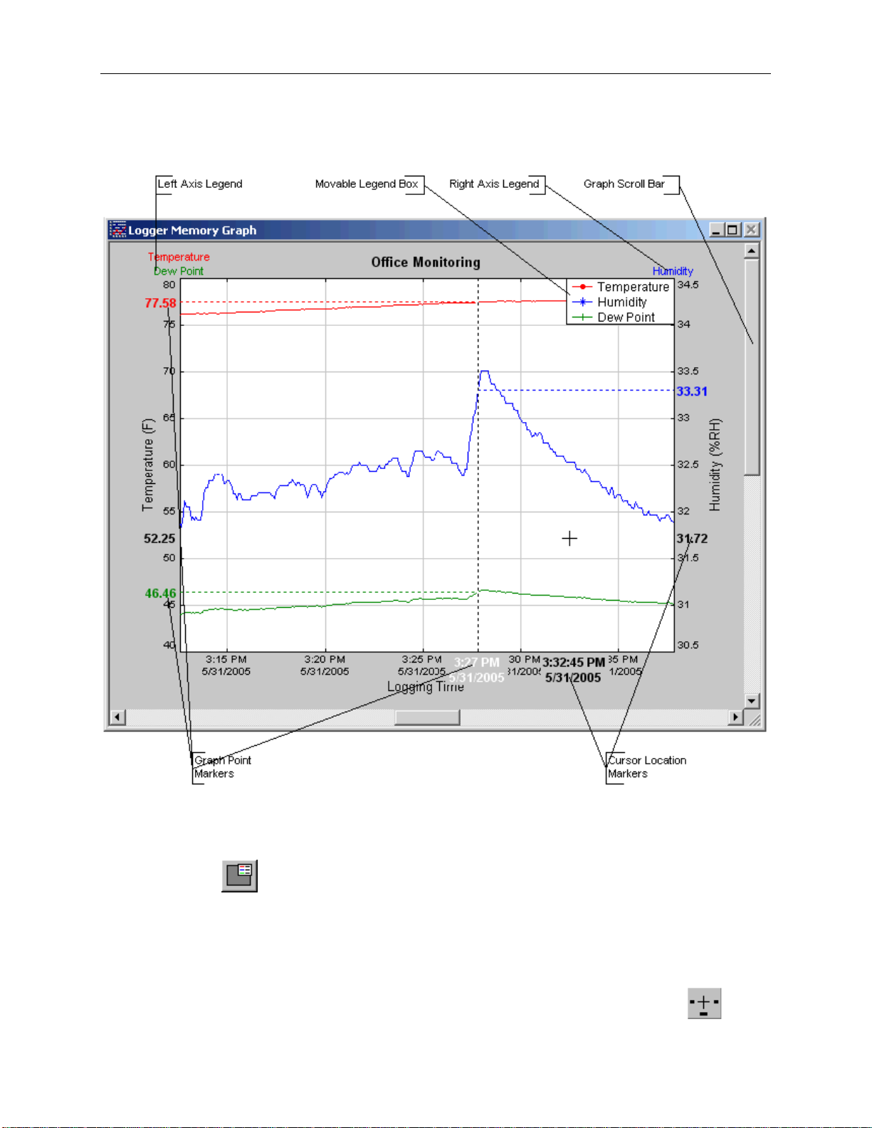
Clicking a nywhere within the graph window activat es the graph toolbar but tons and the graph window features.
• The graph plots each data channel using a different color and dot style. A small rectangular legend shows the
color and the dot style of each channel. This legend can be moved by clicking the left mouse button while
inside the legend and dragging the legend to where you want it to be. The legend can be turned ON and OFF
by pressing the
• There is an additional legend above each of the Y axis. This legend is the channel name drawn in t he same
color as the channel line on the graph. This legend helps identif y which channel belongs to which axis. For
instance, in the graph above, the Temperature in red and Dew Point in gre en corresp ond to the left Y axis, the
Relative Humidity in blue corresponds to the right Y axis.
• The Cursor Location Markers sho w the cursor position on the graph. The position is shown on each of t he axis
in a slightly larger, bold text. The position indicators can be turned ON and OFF by pressing the
button on the toolbar.
button
Page 13
OmegaLog User’s Guide Version 1.5x 13/36
on the toolbar
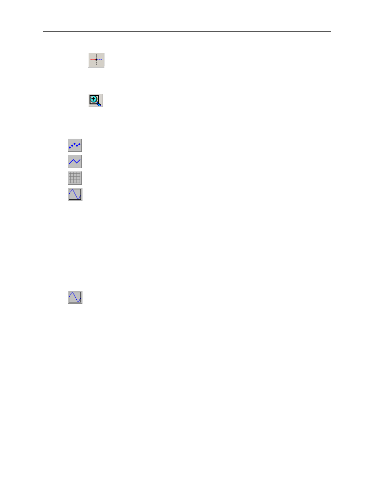
• Clicking the
on the grap h, marks this point, and shows the point values for al l channels, at the specified time. An example
of sample markers is shown above.
• During zoom mode, you can use the vertical and horizontal scroll bars to move the graph around.
• Clicking the
corner and drag the mouse, while holding down the b utton, to the opposite corner. Releasing the button will
activate the zoom. Clicking the right mouse button unzooms the graph one level. When the graph is z oomed,
you can use t he vertical and horizontal scroll bars to move the graph around. See
section for more details.
• The
• The
• The
• The
that the minimum and maximum scale wil l be about equivalent to t he minimum and the maximum of the data.
button turns ON and OFF the marks at the d a ta points.
button con nects the sample points with a line.
button turns the grid lines ON and OFF .
button on the toolbar causes the graph to unzoom to the full scale of the recorded data. This means
button activates the sa mple marker f unction. When this function is active, clicking a po i nt
button activates the zoom mode. To zoom to an area, click the left mouse button at one
Using the Zoom Feature
Using the Zoom Feature
There are a number of ways to zoom to the data you would like to see on the screen.
• Graphic Zoom: Yo u can graphic ally zoom on the portion of the data that is displayed on the screen by
pressing the left mouse button and dragging the box around the part of the graph you would like to zoom to.
You can repeat this until the grap h is zo omed to just a few points. Pressing the right mouse button reverses the
graphic zoom (causes unzoom).
• Unzoom: Pressing the left mouse button, then releasing it without dragging the mouse ca us es the graph to
unzoom (zoom out). Once ag ain pressing t he right mouse button reverses this zoom.
• The
minimum and maximum scale will be about equivalent to the minimum and the maximum of the data.
• Autoscaling a specific axis: You can also autoscale the time or one of the data axes only, without affecting
the other axes. To autoscale the time axis only, choose Time -> Auto Scale from the Zoom menu. To
autoscale one of the data axis only, choose Auto Scale for the appropriate channel from the Zoom menu.
• Numerical Zoom: Another w ay to specify the zoom is to enter the minimum and maximum limits of the
graph numerically. You can do this individually for the time axis and for each of the data axis. To do this,
select Custom for the appropriate axis from the Zoom menu, and enter the minimum and maximum limits for
the axis.
button on the toolbar causes the graph to unzoom to the full scale of the data. This means that the
Page 14
OmegaLog User’s Guide Version 1.5x 14/36
Data Listing Window
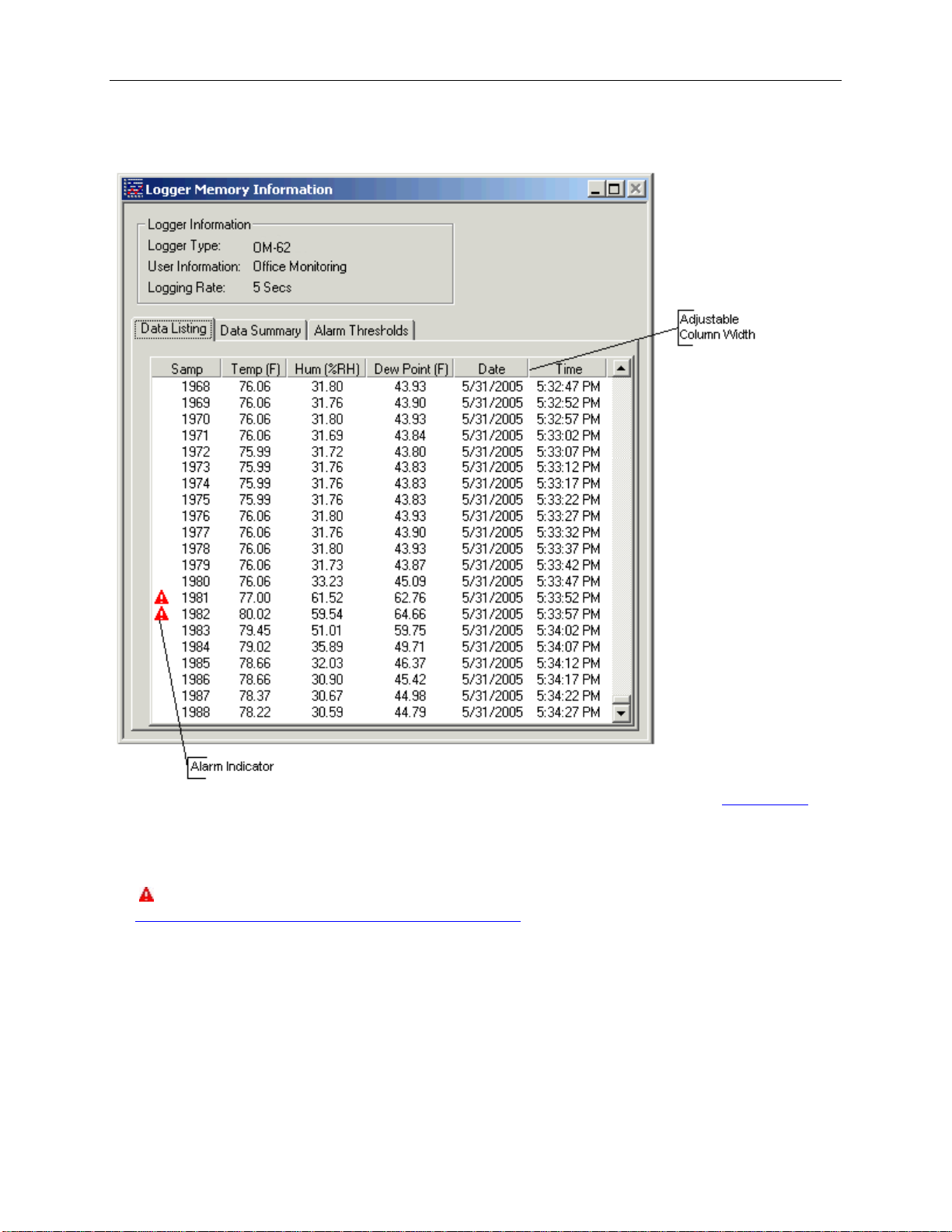
The data listing window is shown be low.
The Data pane lists the data samples collected by the logger. If the data rollover check box in the
cleared, the earliest data samples are listed. If the data rollover check box was checked, the latest data samples are
listed.
The column width of each column is adjustable by using the left mouse button and dragging t he column to the
desired width.
icon next to a data sample indicates an alarm condition. That is, one or more of the data channels are outside
The
minimum or maximum (alarm low and alarm high) thresholds.
the
setup windo w was
Data Summary and Statistics
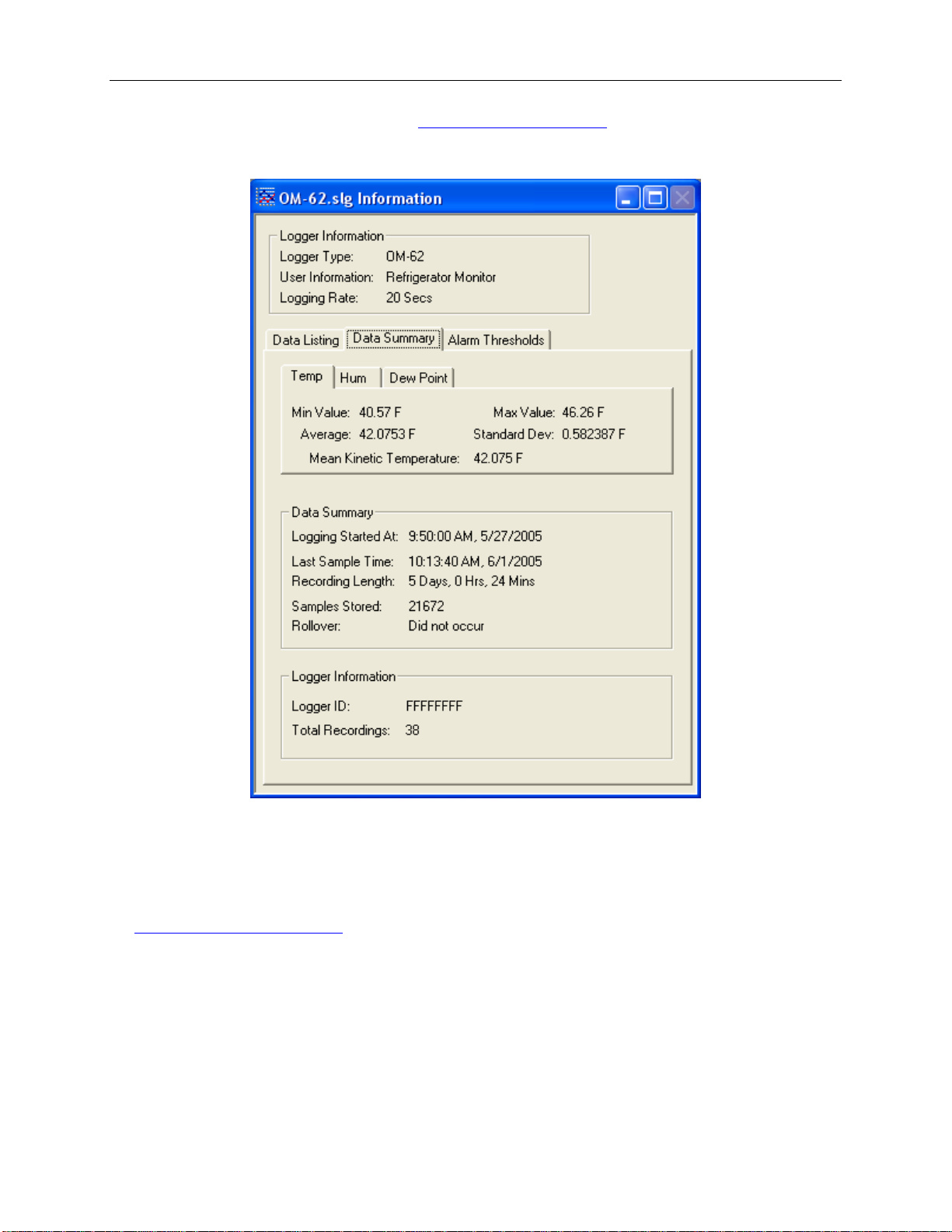
The Data Summary pane displays the summary and statistics for the currently loaded dataset. The statistics
displayed are: Minimum value, ma ximum value, average val ue (mean) and st andard deviation.
For temperature channels Mean Kinetic Temperature (MKT) is displayed as well. MKT is used in pharmaceutical
and food industries as a simplified way of expressing the overall effects of temperature fluctuation during storage
and transit of perishable goods. The software uses the activation energy value ΔH = 83.144 KJ/mol for MKT
calculation.
Page 15
OmegaLog User’s Guide Version 1.5x 15/36
The data statistics are also included when data is
A typical Data Summary window is shown below.
exported to a text or Excel file.
Hiding or Viewing Channels
The OmegaLog software has the ability to hide cha nnels you do not wish to vie w. This feature is accessed by
selecting Channels > from the View menu, and then deselecting or selecting the specific channels you wish to hide
or view. The hidden channels do no t a ppear in either the plot or the data listing. They also are not exported through
export to text and export to Excel features.
the
Exporting Logger Data
The OmegaLog software allows exp orting sample data and data statistics to a te xt file or to a Microsoft Excel file.
• To export sample data to a text file, select Export -> Text File from the File menu.
• To export sample data to a Microsoft Excel file, select Export -> Excel File from the File menu.
The file exported to Microsoft Excel is an Excel .csv file. The easiest way to open this file in Excel is to just double
click on the created file. The file can also be opened from within Microsoft Excel:
Page 16
OmegaLog User’s Guide Version 1.5x 16/36
1. From the Microsoft Excel application choose Open… from the File menu.
2. In the Open window, under Files of type:, select Text Files (*.prn, *.txt, *.csv).
3. Navigate to the directory where you saved the exported file. The file name should be listed in the window.
4. Select the file and click Open.
When you first open the .csv file in Excel, the Date Time column will be in a strange format. To convert to a normal
time and date format follow these steps:
1. Select the entire Date Time column by clicking on the column header (E).
2. While the cursor is in the column, click the right mous e button and select Format Cells.
3. Under Category: select Date or Time, then choose the format that suits you in the Type: column.
4. Click OK when done.
Printing the Logger Dat a
The OmegaLog software can print the data graph and data samples list. To print these, select Print from th e File
menu. You can also view how your dat a will be print ed using the Print Preview option from the File menu.
Graphs and data samples are printed as they appear on the screen. For graphs, this includes the current zoom detail,
marking of sample points, etc (see
For sample listing printout, any da ta filters applied to the data will be applied to the printed output as well. Data
filters are especially useful for reducing the amount of pages that the data sample printout generates.
Working with the Data Graph for more detail).
Calibrating the Logger
Your logger is factory calibrated to an accuracy given in the logger specifications. However, there may be times
when you wish to adjust the calibrat ion of your logger. NIST traceable calibration certificate is available at the
factory for an additional cost.
The OmegaLog software also provides you with the ability to perform a single point offset calibration. This
calibration can be used to increase the accuracy of your logger for a restricted data range. For instance, if your
application calls for logging temperature between 20°F and 32°F, you may want to calibrate your logger at 26°F.
Warning: Calibrating the logger erases the data that is stored in logger memory.
Calibration only can be performed when the logger is idle (not logging). To calibrate your logger, select
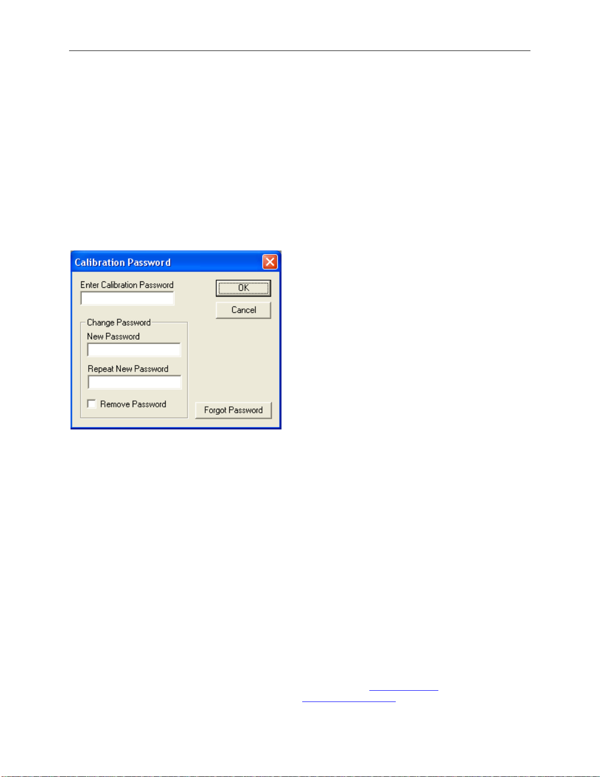
Calibrate… from the Logger menu. For extra security, calibration is password protected. You must enter the
correct password in the Calibration Password window before you’re allo wed to calibrate the unit, if a calibration
password has been created. The Password Calibration window also allows you to
Once the password is entered correctly, a window asking you to select the channel to calibrate pops up. Select the
channel you would like to calibrate and click OK. Each channel must be calibrated separately.
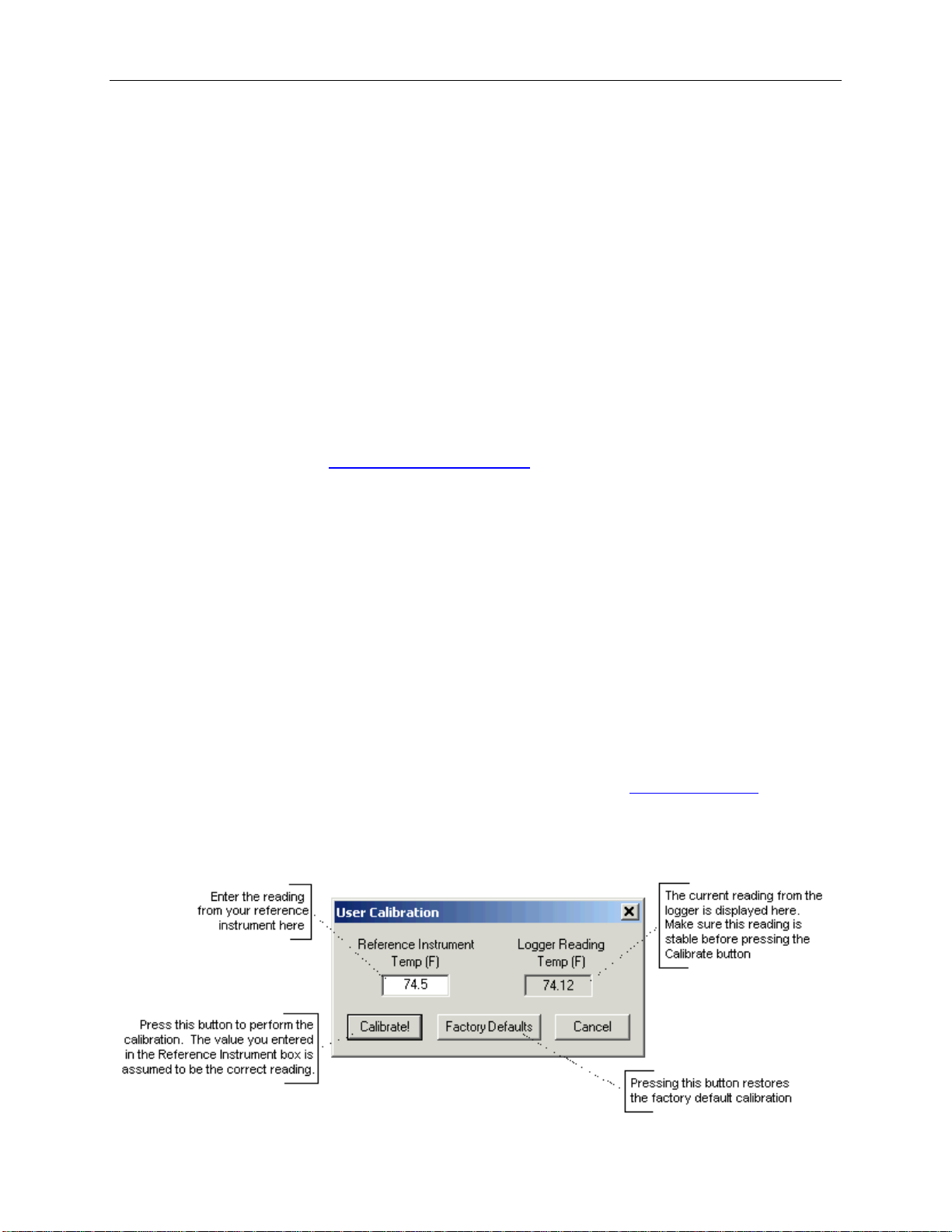
The User Calib ration window for the channel you selected will appear:
change the password.
Page 17
OmegaLog User’s Guide Version 1.5x 17/36
To perform the calibration:
1. Select a stable and accurate reference instrument. It is best to use a reference instrument that has at least 2
to 4 times the accuracy of the logger you are calibrating. For instance, if the accuracy of the logger
temperature channel is given as +/-1ºF, the accuracy of your reference instrument should be at least +/-
0.5ºF to +/-0.25ºF.
2. Make sure that both the logger and your reference instrument are reading the same stable source. For
temperature and humidity, it is best to place the logger and the reference sensor in a stable chamber.
3. Adjust your s ource to the value at which you would like to perform the calibra tion.
4. Wait for your reference instrument and the reading in the “Logger Reading” box to stabilize.
5. Enter the reading from your reference instrument in the “Reference Instrument” box, and hit the Calibrate!
button.
Setting the Calibrati on P a ssword
To change the calibration password select Calibrate… from the Logger menu. When the Calibration Password
window is displayed, follow these ste ps:
• Enter the current calibration password in the “Enter Cal i bration Password” box. If you are setting the
password for the first time, do not ent er anything in this box, since the logger is factory configured not to have
a password as a default.
• Enter the new password in the “New Pa s sword” box.
• Enter the new password again in the “Repeat New Password” box.
• Click OK.
You can also remove password protection (restore factory default empty password) by checking “Remove
Password”.
If you forgot the calibration password and need to reset it, click the Forgot Password button. This will reset the
logger password to factory default (empty password). Resetting the password in this way will erase the data stored
in the logger and reset the recording counter to 0.
Setting the Logger Real Time Cloc k
Each logger has an internal Real Time Clock. This clock is updated every second. During logging, the time stamps
of the data samples are set by the Real Time Clock.
When you first connect a new battery to the logger, or when the lo gger is in
not runnin g. When the real time clock is stopped, and you
setup your logger to log, the OmegaLog software
power down state, the real time clock is
Page 18

OmegaLog User’s Guide Version 1.5x 18/36
automatically matches the logger clock to your computer’s clock. You can also manually set the logger’s real time
clock, using the Omega Log software
To set the logger’s Real Time Clock, select Set Clo ck… from the Logger men u . Make sure that “Use Windows
Clock” is unchecked, then enter the current date and time in the appropriate fields. If the “Use Windows Clock” is
checked, the logger's real time clock will be matched to your Windows clock.
Note: You cannot set the Real Time Clock while logging is in progress.
Data Security
The Omega loggers and the OmegaLog software have a number of features to prevent tampering with, or falsifying
the logged data. The security features are as follows:
• Each logger comes with a factory set unique logger ID. The logger ID is always displayed in the
window
prevents somebody from switching loggers once the data is collected.
• Once logging has started, parameters such as sample rate, logging start time, logging sample counter, etc.
cannot be changed without first clearing the recorded data. This prevents gathering many data samples at a fast
sample rate and then lowering the sample rate to give the appearance that the data was recorded over a longer
period of time.
• Each logger has an internal recording session counter. This counter counts how many times the l ogger was
setup to record data. This counter cannot be reset. This counter can be used to guarantee that the logger data
has not been cleared during a given period of time. To do this, make a note of the recording counter after you
setup the logger to log. This counter should no w remain the same. If at a later time, the recording co unter has
increased, you know that somebody stopped the recording, and initiated a new logging session.
• The logger's internal real time clock cannot be changed during the logging session.
• The calibration data is password protected. This prevents a third party from recalibrating the unit to yield a
false data.
• Calibrating the logger erases the logged data from the logger memory. This prevents somebody from adjusting
the logged data after a recording was made.
and the Data Summary window. The logger ID cannot be changed by the user. The logger ID
Logger Status
Page 19
OmegaLog User’s Guide Version 1.5x 19/36
PC Interface
USB port. USB cable is included
Sampling Interval
User selectable from 1 second to 18 hours, in 1 second increments.
calibration.
Compatibility
and 64 bit systems.
Requirements
Recording Start
On button press, immediate after setup, or at a user specified date and time.
Recording Mode
Stop on memory full, or continuous recording with memory rollover
Real Time Status
Software real time status.
User Calibration
Password protected calibration for each channel.
User Information
Up to 30 characters
channels.
Units
US and Metric
Data Format
Exportable to text or Excel files.
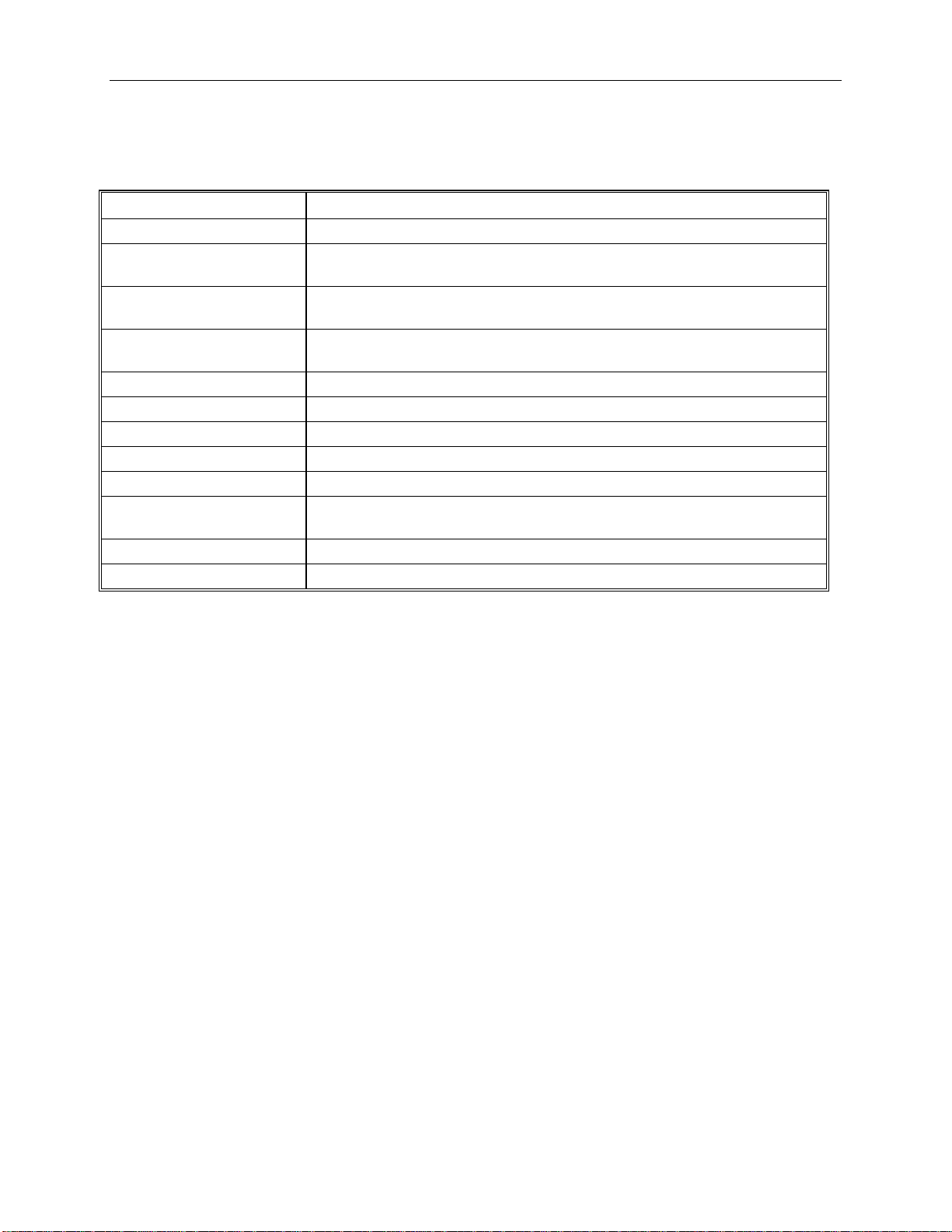
Specifications
Common logger and software specifications are shown below.
Data Security
Operating System
Mi n imu m S yst em
Logger Channels
Unique factory set logger ID. Recording session counter. Password protected
Windows XP, Windows Vista and Windows 7. Compatible with both 32 bit
5MB of free disk space, 800 x 600 screen resolution, 1 free USB port.
User selectable. Disabling channels increases the storage capacity of the other
OM-62 Temperature Humidity Logger
The OM-62 is a self-contained, precision instrument for recording the temperature and relative humidity of the
surrounding environment. The OM-62 can store up to 43,344 temperature samples, or up to 21,672 of both
temperature and relative humidity samples. In addition to Temperature and Humidity, the OmegaLog software
computes and displays the Dew Point Temperature.
The OM-62 logger temperature and relative humidity sensors are open to the air. It is therefore important to ensure
that water does not get into the unit. This is especially important in high humidity situations (90% RH and above)
where water may condense inside the logger, causing damage to the internal electronics.
Warning: Care must be taken to ensure th at the logger is not operating under condensing
conditions. This means that the dew poin t temperature must be below the ambient temperature.
Condensation will damage the humidity sensor and the logger electronics.
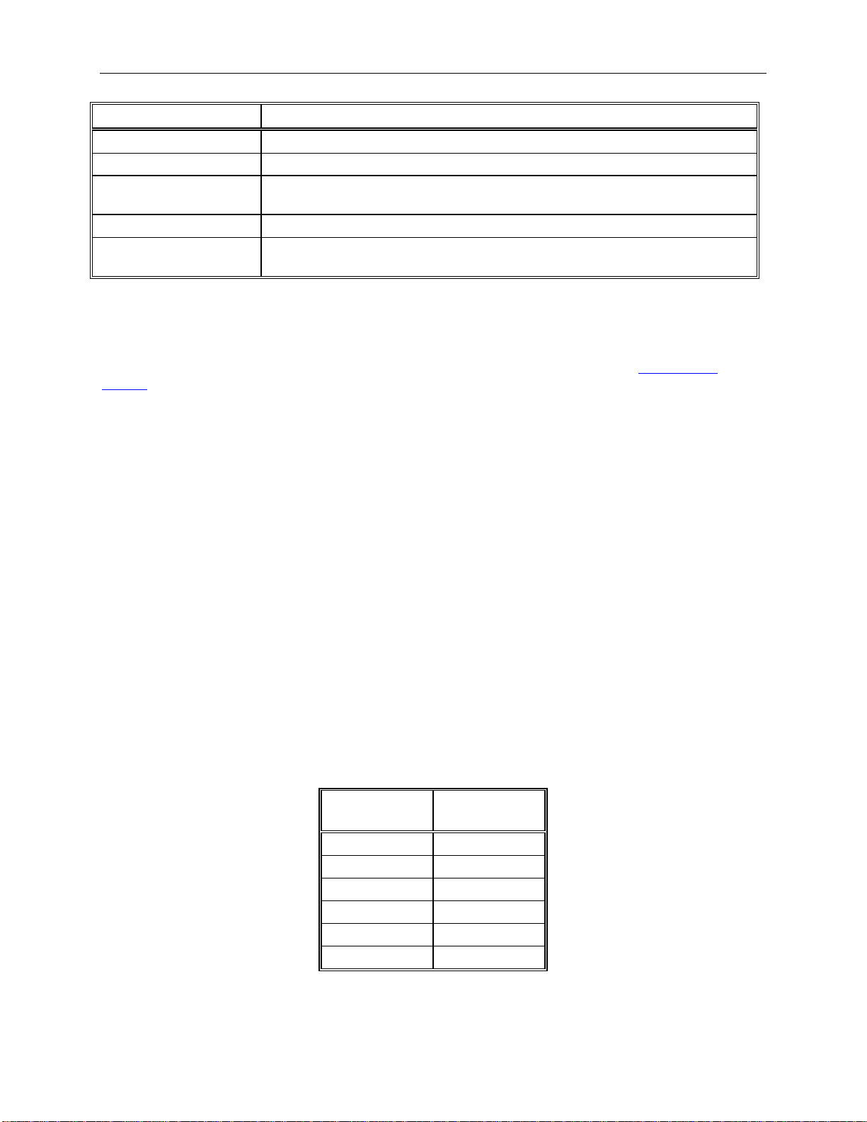
OM-62 Logger Status LED
Pressing the Start/Chec k button makes the LED fla sh a series of flashes to indicate the logger status. The table
below shows the different logger sta te s that the status light can show.
Page 20
OmegaLog User’s Guide Version 1.5x 20/36
Status Light
Logger State
Flashed Green one time
Logging is no t in progress. Data in memory did not exceed the alarm thresholds.
Flashed Red one time
Logging is no t in progress. Data in memory exceeded one of the alarm thresholds.
times
Flashed Red four times
Logging is in progress. Data in memory exceeded one of the alarm thresholds
three times
Interval
1 Second
4 Months
5 Seconds
17 Months
10 Seconds
2.5 Years
30 Seconds
4.5 Years
1 Minute
6 Years
2 Minutes
7 Years
Flashed Green four
Flashed Green-Red
Logging is in progress. Data in memory did not exceed the alarm thresholds
Delayed logging. Logging will start at the user sp e c ified time.
Replacing the OM-62 Battery
The battery level of the OM-62 can be checked using the OmegaLog software, by opening the Logger Status
window
reaches red, it is imperative that the battery is replaced as soon as possible. When the battery level is too low, the
logger will stop logging automatically, resulting in data not being recorded. The OmegaLog software will give you
a warning if you try to start a loggin g session while the battery is low.
To replace the battery follow these steps:
. It is suggested that the ba tte ry is replaced when the battery level reaches yellow. When the battery level
1. Disconnect the logger from the USB cable. Do not replace the battery while the USB cable is
connected!
2. Using a screwdriver, remove the screw in the back of the logger.
3. Remove the logger from the case.
4. Using a pen or a pencil, push the battery out of the casing, then use your fingers to slide the battery out
Avoid using pliers as they will short the batter y.
5. Press and hold the logger button for about 2 seconds. This step removes any extraneous charge
from the logger system. This step is very important. The logger may not operate correctly if this
step is not performed.
6. Slide the new CR2032 battery into the battery case. Make sure that the + indicator on the battery matches
the + indicator on the battery case.
7. When the battery is replaced correctly, the LED will flash a single green flash for about 1 second.
8. Place the logger back in the case and replace the screw.
General guidelines as to how long a batte ry will last is shown in the table belo w. It is assumed that the logger uses a
fresh CR2032 battery, and is setup for continuous logging with rollover enabled.
Logging
Battery Life
Page 21
OmegaLog User’s Guide Version 1.5x 21/36
and dew point.
point alarms are not available
temperature and humidity. Calibration is password protected.
Operating Temperature
-35°F to 160°F (-31°C to 70°C)*
Storage Temperature
-40°F to 170°F (-40°C to 77°C)
Time Accuracy
+/-100ppm @75°F
Relative Humidity Range
0% to 99%RH, non condensing.
Accuracy
Resolution
Temperature Accuracy
+/-1°F (0.5°C)
Temperature Resolution
0.05°F or 0.05°C
Dimensions
3’’ x 1.6" x 0.6’’ (7.6cm x 4.0cm x 1.5cm)
Weight
1.0 oz (23g)
Power Source
3V CR2032 Lithium coin cell battery (Included)
Battery Life (average use)
6 Years
Status Light
Logger State
Flashed Green one time
Logging is no t in progress. Data in memory did not exceed the alarm thresholds.
Flashed Red one time
Logging is no t in progress. Data in memory exceeded one of the alarm thresholds.
Flashed Green four times
Logging is in progress. Data in memory did not exceed the alarm thresholds
Flashed Red four times
Logging is in progress. Data in memory exceeded one of the alarm thresholds
times
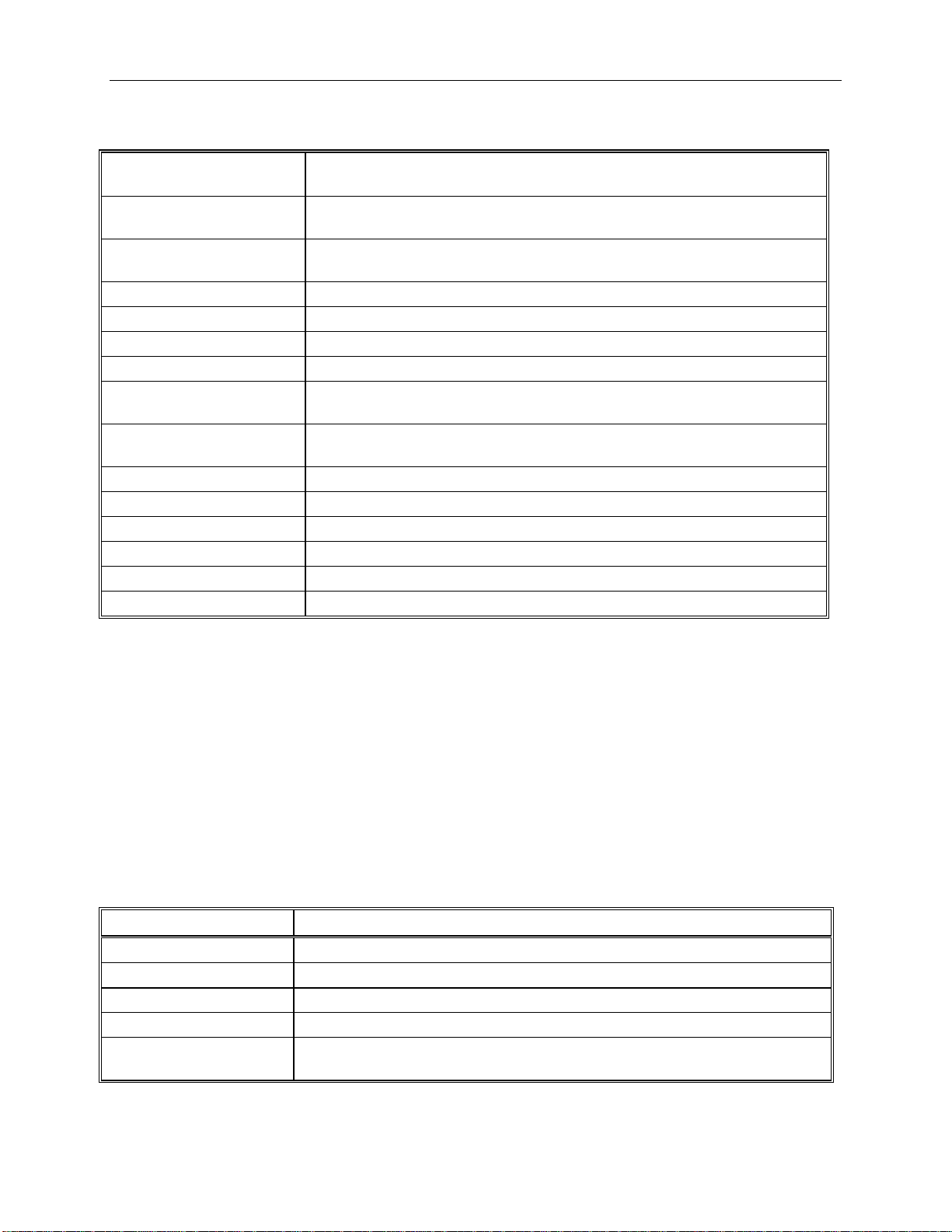
OM-62 Specifications
Sample Point Capacity
Alarms
Calibration
Relative Humidity
Relative Humidity
43,344 points for temperature only. 21,672 points for temperature, humidity
Visual over and under alarm indicator for temperature and humidity. Dew
User single point offset calibra tion is available through software for both
+/- 2%RH, from 10% to 90% RH
0.05%RH
* Lithium batteries do not perfo rm well in very low temperatures. If t he logger is going to be used in temperat ures
below 32°F (0°C), make sure to start with a fresh battery, and check the battery level often.
OM-63 Temperature Logger
The OM-63 is a self-contained, precision instrument for recordi ng the temperature of the surrounding environment.
The OM-63 can store up to 43,344 temperature samples.
OM-63 Logger Status LED
Pressing the Start/Chec k button makes the LED flash a series of flashes to indicate the logger status. The table
below shows the different logger sta te s that the status light can show.
Flashed Green-Red three
Delayed logging. Logging will start at the user sp e c ified time.
Page 22

OmegaLog User’s Guide Version 1.5x 22/36
Interval
1 Second
4 Months
5 Seconds
17 Months
10 Seconds
2.5 Years
30 Seconds
4.5 Years
1 Minute
6 Years
2 Minutes
7 Years
Replacing the OM-63 Battery
The battery level of the OM-63 can be checked using the OmegaLog software, by opening the Logger Status
window
reaches red, it is imperative that the battery is replaced as soon as possible. When the battery level is too low, the
logger will s top logging automatically, resulti ng in data not being recorded. The OmegaLog software will give you
a warning if you try to start a loggin g session while the battery is low.
To replace the battery follow these steps:
General guidelines as to how long a batte ry will last is shown in the table belo w. It is assumed that the logger uses a
fresh CR2032 battery, and is setup for continuous logging with rollover enabled.
. It is suggested that the battery is replaced when the battery level reaches yellow. When the battery level
1. Disconnect the logger from the USB cable. Do not replace the battery while the USB cable is
connected!
2. Using a screwdriver, remove the screw in the back of the logger.
3. Remove the logger from the case.
4. Using a pen or a pencil, push the battery out of the casing, then use your fingers to slide the battery out
Avoid using pliers as they will shor t the battery.
5. Press and hold the logger button for about 2 seconds. This step removes any extraneous charge
from the logger system. This step is very important. The logger may not operate correctly if this
step is not performed.
6. Slide the new CR2032 battery into the battery case. Make sure that the + indicator on the battery matches
the + indicator on the battery case.
7. When the battery is replaced correctly, the LED will flash a single green flash for about 1 second.
8. Place the logger back in the case and replace the screw.
Logging
Battery Life
Page 23
OmegaLog User’s Guide Version 1.5x 23/36
Sample Point Capacity
43,344 temperature points.
Alarms
Visual over and under alarm indicator for temperature.
password protected.
Temperature
Storage Temperature
-40°F to 185°F (-40°C to 85°C)
Time Accuracy
+/-100ppm @75°F
Temperature Accuracy
+/-0.9°F (0.5°C) for the range of 0°F to 120°F (-17°C to 50°C)
Resolution
Dimensions
3’’ x 1.6" x 0.6’’ (7.6cm x 4.0cm x 1.5cm)
Weight
1.0 oz (28g)
Power Source
3V CR2032 Lithium coin cell battery (Included)
use)
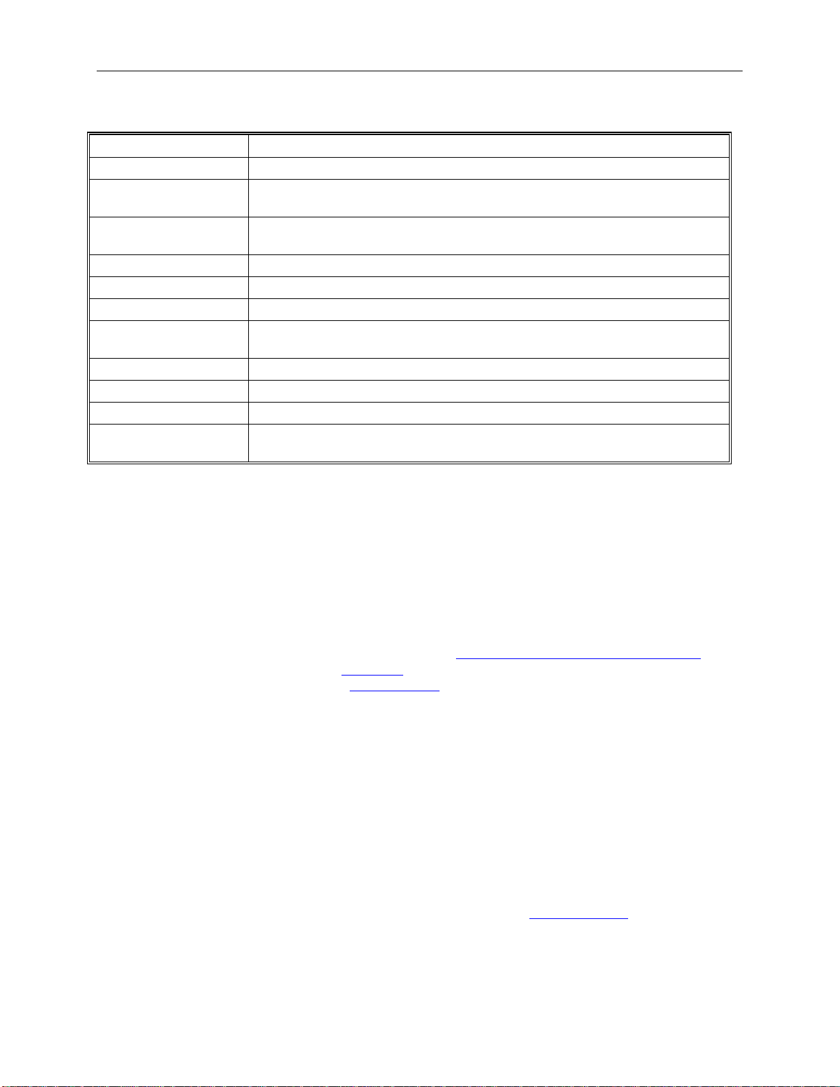
OM-63 Specifications
Calibration
Operating
Temperature
Battery Life (average
* Lithium batteries do not perfo rm well in very low temperatures. If t he logger is going to be used in temperat ures
below 32°F (0°C), make sure to start with a fresh battery, and check the battery level often.
User single point offset calibra tion is available through software. Calib ration is
-40°F to 185°F (-40°C to 85°C)*
0.05°F or 0.05°C
6 Years
OM-DVTH Temperature Humi dity Logger with Display
The DataView OM-DVTH is a self-contained, precision instrument for recording the temperature and relative
humidity of the surrounding environment. The OM -DVT H can store up to 43,344 temperature samples, or up to
21,672 of both temperature and relative humidity samples. In addition to Temperature and Humidity, the unit
computes and displays the Dew Point Temperature.
The OM-DVTH features a display that allows the user to see the
simultaneously. In addition the unit shows,
logged during the current logging session. A
such as the logging rate, the number of samples recorded, the length of the current recor ding and the amount of time
left for recording.
The OM-DVTH temperature and relative humidity sensors are open to the air. It is therefore i mpor ta nt to ensure
that water does not get into the unit. This is especially important in high humidity situations (90% RH and above)
where water may condense inside the logger, causing damage to the internal electronics.
graphically, the temperature and relative humidity data that has been
summary screen shows information about the current logging sess io n,
current temperature, humidity and dew point
Warning: Care must be taken to ensure th at the logger is not operating under condensing
conditions. This means that the dew poin t temperature must be below the ambient temperature.
Condensation will damage the humidity sensor and the logger electronics.
Turning the OM-DVTH On and Off
To conserve battery life, the OM-DVTH will turn itself Off after about 1hour of operation, if the unit is not logging
and no buttons are pushed. The display will go blank and the unit will e nter a
logger uses practically no power, and the battery will last as long as its shelf life (typically 6 years for an alkaline
battery).
In the Power Save mode you can still use all the features of the OmegaLog software to communicate with the
logger, even set the logger for a new logging session. The logger will auto matica lly exit the Power Down mode
Power Save mode. In this mode the
Page 24
OmegaLog User’s Guide Version 1.5x 24/36
when it is set to log.
Another wa y to turn the logger Off is to
To turn the logger On at any time, just p ress any of the l ogger's but tons. The display will come back on and the
logger will operate normally
power down the logger using the OmegaLog software .
OM-DVTH Sample Screen
There are three different screens that the user can switch between, using the View button. The Sample and
Summary screen show the current s tatus of the logger. The Graph screen shows a record of the logged temperature
and humidity samples in memory.
The Sample screen is shown below.
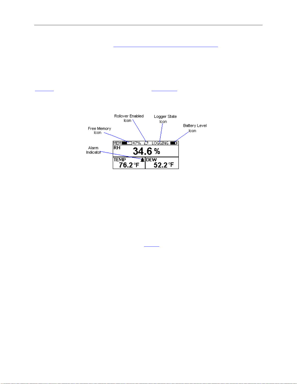
This screen shown the current Relative Humidity, Temperature and Dew Point measurements. The measurements
are updated every two seconds, independent of the device sample rate.
Note: If the user selects only the temperature channel to be logged, the logger will display only the
temperature during logging. Relative Humidity and Dew point will not be displayed. When logging is
finished (either the memory becomes full, or on user command), the logger will once again display all
three measurements (temperature, humidity and dew point).
The icons provide a summary of the current state of the logger.
• MEM: The Memor y bar graph shows the amount of memory used and left in the logger. When logging
starts, the bar graph is empty. It fills up as samples are sto r e d into memory. The percentage display shows
how much me mory is used, a s well.
• Rollover Enabled Icon: This icon shows that
becomes full, the logger will overwrite the oldest data stored in memory. Note that this icon shows that
rollover has been enabled. It does not indicate if rollover has occurr e d.
• Logger State Icon: This icon shows the current state of the logger:
o IDLE: The logger is not logging. The sample display is still being updated, but no data is stored
in logger memory.
o LOGGING: The logger is recording data at a user specified logging rate.
o PRESS START TO LOG: The logger is not re cording data, but has been setup to start logging
when the Start button is pressed. Press and hold the Start button for about 3 seconds to start
logging.
o DELAYED LOGGING: The logger i s not recording data, but has been setup to start logging at a
specific date and time. To see when logging will start, press the View button twice to bring up the
countdown to the start of logging.
• Battery Level Icon: This icon shows the state of the logger batteries. When this icon is down to one bar,
the logger battery should be replaced.
• Alarm Indicator: This icon shows that a channel has entered an alarm state during logging. This is a
"sticky" indicator since once the channel entered an alarm condition, the icon turns On, and stays On even
rollover has been enabled and that once the memory
Page 25
OmegaLog User’s Guide Version 1.5x 25/36
if the alarm condition goes awa y. See the
information on setting a nd using alarms.
Alarm Setup section in the Software User's Guide for more
The OM-DVTH Summary Screen
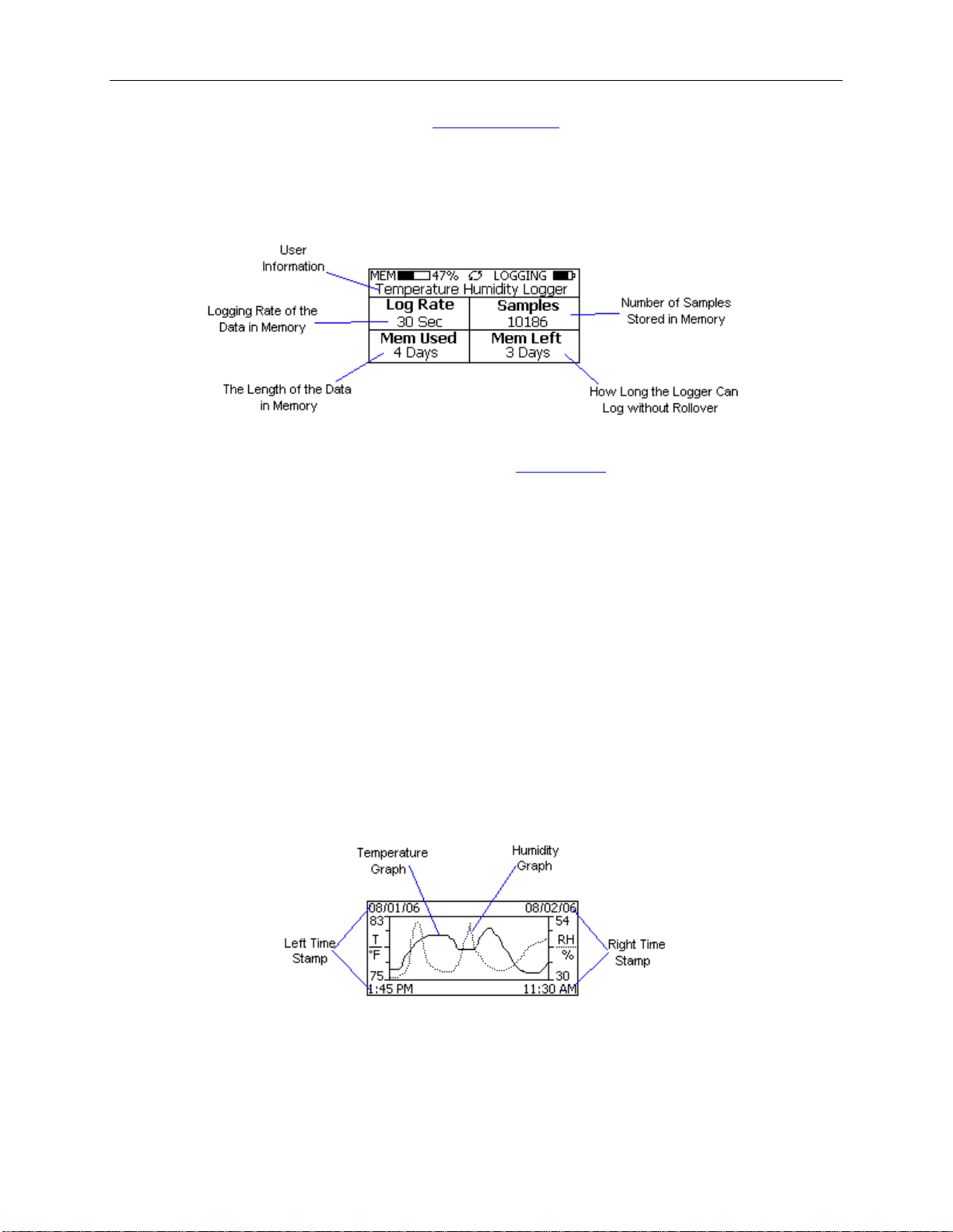
The Summary screen is shown below.
The icons in the summary screen are identical to the icons in the
• The User Information: This 30 character text field is entered through the OmegaLog setup software, and
can be any text that describes the logger
• Logging Rate: Is the rate at which the data in memory was logged at.
• Samples: Shows the number of samples stored in memory. If a rollover has occurred this number will
show the maximum number of samples that can be stored in the logger, and will not change, even though
the logger may be logging.
• Mem Used: Shows the length (in days, hours , minutes or seconds) of data currently stored in memory. If a
rollover has occurred, this number will show the maximum length of data that can be stored in memory, for
a given sample rate. If a rollover has occurred, this number will not change even though the logger may be
logging.
• Mem Left: Shows the length (in days, hours, minutes or seconds) of data the logger can record without
overwriting currently recorded data (record without a rollover). If a rollo ver has oc c urred, this number will
show 0 Sec, even though the logger may still be logging.
Sample screen. The Summary screen shows:
OM-DVTH Graph Screen
The OM-DVTH is capable of displaying the logged data graphically to show temperature and relative humidity
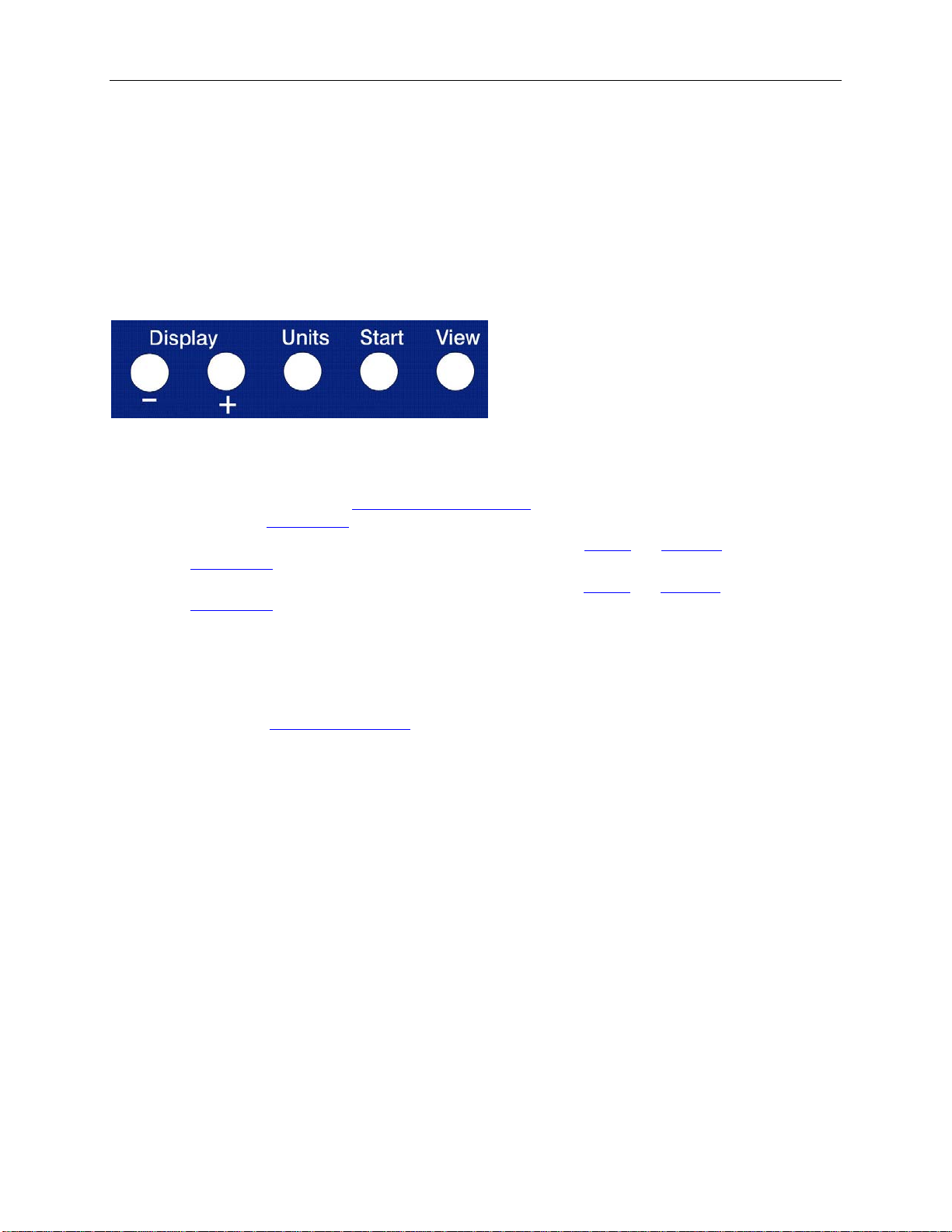
trends. The OM-DVTH Graph screen is shown below.
This screen shows the graph of the samples stored in logger memory. The temperature graph is shown with a solid
line. The temperature axis is on the left. The humidity graph is shown with a dotted line. The humidity axis is on
the right. The graph time stamps are shown on the left and on the right, above the axis.
For instance, in the graph above, data collected between August 1st, 2006, 1:45 PM and August 2nd, 11:30 AM is
shown. The graph temperature range is between 75 ° F and 83 ° F. The relative humidity range is between 30%RH
Page 26
OmegaLog User’s Guide Version 1.5x 26/36
and 54%RH.
When in the graph screen, you can use the Display - and Display + buttons to shift the graph left and right ,
respectively. Pressing and holding the Start button, while in the graph screen, re turns the graph view to the last
sample take n.
When the logger is loggi ng, the graph display is automatically updated as new sa mples are logged.
OM-DVTH Buttons
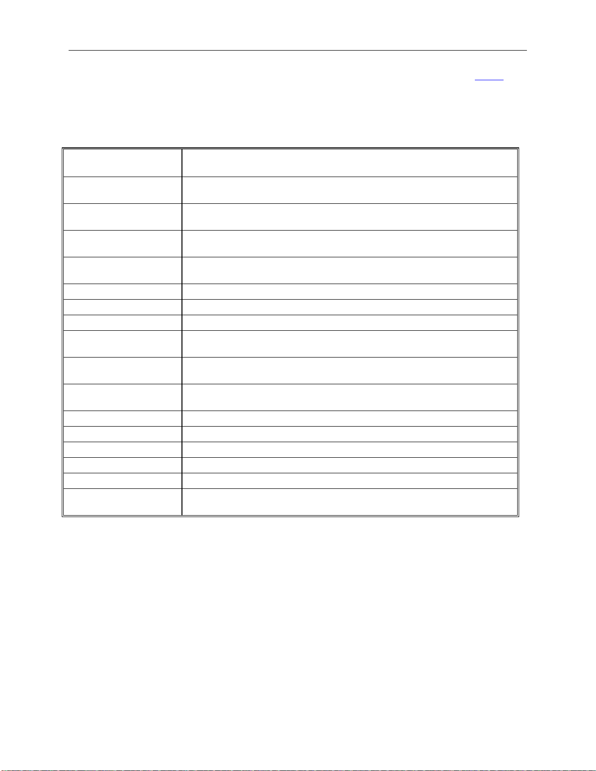
The OM-DVTH has five buttons as shown below.
• Units: Use this button to change the displayed units between ° F and ° C.
• View: Use this button to change the displayed screen.
• Start: If the logger has been
logging. In the
• Display +: Use this button to increase the screen contrast when in
Graph screen this button shifts the graph to the right.
the
• Display -: Use this button to decrease the screen contrast when in
Graph screen this button shifts the graph to the left.
the
Graph screen, pressing and holding this button re turns the vie w to the last sample logged.
setup to start on button press, press and hold the Start button to begin
Sample and Summary screens. When in
Sample and Summary screens. When in
Replacing the OM-DVTH Battery
The OM-DVTH uses three AA type alkaline or lithium batteries. Using rechargeable Ni-MH batteries is not
recommended. The battery level of the OM-DVTH is shown on the screen, or can be checked using the OmegaLog
software, by opening the
reaches 1 bar on the display, or in the yellow zone in the OmegaLog software. When the battery indicator is empty,
or reaches red in the OmegaLog software, it is imperative that the battery is replaced as soon as possible. When the
battery level is too low, the logger wil l sto p logging automatically, resulting in data not being recorded. The
OmegaLog software will give you a warning if you try to start a logging session while the battery is low.
To conserve battery power, the OM-DVTH will shutdown automatically, when not logging, after about one hour of
operation. To turn the lo gger back On, just press any button. The logger can r un while logging continuously for one
year on a single set of three AA alkaline batteries.
To replace the batteries follow these steps:
1. Disconnect the logger from the USB cable. Do not replace the battery while the USB cable is
connected!
2. Using a screwdriver, remove the 4 screws in the back of the logger.
3. Carefully remove the back case. Be very careful not to pull on the battery wires.
4. Remove the three used AA batteries.
5. Press and hold any logger button for about 2 seconds. This step removes any extraneous charge
from the logger system. This step is very important. The logger may not operate correctly if this
step is not performed.
6. Insert three new AA batteries into the ba tte ry holder. Make sure that the + indicator on the battery matches
the + indicator on the battery case.
Logger Status window. It is suggested that the b a tte ry is replaced when the battery level
Page 27
OmegaLog User’s Guide Version 1.5x 27/36
summary, sample rate, memory used and memory left.
logged data.
dew point.
alarms are not available
temperature and humidity. Calibration is password protected.
Operating Temperature
15°F to 150°F (-10°C to 65°C)
Storage Temperature
-5°F to 160°F (-20°C to 70°C)
Time Accuracy
+/-100ppm @75°F
Range
Accuracy
Resolution
Temperature Accuracy
+/-1°F (0.5°C)
Temperature Resolution
0.05°F or 0.05°C
Dimensions
4’’ x 3.05" x 1.5’’ (10.2cm x 7.7cm x 3.8cm)
Weight
7.0 oz (200g)
Power Source
Three AA batteries (Included)
Off after 1 hour, when not logging. T urn On by pressi ng any button.
7. When the batteries is replaced correctly, the logger should start up automatically and show the
screen.
8. Replace the OM-DVTH back cover and replace the 4 screws.
OM-DVTH Specificati ons
Text Display
Graph Display
Sample Point Capacity
Alarms
Calibration
Relative Humidity
Displays real time temperature, hu midity and dew point. Displays logging
Shows meas urement trends graphical ly. Graph ca n be scrolled through the entire
43,344 points for temperature only. 21,672 points for temperature, humidity and
Visual over and under alarm indicator for temperature and humidity. Dew point
User single point offset calibra tion is available through software for both
0% to 99%RH, non condensing.
Sample
Relative Humidity
Relative Humidity
Battery Life
+/- 2%RH, from 10% to 90% RH
0.05%RH
1 year continuous use, 2 years average use. The logger automatically turns itself
OM-DVT4 Four Temperat ur e Logger w it h Display
The OM-DVT4 is a self-contained, precision instrument for recording up to four temperatures. The OM -DVT4 has
one internal temperature sensor and 3 external sensors. The external sensors are temperature rated between -40°F to
160°F (-40°C to 70°C). The internal senor can operate from 15°F to 150°F (-10°C to 65°C). The OM-DVT4 can
store up to 21,760 points when 4 channels are logging, 29,010 points when 3 channels are logging, 43,520 points
when 2 channels are logging and 87,040 points when a s ingle channel is logging.
The OM-DVT4 features a display that allows the user to see the current temperature for all channels simultaneously,
as well as the temperature difference between channels. In addition the unit graphs two of the chan nels that have
been logged during the current logging session. The two channels shown on the graph are user selectable. A
summary screen shows information a bout the curr ent logging se ssion, such as the logging rate, the n umber of
samples recorded, the length of the curr ent recording and the amount of time left for recor ding.
Page 28
OmegaLog User’s Guide Version 1.5x 28/36
Turning the OM-DVT4 On and Off
To conserve battery life, the OM-DVT4 will turn itself Off after about 1hour of ope r a tion, if the unit is not logging
and no buttons are pushed. The display will go blank and the unit will e nter a
logger uses practically no power, and the battery will last as long as its shelf life (typically 6 years for an alkaline
battery).
In the Power Save mode you can still use all the features of the OmegaLog software to communicate with the
logger, even set the logger for a new logging session. The logger will auto maticall y exit the Po wer Save mode when
it is set to log.
Another wa y to turn the logger Off is to
To turn the logger On at any time, just p ress any of the logger's buttons. The display will come back on and the
logger will operate normally
power down the logger using the OmegaLog software .
Power Save mode. In this mode the
OM-DVT4 Sample Screen
There are a number of different screens that the user can switch between, using the View button. The Sample and
Summary screens show the current status of the logger. The Graph screen shows a record of the logged temperature
samples in memory .
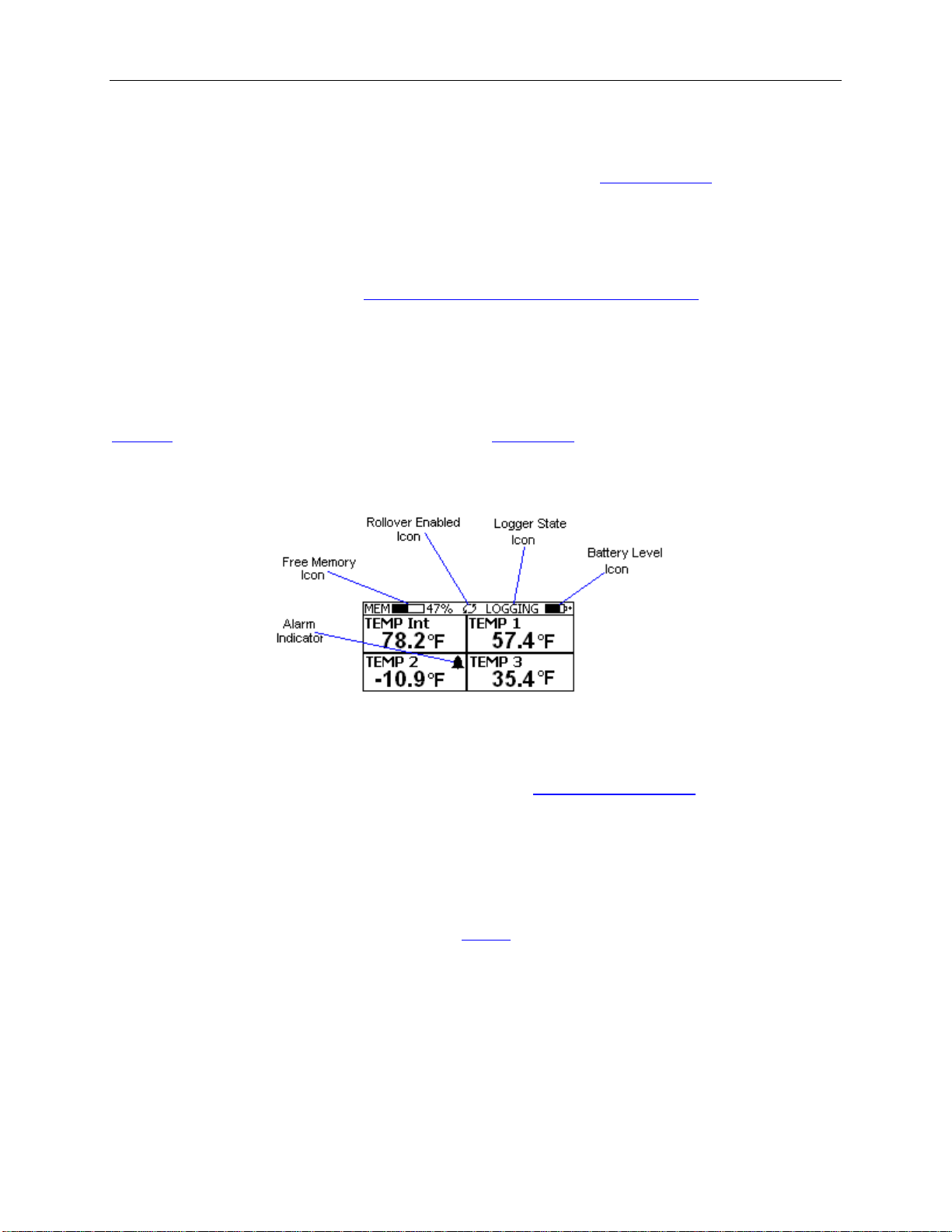
A typical four channel sample screen is shown below.
This screen shown the current temperature measurements. These measurements are updated every two seconds,
independent of the device sample rate.
Note: During logging only the channels that are selected to log will be displayed. For instance, if the user
selected Internal Temperature and Temp 3 for logging, using
Temp 3 will be display during logging. Once logging has finished, all four channels will be displayed
again.
The icons provide a summary of the current state of the logger.
• MEM: The Memor y bar graph shows the amount of memory used and left in the logger. When logging
starts, the bar graph is empty. It fills up as samples are sto red in memory. The percentage display shows
how much me mory is used, a s well.
• Rollover Enabled Icon: This icon shows that
becomes full, the logger will overwrite the oldest data stored in memory. No t e that this icon shown that
rollover has been enabled. It does not indicate if rollover has occurr e d.
• Logger State Icon: This icon shows the current state of the logger :
o IDLE: The logger is not logging. The sample display is still being updated, but no data is stored
in logger memory.
o LOGGING: The logger is recording data at a user specified logging rate.
o PRESS START TO LOG: The logger is not recording data, but has been setup to start logging
when the Start button is pressed. Press and hold the Start button for about 3 seconds to start
rollover has been enabled and that once the memory
the logger setup screen, only Temp Int and
Page 29
OmegaLog User’s Guide Version 1.5x 29/36
logging.
o DELAYED LOGGING: The logger i s not recording data, but has been setup to start logging at a
specific date and time. To see when logging will start, press the View button until the logg ing
countdown is displayed on the scree n..
• Battery Level Icon: This icon shows the state of the logger battery. When this icon is down to one bar,
the logger battery should be replaced.
• Alarm Indicator: This icon shows that a channel has entered an alarm state during logging. This is a
"sticky" indicator since once the channel entered an alarm condition, the icon turns On, and stays On even
if the alarm condition goes awa y. See the
information on setting a nd using alarms.
Alarm Setup section in the Software User's Guide for more
OM-DVT4 Difference Screen
When four channels are selected to log, or when the OM-DVT4 is idle, the unit will display an additional
temperature difference screen. The temperature difference is always displayed between the Internal Channel (Temp
Int) and Cha nnel 1 (Temp 1), and between Channel 2 (Temp 2) and Channel 3 (Temp 3).
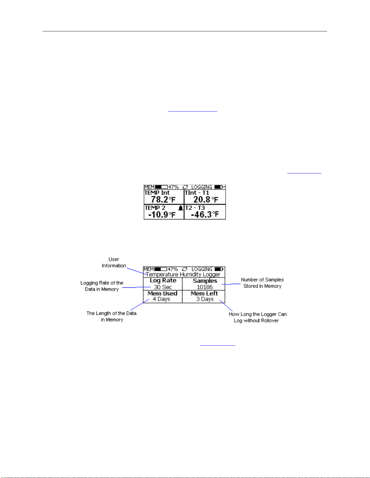
When less than four channels are selected to log, the temperature difference will be displayed on the
sample screen.
OM-DVT4 Summary Screen
The Summary screen is shown below.
The icons in the summary screen are identical to the icons in the
• The User Information: This 30 character text field is entered through the OmegaLog setup software, and
can be any text that describes the logger
• Logging Rate: Is the rate at which the data in memory was logged at.
• Samples: Shows the number of samples stored in memory. If a rollover has occurred this number will
show the maximum number of samples that can be stored in the logger, and will not change, e ven though
the logger may be logging.
• Mem Used: Shows the length (in days, hours, minutes or seconds) of data currently stored in memory. If a
rollover has occurred, this number will show the maximum length of data that can be stored in memory, for
a given sample rate. If a rollover has occurred, this number will not change even though the logger may be
logging.
• Mem Left: Shows the length (in days, hours, minutes or seconds) of data the logger can record without
Sample screen. The Summary screen shows:
Page 30
OmegaLog User’s Guide Version 1.5x 30/36
overwriting currently recorded data (record without a rollover). If a rollover has occurred, this number will
show 0 Sec, even though the logger may stil l be logging.
OM-DVT4 Graph Screen
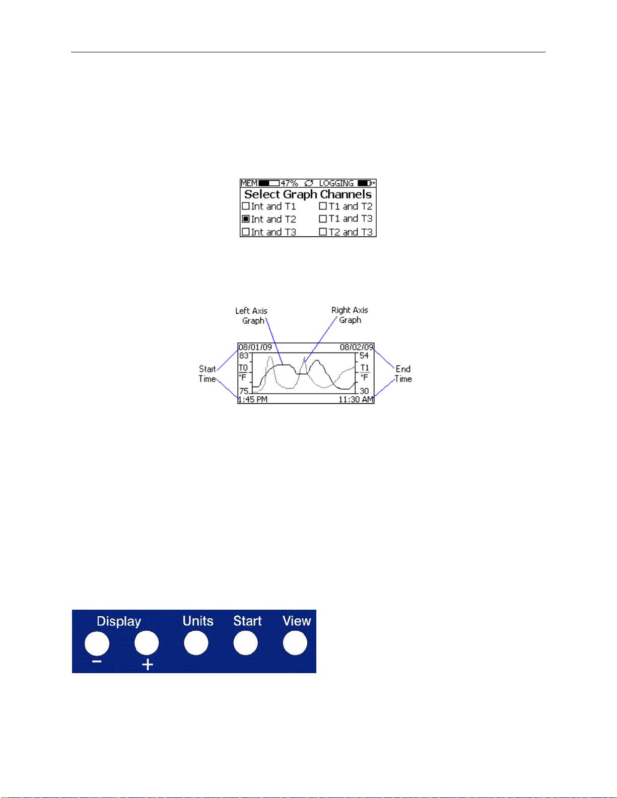
The OM-DVT4 is capable of displaying the logged data graphically to show temperature trends. Two channels can
be displayed at one time. The user can select the graphed channels in the Select Graph Channels screen:
Use the Display + button to select the channels to graph.
Note that only the logged channels (channels recorded in logger memory) can be graphed.
The OM-DVT4 Graph screen is shown below.
This screen shows the graph of the samples stored in logger memory. The solid line corresponds to the left axis.
The dotted line corresponds to the r igh t a xis. The graph ti me stamps are shown on the left and on the right, above
the axis.
For instance, in the graph above, data collected between August 1st, 2009, 1:45 PM and August 2nd, 11:30 AM is
shown. The graph Internal Temperature (T0) range is between 75 ° F and 83 ° F. The T1 range is between 30 ° F
and 54 ° F
When in the graph screen, you can use the Display - and Display + butt ons to shift the graph left and right,
respectively. Pressing and holding the Start button, while in the graph screen, re turns the graph view to the last
sample take n.
When the logger is loggi ng, the graph display is automatically updated as new samples are logged.
OM-DVT4 Buttons
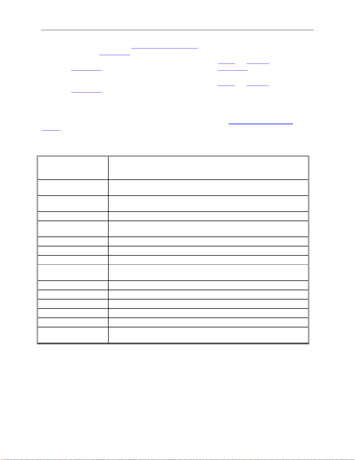
The OM-DVT4 has five buttons as shown below.
• Units: Use this button to change the displayed units between ° F and ° C.
• View: Use this button to change the displayed screen.
Page 31
OmegaLog User’s Guide Version 1.5x 31/36
used and memory left.
logged data. 2 Channels at a time can be graphed (user selectable).
Capacity
for 2 temperatures, 87,040 points for single temperature.
Alarms
Visual over and under alarm indicator for all 4 channels.
temperature channels. Calibration is password protected.
Operating Temperature
15°F to 150°F (-10°C to 65°C)
Storage Temperature
-5°F to 160°F (-20°C to 70°C)
Time Accuracy
+/-100ppm @75°F
Temperature Range
Temperature Accuracy
+/-1°F (0.5°C)
Temperature Resolution
0.1°F or 0.1°C
Dimensions
4’’ x 3.05" x 1.5’’ (10.2cm x 7.7cm x 3.8cm)
Weight
7.0 oz (200g)
Power Source
Three AA batteries (Included)
Off after 1 hour, when not logging. T urn On by pressi ng any button.
• Start: If the logger has been
logging. In the
• Display +: Use this button to increase the screen contrast when in
Graph screen this button shifts the graph to the right. When in Graph Select screen, this button selects
the
the channels to graph.
• Display -: Use this button to decrease the screen contrast when in
Graph screen this button shifts the graph to the left.
the
Graph screen, pressing and holding this button re turns the vie w to the last sample logged.
setup to start on button press, press and hold the Start button to begin
Sample and Summary screens. When in
Sample and Summary screens. When in
Replacing the OM-DVT4 Battery
For instruc tions on how to replace the OM-DVT4 battery, please see the section Replacing the OM-DVTH
Battery.
OM-DVT4 Specifications
Text Display
Graph Display
Sample Storage
Displays real time temperature for all 4 channels. Displays temperature
difference between channels. Displays logging summary, sample rate, memory
Shows meas urement trends graphical ly. Graph can be scrolled through the entire
21,760 points for 4 temperatures, 29,013 points for 3 temperatures, 43,520 points
Calibration
External Probe
Battery Life
User single point offset calibra tion is available through software for a ll
-40°F to 160°F (-40°C to 70°C)
1 year continuous use, 2 years average use. The logger automatically turns itself
OM-DVCV Current Vol t age Logger with Display
The DataView OM-DVCV is a se l f-contained, precision i ns trument for recording AC Current and AC Voltage. The
OM-DVCV can record Voltage up to 600V AC and Current up to 300A AC. The OM-DVCV records true RMS AC
current and AC voltage. I t mea sure s RMS signals up to the 21st harmonic at 60Hz. The OM-DVCV can store up to
21,672 po ints when recording both Voltage and Cur rent. It can store up to 43,344 samples when recording only
Voltage or only Current.
Page 32
OmegaLog User’s Guide Version 1.5x 32/36
The OM-DVCV features a display that allows the user to see measured Current, Voltage and Power (in Watts). In
addition the unit graphs the Current and Voltage that have been logged during the current logging sess i on. A
summary screen shows information a bout the logging session, such as the logging rate, the number of samples
recorded, the length of the recording and the amount of time left for recording.
Connecting the OM-DVCV to Electrical Equipment
Before connecting to any equipment follow these precautions:
• Make sure that the wires are securely attached to the connector and that no uninsulated portion of the wire
is visible after the connection is made.
• Make sure that there is no strain that could pull the leads out of the OM-DVCV connector.
• Make sure that the leads will not interfere with any moving pieces of eq uipment and will not pull loose any
wires or other connections.
To measure the voltage, conne c t the two voltage clip leads to the points at whic h the voltage is being measured.
To measure the current, place the clamp probe around the wire in which the current is being measured.
Electrical connection to any type of operating equipment is Dangerous!
The OM-DVCV leads and current probe should only be co nnected when it has
been determined that the power is off and the equipment is safe to touch.
It is sugges ted that you alway s remove the O M -DVCV voltage leads before
connecting the OM-DVCV to your computer!
If you decide to connect the OM-DVCV to a voltage source while the OM-DVCV is connected to your computer,
make sure to read the "
OM-DVCV Real Time Monitoring" section for instructions.
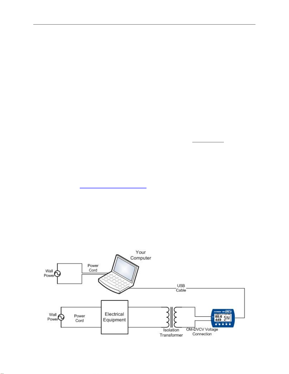
OM-DVCV Real Time Monitoring
Although it is not recommended, it is sometimes necessary to connect the OM-DVCV to a voltage source while the
OM-DVCV is connected to a PC, for instance, if real time monitoring is required. If both the computer and the
voltage source you are connecting to are connected to wall power (as is true in most cases), an isolation transformer
must be used between the voltage source and the OM-DVCV voltage inputs. An isolation tra nsformer does not have
electrical connections between the primary and secondary windings. The recommend ed connection is shown i n the
figure below.
Page 33
OmegaLog User’s Guide Version 1.5x 33/36
If an isolation transformer is not used, the voltage read by the OM-DVCV will not be accurate. The actual reading
may be close to Actual Voltage + Line Voltage, or Actual Voltage – Line Voltage. For instance, if the OM-DVCV is
connected directly to 120V line, without the Isolation Transformer, the reading may be 240V or 0V, depending on
how the computer power supply is wired.
Turning the OM-DVCV On and Off
To conserve battery life, the OM-DVCV will turn itself Off after about 1hour of ope r a tion, if the unit is not logging
and no buttons are pushed. The display will go blank and the unit will e nter a
logger uses practically no power, and the battery will last as long as its shelf life (typically 6 years for an alkaline
battery).
In the Power Save mode you can still use all the features of the OmegaLog software to communicate with the
logger, even set the logger for a new logging session. The logger will automatically exit the Power Save mode when
it is set to log.
Another wa y to turn the logger Off is to
To turn the logger On at any time, just p ress any of the l ogger's but tons. The display will come back on and the
logger will operate normally
power down the logger using the OmegaLog software .
Power Save mode. In this mode the
Ending the Logging Sessi on on t he OM-DVCV
In addition to ending t he logging s ession thro ugh the softwa re, OM-DVCV allows the user the end the logging
session through a series of button presses. To e nd the OM-DVCV logging session using the buttons follow the
procedure below:
1. Press and hold the End button for about 5 seconds. The logger will display the message: Press the + key 5
times quickly to end logging.
2. Release the End button and press the Display + button 5 times in rapid succession. Pressing a ny other
buttons will return the logger to normal operation, without ending the logging session.
3. Logging wil l end and the logger will display IDLE in the
logger state icon.
OM-DVCV Sample Screen
There are a number of different screens that the user can switch between, using the View button. The Sample and
Summary screens show the status o f t he logger. The Graph screen shows a record of the logged samples in memory.
A typical Current and Voltage scree n i s shown below.
This screen shows the present Current and Voltage measurements. These measurements are updated every two
seconds, independent of the device sample rate.
Note: During logging only the channels that are selected to log will be displayed. For instance, if the user
Page 34
OmegaLog User’s Guide Version 1.5x 34/36
selected to log only Voltage, using the logger setup screen, onl y Voltage w ill be di splayed during logging.
Once logging has finished, Current, Voltage and Power will be displayed again.
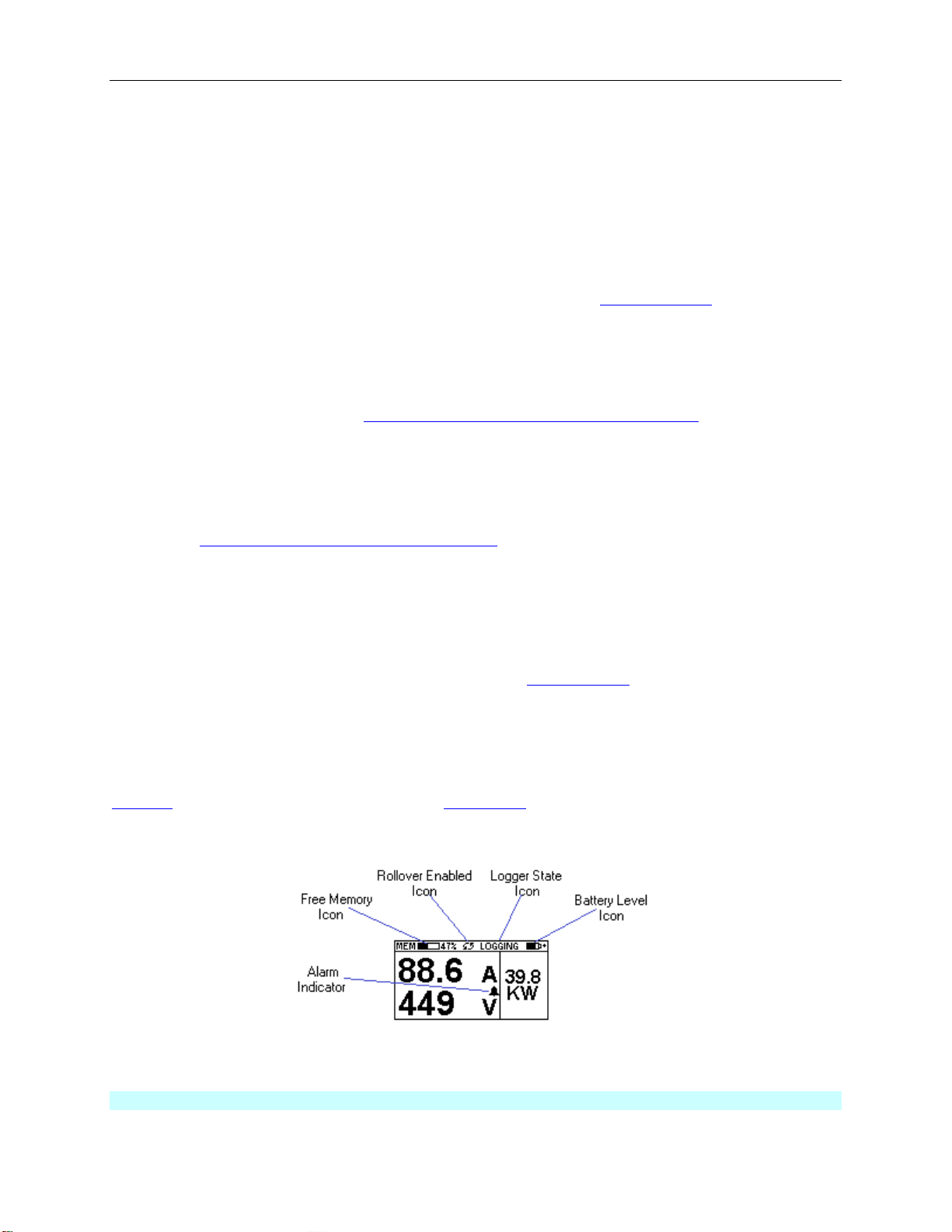
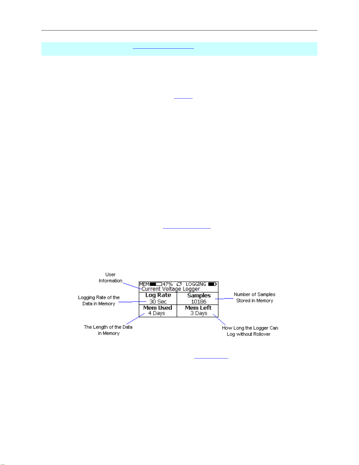
The icons provide a summary of the state of the logger.
• MEM: The Memor y bar graph shows the amount of memory used and left in the logger. When logging
starts, the bar graph is empty. It fills up as samples are stored in memory. The percentage display shows
how much me mory is used.
• Rollover Enabled Icon: This icon shows that
becomes full, the logger will overwrite the oldest data stored in memory. Note that this icon shows that
rollover has been enabled. It does not indicate if rollover has occurr e d.
• Logger State Icon: This icon shows the state of the l ogger:
• IDLE: The logger is not logging. The sa mple display is still being updated, but no d a ta is sto red
in logger memory.
• LOGGING: The logger is recording data at a user specified logging rate.
• PRESS START TO LOG: The logger is not recordi ng data, but ha s been setup to start logging
when the Start button is pressed. Press and hold the Start button for about 3 seconds to start
logging.
• DELAYED LOGGING: T he logger is not recording data, but has been setup to st art logging at a
specific date and time. To see when logging will start, press the View button until the logging
countdown is displayed on the scree n..
• Battery Level Icon: This icon shows the state of the logger battery. When this icon is down to one bar,
the logger battery should be replaced.
• Alarm Indicator: This icon shows that a channel has entered an alarm state during logging. This is a
"sticky" indicator since once the channel entered an alarm condition, the icon turns O n, and stays On even
if the alarm condition goes awa y. See the
information on settin g and using alarms.
rollover has been enabled and that once the memory
Alarm Setup section in the Software User's Guide for more
OM-DVCV Summary Screen
The Summary screen is shown below.
The icons in the summary screen are identical to the icons in the
• The User Information: This 30 character text field is entered through the OmegaLog setup software, and
can be any text that describes the logger
• Logging Rate: Is the rate at which the data in memory was logged at.
• Samples: Shows the number of samples stored in memory. If a rollover has occurred this number will
show the maximum number of samples that can be stored in the logger, and will not change, e ven though
the logger may be logging.
• Mem Used: Shows the length (in days, hours, minutes or seconds) of data currently stored in memory. If a
rollover has occurred, this number will show the maximum length of data that can be stored in memory, for
Sample screen. The Summary screen shows:
Page 35
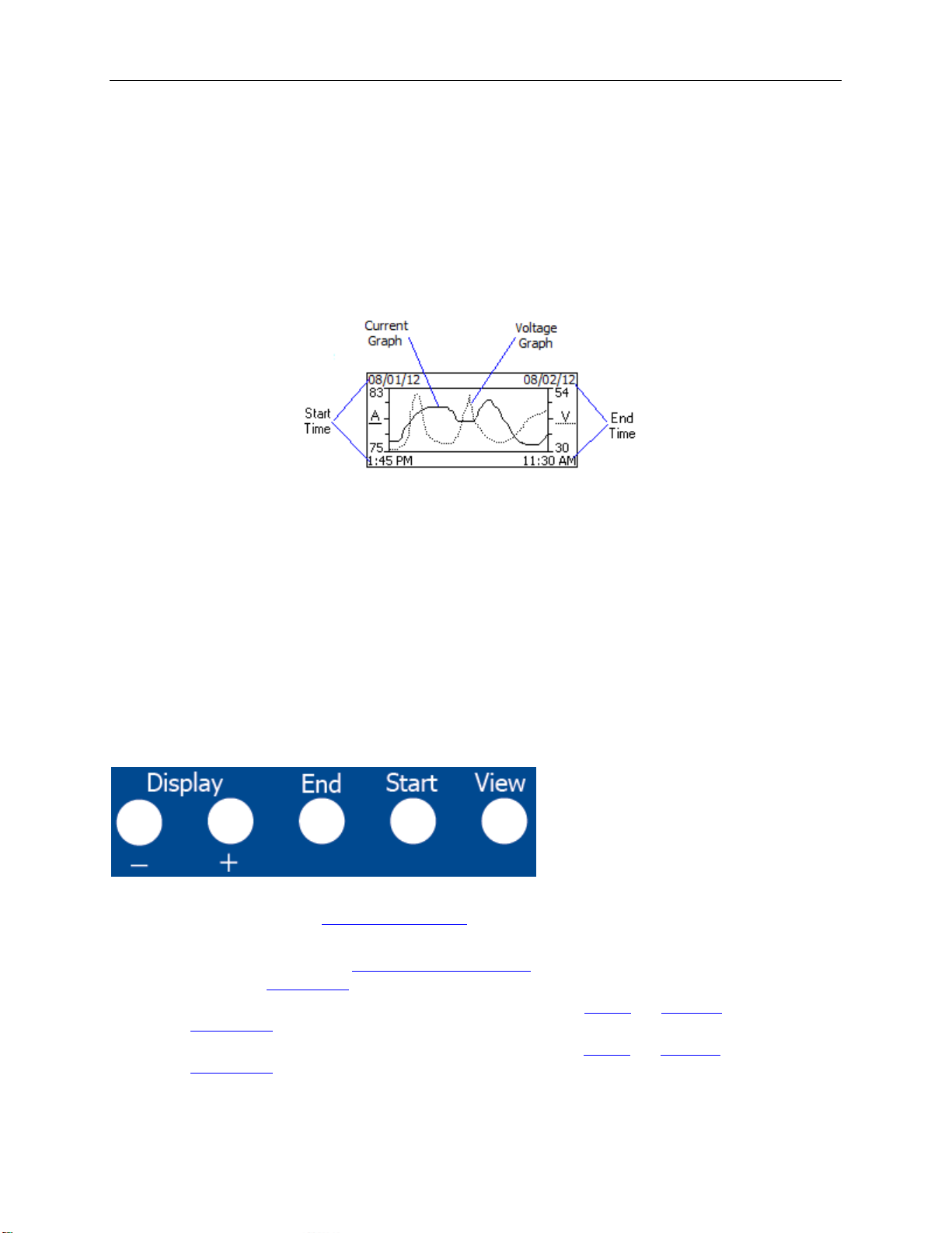
OmegaLog User’s Guide Version 1.5x 35/36
a given sample rate. If a rollover has occurred, this number will not chan ge even though the logger may be
logging.
• Mem Left: Shows the length (in days, hours, minutes or seconds) of data the logger can record without
overwriting currently recorded data (record without a rollover). If a rollover has occurred, this number will
show 0 Sec, even though the logger may still be logging.
OM-DVCV Graph Screen
The OM-DVCV is capable of displaying the logged data graphically to show current and voltage trends. The OMDVCV Graph screen is shown below.
This screen shows the graph of the samples stored in logger memory. The current graph is s hown with a solid line.
The curre nt axis is on the left. The voltage is shown with a dotted line. The voltage is on the r ight. The graph time
stamps are s hown on the le ft and on the right, above the axis.
For instance, in the graph above, data collected between August 1st, 2012, 1:45 PM and August 2nd, 11:30 AM is
shown. The graph current range is between 75A and 83A. The voltage range is between 30V and 54V.
When in the graph screen, you can use the Display - and Display + buttons t o shift the gr aph left and right,
respectively. Pressing and holding the Start button, while in the graph screen, re turns the graph view to the last
sample taken.
When the logger is loggi ng, the graph display is automatically updated as new samples are logged.
OM-DVCV Buttons
The OM-DVCV has five buttons as shown below.
• End: Use this button to
• View: Use this button to change the displayed screen.
• Start: If the logger has been
logging. In the
• Display +: Use this button to increase the screen contrast when in
Graph screen this button shifts the graph to the right.
the
• Display -: Use this button to decrease the screen contrast when in
Graph screen this button shifts the graph to the left.
the
Graph screen, pressing and holding this button re turns the vie w to the last sample logged.
end the logging session.
setup to start on button press, press and hold the Start button to be gin
Sample and Summary screens. When in
Sample and Summary screens. When in
Page 36
OmegaLog User’s Guide Version 1.5x 36/36
rate, memory used and memory left.
logged data.
Sample Point Capacity
43,344 points for current or voltage only. 21,672 points for current and voltage
Measurement Type
True RMS up to the 21st harmo nic at 60Hz
not available
Calibration
No user calibration is available
Operating Temperature
15°F to 150°F (-10°C to 65°C)
Storage Temperature
-5°F to 160°F (-20°C to 70°C)
Time Accuracy
+/-100ppm @75°F
Current Range
1 to 300 Amps AC
Current Accuracy
+/- 1.0 A
Current Resolution
0.2 A
Voltage Range
1 to 600 Volts AC
Voltage Accuracy
+/- 0.4 V
Voltage Resolution
0.2 V
Dimensions
4’’ x 3.05" x 1.5’’ (10.2cm x 7.7cm x 3.8cm)
Weight
7.0 oz (200g)
Power Source
Three AA batteries (Included)
Off after 1 hour, when not logging. T urn On by pressi ng any button.
Replacing the OM-DVCV Battery
For instructions on how to replace the OM-DVCV battery, please see the section Replacing the OM-DVTH
Battery.
OM-DVCV Specifications
Text Display
Graph Display
Alarms
Displays real time current, voltage and watts. Displays logging summary, sample
Shows meas urement trends graphical ly. Graph ca n be scrolled through the entire
Visual over and under alarm indicator for current and voltage. Watts alarms are
Battery Life
1 year continuous use, 2 years average use. The logger automatically turns itself
Page 37

WARRANTY/DISCLAIMER
OMEGA ENGINEERING, INC. warrants this unit to be free of defects in materials and workmanship for a
pe
riod of 13 months from date of purchase. OMEGA’s WARRANTY adds an additional one (1) month
grace period to the normal one (1) year product warranty to cover handling and shipping time. This
ensures that OMEGA’s customers receive maximum coverage on each product.
If the unit malfunctions, it must be returned to the factory for evaluation. OMEGA’s Customer Service
D
epartment will issue an Authorized Return (AR) number immediately upon phone or written request.
U
pon examination by OMEGA, if the unit is fo
charge. OMEGA’s WARRANTY does not ap
including but not limited to mishandling, improper interfacing, operation outside of design limits,
i
mproper repair, o
having been ta
or current, he
co
nditions outside of OMEGA’s control. Components in which wear is not warranted, include but are not
limited to contact points, fuses, and triacs.
OM
EGA is pleased to offer suggestions on the use of its various products. However,
OM
EGA neither assumes responsibility for any omissions or errors nor assumes liability for any
damages that result from the use of its products in accordance with information provided by
OM
EGA, either verbal or written. OMEGA warrants only that the parts manufactured by the
co
mpany will be as specified and free of defects. OMEGA MAKES NO OTHER WARRANTIES OR
REPRESENTATIONS OF ANY KI
TITLE, AND AL
AND FITNESS FOR A PARTICULAR PURPOSE ARE HEREBY DISCLAIMED. LIMITATION OF
LI
ABILITY: The remedies of purchaser set forth herein are exclusive, and the total liability of
OM
EGA with respect to this order, whether based on contract, warranty, negligence,
in
demnification, strict liability or otherwise, shall not exceed the purchase price of the
co
mp onent upon whi ch liability is ba sed. In no event shall OMEGA be lia ble for
co
nsequential, incidental or special damages.
NDITIONS: Equipment sold by OMEGA is not intended to be used, nor shall it be used: (1) as a “Basic
CO
Co
mponent” under 10 CFR 21 (NRC), used in or with any nuclear installation or activity; or (2) in medical
applications or used on humans. Should any Product(s) be used in or with any nuclear installation or
activity, medical ap
as set forth in our basic WARRANTY/DISCLAIMER language, an
OMEGA an
Product(s) in such a manner.
d hold OMEGA harmless from any liability or damage whatsoever arising out of the use of the
r unauthorized modification. This WARRANTY is VOID if the unit shows evidence of
mpered with or shows evidence of having been damaged as a result of excessive corrosion;
at, moisture or vibration; improper specification; misapplication; misuse or other operating
ND WHATSOEVER, EXPRESSED OR IMPLIED, EXCEPT THAT OF
L IMPLIED WARRANTIES INCLUDING ANY WARRANTY OF MERCHANTABILITY
plication, used on humans, or misused in any way, OMEGA assumes no responsibility
und to be defective, it will be repaired or replaced at no
ply to defects resulting from any action of the purchaser,
d, additionally, purchaser will indemnify
RETURN REQUESTS/INQUIRIES
Direct all warranty and repair requests/inquiries to the OMEGA Customer Service Department. BEFORE
RETURNING ANY PRODUCT(S) TO OMEGA, PURCHASER MUST OBTAIN AN AUTHORIZED RETURN
(A
R) NUMBE R F R OM OMEGA’S C U S T OMER SERVICE D E PART M E NT (IN O R D E R TO AVOI D
PROCESSING DELAYS). The assigned AR number should then be marked on the outside of the return
package and on any correspondence.
The purchaser is responsible for shipping charges, freight, insurance and proper packaging to prevent
breakage in transit.
FOR
WARRANTY
following information available BEFORE
contacting OMEGA:
1
. Purchase Order number under which the product
as PURCHASED,
w
2. Model and serial number of the product under
warranty, and
3. Repair instructions and/or specific problems
relative to the product.
OMEGA’s policy is to make running changes, not model changes, whenever an improvement is possible. This affords
our customers the latest in technology and engineering.
OMEGA is a registered trademark of OMEGA ENGINEERING, INC.
©
Copyright 2009 OMEGA ENGINEERING, INC. All rights reserved. This document may not be copied, photocopied,
reproduced, translated, or reduced to any electronic medium or machine-readable form, in whole or in part, without the
prior written consent of OMEGA ENGINEERING, INC.
RETURNS, please have the
FOR NON-WARRANTY REPAIRS,
for current repair charges. Have the following
information available BEFORE contacting OMEGA:
1. Purchase Order number to cover the COST
of the repair
2. Model and serial number of the product, and
3. Repair instructions and/or specific problems
relative to the product.
,
consult OMEGA
Page 38

Where Do I Find Everything I Need for
Process Measurement and Control?
OMEGA…Of Course!
Shop online at omega.com
SM
TEMPERATURE
Thermocouple, RTD & Thermistor Probes, Connectors, Panels & Assemblies
Wire: Thermocouple, RTD & Thermistor
Calibrators & Ice Point References
Recorders, Controllers & Process Monitor s
Infrared Pyrometers
PRESSURE, STRAIN AND FORCE
Transducers & Strain Gage s
Load Cells & Pressure Gage s
Displacement Transducers
Instrumentation & Accessories
FLOW/LEVEL
Rotameters, Gas Mass Flowmeters & Flow Computers
Air Velocity Indicator s
Turbine/Paddlewheel Systems
Totalizers & Batch Controllers
pH/CONDUCTIVITY
pH Electrodes, Testers & Accessories
Benchtop/Laboratory Meters
Controllers, Calibrators, Simulators & Pumps
Industrial pH & Conductivity Equipment
DATA ACQUISITION
Data Acquisition & Engineering Softwar e
Communications-Based Acquisition Systems
Plug-in Cards for Apple, IBM & Compatibles
Datalogging Systems
Recorders, Printers & Plotters
HEATERS
Heating Cabl e
Cartridge & Strip Heaters
Immersion & Band Heaters
Flexible Heaters
Laboratory Heaters
ENVIRONMENTAL
MONITORING AND CONTROL
Metering & Control Instrumentatio n
Refractometers
Pumps & Tubing
Air, Soil & Water Monitor s
Industrial Water & Wastewater Treatment
pH, Conductivity & Dissolved Oxygen Instrument s
M-5117/0115
 Loading...