

Page 1

K9-Mundial-2K9-Mundial-2
K9-Mundial-2
K9-Mundial-2K9-Mundial-2
MA_K9-Mundial-2/REV0 4/01
NONO
NO
NONO
coco
co
coco
TE:TE:
TE:
TE:TE:
verver
ver
verver
This is a This is a
This is a
This is a This is a
..
The prThe pr
.
The pr
..
The prThe pr
a color coa color co
a color co
a color coa color co
“place marker”“place marker”
“place marker”
“place marker”“place marker”
oduction unit hasoduction unit has
oduction unit has
oduction unit hasoduction unit has
verver
ver
verver
..
.
..
Owner's Guide &
Installation Instructions
COPYRIGHT: OMEGA RESEARCH & DEVELOPMENT 2001
Page 2
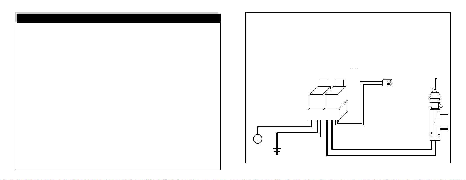
Table of Contents
Owner’s Guide
Introduction ........................................................................................................................................................ 3
Arming the System .......................................................................................................................................... 4-5
System Armed & Activated................................................................................................................................. 6
Disarming the System .................................................................................................................................... 7-8
Remote Panic Operation ................................................................................................................................. 8-9
The Auxiliary Channel ................................................................................................................................... 9-10
Valet Mode & Emergency Override ............................................................................................................. 10-12
The LED Status Indicator ....................................................................................................... ..................... 13-14
Auxiliary Sensor & Prewarning ......................................................................................................................... 15
Silent Arming & Disarming ............................................................................................................................... 16
Programmable Anti-Carjacking Protection................................................................................................... 16-17
Programmable Features.............................................................................................................................. 18-22
How to Program Features ........................................................................................................ ................... 22-23
How to Program Transmitters to the System ............................................................................................... 24-25
Installation Instructions
Installation ........................................................................................................................................................ 25
Wiring Connections ..................................................................................................................................... 45-51
Prewired Plug-in Features ........................................................................................................................... 45-51
Wiring Diagram Overview............................................................................................................................ 26-27
This device complies with part 15 of the FCC Rules. Operation is subject to the following two conditions, (1) This
device may not cause harmful interference and, (2) This device must accept any interference received, including
interference that may cause undesired operation.
The manufacturer is not responsible for any radio or TV interference caused by unauthorized modifications to this
equipment. Such modifications could void the user's authority to operate the equipment.
referred to as the "motor" wires. Even though the cut is made between the
switches, the two sides are still correctly called the "switch" and the "motor" sides,
with consideration of "Primary" and "Secondary" switch; please see the diagram.
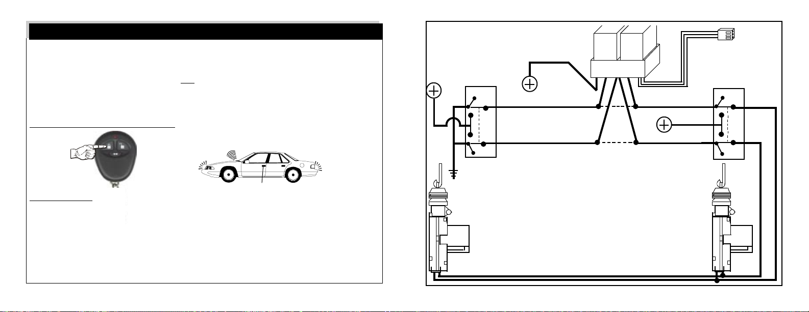
Adding the optional DS-2 Actuator and the DLS and 2 Relays: Some vehicles
have a type of power doorlock system in which mechanically locking and unlocking
the driver's door will operate an electrical switch in the door which supplies voltage
to actuators in the other doors. There is
switch. An indication of this type
of power doorlock system
is when the driver door
key will operate the
Relay
passenger door, but
Relay
the passenger side
will not operate
DLS
the driver door.
no actuator in the driver's door, only a
DLS connector
plugs into
Control Unit
Note: Use this
diagram when
adding actuators
+
to a vehicle not
equipped with
factory power
door locks.
DLS Violet
wire to
12 Volt
DLS Brown and
White wires
connect to
Ground
DLS Green wire to DS-2 Blue wire
DLS Blue wire to DS-2 Red wire
Page 51
Page 3

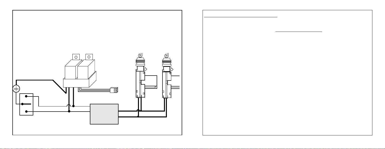
5 Wire Reversal Rest At Ground Systems: This power doorlock system differs
from the negative and positive pulse systems in the fact that there are no relays or
doorlock control unit. In this type of system, the switches themselves supply the
positive voltage directly to the doorlock actuators, and, more importantly, provide
the return ground path. The correct doorlock interface for this type of system is the
optional DLS and 2 relays. The important thing to remember is the wires in this
system
make the connections.
Examine the wires on the back of the switch. Normally five wires will be found. Of
these wires, one will be constant 12 volts positive, regardless of the switch's
position. Two wires will be grounded regardless of the switch's position. Of the two
remaining wires, one will show 12 volts positive when the switch is pushed to "lock",
and the other will show 12 volts positive when the switch is pushed to "unlock".
These two wires are both routed to the doorlock actuators and are connected to
either end of the actuator's motor winding
position, one of these two wires will have 12 volts. This voltage flows through the
wire to the actuator's motor winding, and since the other wire is still
an electrical circuit is completed. When the switch is pushed to the opposite position
the electrical flow is
Notice in the diagram (following page) that the driver's switch is the primary switch
and referred to as the "switch" wires. The wires that go to the secondary switch are
rest at ground,
reversed
which means that the wires must be "opened", or cut, to
.
When the switch is pushed to one
resting at ground
. When the correct wires are found, they must be cut.
Page 50
Introduction
Congratulations on the purchase of your vehicle security system. In learning to
operate your system, please become familiar with these three components:
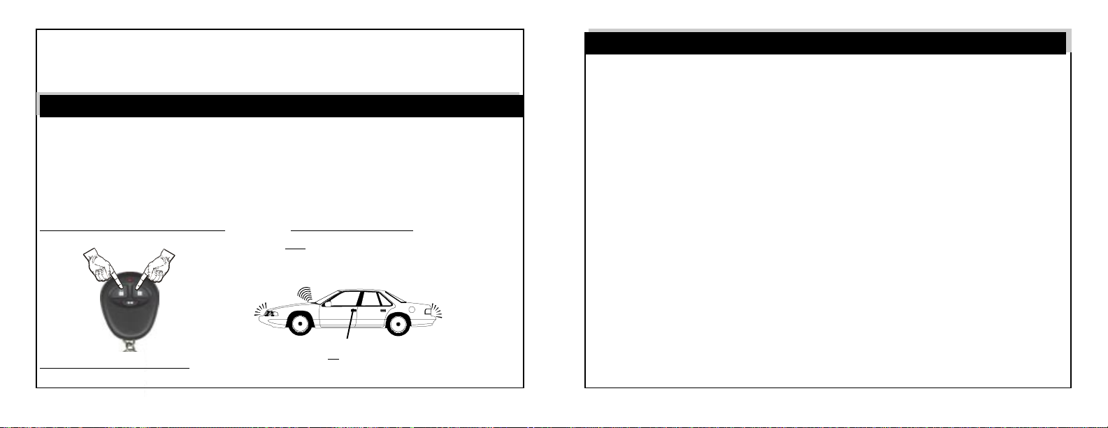
The Transmitter: Each security system comes with two pre-learned transmitters,
but can learn up to 4 different transmitters. Every transmitter has its own unique,
invisible code, which changes with each use. Thus, your transmitter cannot be
duplicated. The transmitter has three buttons: an “Arm/Lock” button, a “Disarm/
Unlock” button and a smaller button which operates an additional output, and which
also can arm and disarm your system silently. Please refer to pages 4-10 for
detailed transmitter operating instructions.
The Valet/Override Switch: This switch can be used to turn “Off” the alarm portion
of the system, including the programmable Automatic Last Door Arming and
Automatic Rearming features, by placing the system into “Valet Mode”. The Valet/
Override Switch can also be used in conjunction with the vehicle’s ignition key to
perform an “Emergency Override” of the system should the transmitter be lost.
Both of these are explained on pages 10-12.
The LED Status Indicator Light: The LED Indicator shows the status of the system and serves as a visual deterrent to break-ins and theft; refer to pages 13-14.
Page 3
Page 4
Arming the System
The system may be "Armed" by one of two methods. The first method involves the
use of a remote transmitter to "Actively" arm the system, provided the ignition
switch is "off" and the system is not in Valet Mode. The second method is a
programmable feature called “Last Door Arming” in which the alarm will “Passively”
or “self” arm.
To Actively Arm the System: Press & Release the “Arm/Lock”
Transmitter Button.
THE SIREN WILL
CHIRP ONCE
THE DOORS WILL LOCK
Upon Arming: • The siren will chirp one time.
(IF CONNECTED)
• The parking lights will flash once.
• The doors will lock. (If an optional interface is connected)
• The starter interrupt will engage.
• The LED Status Indicator will begin to flash slowly.
If a protected zone is open when actively arming using the transmitter, the system will still arm, but it will bypass the open zone until the zone is secured.
Page 4
THE PARKING LIGHTS
WILL FLASH ONCE
+
Driver
Doorlock
Switch
- Ground
Driver
Doorlock
Actuator
Relay
DLS Violet
wire to
DLS
+12 Volts
Unlock
DLS White wire to
Lock wire, "Switch" side.
DLS Brown Wire to
Unlock wire, "Switch" side.
Lock
Cut both Lock and
Unlock wires in car
5 Wire Reversal Rest At - Ground
with optional DLS and 2 SPDT Relays-
See Complete Text On Next Page.
Page 49
Relay
DLS Green wire to Lock
wire, "Motor" side
. +12 Volts
DLS Blue wire to Unlock
Wire, "Motor" side.
DLS connector plugs
into control module.
Passenger
Doorlock
Switch
Unlock
Lock
Passenger
Doorlock
Actuator
+
Page 5
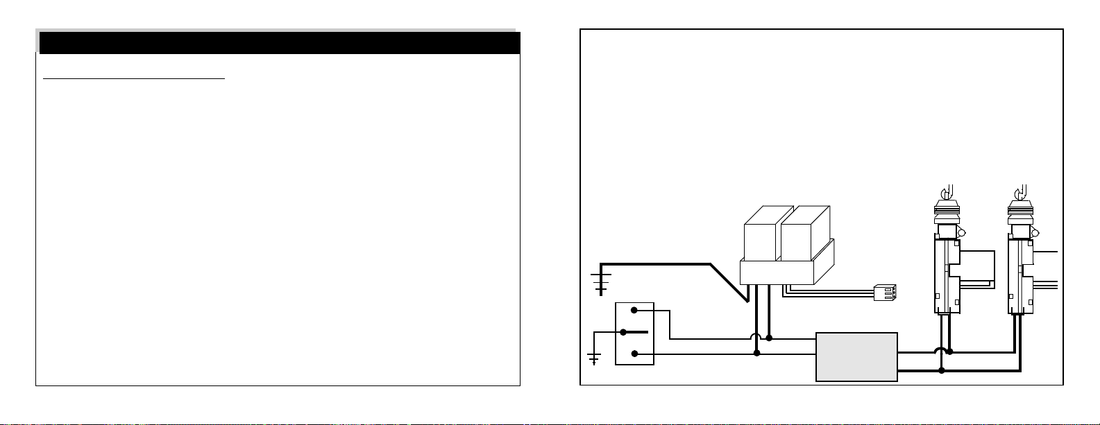
3 Wire +12 Volts Pulse Systems: This power doorlock system is very similar to
the 3 wire - Ground pulse system except the vehicle's doorlock switches use +12
Volts pulses to operate the doorlock relays/control unit. Examine the wires on the
back of the switch. Of the three wires, one will be +12 Volts, regardless of the
switch's position. Of the two remaining wires, one will show +12 Volts when the
switch is pushed to "lock", and the other
will show +12 Volts when
the switch is
pushed to
"unlock".
DLS Violet wire to +12 Volts
To +12
Volts
Door Lock
Switch
DLS Brown & White wires
are not used in this system
DLS Green wire
to Switch Lock wire.
Relay
Relay
DLS
DLS Blue wire to
Switch Unlock wire.
DLS connector
plugs into control
module.
Unlock
-29
Lock
Vehicle's Doorlock
Relay Control Unit
+
+
Page 48
To Passively Arm the System: Turn Ignition Off, Then Open &
Close a Door.
Automatic “Last Door Arming” is a programmable feature which allows the alarm
to arm itself and, if desired, lock the doors upon arming. If “On”, this convenient
feature offers a high level of security since the user does not need to actively arm
the system each time the vehicle is exited. Anytime that the ignition is turned off,
and then a door is opened and closed:
• The siren will chirp one time.
• The LED Status Indicator will begin to flash rapidly.
Thirty seconds later:
• The siren will chirp one time again.
• The LED Status Indicator will begin to flash slowly.
• The starter interrupt will engage.
The alarm is now fully armed. The doors will lock at this time, but only if programmed to do so, and an optional interface must also be installed.
The system can not Last Door Arm if a protected zone is open. Should a vehicle
door be opened during the arming countdown, the countdown will stop and start
over again when the door is closed. “Automatic Rearming” (page 19) is a separate programmable operation similar to Last Door Arming, and should not be
confused with it.
Page 5
Page 6
System Armed & Activated
If the System is Activated:
Regardless of method, once the system is in a fully armed state it monitors all
protected zones, and if an intrusion attempt is detected it will activate, or “trigger”.
An activation consists of the following:
• The doors will immediately relock.
• The electronic siren, or optionally the vehicle’s horn, will start sounding.
• The exterior parking lights will flash on and off repeatedly.
An activation has a 30 (or 60) second duration unless the system is disarmed using
the transmitter or the Valet /Override switch. If all protected zones are secure at
the end of the activation, the system will stop and rearm itself to detect further entry
attempts. If a protected zone is still open at the end of the activation cycle, the
system will continue to reactivate itself, for up to six activated cycles before it resets
itself and ignores the violated zone. If the programmable activated period is 30
seconds, a continuously violated zone will activate the alarm for 3 minutes total
before resetting and ignoring the violated zone. If the programmable activated
period is 60 seconds, the total activated time under the same circumstance would
be 6 minutes. Once the system is activated, it will store a Zone Violation Code,
which described on page 14.
Page 6
3 Wire - Ground Pulse Systems: This power doorlock system is indicated by the
presence of three wires at the switch. Of these, one will show constant - Ground,
regardless of whether the switch is being operated or not (at rest). Of the remaining
two wires, one will show - Ground when the switch is pushed to the "lock" position,
and the other wire will show - Ground when the switch is pushed to the "unlock"
position. With the switch at rest, these two wires will read voltage, usually +12
Volts, but in some cases less. The wires from the switches operate doorlock relays
or a doorlock control unit with built-in relays. The correct connection point is
between the switches and the relays. In most cases, vehicles that have this type
of power doorlock system may be wired direct,
because all that's needed to
Doorlock
Actuators
operate the vehicle's relays
are - Ground pulses.
DLS Violet wire to - Ground
Doorlock
Switch
to Switch Lock wire.
Ground
DLS Green wire
Relay
Relay
DLS
DLS Blue wire to
Switch Unlock wire.
DLS connector
plugs into control
module.
Unlock
Lock
Vehicle's Doorlock
Relay Control Unit
+
+
Page 47
Page 7

Omega sensors are available which detect shock to the vehicle and radar sensors
that can detect motion inside and outside the vehicle. When adding an optional
sensor, follow the installation instructions included with the sensor. After installing,
route the harness and connector from the sensor to the system control module.
Plug the sensor's connector into the module's White 4-pin port marked "Aux.".
Plug-In Power Doorlock Interface Port: This security system features a plug-in
port for an optional doorlock interface. The 3 pin port on the alarm control module
produces a - Ground pulse for lock, a +12 Volts pin
for the optional relay coils only
and a - Ground pulse for unlocking the doors. The doorlock connections needed
will depend upon the type of power doorlocks the vehicle has. The vehicle must
have existing power doorlocks. If not present, power doorlocks may be added to
the vehicle by utilizing one of several Omega power doorlock kits. The vast majority
of power doorlocks are found as three system types: 3 wire - Ground pulse, 3 wire
+12 Volts pulse and 5 wire reversal. The best way to identify a doorlock system is
to examine the doorlock switch's wiring. The following pages will show schematic
diagrams of how to connect an optional DLS (also requires two relays) to these
power doorlock systems. The DLS is a dual relay socket with a harness and
connector to plug into the alarm control module and non-terminated wires to splice
into the vehicle's wiring. The DLS and two relays are the most universal doorlock
interface available. The relays used with it are standard 30 amp single pole, double
throw (SPDT) automotive relays.
Page 46
Disarming the System
To Disarm the System: Press & Release the “Disarm/Unlock”
Transmitter Button.
THE SIREN WILL
CHIRP ONCE
,
THE DOORS WILL UNLOCK
(IF CONNECTED)
Upon Disarm: • The siren will chirp twice. (4 chirps if alarm has activated & reset)
• The parking lights will flash twice. (4 times if alarm has activated)
• The doors will unlock. (If an optional interface is connected)
• The starter interrupt will disengage.
• The LED Status Indicator will turn “Off”, or begin flashing rapidly
if the Automatic Rearming feature is programmed on or flash a
Zone Violation code if the alarm was activated. (page 14)
Safety Disarm: If the system is disarmed while it is activated, it will disarm, but
not unlock the doors. This is the Safety Disarm feature; to unlock the doors in this
situation, simply press the Disarm/Unlock Button again. Should the transmitter be
Page 7
THE PARKING LIGHTS
WILL FLASH TWICE
Page 8
lost, damaged, or its batteries be exhausted, the Valet /Override Switch
vehicle’s ignition key
may be used to disarm the system by performing an
& your
Emergency Override, which is explained on page 10-12.
Remote Panic Operation
Should it be needed in a threatening situation or you feel the need to attract attention, the system can be activated remotely by using the transmitter. Your system
features “Enhanced Panic”, which allows you to activate Remote Panic from either the “Arm/Lock” button or “Disarm/Unlock” button; the former locks the doors
and the latter unlocks the doors when Remote Panic is activated.
To Activate Remote Panic: Press & Hold for 3 Seconds the “Arm/Lock”
Button
OR the “Disarm/Unlock” Button
OR
Hold 3
seconds
Hold 3
seconds
Upon Activating Panic:
• The vehicle’s doors will lock or unlock. (*if an optional interface is connected)
THE SIREN SOUNDS
THE DOORS WILL LOCK LOCK
Page 8
OR UNLOCK*
THE PARKING LIGHTS WILL
FLASH
Prewired Plug-in Features
LED Status Indicator: Mount the LED Status Indicator in a location where it can
easily be seen by the driver, and preferably where it can be seen from outside, as
the LED Status Light provides a level of visual deterrence. A 17/64” (6.5mm) hole
must be drilled, and always check the mounting location for adequate depth. After
mounting the LED Status Indicator, route its connector to the security system
control module and insert it into the Red 2-pin port on the control module.
Valet Switch: Use the self-adhesive to mount the Valet/Override Switch in a
hidden but accessible location. The Valet Switch allows the operator access to
Valet Mode and allows an Emergency Override. The Valet Switch is also part of
the programming operations for encoding transmitters and changing the 18
Programmable Features. After mounting the Valet/Override Switch, route the Blue
connector to the security system control module and insert it into the Blue port on
the control module.
Auxiliary Port For Optional Sensor: This security system features a plug-in port
for an optional sensor device. This port supplies +12 Volts, - Ground output, a Ground instant trigger input, and a - Ground prewarn trigger input. Most Omega
Research and Development, Inc. sensors will plug directly into the control module.
Page 45
Page 9

Also, if selected, the security system will automatically disarm, unlock the doors
and
flash the parking lights twice. The trunk release feature can be operated
anytime with the ignition switch "off", but not when it is "on". Unless the vehicle's
trunk release switch negatively triggers a release relay which draws no more than
250mA, an optional relay must be used.
To +12 Volts or - Ground as needed. In
this drawing, - Ground is needed; in other
applications +12 Volts may be needed.
Gray Wire
87
Security
System
Control
Module
• The siren will sound.
• The vehicle’s exterior parking lights will flash.
Remote Panic can be activated anytime, whether the vehicle’s ignition is turned
on or off, and has a 60 second duration (regardless of the 30 or 60 second activation setting) unless a transmitter is used to stop it. At the end of the 60 second
cycle, the system will reset and be in either the armed state (if activated by the
“Arm/Lock” button) or in the disarmed state (if activated by “Disarm/Unlock”).
To Deactivate Panic: Press & Release either the “Arm/Lock”
OR the “Disarm/Unlock” Button
Release
Switch
To +12 Volts
86 87a 85
30
Release
Solenoid
To
+12
Volts
Wiring an optional Relay for Trunk Release.
CONNECTION: An optional relay is required. Connect the Gray wire to relay pin
85, and connect +12 Volts to relay pin 86. Connect pins 87, 87a & 30 as indicated
in the diagram.
Page 44
Deactivating Remote Panic from the “Arm/Lock” button results in the system being in the Armed state with locked doors. If the “Disarm/Unlock” button is used to
deactivate Remote Panic the system will be in the Disarmed state, with unlocked
doors.
The Auxiliary Channel
The Auxiliary Channel may be used to operate an optional function. Possibilities
include remote trunk release, remote car starting, or an on-demand remote window roll-up interface. Please see your Omega dealer for details on available options.
Page 9
continued next page
Page 10

To Activate the Auxiliary Channel:
Press & Hold the Transmitter
Small Button for 3 Seconds
OPERATE OPTIONAL
CAR-START MODULE
Hold 3
seconds
OPERATE OPTIONAL WINDOW ROLL-UPS
For safety, the Auxiliary Channel cannot be activated if the vehicle's ignition is
"On". If the system is armed when the Auxiliary Channel is used, it will also
disarm; or, there is also has a special programmable feature, Start Mode, which is
designed to allow the addition of an optional remote starter module to start the
vehicle while leaving the system armed (page 20-21). The Auxiliary Channel has
output for as long as the Small Button is held.
OPERATE OPTIONAL
TRUNK RELEASE
Valet Mode & Emergency Override
The Valet/Override Switch can perform two distinct functions: accessing Valet
Mode and performing an Emergency Override of an armed and activated system.
Page 10
the same circuit with pin switches:
Optional
Electronic
Sensor
Note: Use IN4002 diodes.
Trunk
Light
Trunk
Pin
Switch
Hood
Pin
Switch
Security
System
Control
Blue - Ground Instant Trigger Wire.
Module
Diode-Isolating multiple - Ground instant triggers.
Gray Wire - (- Ground Output For Optional Trunk Release): The function of
the Gray wire is to provide an optional output, the primary use being trunk release. Press and hold the small transmitter button for three seconds to activate
this output. When activated the Gray wire will provide a 250mA Negative Ground
pulse for 1 second; or, stay grounded for as long as the Transmitter Small Button
is depressed, for up to 15 seconds. Operating this output can also disarm the
system.
Page 43
Page 11

CONNECTION: Connect the Violet wire to a wire in the vehicle which is common
to all the door pin switches. The correct wire for this type of dome light/door jamb
pin switch system will have +12 Volts present when the doors are opened, and Ground when the doors are closed. The correct wire will show this change when
any of the doors are opened.
Blue Wire - (- Ground Instant Trigger Input): The Blue wire is a - Ground instant
trigger used to detect entry into the hood or trunk area of a vehicle. If the security
system is armed, grounding the Blue will activate it.
CONNECTION: The included pin switches may be installed to provide this trigger
circuit Or, if there are existing switches (example: a light in the luggage compartment or a "Trunk Ajar" light in the dash), the Blue wire may be connected directly,
provided this is a- Ground switching circuit. An indication of such a circuit is the wire
having no voltage present when the hood or trunk is open, and up to +12 Volts when
the hood or trunk is closed. This circuit cannot be used with mercury switch types
of hood or trunk lights. If the vehicle is equipped with a usable trunk or hood circuit,
locate the proper wire and splice the Blue wire directly to the vehicle's wire.
When wiring more than one of the vehicle's circuits and/or additional circuits to
this wire, diode-isolation may be required to maintain each circuit's proper operation. An example would be wiring a hood pin switch and trunk light switch together.
Without isolating, the trunk light will illuminate whenever the hood is raised. Also,
diode-isolation is necessary when combining electronic sensors together, or, in the
Page 42
Valet Mode prevents any active arming, from the transmitter, or passive arming, as
in Last Door Arming. Valet Mode is designed for situations in which it is not
convenient for the alarm portion of the system to be operational; for example during
extended stopovers for vehicle servicing, loaning others your vehicle, maintenance, valet parking, washing, etc. The convenience features such as keyless
entry, the auxiliary channel, and ignition-activated doorlocks can still be operated.
To Enter Valet Mode: Press & Hold the Valet
(System MUST be Disarmed) Switch for 3 Seconds.
- The LED Status Indicator will light solid Red to confirm Valet Mode. Now the
system cannot become armed.
The vehicle's ignition may be "On" or "Off" when entering Valet Mode.
To Exit Valet Mode: Simply Press & Release the
Valet Switch.
- The LED Status Indicator will turn off to confirm that the system has exited
Valet Mode and returned to a “standby” mode. Normal arming operations may
be resumed.
Again, the vehicle's ignition may be "On" or "Off" when exiting Valet Mode.
Page 11
Page 12

To Disarm the Security System Without The Transmitter:
123456789012
123456789012
123456789012
123456789012
123456789012
123456789012
123456789012
123456789012
123456789012
123456789012
123456789012
123456789012
123456789012
123456789012
Valet Mode can only be achieved with a disarmed system. If the system is armed,
and in the event that the transmitter is lost, damaged, or its batteries have become
exhausted, the Valet /Override Switch
disarm the system by performing an Emergency Override:
Step 1: With the system in the armed condition, enter the vehicle via the driver's
door (be aware that the alarm will activate when the door is opened).
Step 2: Using your key, turn the vehicle’s ignition to the "On" position.
Step 3:
Within 5 seconds, Press the Valet/Override Switch.
-The activated system will instantly disarm.
Note: When the Valet/Override Switch is pressed, when the system disarms
releasing the switch will place the system in standby mode. Holding the switch for
3 seconds further after the activated system disarms will place the system into
Valet Mode, preventing further arming. Once overridden, the disarmed system
may still be placed into Valet Mode as described on the previous page.
& your vehicle’s ignition key
THEN WITHIN
5 SECONDS
Page 12
may be used to
Also be aware of vehicles which diode-isolate each door. Typically, this is usually
encountered with dash displays that indicate individual doors being ajar. The
proper wire to connect to in this type of system is the common wire which is routed
to the dome light itself.
Violet Wire - (+12 Volts Door Trigger Input): The Violet wire's functions are
identical to the Green Door Trigger wire, with the sole exception that it is an open
door input to the control module for vehicles having
+12 Volts
door pin switches.
For a description of the Violet
wires complete effects
upon the system's
operations, please
Dome
Light
Typical Positive
Dome Light System.
see the Green
wire's description.
Driver
Pin
Switch
This is
the correct
trigger wire.
Ignition Key Warning.
To - Ground
To +12 Volts
Passenger
Pin
Switch
Page 41
Page 13

Opening a door during Automatic Rearming will also suspend that feature. If the
system has been programmed to lock and unlock the doors with the ignition switch
being turned "on" and "off", an open door will cancel the automatic locking or
unlocking.
CONNECTION: Connect the Green wire to a wire in the vehicle which is common
to all the door pin switches. The correct wire in this type of dome light/door jamb
pin switch system typically has no voltage present and will also show - Ground when
the doors are opened, and also up to +12 Volts when the doors are closed. The
correct wire will show this change when any of the doors are opened. If the vehicle
has delay dome lights, remember to take this into account when testing the wire.
If the car has a delay dome light the system can be armed from the transmitter, and
will start protecting the Green wire circuit when the dome light turns off. In Last Door
Arming mode, the system arms 30 seconds after the delay dome light turns off. The
diagram illustrates a basic negative courtesy light system.
If the pin switch is mounted in the metal structure of the vehicle, and the dome light
goes out when the switch is removed, suspect a grounding-type dome light system.
If the switch is mounted in plastic, a constant ground wire will also be present. While
the traditional pin switch is mounted in the front door jamb area, also be aware that
many vehicles utilize other types of switch devices to operate the interior lights.
Some imports have a sliding type of switch and many have the pin or sliding
switches in the rear door jamb area.
Page 40
The LED Status Indicator
The Red LED Status Indicator visually shows the status of the system and also
provides a high level of visual deterrence. The Red LED Status Indicator Light is
normally mounted in a location where it can be easily seen by the driver, as well
as from outside the vehicle.
Security System Status: The primary function of the Red LED Status Indicator
Light is to indicate the normal operating status of the security system:
Off = The system is disarmed and not performing any automatic functions.
On Constant = The system is in the Valet Mode.
Flashing Slow = The system is fully Armed.
Flashing Fast = The system is Last Door Arming or Automatic Rearming.
Automatic Transmitter Verification: For the first 10 seconds after the vehicle’s
ignition is turned "On", the LED Status Indicator will flash a number of times equal
to the number of transmitters which are programmed in the system’s memory and
which can operate the security system. This indication can be from 1 Flash /pause
up to 4 Flashes /pause, as the system can be operated by just one, or as many as
four remote transmitters. A related feature, Unauthorized Transmitter Alert, warns
you of recent transmitter programming, and protects your system from unauthorized
transmitters being coded to operate it your without your knowledge.
Page 13
Page 14

Zone Testing & Zone Violation: Are related visual indicators, via the LED Status
Indicator; the first shows currently violated zones while the system is disarmed,
and the second, should the system be activated, shows which zone caused the
activation after the fact. These are the codes for both operations:
1 Flash /Pause = is the current sensing zone circuit.
2 Flashes /Pause = is the hood or trunk zone circuit.
3 Flashes /Pause = is the door zone circuit.
4 Flashes /Pause = is the sensor zone circuit, including Prewarning Detection.
Zone Testing operates while the system is disarmed, and shows if a protected
zone is in a violated state. In using Zone Testing, for example, while the system
is disarmed, whenever a door is open the LED Status Indicator will flash 3 times
between pauses. Should multiple protected zones be violated at the same time,
all will be shown in sequence.
Zone Violation operates if the system has been armed, and then activated. During
the activation, the LED Status Indicator will flash the Violation, and then revert to
the normal slow flash when the system rests itself, then, upon disarming, the LED
will change to flash the Violation Code, and will continue to do so until the ignition
switch is turned “On”. Should multiple activations occur during a single armed
period, up to four Zone Violations will be shown upon disarming.
Page 14
Green Wire - (- Ground Door Trigger Input): The Green wire's function is an
open door input to the control module for vehicles having
- Ground switching
door
pin switches. This circuit has effects on many security system operations, the
primary being the activation of the system (sounding the siren and flashing the
parking lights) if it is in an armed state. If the Last Door Arming features is utilized,
closing the door will cause the Last Door Arming sequence will begin, and which
will be suspended if a door is reopened.
Note: The Driver Pin Switch often will have an
extra wire that goes to the Ignition Key Warning. This circuit will trigger the security sys-
only from the driver's door; this is the
tem, but
incorrect activation wire.
Driver
Pin
Switch
Typical - Ground Type
Dome Light System.
Dome
Light
To +12 Volts
This is the correct trigger
wire. Connection may be
made at any point.
Passenger
Pin
Switch
Page 39
Page 15

12345
12345
12345
12345
12345
12345
12345
12345
12345
12345
4
4
4
4
4
4
4
4
4
Connection Hints for either Single or Double Circuit Systems.
Auxiliary Sensor & Prewarning
3 Suggested
Parking Light
Dash Lights
Connections:
Do not connect to
Dimmer
the dimmer circuit!
Damage to the control unit or vehicle
can occur!
Parking Lights
Red/White Wire - (+ or - Flashing Light Input): This wire supplies + 12 Volt or
- Ground to the White wires for when the system flashes the parking lights. This
wire is pre-connected to +12 Volts in the main wiring harness- if connection
to - Ground is needed, cut and connect as needed.
CONNECTION: Connect to + 12 Volt or - Ground as needed; this is determined
when testing the vehicle’s parking light wire.
Junction
Block
Page 38
White
Wire
10 Amp
Security
System
Control
Module
Head
Light
Switch
Rear Body Harness
23
23
Parking
23
23
23
Lights
23
23
23
23
Auxiliary Sensor: This security system is equipped with a plug-in port for an
optional sensor to increase the effectiveness of the system. The comprehensive
line of optional sensors offered is comprised of impact sensors, glass tampering
sensors, and microwave/radar sensors which can detect motion inside and
outside the vehicle. Your Omega dealer can provide details on the complete line
of sensors and help determine which sensor or sensors are best suited for your
needs. Currently many sensors feature dual zone capability, which take advantage
of the security system’s prewarning circuit.
Bypassing the Auxiliary Sensor: If desired, the system may be armed, but
without the auxiliary sensor being part of the system’s protection. Upon arming,
immediately after the single arming confirmation chirp, simply press and release
the Transmitter Small Button; the system will chirp the siren once again to confirm
that the sensor is bypassed. When the sensor has been bypassed, it will not
activate the alarm, nor will it cause a Prewarning Detection.
Prewarning Detection: This circuit requires connection to a dual zone sensor or
detection device. When the sensor’s prewarn zone is triggered the security system
will respond by siren burst followed by a series of chirps, which altogether lasts
about 2 seconds.
Page 15
Page 16

Silent Arming & Disarming
4
4
4
4
4
4
4
4
4
Connecting directly to Left & Right Parking Lights.
Should you wish to arm or disarm the system without the confirmation chirps, simply
press and release the Transmitter Small Button
twice. Using the Silent Arm/Disarm
operation simply reverses the armed/disarmed status of the security system- if the
system is disarmed when the double Transmitter Small Button signal is received,
it arms; should the system be armed when the double signal is received, it will
disarm.
Programmable Anti-Carjacking Protection
The system is equipped with three levels of programmable Anti-Carjacking
protection. The Anti-Carjacking operation may be activated by the ignition, a
combination of the ignition and an open door, or the transmitter. These three forms
of Anti-Carjacking protection are programmable features, which are as received
configured “Off”.
First Level:
If programmable feature #14 is “On”, the Anti Car-Jacking operation may be
activated by pressing and holding the transmitter’s Disarm/Unlock Button and
Small Button together for 4 seconds while the ignition is “On”.
Anti-Carjacking activated using the transmitter:
Page 16
Right Parking Lights
23
Security
System
Control
White Wires
7.5 Amp
7.5 Amp
Head
Light
Switch
23
23
23
23
23
23
23
23
Module
Left Parking Lights
will backfeed the parking lights through the rheostat or illumination control module,
and cause damage to the vehicle or the system’s control module. Also, if the White
wire is shorted, the system's control module will be damaged. Some vehicles have
a parking light relay which is triggered by a - Ground circuit wire from the headlight
switch. When installing the system in these cars, connect the White wires to the
vehicle’s switch wire and simply connect the system’s Red/White wire to - Ground.
Flashing the headlights is not recommended- halogen headlights are not designed
to be rapidly turned on and off.
Page 37
Page 17

airbag circuit with a standard test light can cause the Airbag to deploy!
Connect the test light clip to - Ground, and probe the wire. If the horn sounds
when probed, a direct connection may be made. If not, use the following diagram
to configure an optional relay. When the control module is configured for (-) Horn
output, exceeding its .25 Amp capability will cause damage to the control module.
White Wires - (+12 Volts Flashing Light Outputs): These are +12 Volts outputs for exterior flashing light confirmation and to attract attention to the vehicle if
the security system is activated.
CONNECTION: Many vehicles have separate left and right side parking lights.
When left & right parking lights are on separate circuits, simply connect one White
wire to each parking light circuit. If the vehicle has a single parking light wire,
connect both of these wires to the vehicle's parking light circuit. The parking light
wire or wires can usually be found at the following locations: at the headlight switch,
at the fuse/junction block, or in the rear body harness in the driver kick panel. The
correct wire or wires will typically show +12 Volts when the headlight switch is in the
"Parking Light" and "Head Light" positions (sometimes - Ground is found). When
such a wire or wires are located, be sure to also test that it is non-rheostated: while
metering the wire, operate the dash light dimmer control. The correct wire will show
no change in voltage when the dimmer is operated. Do not attempt to flash the
parking lights by connecting the White wire to a rheostated (dimmer) circuit! This
Page 36
Second Level: Anti-Carjacking activated by a door:
If programmable feature #15 is “On”, the system will initiate the Anti-Carjacking
operation every time a vehicle door is opened and closed while the ignition is “On”.
Third Level: Anti-Carjacking activated by the ignition:
If programmable feature #16 is “On”, the system will initiate the Anti-Carjacking
operation every time the vehicle’s ignition is turned “On”.
Once the Anti-Carjacking process has begun, the user has 63 seconds to press
the Valet/Override Switch in order to cancel the process. If not cancelled, at 55
seconds the siren will begin to chirp for 8 seconds to alert the user that the system
is about to enter into an activated condition. If the Anti Car-Jacking process is not
cancelled before the 63 second countdown expires, the system will fully activate.
In the activated condition the siren/horn will sound, the parking lights will flash,
and at 95 seconds the starter interrupt will engage. Once the system is activated
in the Anti-Carjack mode, the transmitters will NOT stop the operation, nor will the
system reset automatically. Once it is fully activated, the Anti-Carjacking
operation can only be deactivated by:
First Step: Turning the vehicle’s ignition “Off”.
Second Step: Turning the vehicle’s ignition back “On”.
Third Step: Within 5 seconds Pressing the Valet/Override Switch.
Page 17
Page 18

Programmable Features
The system has 18 programmable features which allow the system to be customized to suite many individual needs. The following pages provide a brief explanation for each feature, and notes its factory default setting. If the feature is not an
“on or off” type feature, the transmitter buttons’ functions in programming mode are
noted. Otherwise, pressing the Arm/Lock Button turns the feature “on”; pressing
the Disarm/Unlock Button turns the feature “off”.
Default Factory Setting
• =
1.
Current Sensing: (•On / Off)
- Enables the system to be activated if armed should the system detect a
voltage spike in the vehicle’s electrical system.
2. Current Sensing Activation Delay: (3 Seconds / •3 Minutes)
- Allows option of a longer delay before activation by current sensing can occur.
This is for use in vehicles with equipment, such as cooling fans, which stay
on after the ignition has been turned off.
3. Last Door Arming: (On / •Off)
- Configures the system to automatically arm itself 30 seconds after the last
Page 18
Optional Relay wiring diagram.
To vehicle's
horn wire.
To +12 Volts.
30
86 87a 85
87
Connect to +12 Volts or
- Ground as needed
to operate the horn.
Brown wire
from control
module.
the horn switch. Typically, a "clicking" sound from the vehicle can heard as the
horn button is pressed, and released, which confirms the presence of an existing
horn relay. Yet another alternative is to consult a wiring schematic of the vehicle
in question to determine if an existing horn relay is present. The least desirable
testing method is the use of a standard +12 Volt test light.
CAUTION! Avoid the
airbag circuit! This is one of the few uses left for a standard test light in a modern
vehicle; use a digital multimeter (DMM) to identify the horn wire first. Probing an
Page 35
Page 19

pins of the 3-pin standup; this is the “H”-marked side of the standup. The standup
and jumper are shown in the Wiring Diagram Overview on pages 26-27. Upon
completion of all wiring connections, consult the Operator’s Guide section of this
manual and program feature #7 for the “Pulsed Horn” audible output setting.
CONNECTION: The Brown wire may be connected directly to the vehicle's horn
switch wire, provided the circuit operates with .25 Amp of current or less. First,
ensure that the vehicle’s horn operates with the ignition switch “off”; if not, an
optional relay and the “direct to horn” method is needed. If the horn sounds when
the ignition if “off”, the next step is to locate the vehicle’s horn switch wire to
determine the presence of an existing horn relay.
circuit!
wire will show +12 Volts normally, and no voltage when the horn is being sounded.
Once the vehicle's horn wire is identified, the electrical switching load must be
determined.
The most direct method is to cut the wire and measure the switching load with a
digital multimeter (DMM). Connect the meter’s Black lead to the cut wire from the
switch, and its Red lead to the cut wire to the horn. Set the meter to its highest
scale first, then press the horn switch to obtain the switching load reading. If the
results are a switching load of .25 Amp (250 milliamperes, or mA), then the control
module’s Brown wire may be connected directly to the vehicle’s horn switch wire.
Other alternative testing methods include disconnecting the horns, then operate
The target wire is typically found around the steering column; the correct
CAUTION! Avoid the airbag
of the vehicle’s doors is closed.
4. Doors Lock With Last Door Arming: (On / •Off)
- Adds the automatic locking of the vehicle's doors to the previous feature.
5. Automatic Rearming: (On / •Off)
- Configures the system to automatically rearm itself 90 seconds after it has
been disarmed by the transmitter.
6. Doors Lock With Automatic Rearm: (On / •Off)
- Adds the automatic locking of the vehicle's doors to the previous feature.
7. Steady Siren Output Or Pulsed Horn Honk Output: (•Siren / Horn)
- Allows the selection of a constant output to sound the electronic siren or a
pulsed output to properly sound the vehicle's horn. If programming, press the
Transmitter Arm/Lock Button for the Steady Siren setting or press the Disarm/
Unlock Button for the Pulsed Horn setting.
8. Ignition Controlled Door Lock: (•On / Off)
- Configures the system to lock the vehicle's doors when the ignition is turned
on.The following feature controls unlocking, and these features will still
operate when the system is in Valet Mode.
Page 19Page 34
Page 20

Ignition Controlled Door Unlock: (•On / Off)
9.
- Configures the system to unlock the vehicle's doors when the ignition is turned
off.
System Activation Cycle Duration: (•30 / 60 Seconds)
10.
- Configures the system’s activation duration cycle to be either 30 seconds or
60 seconds. If programming, press the Transmitter Arm/Lock Button for the
30 Second setting or press the Disarm/Unlock Button for the 60 second setting.
Double Unlock Pulse: (On / •Off)
11.
- Configures system to change the single unlock output pulse into a double
unlock pulse. Some newer vehicles require a double pulse to unlock the
doors; when needed this feature saves the expense of optional parts.
Open Door Bypass Alert: (On / •Off)
12.
- Configures the system to chirp the siren 3 times upon arming, instead of 1
time, to warn the user if a door is still open.
Auxiliary Channel Disarms System Or Engages Start Mode: (•Disarms /
13.
Start Mode)
- This unique feature changes certain aspects of the system’s Auxiliary
Channel’s operation so that it is more compatible with optional remote starter
Page 20
Mounting The Siren: Find a location in the engine compartment away from the
extreme heat of the engine and manifold. A suitable location will offer a firm
mounting surface, will also allow sound dispersion out of the engine compartment,
and not be accessible to a thief. The last point is most important; it is advisable to
seek a location for the siren which requires removal of engine compartment
components, such as the battery, for example, to access the siren. This greatly
reduces the “defeat-ability” of the security system. The siren must be pointed
downward to avoid moisture collecting inside it and to enhance sound dispersal.
The siren’s wires should be carefully routed so as to be not easily detectable, and
to ensure that the wires will not interfere with any moving parts in the engine
compartment or underdash areas.
CONNECTION: The Brown wire must be connected directly to the siren's Red
wire, and the siren's Black wire is connected to - Ground, which may be to any
clean, bare metal point of the vehicle's chassis. The use of an existing grounding
point is a good location. Do not configure the control module’s 3-pin standup
jumper for “(-) Horn” and connect the Brown wire to the siren’s Black wire.
Using The Vehicle’s Existing Horn: This will require that the control module be
configured for “(-) Horn” and that programmable feature #7 be changed from
“Steady Siren” to “Pulsed Horn. To change the Brown wire’s polarity from the “as
shipped” configuration of +12 Volts, locate the shorting jumper next to the main
wiring harness marked “H/S”. Remove this jumper, and reinstall it on the two left
Page 33
Page 21

Connect the starter disable socket's Red wire to the ignition switch side, and its
White wire to the starter solenoid side. Be sure that good, solid electrical connections are made as this generally is a high amperage circuit. Connect the security
system's Orange wire to the Orange wire of the starter disable socket. Note: If
the Orange wire touches 12 volts positive directly or has more than a 500mA
ground load, the circuit will be damaged.
Brown Wire - (Audible Output): The Brown wire is the system’s audible output.
It is capable of being configured for either +12 Volts or Negative output by a standup
and jumper, and it can be programmed to be a steady output or pulsed output in
the Features Programming Mode. When this output is configured +12 Volts it is a
high amperage output to drive an electronic siren; configured Negative it is a low
amperage output to operate a relay to sound the vehicle’s existing horn. Typically, the siren configuration is programmed as steady, and the horn configuration
is programmed as pulsed.
Using The Siren: Confirm that the control module is configured for its “as shipped”
configuration of +12 Volts. The control module has 3-pin standup with shorting
jumper next to the main wiring harness connector; ensure that the attached jumper
is installed on the right two pins, in the “S”-marked position. This standup and
jumper are shown in the Wiring Diagram Overview on pages 26-27.
Page 32
units. When this feature is utilized, instead of disarming the system when the
Auxiliary Channel is activated, the system does not disarm. Additionally,
some of the system’s sensory zones are bypassed to prevent false activation
due to the remote starting operation. When this feature is set for the Start
Mode, and the Auxiliary Channel is activated, the system will bypass the
current sensing and sensor zones if the system is armed. This allows a
remote start module to start the vehicle without activating the system. The
door and trunk zones remain active, and if violated will trigger the system and
turn the vehicle’s engine off. If programming, press the Disarm/Unlock Button
for Start Mode or the Unlock/Disarm Button for Disarm.
Transmitter Activated Anti-Carjacking: (On / •Off)
14.
- This feature’s operation is explained on pages 16-17.
Door Activated Anti-Carjacking: (On / •Off)
15.
- This feature’s operation is explained on pages 16-17.
Ignition Activated Anti-Carjacking: (On / •Off)
16.
- This feature’s operation is explained on pages 16-17.
Confirmation Chirp: (•On / Off)
17.
- This feature allows the arm and disarm confirmation chirps to be turned off.
Page 21
Page 22

When this feature is turned off, exceptions will be chirps during programming
and the single chirp produced when the system arms by Last Door Arming
and Automatic Rearming.
1 or 2 Button Arm/Disarm: (1 Button/•2 Button)
18.
- This feature controls how the transmitter operates the security system.
Having this feature on the “2 Button” setting has the system operating in a
"dedicated button for arming and dedicated button for disarming" fashion. The
"2 Button" setting is the correct one to be used with the included transmitters.
If this feature is set for “1 Button”, a single transmitter button will alternate
arming and disarming the system with each press of that button. This type of
operation is also described as a "single button toggle" for the arming and
disarming of the system. Optional transmitters are available for best use of
this feature. For your reference, if this feature is changed to the “1 Button”
setting, the included transmitters’ Arm/Lock Button will arm and disarm the
system, the Disarm/Unlock Button will operate the Auxiliary Channel, and the
Small Button will not operate anything.
How to Program Features
Starter Disable Socket Red wire
to the Ignition Switch side of the
cut Starter wire.
Ignition
Switch
Cutting the vehicle's
Starter wire will leave
two sides- the Ignition
Switch side and the
Starter Solenoid side.
87a
87
86
C O I L
Socket
Orange
Wire
Starter Disable Socket
White wire to the Starter
Solenoid side of the cut
Starter wire.
30
85
Security
System
Control
Module
Control
Module
Orange wire
Starter
Solenoid
The 18 programmable features, explained in the previous pages, are very easily
programmed by a procedure using the ignition key, Valet/Override Switch, and
Page 22
Configuring a Starter Disable using the Socket & Relay.
Page 31
Page 23

Orange Wire - (Negative Output For Optional Starter Interrupt): The Orange
wire is for a starter disable socket and relay. The function of this wire is to provide
a 500mA - Ground Output whenever the security system is in an armed state. This
output supplies - Ground to one side of the relay's coil. The other side of the relay
coil will be supplied with +12 Volts from the ignition switch, but
switch is turned to the "start" position. If this occurs, the coil will energize, activating
the relay, which in turn will open the starter circuit. The starter interrupt prevents
the vehicle from starting only if the alarm is armed (including while the alarm is
activated), and will draw current from the vehicle's electrical system only if an
attempt is made to start the vehicle.
CONNECTION: To interrupt the vehicle's starter circuit, the starter wire must be
located and cut. It is recommended that this connection be done as close to the
ignition switch as possible. Use a voltmeter, not a test light, to find the correct wire,
which is the wire from the ignition switch to the starter solenoid.
only if the ignition
CAUTION! Avoid
the airbag circuit! Improper use of a test light can cause deployment of the airbag,
which may result in bodily injury! Test lights can also damage on-board computers
and associated sensors.
The starter wire will read +12 Volts only when ignition key is in "start" position
(cranking the engine). Cut this wire at a suitable location. Confirm that this is the
correct wire by turning the ignition switch to the "start" position. The starter should
not engage.
Page 30
transmitter. To access Features Programming Mode:
Step 1: Turn the vehicle's ignition "On" then "Off".
Step 2: Within 10 seconds of turning the ignition "Off", press the Valet/Override
Switch 5 times. The system will sound a siren burst, then a single chirp
confirming entry to Features Programming Mode.
Step 3: Within 7 seconds of entering Features Programming Mode, press the
Valet/Override Switch the number of times equal to the number of the
feature to be programmed. The system will repeat the feature number
with same number of siren chirps.
Step 4: After the system acknowledges the feature to be programmed, press
either the Transmitter Arm/Lock Button to turn the feature on (the system’s
response will be 1 chirp), or the Disarm/Unlock Button to turn the feature
off (the system’s response will be 2 chirps).
To program more features, simply repeat Steps 3 and 4. If seven seconds expire
without any programming activity the system will automatically exit Features Programming Mode. Turning on the ignition switch will also exit the system from
Features Programming Mode; in either case the system signals the exit with two
siren bursts.
Page 23
Page 24

How to Program Transmitters to the System
Whenever a transmitter, new or existing, is programmed to the system, all existing codes are erased for security. So all of the transmitters which are to operate
the system, which can be up to four, must be programmed at the same time.
Step 1: Turn "On" the vehicle's ignition.
Step 2: Within 10 seconds press the Valet/Override Switch 5 times. The system
responds with 1 siren burst to confirm Transmitter Programming Mode.
Step 3: Within 10 seconds, press the Small Button on each transmitter to be pro-
grammed. The response to each is 1 and 1, 1 and 2, etc., chirps.
If 17 seconds expire without any programming activity the system will automatically exit Transmitter Programming Mode. Turning off the ignition switch will also
exit the system from Transmitter Programming Mode; in either case the system
signals the exit with 1 long siren chirp.
Unauthorized Transmitter Alert: For the next 48 hours after transmitter
programming, every time the vehicle’s ignition is turned “On”, the system will emit
a series of siren chirps, and the LED Status Indicator will show the number of
programmed transmitters for 90 seconds instead of 10 seconds. As the instructions
above shows, programming extra transmitters to any vehicle security system is
Page 24
the system will revert to the state it was in previously. The Red wire also supplies
+12 Volts to the built-in relay for flashing the parking lights.
CONNECTION: Connect the Red wire to a source which has +12 Volts at all times.
Ensure that this source +12 Volts which is stable in all ignition key positions.
Connection locations can be at the supply wire at the ignition switch, the supply wire
behind
any other security system wire behind a fuse. Also, please note that connecting
directly to the battery's Positive terminal will expose this connection to failure due
to a corrosive environment. The source connection must have at least a 15 Amp
capacity at all times.
Yellow Wire - (+12 Volts Ignition Input): The Yellow wire is an ignition "on" input
to the security system. This connection is critical to the proper operation of many
of the security system's operations.
CONNECTION: This wire supplies +12 Volts to the control module whenever the
ignition switch is "on". This connection should be made at the ignition switch
harness, to the primary ignition circuit. Primary ignition has 0 Volts when the ignition
key is in the "Lock", "Off" and "Accessory" positions; and +12 Volts in the "Run" and
"Start" positions. Locate the correct wire at the ignition switch harness and securely
splice the Yellow wire to it. This connection is critical to the proper operation of
"Enhanced 3rd Channel Operation".
the fuse block or the fuse/junction block.
Page 29
Never
just insert the Red wire or
Page 25

Wiring Connections
Black Wire - (- Ground Input):
which completes the circuitry and allows the security system to operate.
CONNECTION: Using the correct sized crimp-on ring terminal, connect the Black
wire to the metal frame of the vehicle, preferably using an existing machinethreaded fastener. Make sure that the ring terminal attached to the Black wire has
contact with bright, clean metal. If necessary, scrape any paint, rust or grease away
from the connection point until the metal is bright and clean. If the control module
has an insufficient ground connection, the security system can find partial ground
through the wires that are connected to other circuits, but the alarm will not function
correctly, giving the impression of a defective control module. The system can
partially work, so a bad ground wire connection would be suspected. In some
cases the alarm could arm and disarm properly -but not function
correctly otherwise.
The Black wire attached to the control module is the antenna wire.
connect this wire to anything or the transmitter's range will be reduced or
eliminated. Stretch the Black antenna wire out and as high as possible for the best
operating range.
Red Wire - (+12 Volts Input): The Red wire's function is to supply Constant
+12 Volts to the security system. When +12 Volts is first applied to the Red wire,
The Black wire's function is to supply - Ground,
Do not
Page 28
easy; the exclusive patented Unauthorized Transmitter Alert feature protects
against someone programming their own transmitter to operate your system.
Installation
Mounting The Main Control Module: The Main Control Module contains the
electronics necessary for the security system's operation. Always mount this
module in the vehicle's interior compartment, in a secure location that is not easily accessible. Ensure that moisture, vibration and temperature extremes are
minimized. Acceptable locations may include mounting behind the dash, behind
the glovebox or other interior panels.
Mounting The Siren: Find a location in the engine compartment away from the
extreme heat of the engine and manifold. A suitable location will offer a firm
mounting surface, will also allow sound dispersion out of the engine compartment, and not be accessible to a thief. The siren must be pointed downward to
avoid moisture collecting inside it and to enhance sound dispersal.
Wiring Connections: The security system's wires should be securely connected
to the appropriate vehicle wires with the proper terminals, connectors, or by
soldering and insulating with quality vinyl electrical tape or heat shrink tubing. All
wiring should be carefully routed to avoid the possibility of chaffing or otherwise
being damaged. Make all required connections, then plug the harnesses into the
control module.
Page 25
Page 26

K-9 Mundial-2
By Omega Research & Development
Door Lock Port
Siren / Horn Jumper
LED Status
Indicator
Page 27
Sensor Port
Valet/Override
Switch
Relay
Relay
Motor
Starter
Orange = Starter Kill -
Grey = Auxiliary Output -
Red/White = Flashing Light Input (+/-)
White = Flashing Light Output
White = Flashing Light Output
Brown = Siren / Horn (+/-)
Violet = Door Input +
Black = Ground
Blue = Trigger Input -
Yellow = Accessory +12V
Pin-Switch (-)
7.5 Amp
7.5 Amp
Pin-Switch (+)
Green = Door Input -
Red = +12 Volts
15 Amp
Pin-Switch (-)
Page 26
Right Parking Lights
+
Siren
Battery
Left Parking Lights
 Loading...