

Page 1
TM
User’s Guide
IF-001
IF-002
Shop online
at
omega.com
e-mail: [email protected]
For latest product
manuals:
www.omega.com/en-
us/pdf-manuals
IF-001/IF-002
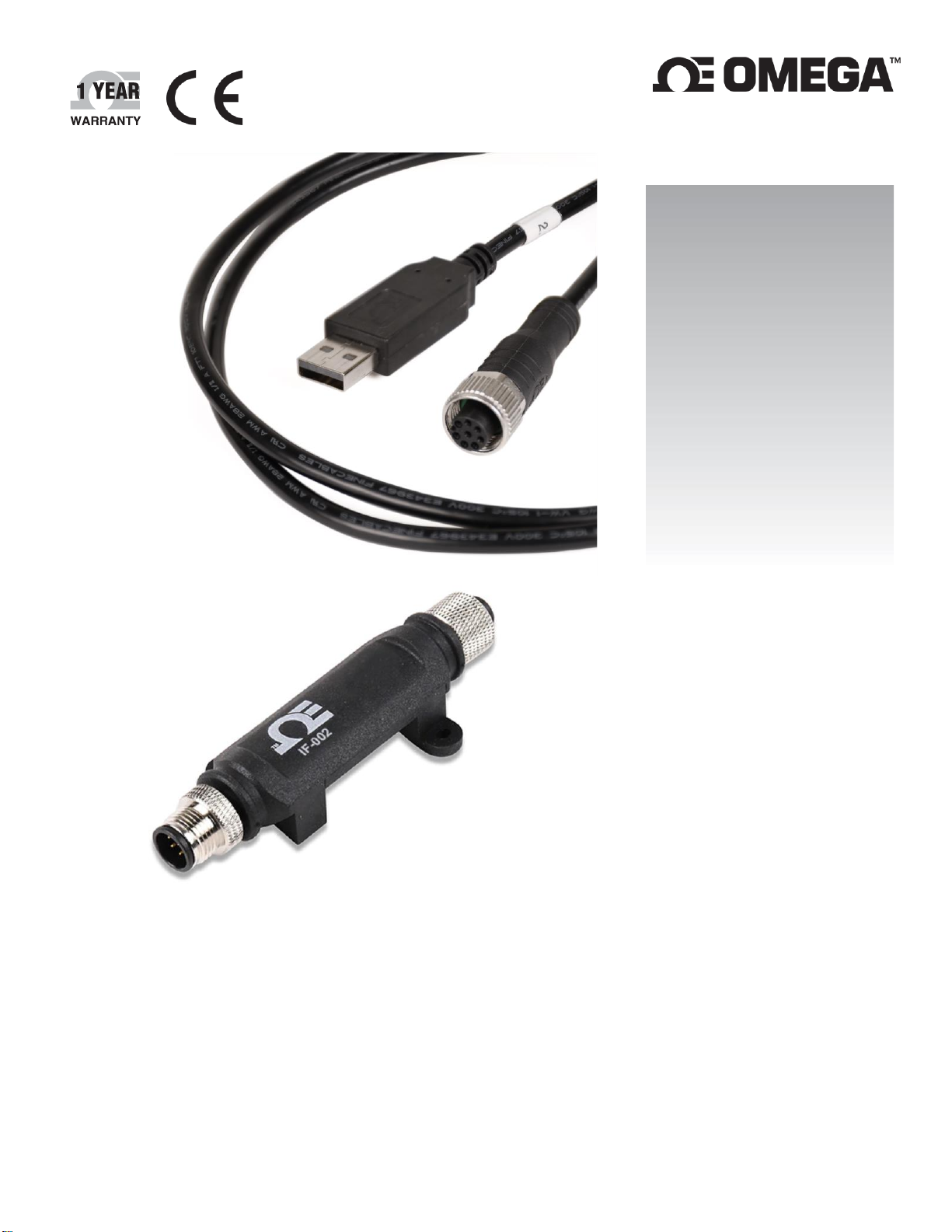
USB/Modbus Smart Interface
Page 2

The information contained in this document is believed to be correct, but OMEGA accepts no liability for any errors it contains and reserves the right to
alter specifications without notice.
omega.com [email protected]
Omega Engineering, Inc:
800 Connecticut Ave. Suite 5N01, Norwalk, CT 06854, USA
Toll-Free: 1-800-826-6342 (USA & Canada only)
Customer Service: 1-800-622-2378 (USA & Canada only)
Engineering Service: 1-800-872-9436 (USA & Canada only)
Tel: (203) 359-1660
e-mail: [email protected]
Fax: (203) 359-7700
Omega Engineering,
Limited:
1 Omega Drive, Northbank,
Irlam Manchester M44 5BD
United Kingdom
Omega Engineering,
GmbH:
Daimlerstrasse 26 75392
Deckenpfronn Germany
2 | M 5 7 57
Page 3

Table of Contents
Table of Contents ............................................................................................................................................. 3
1 Notes, Cautions, and Warnings .................................................................................................................. 4
2 Omega Link Smart Interface Overview ....................................................................................................... 5
2.1 IF-001...............................................................................................................................................................5
2.2 IF-002...............................................................................................................................................................5
3 Smart Interface Pin Layouts ....................................................................................................................... 6
3.1 IF-001: Smart Probe to USB ...............................................................................................................................6
3.2 IF-002: Smart Probe to Modbus RTU .................................................................................................................7
4 IF-001 and IF-002 Serial Communication ..................................................................................................... 8
4.1 Serial Packet Format.........................................................................................................................................8
4.2 Modbus Register Mapping ................................................................................................................................9
4.3 Configuration Registers ....................................................................................................................................9
4.3.1 I2C Status............................................................................................................................................................. 10
4.3.2 System Control Register ...................................................................................................................................... 10
4.4 Serial Configuration (IF-002) ........................................................................................................................... 11
4.4.1 Configuration Update.......................................................................................................................................... 11
4.4.2 Serial Configuration Recovery ............................................................................................................................. 12
5 Command Line Interface .......................................................................................................................... 13
5.1 Help Command .............................................................................................................................................. 13
5.1.1 Alternate Address {Add}...................................................................................................................................... 13
5.1.2 Numeric Formats ................................................................................................................................................. 14
5.1.3 Command Repetition @, #, / .............................................................................................................................. 14
5.2 Read Command .............................................................................................................................................. 15
5.3 View Command .............................................................................................................................................. 16
5.4 Trigger Command ........................................................................................................................................... 17
5.5 Serial Command ............................................................................................................................................. 17
5.6 Configure Command ....................................................................................................................................... 18
5.6.1 Configure Device ................................................................................................................................................. 19
5.6.2 Configure Sensors and Outputs .......................................................................................................................... 20
5.7 Option Command ........................................................................................................................................... 22
5.7.1 Verbose Mode ..................................................................................................................................................... 23
5.8 Hex / hex / Decimal Option ............................................................................................................................ 23
5.9 INTR Processing .............................................................................................................................................. 24
5.9.1 Ignore INTR .......................................................................................................................................................... 24
5.9.2 Process INTR ........................................................................................................................................................ 24
5.9.3 I2C Address .......................................................................................................................................................... 25
5.9.4 Bus Speed ............................................................................................................................................................ 25
5.9.5 Modbus Address ................................................................................................................................................. 25
6 Appendix A: Smart Sensor Register Summary ........................................................................................... 26
7 Appendix B: Specifications ....................................................................................................................... 28
1 8. Appendix C: Texas Instrument License Statement ................................................................................. 28
8 Appendix C: Texas Instrument License Statement ..................................................................................... 29
3 | M 5 7 57
Page 4
1 Notes, Cautions, and Warnings
If the equipment is used in a manner not specified in this manual, the protection by the equipment may be impaired.
Do not operate the equipment in flammable or explosive environments.
It is important to read and follow all precautions and instructions in this manual before operating or commissioning
this device as it contains important information relating to safety and EMC. Failure to follow all the safety precautions
may result in injury and/or damage to the equipment.
The following labels identify information that is especially important to note:
Note: Provides information that is important to successfully set up and use the Omega Link device.
Caution or Warning: Informs about the risk of electrical shock.
Caution, Warning, or Important: Informs of circumstances that can affect the functionality of the instruments
and must refer to accompanying documents.
4 | M 5 7 57
Page 5
2 Omega Link Smart Interface Overview
Color
Status
Off
No Activity (no VBus present), waiting for next command
YELLOW
Waiting for USB enumeration, Pending Bootstrap mode
RED – 1-second
flash rate
A short condition has been detected on the sensor power circuitry. Disconnect
the device.
RED – ¼ second
flash
A message to the device was not acknowledged.
GREEN
After power-up and USB enumeration, the GREEN LED remains on until the
first transaction with the smart sensor device
GREEN Flash
The GREEN LED is turned on at the beginning of each transaction with the
Smart Sensor and turned off at the end.
The Omega Link IF-001 and IF-002 smart interfaces provide an easy way to configure, integrate, and monitor your
Omega Link Smart Probes. The IF-001 and IF-002 are both fully compatible with SYNC configuration software, the
Omega Link Cloud, the Omega Link family of hardware Gateways, and Omega Enterprise Gateway software. Omega Link
Smart Interfaces provide both a simple command line interface, for quick configuration and monitoring, and Modbus
RTU support, for integration with industrial networks. The command line interface allows interactive visualization of the
connected Omega Link Smart Probe through accessible text strings using any terminal emulator.
The M12 8-pin female connector provides 3.3 VDC power for external Omega Link Smart Probes with an integrated
power monitor to protect against short circuits.
Operating Requirements: Windows OS 10 and above
The following LED status indicator table provides descriptions of the different Smart Interface behaviors.
2.1 IF-001
The IF-001 provides an easy way to configure and monitor Omega Link Smart Probes using SYNC or other
configuration tools. The IF-001 is a USB CDC / VCP device (serial interface), allowing it to connect to computers
that do not have a native serial port. The USB 2.0 compliant device is compatible with Windows.
2.2 IF-002
The IF-002 allows Omega Link Smart Probes to connect to existing RS485 Modbus RTU serial networks. An M12 5pin male connector provides a standard RS485 serial interface. The IF-002 can run off a wide range of power, from
5 to 36 VDC, allowing broad compatibility while providing regulated power to Smart Probes.
5 | M 5 7 57
Page 6
3 Smart Interface Pin Layouts
Name
Function
Pin 1
N/A
No Connection
Pin 2
INTR
Interrupt Signal
Pin 3
SCL
SCL Signal
Pin 4
SDA
SDA Signal
Pin 5
Shield
Shield Ground
Pin 6
N/A
No Connection
Pin 7
GND
Power Return
Pin 8
VCC
Nominal 3.3 VDC
to Smart Probe
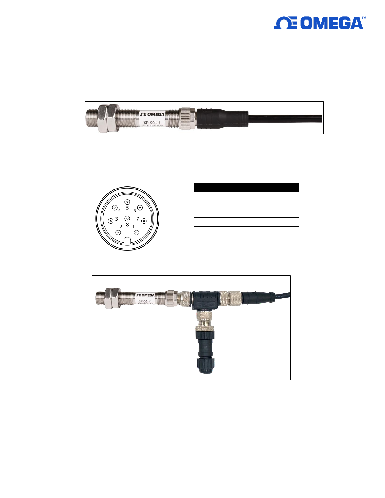
Figure 2: IF-001 front view
of M12 8-Pin Connector
3.1 IF-001: Smart Probe to USB
The IF-001 can connect direct to the Omega Link Smart Probe through an M12 8-pin female connector as shown in
the example below. The connector supports the required I2C + INTR signal lines and the Smart Probe power
signals. The shield connection is coupled to the Serial Connector.
Figure 1:Example SP-001 connected to an IF-001
The Smart Probe Discrete I/O signals are not internally connected. An M12.8-S-M-FM and M12.8-T-SPLIT are
required to access the Discrete I/O Use the wiring diagram below to connect your Smart Probe and Discrete I/O
accessories to the IF-001 cable.
Figure 3: Example SP-001 connected to an M12.8-T-SPLIT, M12.8-S-M-FM, and IF-001
6 | M 5 7 57
Page 7
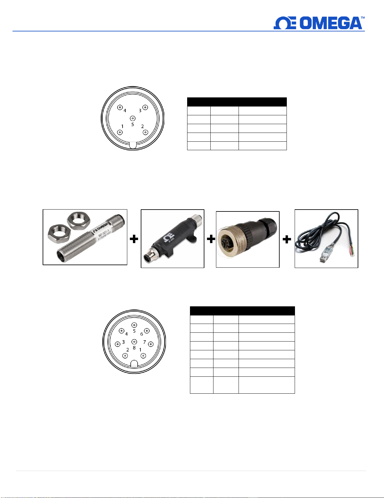
3.2 IF-002: Smart Probe to Modbus RTU
Name
Function
Pin 1
VDD
5-36V
DC
Pin 2
A’
RS485 Data +
Pin 3
GND
Ground
Pin 4
B’
RS485 Data -
Pin 5
Shield
Shield Ground
Name
Function
Pin 1
N/A
No Connection
Pin 2
INTR
Interrupt Signal
Pin 3
SCL
SCL Signal
Pin 4
SDA
SDA Signal
Pin 5
Shield
Shield Ground
Pin 6
N/A
No Connection
Pin 7
GND
Power Return
Pin 8
VCC
Nominal 3.3 VDC
to Smart Probe
Figure 4: IF-002 front view
of M12 5-Pin Connector
Figure 6: IF-002 unit
Figure 5: SP-001
Figure 7: M12.5-S-F-FM
Figure 8: USB to RS485
Cable
Figure 9: IF-002 front view
of M12 8-pin connector
The IF-002 is used to connect to an existing Serial Modbus network through its M12 5-pin connector and directly to
M12 Smart Probes through its M12 8-pin connector. The serial 5-pin connector provides the RS485 differential pair
signal (A’, B’), power input, and a shield signal. The device will accept external power in the range of 5 – 36 VDC
with reverse polarity and overcurrent protection up to 300 mA.
Additionally, a 5-pin M12.5-S-F-FM connector and a third-party USB to RS485 Serial Converter Cable are required
to establish a connection from the IF-002 and the USB COM Port of your PC or Modbus device. Refer to the wiring
diagram provided with your USB to RS485 to successfully connect the IF-002 wire leads of the USB to RS485 cable.
An M12.8-S-F-FM and M12.8-T-SPLIT can be attached to the Smart Probe prior to connecting to the IF-002 to
access the discrete I/O using the following wiring diagram.
7 | M 5 7 57
Page 8
4 IF-001 and IF-002 Serial Communication
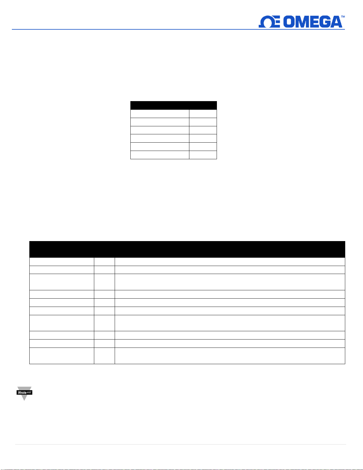
Default Serial Configuration
Modus Address
1
Address Range
0
Baudrate
115200
Parity
Even
Stopbits
1
Databits
8
Start of Frame
Character
Hex
Interpretation
#
0x23
Command Line Interface comment line (ignored)
:
0x3a
Start of Frame for Modbus ASCII frame
?
0x3f
Command Line Interface ‘Help’ command – display command / current state
summary
C
0x43
Command Line Interface ‘Configure’ command – configure Smart Probe device
O
0x4F
Command Line Interface ‘Options’ command – configuration options
R
0x52
Command Line Interface ‘Read’ command – read any Smart Probe register
T
0x54
Command Line Interface ‘Trigger’ command – trigger an event on Smart Probe
device
V
0x56
Command Line Interface ‘View’ command – view Smart Probe data and status
W
0x57
Command Line Interface ‘Write’ command – Write any Smart Probe register
Any other character
Any
other
Indicates register address for a Modbus RTU frame
The serial communication parameters may be configured over the serial channel or SYNC configuration software. The
factory default configuration conforms to the required Modbus RTU standard.
The IF-001 is a virtual COM port and will accept any serial port baud rate.
Refer to the table below for the default serial configuration of the IF-002:
4.1 Serial Packet Format
Communications to the IF-001 and IF-002 are based on serial data frames. For serial terminal sessions, the
“transaction” ends on the receipt of a CR (0x0d) character. For Modbus RTU transactions, the entire transaction
must adhere to the Modbus serial RTU time specifications.
The IF-002 uses the first byte of the transaction (the start-of-frame character) to determine the type of
transaction. For the Command Line Interface, the first character denotes the operation to be performed as
indicated in the following table:
Any other byte value appearing at the start of the frame is interpreted as a Modbus RTU Modbus device address.
Note: This requires excluding several Modbus addresses in the RTU mode, but in most cases this will have
no impact.
8 | M 5 7 57
Page 9
4.2 Modbus Register Mapping
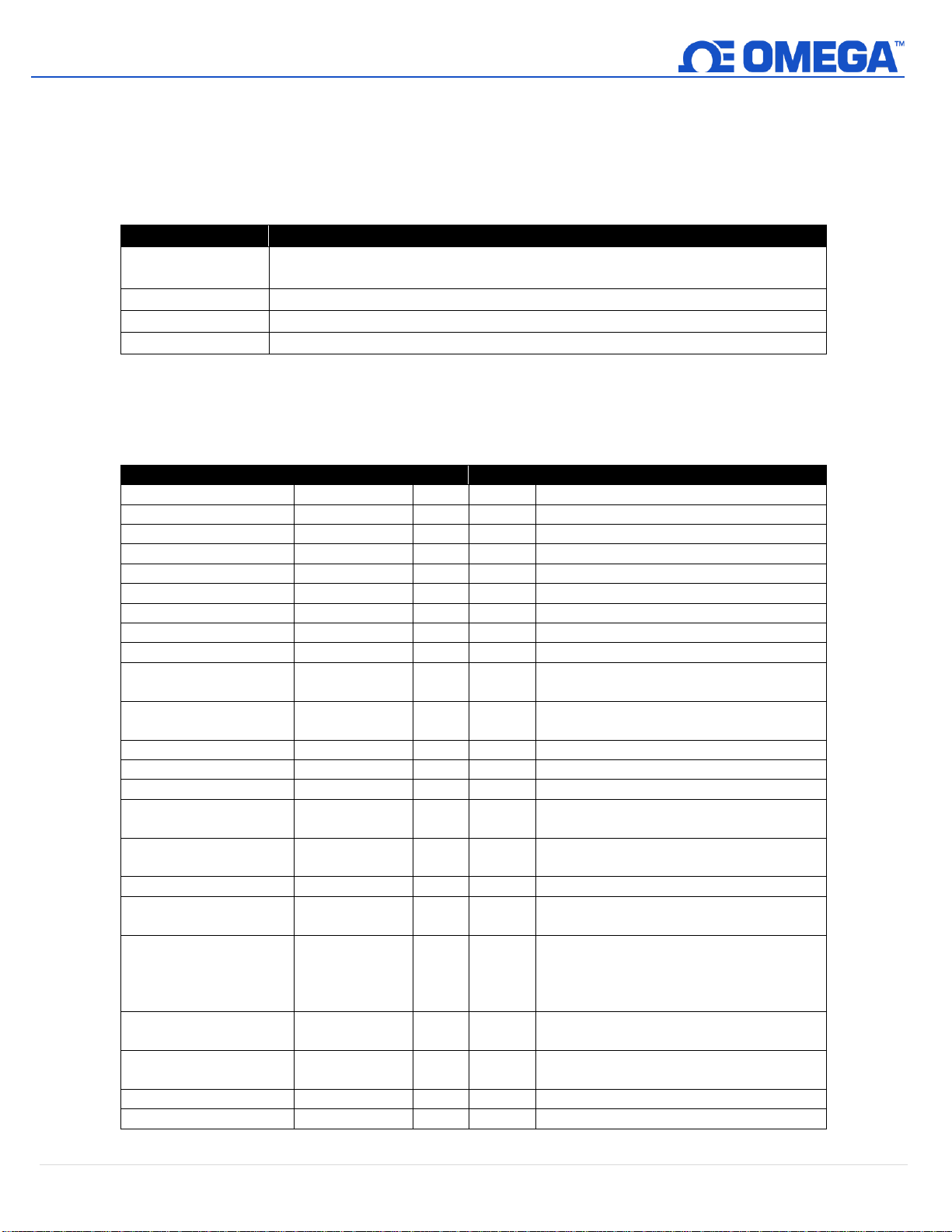
Modbus Register
Usage
0x0000 – 0xebff
Register address 0x0000 – 0xebff and addresses 0xf800 – 0xffff are not
recognized and will result in an INVALID ADDRESS response
0xec00 – 0xefff
Registers 0xec00 – 0xefff are reserved for configuration of the IF-001 / IF-002
0xf000 – 0xf7ff
Registers 0xf000 – 0xf7ff are mapped to the external I2C device(s)
0xf800 – 0xf800
Invalid Address
MB Register
Type
Access
Description
Reserved
0xec00 – 0xefcf
u16
--
Reserved, return Invalid Address
I2C_Read Errors
0xefd0
u32
R
Number of Read errors
I2C_Write_Errors
0xefd2
u32
R
Number of Write errors
I2C_Read Retries
0xefd4
u32
R
Number of Read Retries
I2C_Write_Retries
0xefd6
u32
R
Number of Write Retries
I2C_Indirect_Retries
0xefd8
u32
R
Number of Read Retries
I2C_Read_Request
0xefda
u32
R
Number of read requests
I2C_Write_Request
0xefdc
u32
R
Number of write requests
Reserved
0xecda – 0xefe7
--
--
Reserved, return Invalid Address
DEVICE_ID
0xefe8-0xefeb
u8[8]
RW*
Read only, but used as part of Bootload
access mechanism
FW_VERSION
0xefec-0xefed
u32
RW*
Read only, used as part of Bootload access
mechanism. Formatted as MM.mm.bb.cc
HW_VERSION
0xefee-0xefef
u32
R
Formatted as MM.mm.bb.cc
DEVICE_TYPE
0xeff0
u16
R
0xff01 == IF-002
SYSTEM CONTROL
0xeff1
u16
R/W
<see below>
I2C_BASE_ADDRESS
0xeff2
u16
R/W
Defaults to 0x68. Sets the base address of
I2C device(s).
I2C_SPEED
0xeff3
u16
R/W
I2C bus speed in kHz, ie 40 == 40
kbit/second
SERIAL_CONFIG
0xeff4
u16
R/W
See Serial Configuration Word
MODBUS_ADDRESS
0xeff5
u16
R/W
Defaults to 1. Sets the base address for
Modbus transactions. Limited to 1 .. 247.
ADDRESS_RANGE
0xeff6
u16
R/W
Default to 0, limited to 0..7. Sets number of
consecutive Modbus addresses accepted.
Each Consecutive Modbus address maps to
consecutive I2C device addresses.
MANUFACTURED_DATE
0xeff8
u16
R
Bit packed value with format
YYYYY.MM.DD
USER_HOURS
0xeff9
u16
R/W
User settable counter, increments every
3600 seconds
OPERATING_TIME
0xeffa
u32
R
Total number of seconds of operation
GATEWAY_CONTROL
0xefff
u16
R
Reserved
The IF-001 and IF-002 accept RS485 Modbus RTU packets. The IF-001 / IF-002 maps the Modbus register addresses
to internal configuration registers and to external I2C registers.
Modbus Register = ((Smart Probe 12C Register) / 2) + 0xf000
4.3 Configuration Registers
The configuration registers are stored in non-volatile memory. Changes to the serial configuration and Modbus
address take effect after the Modbus Transaction.
9 | M 5 7 57
Page 10
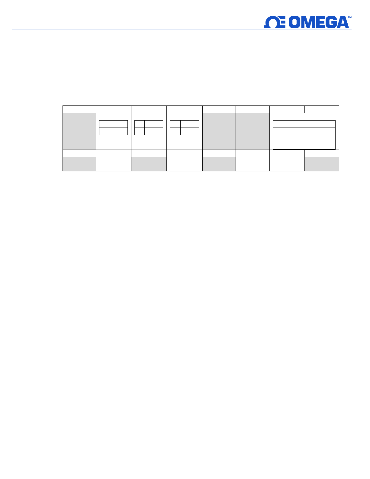
4.3.1 I2C Status
7 6 5 4 3 2 1
0
CLI
HEX
VERBOSE
INTR MODE
0
ON 1 OFF
0
ON 1 OFF
0
ON 1 OFF
0
Ignore
1
Process INTR
2
Send Notify
3
15
14
13
12
11
10 9 8
Reserved
Reset
Stats
Device
Reset
Factory
Reset
Modbus registers 0xefd0 - 0xefd9 provide access to statistics indicating the number of I2C errors and retries.
The Retry counts indicate the number of transactions that resulted in an NAK. When an NAK is detected, the
IF-001 / IF-002 will automatically generate up to 3 retries. If an NAK is detected on the 3rd attempt the
transaction is dropped, an error is reported and the Read or Write Error count is incremented. The Indirect
Retry count is incremented if an NAK is generated when writing the Indirect register (0x0030).
4.3.2 System Control Register
4.3.2.1 INTR Mode
The INTR Mode determines how the Smart Probe INTR signal is handled. If it is set to PROCESS, the
Command Line Interface activity is processed. If it is set to Notify, the device will send a NOTIFY
command through the Command Line Interface. For Modbus applications, the INTR Mode should
be set to IGNORE.
4.3.2.2 Verbose
The Verbose mode offers expanded information when in the Command Line Interface mode.
4.3.2.3 Hex
The Hex mode causes the data to be displayed as HEX values in the Command Line Interface mode.
4.3.2.4 Device Reset
Writing a 1 to the device reset bit will force the device to re-initialize using the current
configuration information.
4.3.2.5 Factory Reset
Writing a 1 to the Factory Reset bit will force a factory reset and all configuration parameters will
be returned to the initial factory default values.
4.3.2.6 Reset Stats
Writing a 1 to the reset stats bit will force the I2C Statistic counters to be reset to 0.
10 | M 5 7 57
Page 11
4.4 Serial Configuration (IF-002)
7
6 5 4
3 2 1
0
Reserved
Data Width
Stop Bits
Parity
Baud Rate
0
7 Stop Bits
1
8 Data Bits
0
1 Stop
1
2 Stop
0
No Parity
1
Mark Parity
2
Odd Parity
3
Even Parity
0
9600
1
19,200
2
38,400
3
115,200
15
14
13
12
11
10 9 8
Reserved
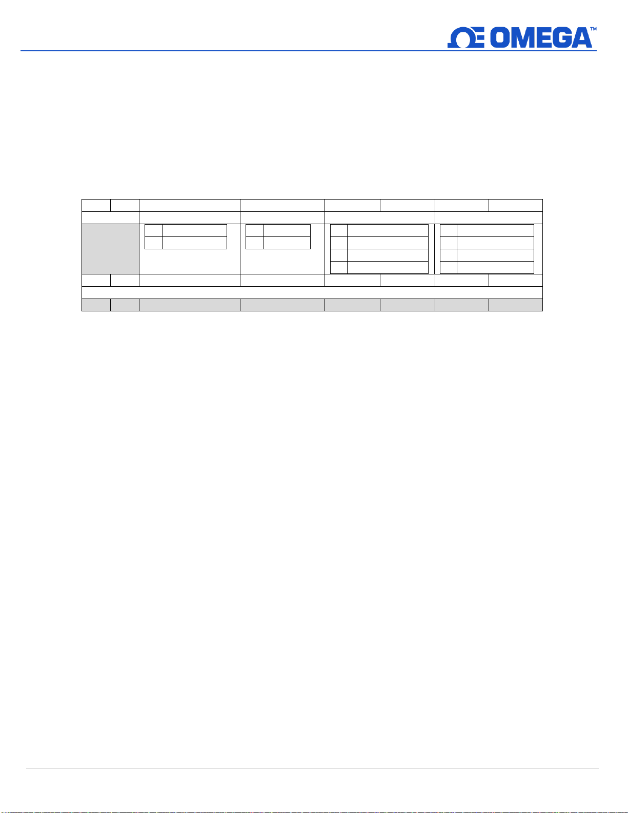
All serial line configuration is done through the serial channel using Modbus or Command Line Interface
commands and the configuration information is retained in non-volatile memory. When accessed via Modbus, the
serial configuration parameters are accessed at a Modbus register address which is outside of the range mapped
to the Smart Sensor registers. When altering the communications parameters, any changes occur after the
acknowledgment of the Modbus command.
The device serial configuration word is located at Modbus register address 0xeff4.
4.4.1 Configuration Update
The IF-002 Modbus commands accept changes to the serial configuration (Baudrate, Parity, Stop Bits, Data
Bits) but does not apply them until the next power cycle or a Device Reset trigger has been received. This
allows all serial configuration parameters to be set using Modbus commands without having to change the
host settings as each configuration setting change is made. All other configuration changes are applied
immediately.
The sequence to change the communication parameters over the Modbus connection is:
Step 1: Change one or more parameters – each change is acknowledged using the current Serial settings
Step 2: Issue a Write command to the IF-002 System Control Register with the Device Reset bit set.
The command will be acknowledged using the current settings and then the serial channel will be
reconfigured to reflect the new settings.
The Command Line Interface includes a Serial command that allows you to set the serial channel. These
take immediate effect. In general, the terminal emulator must be reconfigured after the command to
match the new configuration.
11 | M 5 7 57
Page 12
4.4.2 Serial Configuration Recovery
Name
Function
Pin 1
N/A
No Connection
Pin 2
INTR
Interrupt Signal
Pin 3
SCL
SCL Signal
Pin 4
SDA
SDA Signal
Pin 5
Shield
Shield Ground
Pin 6
N/A
No Connection
Pin 7
GND
Power Return
Pin 8
VCC
Nominal 3.3 VDC
to Smart Probe
Name
Function
Pin 1
VDD
5-36V
DC
Pin 2
A’
RS485 Data +
Pin 3
GND
Ground
Pin 4
B’
RS485 Data -
Pin 5
Shield
Shield Ground
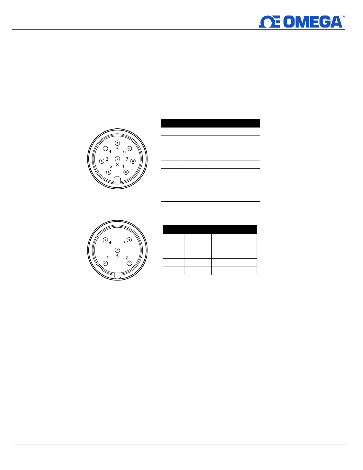
The IF-002 serial configuration may be reset to the factory default values by momentarily connecting the
SCL (M12 8-Pin Pin 3) and SDA (M12 8-Pin Pin 4) signal lines together and cycling power. To reset the IF-002
to its factory default settings, follow these steps:
Step 1: Disconnect power from the IF-002 by disconnecting it from your Modbus Network.
Step 2: Unplug any smart probe connected to your IF-002.
Step 3: Short pins 3 and 4 on the 8-Pin connector on the IF-002.
Step 4: Apply power to the IF-002 for 3 seconds from the 5-pin connector.
Step 6: Reconnect your Omega Link Smart Probe and apply power.
12 | M 5 7 57
Page 13

5 Command Line Interface
?
IF-002, Version 1.11.0.0
O(ptions) <V/v(erbose)> <H/h(ex)/D(ecimal)> <I(gnore) | P(rocess) | N(otify) INTR handling>
<A/a(ddr for I2C) =?> <S(peed) =?> <M(odbus Addr) =?> <R(ange) = ?>
R(ead) <@><#n></d><{Add}> Reg [Len <format> ...]
W(rite) <@><#n></d><{Add}> Reg [data <format>...]
V(iew) <@><#n></d><{Add}> <I(nfo) | D(ata) | L(og) | N(ext)
T(rigger) <@><#n></d><{Add}> <R(eset) | F(actory reset) | P(ower reset) | C(lear log) | S(ample) | L(og)
S(erial) <B(audrate) = 9600 | 19200 | 38400 | 115200> <P(arity) = E(ven) | O(dd) | M(ark) | N(one)>
<S(top) = 1 | 2> <D(ata) = 7 | 8> <R(eset)>
C(onfig) <@><#n></d><{Add}><R(ate) | I(nterrupt) | D(evice) | S(ensor nn) | O(utput nn)
@ - Continuous/no delay, #n - number cycles, /d - delay time, <..> - are optional
formats: I/i(nteger), L/l(ong), F/f(loat).precision, S/s(string)
Verbose, Hex, internal INTR use, I2C Addr: 0x68 @ 50 kbp, Modbus Addr: 0x01, Modbus Range: 0x00
Note: The following Command Line Interface section can be applied to both the IF-001 and the IF-002.
The command line interpreter allows human-readable commands to be sent to the smart sensor device through a
terminal emulator which are widely available and may be easily installed on a PC or Linux systems. The COM channel
enumerated by the device must be selected and must be configured to match the serial configuration parameters.
(Refer to Appendix A).
5.1 Help Command
The Help command uses the ‘?’ character and will display a brief summary of the available commands and options.
It is useful to determine if the IF-001 / IF-002 is successfully communicating and does not require a smart probe
device to be connected.
5.1.1 Alternate Address {Add}
The I2C address used to access the Smart Sensor device defaults to 0x68, unless overwritten by the Options
command. The address may be further overwritten in each command by enclosing the address in { }
bracket.
13 | M 5 7 57
Page 14
5.1.2 Numeric Formats
Data Type
Suffix
Example (Assume Hex Option Selected)
Byte
<none, default>
R 0x68 -> display single byte value
16-bit integers
i
R 0x68 20 2 i -> result displayed as 0x1234
32-bit integers
l (lower case ‘L’)
R 0x68 20 2 l -> result displayed as 0x12345678
Floats
f.n (n == precision)
R 0x68 0x3c 4 f.3 → result displayed as 12.345, precision is optional
and defaults to 1 digit.
Strings
S/s
R 0xe0 s → result displays the user-defined device name located at
0xe0
W 0xe0 “My Name” → will write a new device name to the string.
Be cautious not to exceed the maximum string lengths.
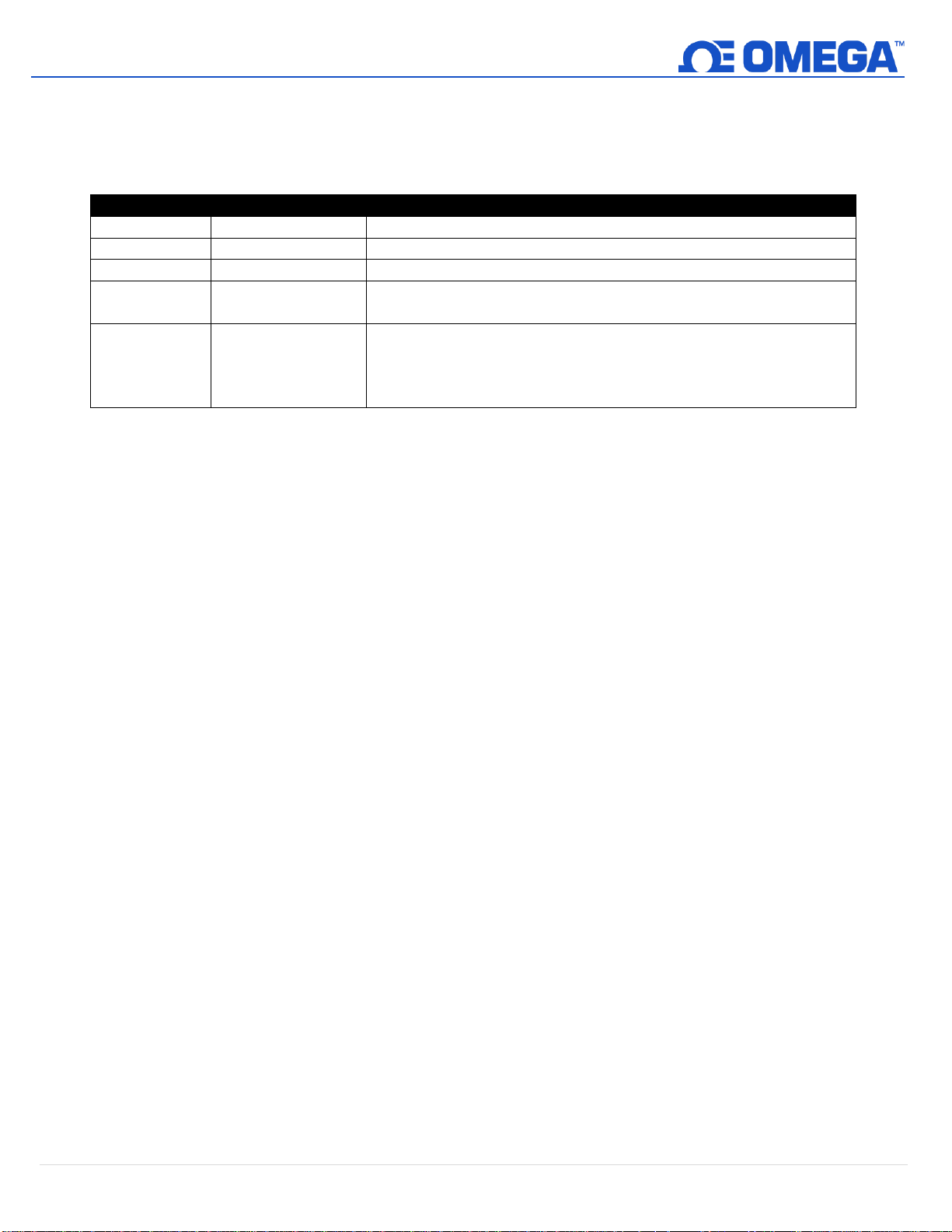
Data may be entered or displayed as hexadecimal, decimal or float values. The standard output shows data
in decimal or hex format depending on the Verbose H/h/D mode setting, which may be overwritten using
formatting characters. The following formatting characters are accepted:
5.1.2.1 Invalid Commands
Since the first character of the serial record is used to determine the Command Line Interface
command and all other characters are treated as Modbus Start of Frame (‘:’) or address values, no
interpretation is made of characters other than those shown in the Help summary and no error
reporting will be generated.
5.1.3 Command Repetition @, #, /
The Read, Write, View, Configure and Trigger commands may be set up to repeat a specific number of times
with an optional repetition rate. Repeated commands are terminated if an error occurs or any keyboard
entry is made.
• The ‘@’ symbol causes the command to be repeated indefinitely, at the fastest possible rate. If the @
symbol is specified, the # and / may not be used.
• The ‘#’ symbol, followed by a numeric value, causes the command to be repeated the specified
number of times.
• The ‘/’ symbol, followed by a numeric value, allows specifying a delay in seconds between each
command repetition when using the ‘#’ option.
If no repetition information is provided the command will be executed once.
14 | M 5 7 57
Page 15

5.2 Read Command
// Location 0x3c represents the sensor readings, stored as floating point values.
// Read a single byte from the start of the sensor values (default count is 1, type byte)
R 0x3c
[Dev: 0x68 Reg: 0x3c Cnt: 0x01 -> 0x41 ]
// Read 2 bytes (the format defaults to BYTE)
R 0x3c 2
[Dev: 0x68 Reg: 0x3c Cnt: 0x02 -> 0x41, 0xb7 ]
// Read 3 ‘long ‘ (4 byte) values, representing 12 (0x0c) bytes
R 0x3c 3l
[Dev: 0x68 Reg: 0x3c Cnt: 0x0c -> 0x41b73333, 0x42483d71, 0x447605c3 ]
// Read 3 ‘float’ ( 4 byte ) values, representing 12 ( 0x0c ) bytes, default precision is 2
R 0x3c 3f
[Dev: 0x68 Reg: 0x3c Cnt: 0x0c -> 22.8, 50.1, 984.0 ]
// Read 3 float values and display with 4 digit precision
R 0x3c 3f.4
[Dev: 0x68 Reg: 0x3c Cnt: 0x0c -> 22.8899, 50.1899, 984.1099 ]
O v d
verbose, Decimal mode, Ignore INTR, I2C Addr: 0x68 @ 50 kbp, Modbus Addr: 0x01
Read 0x38 1l 4f.2
0000367195 23.22, 28.27, 1013.40, 0.00
The Read command accepts the repetition information, the starting register number, the number of elements to
be read and the format of the data. The starting register location must be provided while all other fields are
optional. If the number of elements is omitted, it is assumed to be one. If the data format is omitted, it is assumed
to be BYTES. There may be multiple elements and related format information contained within a read. Commas or
spaces may be used to separate the individual values.
R(ead) <repetition options> register [<number> <format <.precision>> …]
The simplest form is R 0x????, where 0x???? represents a value between 0x0000 and 0x0fff. The command will
return a single byte from the specified location. A more complex example would be Read 0x38 1l 4f.2 to read the
current time, and the 4 sensor readings. The Time information is stored in register 0x38 as a 32-bit long value and
is then immediately followed by the four sensor results stored as floating-point values at locations 0x003c ..
0x004b.
15 | M 5 7 57
Page 16
5.3 View Command
Information Group
Attributes (registers)
Usage
I(nformation)
Device Name (0xe0),
Device ID (0x00)
Number of Sensors (0x00)
Number of Outputs (0x00)
Provides summary of the device status and health used
to take the measurements.
D(ata)
Current Time,
Sensor Readings,
Sensor Units
Provides summary of current time, reading values and
units of measure.
L(og)
Extract Start, Extract End,
Number Records
Provides information on information contained in Log
file
N(ext)
Extract Time
Extract Data
Extracts and displays the next log file record
View Information
Device: Device Name, ID: 00000001
Type: BTH-SP, Version: 1.25.4.0
Manufactured: 2017/08/25, Operating Hours: 11-13:33:48
Calibrated: 2017/08/25, Calibration Hours: 11-13:33:48
Oper Volt: 3.3 Vdc,Oper Temp: 21 oC, Fault Code: 0
Sensors: 3, Outputs: 2
View L
Start Time: 11-13:06:41, End Time: 11-13:33:59, Records Available: 820
V Data
11-13:34:03 21.0 .C 28.0 %RH 1017.0 mbar
V N
11-13:34:01 21.0 .C 28.0 %RH 1017.0 mbar
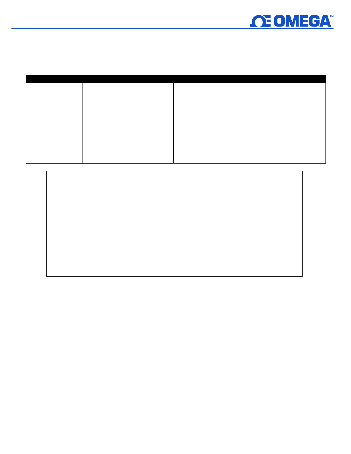
The View command accepts an option that specifies what is to be displayed. If no option is provided the command
assumes the View Information option.
V(iew) <repetition options> <I(nformation) | (D(ata) | L(og) | N(ext)>
16 | M 5 7 57
Page 17
5.4 Trigger Command
Action
Trigger Register, Value
Usage
R(eset)
Trigger Register =
Trigger Value 0x0004
Reset device forcing re-enumeration of sensor mix
F(actory reset)
Trigger Register =
Trigger Value 0x0005
Forces a factory reset which clears all user set up and
logged information
P(ower reset)
Trigger Register =
Trigger Value 0x0006
Performs a user reset that is treated as a power on
reset which includes logging the event in the event log.
C(lear)
Trigger Register =
Trigger Value 0x0003
Clears the event log
S(ample)
Trigger Register =
Trigger Value 0x0100
Forces a sampling of the sensor data. The data is not
written to the event log. The display will show the
current values.
L(og)
Trigger Register (0x26),
Trigger Value 0x0300
Forces a sampling of the sensor data and the
information is saved to the event log. The display will
show the current values.
Characteristic
Options
Usage
Baudrate)
9600, 19200, 38400, 115200
Serial Baudrate = 38400
Parity
Even, Odd, Mark, None
S P=None
Stop
1, 2
S S=2
Data
7, 8
Serial Databits = 8
Reset
--
Resets serial configuration to 115200, Even,
8, 1
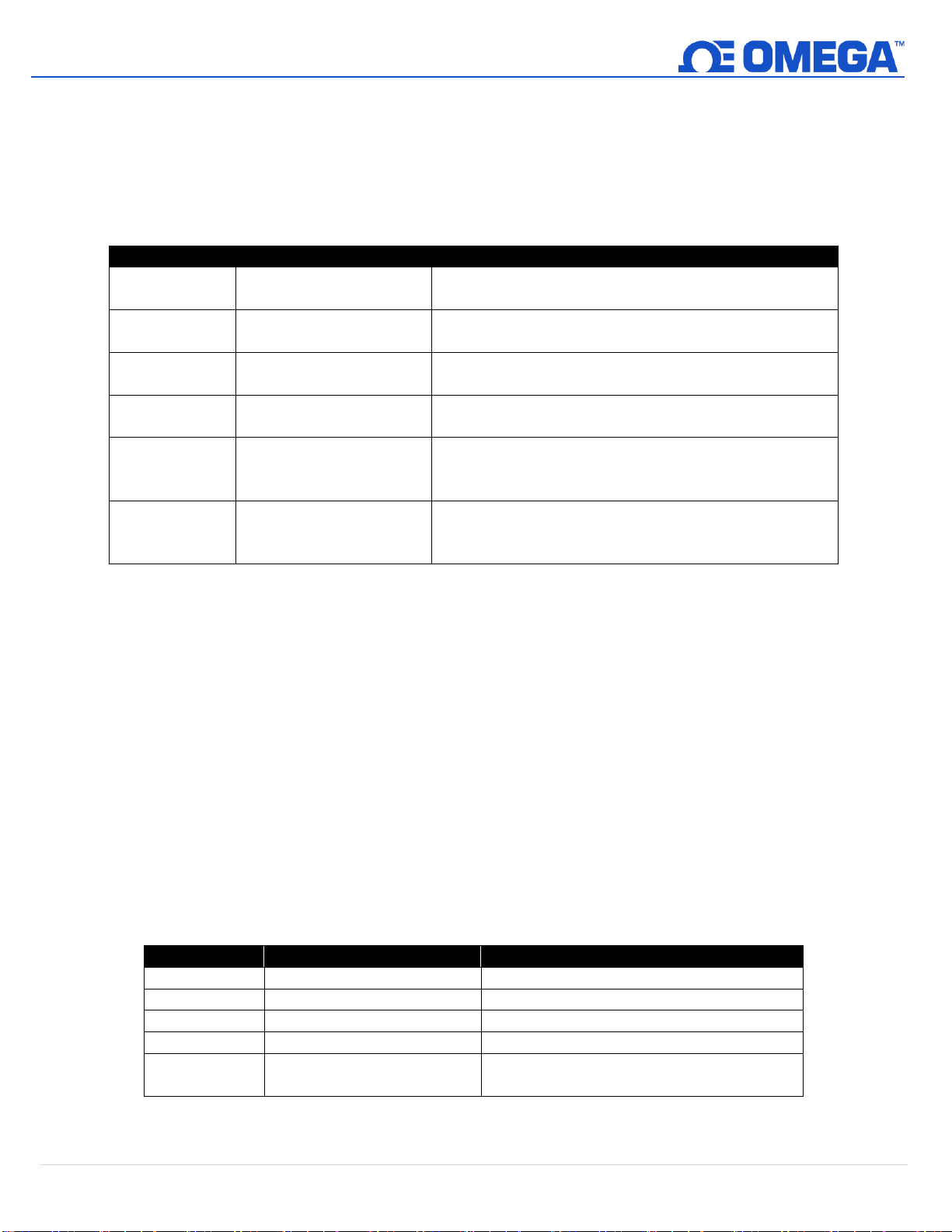
The Trigger command allows users to initiate an action on the smart sensor. The Trigger commands makes use of
the options provided by the Trigger register at register location 0x26. If no option is provided, a Trigger Log
sequence will be performed, forcing a reading to be taken and saved to the event memory.
T(rigger) <repletion options> <R(eset) | F(actory reset) | P(ower reset) | C(lear) | S(ample) | L(og)>
5.5 Serial Command
The Serial command allows setting specific operating characteristics of the Serial interface. If no option is provided
the current settings for the selected characteristics are provided.
S(erial) <B(audrate) = 9600 | 19200 | 38400 | 115200> <P(arity) = E(ven) | O(dd) | M(ark) | N(one)>
<S(top) = 0 | 1> <D(ata) = 7 | 8> <R(eset)>
S
Baudrate = 115200, Parity = Even, Data = 8, Stop = 1
Multiple options may be set on the same command line in any order. The updated configuration will be shown
using the current serial configuration and then all changes are applied at once.
Serial BR=38400, Stop = 1, Data=7 Parity = Odd
Baudrate = 38400, Parity = Odd, Data = 7, Stop = 1
<changes are applied, terminal configuration must be changed to match new configuration>
17 | M 5 7 57
Page 18

5.6 Configure Command
Characteristic
Attributes (registers)
Usage
R(ate)
Event 1 Time Base
C R
Displays current Rate
C R = xx
Sets the Event 1 sample time, which is the default timer,
used to trigger reading and logging activity.
D(evice)
IO_DEVICE_NAME
IO_LIST_SELECT
C D
Displays the I/O mix available on the device with an
indication of how to select different configurations.
C D = nn
Allows selecting device configuration from available
options shown in the C D command.
S(ensors)
C S
Displays the list of all available sensors on the device and
available configuration options.
C S n
Displays the configuration options available on sensor ‘n’.
C S n = x
Allows selecting a sensor configuration option from
available options shown in the C S n command
O(utputs)
0x??
C O
Displays the list of all available outputs on the device and
available configuration options.
C O n
Displays the configuration options available on output ‘n’.
C O n = x
Allows selecting a output configuration option from
available options shown in the C O n command
The Configure command sets specific operating characteristics of the device. If an option is not provided, the
current settings for the selected characteristic are provided. If no characteristic is provided, a summary of the
Configure command is provided.
C(onfig) <repetition options> <R(ate) | D(evice) | S(ensors) | O(utputs)> < option >
18 | M 5 7 57
Page 19

5.6.1 Configure Device
C D
SP-003-1 Options
T / OUT (option: 0)
H / OUT (option: 1)
T,H / OUT (option: 2)
B / OUT (option: 3)
T,B / OUT (option: 4)
H,B / OUT (option: 5)
>> T,H,B / OUT (option: 6)
C D = 1
SP-003-1 Options
T / OUT (option: 0)
H / OUT (option: 1)
T,H / OUT (option: 2)
B / OUT (option: 3)
>> T,B / OUT (option: 4)
H,B / OUT (option: 5)
T,H,B / OUT (option: 6)
The Configure Device command displays a list of different device configurations as shown below. In this
example, there are 2 configurations available (0 to 1) and currently option #6 is selected.
To change the device configuration, enter C D = n, where n is one of the displayed options. The device will
be reconfigured, a ‘Reset’ will be generated to force the new input selections to be enumerated and a
revised list will be displayed.
19 | M 5 7 57
Page 20

5.6.2 Configure Sensors and Outputs
C S
Sensor Type (0) Options
DIN (option: 0)
>> RATE (option: 1)
WIDTH (option: 2)
DUTY (option: 3)
DELAY (option: 4)
CNT (option: 5)
U/D_CNT (option: 6)
PLS
NO/PU (option: 7)
>> NC/PU (option: 8)
NO/PD (option: 9)
NC/PD (option: 10)
RST
NO/PU (option: 11)
NC/PU (option: 12)
>> NO/PD (option: 13)
NC/PD (option: 14)
ENB
NO/PU (option: 15)
NC/PU (option: 16)
>> NO/PD (option: 17)
NC/PD (option: 18)
Sensor (1) Options
DIO
DIO_0 Active
Disable (option: 0)
HIGH (option: 1)
>> LOW (option: 2)
DIO_1 Active
Disable (option: 3)
HIGH (option: 4)
>> LOW (option: 5)
C S 0 = 6
Sensor Type (0) Options
DIN (option: 0)
RATE (option: 1)
WIDTH (option: 2)
DUTY (option: 3)
DELAY (option: 4)
CNT (option: 5)
>> U/D_CNT (option: 6)
PLS
NO/PU (option: 7)
NC/PU (option: 8)
NO/PD (option: 9)
NC/PD (option: 10)
RST
NO/PU (option: 11)
NC/PU (option: 12)
>> NO/PD (option: 13)
NC/PD (option: 14)
DIR
NO/PU (option: 15)
NC/PU (option: 16)
>> NO/PD (option: 17)
NC/PD (option: 18)
When configuring sensors and outputs, multiple Sensor or Output Types may be presented. If any of the
‘options’ related to the Sensor or Output Type are selected the device will be reset to ensure reenumeration of the selected type and the remaining options (CLK A, RST etc.) may change.
20 | M 5 7 57
Page 21

In addition to selectable options, sensors may also contain Sensor Parameters, whose floating-point values are maintained
V i
Device: Device_19302C0C, ID: 0x010119302c0cda4d
Type: SP-013-1, Version: 0.1.4.0
Core Version: 3.31.1.0, H/W Version: 1.0.0.0
Manufactured: 2019/07/08, Operating Hours: 0-02:00:25
Calibrated: 2019/07/08, Calibration Hours: 0-02:00:25
Oper Volt: 3.3 Vdc,Oper Temp: 25 oC, Fault Code: 0x0000
Sensors: 2, Outputs: 2, Sample Rate: 1
C D
SP-013-1 Options
DIGITAL/OUT (option: 0)
>> DIGITAL, DIN/OUT (option: 1)
C S 0
Sensor Type (0) Options
DIN (option: 0)
RATE (option: 1)
WIDTH (option: 2)
DUTY (option: 3)
DELAY (option: 4)
CNT (option: 5)
>> U/D_CNT (option: 6)
PLS
NO/PU (option: 7)
NC/PU (option: 8)
NO/PD (option: 9)
NC/PD (option: 10)
RST
NO/PU (option: 11)
NC/PU (option: 12
>> NO/PD (option: 13)
NC/PD (option: 14)
DIR
NO/PU (option: 15)
NC/PU (option: 16)
>> NO/PD (option: 17)
NC/PD (option: 18)
R 0x08c0 1 f
[Dev: 0x68 Reg: 0x8c0 Cnt: 0x04 -> NAN ]
C O 0
Output (0) Options
>> ON/OFF (option: 0)
PWM (option: 1)
Active
HIGH (option: 2)
>> LOW (option: 3)
C O 0 = 6
Output (0) Options
>> ON/OFF (option: 0)
PWM (option: 1)
Active
HIGH (option: 2)
>> LOW (option: 3)
in a fixed memory space allocated for each sensor. Sensor Parameters are displayed showing the corresponding allocated
space. The corresponding Sensor Parameter may be read or written using the Read and Write commands.
21 | M 5 7 57
Page 22
5.7 Option Command
Action
Usage
V(erbose)
Turn on Verbose mode
v(erbose)
Turn off Verbose mode
H(ex)
Data values are output in hexadecimal Upper case ie: 0x1AC7
h(ex)
Data values are output in hexadecimal Lower case ie: 0x1ac7
D(ecimal)
Data values are output in decimal format ie: 6855
I(nterrupt)
Ignore (and disable) the Smart Sensor device INTR device interrupt
P(rocess)
Process the Smart Sensor INTR device interrupt
N(otify)
Notify via notification message on interrupt occurrence
A(ddress) = nnn
Set the address to be used when accessing the smart sensor device
a(ddress)
Set the default I2C address (0x68)
S(peed) = nnn
Set the I2C bus clock speed to be used
M(odbusAddr) = nnn
Set the Modbus address to be used
Serial
Configuration Options
B(audrate)
9600 | 19200 | 38400 | 115200
P(arity)
Even | Odd | Mark | None
D(atabits)
7 | 8
S(top)
1 | 2
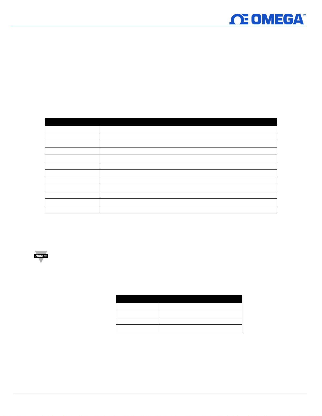
The Option command allows configuring the IF-001 / IF-002 device to use default values to simplify the user
interface by providing extended formatting options. Changes to the Options settings are retained in the internal
Flash memory.
O(ptions) <V/v(erbose)> <H/h(ex)/D(ecimal)> <I(gnore) | P(rocess) | N(otify) INTR handling>
<A/a(ddr for I2C) =?> <S(peed) =?> <M(odbus Addr) =?>
Characters shown in parenthesis (..) are optional. To Enable an option, specify the name with an upper-case
character. Multiple options may be specified in the same command line in any order. To disable the option, specify
the name with a lower-case character.
The serial port settings can be changed using the command line interface. To set the Modbus Address on your IF001 / IF-002, use the following command:
O(ptions) M(odbusAddr) = X
Note: For Modbus RTU operation the Modbus Address must be unique, Databits must equal 8, and Stopbits
must be set to 1.
Serial commands should be entered in the same line and can be separated by a comma. Use the following table
and example to set your serial configuration:
To Set the Serial Configuration options on your IF-001 / IF-002, use the following command:
S(erial) B(audrate) = X, P(arity) =X, D(atabits) = X, S(top) = X
To reset the IF-001 / IF-002 serial configuration to default, type the following command:
S R
22 | M 5 7 57
Page 23

Multiple Options may be combined into a single command line.
Option V h
Set to verbose mode, lower case hexadecimal output
Option
Verbose, Hex, Ignore INTR, I2C Addr: 0x68 @ 50 kbp, Modbus Addr: 0x01
Option Verbose
Verbose, Hex mode, i(ignore INTR), I2C Address: 0x68 @ 50 kbp, Modbus Address: 0x01
// Read current sensor readings, display as 4 floats
R 0x3c 4f
[Dev: 104 Reg: 060 Cnt: 016 -> 23.1, 50.1, 984.0, 0.0 ]
// Force failure by disconnecting device
R 0x3c 4f
[Dev: 104 Reg: 060 E_NAK (009)
O v
verbose, Decimal mode, n(INTR ignored), I2C Address: 0x68 @ 50 kbp, Modbus Address: 0x01
R 0x3c 4f
23.1, 49.8, 983.9, 0.0
R 0x3c 4f
E_NAK (009)
Example:
The response from the Option command is a summary of the current settings. Entering the O command with no
parameters returns the current settings.
5.7.1 Verbose Mode
The Verbose mode adds formatting characters to command responses. Commas are inserted between each
field and each record is enclosed in [ ] brackets.
5.8 Hex / hex / Decimal Option
The Hex / hex and Decimal option determines how numeric data is displayed if not specifically designated
as a float or string value. When entering data, a ‘0x’ indicates a hex value.
23 | M 5 7 57
Page 24
5.9 INTR Processing
Interrupt Status Bits
Enabled
Handler Action
SENSOR CHANGE
Y
Executes a ‘View Info’ command
POWER CHANGE
Y
Executes a ‘View Info’ command
HEALTH CHANGE
Y
Executes a ‘View Info’ command
EVENT 0
N
Display ‘EVENT 0 INTERRUPT’
EVENT 1
N
Display ‘EVENT 1 INTERRUPT’
DATA READY
Y
Executes a ‘View Data’ command (precede with ‘!’)
FUNCTION BLOCK
N
Display ‘FUNCTION BLOCK INTERRUPT’
LOG DATA READY
N
Executes a ‘View Log’ command
O P
Verbose, Hex mode, Process INTR, I2C Addr: 0x68 @ 50 kbp, Modbus Addr: 0x01
! 10-19:48:47 23.0 .C 16.0 %RH 1014.0 mbar
! 10-19:48:53 23.0 .C 16.0 %RH 1014.0 mbar
O N
Verbose, Hex mode, Notify on INTR, I2C Addr: 0x68 @ 50 kbp, Modbus Addr: 0x01
N 0x68 0x02 0x0020
N 0x68 0x02 0x0020
N 0x68 0x02 0x0020
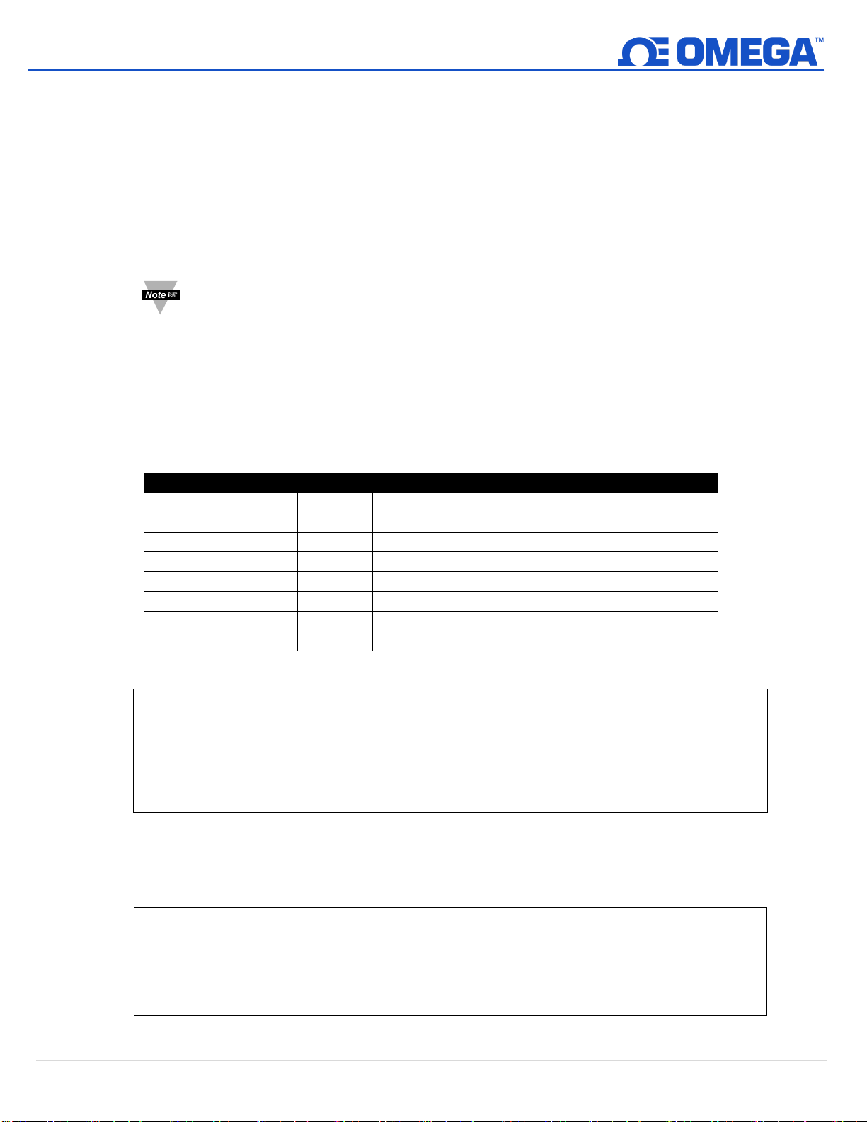
Smart sensor devices use I2C in a request / response configuration, where the IF-001 / IF-002 is always the ‘master’
that initiates requests to the attached smart sensor device. If the attached device wishes to initiate a transaction, a
separate active low interrupt signal (INTR) is provided.
5.9.1 Ignore INTR
If the IF-001 / IF-002 is configured to ignore the INTR signal (I) the corresponding hardware interrupt signal is
disabled. No changes are made to the attached device.
5.9.2 Process INTR
If the IF-001 / IF-002 is configured to process the INTR signal (P) the attached device is preconfigured,
enabling the interrupts indicated below and the hardware interrupt is enabled. A handler is enabled to
process the INTR signals. Upon receipt of an interrupt from the smart sensor device, the IF-001 / IF-002
adaptor will perform the following actions based on the INTERRUPT STATUS bits register read from the
device.
Note: The processing of the INTR signal generates data whenever an interrupt is generated by the
device. This behavior is not compatible with Modbus RTU and the I(nterrupt) processing
mode MUST be set to Ignore if Modbus is to be used.
If the INTR is configured to notify (N), an alternate handler is loaded which will generate a Notify message
consisting of the Interrupt Status read from the device. No change is made to the INTERRUPT CONTROL
register.
24 | M 5 7 57
Page 25

The Notify information consists of the device address (0x68), Register Index (0x?? = Interrupt Status),
number of bytes (0x02), and the value.
Writing to the integer INTERRUPT CONTROL register at location 0x16 allows changing the enabled interrupts.
5.9.3 I2C Address
The IF-001 / IF-002 defaults to using I2C address 0x68. The default may be overwritten by setting the
Address = ??. If a lower case ‘a’ is entered it resets the address back to the default 0x68 value.
5.9.4 Bus Speed
The I2C bus speed defaults to 40 kb/second, suitable for up to 5-meter cable lengths. This may be changed
from values 20 to 100 kbits/second. Note that changing this value will have a minimal impact on overall
performance.
5.9.5 Modbus Address
The IF-001 / IF-002 defaults to Modbus address 0x01, which may be overwritten with the M(odbus) option.
25 | M 5 7 57
Page 26
6 Appendix A: Smart Sensor Register Summary
Name
Type
SS
Register
Modbus
Register
Usage / Comments
DEVICE_ID
u32
0x0000
0xf000
Unique identifier for this device
F/W Version
u32
0x0004
0xf002
Formatted as Major.Minor.Bug.Build
Hardware
Version
u32
0x0008
0xf004
Formatted as Major.Minor.Bug.Build
Device I/O List
selection
u8
0x000c
0xf006
Selects Mix of Sensor / Outputs
User Operating
Hours
u16
0x000e
0xf007
User settable (Hours)
Event 1 Timer
Base
u16
0x0010
0xf008
Used to set internal sampling rate
Event 2 Timer
Base
u16
0x0012
0xf008
Aux timer for application specific use
System Control
u16
0x0014
0xf009
Determines how device behaves
Interrupt Control
u16
0x0018
0xf00c
Determines what generated INTR signal
Number Sensors
u8
0x001a
0xf00d
Number of enumerated sensors
Number Outputs
u8
0x001b
Number of enumerated outputs
Operating
Temperature
u8
0x001c
0xf00e
Operating temperature of device
Operating
Voltage
u8
0x001d
Operating voltage of device
Fault Process
u8
0x001e
0xf00f
Where last fault was detected
Fault Code
u8
0x001f
Type of last fault
Event 1 Timer
u16
0x0020
0xf010
Time remaining on Event Timer 1
Event 2 Timer
u16
0x0022
0xf011
Time remaining on Event Timer 2
System Status
u16
0x0024
0xf012
Overall system status / health
Trigger Request
u16
0x0026
0xf013
Initiates action on device
Extract Start Time
u32
0x0028
0xf014
Used for searching Event Log
Extract End Time
u32
0x002c
0xf016
Used for searching Event Log
Number of
Records
u16
0x0036
0xf01b
Number of records found
Current Time
u32
0x0038
0xf01c
Current time (offset for 2000)
Sensor Readings
(4)
float
0x003c
0xf01e
Four values (consecutive Address)
Log Record Time
u32
0x004c
0xf026
Current time (offset for 2000)
Extracted Values
(4)
float /
u32[4]
0x0050
0xf028
Four values (consecutive Address). May be float or u32
values based on record type
Sensor
Range/Type (4)
u8
0x0062
0xf031
Determine overall sensor type/range. The values are offset
by 0x08 (0x04 Modbus)
Sensor Device (4)
u8
0x0063
Determine overall specific signal configurations. The values
are offset by 0x08 (0x04 Modbus)
Sensor Units (4)
u8[4]
0x0064
0xf032
4 byte string describing units of measure. The values are
offset by 0x08 (0x04 Modbus)
User Parameters
(16)
float
0x0080
0xf040
Application specific user registers (setpoints etc.)
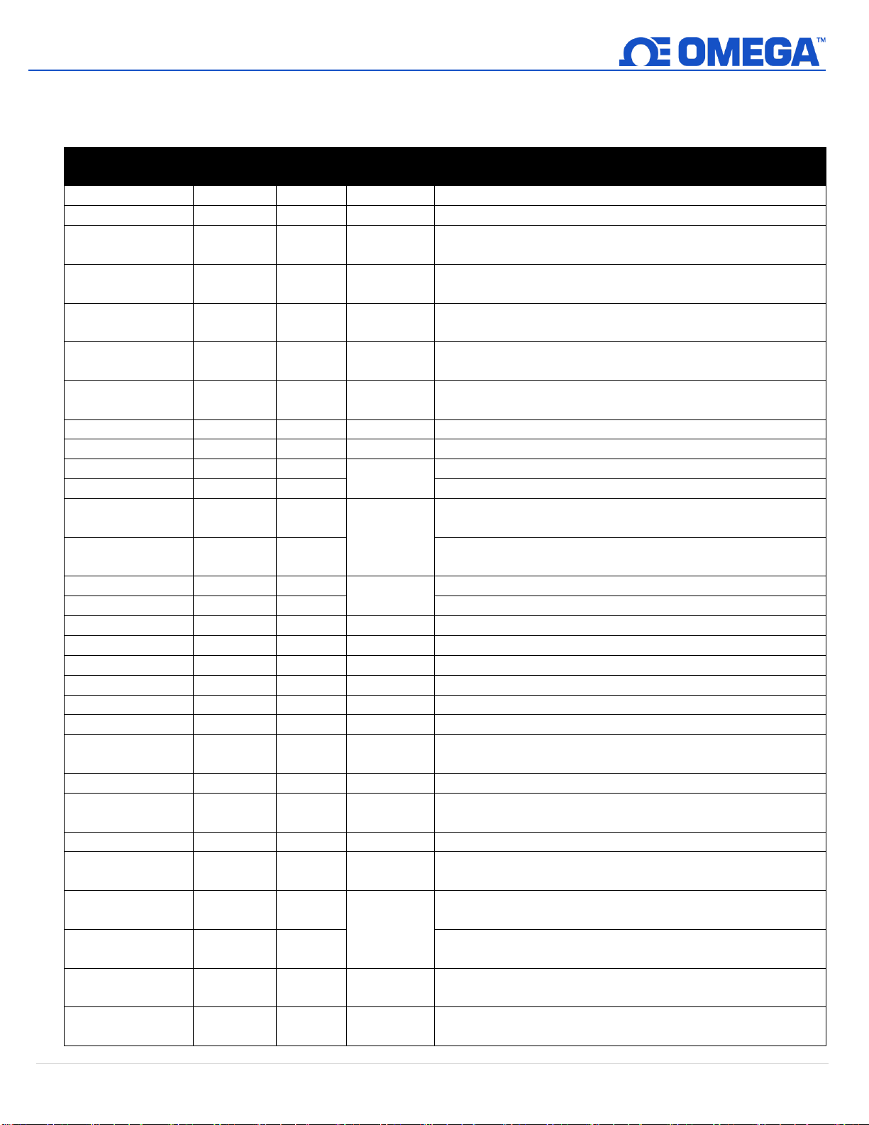
The following is a summary of commonly used smart sensor registers.
26 | M 5 7 57
Page 27
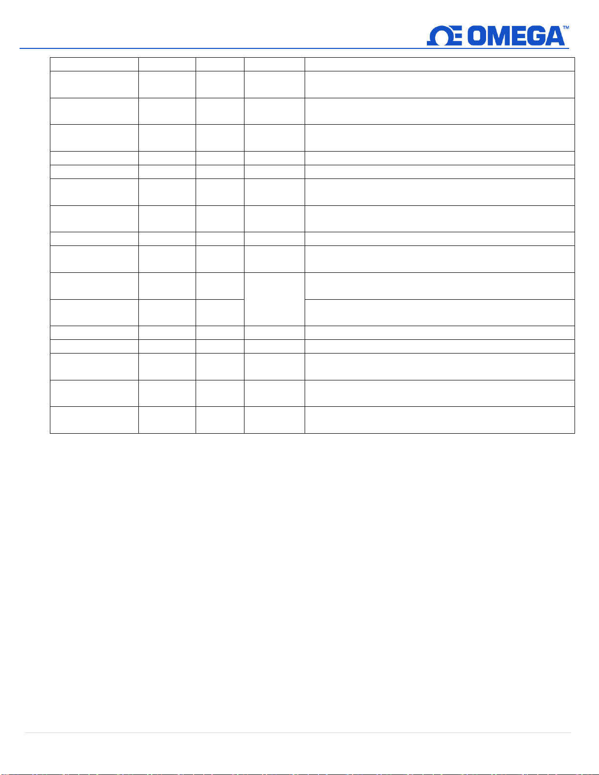
Sensor (16)
float
0x0080
0xf040
Application specific user registers (setpoints etc.)
User Parameters
(16)
float
0x0080
0xf040
Application specific user registers (setpoints etc.)
Sensor Offset (4)
float
0x00c0
0xf060
Offset value for V = R * Gain + Offset applied to Sensor 0, 4
values
Sensor Gain (4)
float
0x00c4
0xf062
Gain value for V = R * Gain + Offset applied to Sensor 0, 4
values
Device Name
u8[16]
0x00e0
0xf070
16 character user assigned device name
Output Values (4)
float
0x00f0
0xf078
4 values represent output values
Manufactured
Date
u16
0x0128
0xf094
Bit formatted as, year offset by 2000
YYYYYYYMMMMDDDDD
Calibration Date
u16
0x012a
0xf095
Bit formatted as, year offset by 2000
YYYYYYYMMMMDDDDD
Operating Time
u32
0x012c
0xf096
Seconds since manufactured
Time since
Calibration
u32
0x012c
0xf096
Seconds since calibrated
Output
Range/Type (4)
u8
0x0134
0xf09a
Determine overall Output type/range. The values are
offset by 0x02 (0x01 Modbus)
Output Device (4)
u8[4]
0x0135
Determine overall specific signal configurations. The values
are offset by 0x02 (0x01 Modbus)
Sensor Names
u8[8]
0xe00
0xf700
4 X sensor name string
Output Names
u8[8]
0xe20
0xf710
4 X output name string
Parameter
Names
u8[8]
0xe40
0xf720
16 X parameter name string
Function Block
Names
u8[8]
0xec0
0xf760
32 X parameter name string
FB Parameter
Names
u8[8]
0xfc0
0xf7e0
4 X Function Block parameter names
27 | M 5 7 57
Page 28
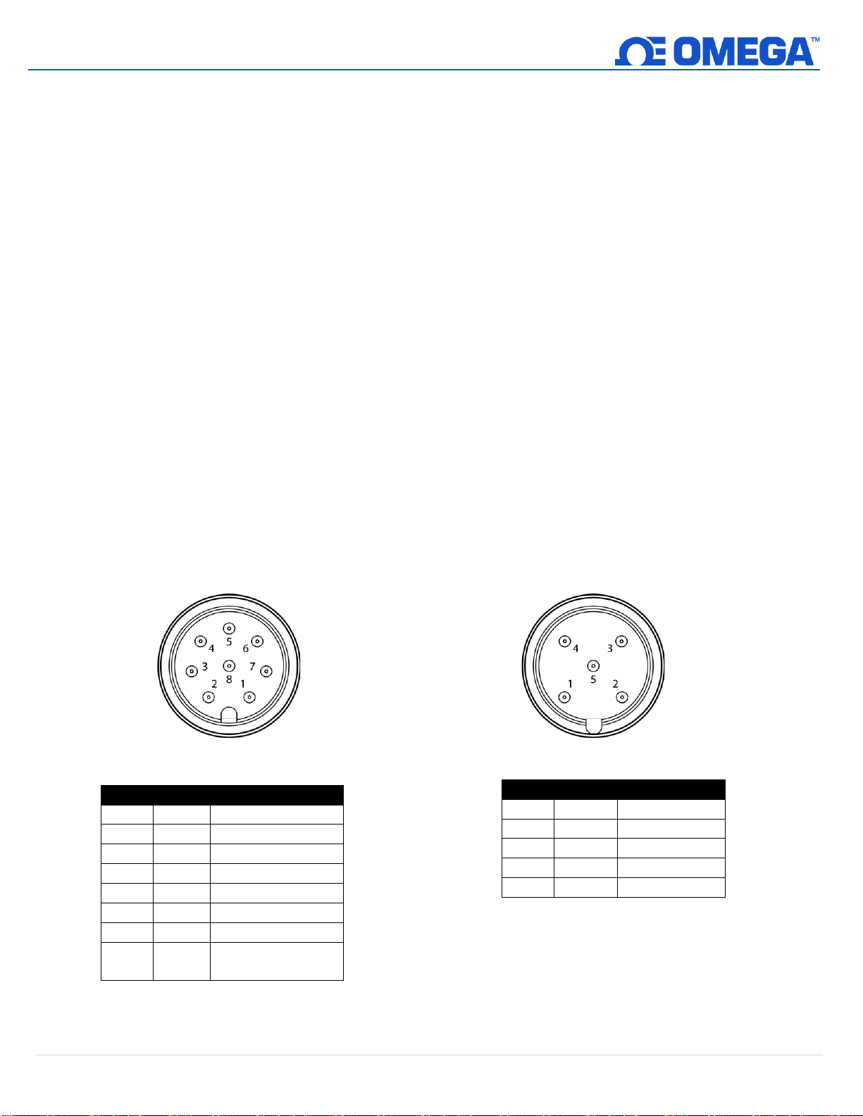
7 Appendix B: Specifications
Name
Function
Pin 1
N/A
No Connection
Pin 2
INTR
Interrupt Signal
Pin 3
SCL
SCL Signal
Pin 4
SDA
SDA Signal
Pin 5
Shield
Shield Ground
Pin 6
N/A
No Connection
Pin 7
GND
Power Return
Pin 8
VCC
Nominal 3.3 VDC to
Smart Probe
Name
Function
Pin 1
VDD
5-36V
DC
Pin 2
A’
RS485 Data +
Pin 3
GND
Ground
Pin 4
B’
RS485 Data -
Pin 5
Shield
Shield Ground
M12 5-Pin Connector (IF-002 Only)
M12 8-Pin Female
Connector Front View
RS485 Serial Port
Baudrate: 9600, 19200, 34800, 115200
Parity: Even, Odd, None
Data Bits: 7, 8
Stop Bits: 1, 2
Protocol: Modbus RTU or Command Line Interpreter
Input Power
Voltage: 5 VDC – 36 V
Output to Smart Probe
100 mA max @ 3.0V ±5%
Environmental
Operating Temperature: -40 to 85°C (-40 to 185°F)
Rating: IP67 when mated
Mechanical
Dimensions: 22.1 mm W x 96.7 mm L (0.87” x 3.80”)
not including mounting tabs
DC
General
Agency Approvals: CE
Compatibility: Windows OS 10 and above. Compatible with OEG, SYNC configuration software,
and Modbus networks
28 | M 5 7 57
Page 29

8 Appendix C: Texas Instrument License Statement
Some elements of Texas Instruments developed software are used in this product. As such, we are required to provide
the following:
--COPYRIGHT, BSD
Copyright (c) 2015, Texas Instruments Incorporated
All rights reserved.
Redistribution and use in source and binary forms, with or without modification, are permitted provided that the
following conditions are met:
Redistributions of source code must retain the above copyright
notice, this list of conditions and the following disclaimer.
Redistributions in binary form must reproduce the above copyright
notice, this list of conditions and the following disclaimer in the
documentation and/or other materials provided with the distribution.
Neither the name of Texas Instruments Incorporated nor the names of
its contributors may be used to endorse or promote products derived
from this software without specific prior written permission.
THIS SOFTWARE IS PROVIDED BY THE COPYRIGHT HOLDERS AND CONTRIBUTORS "AS IS" AND ANY EXPRESS OR
IMPLIED WARRANTIES, INCLUDING, BUT NOT LIMITED TO, THE IMPLIED WARRANTIES OF MERCHANTABILITY AND
FITNESS FOR A PARTICULAR PURPOSE ARE DISCLAIMED. IN NO EVENT SHALL THE COPYRIGHT OWNER OR
CONTRIBUTORS BE LIABLE FOR ANY DIRECT, INDIRECT, INCIDENTAL, SPECIAL, EXEMPLARY, OR CONSEQUENTIAL
DAMAGES (INCLUDING, BUT NOT LIMITED TO, PROCUREMENT OF SUBSTITUTE GOODS OR SERVICES; LOSS OF USE,
DATA, OR PROFITS; OR BUSINESS INTERRUPTION) HOWEVER CAUSED AND ON ANY THEORY OF LIABILITY, WHETHER IN
CONTRACT, STRICT LIABILITY, OR TORT (INCLUDING NEGLIGENCE OR OTHERWISE) ARISING IN ANY WAY OUT OF THE
USE OF THIS SOFTWARE, EVEN IF ADVISED OF THE POSSIBILITY OF SUCH DAMAGE.
--COPYRIGHT--
29 | M 5 7 57
Page 30

WARRANTY/DISCLAIMER
OMEGA ENGINEERING, INC. warrants this unit to be free of defects in materials and workmanship for a
period of 13 months from date of purchase. OMEGA’s WARRANTY adds an additional one (1) month
grace period to the normal one (1) year product warranty to cover handling and shipping time. This
ensures that OMEGA’s customers receive maximum coverage on each product.
If the unit malfunctions, it must be returned to the factory for evaluation. OMEGA’s Customer Service
Department will issue an Authorized Return (AR) number immediately upon phone or written request.
Upon examination by OMEGA, if the unit is found to be defective, it will be repaired or replaced at no
charge. OMEGA’s WARRANTY does not apply to defects resulting from any action of the purchaser,
including but not limited to mishandling, improper interfacing, operation outside of design limits,
improper repair, or unauthorized modification. This WARRANTY is VOID if the unit shows evidence of
having been tampered with or shows evidence of having been damaged as a result of excessive corrosion;
or current, heat, moisture or vibration; improper specification; misapplication; misuse or other operating
conditions outside of OMEGA’s control. Components in which wear is not warranted, include but are not
limited to contact points, fuses, and triacs.
OMEGA is pleased to offer suggestions on the use of its various products. However,
OMEGA neither assumes responsibility for any omissions or errors nor assumes liability for
any damages that result from the use of its products in accordance with information provided
by OMEGA, either verbal or written. OMEGA warrants only that the parts manufactured by the
company will be as specified and free of defects. OMEGA MAKES NO OTHER WARRANTIES OR
REPRESENTATIONS OF ANY KIND WHATSOEVER, EXPRESSED OR IMPLIED, EXCEPT THAT OF
TITLE, AND ALL IMPLIED WARRANTIES INCLUDING ANY WARRANTY OF MERCHANTABILITY
AND FITNESS FOR A PARTICULAR PURPOSE ARE HEREBY DISCLAIMED. LIMITATION OF
LIABILITY: The remedies of purchaser set forth herein are exclusive, and the total liability of
OMEGA with respect to this order, whether based on contract, warranty, negligence,
indemnification, strict liability or otherwise, shall not exceed the purchase price of the
component upon which liability is based. In no event shall OMEGA be liable for
consequential, incidental or special damages.
CONDITIONS: Equipment sold by OMEGA is not intended to be used, nor shall it be used: (1) as a “Basic
Component” under 10 CFR 21 (NRC), used in or with any nuclear installation or activity; or (2) in medical
applications or used on humans. Should any Product(s) be used in or with any nuclear installation or
activity, medical application, used on humans, or misused in any way, OMEGA assumes no responsibility
as set forth in our basic WARRANTY/DISCLAIMER language, and, additionally, purchaser will indemnify
OMEGA and hold OMEGA harmless from any liability or damage whatsoever arising out of the use of the
Product(s) in such a manner.
RETURN REQUESTS/INQUIRIES
Direct all warranty and repair requests/inquiries to the OMEGA Customer Service Department.
BEFORE RETURNING ANY PRODUCT(S) TO OMEGA, PURCHASER MUST OBTAIN AN AUTHORIZED
RETURN (AR) NUMBER FROM OMEGA’S CUSTOMER SERVICE DEPARTMENT (IN ORDER TO AVOID
PROCESSING DELAYS). The assigned AR number should then be marked on the outside of the return
package and on any correspondence.
The purchaser is responsible for shipping charges, freight, insurance and proper packaging to prevent
breakage in transit.
FOR WARRANTY RETURNS, please have the
following information available BEFORE contacting
OMEGA:
1. Purchase Order number under which the product
was PURCHASED,
2. Model and serial number of the product under
warranty, and
3. Repair instructions and/or specific problems
relative to the product.
OMEGA’s policy is to make running changes, not model changes, whenever an improvement is possible. This affords
our customers the latest in technology and engineering.
OMEGA is a trademark of OMEGA ENGINEERING, INC.
© Copyright 2019 OMEGA ENGINEERING, INC. All rights reserved. This document may not be copied, photocopied,
reproduced, translated, or reduced to any electronic medium or machine-readable form, in whole or in part, without the
prior written consent of OMEGA ENGINEERING, INC.
FOR NON-WARRANTY REPAIRS,
OMEGA for current repair charges. Have
the following information available BEFORE
contacting OMEGA:
1. Purchase Order number to cover the COST
of the repair,
2. Model and serial number of the product, and
3. Repair instructions and/or specific problems
relative to the product.
consult
Page 31

Where Do I Find Everything I Need for
Process Measurement and Control?
OMEGA…Of Course!
Shop online at omega.com
TEMPERATURE
MU
Thermocouple, RTD & Thermistor Probes, Connectors, Panels & Assemblies
MU
Wire: Thermocouple, RTD & Thermistor
MU
Calibrators & Ice Point References
MU
Recorders, Controllers & Process Monitors
MU
Infrared Pyrometers
PRESSURE, STRAIN AND FORCE
MU
Transducers & Strain Gages
MU
Load Cells & Pressure Gages
MU
Displacement Transducers
MU
Instrumentation & Accessories
FLOW/LEVEL
MU
Rotameters, Gas Mass Flowmeters & Flow Computers
MU
Air Velocity Indicators
MU
Turbine/Paddlewheel Systems
MU
Totalizers & Batch Controllers
pH/CONDUCTIVITY
MU
pH Electrodes, Testers & Accessories
MU
Benchtop/Laboratory Meters
MU
Controllers, Calibrators, Simulators & Pumps
MU
Industrial pH & Conductivity Equipment
DATA ACQUISITION
MU Communications-Based Acquisition Systems
MU Data Logging Systems
MU Wireless Sensors, Transmitters, & Receivers
MU Signal Conditioners
MU Data Acquisition Software
HEATERS
MU
Heating Cable
MU
Cartridge & Strip Heaters
MU
Immersion & Band Heaters
MU
Flexible Heaters
MU
Laboratory Heaters
ENVIRONMENTAL
MONITORING AND CONTROL
MU
Metering & Control Instrumentation
MU
Refractometers
MU
Pumps & Tubing
MU
Air, Soil & Water Monitors
MU
Industrial Water & Wastewater Treatment
MU
pH, Conductivity & Dissolved Oxygen Instruments
M5757/0223
 Loading...