

Page 1
The 7000 Series Bus Converter
User’s Manual
Warranty
All products manufactured by ICP DAS are under warranty regarding defective
materials for a period of one year from the date of delivery to the original purchaser.
Warning
ICP DAS assumes no liability for damages resulting from the use of this product.
ICP DAS reserves the right to change this manual at any time without notice. The
information furnished by ICP DAS is believed to be accurate and reliable. However, no
responsibility is assumed by ICP DAS for its use, or for any infringements of patents or
other rights of third parties resulting from its use.
Copyright
Copyright 1997 by ICP DAS. All rights are reserved.
Trademark
The names used for identification only may be registered trademarks of their
respective companies.
Revision History
Revision Data Summary of changed
1.5
1.6 2005/02/25
2004/06/07
1. Add the jumper setting for I-7520A on page 14
2. Add the jumper setting for I-7520AR on page 16
1. Add the RS-232’s jumper setting for I-7561 on
page 37
2. Modified the jumper setting for I-7520A/ I-7520A
on page 14/16
1.7 2005/05/15
1.8 2006/01/18
Add the PLUG AND PLAY description for I-7561
on page 37
Correct Jumper setting for I-7551 on page 58
7000 Bus Converter User’s Manual (Version 1.8 Jan/2006, 7PH-006-18) --------------- 1
Page 2

Table of Contents
1. Introduction..........................................................................................................4
1.1 The 7000 series overview...................................................................4
1.2 Related Documentation for the 7000 Series.......................................5
1.3 Common Features of the 7000 Series................................................6
1.4 The 7000 Series System Network for Bus Type.................................7
1.5 7000 Dimension..................................................................................9
2. I-7520/A/R/AR, PCISA-7520AR, PCISA-7520R..................................................11
2.1 I-7520:.............................................................................................. 11
2.1.1 Pin Assignment and Specifications:................................................11
2.1.2 Block Diagram .............................................................................. 11
2.2 I-7520R:............................................................................................12
2.2.1 Pin Assignment and Specifications:................................................12
2.2.2 Block Diagram: .............................................................................12
2.3 I-7520A:............................................................................................13
2.3.1 Pin Assignment and Specifications:................................................13
2.3.2 Block Diagram: ...............................................................................13
2.3.3 The I-7520A has three different output types..................................14
2.4 I-7520AR : ........................................................................................15
2.4.1 Pin Assignment and Specifications:................................................15
2.4.2 Block Diagram: ..............................................................................15
2.4.3 The I-7520AR has three different output types...............................16
2.5 PCISA-7520AR Pin Assignment and Specification:........................17
2.6 PCISA-7520R Pin Assignment and Specification:............................18
2.7 Basic Wire Connection for I-7520:....................................................19
2.8 How to select 7520 / 7520R .............................................................20
3. USB series: I-7560 / I-7561 / I-7563....................................................................24
3.1 I-7560 Pin Assignment and Specifications:....................................25
3.1.1 The I-7560 System Network Configuration:....................................26
3.1.2 Block Diagram: ...............................................................................26
3.1.3 I-7560 Driver Installation.................................................................27
3.1.4 Verifying the Installation:.................................................................31
3.1.5 Uninstalling the Device Driver.........................................................34
3.2 I-7561 Pin Assignment and Specifications........................................35
3.2.1 The I-7561 System Network Configuration:....................................36
3.2.2 The I-7561 Block Diagram:............................................................36
7000 Bus Converter User’s Manual (Version 1.8 Jan/2006, 7PH-006-18) --------------- 2
Page 3

3.2.4 I-7561 Driver Installation.................................................................38
3.2.5 Verifying the Installation:.................................................................42
3.2.6 Uninstalling the Device Driver.........................................................45
3.3 I-7563 Pin Assignment and Specifications:....................................46
3.3.1 The I-7563 System Network Configuration:....................................47
3.3.2 The I-7563 Block Diagram:.............................................................47
3.3.3 I-7563 Driver Installation.................................................................48
3.3.4 Verifying the Installation:.................................................................52
3.3.5 Uninstalling the Device Driver.........................................................55
4. I-7551 : RS-232 to RS-232 Converter ................................................................56
4.1 I-7551 Pin Assignment and Specifications:.......................................56
4.1.1 The I-7551 System Network Configuration:....................................57
4.1.2 The I-7551 Block Diagram:.............................................................57
4.1.3 I-7551 has two different output types.
5. Repeater series: I-7510 / I-7510A / I-7510AR / I-7513.......................................59
5.1 I-7510:..............................................................................................59
5.1.1 Pin Assignment and Specifications:................................................59
5.1.2 Block Diagram: ...............................................................................59
5.2 I-7510A:............................................................................................60
5.2.1 Pin Assignment and Specifications:.............................................60
5.2.2 Block Diagram: .............................................................................60
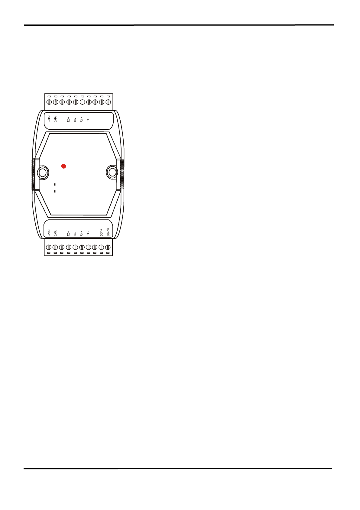
5.3 I-7510AR: .........................................................................................61
5.3.1 Pin Assignment and Specifications:................................................61
5.3.2 System Network Configuration: ......................................................62
5.3.3 Block Diagram: ...............................................................................62
5.4 I-7513:...........................................................................................63
5.4.1 Pin Assignment and Specifications:...............................................63
5.4.2 System Network Configuration: ......................................................64
5.4.3 Block Diagram: .............................................................................64
5.5 Basic Wire Connections for I-7510...................................................65
6. 7000 RS-485 Networking ...................................................................................66
6.1 Standard/Isolation Configuration.......................................................66
6.2 PLC Networking Applications ...........................................................70
6.3 PC Networking Applications .............................................................71
6.4 RS-232 Devices Network .................................................................72
7000 Bus Converter User’s Manual (Version 1.8 Jan/2006, 7PH-006-18) --------------- 3
Page 4

1. Introduction
The 7000 series is a family of remote controllable data
acquisition modules. They provide A/D, D/A, DI/O, Timer/Counter,
MMI and other functions. These modules can be controlled
remotely by a set of commands.
1.1 The 7000 series overview The 7000 series can be divided into several groups based on their
function as follows:
Group 1: bus converter modules, support bus converter & repeater
7520/7520R/ISA-7520R/PCISA-7520R: RS-232 to RS-485
converter, 3000V isolation.
7520A: RS-232 to RS485 and RS-422 converter, 3000V
isolation.
7520AR/PCI-7520AR: RS-232 to RS485 and RS-422 converter,
3000V isolation.
7560: USB to RS-232 converter.
7561: USB to RS-232/422/485 converter, 3000V isolation.
7563: USB to 3-Channel 485 converters, 3000V isolation.
7510: RS-485 to RS-485 repeater, 3000V isolation
7510A: RS-485 and RS-422 repeater, 3000V isolation
7510AR: RS-485 and RS-422 repeater, Two-way 3000V isolation
7551: RS-232 to RS-232 Converter
7513: One RS-485 to three channels RS-485 Hub
Group 2: DIO modules, support TTL, isolated DIO, relay & O. C.
Output
7041: isolated DI, 14*in
7042: isolated O. C. DO, 13*Out
7043: No isolated O.C. 16 channels digital output.
7044: high driver O.C. output I + isolated DI, 4*In+8*Out
7050: TTL IO, 7*In, 8*Out
7052: isolated DI, 8*in
7053: Non-isolated DI, 16*In
7060: isolated DI & relay output, 4*In+4*Relay
7063: isolated DI *8 & 3 form A power relay.
7065: isolated DI *4 & 5 form A power relay.
7066: 7 form A PhotoMOS Relay
7067: Relay output, 7*Relay
7000 Bus Converter User’s Manual (Version 1.8 Jan/2006, 7PH-006-18) --------------- 4
Page 5

Group 3: DA module, support voltage/current output.
7021: 1 channel analog output.
7022: 2 channel analog output.
7024: 4 channel analog output.
Group 4: AD modules, support voltage/current/thermocouple/RTD
measurement
7011/7011D/7011P: single-channel thermocouple measurement
7012/7012D/7012F: single-channel large signal measurement
7013/7013D: 1 channel RTD measurement
7033/7033D: 3 channels RTD measurement
7014D: Analog/Transmitter input with LEDs display
7016/7016D/7016P: Strain Gauge input with LEDs display
7017/7018F: Input Range and multi-channel same as 7012.
7018: Thermocouple input, multi-channel 7011
Group 5: Timer/Counter modules: 7080, 7080D
Group 6: Man Machine Interface: MMICON=240*64 LCD+4*4
KBDs+8*function key
Group 7: Power relay Modules:
RM104/108/116: 4/8/16 channels of form-C, SPST, 400V AC, 16A
RM204/208/216: 4/8/16 channels of form-C, SPDT, 400V AC, 5A
Group 8: Embedded Processor module
7188, 7188XA, 7188XB, 7188XC, 7188EX, 7188EA
Group 9: wireless modem module: SST-2450
Group 10: Power supply module
ACE-540A: 24V/2A power supply
DIN-540A: ACE-540A with DIN-RAIL mount
PWR-24/220V: 220V AC input, 24V/0.1A output power adapter
PWR-24/110V: 110V AC input, 24V/0.1A output power adapter
1.2 Related Documentation for the 7000 Series
• 7000 Bus Converter User Manual:
For 7510/7520/7520A/7520R/7561/7510A/7520AR/ISA-7520A/
PCI-7520AR/PCISA-7520R
• 7000 DIO User Manual: for 7050/7052/7053/7060/7041/7042/7044/7067
• 7000 A/D Group1 User Manual: for
7017/7018/7013/7013D/7033/7033D
• 7000 A/D Group2 User Manual: for 7011/7011D/7012/7012D/7014D
• 7000 D/A User Manual: for 7021, 7022, and 7024.
• 7000 Timer/Counter User Manual: for 7080D
• 7000 Embedded Controller User Manual: for 7188
7000 Bus Converter User’s Manual (Version 1.8 Jan/2006, 7PH-006-18) --------------- 5
Page 6

• MMICON Hardware Manual: for MMICON
• MMIDOS User Manual: for MMICON software
• Application Note: EM001 Æ for MMICON evaluation
1.3 Common Features of the 7000 Series Isolation voltage: 3000 VDC
Communication:
• Asynchronous half-duplex 2-wire RS-485 network
• Max. Distance without repeater= 1.2Km
• Speed=1200,2400,4800,9600,19200,38400,57600,115200
• Connecting 256 modules in one RS-485 bus without repeater
• Multiple baud rate and multiple data format can share the same
RS-485 bus (7520/7510)
• Different baud rate and the same module address can share the same
RS-485 bus
• Connecting 256*8=2048 modules max. In one RS-485 bus with
repeater.
• 7000 series data format=1 start + 8 data + 1 stop + no parity = 10-bit
• Two extra checksum bytes can be enable/disable
• Built-in transient voltage suppresser and PTC protector
• Sharing the same RS-485 bus with the RS-485 or RS-232 device,
which communicates in multiple data format (not 10-bit) and multiple
bauds Rate. (Use 7520 to convert RS-232 to RS-485)
Power requirement:
• Unregulated +10V dc ~ +30V dc.
• Power reverse protection, Over-voltage brown-out protection
System:
• Dual watchdog inside, power-on start value and safe value for host
failure
• Operating temperature: -25 to 75ºC (14 to 185ºF)
• Storage temperature: -25 to 80ºC (-13 to 185ºF)
• Humidity: 5 to 95%, non-condensing
7000 Bus Converter User’s Manual (Version 1.8 Jan/2006, 7PH-006-18) --------------- 6
Page 7
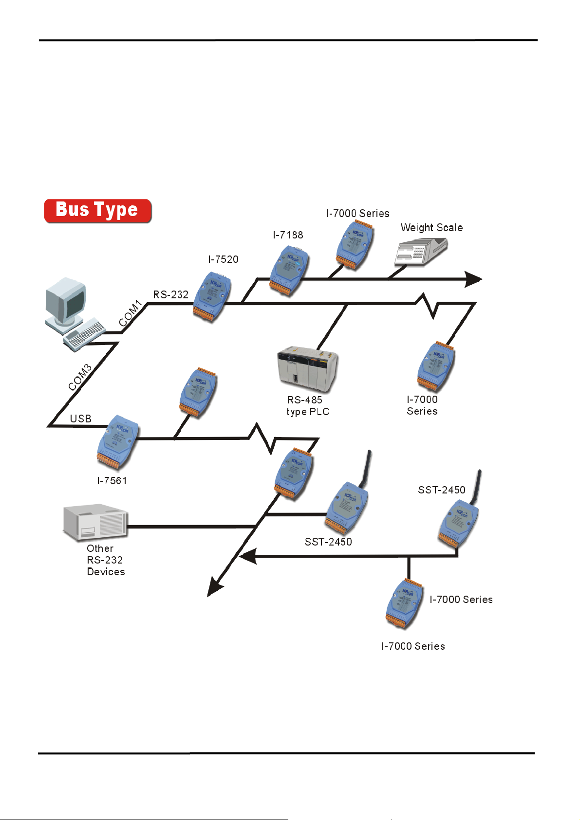
1.4 The 7000 Series System Network for Bus Type
• Multiple Baud Rate
• Multiple Data Format
7000 Bus Converter User’s Manual (Version 1.8 Jan/2006, 7PH-006-18) --------------- 7
Page 8

Conventional Two-Wire RS-485 Network: The conventional two-wire RS485 network uses a DIP SWITCH selectable converter to convert host
RS-232 or USB signals to a two-wire RS-485 signal. The baud rate and
data format must be
set to a fixed value for the whole network. For
example, the user can choose baud rate=9600 and data format=10 bit per
character. This limitation is inconvenient for some real world applications.
The 7000 series, Adam 4000 series, Nudam 6000 series and
DATAFORTH 9B series all use a 10-bit format. Some conventional PLCs
use an 11-bit data format and some weight scale equipment uses 12-bit. If
the host-PC needs to send commands to remote modules, PLCs and
weight scale equipment, one possibility is to use
three independent twowire RS-485 networks. However, this may increase system cost and
reduce system reliability.
Another option for real world applications is to use many modules in the
same two-wire RS-485 network.
Each module must communicate at the
same baud rate in a conventional system. Some module may be very
close to the host-PC and will be able to communicate at a higher baud
rate. Other modules may be farther away from the host-PC and will
communicate at a lower baud rate. Since only one speed is valid in an
RS-485 network, the higher speed modules should be
forced to
communicate at a lower speed baud rate. In other words, the
performance of the entire system must be decreased.
The 7000 Series RS-485 Network: The 7000 RS-485 network is the
most powerful and flexible two-wire RS-485 networks in the world. It is
a
multiple baud rate and multiple data format network system. That is to
say, all the remote modules mentioned above, PLCs and weight scale
equipment
485 converter, equips a “Self Tuner” inside, therefore it can
share the same RS-485 network. The 7520, RS-232 to RS-
detect the
baud rate and data format automatically and control the direction of the
RS-485 network precisely. Therefore the user can connect all this
equipment to the same RS-485 network.
This method will greatly
reduce system cost and increase reliability.
7000 Bus Converter User’s Manual (Version 1.8 Jan/2006, 7PH-006-18) --------------- 8
Page 9
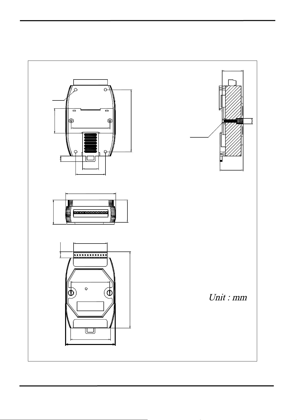
1.5 7000 Dimension
O4.5X4
29.50
35.30
33.00
56.00
7.30
25.00
40.50
88.50
2-SCREW
M3
33.00
8
Back View
72.00
25.00
Side View
Top View
50.00
10.50
56.00
111.00
58.50
72.00
From View
7000 Bus Converter User’s Manual (Version 1.8 Jan/2006, 7PH-006-18) --------------- 9
Page 10
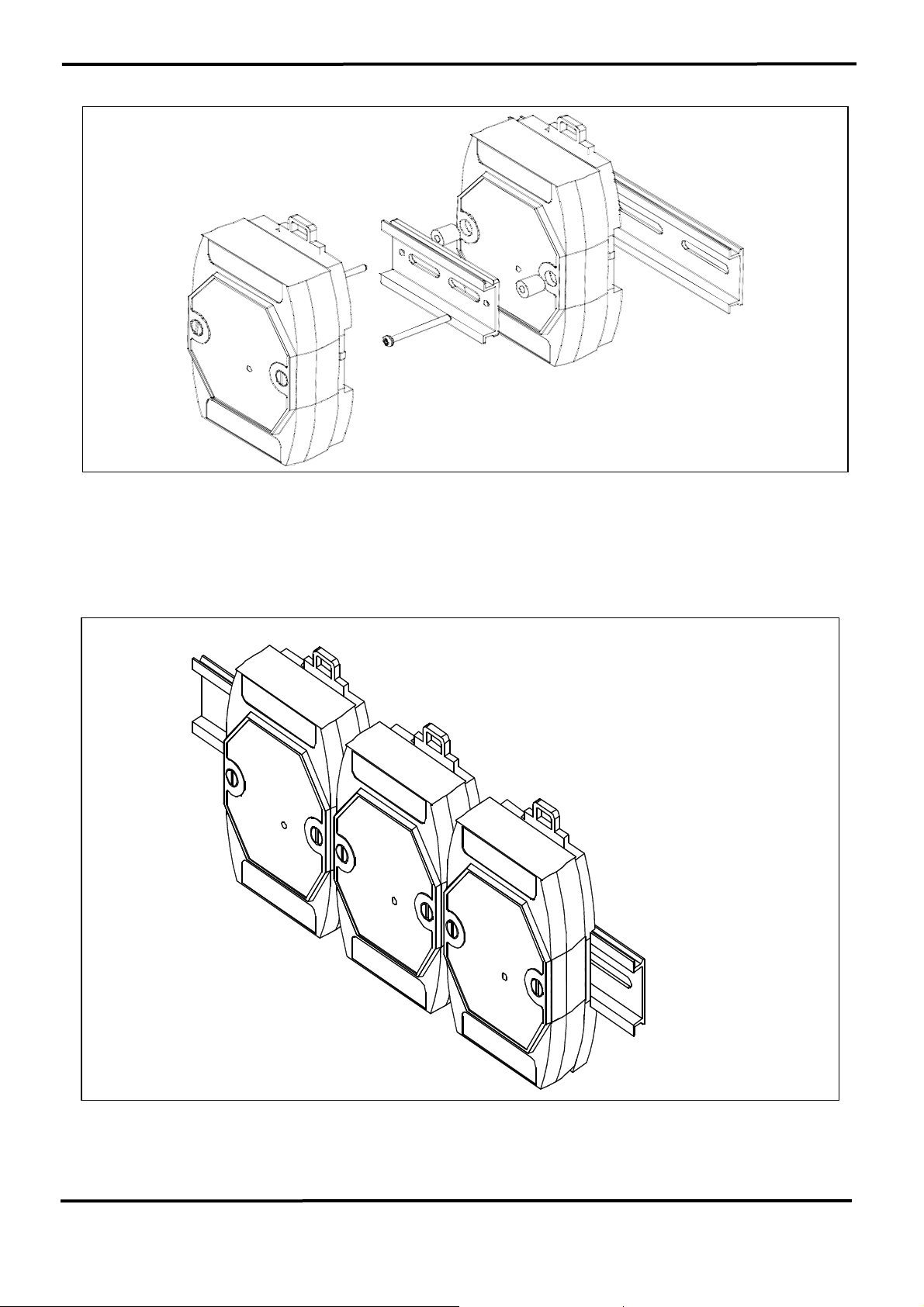
Stack Mounting
Din – Rail Mounting
7000 Bus Converter User’s Manual (Version 1.8 Jan/2006, 7PH-006-18) --------------- 10
Page 11
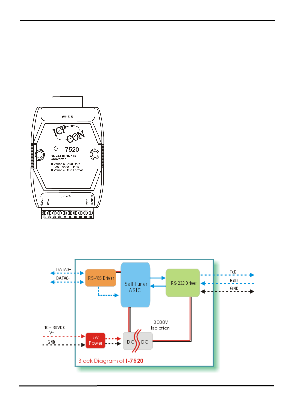
2. I-7520/A/R/AR, PCISA-7520AR, PCISA-7520R
2.1 I-7520:
2.1.1 Pin Assignment and Specifications:
7520: RS-232 to RS-485 Converter
• Protocol: Differential 2-wire half-duplex RS-485
• Connector: plug-in screw terminal block
• Speed: “Self Tuner” inside, auto switching baud
rate, from 300 to 115200 bps
• 256 modules max in one RS-485 network
without repeater
• 2048 modules max in one RS-485 network with
repeater
• Isolation voltage: 3000V
• Isolation site: RS-232
• Repeater request: 4,000 feet or over 256
modules
• Power requirements: +10V dc ~ +30V dc
• Power consumption: 0.05A@24V; Max
2.1.2 Block Diagram
7000 Bus Converter User’s Manual (Version 1.8 Jan/2006, 7PH-006-18) --------------- 11
Page 12
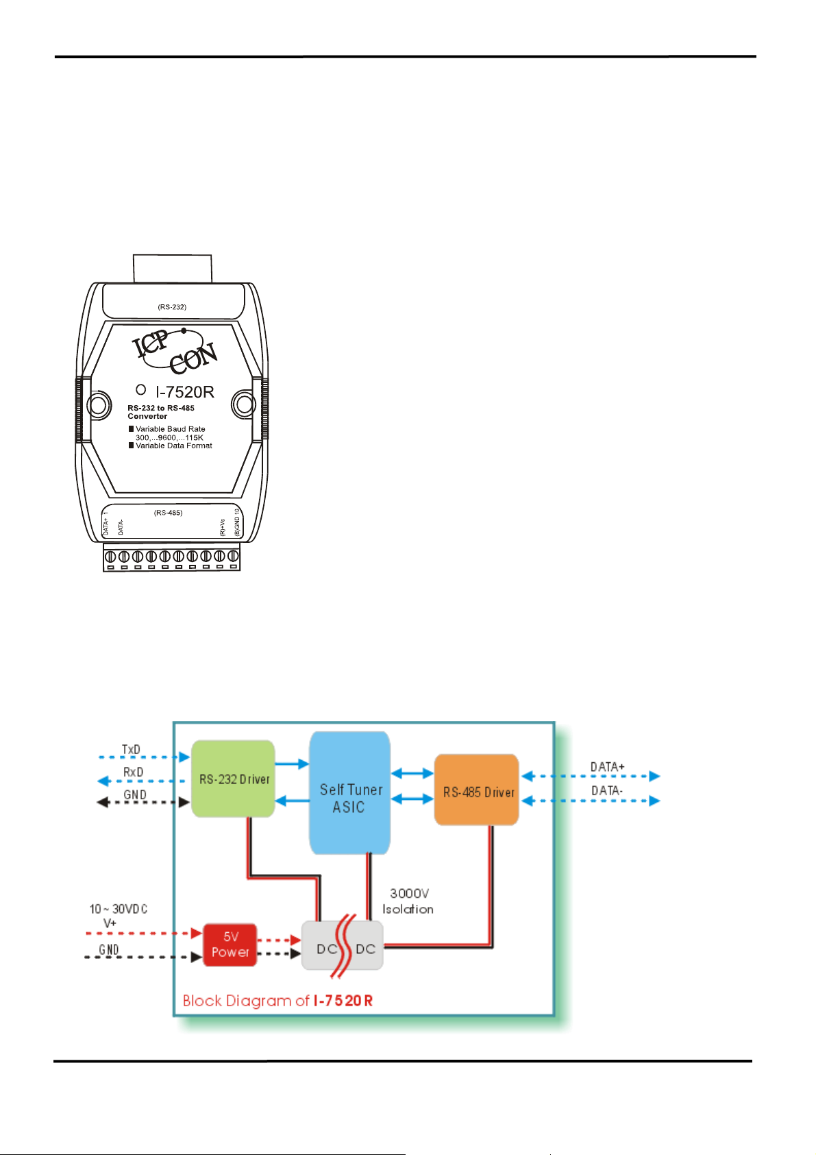
2.2 I-7520R:
2.2.1 Pin Assignment and Specifications:
7520R: RS-232 to RS-485 Converter
• Protocol: two-wire RS-485, (D+, D-), protocol
• Connector: plug-in screw terminal block
• Speed: “Self Tuner” inside, auto switching baud
rate, from 300 to 115200 BPS
• 256 modules max in one RS-485 network
without repeater
• 2048 modules max in one RS-485 network with
repeater
• Isolation voltage: 3000V
• Isolation site: RS-485
• Repeater request: 4,000 feet or over 256
modules
• Power requirements: +10V dc ~ +30V dc
• Power consumption: 0.05A@24V; Max
2.2.2 Block Diagram:
7000 Bus Converter User’s Manual (Version 1.8 Jan/2006, 7PH-006-18) --------------- 12
Page 13
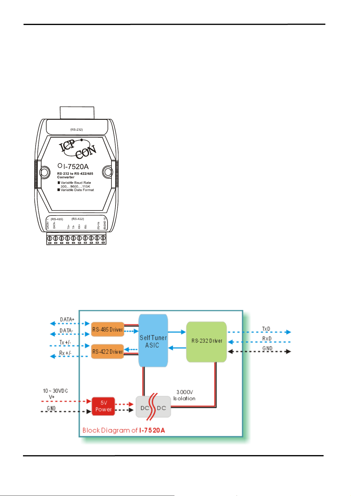
2.3 I-7520A:
2.3.1 Pin Assignment and Specifications:
7520A: RS-232 to RS-422/485 Converter
• Protocol: RS-422/485
• Connector: plug-in screw terminal block
• Speed: “Self Tuner” inside, auto switching baud
rate, from 300 to 115200 BPS
• 256 modules max in one RS-485 network
without repeater
• 2048 modules max in one RS-485 network with
repeater
• Isolation voltage: 3000V
• Isolation site: RS-232
• Repeater request: 4,000 feet or over 256
modules
• Power requirements: +10V dc ~ +30V dc
• Power consumption: 0.05A@24V; Max
2.3.2 Block Diagram:
7000 Bus Converter User’s Manual (Version 1.8 Jan/2006, 7PH-006-18) --------------- 13
Page 14
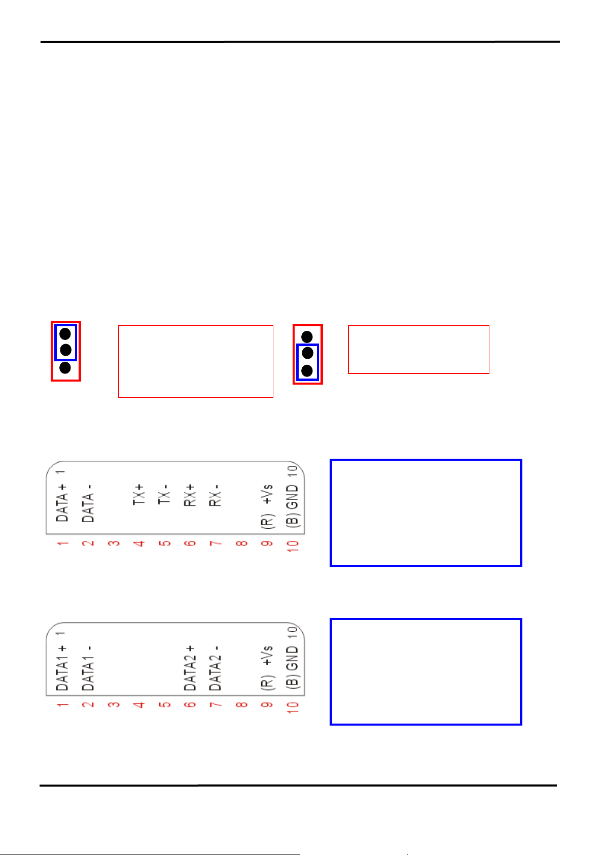
2.3.3 The I-7520A has three different output types
Selecting the I-7520A output type.
NOTE: The RS-422 and RS-485 output types couldn’t be used
simultaneously, which means that you can only select 1 type to output.
Type 1: 1-channel RS-485 output.
Type 2: 1-channel RS-422 output.
Type 3: 2-channel RS-485 output. (Support star network)
RS422/485 Output Jumpers settings:
For type 1: Set the JP1 jumper to positions 2 and 3.
For type 2: Set the JP1 jumper to positions 2 and 3.
For type 3: Set the JP1 jumper to positions 1 and 2.
JP1
3
2
1
Types 1 and 2:
Default setting
RS-422 or RS-485
JP1
3
Type 3:
2
2-channel RS-485
1
Pin Assignment For type1 and type2:
Pin Assignment For type3:
RS-485 Pin define:
DATA+ and DATA-
RS-422 Pin define:
TX+, TX-, RX+ and RX-
Channel one Pin define:
DATA1+ and DATA1-
Channel two Pin define:
DATA2+ and DATA2-
7000 Bus Converter User’s Manual (Version 1.8 Jan/2006, 7PH-006-18) --------------- 14
Page 15
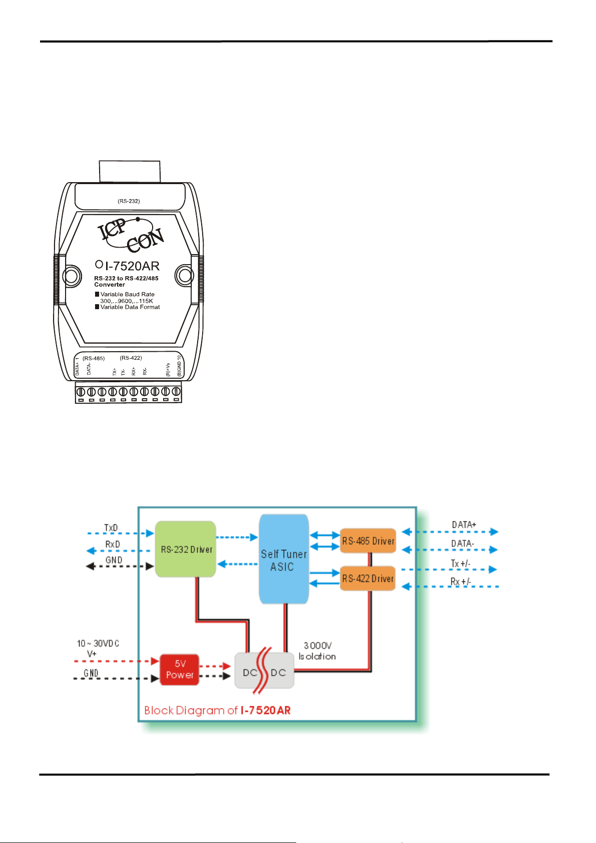
2.4 I-7520AR :
2.4.1 Pin Assignment and Specifications:
7520AR: RS-232 to RS-422/485 Converter
• Protocol: RS-422/485
• Connector: plug-in screw terminal block
• Speed: “Self Tuner” inside, auto switching baud
rate, from 300 to 115200 BPS
• 256 modules max in one RS-485 network
without repeater
• 2048 modules max in one RS-485 network with
repeater
• Isolation voltage: 3000V
• Isolation site: RS-422/485
• Repeater request: 4,000 feet or over 256
modules
• Power requirements: +10V dc ~ +30V dc
• Power consumption: 0.05A@24V; Max
2.4.2 Block Diagram:
7000 Bus Converter User’s Manual (Version 1.8 Jan/2006, 7PH-006-18) --------------- 15
Page 16
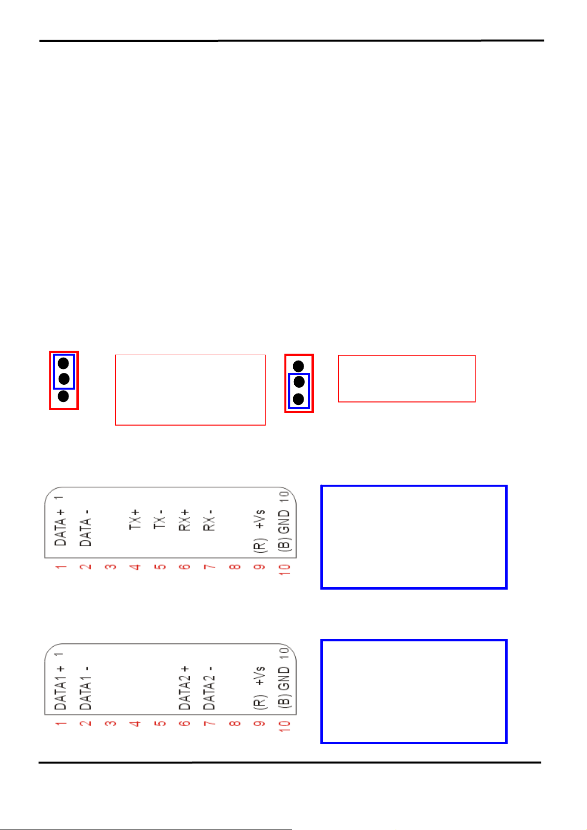
2.4.3 The I-7520AR has three different output types
Selecting the I-7520AR output type.
NOTE: The RS-422 and RS-485 output types couldn’t be used simultaneously,
which means that you can only select 1 type to output.
Type 1: 1-channel RS-485 output.
Type 2: 1-channel RS-422 output.
Type 3: 2-channel RS-485 output. (Support star network)
RS422/485 Output Jumpers settings:
For type 1: Set the JP1 jumper to positions 2 and 3.
For type 2: Set the JP1 jumper to positions 2 and 3.
For type 3: Set the JP1 jumper to positions 1 and 2.
JP1
3
2
1
Types 1 and 2:
Default setting
RS-422 or RS-485
JP1
3
Type 3:
2
2-channel RS-485
1
Pin Assignment For type1 and type2:
RS-485 Pin define:
DATA+ and DATA-
RS-422 Pin define:
TX+, TX-, RX+ and RX-
Pin Assignment For type3:
Channel one Pin define:
DATA1+ and DATA1-
Channel two Pin define:
DATA2+ and DATA2-
7000 Bus Converter User’s Manual (Version 1.8 Jan/2006, 7PH-006-18) --------------- 16
Page 17
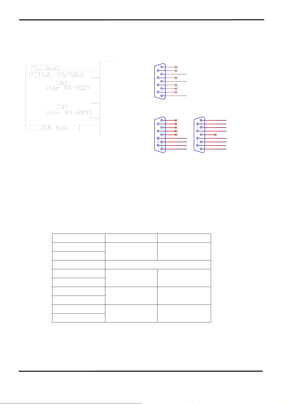
2.5 PCISA-7520AR Pin Assignment and Specification:
CN1
1
6
RXD
2
7
3
TXD
8
4
9
5
GND
DB9M FEMALE
CN2
5
9
4
8
3
D-
7
D+
2
D-
6
D+
1
DB9S MALE
R S-485 ( D+, D- ) R S-422 ( RX+, R X-, TX+, T X- )
CN2
DB9S MALE
RX+
5
RX-
9
RX+
4
RX-
8
3
TX-
7
TX+
2
TX-
6
TX+
1
CON2: RS-485/422 DB9 Male Connector
Terminal 2-wire RS-485 4-wire RS-422
1
DATA+ TX+
2
3 Not Connect
4
Not Connect RX+
5
6
DATA- TX-
7
8
Not Connect RX-
9
The PCISA-7520AR is exactly the same as 7520AR except for the PCI
and ISA interface. It is designed for easy installation.
7000 Bus Converter User’s Manual (Version 1.8 Jan/2006, 7PH-006-18) --------------- 17
Page 18
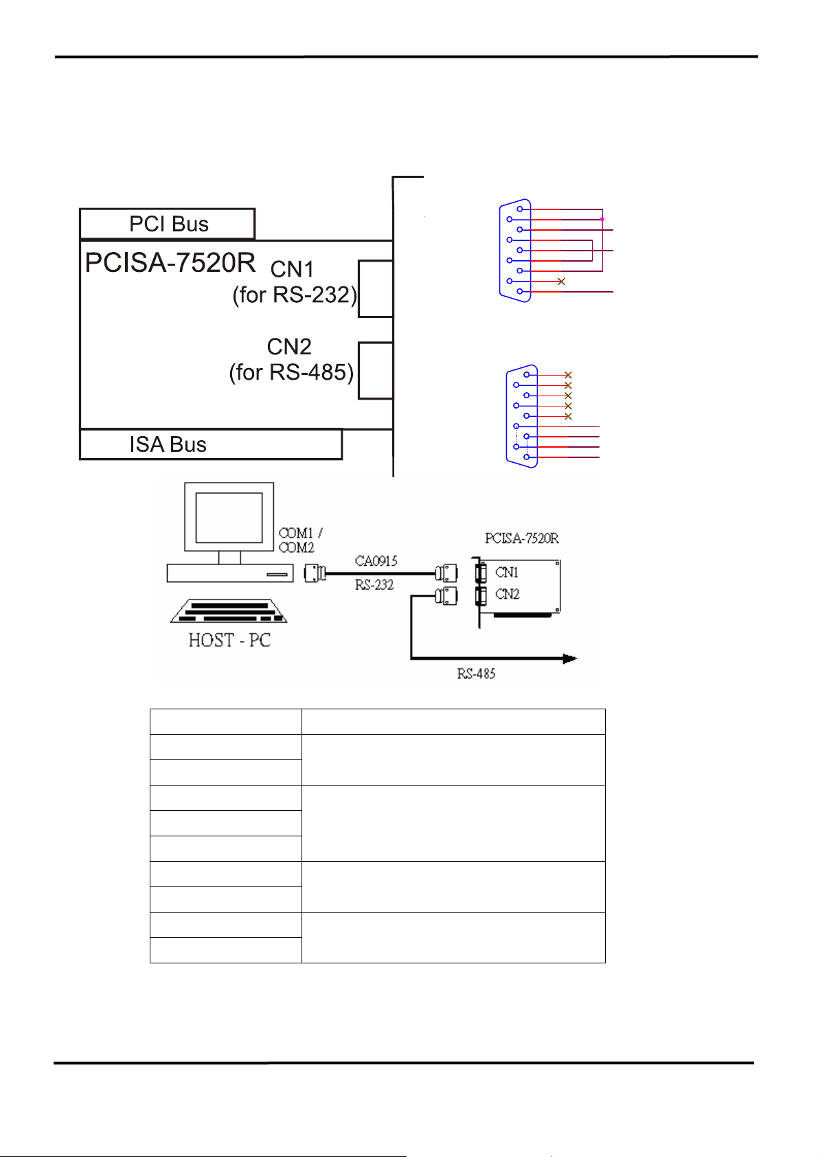
2.6 PCISA-7520R Pin Assignment and Specification:
CN1
DB9M FEMALE
CN2
DB9S MALE
RS-485 ( D+, D- )
DCD
1
DSR
6
RXD
2
RTS
7
TXD
3
CTS
8
DTR
4
9
GND
5
5
9
4
8
3
D-
7
D+
2
D-
6
D+
1
CON2: RS-485 DB9 Male Connector
Terminal 2-wire RS-485
1
DATA+
2
3
4
Not Connect
5
6
DATA-
7
8
Not Connect
9
The PCISA-7520R is exactly the same as 7520R except for the PCI and
ISA interface. It is designed for easy installation.
7000 Bus Converter User’s Manual (Version 1.8 Jan/2006, 7PH-006-18) --------------- 18
Page 19
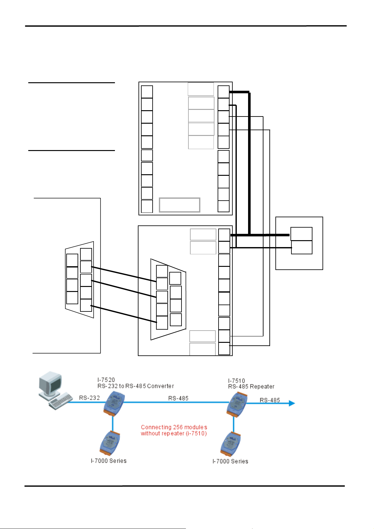
2.7 Basic Wire Connection for I-7520:
RS 485 wire connection.
GND ÅÆ Ext. Power GND
+VS Å Æ Ext. Power 10V-30V
Data-ÅÆ DataData+ÅÆ Data+
RS 232 wire connection
Host pin2 (RXD) ÅÆ 7520_Pin2
Host pin3 (TXD) ÅÆ 7520_Pin3
Host pin5 (GND) ÅÆ 7520_Pin5
Host Computer
6
7
8
9
1
2
3
4
5
Male 9-pin D-sub
Com 1/2/3/4 or
UART port
RS-232C
Signal
11
12
13
14
15
17
18
19
7000
20
7520
7520R
1
2
3
4
5
GND
+VS
DataData+
Init*
+VS
6
7
8
9
Date+
10
9
8
7
6
5
4
3
2
10
9
8
7
6
5
RS-485
Signal
3
2
1
GND
24V
External power
Female 9-pin D-sub
7000 Bus Converter User’s Manual (Version 1.8 Jan/2006, 7PH-006-18) --------------- 19
Page 20
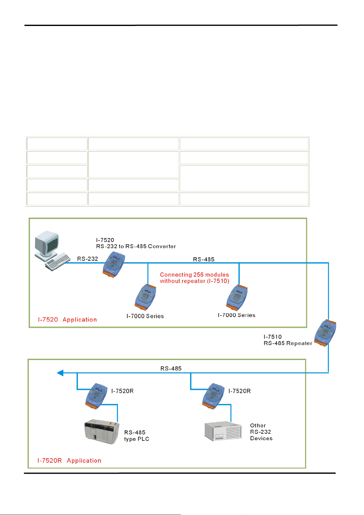
2.8 How to select 7520 / 7520R
The 7520R is exactly the same as 7520 except for the isolation site.
The isolation site of the 7520 is located in the RS-232 interface circuit,
but the isolation site of the 7520R is located in the RS-485 interface
circuit. That is to say, the power input and RS-485 interface is common
ground for the 7520 but the power input and RS-232 interface is only
common ground for the 7520R as follows:
7520 7520R
RS-485 site Isolation site
Common ground
Power ground
Common ground
RS-232 site Isolation site
Applications Most applications. For RS-232 type PLC networking
7000 Bus Converter User’s Manual (Version 1.8 Jan/2006, 7PH-006-18) --------------- 20
Page 21
A
Note: the power ground of q7000
and rRS-485 is
ground.
dam 4000, Nudam 6000 and
DATAFORTH 9B series modules.
This is the same for
common
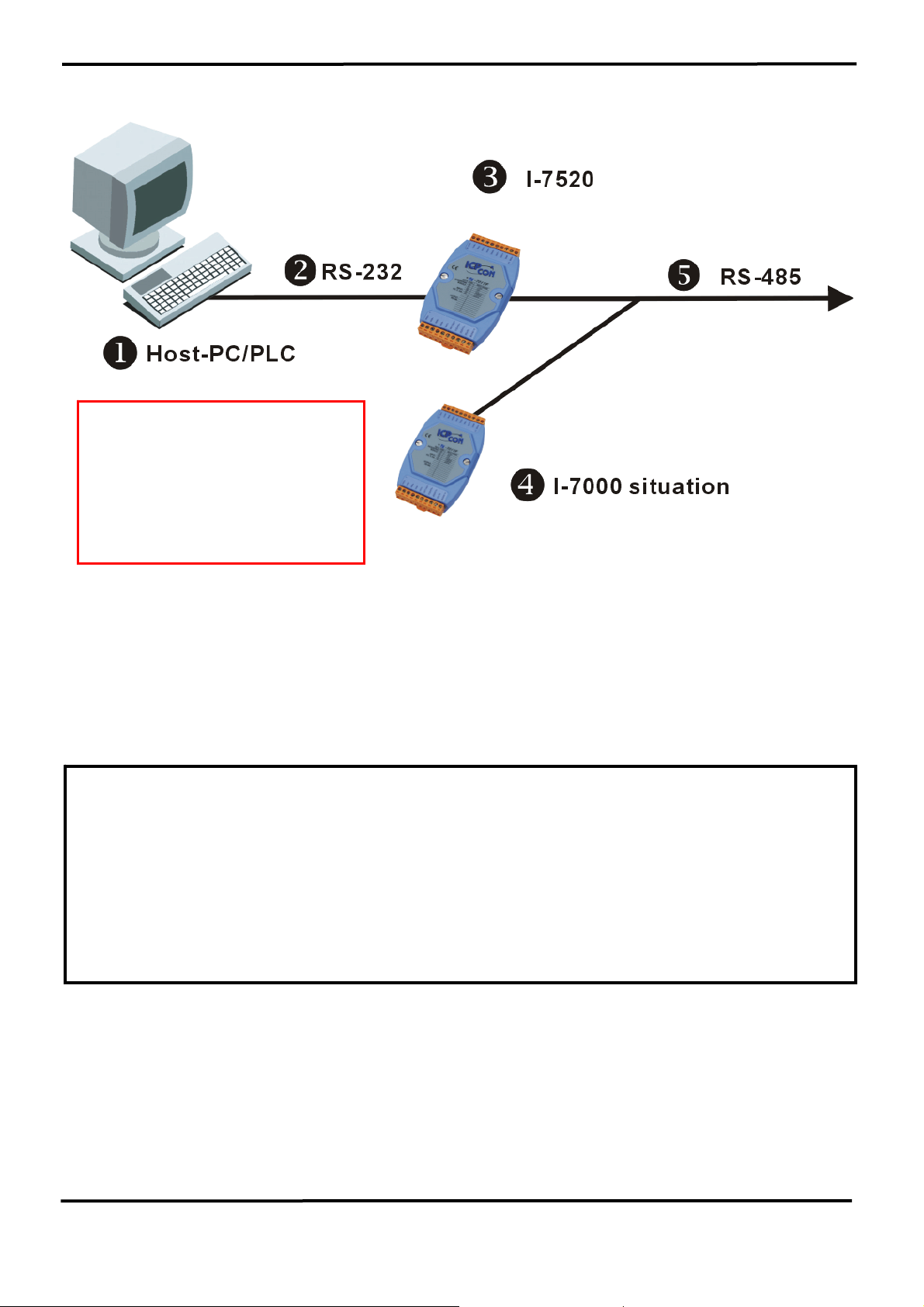
In most applications, the p7520 are used to convert the oRS-232 signal to
rRS-485 network. Normally the p7520 does not use the same DC power
ground as the nHost PC/PLC, and the isolation site is in the RS-232 section.
Therefore the nHost PC/PLC is isolated from rRS-485 network. That is to say,
if there is any high voltage transient on rRS-485 network, the nHost PC/PLC
will be free from damage.
WARNING!! ERROR CONDITION 1: if the p7520 are replaced by p7520R and
the p7520R uses the same DC power ground with q7000. In this situation,
(1) The nHost PC/PLC is common ground with oRS-232
(2) The oRS-232 is common ground with power ground of p7520R
(3) The power ground of p7520R is common ground with power ground of
q7000
(4) The power ground of q7000 is common ground with rRS-485
Therefore the nHost PC/PLC is common ground with rRS-485 network.
That is to say, there is no isolation between nHost PC/PLC and rRS-485
network. The nHost PC/PLC may be damaged if there is high voltage transient
on rRS-485 network.
7000 Bus Converter User’s Manual (Version 1.8 Jan/2006, 7PH-006-18) --------------- 21
Page 22
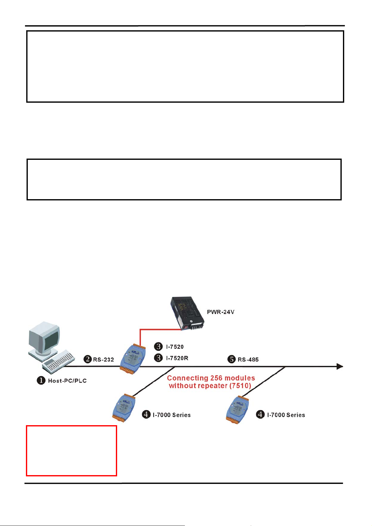
WARNING!! ERROR CONDITION 2: if the p7520 uses the same DC
power ground with nHost PC/PLC (for example, nHost PC/PLC
provide non-isolated DC power source to p7520). In this situation,
(1) The nHost PC/PLC is common ground with power ground of p7520
(2) The power ground of p7520 is common ground with rRS-485
Therefore the nHost PC/PLC is common ground with rRS-485 network.
That is to say, there is no isolation between nHost PC/PLC and rRS-485
network. So the nHost PC/PLC may be damaged if there is high voltage
transient on rRS-485 network.
OK CONDITION: If the DC power ground of p7520 or p7520R is not common
to any module, the nHost PC/PLC will be isolated from rRS-485 network in
all conditions.
The power adapter PWR-24 is designed for single 7000 series modules
only. The 24V DC output of the PWR-24 is isolated from its AC input. If the
p7520 or p7520R is connected to the PWR-24, this PWR-24 cannot connect
to the other module. Normally the nHost PC/PLC uses a switching power and
the DC output of this power supply is also isolated from its AC input. Therefore
the DC power ground of p7520 or p7520R is isolated from nHost PC/PLC.
Therefore, the nHost PC/PLC is isolated from rRS-485 network in all condition.
nHost PC/PLC is isolated
from rRS-485 network
for p7520 or p7520R in
all condition
7000 Bus Converter User’s Manual (Version 1.8 Jan/2006, 7PH-006-18) --------------- 22
Page 23
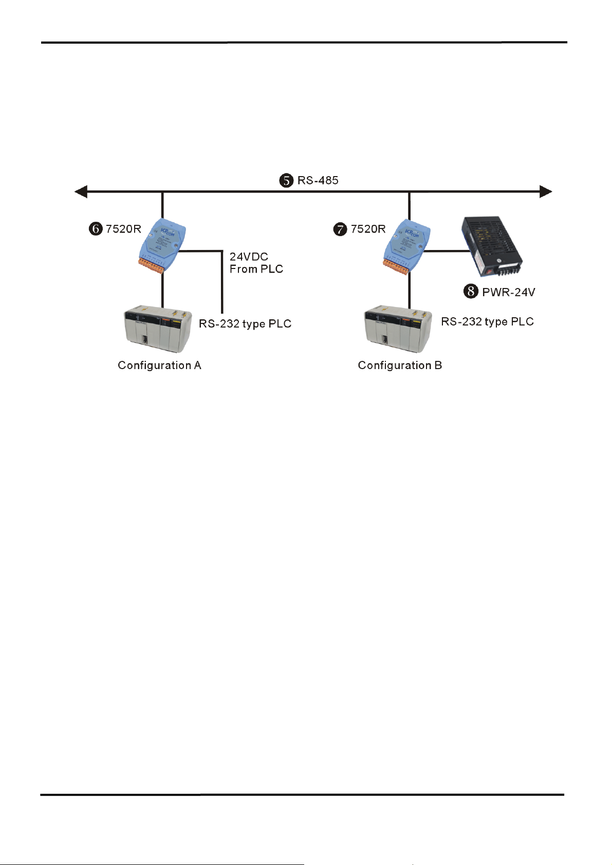
The 7520R is designed for PLC networking. During normal
conditions, the PLC system will have a stable DC-24V power source. The
user may use this power source to s7520R(configuration A). When using
t7520, the user must use another power source, uPWR-24
(configuration B).
The isolation feature is very important in real world applications, therefore
the user should pay attention when selecting the correct module. If the wrong
module is selected, the isolation will be removed but the module will still
function OK. This may cause unexpected damaged by high-energy transients
on an RS-485 network.
7000 Bus Converter User’s Manual (Version 1.8 Jan/2006, 7PH-006-18) --------------- 23
Page 24

3. USB series: I-7560 / I-7561 / I-7563
What is USB?
USB, or Universal Serial Bus is a connectivity specification developed by
computer and telecommunication industry members for attaching
peripherals to computers.
USB is designed to free all the troubles when installing external
peripherals. It eliminates the hassle to open computer case for installing
cards needed for certain devices.
It is designed to meet Microsoft Plug and Play (PnP) specification,
meaning users can install, and hot-swap devices without long installation
procedures and reboots.
The I-756x USB to RS-232 or RS-485 or RS-422 converter are your smart
and convenient accessory for connecting RS-232 serial devices to your
USB-equipped Windows host computer. It provides a bridge connection
with a standard DB 9-pin male serial port connector in one end and a
standard Type-A USB plug connector on the other end. You simply attach
the serial device onto the serial port of the cable and plug the USB
connector into your PC USB port. It allows a simple and easy way of
adding serial connections to your PC without having to go thru inserting a
serial card and traditional port configuration.
This USB to Serial adapter is ideal for connecting modems, cellular
phones, PDAs, digital cameras, card readers and other serial devices to
your computer. It provides serial connections up to 1Mbps of data transfer
rate. And since USB does not require any IRQ resource, more devices
can be attached to the system without the previous hassles of device and
resource conflicts.
Finally, the I-756x USB to Serial adapter is a fully USB Specification
compliant device and therefore supports advanced power management
such as suspend and resume operations as well as remote wakeup. The
I-756x USB Serial products are designed to work on Win98/ME/2000/XP
and Linux operating systems.
7000 Bus Converter User’s Manual (Version 1.8 Jan/2006, 7PH-006-18) --------------- 24
Page 25
3.1 I-7560 Pin Assignment and Specifications:
Introduction
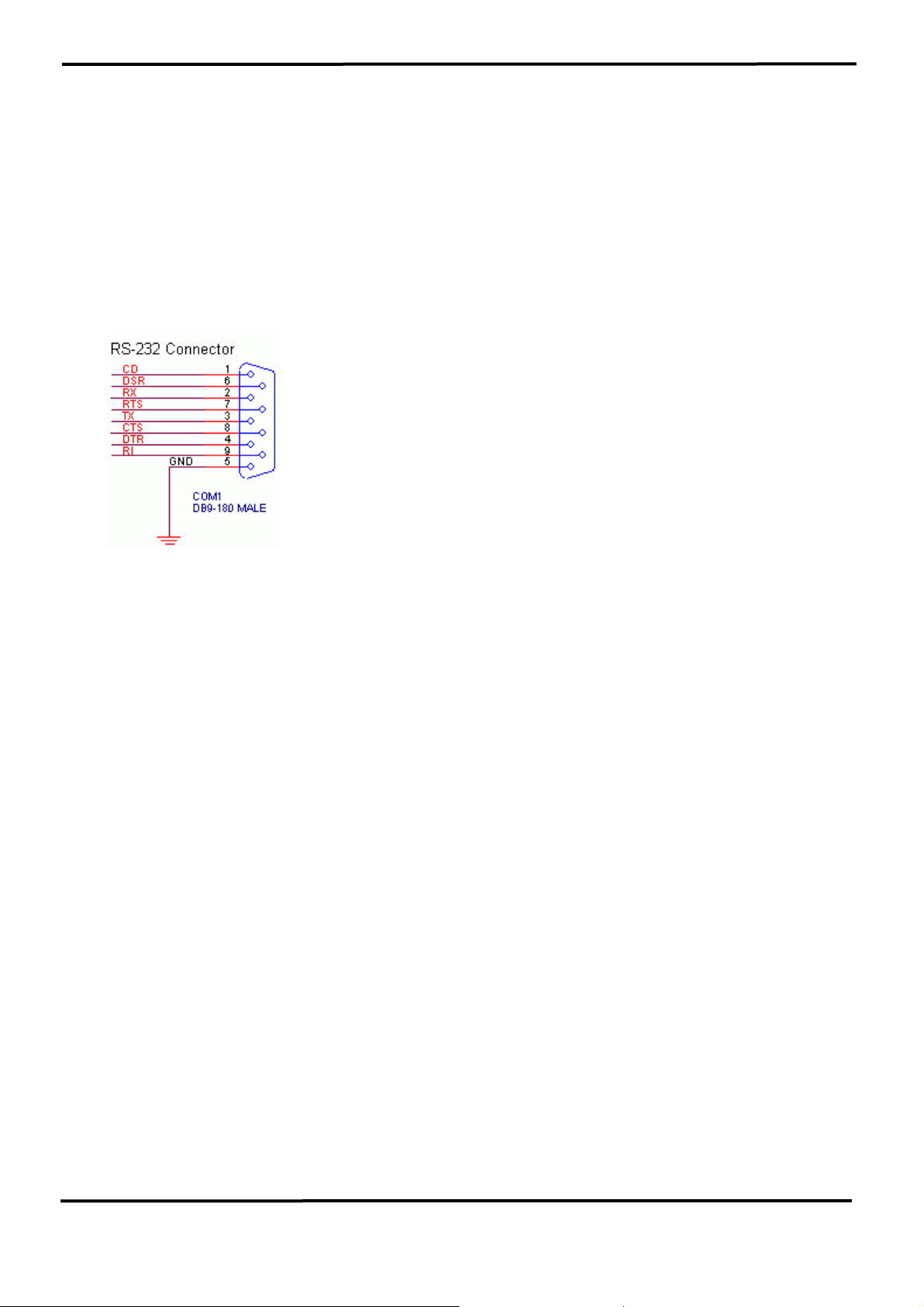
The I-7560 adds a Windows serial Com port via its
USB connection and is compatible with new &
legacy RS-232 devices. USB Plug and Play allows
easy serial port expansion and requires no IRQ,
DMA, or I/O port resources.
I-7560 features a full set of RS-232 modem data and
control signals (TxD, RxD, RTS, CTS, DSR, DTR,
DCD, RI, and GND) on its PC compatible DB9 male
connector. It also features a high-speed 115.2 Kb/s
transmission rate. So you can download program to
I-8000 series, and supports various O.S. No external
power supply is required as I-7560 takes its power
from the USB bus.
I-7560 comes complete with drivers for Microsoft
Windows '98, Windows ME, Windows 2000 and
Windows XP. Drivers are also available for Linux.
Specifications
z Compatibility: USB 1.1 and 2.0 standard
z Input port: USB
z Output port: 9-wire RS-232
z Cable: USB type A connector (Type A to Type B cable provided).
z RS-232 Signals: TxD, RxD, RTS, CTS, DSR, DTR, DCD, RI, and GND
z Power consumption: 1.5 W max.
z Operating temperature: -25℃ to +75℃
z Storage temperature: -25℃ to +80℃
z Humidity: 5~ 95%
z Driver Supported: Windows 98/ME/2000/XP, Linux
7000 Bus Converter User’s Manual (Version 1.8 Jan/2006, 7PH-006-18) --------------- 25
Page 26
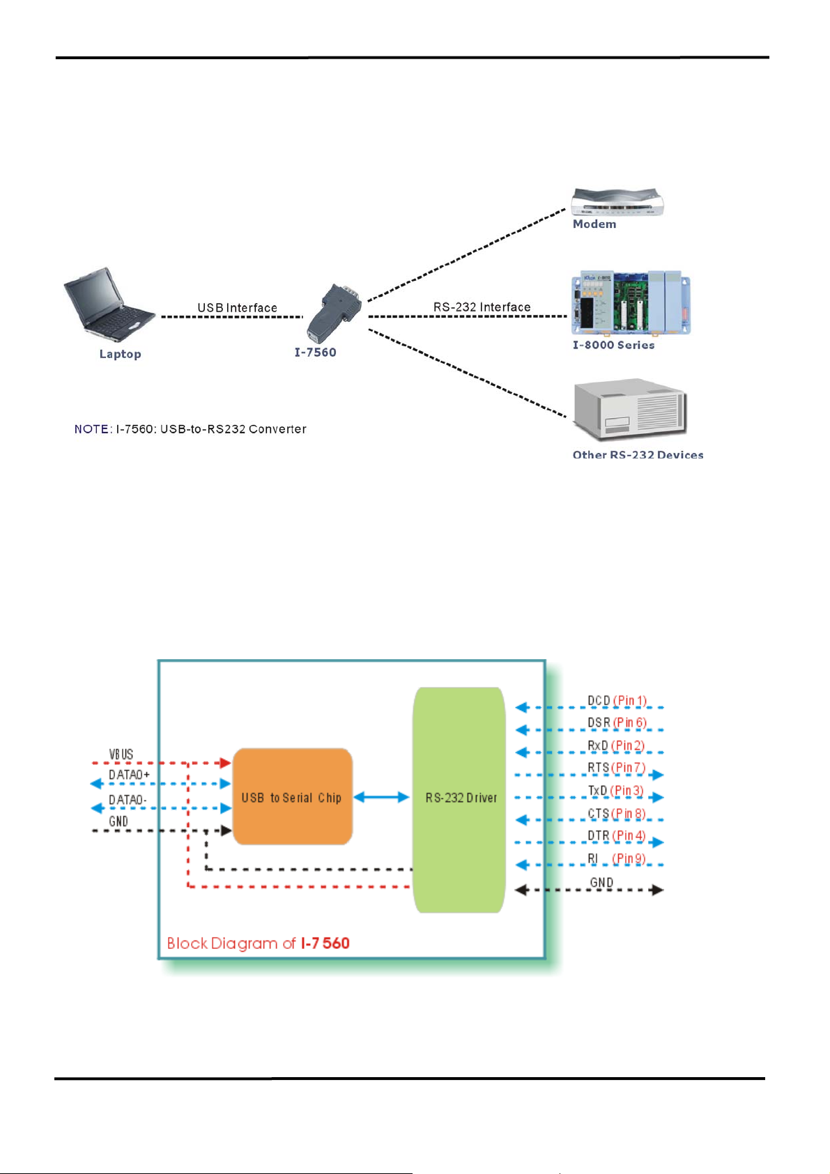
3.1.1 The I-7560 System Network Configuration:
3.1.2 Block Diagram:
7000 Bus Converter User’s Manual (Version 1.8 Jan/2006, 7PH-006-18) --------------- 26
Page 27
3.1.3 I-7560 Driver Installation
Installing the Device
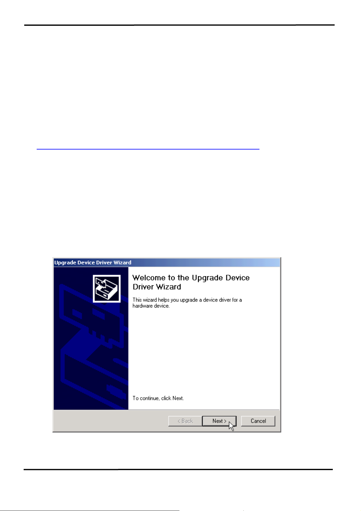
This section will guide you on how to install the I-7560 USB to RS-232
converter under Windows XP, Windows 2000, Windows ME, and
Windows 98 operating systems. (No support for WinNT). Download driver
files from
1. Package CD, \Napdos\7000\756x\7560
ftp://ftp.icpdas.com/pub/cd/8000cd/napdos/7000/756x/7560
2.
The following steps will show how to install the device under Windows
2000. Basically, the procedures are also somewhat the same for other
Windows operating systems.
1. Power on your computer and boot to Windows.
2. Locate the USB port of your computer and plug in the I-7560.
3. Windows will detect the new device and will initiate the Found New
Hardware Wizard prompting you to install the software for the detected
USB Device. Select to install from a list or specific location. Click Next
to continue.
7000 Bus Converter User’s Manual (Version 1.8 Jan/2006, 7PH-006-18) --------------- 27
Page 28
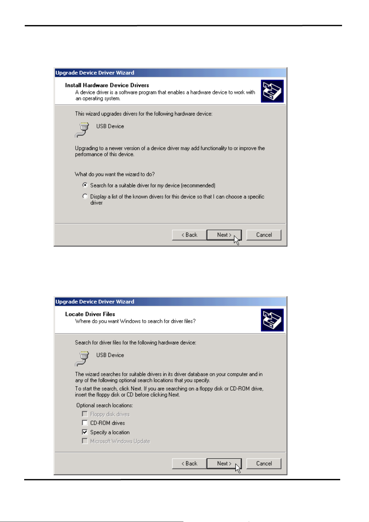
4. An “Install Hardware Device Drivers” window is shown. Click “Next” to
initiate a search for a suitable driver for your device.
5. Select the “Specify a location” optional search locations. If the
“CD-ROM drives” checkbox is selected, please insert the driver CD.
Click “Next” to start the search.
7000 Bus Converter User’s Manual (Version 1.8 Jan/2006, 7PH-006-18) --------------- 28
Page 29
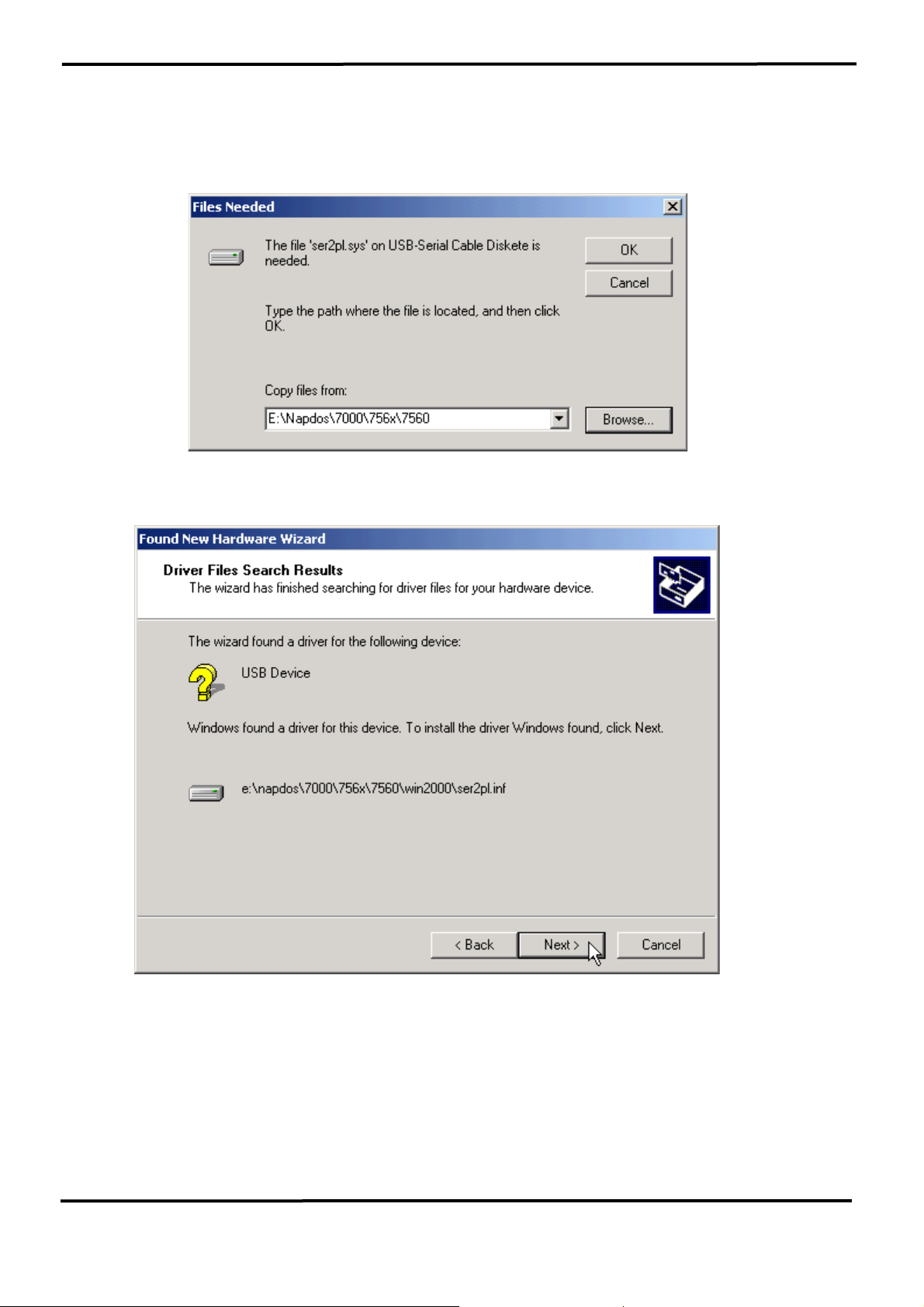
6. If the “Specify a location” is selected, you much choose the correct
path. Enter E:\Napdos\7000\756x\7560(The ‘E’ is the Disk that
Package CD put in). Click “OK” to start the search.
7. Once Windows finds the correct driver, click “Next” to install the driver.
7000 Bus Converter User’s Manual (Version 1.8 Jan/2006, 7PH-006-18) --------------- 29
Page 30
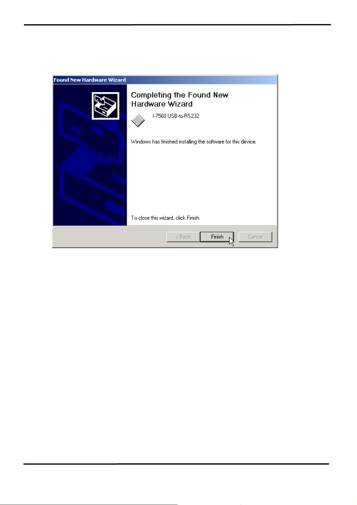
8. Windows will then install the driver for the USB-to-Serial COM Port.
Once installation is complete, Windows will notify you that it has
finished installing the software. Click “Finish” to continue.
NOTE: When you finish the driver installation, please unplug the USB
cable, and then plug the USB cable again.
7000 Bus Converter User’s Manual (Version 1.8 Jan/2006, 7PH-006-18) --------------- 30
Page 31
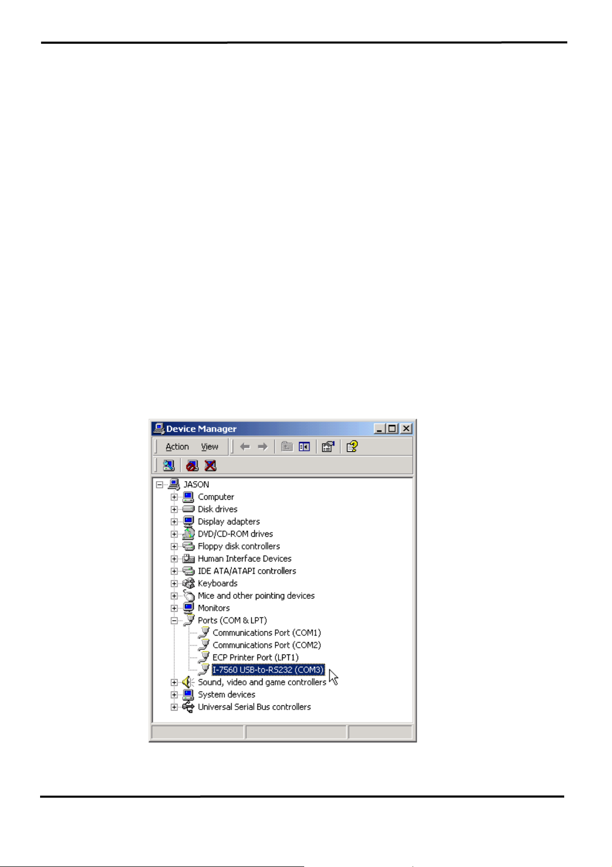
3.1.4 Verifying the Installation:
This section will show you on how to verify whether the I-7560 was
properly installed. You will also need to determine the COM port
assignment made by Windows for the USB to RS-232 converter.
Note: Before you connect the I-7560 for the first time, ensure that you do
not attach any serial devices to the converter. You must only connect the
I-7560 itself.
To verify whether the device is properly installed and determine the COM
port assignment for the device:
1. Click “Start” Æ “Settings” Æ “Control Panel”, then double click on the
“System” icon. Once the System Properties window is display, click on
” Hardware” tab and then click on the “Device Manager” button. Double-
click on Ports (COM & LPT). If the device was correctly installed, you
should now see the I-7560 USB-to-RS232 (COM3) device listing. This
also means that Windows has assigned the device to the COM3 port.
7000 Bus Converter User’s Manual (Version 1.8 Jan/2006, 7PH-006-18) --------------- 31
Page 32
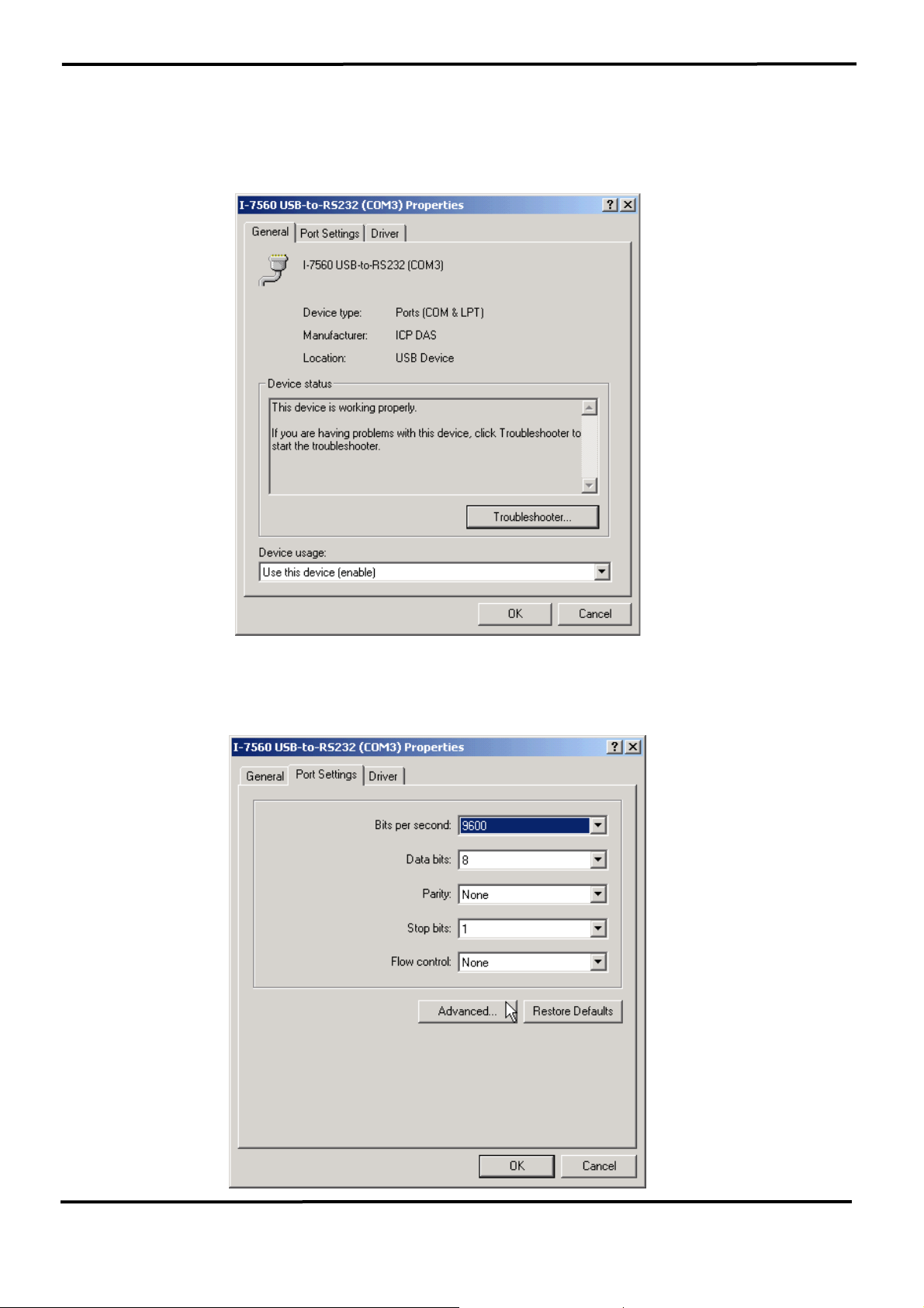
2. If you need to reassign the COM Port name to another Port number,
you can double-click on the device (I-7560 USB-to-RS232) to view the
properties. (The I-7561 cannot reassign the COM Port name to another
Port number under Win98 and Win98SE.)
3. Once the properties window opens click on the Port Settings tab. Then
click on the advanced button.
7000 Bus Converter User’s Manual (Version 1.8 Jan/2006, 7PH-006-18) --------------- 32
Page 33
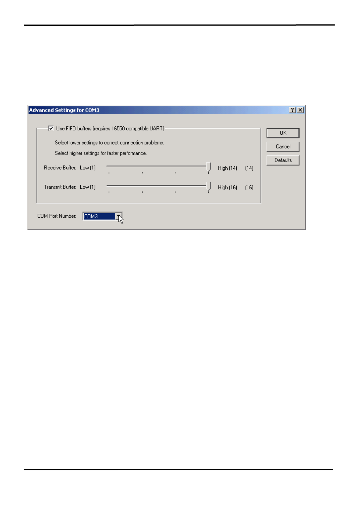
4. The Advanced Settings dialog box will now be displayed. Click on the
COM Port Number drop down box to check what other port numbers are
available. If, for instance, Windows has assigned COM5 to the device, you
may try to reassign it to a lower unused port number. Click OK when
finished. Try running HyperTerminal to test whether the new port number
is OK.
Note: Some software programs may only support Ports up to COM4 and
may not work if the port is assigned to COM5 or higher.
5. Once you have verified that the device has been properly installed, you
may now proceed to use the USB-to-RS232 Converter to connect to serial
devices. Attach the serial device to the serial port of the adapter and then
connect the USB connector to the USB port of your computer. Use the
supplied driver for the serial device if needed.
7000 Bus Converter User’s Manual (Version 1.8 Jan/2006, 7PH-006-18) --------------- 33
Page 34
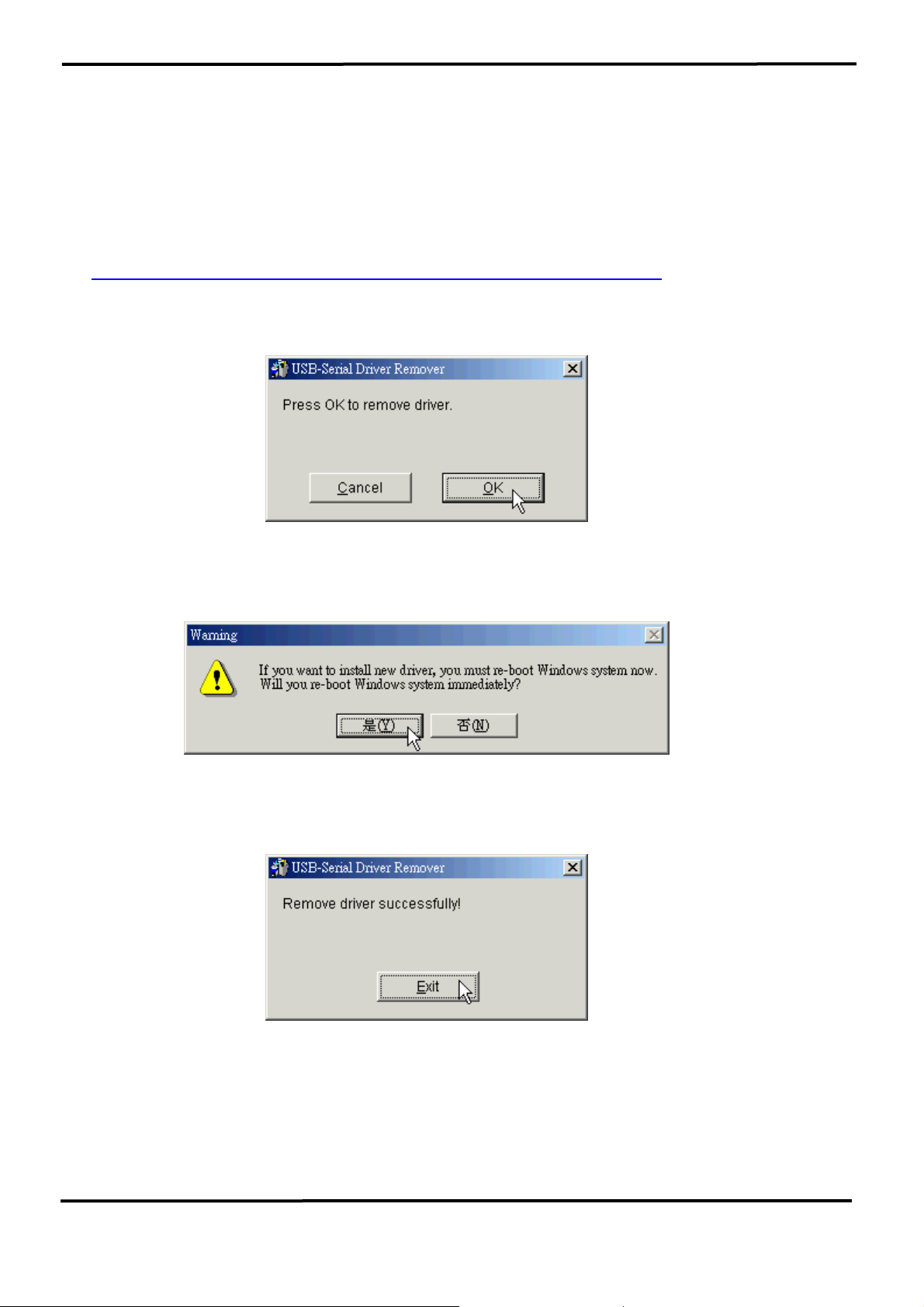
3.1.5 Uninstalling the Device Driver
It is easy to uninstall the USB to Serial device driver:
1. Run the DRemover98_2K.exe Uninstall program which can be found on
the Package CD, \Napdos\7000\756x\7560 or at
ftp://ftp.icpdas.com/pub/cd/8000cd/napdos/7000/756x/7560
2. The uninstall program will then prompt you whether you want to remove
the utility program. Click “ OK “ to continue.
3. After the uninstall is complete, the program will prompt you to restart
Windows. Click “ Yes ” to continue.
4. Windows will show a dialog box to notify you that the driver was
removed successfully. Wait for Windows to restart your computer.
7000 Bus Converter User’s Manual (Version 1.8 Jan/2006, 7PH-006-18) --------------- 34
Page 35
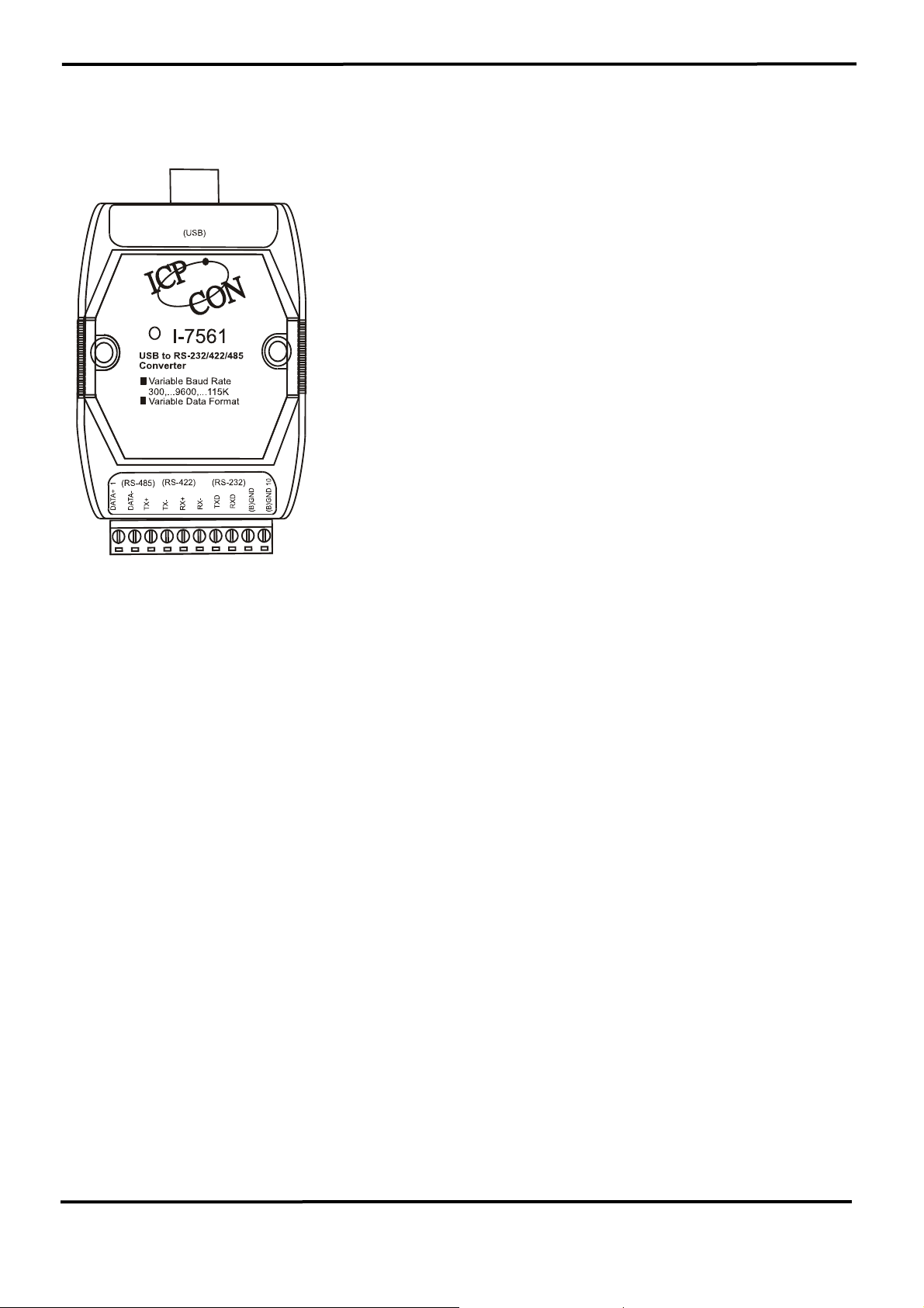
3.2 I-7561 Pin Assignment and Specifications
Introduction
The I-7561 is a cost-effective module for transfer
serial data over USB. It allows you to connect your
serial devices to systems using a USB interface.
Connecting the I-7561 to a PC, you get one extra
high-speed RS-232/422/485 ports. Like our I-7520A,
the I-7561 contains “ Self Tuner “ This chip auto-tunes
the baud rate and data format to the RS-485 network.
The I-7561 module derives the power from the USB
port and doesn’t need any power adapter (when you
use I-7561, you should connect power ground to other
modules). It also features a high-speed 115.2 Kb/s
transmission rate, and supports various O.S.
independent RS-232/422/485 Ports.
Specifications
z Compatibility: USB 1.1 and 2.0 standard
z Input Port: USB.
z Cable: USB type “A” connector (Type “A” to type “B” cable provided).
z Output Port: 3-wire RS-232, RS-422, RS-485
z Speed: “Self Tuner” inside
z 3000 V DC Isolation protections provided.
z Photo-coupler isolation: 2500V rms
z 256 modules max. In one RS-485 network without repeater.
z Repeater request: 4,000 feet or over 256 modules.
z Parity Bit : odd, even, none
z Data Bit : 5,6,7,8
z Stop Bit :1, 1.5, 2
z Power requirements: Voltage support by USB interface of the Host-PC
z Operating temperature: -25℃ to +75℃
z Storage temperature: -25℃ to +80℃
z Humidity: 5~ 95%
z Driver Supported: Windows 98/ME/2000/XP, Linux
7000 Bus Converter User’s Manual (Version 1.8 Jan/2006, 7PH-006-18) --------------- 35
Page 36
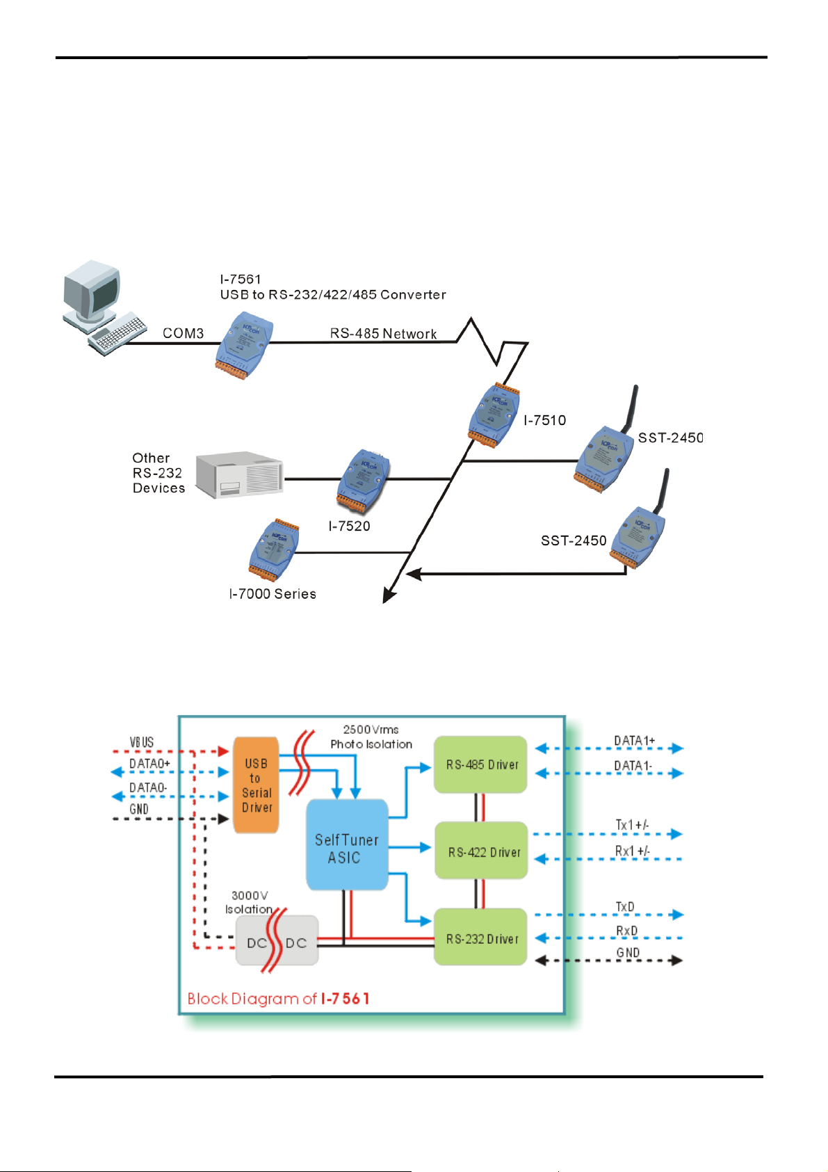
3.2.1 The I-7561 System Network Configuration:
• Multiple Baud Rate
• Multiple Data Format
3.2.2 The I-7561 Block Diagram:
7000 Bus Converter User’s Manual (Version 1.8 Jan/2006, 7PH-006-18) --------------- 36
Page 37

3.2.3 I-7561 has four different output types.
Selecting the I-7561 output type.
NOTE: The RS-232, RS-422 and RS-485 output types couldn’t be used
simultaneously, which means that you can only select 1 type to output.
Type 1: 1-channel RS-485 output.
Type 2: 1-channel RS-422 output.
Type 3: 2-channel RS-485 output. (Support star network)
Type 4: 1-channel RS-232 output.
RS422/485 Output Jumpers settings:
For type 1: Set the JP3 jumper to positions 2 and 3.
For type 2: Set the JP3 jumper to positions 2 and 3.
For type 3: Set the JP3 jumper to positions 1 and 2.
For type 4: Set the JP3 jumper to positions 2 and 3.
You don’t need “PLUG AND PLAY”, when you finish the Jumper setting.
JP3
1
2
3
Types 1 and 2:
Default setting
RS-422 or RS-485
JP3
Pin Assignment For type1 and type2:
1
Type 3:
2
2-channel RS-485
3
RS-485 Pin define:
DATA+ and DATA-
RS-422 Pin define:
TX+, TX-, RX+ and RX-
Pin Assignment For type3:
Channel one Pin define:
DATA1+ and DATA1-
Channel two Pin define:
DATA2+ and DATA2-
7000 Bus Converter User’s Manual (Version 1.8 Jan/2006, 7PH-006-18) --------------- 37
Page 38
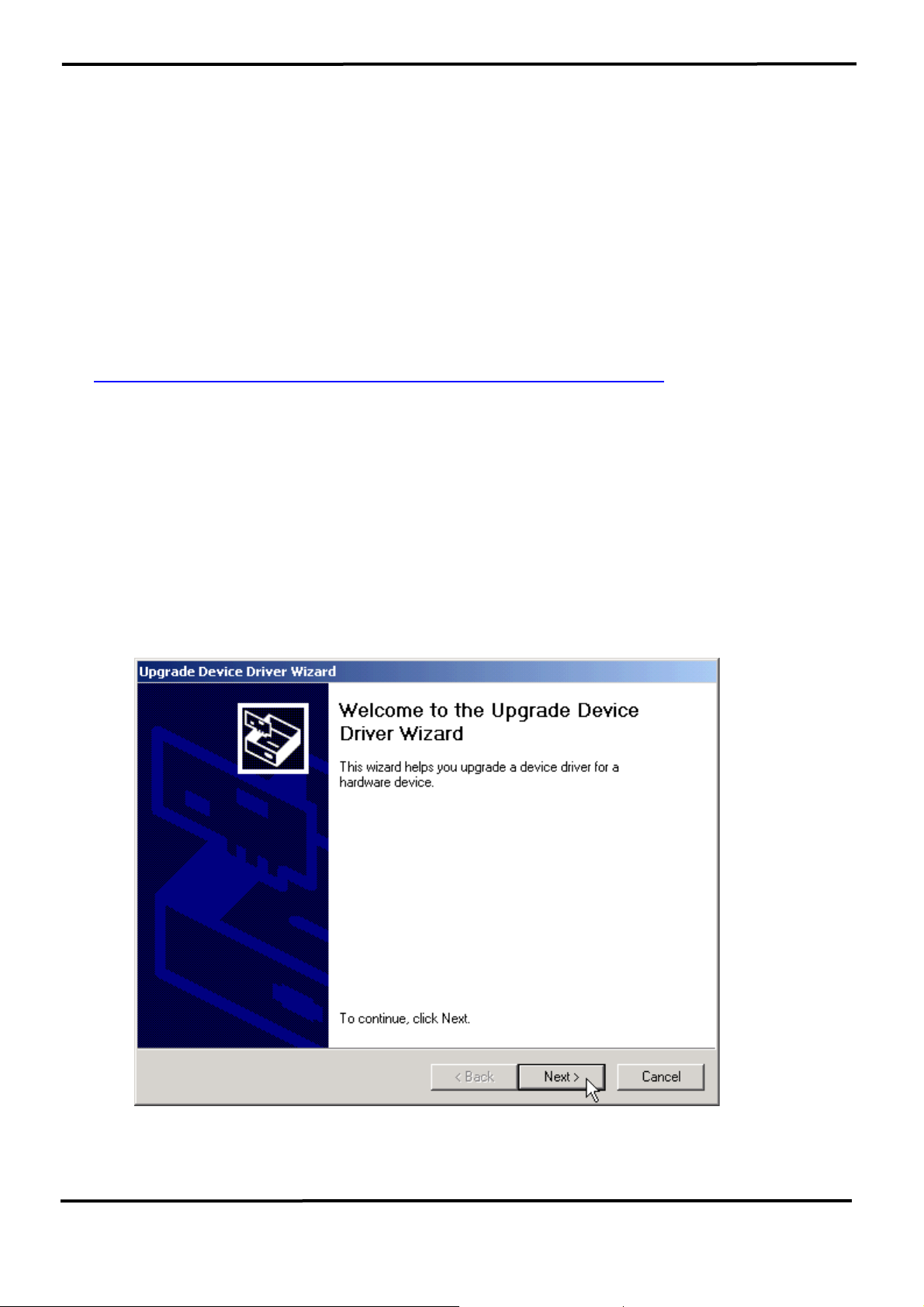
3.2.4 I-7561 Driver Installation
Installing the Device
This section will guide you on how to install the I-7561 USB to
RS-232/422/485 converter under Windows XP, Windows 2000, Windows
ME, and Windows 98 operating systems. (No support for WinNT).
Download driver files from
1. Package CD, \Napdos\7000\756x\7561
ftp://ftp.icpdas.com/pub/cd/8000cd/napdos/7000/756x/7561
2.
The following steps will show how to install the device under Windows
2000. Basically, the procedures are also somewhat the same for other
Windows operating systems.
1. Power on your computer and boot to Windows.
2. Locate the USB port of your computer and plug in the I-7561.
3. Windows will detect the new device and will initiate the Found New
Hardware Wizard prompting you to install the software for the detected
USB Device. Select to install from a list or specific location. Click Next
to continue.
7000 Bus Converter User’s Manual (Version 1.8 Jan/2006, 7PH-006-18) --------------- 38
Page 39
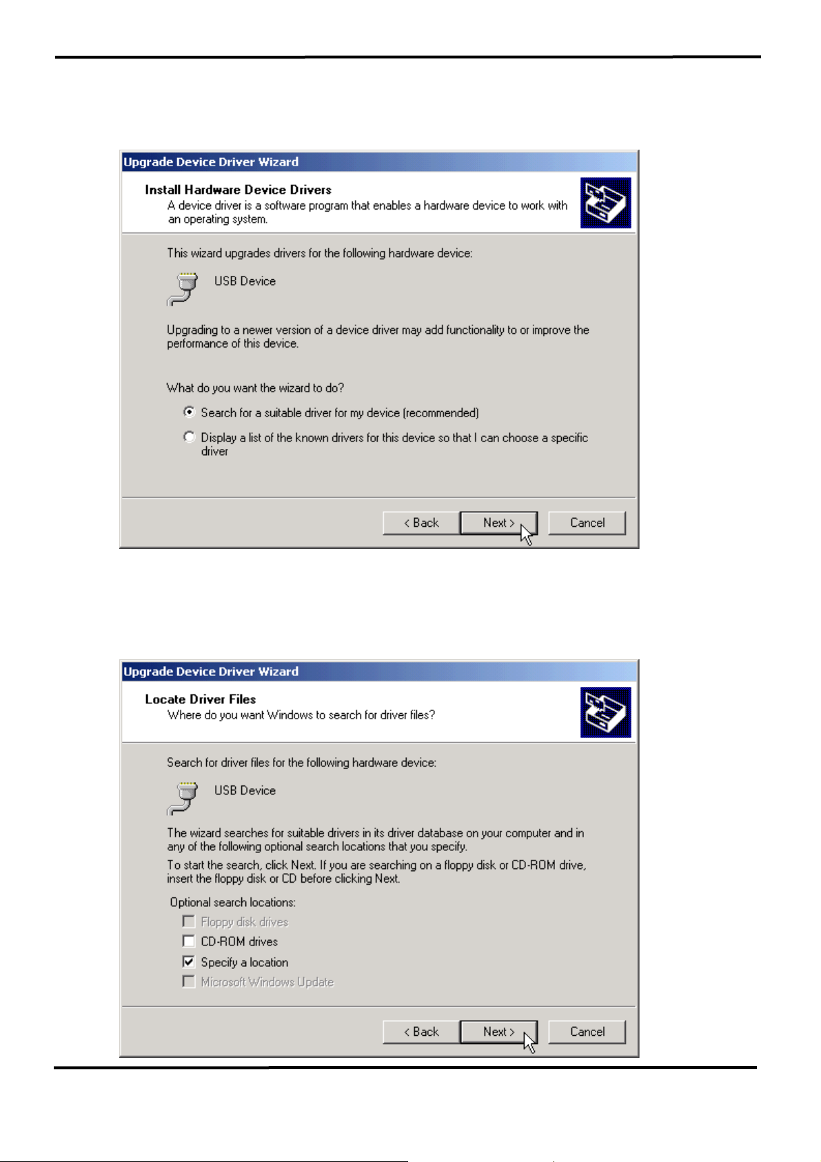
4. An “Install Hardware Device Drivers” window is shown. Click “Next” to
initiate a search for a suitable driver for your device.
5. Select the “Specify a location” optional search locations. If the
“CD-ROM drives” checkbox is selected, please insert the driver CD.
Click “Next” to start the search.
7000 Bus Converter User’s Manual (Version 1.8 Jan/2006, 7PH-006-18) --------------- 39
Page 40
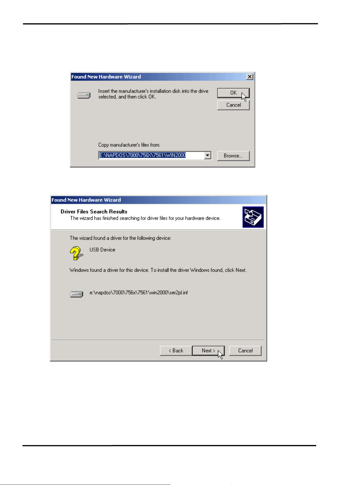
6. If the “Specify a location” is selected, you much choose the correct
path. Enter E:\Napdos\7000\756x\7561(The ‘E’ is the Disk that
Package CD put in). Click “OK” to start the search.
7. Once Windows finds the correct driver, click “Next” to install the driver.
7000 Bus Converter User’s Manual (Version 1.8 Jan/2006, 7PH-006-18) --------------- 40
Page 41
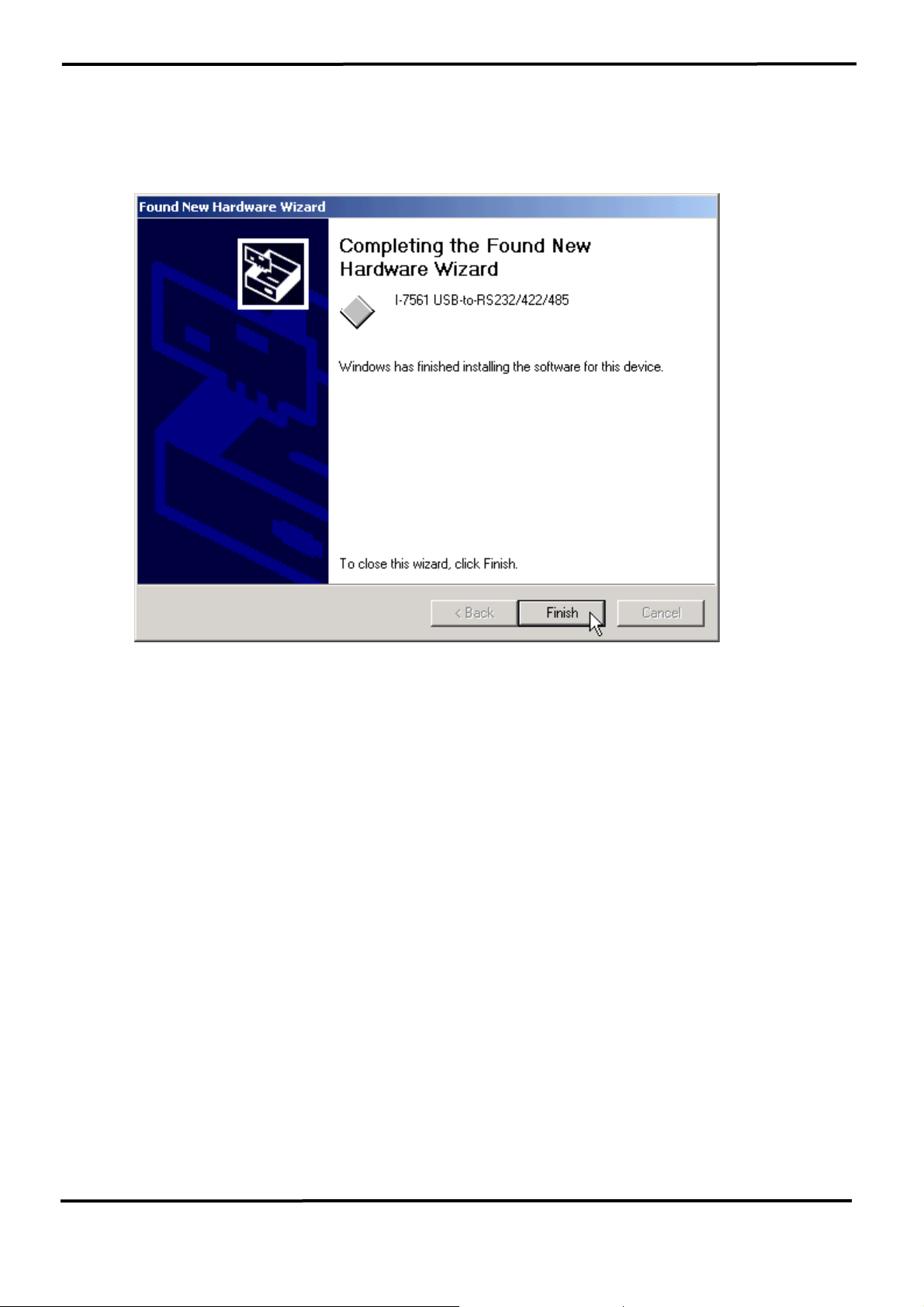
8. Windows will then install the driver for the USB-to-RS232/422/485.
Once installation is complete, Windows will notify you that it has
finished installing the software. Click “Finish” to continue.
NOTE: When you finish the driver installation, please unplug the USB
cable, and then plug the USB cable again.
7000 Bus Converter User’s Manual (Version 1.8 Jan/2006, 7PH-006-18) --------------- 41
Page 42
3.2.5 Verifying the Installation:
This section will show you on how to verify whether the I-7561 was
properly installed. You will also need to determine the COM port
assignment made by Windows for the USB to RS-232/422/485 converter.
Note: Before you connect the I-7561 for the first time, ensure that you do
not attach any serial devices to the converter. You must only connect the
I-7561 itself.
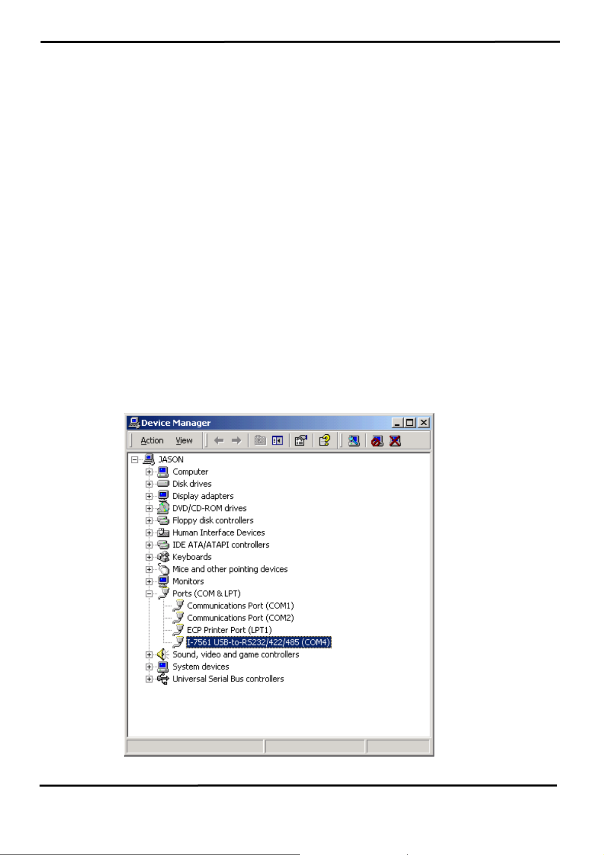
To verify whether the device is properly installed and determine the COM
port assignment for the device:
1. Click “Start” Æ “Settings” Æ “Control Panel”, then double click on the
“System” icon. Once the System Properties window is display, click on
”Hardware” tab and then click on the “Device Manager” button. Double-
click on Ports (COM & LPT). If the device was correctly installed, you
should now see the I-7561 USB-to-RS232/422/485 (COM4) device
listing. This also means that Windows has assigned the device to the
COM4 port.
7000 Bus Converter User’s Manual (Version 1.8 Jan/2006, 7PH-006-18) --------------- 42
Page 43
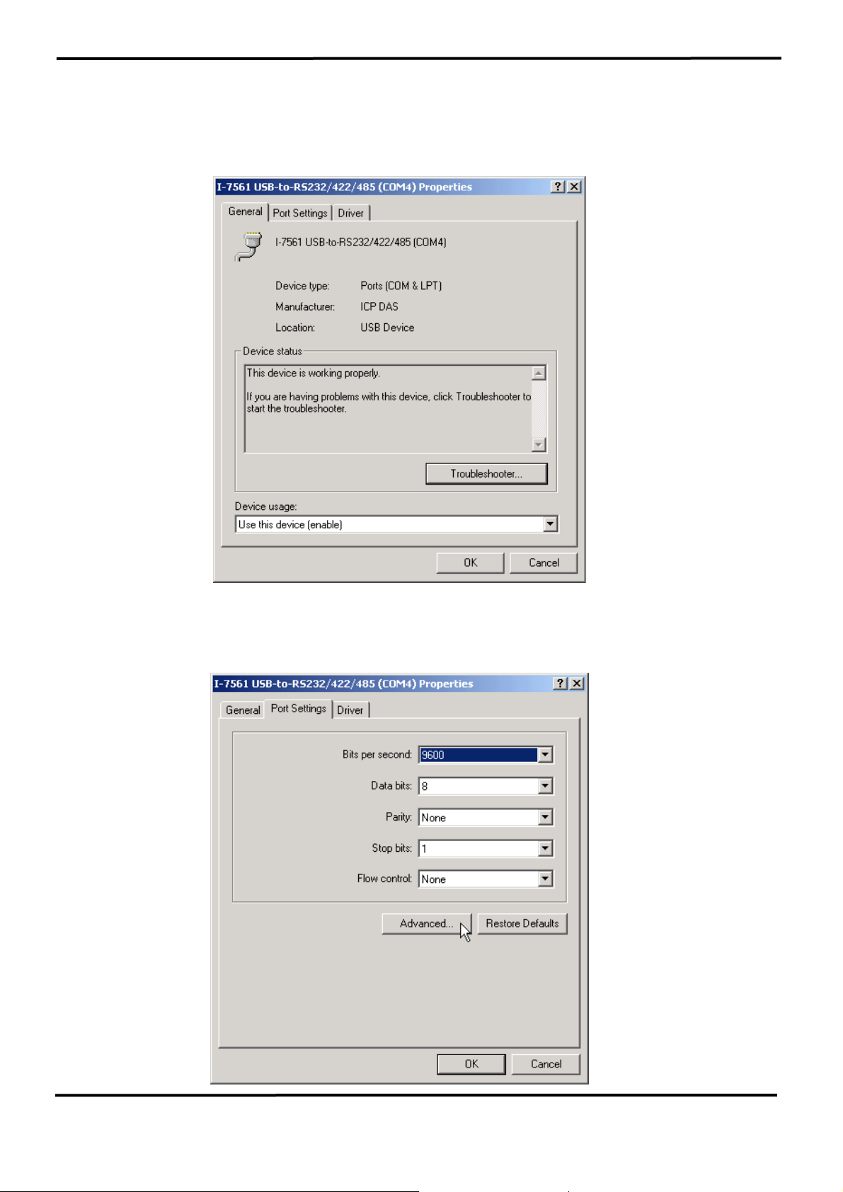
2. If you need to reassign the COM Port name to another Port number,
you can double-click on the device (I-7561 USB-to-RS232/422/485) to
view the properties.
(The I-7561 cannot reassign the COM Port name to
another Port number under Win98 and Win98SE.)
3. Once the properties window opens click on the Port Settings tab. Then
click on the advanced button.
7000 Bus Converter User’s Manual (Version 1.8 Jan/2006, 7PH-006-18) --------------- 43
Page 44
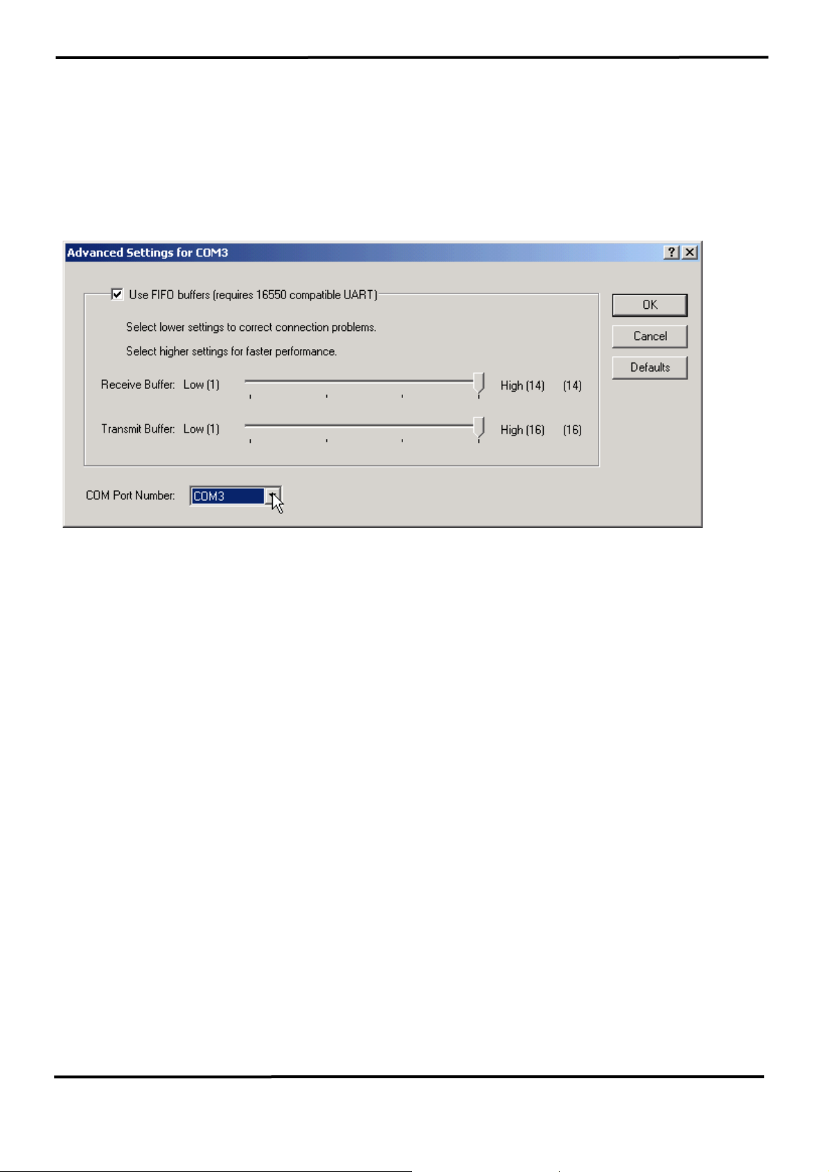
4. The Advanced Settings dialog box will now be displayed. Click on the
COM Port Number drop down box to check what other port numbers are
available. If, for instance, Windows has assigned COM5 to the device, you
may try to reassign it to a lower unused port number. Click OK when
finished. Try running HyperTerminal to test whether the new port number
is OK.
Note: Some software programs may only support Ports up to COM4 and
may not work if the port is assigned to COM5 or higher.
5. Once you have verified that the device has been properly installed, you
may now proceed to use the USB-to-RS232/422/485 Converter to
connect to serial devices. Attach the serial device to the serial port of the
adapter and then connect the USB connector to the USB port of your
computer. Use the supplied driver for the serial device if needed.
7000 Bus Converter User’s Manual (Version 1.8 Jan/2006, 7PH-006-18) --------------- 44
Page 45
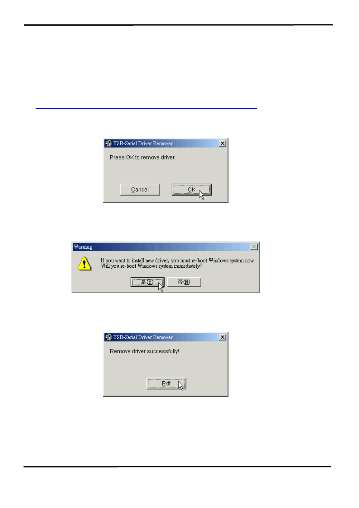
3.2.6 Uninstalling the Device Driver
It is easy to uninstall the USB to Serial device driver:
1. Run the DRemover98_2K.exe Uninstall program which can be found on
the Package CD, \Napdos\7000\756x\7561 or at
ftp://ftp.icpdas.com/pub/cd/8000cd/napdos/7000/756x/7561
2. The uninstall program will then prompt you whether you want to remove
the utility program. Click OK to continue.
3. After the uninstall is complete, the program will prompt you to restart
Windows. Click “Yes” to continue.
4. Windows will show a dialog box to notify you that the driver was
removed successfully. Wait for Windows to restart your computer.
7000 Bus Converter User’s Manual (Version 1.8 Jan/2006, 7PH-006-18) --------------- 45
Page 46
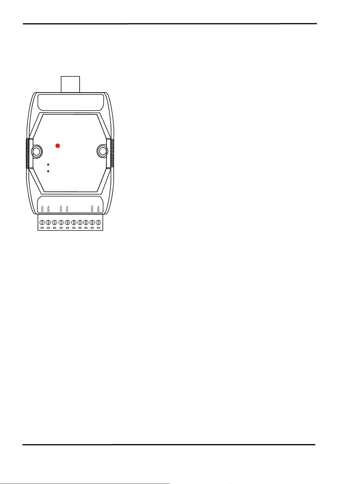
3.3 I-7563 Pin Assignment and Specifications:
Introduction
( USB )
The I-7563 is a cost-effective module for transfer
serial data over USB. It allows you to connect
your serial devices to systems using a USB
interface. Connecting the I-7563 to a PC, The I-
7563 contains “ Self Tuner “ This chip auto-tunes
I-7563
USB to 3 Ports RS-485 Hub
Converter
Variable Baud Rate
300,..9600,..115.2K
Variable Rate Format
the baud rate and data format to the Rs-485
network. The I-7563 module derives the power
from the USB port and doesn’t need any power
adapter. It also features a high-speed 115.2 Kb/s
transmission rate, and supports various O.S.
( CH 3 )
( CH 2 )
( CH 1 )
I-7563 is a USB to one channel RS-485
converter with a three way RS-485 Hub. Each
channel has its own RS-485 driver IC on it, so it
can support star-shaped wiring.
Specifications
z Compatibility: USB 1.1 and 2.0 standard
z Input Port: USB.
z Output Port: Three RS-485.
z Speed: “Self Tuner” inside
z 3000 V DC Isolation protections provided.
z Photo-coupler isolation: 2500V rms
z 256 modules max. In three channels
RS-485 network without repeater.
z 2048 modules max. In three channels
RS-485 network with repeater.
z Repeater request: 4,000 feet or over 256 modules.
z Parity Bit : odd, even, none
z Data Bit : 5,6,7,8
z Stop Bit :1, 1.5, 2
z Operating temperature: -25℃ to +75℃
z Storage temperature: -25℃ to +80℃
z Humidity: 5~ 95%
z Driver Supported: Windows 98/ME/2000/XP, Linux
7000 Bus Converter User’s Manual (Version 1.8 Jan/2006, 7PH-006-18) --------------- 46
Page 47
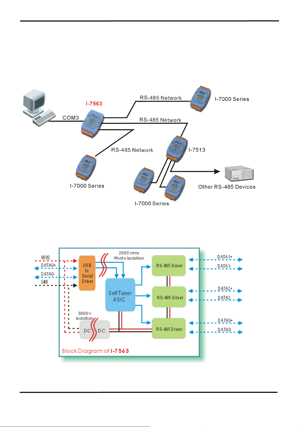
3.3.1 The I-7563 System Network Configuration:
• Multiple Baud Rate
• Multiple Data Format
3.3.2 The I-7563 Block Diagram:
7000 Bus Converter User’s Manual (Version 1.8 Jan/2006, 7PH-006-18) --------------- 47
Page 48
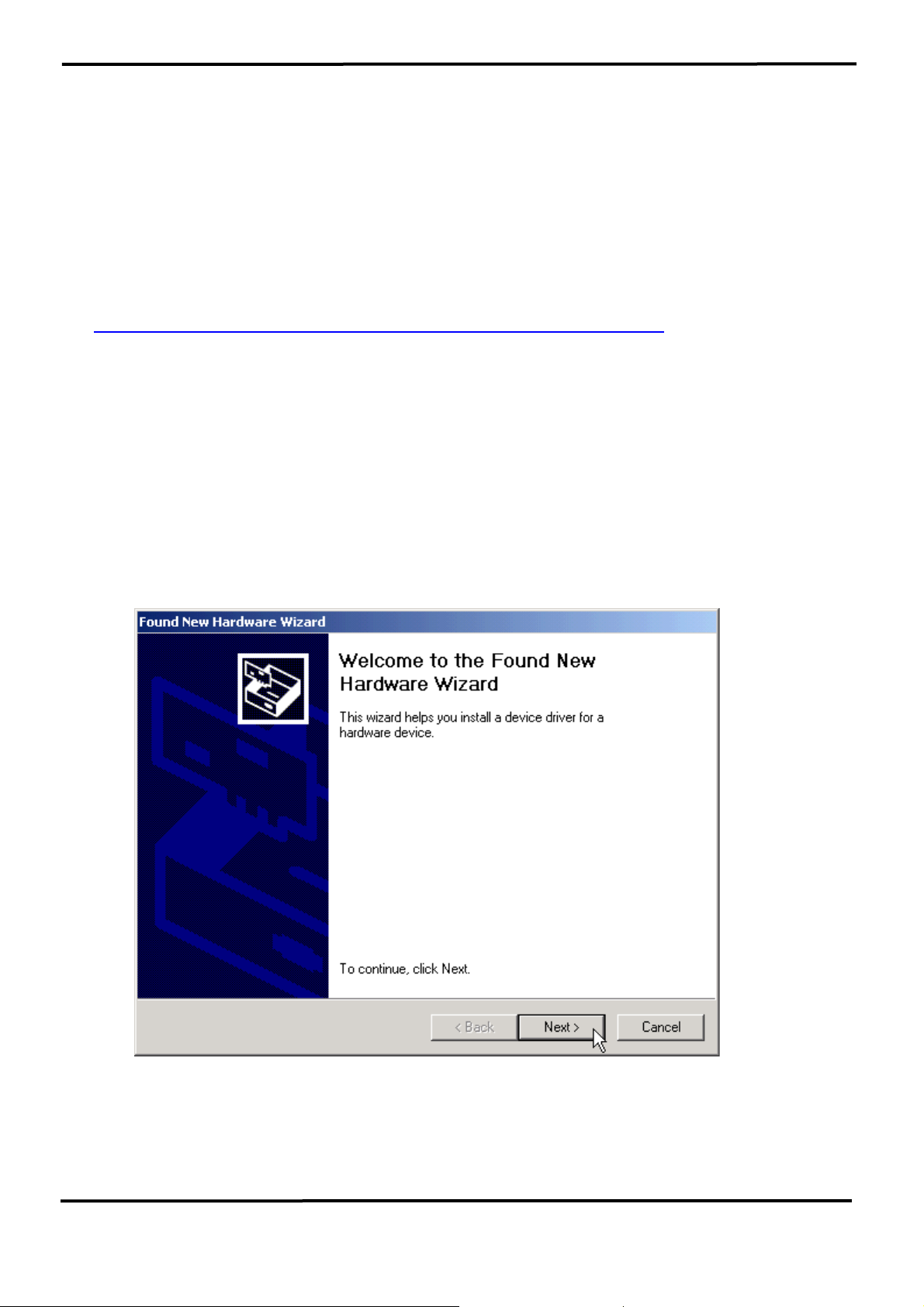
3.3.3 I-7563 Driver Installation
This section will guide you on how to install the I-7563 USB to 3 Ports
RS-485 Hub under Windows XP, Windows 2000, Windows ME, and
Windows 98 operating systems. (No support for WinNT). Download driver
files from
1. Package CD, \Napdos\7000\756x\7563
2. ftp://ftp.icpdas.com/pub/cd/8000cd/napdos/7000/756x/7563
The following steps will show how to install the device under Windows
2000. Basically, the procedures are also somewhat the same for other
Windows operating systems.
1. Power on your computer and boot to Windows.
2. Locate the USB port of your computer and plug in the I-7563.
3. Windows will detect the new device and will initiate the Found New
Hardware Wizard prompting you to install the software for the detected
USB Device. Select to install from a list or specific location. Click Next
to continue.
7000 Bus Converter User’s Manual (Version 1.8 Jan/2006, 7PH-006-18) --------------- 48
Page 49
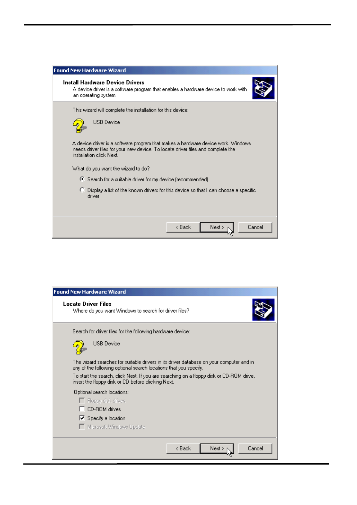
4. An “Install Hardware Device Drivers” window is shown. Click “Next” to
initiate a search for a suitable driver for your device.
5. Select the “Specify a location” optional search locations. If the
“CD-ROM drives” checkbox is selected, please insert the driver CD.
Click “Next” to start the search.
7000 Bus Converter User’s Manual (Version 1.8 Jan/2006, 7PH-006-18) --------------- 49
Page 50
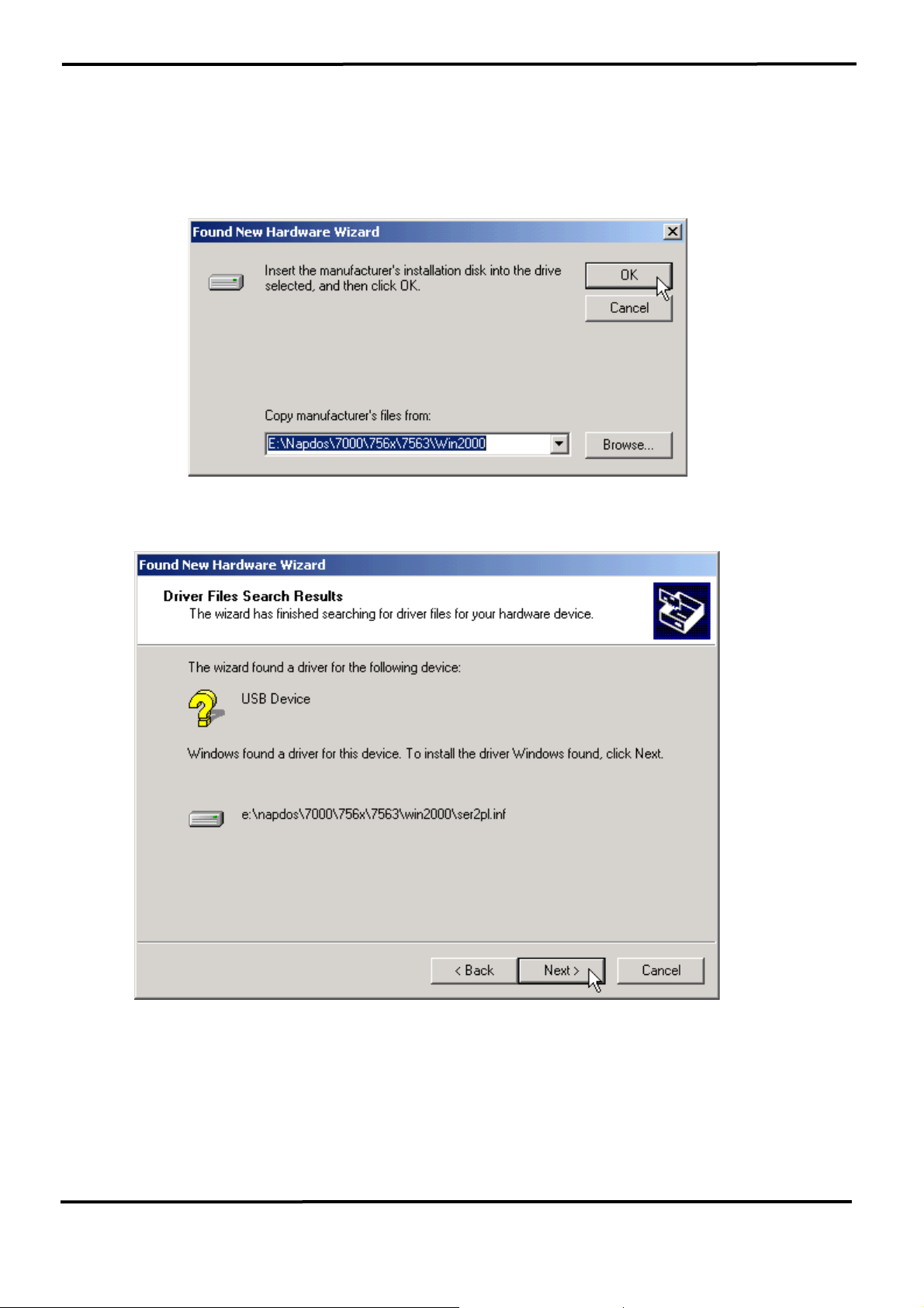
6. If the “Specify a location” is selected, you much choose the correct
path. Enter E:\Napdos\7000\756x\7563(The ‘E’ is the Disk that
Package CD put in). Click “OK” to start the search.
7. Once Windows finds the correct driver, click “Next” to install the driver.
7000 Bus Converter User’s Manual (Version 1.8 Jan/2006, 7PH-006-18) --------------- 50
Page 51
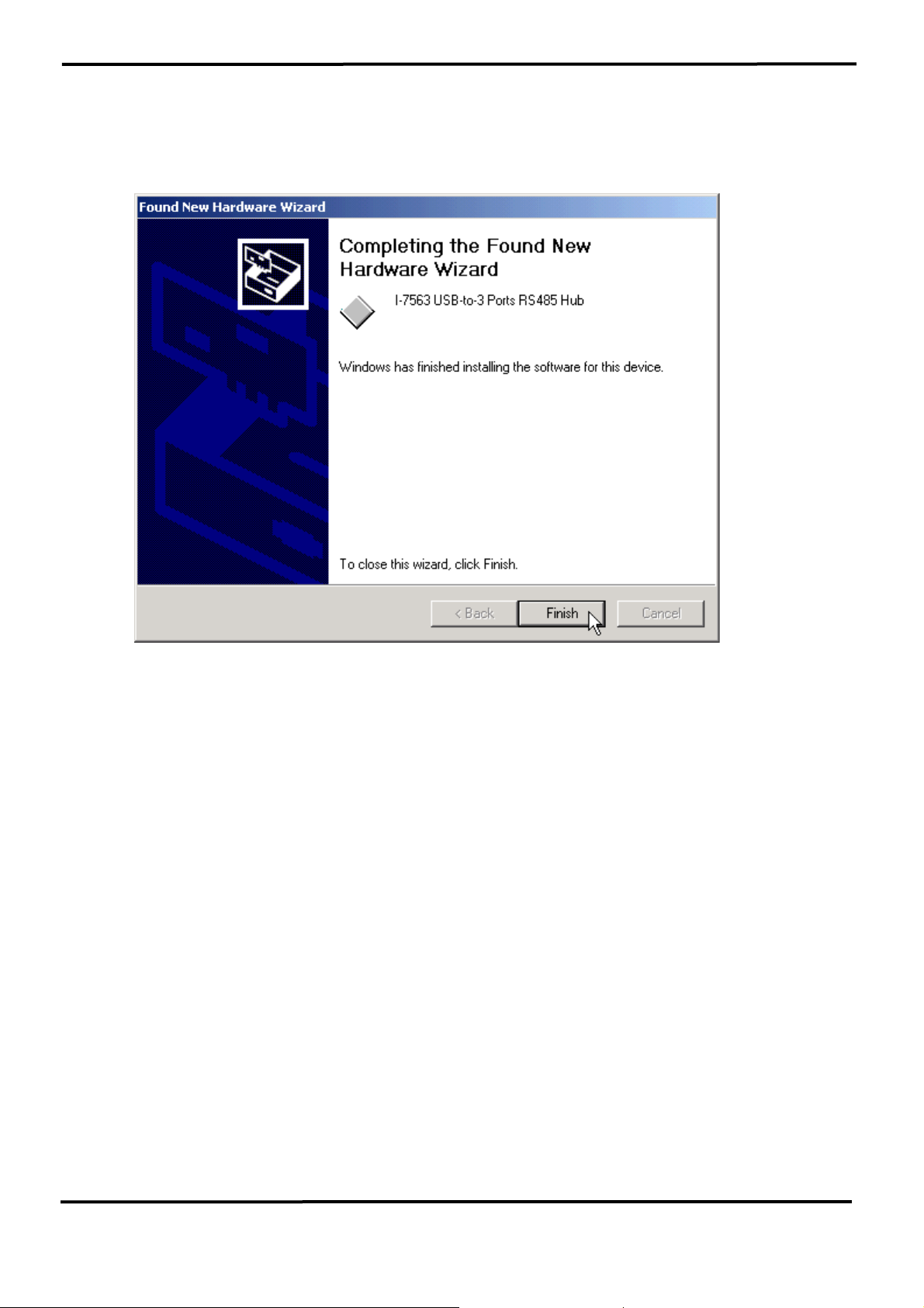
8. Windows will then install the driver for the USB-to-3 Ports. Once
installation is complete, Windows will notify you that it has finished
installing the software. Click “Finish” to continue.
NOTE: When you finish the driver installation, please unplug the USB
cable, and then plug the USB cable again.
7000 Bus Converter User’s Manual (Version 1.8 Jan/2006, 7PH-006-18) --------------- 51
Page 52
3.3.4 Verifying the Installation:
This section will show you on how to verify whether the I-7563 was
properly installed. You will also need to determine the COM port
assignment made by Windows for the USB to 3 Ports RS-485 Hub.
Note: Before you connect the I-7563 for the first time, ensure that you do
not attach any serial devices to the converter. You must only connect the
I-7560.
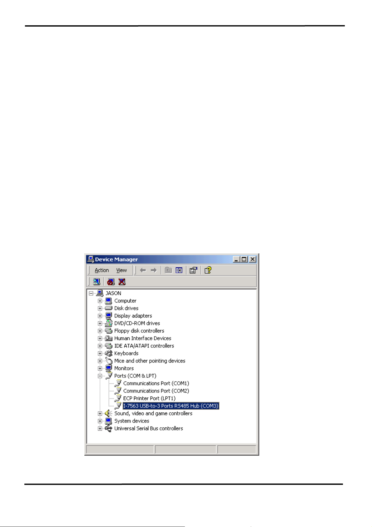
To verify whether the device is properly installed and determine the COM
port assignment for the device:
1. Click “Start” Æ “Settings” Æ “Control Panel”, then double click on the
“System” icon. Once the System Properties window is display, click on
” Hardware” tab and then click on the “Device Manager” button. Double-
click on Ports (COM & LPT). If the device was correctly installed, you
should now see the I-7563 USB-to-3 Ports RS485 Hub (COM3) device
listing. This also means that Windows has assigned the device to the
COM3 port.
7000 Bus Converter User’s Manual (Version 1.8 Jan/2006, 7PH-006-18) --------------- 52
Page 53
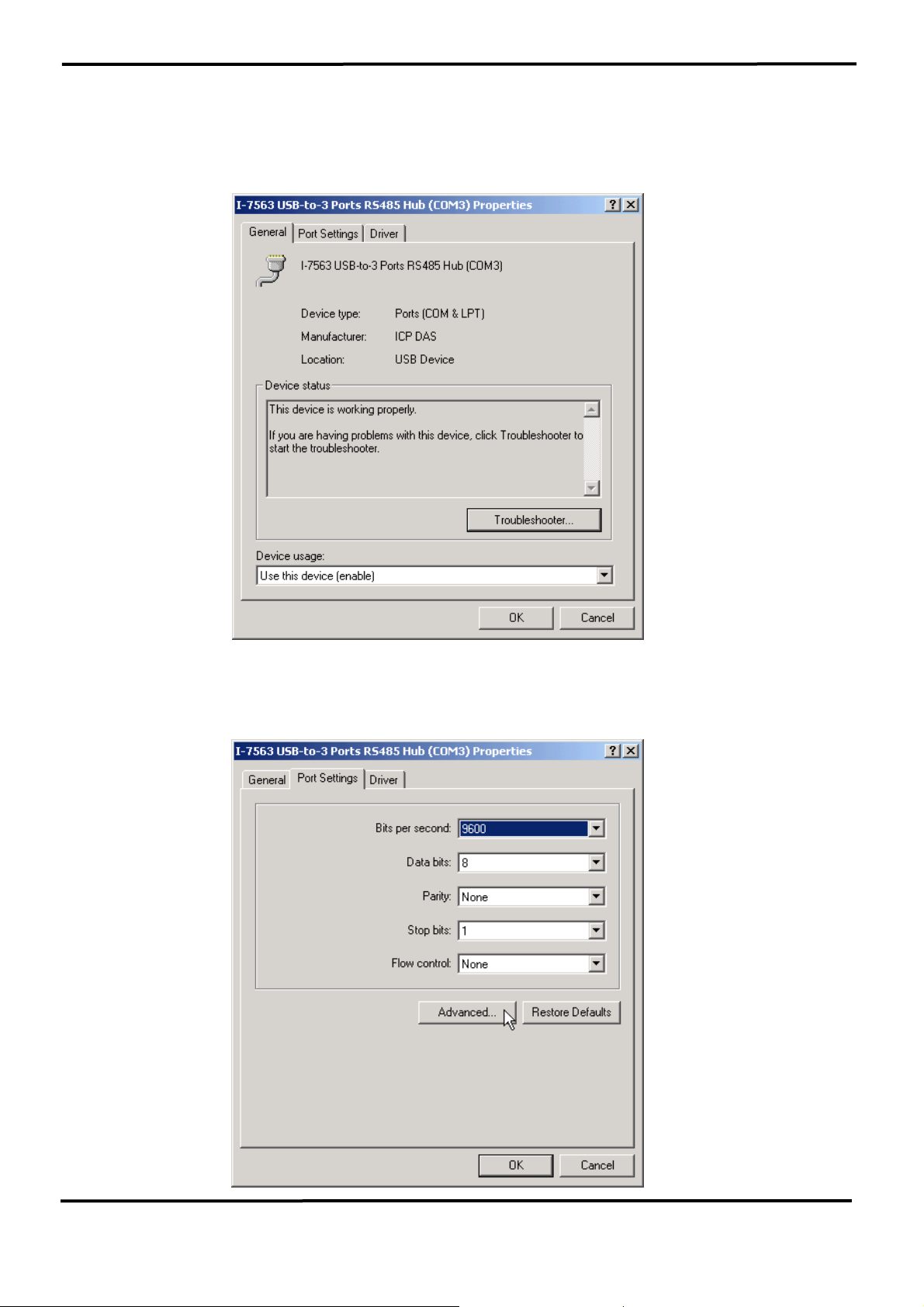
2. If you need to assign the COM Port name to another Port number, you
can double-click on the device (I-7563 USB-to-RS485 Hub) to view the
properties.
(The I-7563 cannot reassign the COM Port name to another
Port number under Win98 and Win98SE.)
3. Once the properties window opens click on the Port Settings tab. Then
click on the advanced button.
7000 Bus Converter User’s Manual (Version 1.8 Jan/2006, 7PH-006-18) --------------- 53
Page 54
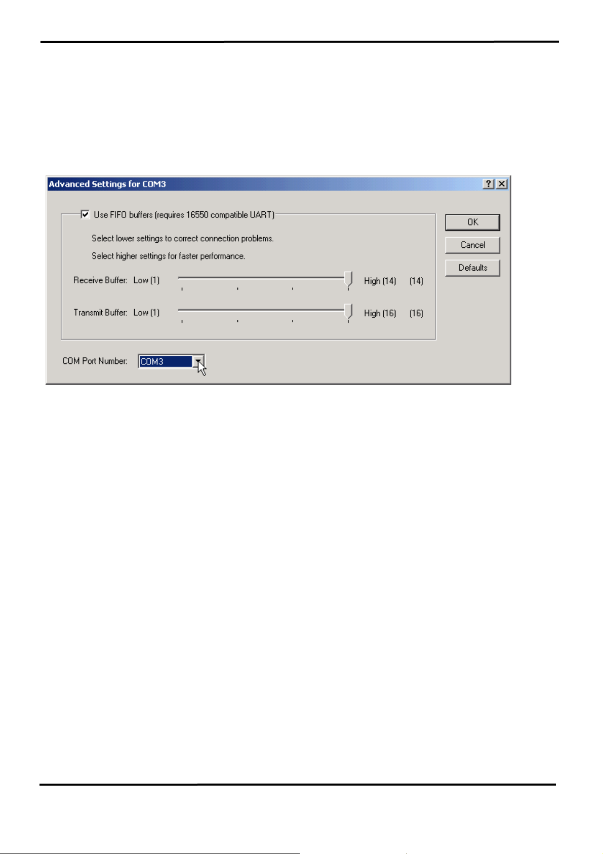
4. The Advanced Settings dialog box will now be displayed. Click on the
COM Port Number drop down box to check what other port numbers are
available. If, for instance, Windows has assigned COM5 to the device, you
may try to reassign it to a lower unused port number. Click OK when
finished. Try running HyperTerminal to test whether the new port number
is OK.
Note: Some software programs may only support Ports up to COM4 and
may not work if the port is assigned to COM5 or higher.
5. Once you have verified that the device has been properly installed, you
may now proceed to use the USB-to-3 Ports RS485 Hub to connect to
serial devices. Attach the serial device to the serial port of the adapter and
then connect the USB connector to the USB port of your computer. Use
the supplied driver for the serial device if needed.
7000 Bus Converter User’s Manual (Version 1.8 Jan/2006, 7PH-006-18) --------------- 54
Page 55
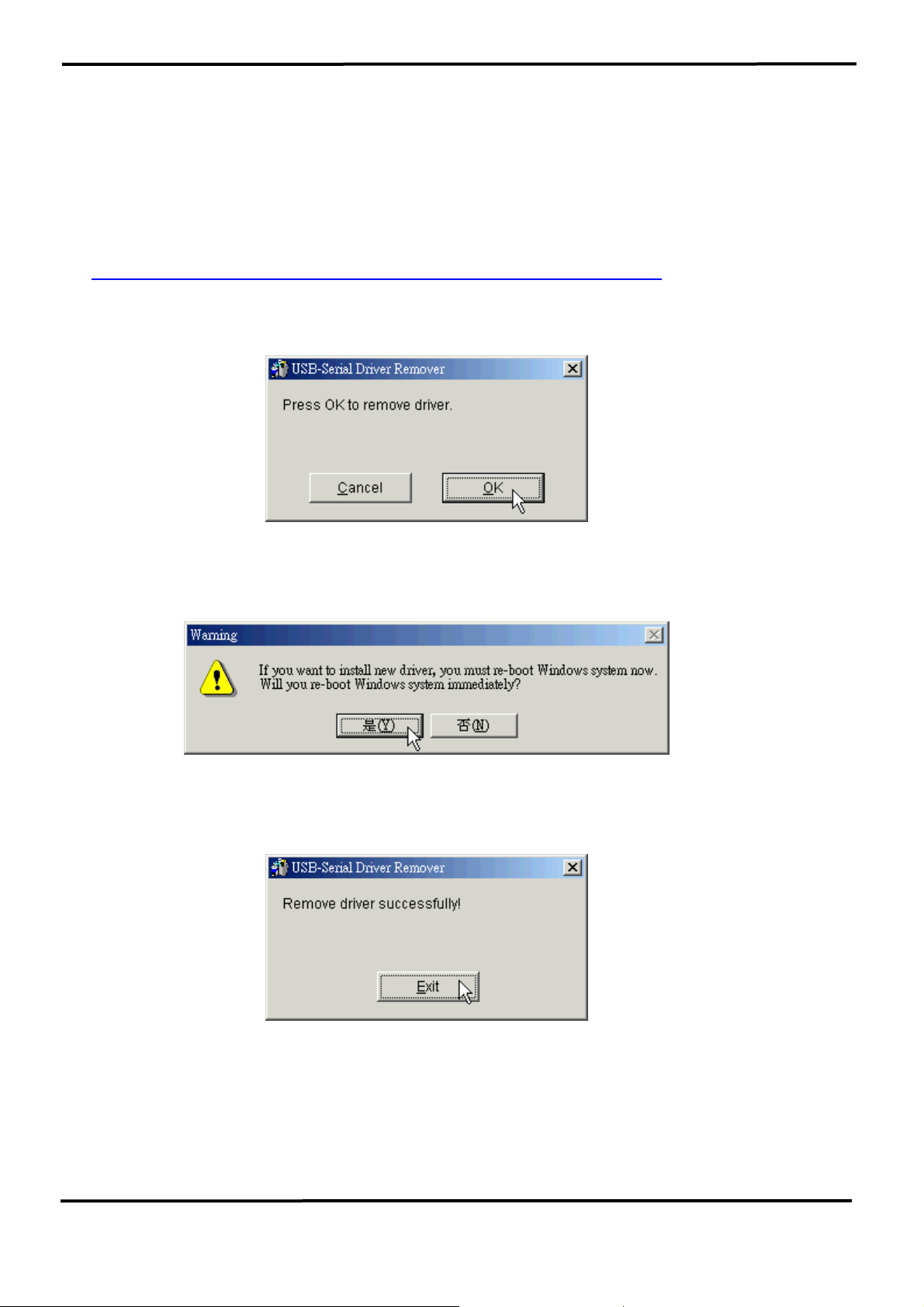
3.3.5 Uninstalling the Device Driver
It is easy to uninstall the USB to Serial device driver:
1. Run the DRemover98_2K.exe Uninstall program which can be found on
the Package CD, \Napdos\7000\756x\7563 or at
ftp://ftp.icpdas.com/pub/cd/8000cd/napdos/7000/756x/7563
2. The uninstall program will then prompt you if you want to remove the
utility program. Click OK to continue.
3. After the uninstall is complete, the program will prompt you to restart
Windows. Click “Yes” to continue.
4. Windows will show a dialog box to notify you that the driver was
removed successfully. Wait for Windows to restart your computer.
7000 Bus Converter User’s Manual (Version 1.8 Jan/2006, 7PH-006-18) --------------- 55
Page 56
y
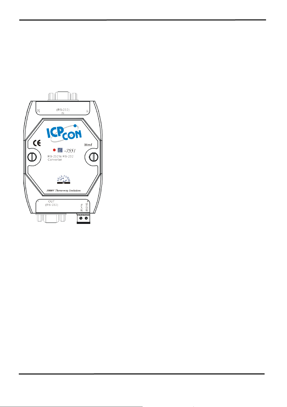
4. I-7551 : RS-232 to RS-232 Converter
4.1 I-7551 Pin Assignment and Specifications:
Introduction
The I-7551 Photo coupler provides a complete
full-duplex (including control signal) electrical
isolation channel between two RS-232 devices.
This isolation is an important consideration if a
system uses different power sources, has noisy
signals or must operate at different ground
potentials.
The I-7551 has the option of reconfiguring which
control signal is used. CTS can be selected
instead of DSR and RTS instead of DTR.
The I-7551 incorporates two DC-to-DC
converters; the isolation site of I-7551 is located
in the input and output interface circuit. In other
words, I-7551 is three- way isolation RS-232-toRS-232 converter.
Specifications
z Input:
RS-232 (TxD, RxD, CTS, RTS, GND or TxD, RxD,
DSR, DTR, GND)
z Output:
RS-232 (TxD, RxD, CTS, RTS, GND or TxD, RxD, DSR,
DTR, GND)
z Three-way Isolation voltage: 3000VDC
z Optical isolation: 2500V rms
z Communication speed: 115.2K bps, Max
z Distance Max: 15Meters
z Power requirements: +10V dc ~ +30V dc
z Power consumption: 1.5 W max.
z Storage temperature: -25℃ to +75℃
z Humidit
: 5~ 95%
7000 Bus Converter User’s Manual (Version 1.8 Jan/2006, 7PH-006-18) --------------- 56
Page 57
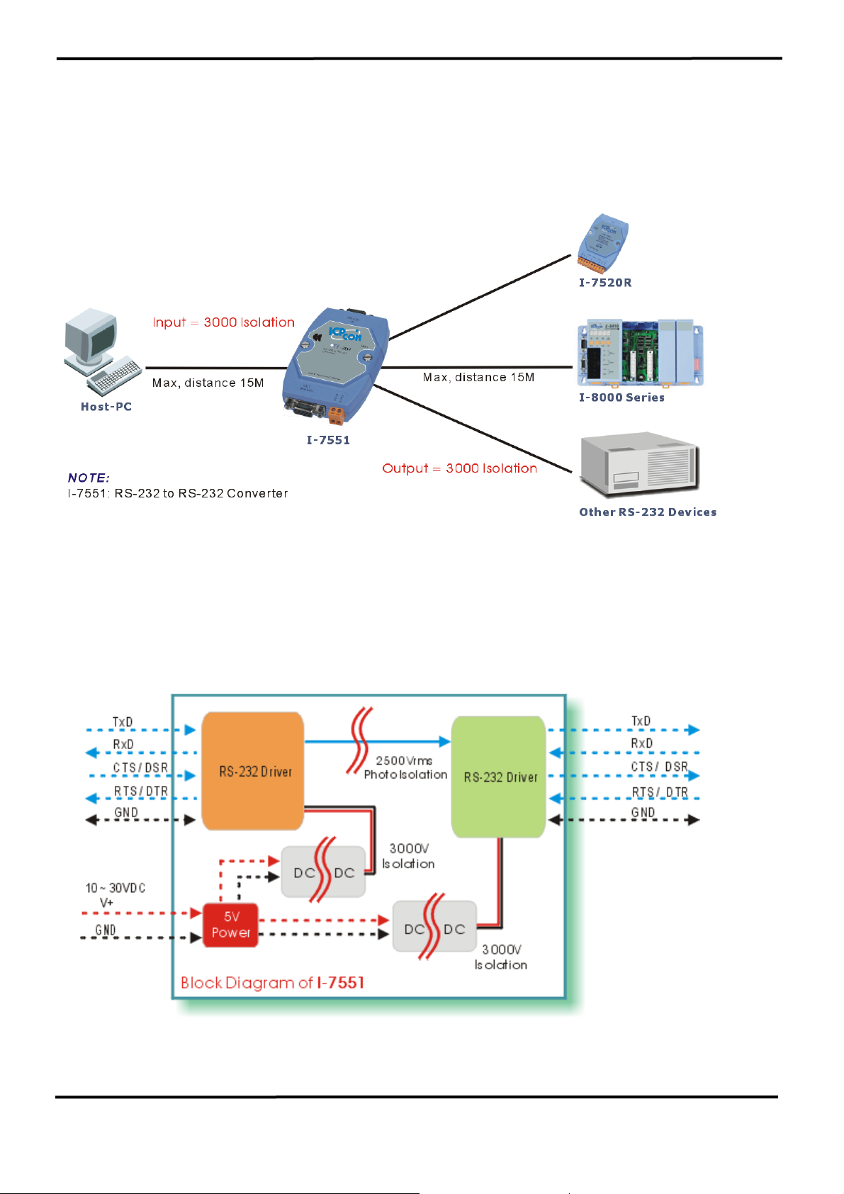
4.1.1 The I-7551 System Network Configuration:
• Multiple Baud Rate
• Multiple Data Format
4.1.2 The I-7551 Block Diagram:
7000 Bus Converter User’s Manual (Version 1.8 Jan/2006, 7PH-006-18) --------------- 57
Page 58
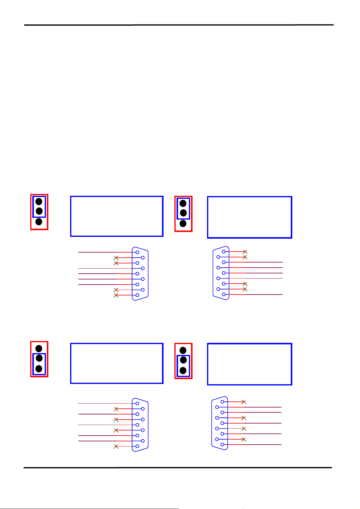
4.1.3 I-7551 has two different output types.
Selecting the I-7551 output type.
NOTE: The type1 and type2 couldn’t be used simultaneously, which
means that you can only select 1 type to output.
Type 1:
Input :TxD, RxD, CTS, RTS, GND. Output :TxD, RxD, CTS, RTS, GND.
Type 2:
Input :TxD, RxD, DSR, DTR, GND. Output : TxD, RxD, DSR, DTR, GND.
Type1 and Type2 Jumpers settings:
NOTE: RXD and TXD are permanent setting.
For type 1: Set the JP1 jumper to positions 2 and 3.
Set the JP2 jumper to positions 2 and 3.
JP1
3
2
1
Type 1:
For Pin8 “CTS”
Default setting
GND_IN
CTS_IN
TXD_IN
RTS_IN
RXD_IN
IN
5
9
4
8
3
7
2
6
1
JP2
DB9_Female
For type 2: Set the JP1 jumper to positions 1 and 2.
Set the JP2 jumper to positions 1 and 2.
JP1
3
2
1
Type 2:
For Pin6 “DSR”
IN
GND_IN
DTR_IN
TXD_IN
RXD_IN
DSR_IN
5
9
4
8
3
7
2
6
1
JP2
3
Type 1:
2
For Pin7 “RTS”
1
Default setting
OUT
1
6
2
7
3
8
4
9
5
DB9_Male
3
Type 2:
2
For Pin4 “DTR”
1
OUT
1
6
2
7
3
8
4
9
5
RXD_OUT
RTS_OUT
TXD_OUT
CTS_OUT
GND_OUT
DSR_OUT
RXD_OUT
TXD_OUT
DTR_OUT
GND_OUT
DB9_Female
DB9_Male
7000 Bus Converter User’s Manual (Version 1.8 Jan/2006, 7PH-006-18) --------------- 58
Page 59
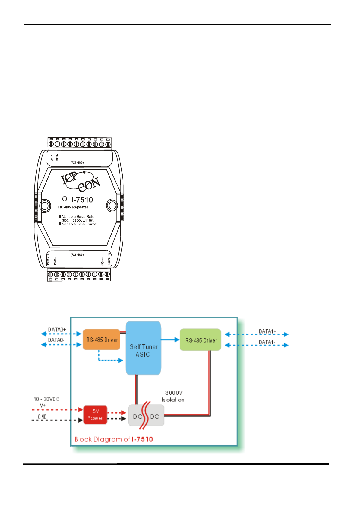
5. Repeater series: I-7510 / I-7510A / I-7510AR / I-7513
5.1 I-7510:
5.1.1 Pin Assignment and Specifications:
7510: RS-485 Repeater
• Input: two-wire RS-485, (D+, D-)
• Output: two-wire RS-485, (D+, D-)
• Speed: “Self Tuner” inside, auto switching
baud rate, from 300 to 115200 BPS
• Isolation voltage: 3000V
• Connector: plug-in screw terminal block
• Power requirements: +10V dc ~ +30V dc
• Power consumption: 2.2W(Max)
5.1.2 Block Diagram:
7000 Bus Converter User’s Manual (Version 1.8 Jan/2006, 7PH-006-18) --------------- 59
Page 60
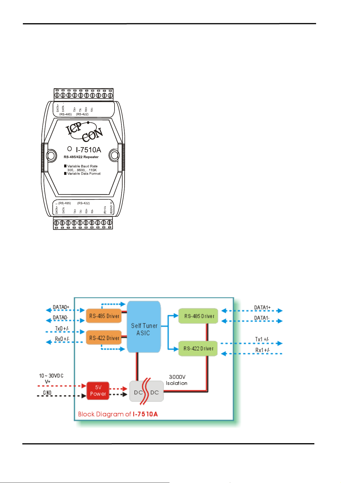
5.2 I-7510A:
5.2.1 Pin Assignment and Specifications:
7510A: RS-485/RS-422 Repeater
• Input: RS-485/RS-422
• Output: RS-485/RS-422
• Speed: “Self Tuner” inside, auto switching
baud rate, from 300 to 115200 bps
• Isolation voltage: 3000V
• Connector: plug-in screw terminal block
• Power requirements: +10V dc ~ +30V dc
• Power consumption: 2.2W(Max)
5.2.2 Block Diagram:
7000 Bus Converter User’s Manual (Version 1.8 Jan/2006, 7PH-006-18) --------------- 60
Page 61
5.3 I-7510AR:
5.3.1 Pin Assignment and Specifications:
Introduction
I-7510AR is exactly the same as I-7510A except
for the isolation site, The isolation site of I-7510A
is located in the input interface circuit, but the
isolation site of the I-7510AR is located in the
input and output interface circuit. In other words,
I-7510AR is three- way isolation repeater
module.
( RS-485 )
RS-422/485 Repeter
Variable Baud Rate
300,..9600,..115.2K
Variable Rate Format
( RS-422 )
I-7510AR
( RS-485 ) ( RS-422 )
Specifications
• Input: RS-485/RS-422
• Output: RS-485/RS-422
• Speed: “Self Tuner” inside, auto switching
baud rate, from 300 to 115200 bps
• Isolation voltage: Three-way 3000Vdc
• Connector: plug-in screw terminal block
• Power requirements: +10V to +30VDC
• Power consumption: 2.2W(Max)
7000 Bus Converter User’s Manual (Version 1.8 Jan/2006, 7PH-006-18) --------------- 61
Page 62
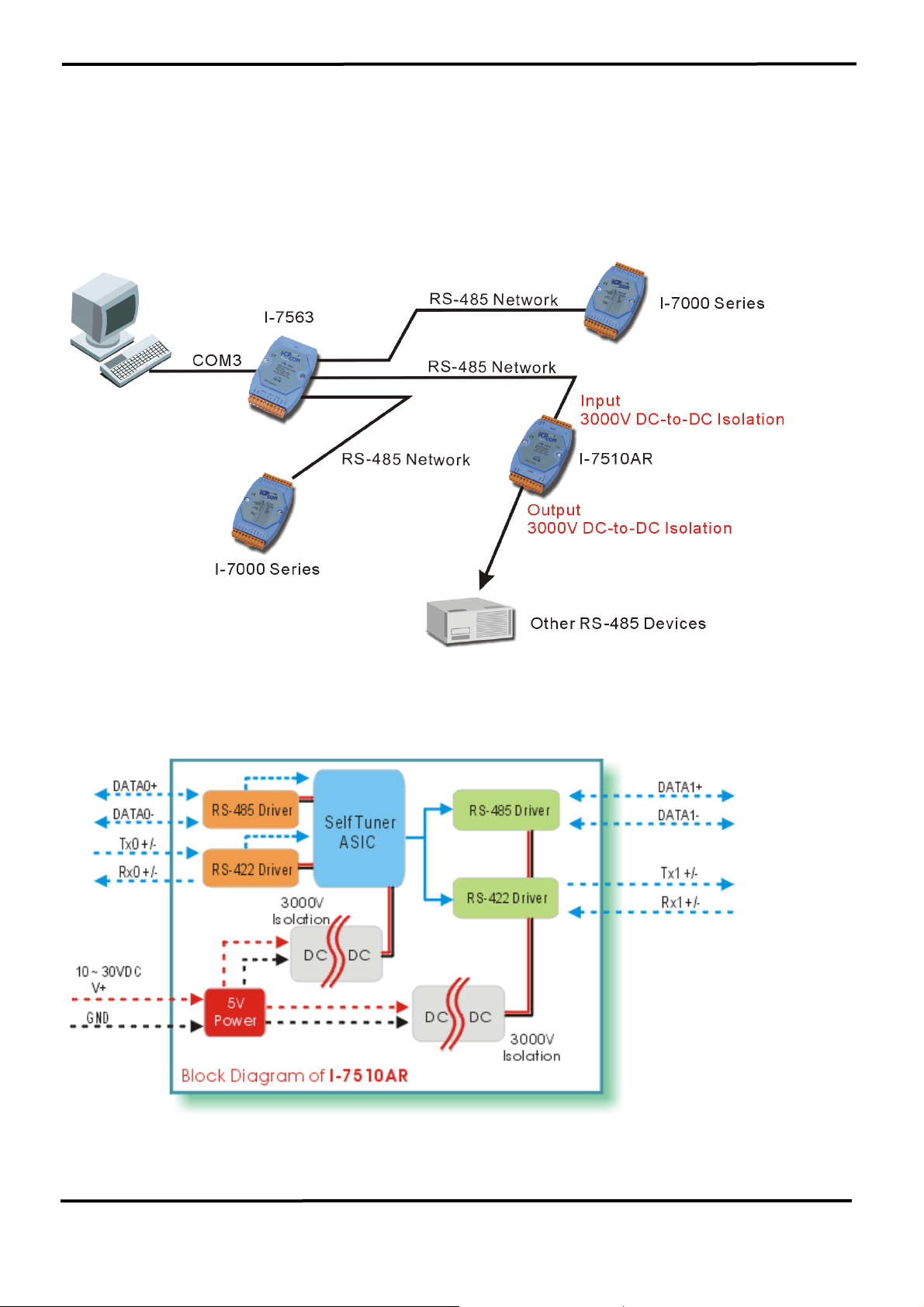
5.3.2 System Network Configuration:
• Multiple Baud Rate
• Multiple Data Format
5.3.3 Block Diagram:
7000 Bus Converter User’s Manual (Version 1.8 Jan/2006, 7PH-006-18) --------------- 62
Page 63
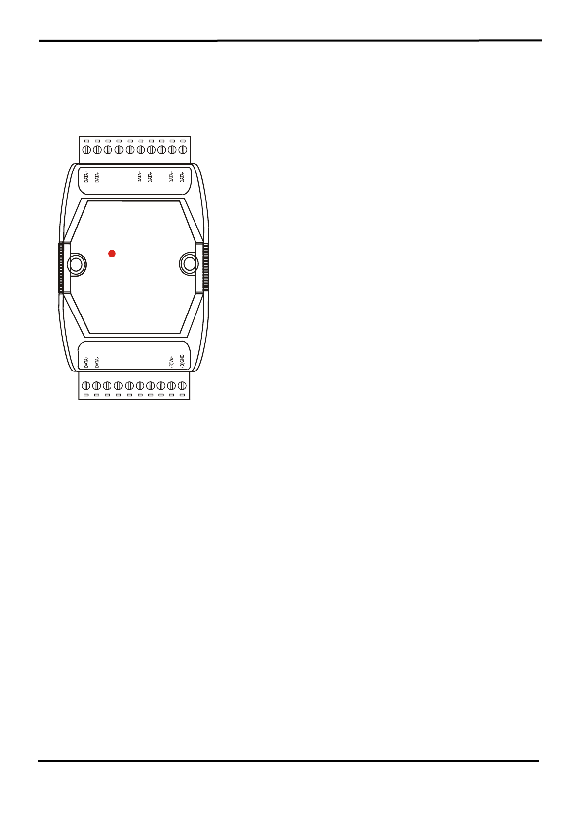
5.4 I-7513:
5.4.1 Pin Assignment and Specifications:
Introduction
( CH 1 ) ( CH 2 ) ( CH 3 )
RS-485 HUB
One channel RS-485 Input
Three channels RS-485 Output
( CH 0 )
Specifications
I-7513
I-7513 is one channel RS-485 with a three
way Active Star Wiring Hub. The unit has 3
independent RS485 output channels each with
their own driver, which can transmit signals
along 4,000 ft (1.2Km). Of cable on each
channel.
I-7513 includes both Hub and Repeater
function. So each output channel can be
connected anther hub.
The isolation site of I-7513 is located in the input
and output interface circuit. In other words,
I-7513 is three- way isolation module.
• Input: one port RS-485, (D+, D-)
• Output: three-port RS-485, (D+, D-)
• Speed: “Self Tuner” inside, auto switching
baud rate, from 300 to 115200 bps
• Isolation voltage: Three-way 3000Vdc
• Connector: plug-in screw terminal block
• Power requirements: +10V dc ~ +30V dc
• Power consumption: 2.2W(Max)
• Each channel on the hub is driven by it's
own RS-485 driver.
• Each channel maximum line length about
of 4000 ft.
7000 Bus Converter User’s Manual (Version 1.8 Jan/2006, 7PH-006-18) --------------- 63
Page 64
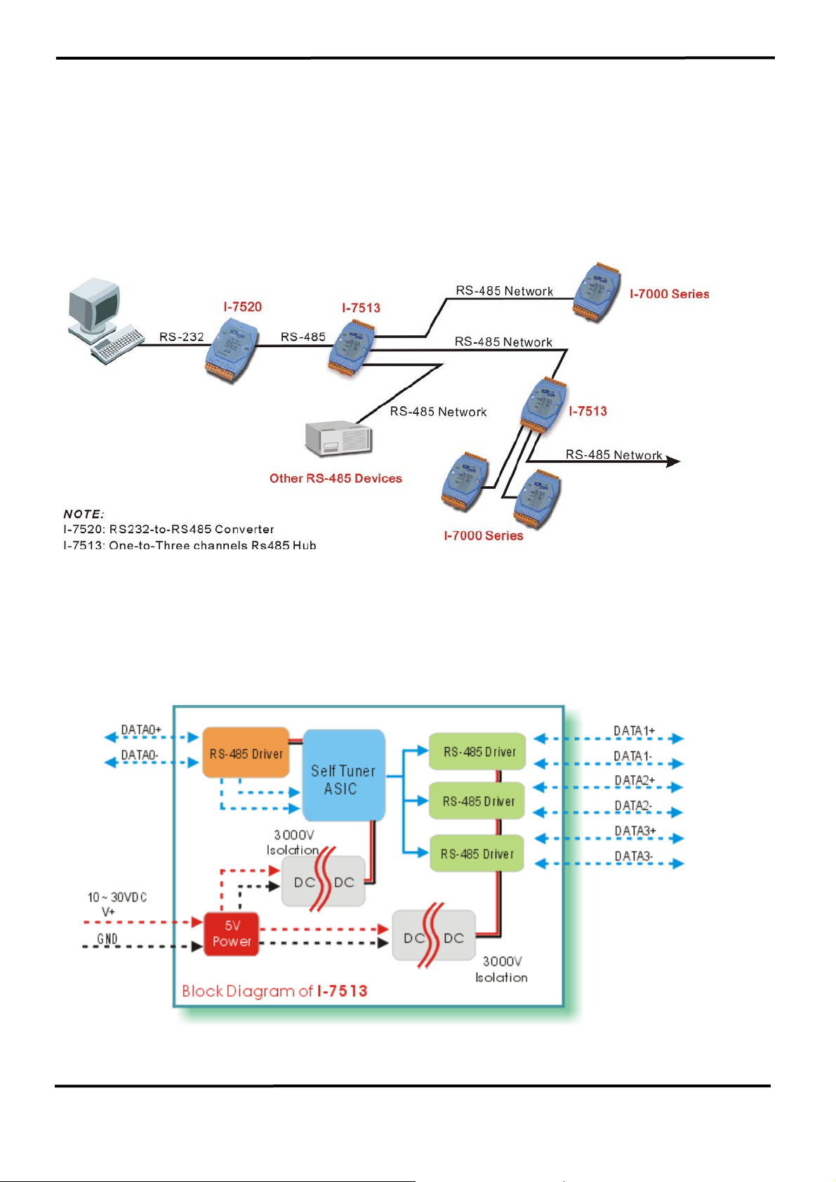
5.4.2 System Network Configuration:
• Multiple Baud Rate
• Multiple Data Format
5.4.3 Block Diagram:
7000 Bus Converter User’s Manual (Version 1.8 Jan/2006, 7PH-006-18) --------------- 64
Page 65
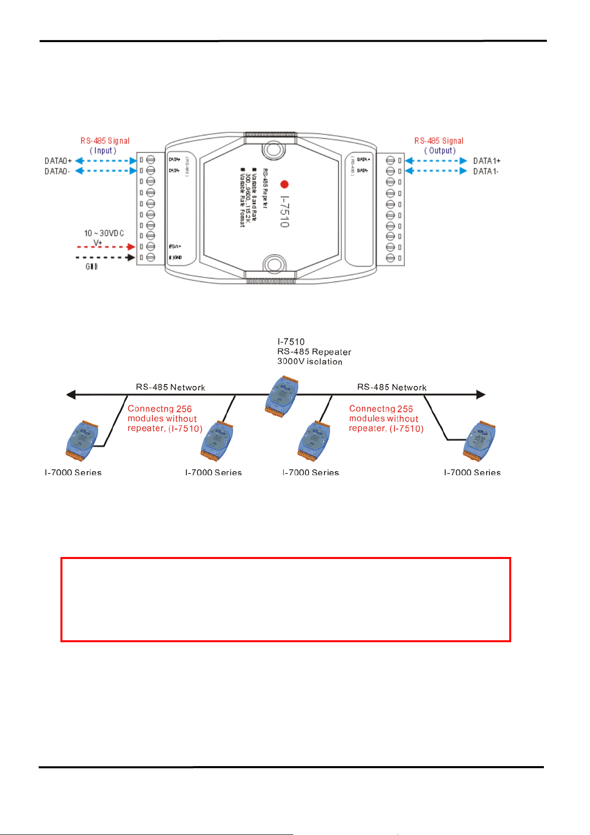
5.5 Basic Wire Connections for I-7510
(1) Extends RS-485 network if the path is over 4000 ft or 1.2 Km
(2) Extends RS-485 network if connecting over 256 modules
(3) Cuts a long RS-485 path into several isolated short RS-485 paths
for protection
7000 Bus Converter User’s Manual (Version 1.8 Jan/2006, 7PH-006-18) --------------- 65
Page 66
y
6. 7000 RS-485 Networking
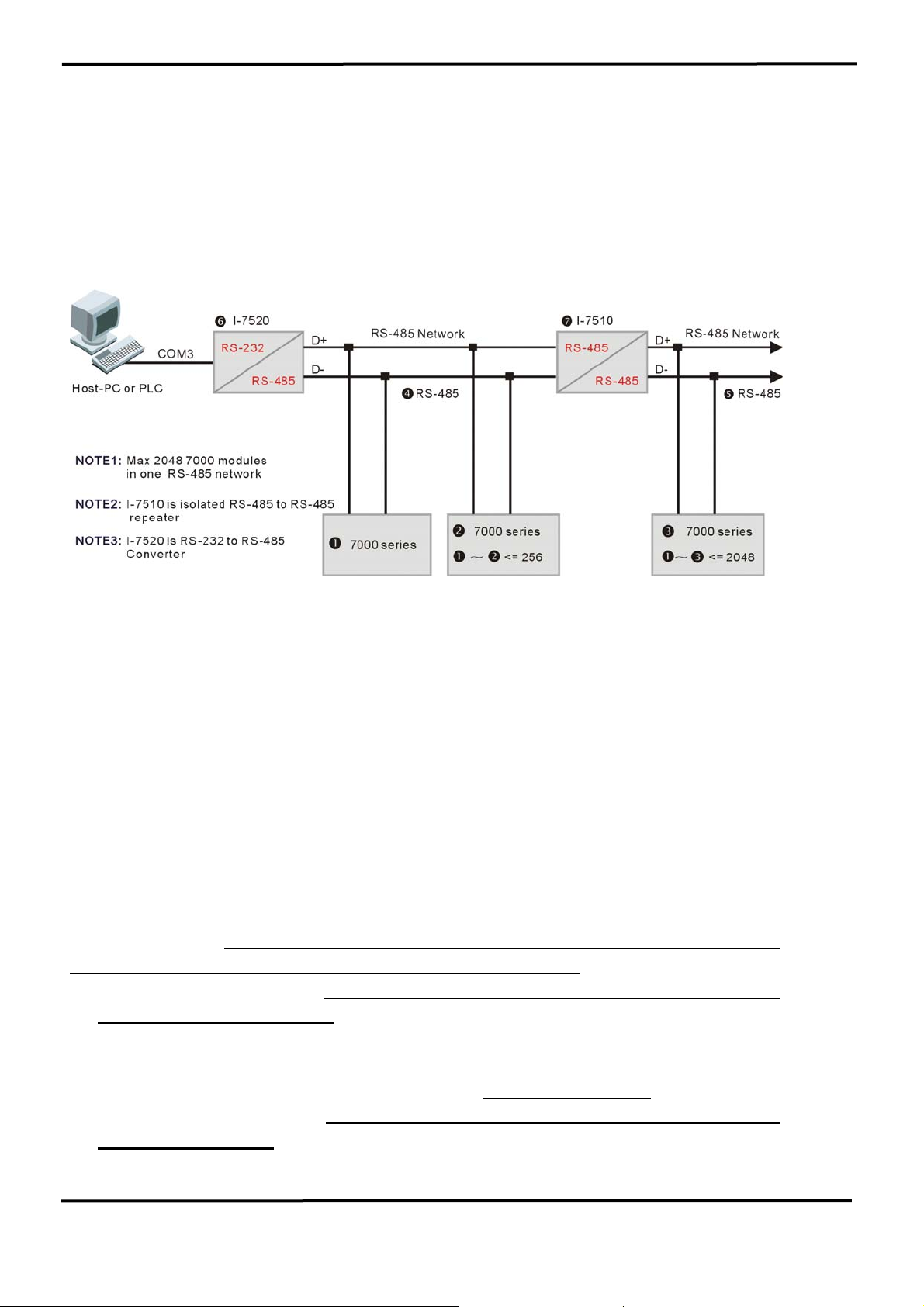
6.1 Standard/Isolation Configuration
Dais
-Chain Configuration.
The Host PC/PLC will send out a command string from its RS-232
port. The s7520 will convert these RS-232 signals into a RS-485 signal
and isolate the host from qRS-485 network.
The 7000 series modules, including D/I, D/O, A/D, D/A,
Timer/Counter and MMI modules, will be directly connected to qRS-485.
These 7000 series modules can connect a max. Of 256 modules to the
qRS-485 network without a repeater, the 7510. That it to say, there can
be 256 modules from n7xxx to o7xxx. If there are over 256 modules, the
repeater 7510 must be added to extend the qRS-485 to rRS-485. Then
there can be another 256 modules connected to the rRS-485 network.
This is the first function of the 7510.
The module address can be changed from 00 to FF a total of 256
max. Therefore
there are maxes. Of 256 modules in one RS-485 network
if all the modules communicate with the same speed.
(1) Because the 7000 can communicate with different baud rates in the
same RS-485 network, the n7xxx, o7xxx and p7xxx can be
communicated to HOST PC/PLC with a different baud rate.
(2) The 7000 series can be programmed to 1200, 2400, 4800, 9600,
19200, 38400, 57600, 115200,a total of
(3) The 7000 modules can share the same module address if their baud
8 different speed.
rates are different. For example,
n7xxx=module address 01, baud rate=1200
7000 Bus Converter User’s Manual (Version 1.8 Jan/2006, 7PH-006-18) --------------- 66
Page 67

o7xxx=module address 01, baud rate=9600
p7xxx=module address 01, baud rate=115200
These three modules can share the same RS-485 network, generated
by s7520.
(4) Therefore there is
256*8=2048 modules max. In one RS-485 network
with a repeater (7510).
The “search function” given in DCON_DOS can search for all these
2048 modules in one RS-485 network. Refer to “DCON_DOS.pdf” for
completely source listing of “search function”.
When the RS-485 network is
over 4000 ft or 1.2Km, the RS-485
repeater (7510) must be added to extend the RS-485 network. For
example, if the qRS-485 is over 4000 ft or 1.2 Km, the t7510 must be
added to extend qRS-485 to rRS-485. And if the rRS-485 is too long,
the user should use another 7510 to extend another RS-485 network. This
is the second function of 7510.
The
power ground of the 7000 series is common ground to the RS485 network. This feature is the same as the Adam 4000, Nudam 6000
and DATAFORTH 9B series.
Therefore all the modules in the same RS485 network are common ground. For example, the all modules between
n7xxx and o7xxx share the same qRS-485 network and all are common
ground. The qRS-485 length can be up to 4000 ft or 1.2 km, this is a very
long path. This long path makes the RS-485 network
very susceptible to
network noise by high energy transient in this environment. If this noise is
too great, all the modules in the RS-485 network may be
damaged
simultaneously. This is highly possible and occurs often in real world
applications. It is strongly recommended to add another isolation repeater,
the 7510, to break the long path RS-485 network into several short RS485 networks to avoid all the modules being damaged at the same time.
This is the third function of 7510.
7000 Bus Converter User’s Manual (Version 1.8 Jan/2006, 7PH-006-18) --------------- 67
Page 68
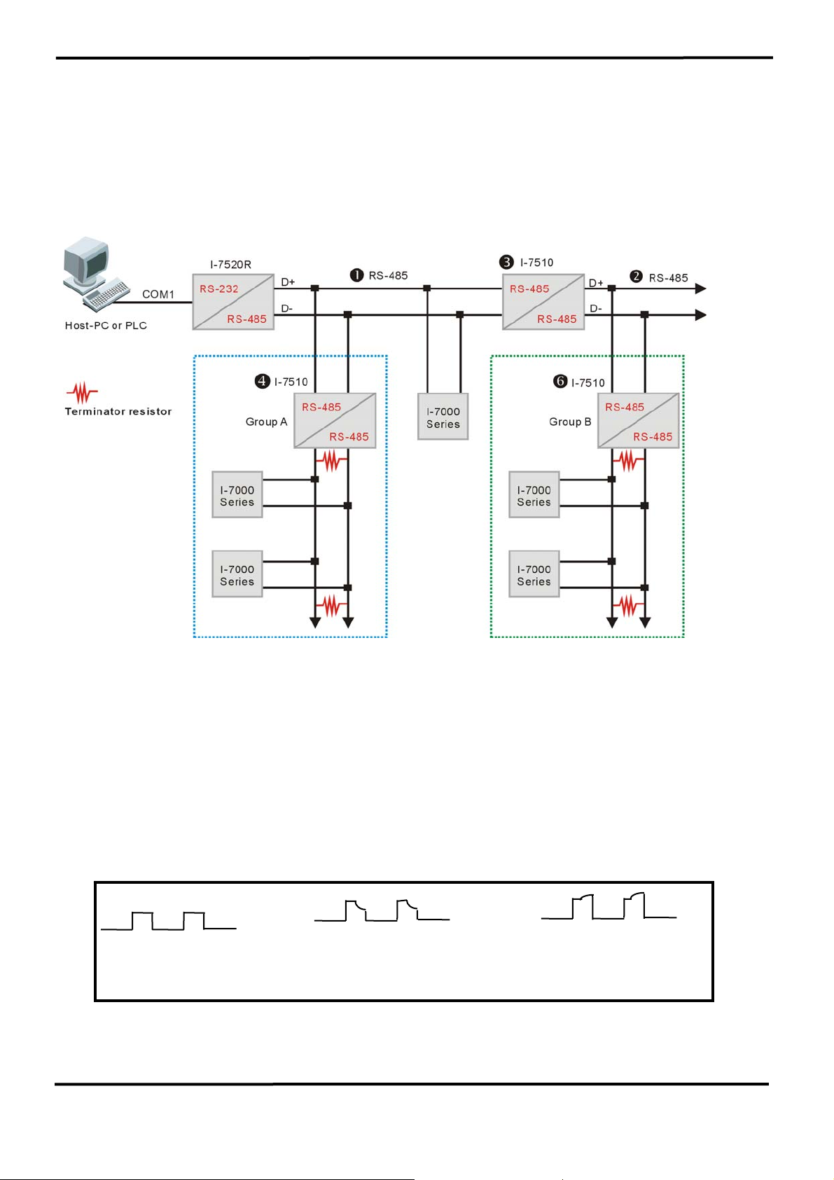
For example, the q7510, s7510 are used to isolate local modules
from nRS-485 network. If there is high energy transient on nRS-485
network, all the local modules will be safe.
Isolation Configuration (Strongly Recommended):
If the RS-485 network is not over 100 meters, the terminated
resistors are not needed. However, it may be necessary to insert two
terminated resistors at both end of the RS-485 segment. It is not easy to
calculate the value of a terminator resistor. The best way to do this is to
use an oscilloscope to check the RS-485 signal directly. If the impedance
match of RS-485 network is OK, the oscilloscope will show a very nice
square wave. If these square wave signals are distorted, the user will
need to insert two terminators at both end of the RS-485 segment.
OK
Resistor value of
terminator is too small
Resistor value of
terminator is too big
7000 Bus Converter User’s Manual (Version 1.8 Jan/2006, 7PH-006-18) --------------- 68
Page 69

It is recommended to use the “trial and error” rule. The trial and error
rules are given as follows:
(1) If the length of RS-485 is about 1.2 Km, try 330Ω first
(2) Run TEST.EXE of DCON_DOS
Select function_5, run continuously for at least 8 hours to make
sure communication is OK.
(3) If function_5 finds many communication errors, use an
oscilloscope to check the waveform. The waveform will tell you
whether the terminator is too small or too big. Then adjust your
terminator and run TEST.EXE again.
(4) If the correct terminators are found, run the TEST.EXE
continuously for at least 8 hours to make sure there are no
communication errors.
The function_5 of TEST.EXE, given in DCON_DOS, will automatically
read “testing command” from TEST.DAT and continuously perform “sendreceive-testing”. It will continuously test and record all testing results.
Therefore this function is especially designed for RS-485 network stability
evaluation. If you run this function_5 continuously for 8 hours and find no
check errors, this means that your RS-485 network is very stable. Also
this means that your terminators match well now.
NOTE 1: The value of the terminator depends on the RS-485 wire
used. If the RS-485 path is very long, don’t use a cheaper wire. It is
recommended to select a high quality wire
such as the Belden 1583A.
NOTE 2: The terminator is different for various applications.
Therefore we can’t provide a terminator with the 7520 or the 7510. The
user must choose the correct terminator by them self. It is recommended
to use a carbon, 1/4w resistor.
7000 Bus Converter User’s Manual (Version 1.8 Jan/2006, 7PH-006-18) --------------- 69
Page 70
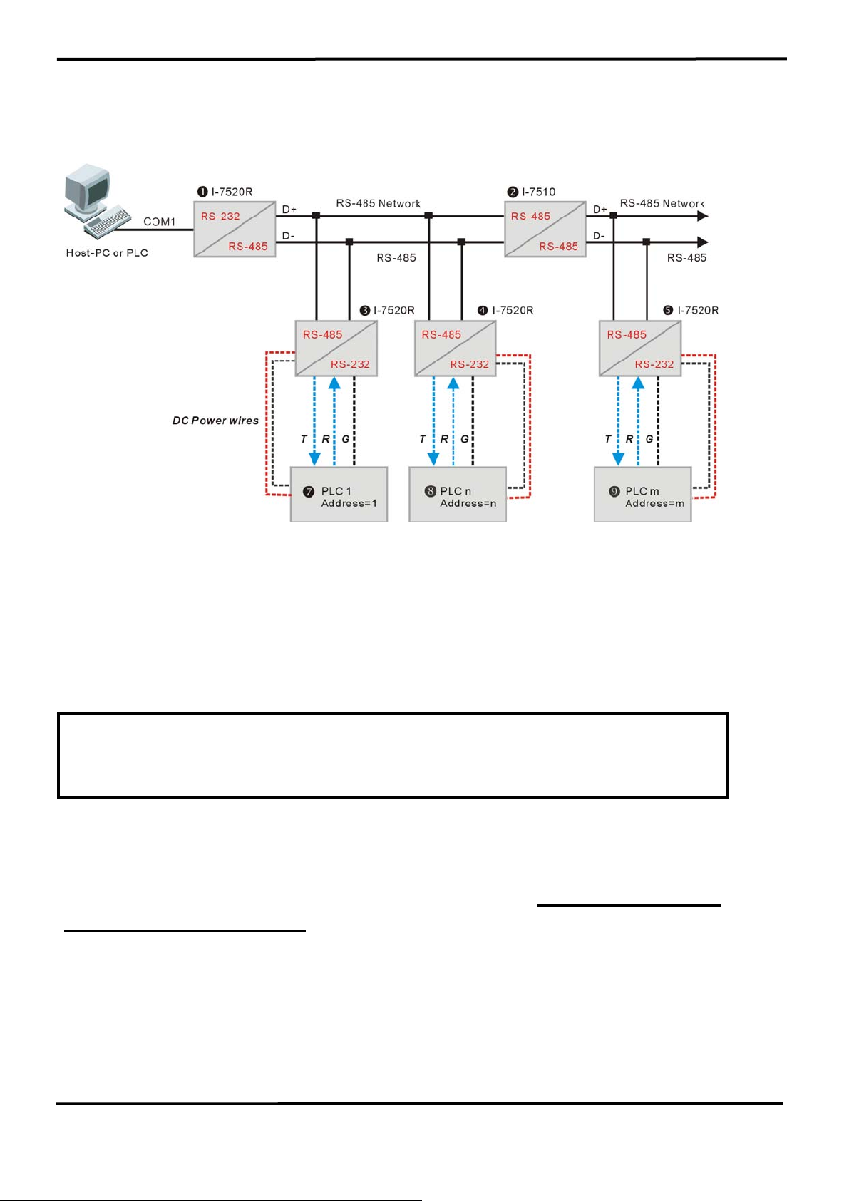
6.2 PLC Networking Applications
These PLCs can be used at different baud rates & different
configurations. For example,
PLC-1=1 start + 7 data + 1 stop=9-bit/byte, baud rate=1200
PLC-n=1 start + 8 data + 1 parity + 1 stop=11-bit/byte, baud rate=9600
PLC-m=1 start + 8 data + 1 parity + 2 stop=12-bit/byte, baud rate=115200
OMRON CQM1 = 1 start + 7 data + 1 even parity + 2 stop =11-bit/byte
OMRON C200 = 1 start + 7 data + 1 even parity + 2 stop = 11-bit/byte
The n7520 can be the 7520 or 7520R, refer to Sec. 2.5 for details.
The p7520R, q7520R, r7520R can be the 7520 or 7520R, refer to
Sec. 2.5 for details. In this configuration, the tPLC1, uPLCn, vPLCm
provides DC power to p7520R, q7520R, r7520R. This is the cheapest
to the 3000V high isolation. The user should not replace the 7520R, p, q,
r, with the 7520.
Refer to “DCON_DOS.pdf” for PLC networking software details.
7000 Bus Converter User’s Manual (Version 1.8 Jan/2006, 7PH-006-18) --------------- 70
Page 71
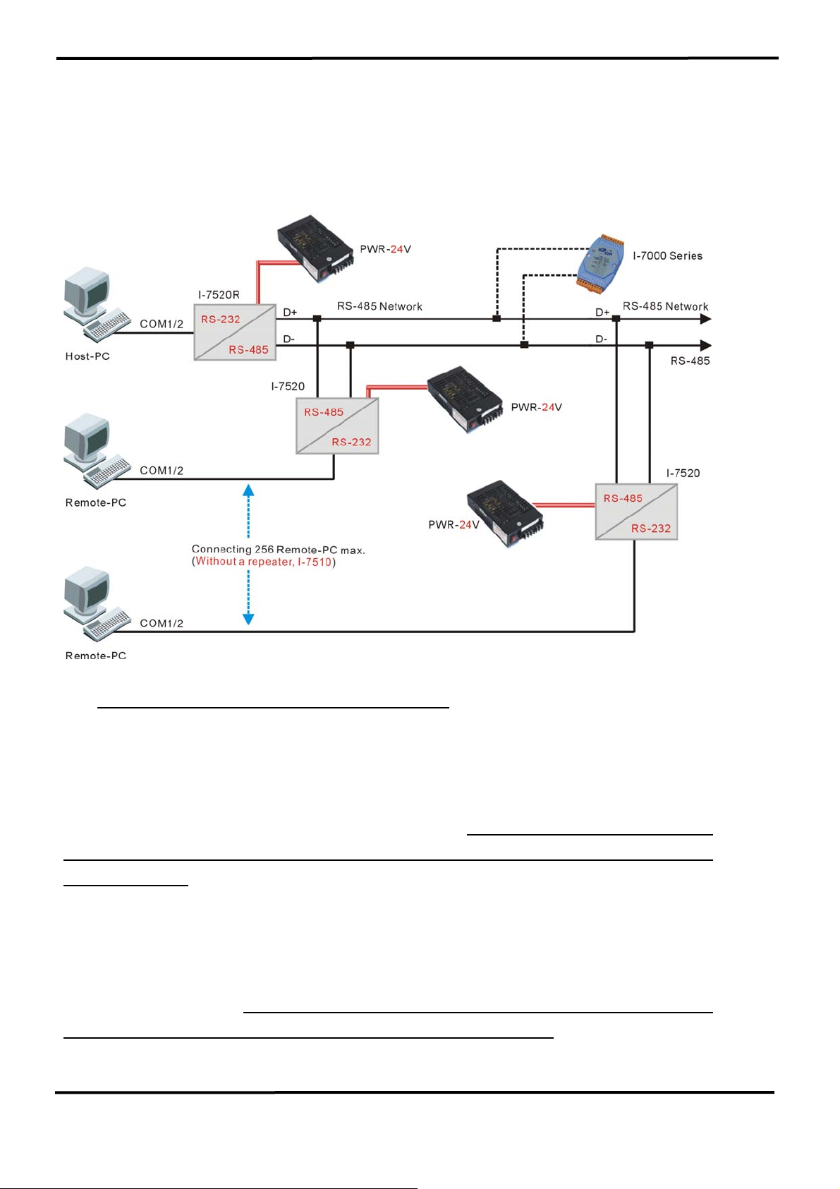
6.3 PC Networking Applications:
(For this application, we recommend to use i-7520U to replace the i-7520)
Every remote-PC must have a unique address. This unique address is similar to
the module address of the 7000 series. We call it a “slave-PC address”. The module
address of the 7000 series is limited to 256, but the slave-PC address is unlimited. The
user can connect thousands of PCs in one RS-485 network by using a repeater, the
7510.
Refer to “DCON_DOS.pdf” for software details. Using this software, the host-PC
can send out commands to remote-PCs, just like sending commands to the 7000
series modules. The remote-PC will receive these commands and execute the
command if the destination addresses matches it’s local address.
These remote-PC and 7000 series modules can use the same RS-485 network.
The host-PC can send out the 7000 series commands and send out PC-networking
commands at different times. The modules and remote-PCs will receive their
command respectively. This makes the network very low cost, with high flexibility and
reliability. This unique feature is not found elsewhere in the world.
7000 Bus Converter User’s Manual (Version 1.8 Jan/2006, 7PH-006-18) --------------- 71
Page 72
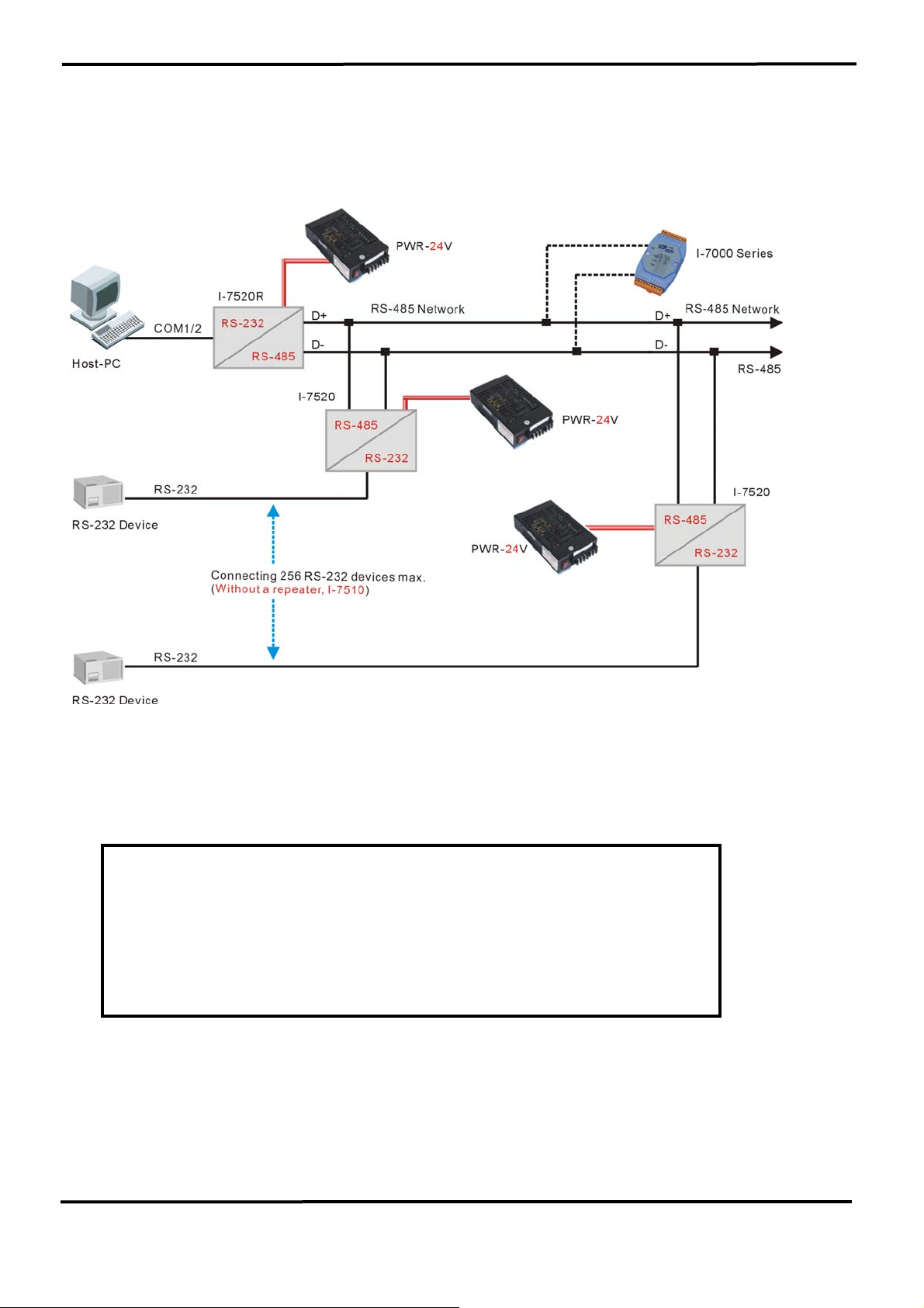
6.4 RS-232 Devices Network (For this application, we recommend to use i-7520U to replace the i-7520)
Some RS-232 devices can be connected to the 7000 RS-485
network very easily, just like the PC or PLC introduced in Sec 6.2 and Sec.
6.3. These RS-232 devices must adhere to 3 rules given as follows:
Rule 1: cannot send out the RS-232 signal in normal,
operating state.
Rule 2: every device has a unique device address
Rule 3: will not send out a RS-232 signal if the destination
address does not match with the device address
The software for RS-232 device networking and PLC
networking is very similar. The only difference is the command
format. The command format of PLC is always different for
different manufacturers. Refer to “DCON_DOS.pdf” for software
details.
7000 Bus Converter User’s Manual (Version 1.8 Jan/2006, 7PH-006-18) --------------- 72
 Loading...