

Page 1
E-M-HG2-S-XL-V3.4
Rotronic AG
Bassersdorf, Switzerland
Instruction Manual for Software
Version 3.4
Document Type
Document code Unit
HygroGen2: Humidity and Temperature Generator
with AutoCal, Chilled Mirror External Reference, Remote
Screen Share, Remote API and Range Extension options.
Instruction Manual
Document title
Instruction Manual
© 2020; Rotronic AG E-M-HG2-S-XL-V3.4
HG2-S and HG2-XL
Page 2

E-M-HG2-S-XL-V3.4
Rotronic AG
Bassersdorf, Switzerland
Advisory Notice
Document Type
Document code Unit
HygroGen2: Standard Supply Package
Document title
Contents of the Standard Supply Package HG2-S:
HG2-S HygroGen2 generator
HG2-DES Desiccant cell filled with molecular sieve (pre-installed)
IEC mains cable
HG2-FILL Water fill syringe (with tube)
HC2-S-S HC2A-S control probe (pre-installed) with calibration certificate
1
Sample Loop connector cover plugs
This Manual
Chamber door (according to customer's order)
2
HW4 software ID number
USB memory stick including saved test data and user manual
Contents of the Standard Supply Package HG2-XL:
HG2-XL HygroGen2 generator with integrated door
2 x HG2-DES Desiccant cells filled with molecular sieve (pre-installed)
IEC mains cable
HG2-FILL Water fill syringe (with tube)
HC2-S-S HC2A-S control probe (pre-installed) with calibration certificate
Sample Loop connector cover plugs
This Manual
HW4 software ID number
USB memory stick including saved test data and user manual
1
1
The calibration certificate included will vary according to the country of supply.
2
In some countries, the chamber door is delivered with the HygroGen2. Due to the diversity of chamber doors
and bungs, these are normally ordered separately and may be delivered in separate packaging.
© 2020; Rotronic AG E-M-HG2-S-XL-V3.4
Page 3

E-M-HG2-S-XL-V3.4
Rotronic AG
Bassersdorf, Switzerland
Table of Contents
Document Type
Document code Unit
HygroGen2: Table of Contents
Document title
1 Scope of Document 6
1.1 Introducing the HygroGen2 6
1.2 Temperature and Humidity References 6
1.3 Optional Enhanced Features 7
2 Setting up the HygroGen2 9
2.1 Physical Location 9
2.2 Electrical Supply 9
i. Power Isolation 9
ii. Earthing 9
iii. Earth Leakage Current 9
iv. Overcurrent Protection 10
v. Voltage Rating 10
vi. Mains Filtration 10
vii. Conductive Pollution 10
2.3 HygroGen2 Assembly 11
HG2-S 11
i. HygroGen2-S Doors 12
ii. Desiccant Cell 12
iii. External Sample Loop 12
iv. HC2-S Control Probe 12
HygroGen2-XL 13
i. HygroGen2-XL Door 14
ii. HygroGen2-XL Shelves 14
iii. HygroGen2-XL Cable Management 15
iv. Desiccant Cells 15
v. External Sample Loop 16
vi. HC2-S Control Probe 16
2.4 Water Reservoir 17
i. To fill the HygroGen2: 17
ii. To empty the HygroGen2: 18
iii. Ultra-violet sterilisation lamp 18
3 HygroGen2 - Basic Operation 19
3.1 Switching On 19
3.2 Upgrading HygroGen2 Firmware 20
Updating HygroGen2 firmware from a version 3.1 or earlier 20
Updating HygroGen2 firmware from an earlier version of 3.3.x.x 20
Updating HW4 version 22
3.3 Configuration Mode Settings 25
Network Settings 25
Date and Time Settings 27
International Keyboard 27
External Monitor 27
Touch Screen Calibration 28
3.4 HygroGen2 Touchscreen Interface 29
Controller Home Screen 29
© 2020; Rotronic AG E-M-HG2-S-XL-V3.4
Page 4

E-M-HG2-S-XL-V3.4
Rotronic AG
Bassersdorf, Switzerland
Table of Contents
Document Type
Document code Unit
HygroGen2: Table of Contents
Document title
i. Navigation (items 1, 10 & 14) 29
ii. Temperature and Humidity Set-Points (items 3 & 7) 30
iii. Temperature and Humidity Control (items 5 & 9) 30
Trend Screen 31
i. Trace selection (item 4) 31
ii. Trend Axes (items 2 & 3) 31
Programmer Screen 32
i. Program Selection (items 1 & 2) 32
ii. Step Selection (item 3) 32
iii. Run/Stop (item 4) 32
iv. Edit Program (item 5) 33
Edit Program Screen 33
i. Select a Program to Edit 33
ii. Edit a Program Name 33
iii. Edit a Step 33
iv. Insert or Delete a Step (items 6 & 7) 34
v. Ramp or Soak (item 2) 34
vi. Timing Tolerances (items 10 & 11) 34
vii. Temperature only Program (item 12) 34
viii. Programmer Screen 34
Settings Screen 35
i. Activation of Enhanced Features 35
ii. HygroGen Information 36
iii. Remote Support 36
iv. Connections to Network File Servers 38
4 HygroGen2 Enhanced Features 39
4.1 AutoCal 41
Top Level Menu and Programmer Function 41
AutoCal Reference 41
AutoCal Compatible Probes 41
AutoCal Screen 42
AutoCal Program Edit 42
Tolerance and Sample Size 43
AutoCal Operation and Best Practices 44
Customising the PDF Calibration Certificate 46
Reference Information 47
4.2 Chilled Mirror Reference Systems 49
Connecting and Configuring an External Reference 50
Measurement Type (MBW only) 52
Corrections (MBW only) 53
Calibration Info (MBW & S8000) 55
Advanced (Command Line interface) (MBW only) 55
Best Practices and Precautions 55
i. Dew/Frost control 55
ii. Mirror Cleaning 56
© 2020; Rotronic AG E-M-HG2-S-XL-V3.4
Page 5

E-M-HG2-S-XL-V3.4
Rotronic AG
Bassersdorf, Switzerland
Table of Contents
Document Type
Document code Unit
HygroGen2: Table of Contents
Document title
iii. Decontamination of HygroGen2 chamber 56
iv. Super Cooled Water: Dew or Frost Films. Force Frost Threshold 56
v. Extremes of Temperature and Humidity 57
4.3 Remote Control 58
Remote Screen Share 58
RemoteAPI 60
4.4 Range Extensions 64
5 General Operational Considerations 65
Water in the Chamber 65
Below Ambient Temperature Operation 65
Above Ambient Temperature Operation 66
Probe Insertion Depth 66
Protective Filters 67
Low Water Level Alarm 67
Water Level Indicator Calibration 67
5.2 Switching off the HygroGen2 68
Shut Down 69
Transit 69
5.3 Preparing the Unit for Transit or Storage 70
6 HW4 Embedded 71
6.1 HW4 Set Up and Getting Started 71
6.2 HW4 Installation and Registration 72
6.3 HW4 Support 72
6.4 Data Logging in HW4 73
Test Instrument Data 73
Control HC2-S [HW4v3.9] 74
7 External PC Peripherals 75
7.1 USB Keyboard and Mouse 75
International Keyboard Layouts 75
7.2 External Monitor 76
8 Servicing and Maintenance 77
8.1 Control HC2-S Calibration 77
Removing Control HC2-S HG2-S 77
Removing Control HC2-S HG2-XL 77
8.2 Desiccant 78
Changing Desiccant 79
Choice of Desiccant 79
8.3 HygroGen2 Cleaning 80
External surfaces 80
Air Inlet Filters – HG2-S 80
Air Inlet Filters – HG2-XL 80
Chamber 82
Purging internal pipes 82
8.4 Annual Servicing of HygroGen2 82
A1: Calibration Reference Options 83
© 2020; Rotronic AG E-M-HG2-S-XL-V3.4
Page 6

E-M-HG2-S-XL-V3.4
Rotronic AG
Bassersdorf, Switzerland
Table of Contents
Document Type
Document code Unit
HygroGen2: Table of Contents
Document title
A1.1 Internal RH Probe Reference 83
A1.2 External RH Probe Reference 84
A1.3 Chilled Mirror Reference 84
A2: Temperature Control 87
A3: Validation – Requirements and Accessories 88
B2: HygroGen2 / Screen Messages 89
B3: HygroGen2-S Specification 90
B4: HygroGen2-XL Specification 91
B5: HygroGen2 Order Codes: 92
C1: HygroGen2 Warranty Statement 95
C2: Our Global Locations 96
D1: HygroGen2 Uncertainty Framework - Internal RH Probe 97
D2: HygroGen2 Uncertainty Framework - External RH Probe 98
D3: HygroGen2 Uncertainty Framework - Chilled Mirror Reference 99
D4: Dew Point Uncertainty Analysis 100
© 2020; Rotronic AG E-M-HG2-S-XL-V3.4
Page 7

E-M-HG2-S-XL-V3.4
Rotronic AG
Bassersdorf, Switzerland
Instruction Manual
Instruction Manual for Software
Version 3.4
Document Type
Document title
Document code Unit
HygroGen2: Humidity and Temperature Generator
with AutoCal, Chilled Mirror External Reference, Remote
Screen Share, RemoteAPI and Range Extension options.
Page 6 of 101
1 Scope of Document
This instruction manual refers to both HygroGen2 models: HG2-S and HG2-XL, running
software version 3.3. To determine the software version that your instrument is running, please
refer to the Settings Screen as shown in section 3.4.5. For version 1.x.x, the software revision
number is displayed by pressing the “HG Info” button; for version 2.0, select “Info” from the
“Service” drop-down menu; for version 2.1 and later, select “HygroGen2 Info” from the
“Support” drop-down menu. Equivalent manuals are available on www.rotronic.com for
HygroGen2 instruments running software versions 1.x. and 2.x.
For instructions on how to upgrade to version 3.3 please see Section 3.2.
1.1 Introducing the HygroGen2
The HygroGen2 is a generator of controlled relative humidity and temperature environments,
primarily for use in calibrating humidity instrumentation, but is also well suited to the
calibration of temperature instrumentation, particularly those used for the measurement of
temperature in air.
It is a completely self-contained, portable unit requiring no external resources except mains
power. This allows technicians to perform calibrations in the laboratory, workshop or on-site.
The HygroGen2 is available in the standard HG2-S version - with 2 litre chamber – and a
larger HG2-XL - with 20 litre chamber.
The HygroGen2 uses a mixed flow method for generating the %rh required by the user. A
desiccant cell provides a source of low humidity and a piezoelectric humidifier generates high
humidity. A Peltier element is used for heating and cooling the chamber. Measurement and
control is provided by a combination of a ROTRONIC HC2-S probe, an embedded Platinum
Resistance Thermometer (PRT) and a multi-loop controller. Set-points are entered using the
touchscreen front panel display.
The instrument must be used and serviced following the instructions and warnings
provided in this manual. Any use of HygroGen2-S or XL outside of manufacturer’s
instructions for use will put operator safety at risk and compromise health and safety in the
workplace.
1.2 Temperature and Humidity References
The HygroGen2 creates stable temperature and humidity conditions uniformly within its test
chamber. Instruments under test (IUTs) are inserted through the chamber door, or placed
© 2020; Rotronic AG E-M-HG2-S-XL-V3.4
Page 8

E-M-HG2-S-XL-V3.4
Rotronic AG
Bassersdorf, Switzerland
Instruction Manual
Instruction Manual for Software
Version 3.4
Document Type
Document title
Document code Unit
HygroGen2: Humidity and Temperature Generator
with AutoCal, Chilled Mirror External Reference, Remote
Screen Share, RemoteAPI and Range Extension options.
Page 7 of 101
directly inside, and compared to a reference to calibrate and monitor their performance so that
any appropriate adjustments can be made.
There are three main relative humidity (RH) calibration reference types that can be used with
the HygroGen2. Each has its own advantages and disadvantages, so the reference chosen
should be determined by the uncertainty of measurement required.
Internal control RH probe reference
External RH probe reference
Chilled Mirror Hygrometer reference
Corresponding temperature references integrated in the above may be used or additional
external temperature references employed (for example, platinum resistance thermometers
(PRTs)).
It is vital to consider the comparison of temperatures measured by the reference, the
HygroGen2 and IUTs. Because RH is significantly dependent on temperature, temperature
measurement should be optimised to get meaningful RH results.
For more details, please see A1: Calibration Reference Options and Appendices D1 to D4 on
Uncertainty.
1.3 Optional Enhanced Features: AutoCal, External Reference, Range
Extensions and Remote Control
The HygroGen2 comes with optional Enhanced Feature upgrades: AutoCal, External Reference
Integration, RH/Temperature Range Extensions, Remote Screen Share and Remote API
All Enhanced Features are activated by the application of a licence key, available via your
ROTRONIC dealer, and can be added to any HygroGen2. Older units with serial numbers prior
to HG2-VCT-1280 may require a service in order to enable network features required for
Remote Control.
Low Temperature and Humidity Range Extensions extend the limits of points that can be
set on the instrument, creating chamber conditions down to -5 °C and from 2 %rh up to
99 %rh. See section 4.4 for details of expected performance and limitations. Combined range
settings (for example setpoints of -5°C and 2%rh) can be set, but the HygroGen2 may not
achieve the conditions.
© 2020; Rotronic AG E-M-HG2-S-XL-V3.4
Page 9

E-M-HG2-S-XL-V3.4
Rotronic AG
Bassersdorf, Switzerland
Instruction Manual
Instruction Manual for Software
Version 3.4
Document Type
Document title
Document code Unit
HygroGen2: Humidity and Temperature Generator
with AutoCal, Chilled Mirror External Reference, Remote
Screen Share, RemoteAPI and Range Extension options.
Page 8 of 101
AutoCal allows you to pre-program a series of set-points and times, and record the
instrument‘s progression through them in a PDF Calibration Certificate which is written to an
external USB disk drive. Any values recorded on ROTRONIC HC2-X, HC2A-X and HCD-X
probes attached to the HygroGen2 via USB adaptors are recorded in the certificate. Probes can
be set to automatically adjust to match the HygroGen2 reference probe at predetermined
values.
Remote Screen Share (Formerly Remote Control) gives the ability to remotely control the
HygroGen2 over a network using the open source VNC protocol.
RemoteAPI gives the ability to remotely control and interrogate the HygroGen2 using a series
of text-based commands over a network; users can write their own software to log and control
the HygroGen2.
External Reference (formerly AutoCal+) extends the functionality of AutoCal and Remote
API, by integrating Michell or MBW/RHS chilled mirror hygrometers (supplied separately) as
the external reference.
© 2020; Rotronic AG E-M-HG2-S-XL-V3.4
Page 10

E-M-HG2-S-XL-V3.4
Rotronic AG
Bassersdorf, Switzerland
Instruction Manual
Instruction Manual for Software
Version 3.4
Document Type
Document title
Document code Unit
HygroGen2: Humidity and Temperature Generator
with AutoCal, Chilled Mirror External Reference, Remote
Screen Share, RemoteAPI and Range Extension options.
Page 9 of 101
2 Setting up the HygroGen2
2.1 Physical Location
To ensure correct operation please ensure that:
1. The unit is level and stable;
2. There is at least 5 mm clearance underneath and at least 100 mm at the back and side of the unit
to enable adequate air flow;
3. There is adequate access to the electrical mains connection at the rear of the unit.
Note: The feet on the rear panel are for standing the unit for service purposes and to ensure a
sufficient air gap behind the unit. The unit will not operate in the vertical position.
Safety procedure related to lifting and handling of heavy goods must be followed when moving HG2-XL.
Dimensions and weight of HG2-XL (37KG) require carrying or lifting of the instrument with the aid of
2 persons. Do not attempt to move the instrument unassisted.
2.2 Electrical Supply
i. Power Isolation
The unit is supplied with a mains cord set. The unit should be disconnected from the electrical
supply before the unit is moved, cleaned or has water added or removed.
Appropriately fused/rated mains supply lead must be used for this instrument.
EU Cord Set: Side 1 Connector Type, 3P. German, CEE 7/7 Male, Side 2 Connector Type,
IEC320 C13, 10A Female
UK Cord Set: Fused Plug ASTA Approved BS 1363:1973, 3 cord CSA 1mm² Type H05VV-F,
10 A, 250V AC 50Hz Technical particularity, 250VAC 10 A.
ii. Earthing
This unit must be earthed. Provision for the safety earth is made through the electrical mains
connection (see Figure 2(8) below) to which all parts of the unit requiring earthing are
internally connected. An earthed electrical supply is required. In addition, an unearthed supply
may cause measurement & performance errors.
iii. Earth Leakage Current
Due to RF filtering, there is an earth leakage current, within the limits specified in EN 610101:2001. This may affect mains power circuits protected by Residual Current Device (RCD) or
Ground Fault Detector (GFD) type circuit breakers (particularly if used in multiples or with
other equipment with an earth leakage current on the same supply circuit).
© 2020; Rotronic AG E-M-HG2-S-XL-V3.4
Page 11

E-M-HG2-S-XL-V3.4
Rotronic AG
Bassersdorf, Switzerland
Instruction Manual
Instruction Manual for Software
Version 3.4
Document Type
Document title
Document code Unit
HygroGen2: Humidity and Temperature Generator
with AutoCal, Chilled Mirror External Reference, Remote
Screen Share, RemoteAPI and Range Extension options.
Page 10 of 101
iv. Overcurrent Protection
To protect the internal circuitry against excess currents, the mains supply to the unit must be
connected with the mains cord set provided with the unit and to an appropriate mains supply.
v. Voltage Rating
The unit is designed to work within the limits of a 110-230 VAC 50-60 Hz mains supply with
voltage fluctuations up to ± 10% of the nominal voltage. The unit is rated impulse-withstand
(overvoltage) category II of IEC 60364-4-443. Where occasional voltage transients over 2.5 kV
are expected or measured, it may be necessary that the power installation to the unit includes a
transient limiting device.
vi. Mains Filtration
If there is risk of power spikes or breaks, it is recommended that an Uninterruptable Power
Supply (UPS) is used to provide continued power and mains filtration. This should be rated
according to the HygroGen2 power specifications (see Appendix B3) and the time required to
run/shut down during power outage.
vii. Conductive Pollution
The unit is rated Pollution Degree 2 and must not be operated in environments where
conductive pollutants (for example, carbon) may enter the unit. This includes excessive
moisture ingress.
© 2020; Rotronic AG E-M-HG2-S-XL-V3.4
Page 12
E-M-HG2-S-XL-V3.4
Rotronic AG
Bassersdorf, Switzerland
Instruction Manual
Instruction Manual for Software
Version 3.4
Document Type
Document title
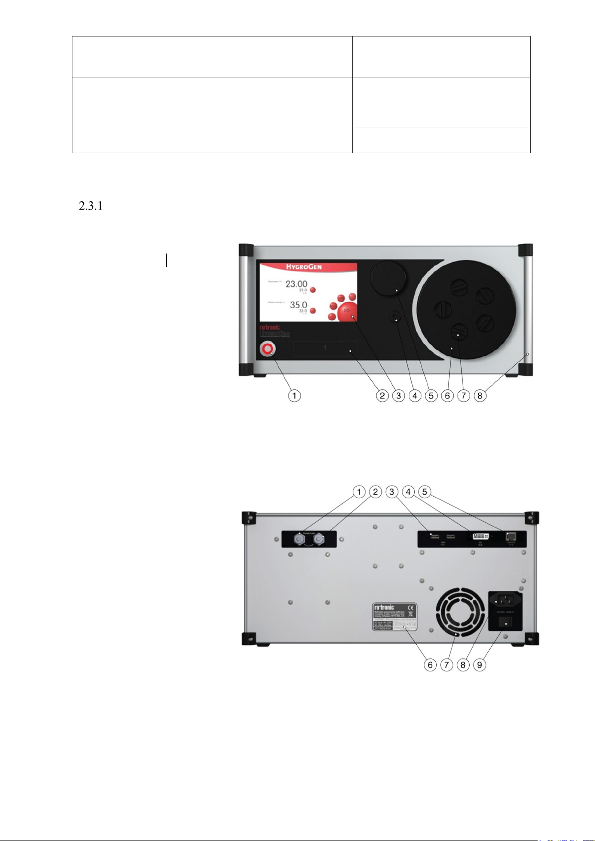
Figure 1: Front of HygroGen2-S
Figure 2: Rear of HygroGen2-S
Document code Unit
HygroGen2: Humidity and Temperature Generator
with AutoCal, Chilled Mirror External Reference, Remote
Screen Share, RemoteAPI and Range Extension options.
2.3 HygroGen2 Assembly
HG2-S
1) Power switch
2) USB ports (7) (8
3) Touch screen controller
4) Water port
5) Desiccant cell
6) Chamber door
7) Probe aperture bung
8) Handle
1) Sample loop return
2) Sample loop outlet
3) USB ports (2)
4) DVI monitor interface
5) Ethernet socket
6) Type label
7) Fan outlet
8) Electrical mains connection
9) Power switch
Page 11 of 101
© 2020; Rotronic AG E-M-HG2-S-XL-V3.4
Page 13

E-M-HG2-S-XL-V3.4
Rotronic AG
Bassersdorf, Switzerland
Instruction Manual
Instruction Manual for Software
Version 3.4
Document Type
Document title
Document code Unit
HygroGen2: Humidity and Temperature Generator
with AutoCal, Chilled Mirror External Reference, Remote
Screen Share, RemoteAPI and Range Extension options.
Page 12 of 101
i. HygroGen2-S Doors
The HygroGen2-S does not come supplied with a door. There are various standard and
customized versions available, depending on the intended use for the instrument, the use of an
external reference (see Appendix A1.2) and the instruments under test. Figure 1(6) above
shows the 15 mm 5-port version (part code: HG2-D-11111). Other options are listed in
Appendix B4.
To access the HygroGen2 chamber, remove the door. Grip firmly and twist the door anticlockwise. In the event that this proves difficult, cool the chamber first. Occasional instrument
application of Krytox grease around the door “O” ring seal will ease movement.
Replacement can be in any position and requires only a gentle clockwise twist.
Before using your HygroGen2, make sure that the door is secured and that all probe apertures
not in use are sealed with a bung (see Figure 2(7) above) or an appropriate alternative seal.
ii. Desiccant Cell
The unit should be supplied with the desiccant cell in place (see Figure 1(5) above). For further
details and best practice for desiccant handling, please see section 8.2.
iii. External Sample Loop
Unless an external sampling system is to be used
(see “External Sample Loop Operation” in Appendix A1.3),
ensure the sample loop caps (Figure 2(1) and (2) above) are firmly secured.
iv. HC2-S Control Probe
The HygroGen2 chamber conditions are monitored and controlled by a ROTRONIC HC2-S or
HC2A-S RH and temperature probe. Depending on the circumstances and whether external
references are being used (see Appendix A1.2 External RH Probe Reference), this probe may
need to be removed for regular calibration.
See Section 8.1.1 for details on removing the control HC2-S probe.
Note: For speed of response, this probe must be employed without a protective filter.
© 2020; Rotronic AG E-M-HG2-S-XL-V3.4
Page 14
E-M-HG2-S-XL-V3.4
Rotronic AG
Bassersdorf, Switzerland
Instruction Manual
Instruction Manual for Software
Version 3.4
Document Type
Document title
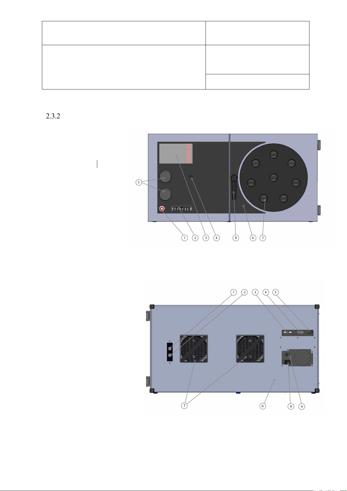
Figure 3: Front of HygroGen2-XL
Figure 4: Rear of HygroGen2-XL
Document code Unit
HygroGen2: Humidity and Temperature Generator
with AutoCal, Chilled Mirror External Reference, Remote
Screen Share, RemoteAPI and Range Extension options.
HygroGen2-XL
1) Power switch
2) USB ports (7) (7)
3) Touch screen controller
4) Water port
5) Desiccant cell
6) Chamber door
7) Probe aperture bung
8) Chamber door handle
1) Sample loop return
2) Sample loop outlet
3) USB ports (2)
4) DVI monitor interface
5) Ethernet socket
6) Type label
7) Fan inlets and filter covers
8) Electrical mains connection
9) Power switch
Page 13 of 101
© 2020; Rotronic AG E-M-HG2-S-XL-V3.4
Page 15
E-M-HG2-S-XL-V3.4
Rotronic AG
Bassersdorf, Switzerland
Instruction Manual
Instruction Manual for Software
Version 3.4
Document Type
Document title
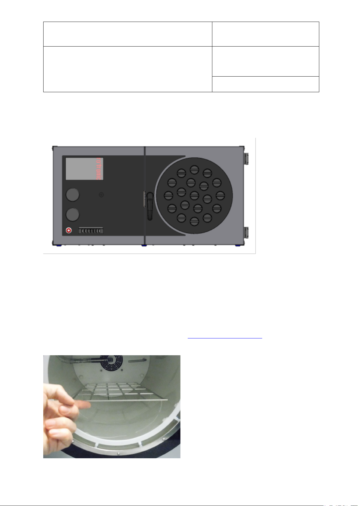
Figure 5: HygroGen2-XL with 19 x 30mm ports
Document code Unit
HygroGen2: Humidity and Temperature Generator
with AutoCal, Chilled Mirror External Reference, Remote
Screen Share, RemoteAPI and Range Extension options.
Page 14 of 101
i. HygroGen2-XL Door
The HygroGen2-XL is supplied with a door, though customised versions are available. At the
time of preparing this manual, the standard configuration has 8 x 30 mm ports; there is also a
19 x 30 mm port version available.
Before using your HygroGen2, make sure that the door is secured and that all probe apertures
not in use are sealed with a bung or an appropriate alternative seal.
ii. HygroGen2-XL Shelves
The HygroGen2-XL has three removable shelves, which secure into clips at the front and back
of the chamber. Early serial number HygroGen2-XL do not have front clips. These can be
retrofitted to improve shelf stability. Please email [email protected] to request front
clips.
© 2020; Rotronic AG E-M-HG2-S-XL-V3.4
Page 16
E-M-HG2-S-XL-V3.4
Rotronic AG
Bassersdorf, Switzerland
Instruction Manual
Instruction Manual for Software
Version 3.4
Document Type
Document title
Figure 6: HygroGen2-XL shelving system
Figure 7: HygroGen2-XL cable management through chamber door
Document code Unit
HygroGen2: Humidity and Temperature Generator
with AutoCal, Chilled Mirror External Reference, Remote
Screen Share, RemoteAPI and Range Extension options.
Page 15 of 101
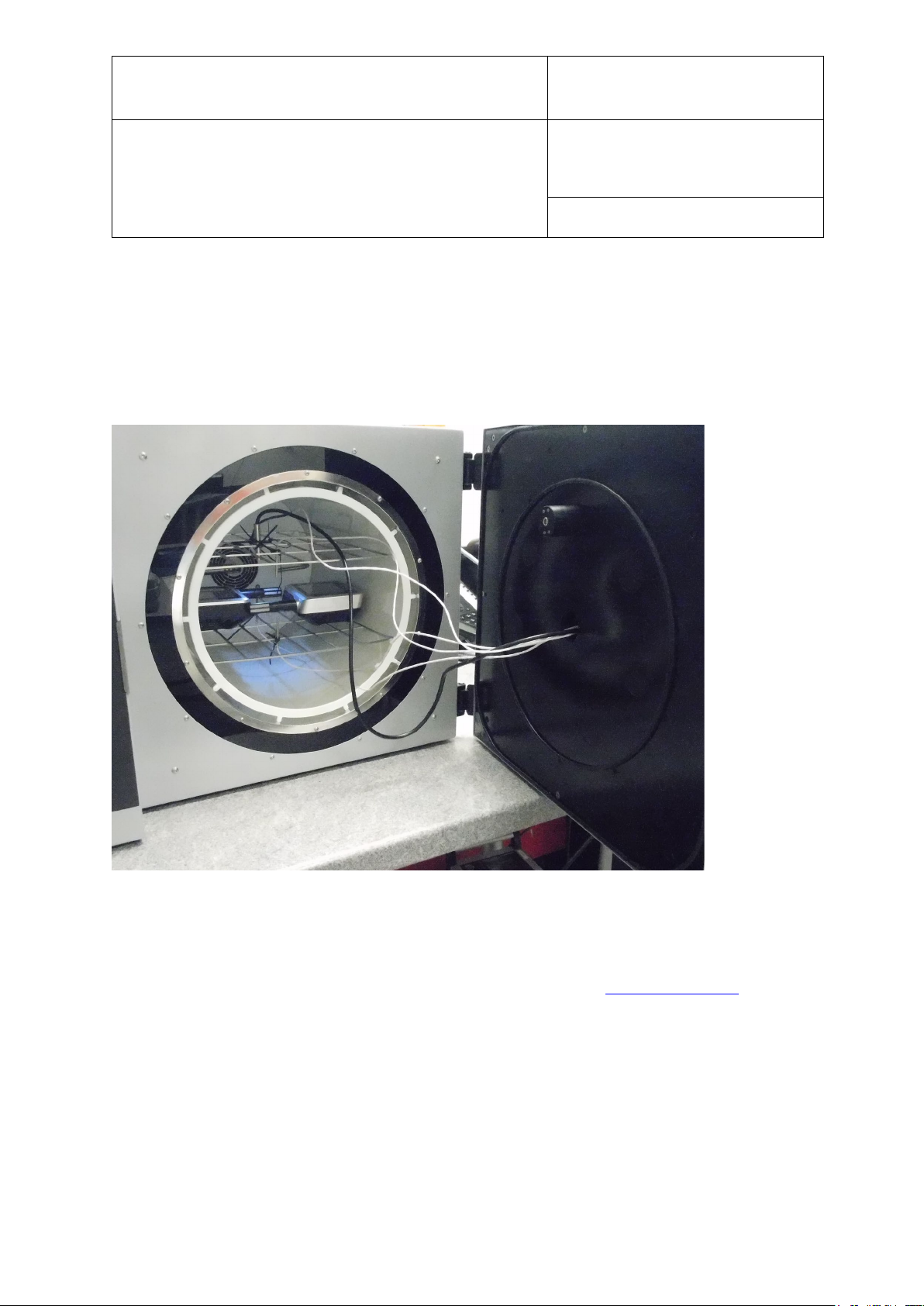
iii. HygroGen2-XL Cable Management
For devices placed wholly inside the chamber, it is recommended to secure cables to the
shelves using cable-ties and run the cables through a spare port in the door. The port can be
sealed using either a cable-gland bung, e.g. HG2-B8-L or some other appropriate
sealing/insulation.
iv. Desiccant Cells
The HygroGen2-XL is supplied with two desiccant cells in place (Figure 3(5) above). The
instrument will use the top desiccant cell by default and automatically switch over to using the
bottom one, should the top one need recharging. The instrument will display “Desiccant Low”
and the desiccant cell can removed and recharged. Should it be left, and the bottom one
become equally run down, the instrument will continuously switch between the two cells; the
drying function will be impaired until at least one is recharged. The desiccant cell currently in
use is displayed on the Settings screen on the desiccant level indicator.
© 2020; Rotronic AG E-M-HG2-S-XL-V3.4
Page 17

E-M-HG2-S-XL-V3.4
Rotronic AG
Bassersdorf, Switzerland
Instruction Manual
Instruction Manual for Software
Version 3.4
Document Type
Document title
Document code Unit
HygroGen2: Humidity and Temperature Generator
with AutoCal, Chilled Mirror External Reference, Remote
Screen Share, RemoteAPI and Range Extension options.
Page 16 of 101
Please note the desiccant indicator will only give a meaningful reading after it has been running
for more than -15% power for more than a minute through a particular cell. For further details
and best practice for desiccant handling, please see section 8.2.
v. External Sample Loop
Unless an external sampling system is to be used (see “External Sample Loop Operation” in
Appendix A1.3), ensure the sample loop caps (Figure 2(1) and (2) above) are firmly secured.
vi. HC2-S Control Probe
The HygroGen2 chamber conditions are monitored and controlled by a ROTRONIC HC2-S or
HC2A-S and temperature probe. Depending on the circumstances and whether external
references are being used (see Appendix A1.2 External RH Probe Reference), this probe may
need to be removed for regular calibration.
See Section 8.1.2 for details on removing the control HC2-S.
Note: For speed of response, this probe must be employed without protective filters.
© 2020; Rotronic AG E-M-HG2-S-XL-V3.4
Page 18
E-M-HG2-S-XL-V3.4
Rotronic AG
Bassersdorf, Switzerland
Instruction Manual
Instruction Manual for Software
Version 3.4
Document Type
Document title
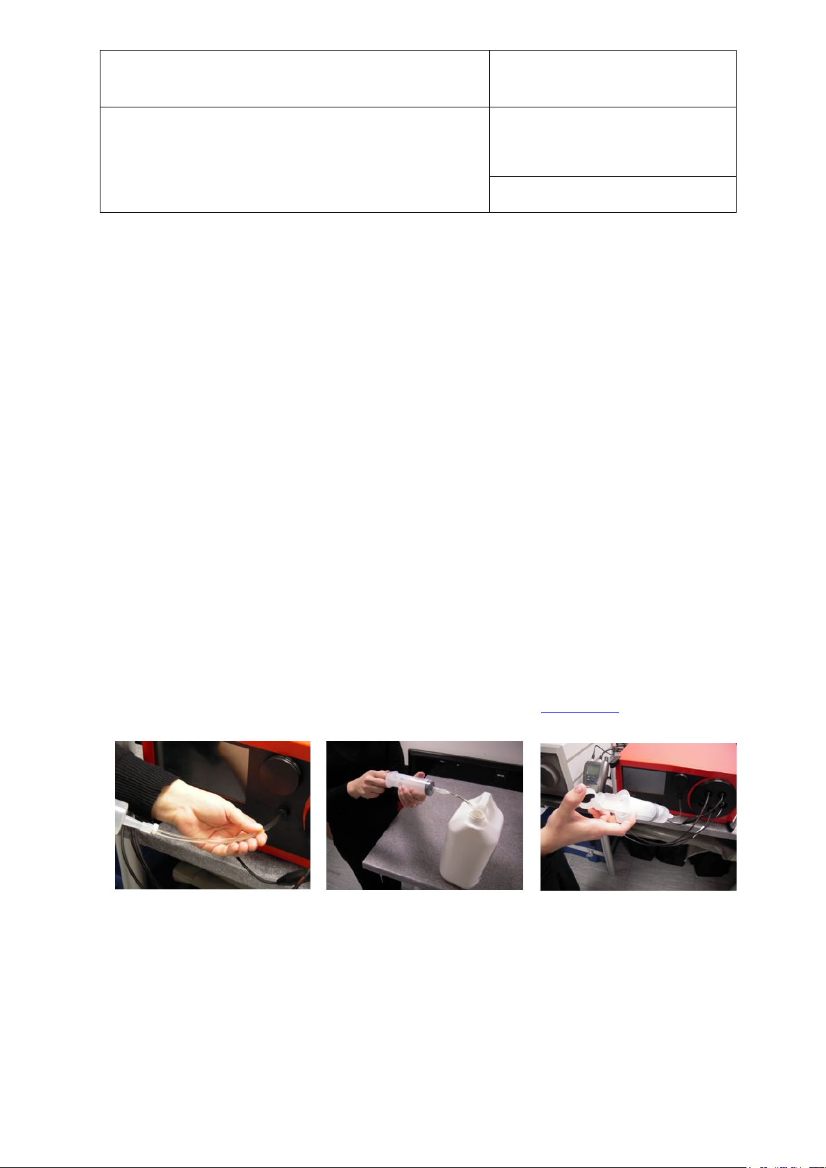
Figure 8: How to fill and empty the Water Reservoir
Document code Unit
HygroGen2: Humidity and Temperature Generator
with AutoCal, Chilled Mirror External Reference, Remote
Screen Share, RemoteAPI and Range Extension options.
Page 17 of 101
2.4 Water Reservoir
The HygroGen2 requires 50-80 ml of demineralised water in the internal reservoir.
Either reverse osmosis (RO) or de-ionised water is recommended. It is NOT recommended to
use distilled water as this readily absorbs atmospheric CO2 to form carbonic acid which can
corrode components within the humidifier.
Insufficient water will deactivate the humidification system. As long as extreme care is taken
not to overfill the water reservoir, the HygroGen2 may be filled and emptied either with the
unit powered up or shut down.
i. To fill the HygroGen2:
a. Insert the tube of the dosing syringe, with the plunger fully depressed, 10 mm into the water
port and extract any residual water by drawing out the plunger.
b. Depress the collar on the water port (Figure 1(4) above) and remove the dosing syringe tube.
Wipe up any spilt water with an absorbent cloth immediately.
c. Fill the dosing syringe with 80 ml of demineralised water. Insert the end of the dosing syringe
tube firmly back into the water port and discharge the syringe steadily. (If water leaks during
this operation the filler tube is not correctly inserted in the water port.)
d. Depress the collar on the water port to remove the dosing syringe tube. Wipe up any spilt
water with an absorbent cloth immediately.
e. A water level indicator is shown in the Settings Screen (see section 3.4.5).
Caution: Do not overfill the HygroGen2
Overfilling of the unit will result in poor humidification and, in extreme cases, water may be
pumped into the chamber. If the HygroGen2 is overfilled, the humidifier should be fully
emptied and then refilled with 50-80 ml of water (as described above). If there is water present
in the chamber of the HygroGen2, this should be removed using an absorbent cloth. Ensure the
© 2020; Rotronic AG E-M-HG2-S-XL-V3.4
Page 19
E-M-HG2-S-XL-V3.4
Rotronic AG
Bassersdorf, Switzerland
Instruction Manual
Instruction Manual for Software
Version 3.4
Document Type
Document title
Document code Unit
HygroGen2: Humidity and Temperature Generator
with AutoCal, Chilled Mirror External Reference, Remote
Screen Share, RemoteAPI and Range Extension options.
Page 18 of 101
HygroGen2 is switched off and the mains power unplugged before manually drying the
chamber.
ii. To empty the HygroGen2:
a. Insert the tube of the dosing syringe, with the plunger fully depressed, 10 mm into the water
port and extract any water by drawing out the plunger.
b. Depress the collar on the water port to remove the dosing syringe tube. Wipe up any spilt
water with an absorbent cloth immediately.
c. Water discharged from the HygroGen2 may be stored safely and reused at a later date.
Note: The HygroGen2 should always be emptied if it is being shipped or stored (see
section 5.3 Preparing the Unit for Transit or Storage). This will prevent ingress of water
into the chamber should the unit be inverted and prevent possible frost damage.
iii. Ultra-violet sterilisation lamp
As a precaution against any microbial and algae water contamination, HygroGen2 incorporates
an Ultraviolet (UV) sterilisation lamp within the water reservoir. No user intervention is
required - HygroGen2 auto-cycles the process.
Under no circumstance should the water reservoir be opened by non-qualified personnel.
Direct exposure to UV lamps can cause burns or blindness.
© 2020; Rotronic AG E-M-HG2-S-XL-V3.4
Page 20

E-M-HG2-S-XL-V3.4
Rotronic AG
Bassersdorf, Switzerland
Instruction Manual
Instruction Manual for Software
Version 3.4
Document Type
Document title
Document code Unit
HygroGen2: Humidity and Temperature Generator
with AutoCal, Chilled Mirror External Reference, Remote
Screen Share, RemoteAPI and Range Extension options.
Page 19 of 101
3 HygroGen2 - Basic Operation
This applies to all HygroGen2 models. For details on the operation of optional Enhanced
Features, see section 4.
3.1 Switching On
a. Ensure the electrical mains supply is correctly plugged in and switched on.
b. Switch the unit on by pressing the Power Switch (see Figure 1(1) above) once.
c. The fans within the unit will switch on giving an immediate audible indication the unit is
powered.
d. The controller will power up and display the controller home screen (as shown in Figure 12).
On power up:
The temperature and humidity set-points default to the last set values.
The temperature and humidity control defaults to the last set condition.
If the “Low Water Level” alarm is displayed, then the unit should be filled as described in
section 2.4. Humidification is disabled until water is filled.
© 2020; Rotronic AG E-M-HG2-S-XL-V3.4
Page 21
E-M-HG2-S-XL-V3.4
Rotronic AG
Bassersdorf, Switzerland
Instruction Manual
Instruction Manual for Software
Version 3.4
Document Type
Document title
Document code Unit
HygroGen2: Humidity and Temperature Generator
with AutoCal, Chilled Mirror External Reference, Remote
Screen Share, RemoteAPI and Range Extension options.
Page 20 of 101
3.2 Upgrading HygroGen2 Firmware
To determine the latest version of the HygroGen2 firmware, please consult the website:
https://support.vct-ltd.co.uk/support/hygrogen2/
https://support.vct-ltd.co.uk/support/hygrogen2-xl/
The firmware version your HygroGen2 is running can be determined via the Settings screen,
selecting the “Support” drop-down menu and choosing “HygoGen2 Information”. For further
details see Section 3.4.7.
Updating HygroGen2 firmware from a version 3.1 or earlier
If upgrading from version prior to 3.3.x a FULL CLEAN INSTALL is required. This will reformat the HG2XL and install the current HG2XL base image and controller firmware version.
Please see separate documentation at the website links above.
Updating HygroGen2 firmware from an earlier version of 3.3.x.x
Either do a FULL CLEAN INSTALL (Section 3.2.1)
Or do a Controller Update (see below) this updates the controller firmware to the current version,
but does not format and re-install the base image.
a. On a PC, download the latest version 3.3.x.x of the HygroGen2 Controller Update firmware via
the website link above.
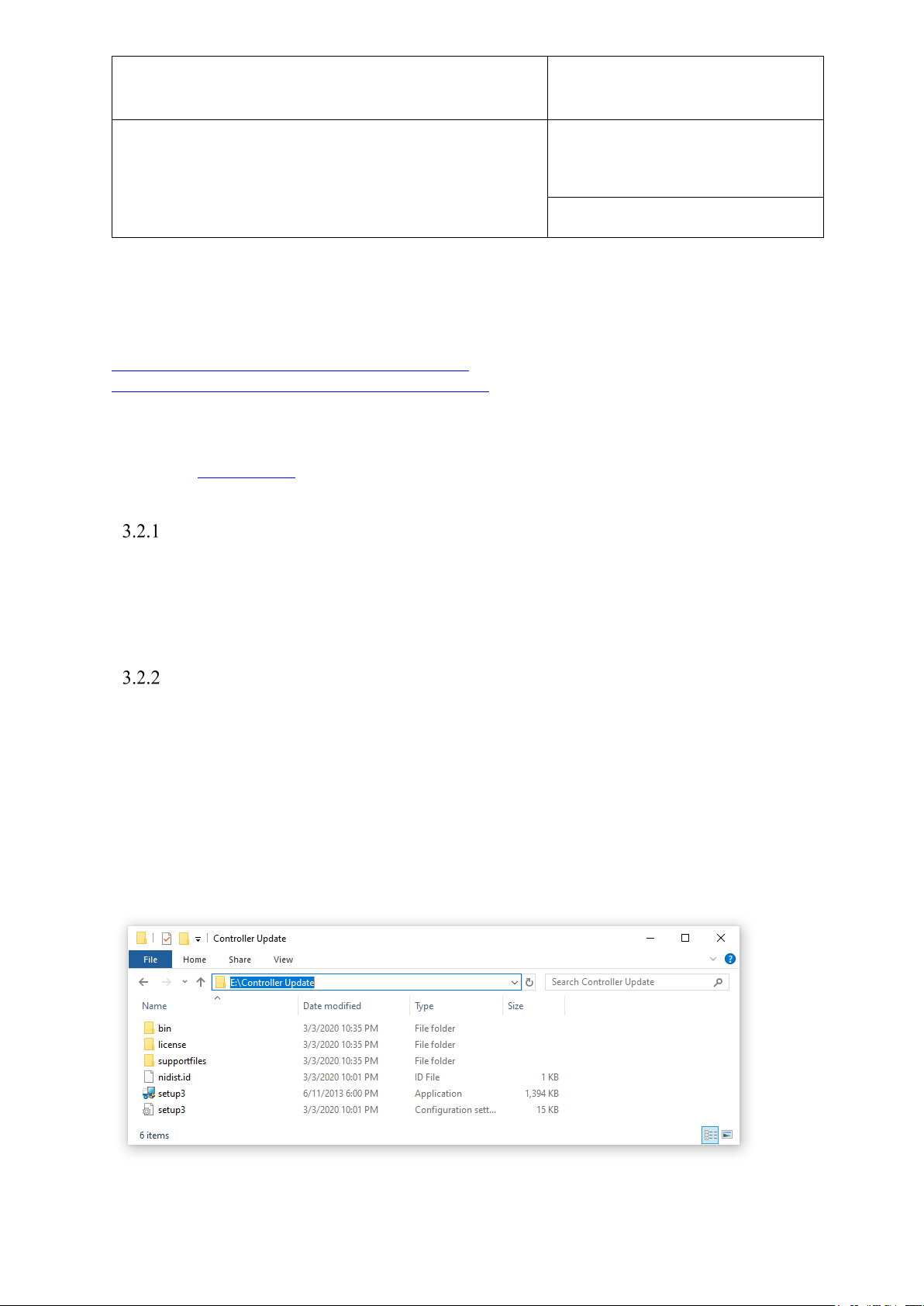
b. Unzip this file to the root of a USB stick.
The file structure should look like this when completed successfully:
© 2020; Rotronic AG E-M-HG2-S-XL-V3.4
Page 22
E-M-HG2-S-XL-V3.4
Rotronic AG
Bassersdorf, Switzerland
Instruction Manual
Instruction Manual for Software
Version 3.4
Document Type
Document title
Document code Unit
HygroGen2: Humidity and Temperature Generator
with AutoCal, Chilled Mirror External Reference, Remote
Screen Share, RemoteAPI and Range Extension options.
Page 21 of 101
Any other file structure, or root director folder name will result in the HygroGen2 not finding the
updater.
c. If HW4 is also to be updated make a note of your HW4 serial number, by launching HW4 and
clicking Registration on the startup screen (see section 6.2 for further details).
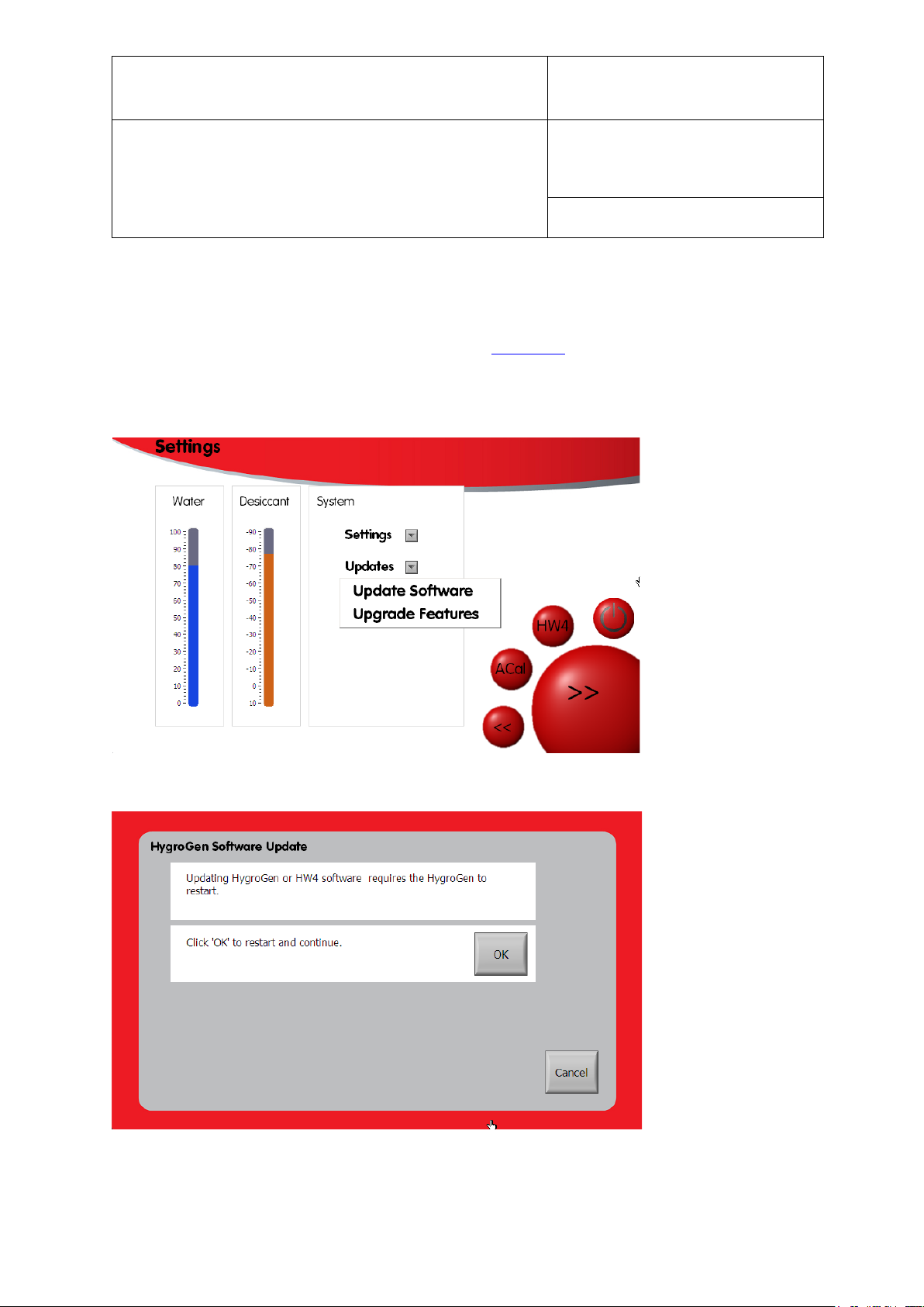
d. Reboot the HygroGen2 into Configuration Mode, by going into the Settings, then select “Update
Software” from the “Updates” drop-down menu.
e. Click OK to reboot the HG2 into configuration mode.
f. Insert the USB stick into any port in the HygroGen2.
© 2020; Rotronic AG E-M-HG2-S-XL-V3.4
Page 23
E-M-HG2-S-XL-V3.4
Rotronic AG
Bassersdorf, Switzerland
Instruction Manual
Instruction Manual for Software
Version 3.4
Document Type
Document title
Document code Unit
HygroGen2: Humidity and Temperature Generator
with AutoCal, Chilled Mirror External Reference, Remote
Screen Share, RemoteAPI and Range Extension options.
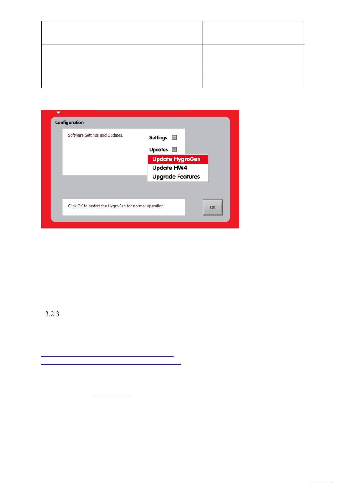
g. Select “Update HygroGen“ from the “Updates“ drop-down menu.
Page 22 of 101
h. The sceen will go black and an installation interface appear. Follow the on screen instructions,
and agree to the terms and conditions.
i. At the end of the process, click Next and the HygroGen2 Configuration Mode page will
reappear after a few seconds.
j. Click OK to reboot into Operational Mode or continue below to update the built-in HW4
software.
Updating HW4 version
To determine the latest version available of the HygroGen2 built-in HW4 software, please
consult the ROTRONIC website:
https://support.vct-ltd.co.uk/support/hygrogen2/
https://support.vct-ltd.co.uk/support/hygrogen2-xl/
The HW4 software version your HygroGen2 is running can be determined via the Settings
screen, selecting the “Support” drop-down menu and choosing “HygoGen2 Information”. For
further details see Section 3.4.7.
Please ensure the HygroGen2 is running the latest version of the firmware before updating
HW4 (see section above).
© 2020; Rotronic AG E-M-HG2-S-XL-V3.4
Page 24
E-M-HG2-S-XL-V3.4
Rotronic AG
Bassersdorf, Switzerland
Instruction Manual
Instruction Manual for Software
Version 3.4
Document Type
Document title
Document code Unit
HygroGen2: Humidity and Temperature Generator
with AutoCal, Chilled Mirror External Reference, Remote
Screen Share, RemoteAPI and Range Extension options.
Page 23 of 101
a. If you have not already made a note of your HW4 serial key, please ensure you are in Operational
Mode and launch HW4, and then identify the key selecting ‘Registration’ from the startup screen
(see section 6.2 for further details).
b. On a PC, download the latest version of HW4 from the website above
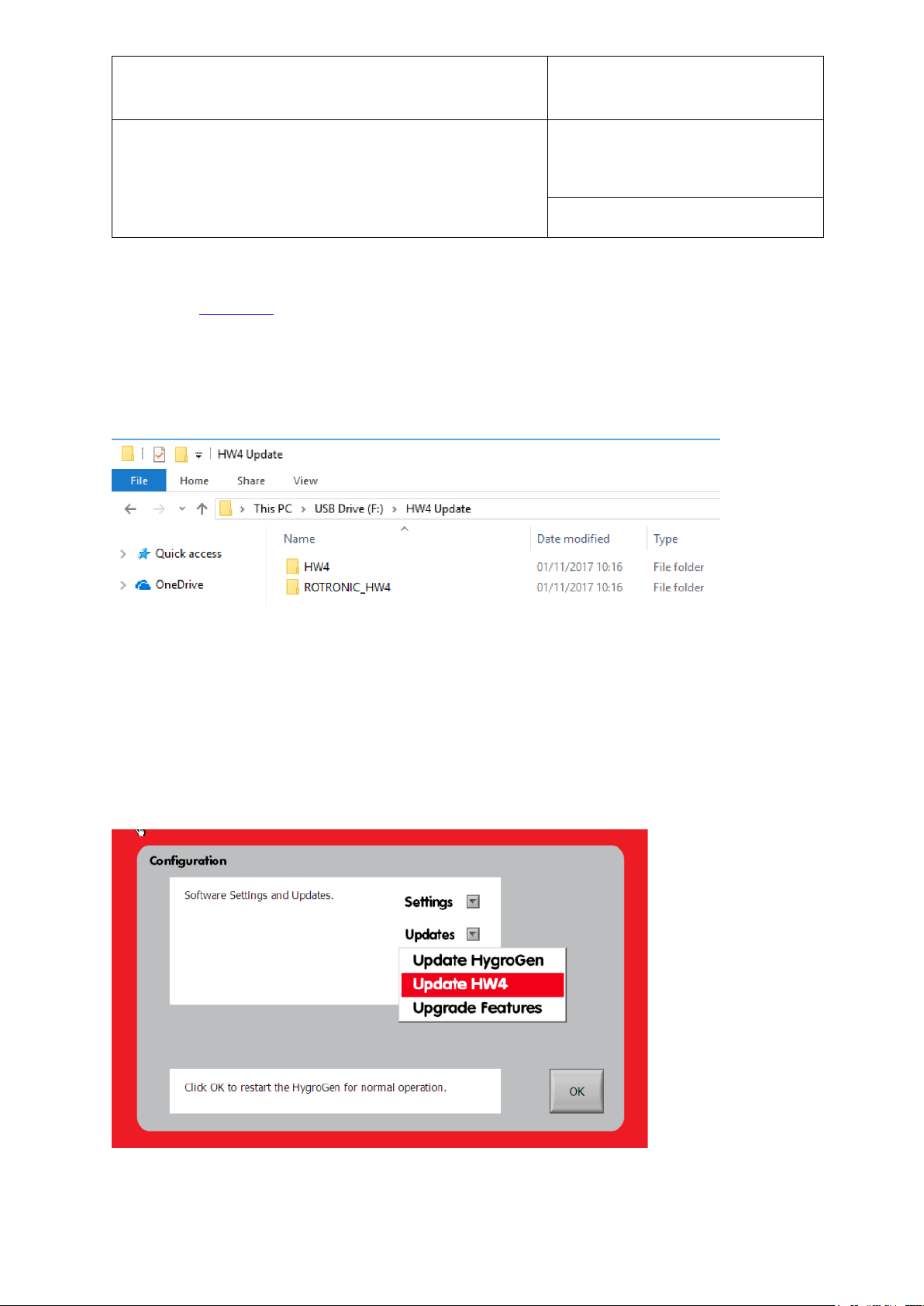
c. Unzip this file to the root of the same USB stick. The file structure should look like this when
completed successfully:
It is essential the folder in the root director is called “HW4 Update”.
d. Safely eject the USB stick from the PC.
e. On the HygroGen2, if not already in Configuration Mode, go to the Settings Page and select
“Update Software” from the “Updates” drop-down menu. Press OK and the HygroGen2 will
reboot into Configuration Mode.
f. Select Updates and then Update HW4.
© 2020; Rotronic AG E-M-HG2-S-XL-V3.4
Page 25
E-M-HG2-S-XL-V3.4
Rotronic AG
Bassersdorf, Switzerland
Instruction Manual
Instruction Manual for Software
Version 3.4
Document Type
Document title
Document code Unit
HygroGen2: Humidity and Temperature Generator
with AutoCal, Chilled Mirror External Reference, Remote
Screen Share, RemoteAPI and Range Extension options.
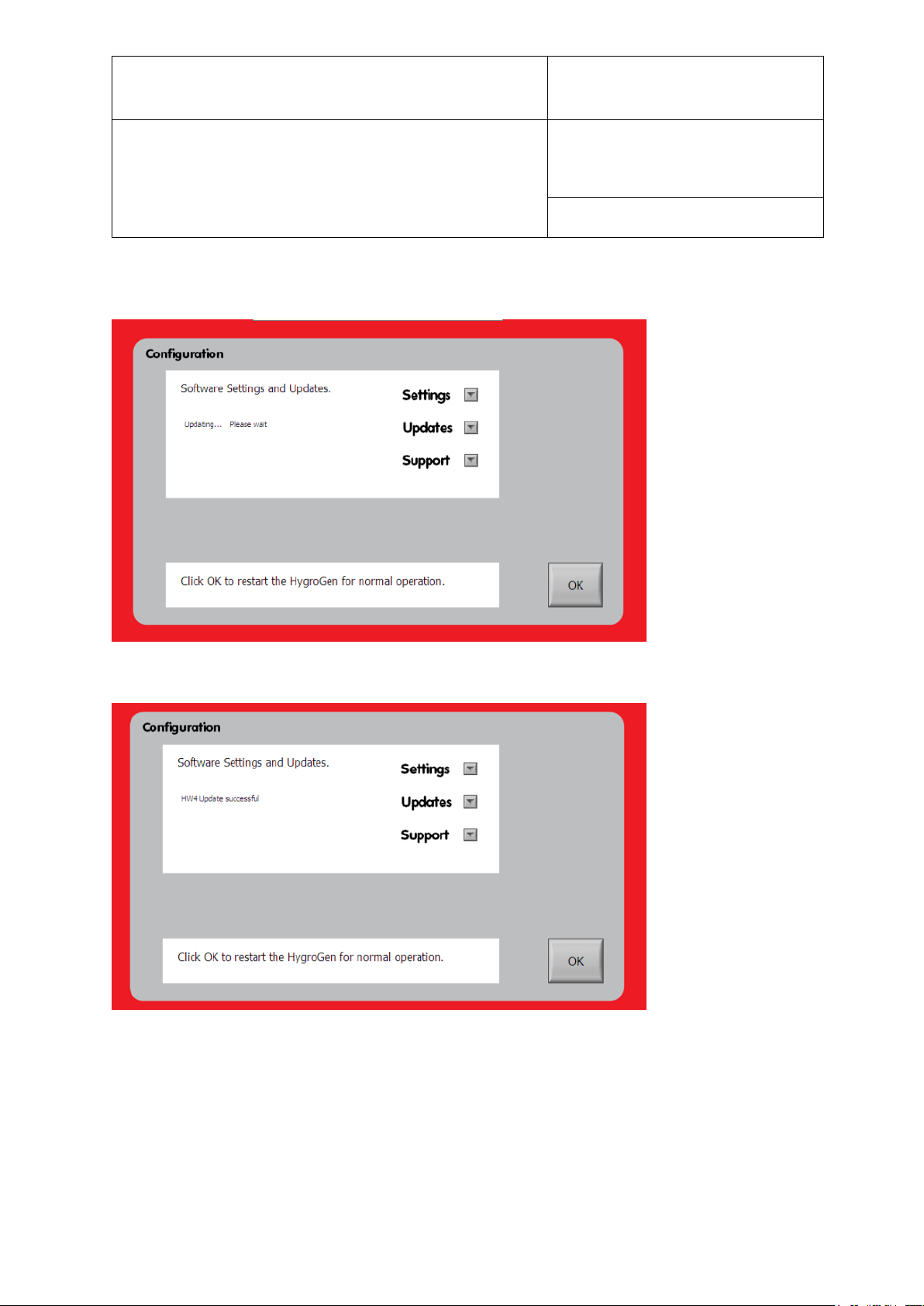
g. Observe the on-screen progress
Page 24 of 101
h. When complete, the HG2 will report HW4 Update Succesful.
i. Click OK to reboot.
j. The HygroGen2 will return to standard mode. Start HW4 and re-enter the registration code
recorded previously to enable full operation.
© 2020; Rotronic AG E-M-HG2-S-XL-V3.4
Page 26
E-M-HG2-S-XL-V3.4
Rotronic AG
Bassersdorf, Switzerland
Instruction Manual
Instruction Manual for Software
Version 3.4
Document Type
Document title
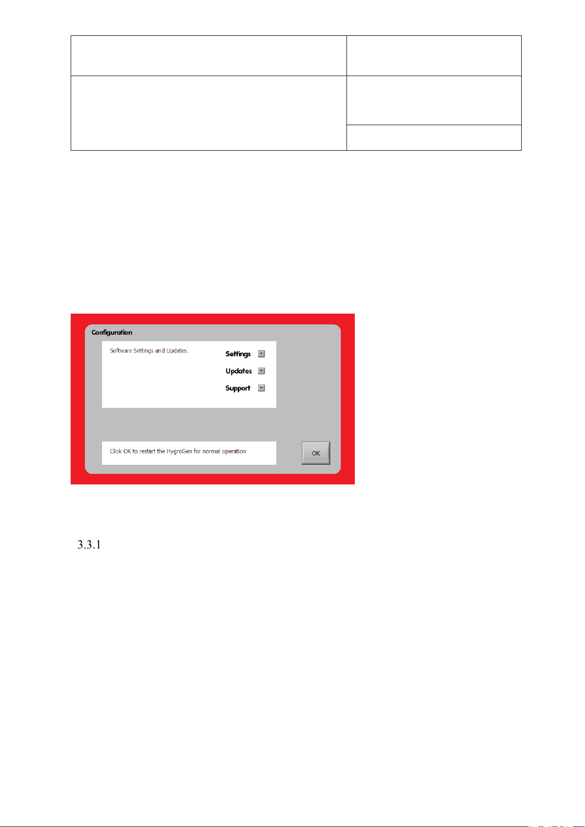
Figure 9: Configuration Mode
Document code Unit
HygroGen2: Humidity and Temperature Generator
with AutoCal, Chilled Mirror External Reference, Remote
Screen Share, RemoteAPI and Range Extension options.
Page 25 of 101
3.3 Configuration Mode Settings
Certain settings on the HygroGen2 must be made in Configuration Mode. From Standard
Operation Mode, go to the Settings screen, then the “Settings” drop-down menu and select
either “Network”, “Date and Time”, “Touchscreen”, or “Update Software”. All four options
effectively do the same thing (i.e. reboot the HygroGen2 into Configuration Mode); press
“OK” to restart the HygroGen2.
Network Settings
Prior to machine serial number VCT-HG2-1281, the network port on the back of the
HygroGen2 was physically disabled. Since this unit, and for every unit that has received a
service since January 2013, the network port has been physically enabled, but its functionality
has been disabled in software.
As of v2.1, there is an option to enable the functionality, which is required for the Remote
Control/Support Enhanced Feature. If you do not intend to use the Remote features, the
Network functionality can still be enabled, to no disadvantage, but some organisations may
stipulate it is turned off before the instrument can be used.
© 2020; Rotronic AG E-M-HG2-S-XL-V3.4
Page 27
E-M-HG2-S-XL-V3.4
Rotronic AG
Bassersdorf, Switzerland
Instruction Manual
Instruction Manual for Software
Version 3.4
Document Type
Document title
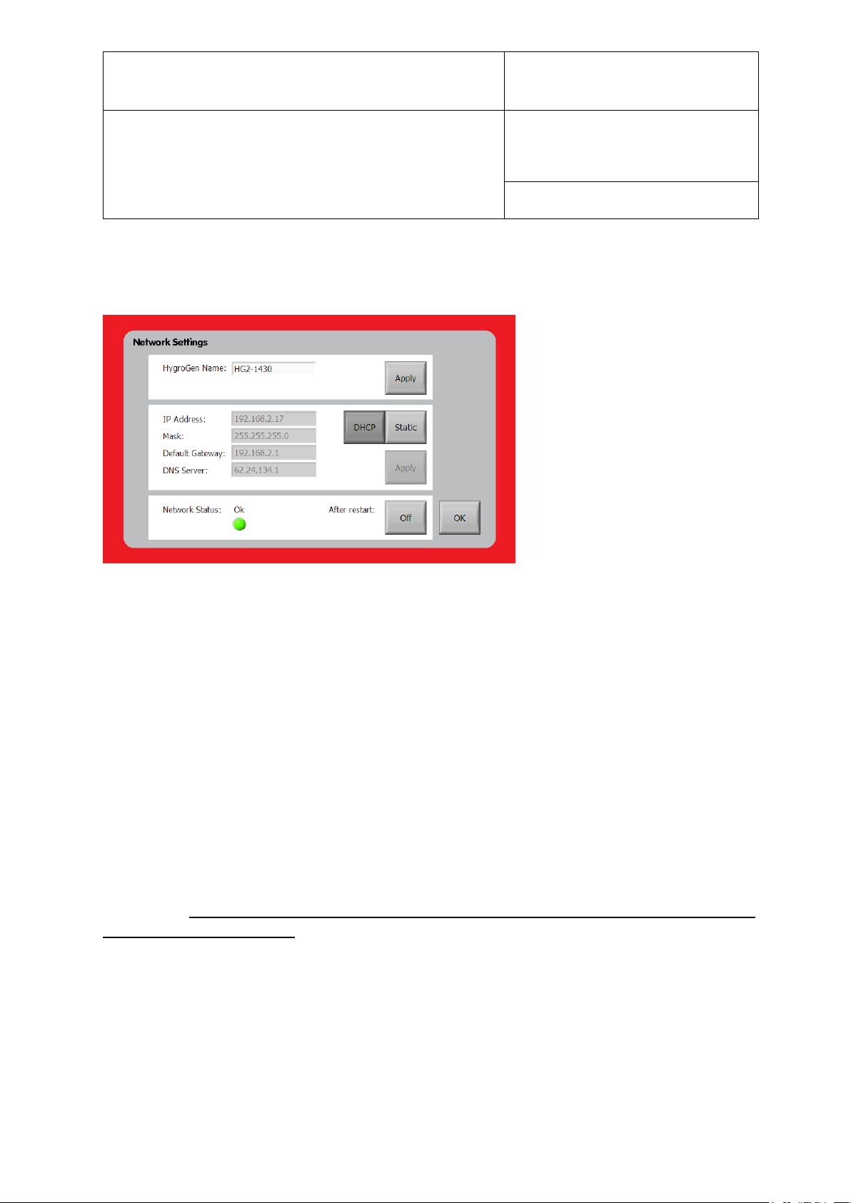
Figure 10: Network Settings
Document code Unit
HygroGen2: Humidity and Temperature Generator
with AutoCal, Chilled Mirror External Reference, Remote
Screen Share, RemoteAPI and Range Extension options.
Page 26 of 101
By default, when v2.1 is installed, the network port functionality is disabled. To enable it,
select “Network” from the “Settings” drop-down menu from within the Configuration Mode
“Settings and Updates” screen.
To turn on the functionality, press the “After restart” button so that it shows “On”. Review and
accept the legal disclaimer that pops up in order to continue. Press OK to go back to the
“Settings and Updates” screen and then press OK to restart. The instrument will restart back
into Configuration Mode to complete the next step. When rebooted, please reselect “Network”
via the “Settings” drop-down menu.
Plug the HygroGen2 into your network using a standard RJ-45 Ethernet cable. If network
functionality is not configured, “Network Status” will show as “down”. If it is configured, and
assuming the network cable is attached to other networking hardware, it will show as “OK”,
otherwise it will show as “unplugged”.
PLEASE note: if your instrument has serial number VCT-HG2-1280 or earlier and has
NOT been serviced since January 2013, your instrument requires a physical modification.
Please contact your ROTRONIC distributor who will arrange for this operation to be
performed. Without this modification, the Network Status will show as “unplugged” even
if it is plugged in correctly. Please also note, physical modifications made by anyone other
than Authorised Service Centres will void the HygroGen2 warranty.
With the HygroGen2 plugged into a network, IP settings need to be configured. Networking
addressing can be set to obtain an address automatically via DHCP, if your network supports it,
or manually via “Static”. Please contact your local IT administrator for advice, if unsure. You
may be required to advise the network hardware (MAC) address of the instrument. This can be
found in the “HygroGen2 Info” via the “Support” drop-down menu.
© 2020; Rotronic AG E-M-HG2-S-XL-V3.4
Page 28
E-M-HG2-S-XL-V3.4
Rotronic AG
Bassersdorf, Switzerland
Instruction Manual
Instruction Manual for Software
Version 3.4
Document Type
Document title
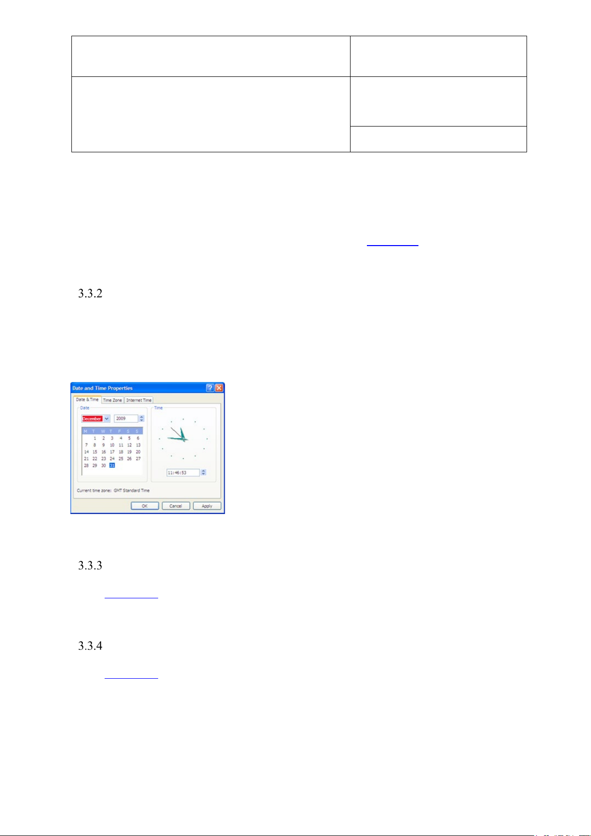
Figure 11: Date and Time Properties
Document code Unit
HygroGen2: Humidity and Temperature Generator
with AutoCal, Chilled Mirror External Reference, Remote
Screen Share, RemoteAPI and Range Extension options.
Page 27 of 101
The IP address assigned to your instrument will be reported in the Network Settings interface
and via the “HygroGen2 Info” screen. The HygroGen2 will assign itself a network
name/identity. This can be changed within the interface. It is recommended to change it to the
instrument’s serial number, though local network policies may require something else.
Operation of the Remote Control functionality is described in section 4.3.
Date and Time Settings
Date and time stamps are included in AutoCal and HW4 logged data.
To adjust these settings, select the “Date and Time” option from the “Settings” drop-down
menu on the “Settings and Updates” screen.
International Keyboard
Please Section 7.1 for details about configuring external input peripherals. NB Configuration
mode is not required to alter this setting.
External Monitor
Please Section 7.2 for details about configuring external output peripherals. NB Configuration
mode is not required to alter this setting.
© 2020; Rotronic AG E-M-HG2-S-XL-V3.4
Page 29

E-M-HG2-S-XL-V3.4
Rotronic AG
Bassersdorf, Switzerland
Instruction Manual
Instruction Manual for Software
Version 3.4
Document Type
Document title
Document code Unit
HygroGen2: Humidity and Temperature Generator
with AutoCal, Chilled Mirror External Reference, Remote
Screen Share, RemoteAPI and Range Extension options.
Page 28 of 101
Touch Screen Calibration
The touch screen should be calibrated if the screen is not responding correctly to touch input.
You may wish to plug in a USB mouse to perform this step.
Select the “Touch Screen” option from the “Settings” drop-down menu on the “Settings and
Updates” screen. Pressing the touch screen button will begin a four-point calibration. Press the
cross in each corner of the screen as directed.
© 2020; Rotronic AG E-M-HG2-S-XL-V3.4
Page 30
E-M-HG2-S-XL-V3.4
Rotronic AG
Bassersdorf, Switzerland
Instruction Manual
Instruction Manual for Software
Version 3.4
Document Type
Document title
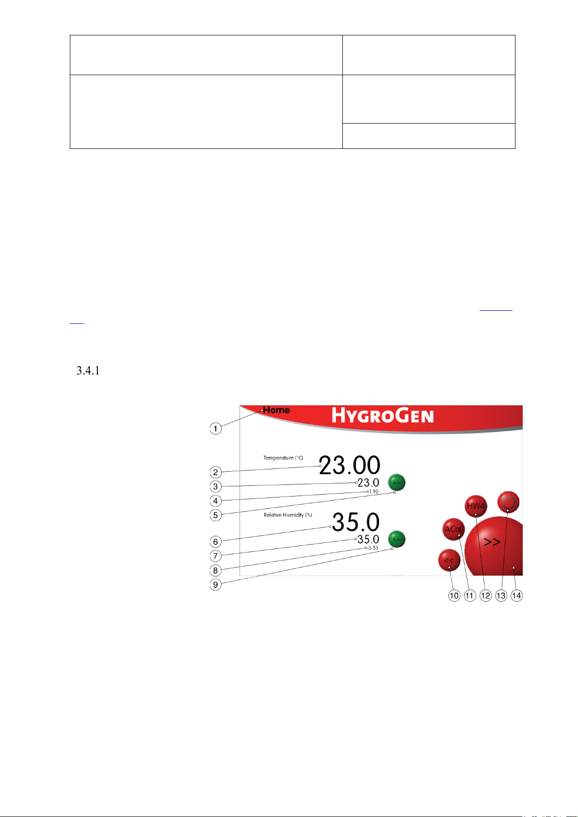
Figure 12: HygroGen2 Home Screen
Document code Unit
HygroGen2: Humidity and Temperature Generator
with AutoCal, Chilled Mirror External Reference, Remote
Screen Share, RemoteAPI and Range Extension options.
Page 29 of 101
3.4 HygroGen2 Touchscreen Interface
The HygroGen2 controller consists of four top level screens that are accessed using the forward
or back buttons in a loop:
Please note: the Programmer Screen is replaced by the AutoCal Screen when AutoCal is
activated. The standard Programmer functionality is still available, however. Please see section
4.1 for more details.
Controller Home Screen
1) Menu (drop down)
2) Chamber temperature
3) Temperature set-point
4) Heating power
5) Temperature control
6) Chamber humidity
7) Humidity set-point
8) Humidification power
9) Humidity control
10) Previous screen
11) Prog/ACal function
12) HW4 software
13) Power off
14) Next screen
i. Navigation (items 1, 10 & 14)
The user can navigate to different screens using the drop-down menu (item 1) or can scroll
through the four main screens using items 10 & 11.
© 2020; Rotronic AG E-M-HG2-S-XL-V3.4
Page 31

E-M-HG2-S-XL-V3.4
Rotronic AG
Bassersdorf, Switzerland
Instruction Manual
Instruction Manual for Software
Version 3.4
Document Type
Document title
Document code Unit
HygroGen2: Humidity and Temperature Generator
with AutoCal, Chilled Mirror External Reference, Remote
Screen Share, RemoteAPI and Range Extension options.
Page 30 of 101
ii. Temperature and Humidity Set-Points (items 3 & 7)
At any time, the user can change humidity or temperature set-points by simply touching the
set-point on the screen. A pop-up will appear and either the touch screen or, when connected,
the keyboard/mouse may be used to input desired values.
Note: To aid a smooth and efficient transition between temperature set-points, the controller is
programmed to suspend humidification during changes in temperature. Once the chamber
temperature is within 0.7 °C of the temperature set-point, the humidity control is activated.
When set-point combinations are programmed that resolve a low dew point condition (i.e.
0 °C, 5 %rh = -36 °C dew point), make sure that the desiccant is dry enough to achieve the
desired value. Check the desiccant condition on the Settings screen (Figure 16) and consult
maintenance records to establish when the desiccant was last changed. Stabilisation time to low
RH conditions will be longer than normal as the chamber and internal surfaces need to be very
dry.
iii. Temperature and Humidity Control (items 5 & 9)
The temperature and humidity control can be set to automatic or off. Automatic mode results in
the unit attempting to adjust to the temperature (or humidity) in the chamber to match the setpoint value. When switched off the HygroGen2 does not control the parameter.
When off, the control buttons are grey.
When on, but not stable, the control buttons are red.
When on and stable, the control buttons are green.
Temperature indicator is green when the control PT100 temperature sensor (see Appendix A2)
is within 0.01 °C of the set-point and the control temp is within 0.01 °C of the internal (HC2-S)
reference temperature sensor.
RH indicator is green when the RH reference is within 0.1%rh of the set point and the control
RH is within 0.05 %rh of the internal (HC2-S) reference humidity sensor.
© 2020; Rotronic AG E-M-HG2-S-XL-V3.4
Page 32
E-M-HG2-S-XL-V3.4
Rotronic AG
Bassersdorf, Switzerland
Instruction Manual
Instruction Manual for Software
Version 3.4
Document Type
Document title
Figure 13: Trend Screen
Document code Unit
HygroGen2: Humidity and Temperature Generator
with AutoCal, Chilled Mirror External Reference, Remote
Screen Share, RemoteAPI and Range Extension options.
Page 31 of 101
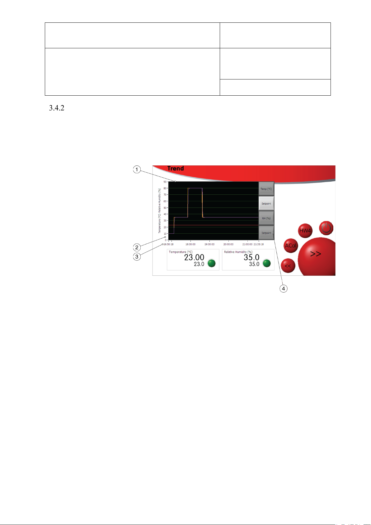
Trend Screen
The Trend Screen shows the instrument’s chamber conditions and the set-points the instrument
is programmed to reach.
1) Trend
2) y-axis
3) Time axis
4) Trace selection
i. Trace selection (item 4)
The traces displayed can be selected using the buttons (item 4)
ii. Trend Axes (items 2 & 3)
The y-axis (item 2) is self-scaling; the x-axis (time) (item 3) can be adjusted by clicking
anywhere along it and typing in the desired timescale.
© 2020; Rotronic AG E-M-HG2-S-XL-V3.4
Page 33
E-M-HG2-S-XL-V3.4
Rotronic AG
Bassersdorf, Switzerland
Instruction Manual
Instruction Manual for Software
Version 3.4
Document Type
Document title
Figure 14: Programmer
Document code Unit
HygroGen2: Humidity and Temperature Generator
with AutoCal, Chilled Mirror External Reference, Remote
Screen Share, RemoteAPI and Range Extension options.
Page 32 of 101
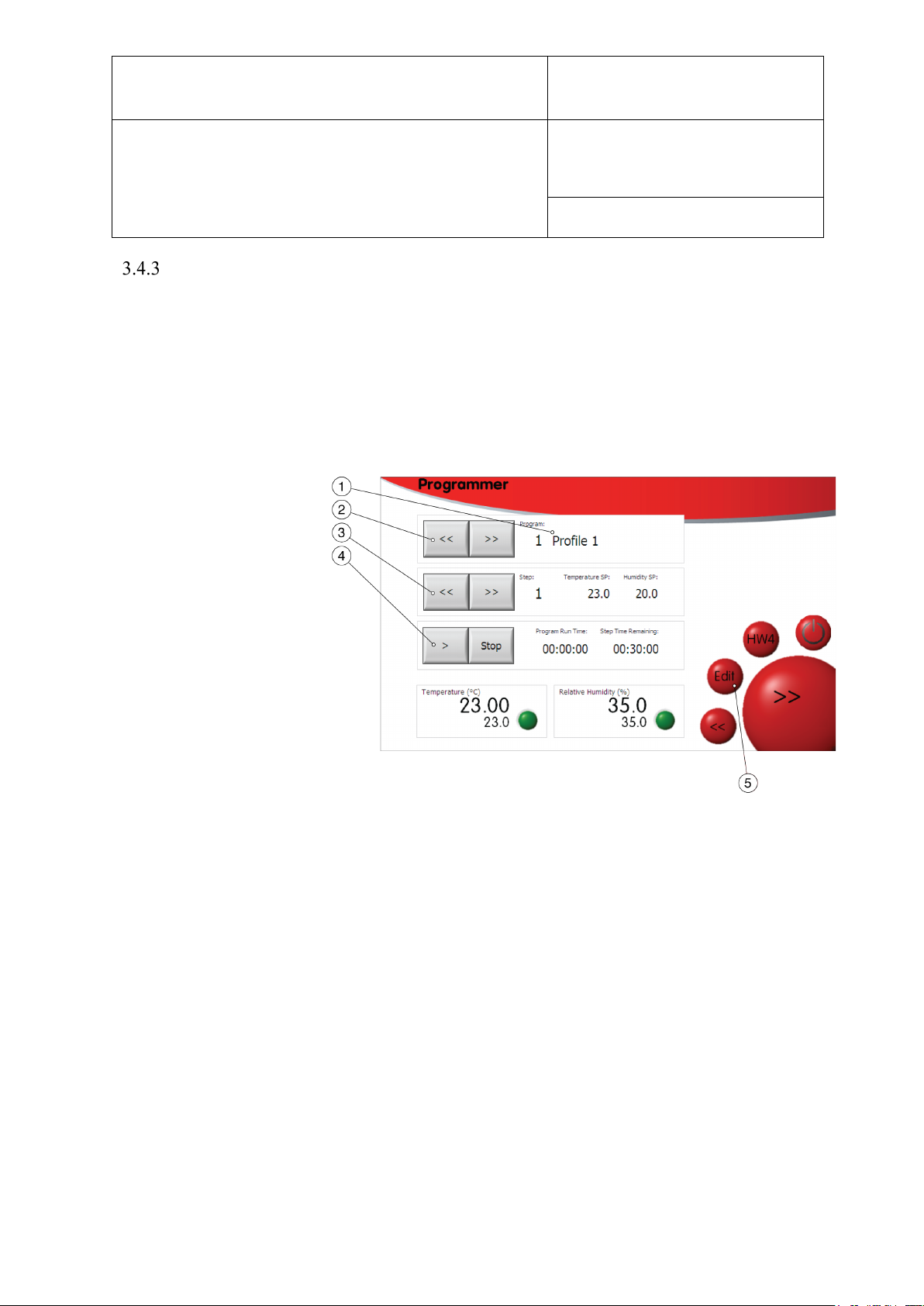
Programmer Screen
The HygroGen2 programmer function enables the user to automate a sequence of RH and/or
temperature set-points. If the AutoCal function is enabled the Programmer function is only
available via the Home menu (Figure 12: item 1).
The HygroGen Programmer function can accommodate 20 programs with up to 200 steps each.
Programs are edited via the Edit Program (Figure 15).
1) Program name & number
2) Program selection
3) Step selection
4) Run/stop program
5) Edit program
i. Program Selection (items 1 & 2)
Item 1 identifies the program number and title. You can use the “<<” and “>>” buttons to
scroll through the saved programs.
ii. Step Selection (item 3)
Use the Step Selection buttons (item 3) to select the program step at which the program will
start. The temperature and humidity set-points (SP) for the selected step are displayed.
iii. Run/Stop (item 4)
Start the selected program running at the selected step using the “>” button. The total time the
program has been running, and the time left on the current step are displayed. Use the Stop
button to halt the program before it has completed.
© 2020; Rotronic AG E-M-HG2-S-XL-V3.4
Page 34
E-M-HG2-S-XL-V3.4
Rotronic AG
Bassersdorf, Switzerland
Instruction Manual
Instruction Manual for Software
Version 3.4
Document Type
Document title
Figure 15: Edit Program
Document code Unit
HygroGen2: Humidity and Temperature Generator
with AutoCal, Chilled Mirror External Reference, Remote
Screen Share, RemoteAPI and Range Extension options.
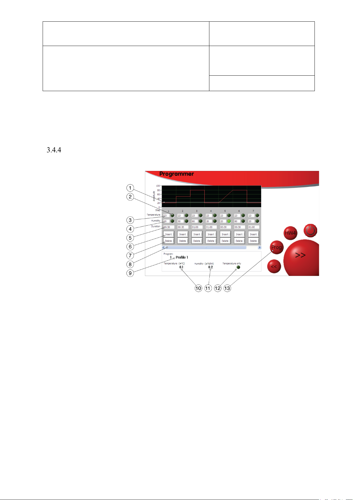
iv. Edit Program (item 5)
Use this button to go to the Edit Program screen (see Figure 15).
Edit Program Screen
1) Graphic indicator
2) Ramp/Soak control
3) Temperature set-point
4) Humidity set-point
5) Step duration
6) Insert step
7) Delete step
8) Scroll to view steps
9) Program
10) Temperature tolerance
11) Humidity tolerance
12) Temperature only
13) Programmer
Page 33 of 101
i. Select a Program to Edit
Either select the desired program to edit on the Programmer Screen and click the Edit button,
or if already in the Edit Program Screen, click on the program number (item 9) and enter the
desired program number.
ii. Edit a Program Name
To edit the program name click on it (item 9) (USB keyboard required).
iii. Edit a Step
Each program comprises at least one step. Each step can be edited. Enter the desired step setpoints and duration (items 3, 4 & 5). A graphical representation of the step is shown to help
visualise the sequence.
© 2020; Rotronic AG E-M-HG2-S-XL-V3.4
Page 35

E-M-HG2-S-XL-V3.4
Rotronic AG
Bassersdorf, Switzerland
Instruction Manual
Instruction Manual for Software
Version 3.4
Document Type
Document title
Document code Unit
HygroGen2: Humidity and Temperature Generator
with AutoCal, Chilled Mirror External Reference, Remote
Screen Share, RemoteAPI and Range Extension options.
Page 34 of 101
iv. Insert or Delete a Step (items 6 & 7)
Use the insert and delete buttons to add and remove steps. If there are more than 7 steps in the
program use the scroll bar (item 8) to view.
v. Ramp or Soak (item 2)
Set temperature and humidity to either ramp or soak using item 2. A soak is where the
HygroGen maintains the temperature and humidity in the chamber constant for the duration of
the step, within the tolerances set (items 10 & 11). A ramp is where the HygroGen changes the
selected set-point at a rate determined by the subsequent set-point value and the current step
duration.
vi. Timing Tolerances (items 10 & 11)
For each program, temperature and humidity stabilisation values can be defined (items 10 &
11). Once the chamber conditions are within this tolerance, the step duration timing begins. If
set to zero, no stabilisation criteria are applied and the timing of the step duration begins
immediately.
vii. Temperature only Program (item 12)
Humidity timing and control can be removed from a program using the ‘Temperature Only’
button.
viii. Programmer Screen
Click the ‘Prog’ button (item 13) to return to the Programmer screen.
© 2020; Rotronic AG E-M-HG2-S-XL-V3.4
Page 36
E-M-HG2-S-XL-V3.4
Rotronic AG
Bassersdorf, Switzerland
Instruction Manual
Instruction Manual for Software
Version 3.4
Document Type
Document title
Figure 16: Settings Screen
Document code Unit
HygroGen2: Humidity and Temperature Generator
with AutoCal, Chilled Mirror External Reference, Remote
Screen Share, RemoteAPI and Range Extension options.
Page 35 of 101
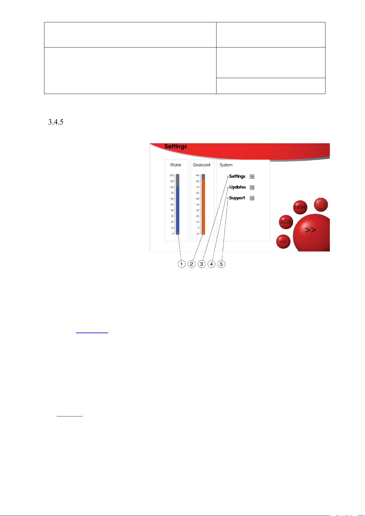
Settings Screen
1) Water level display
2) Desiccant condition display
3) Settings menu
4) Updates menu
5) Support menu
The water level and desiccant level indicators show approximate levels only. The desiccant
level indicator is updated only when the HygroGen2 is drying at more than 15% power and
will take a few minutes to update. This is to ensure the desiccant sensor is reading the correct
value. See section 8.2 for more details.
The drop-down menus (items 3, 4 & 5) allow navigation to screens that are detailed later in this
document.
i. Activation of Enhanced Features
Enhanced Features can be activated via the “Upgrade Features” option on the “Updates” dropdown menu in Configuration Mode, or via the Settings screen in Standard Operation Mode.
See section 4 for more details about Enhanced Features.
© 2020; Rotronic AG E-M-HG2-S-XL-V3.4
Page 37
E-M-HG2-S-XL-V3.4
Rotronic AG
Bassersdorf, Switzerland
Instruction Manual
Instruction Manual for Software
Version 3.4
Document Type
Document title
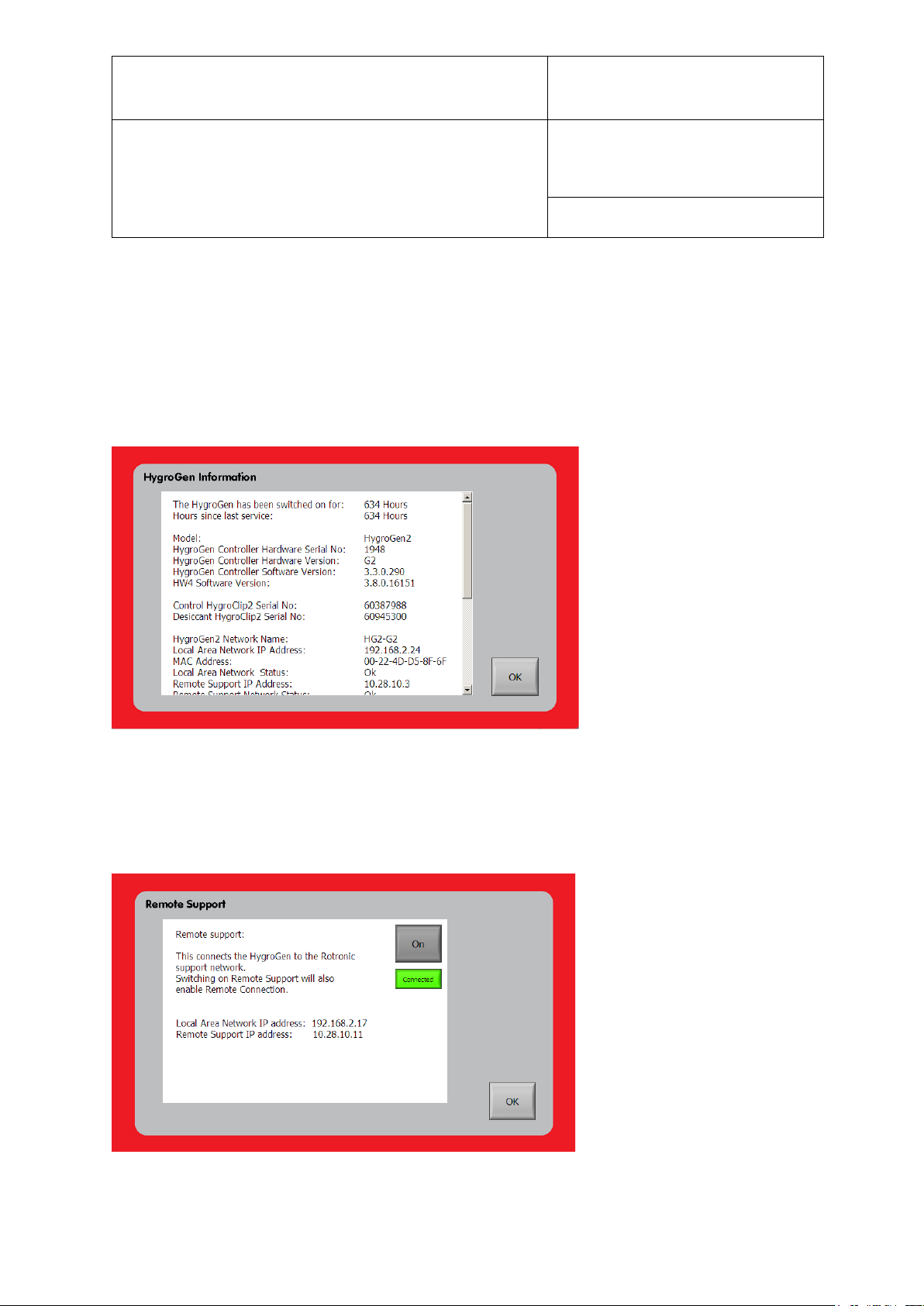
Figure 17: HygroGen Information
Document code Unit
HygroGen2: Humidity and Temperature Generator
with AutoCal, Chilled Mirror External Reference, Remote
Screen Share, RemoteAPI and Range Extension options.
Page 36 of 101
ii. HygroGen Information
General instrument information including serial numbers, software versions, network
parameters and enabled features can be found on the HygroGen Information screen. This can
be found on the “Support” dropdown menu On the Configuration screen and the Settings
screen (when in normal use).
iii. Remote Support
© 2020; Rotronic AG E-M-HG2-S-XL-V3.4
Page 38

E-M-HG2-S-XL-V3.4
Rotronic AG
Bassersdorf, Switzerland
Instruction Manual
Instruction Manual for Software
Version 3.4
Document Type
Document title
Document code Unit
HygroGen2: Humidity and Temperature Generator
with AutoCal, Chilled Mirror External Reference, Remote
Screen Share, RemoteAPI and Range Extension options.
Page 37 of 101
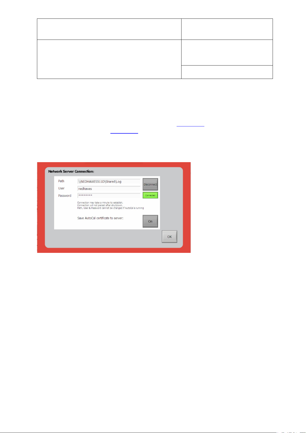
Figure 18: Remote Support
Your HygroGen2 can be configured so that ROTRONIC support engineers can connect to your
HygroGen2 and to its support network so that they can remotely control your HygroGen2.
The feature requires the HygroGen2 to be connected to a network, and the instrument to be
appropriately configured for network access. See section Section 3.3.1 Network Settings.
To enable the Remote Support functionality, select the “Remote Support” option from the
“Support” drop-down menu on the Settings screen. The “On”/” Off” button enables/disables
the functionality.
Please note, the Remote Support functionality establishes a Virtual Private Network (VPN)
tunnel back to the Rotronic support network. Outgoing VPN connections must be permitted on
your local network for it to work. Some IT administrators may block this functionality.
If the HygroGen2 can establish a connection back to the support network, it will show
“Connected” in green. Please advise your Rotronic support representative of the Remote
Support IP address so that they can connect to your instrument.
Please note: the Remote Support connectivity will remain active until it is disabled, even if
the HygroGen2 is rebooted.
© 2020; Rotronic AG E-M-HG2-S-XL-V3.4
Page 39
E-M-HG2-S-XL-V3.4
Rotronic AG
Bassersdorf, Switzerland
Instruction Manual
Instruction Manual for Software
Version 3.4
Document Type
Document title
Document code Unit
HygroGen2: Humidity and Temperature Generator
with AutoCal, Chilled Mirror External Reference, Remote
Screen Share, RemoteAPI and Range Extension options.
Page 38 of 101
iv. Connections to Network File Servers
With the HygroGen2 connected to a LAN, the instrument has the ability to connect to a
network file server for the storage of HW4 log files (see Section 6.4) and [Enhanced Feature]
AutoCal calibration data (see Section 4.1). This function requires the SMB1 protocol to be enabled
on the network file server.
Figure 19: Connection to Remote File Server
To connect to a network file server, select the “File Save Location” option from the “Settings”
drop-down menu on the Settings screen. Enter the network file server path in the format
“\\<server ip or network address>\folder” and enter the username and password for the file
share.
If a successful connection is made, a green ‘Connected’ indicator appears. To establish a
connection with a different file server, press the green ‘Disconnect’ button and put in the new
server details.
Please note, for security reasons the network file server path and user credentials have to be reentered every time the HygroGen2 is restarted.
© 2020; Rotronic AG E-M-HG2-S-XL-V3.4
Page 40

E-M-HG2-S-XL-V3.4
Rotronic AG
Bassersdorf, Switzerland
Instruction Manual
Instruction Manual for Software
Version 3.4
Document Type
Document title
Document code Unit
HygroGen2: Humidity and Temperature Generator
with AutoCal, Chilled Mirror External Reference, Remote
Screen Share, RemoteAPI and Range Extension options.
Page 39 of 101
4 HygroGen2 Enhanced Features
There are up to six Enhanced Features currently available for the HygroGen2. There are
various combination bundle packs available at discount rates; please see HygroGen2 datasheet
for details or contact your ROTRONIC dealer.
Low Temperature and Humidity Range Extensions extend the limits of points that can be
set on the instrument, creating chamber conditions down to -5 °C and from 2 %rh up to
99 %rh. Combined range settings (for example setpoints of -5°C and 2%rh) can be set, but the
HygroGen2 may not achieve the conditions. Typically, the minimum achievable Dew Point is 35°C, but individual HygroGen2 performance will be dependent on chamber loading and
desiccant, ambient & instrument condition.
AutoCal allows you to pre-program a series of set-points and times and record the instrument’s
progression through them in a PDF Calibration Certificate which is written to an external USB
disk drive. Any values recorded on ROTRONIC HC2-X, HC2A-X or HCD-X probes attached
to the HygroGen2 via USB adaptors are recorded in the certificate. Probes can be set to
automatically adjust to match the HygroGen2 reference probe at predetermined values.
Remote Screen Share (Formerly Remote Control) gives the ability to remotely control the
HygroGen2 over a network using the open source VNC protocol.
RemoteAPI gives the ability to remotely control and interrogate the HygroGen2 using a series
of text-based commands over a network; users can write their own software to log and control
the HygroGen2.
External Reference extends the functionality of AutoCal and/or RemoteAPI, by integrating
MBW/RHS or Michell chilled mirror hygrometers (supplied separately) as the external
reference.
Please see the following sections for detailed descriptions of the operation of each of the
Enhanced Features.
Feature Activation
HygroGen2 features are enabled by the application of an activation code. Please purchase an
activation code for the desired features from your ROTRONIC dealer. You will need to
supply your HygroGen2 serial number (see rear of instrument) when ordering the code.
Alternatively, go to the Settings screen and select the appropriate feature from the Settings
drop-down menu and supply the code as given in the format “XXXXXX.YY-Z-ABC”.
© 2020; Rotronic AG E-M-HG2-S-XL-V3.4
Page 41

E-M-HG2-S-XL-V3.4
Rotronic AG
Bassersdorf, Switzerland
Instruction Manual
Instruction Manual for Software
Version 3.4
Document Type
Document title
Document code Unit
HygroGen2: Humidity and Temperature Generator
with AutoCal, Chilled Mirror External Reference, Remote
Screen Share, RemoteAPI and Range Extension options.
Page 40 of 101
To activate Enhanced Features on your HygroGen2, you will need a USB keyboard plugged
into the HygroGen2 to type in the supplied code, which will be a 16-digit string of numbers
and letters in CAPITALS. The code will activate all the features you have purchased. If you
have previously purchased one or more features and you want to add another, a new code will
be supplied enabling both/all features.
To activate the upgrade features, go to the Settings screen, select the “Updates” drop-down
menu and choose “Upgrade Features”. Type in the supplied code, ensuring there are no extra
characters or spaces at the end of the string. The green lights will light up displaying the
purchased Enhanced Features, which will be available immediately.
© 2020; Rotronic AG E-M-HG2-S-XL-V3.4
Page 42

E-M-HG2-S-XL-V3.4
Rotronic AG
Bassersdorf, Switzerland
Instruction Manual
Instruction Manual for Software
Version 3.4
Document Type
Document title
Document code Unit
HygroGen2: Humidity and Temperature Generator
with AutoCal, Chilled Mirror External Reference, Remote
Screen Share, RemoteAPI and Range Extension options.
Page 41 of 101
4.1 AutoCal
Top Level Menu and Programmer Function
With AutoCal activated, the AutoCal screen (see Figure 13) is displayed instead of the
Programmer Function Screen. The standard Programmer functionality, as described in section
3.4.3 is still available but is accessed via the drop-down menu in the top left hand corner of the
screen.
AutoCal Reference
The standard version of AutoCal uses the internal control HC2-S as its reference. AutoCal+ is
an extension to AutoCal which enables the selection of an external Michell or MBW/RHS dew
point hygrometer as an external reference. For more details on using AutoCal+, see section 4.2.
For a more in-depth discussion of references and calibration traceability, please see Appendices
A1: Calibration Reference Options and A2: Temperature Control.
AutoCal Compatible Probes
Autocal supports the calibration and adjustment of HC2-X, HC2A-X and HCD-X probes.
Probes must be connected to the HygroGen2 front USB ports. A maximum of 6 probes can be
connected at a time.
HCD-X probes MUST be updated to firmware version 1.5 or above.
© 2020; Rotronic AG E-M-HG2-S-XL-V3.4
Page 43
E-M-HG2-S-XL-V3.4
Rotronic AG
Bassersdorf, Switzerland
Instruction Manual
Instruction Manual for Software
Version 3.4
Document Type
Document title
Document code Unit
HygroGen2: Humidity and Temperature Generator
with AutoCal, Chilled Mirror External Reference, Remote
Screen Share, RemoteAPI and Range Extension options.
Page 42 of 101
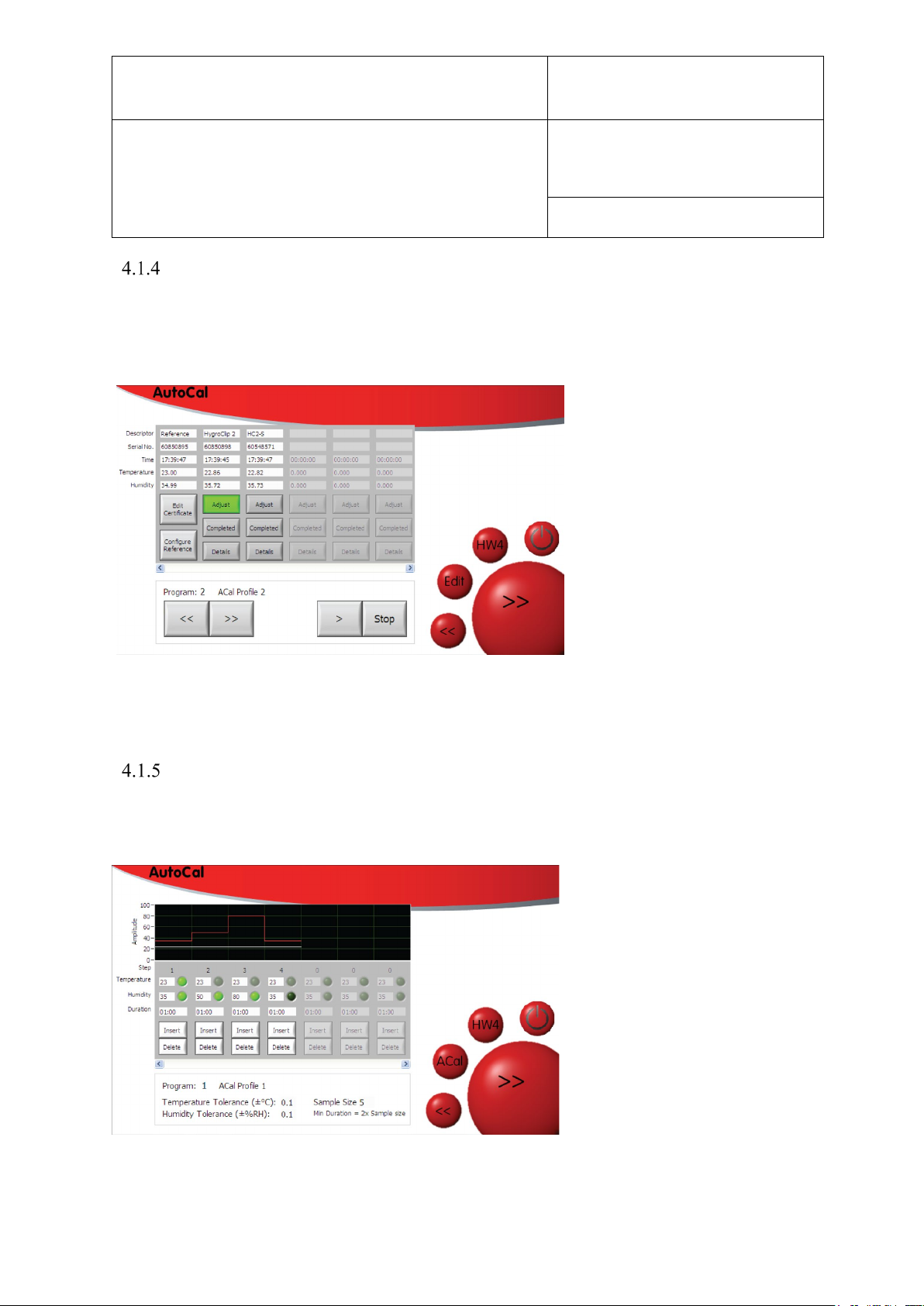
AutoCal Screen
As ROTRONIC probes are added via the USB ports, the individual probe slots are populated
within the AutoCal Screen. During an AutoCal calibration run, probes can be adjusted, or not,
as desired, for each probe. Select individual probes by selecting the “Adjust” button.
Figure 20: Adding probes and selecting to adjust
AutoCal Program Edit
Pressing the Edit button calls up the AutoCal Program Edit screen.
Figure 21: AutoCal Program Edit Screen
© 2020; Rotronic AG E-M-HG2-S-XL-V3.4
Page 44

E-M-HG2-S-XL-V3.4
Rotronic AG
Bassersdorf, Switzerland
Instruction Manual
Instruction Manual for Software
Version 3.4
Document Type
Document title
Document code Unit
HygroGen2: Humidity and Temperature Generator
with AutoCal, Chilled Mirror External Reference, Remote
Screen Share, RemoteAPI and Range Extension options.
Page 43 of 101
Set-points are programmed in an identical way to the standard Programmer. However, the
green buttons take on a different function; they are now used to determine the adjustment
points. Probes that are selected for adjustment within the AutoCal Screen will be adjusted at
points that are selected here. Only one temperature point can be selected and must be selected
as the first adjustment point. Greyed out buttons refer to options that are not possible, a dark
green button is a point not selected for adjustment and bright green is a point selected for
adjustment.
Points can be set for a minimum duration of 15 minutes; please ensure sufficient time is
allowed for the probe to stabilise. A duration of at least an hour is strongly recommended,
longer for extremes of temperature or RH. The timing of a set-point will begin when the
chamber is within the set tolerance. Take particular care to allow sufficient time to allow for
stabilisation of probes with particular protection filters applied.
It is not possible to select different adjustment points for different probes. If this is desired,
please run a new program at a later time.
Tolerance and Sample Size
As with the Standard Programmer, for each program, temperature and humidity stabilisation
values can be defined. Once the chamber conditions are within this tolerance, the step duration
timing begins. If set to zero, no stabilisation criteria are applied and the timing of the step
duration begins immediately. The number of samples recorded in the AutoCal certificate can
also be defined from 5 to 50; working backwards from the end of each set-point duration,
values for temperature and humidity are recorded on the calibration certificate every 2 minutes
for the number of samples selected. This determines the minimum set-point duration above an
absolute minimum of 15 minutes.
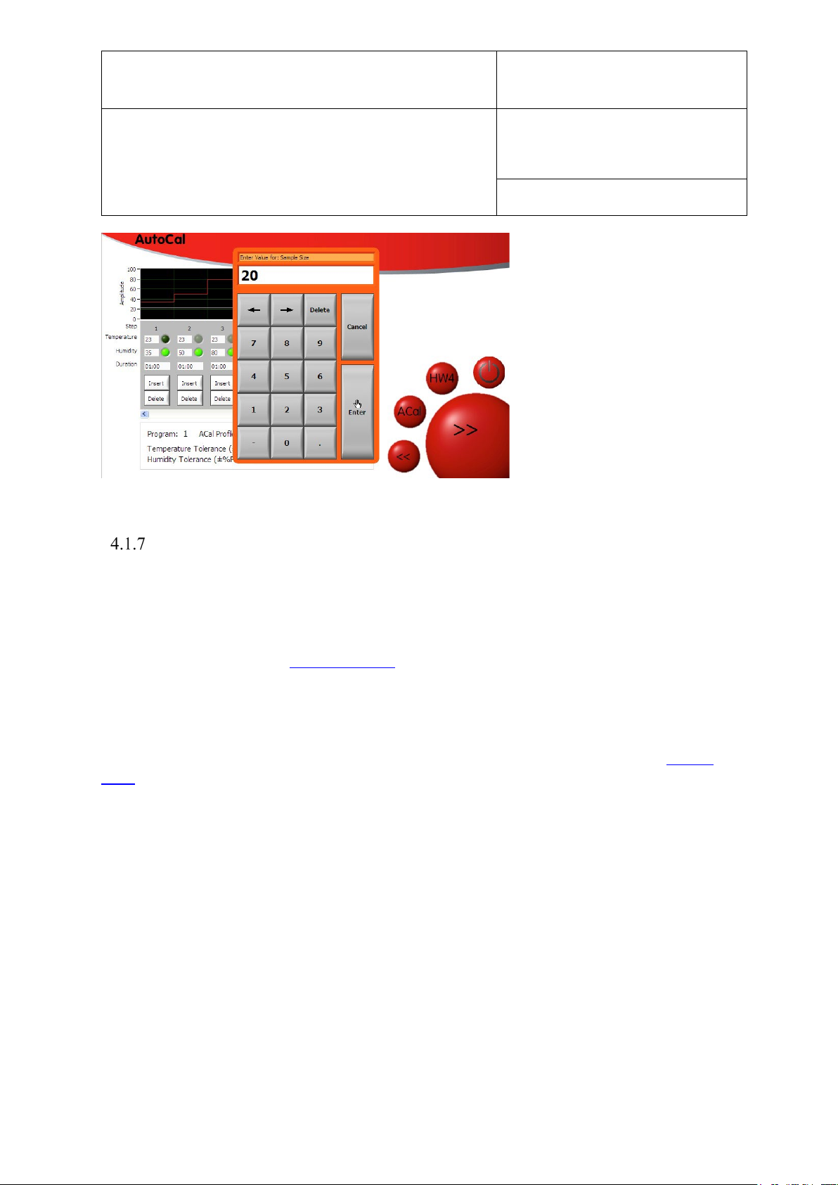
To change these parameters, click the number next to each one. For example, in figure 22, to adjust the
sample size, click the number after the parameter. This will show the number entry window.
© 2020; Rotronic AG E-M-HG2-S-XL-V3.4
Page 45
E-M-HG2-S-XL-V3.4
Rotronic AG
Bassersdorf, Switzerland
Instruction Manual
Instruction Manual for Software
Version 3.4
Document Type
Document title
Document code Unit
HygroGen2: Humidity and Temperature Generator
with AutoCal, Chilled Mirror External Reference, Remote
Screen Share, RemoteAPI and Range Extension options.
Figure 22: Number Entry Window
Page 44 of 101
AutoCal Operation and Best Practices
Once the program and adjustment points are determined, programs are started by pressing the
“Play” (>) button. After a successful run (provided AutoCal has successfully communicated
with the probe under test for every selected sample point at every set-point), AutoCal saves a
time-stamped PDF calibration certificate to a USB drive plugged into the HygroGen2, or an
external network drive (see Section 3.4.5.iv). The same information is stored in a
corresponding .csv file. If, for any reason, communication with the probe under test is
interrupted (by unplugging the probe, for example), only the .csv file will be saved, with the
associated data actually recorded. Included in each file is the program name, set- and
adjustment-points, probe serial numbers and relevant calibration reference information. It is
possible to upload a custom logo and add other user and reference information (see section
4.1.7). A separate PDF is generated for each probe. NB: AutoCal will not run unless a USB
drive is detected by the HygroGen2 or a network file share has been configured.
Before selecting a probe for adjustment, it is recommended to perform an initial assessment
calibration run without adjustment selected. At the end of the run, examine the saved PDF
calibration certificate and determine whether you want to re-run the program with adjustment
selected.
At the first adjustment-point to be applied, AutoCal will delete any previously saved
calibration points stored on the probe. This is action recorded on the certificate. It will then
apply the values of the reference probe as a corrected value. This value is determined at the
instant the correction is saved and is not an average of the previously recorded points as shown
in the calibration certificate; these are shown in the certificate to give the user an estimate of
stability.
© 2020; Rotronic AG E-M-HG2-S-XL-V3.4
Page 46

E-M-HG2-S-XL-V3.4
Rotronic AG
Bassersdorf, Switzerland
Instruction Manual
Instruction Manual for Software
Version 3.4
Document Type
Document title
Document code Unit
HygroGen2: Humidity and Temperature Generator
with AutoCal, Chilled Mirror External Reference, Remote
Screen Share, RemoteAPI and Range Extension options.
Page 45 of 101
Please note, for probes with adjustment selected, AutoCal will always attempt to make an
adjustment. If the correction is smaller than the resolution of the probe itself, the adjustment
may not be applied.
If, at the end of the run, the probe has acknowledged all instructions it has been sent, the
“Completed“ button will turn green on the AutoCal screen and the PDF is saved to the USB
drive. Details of the probe’s progress throughout the run can be viewed via the “Details”
button.
Please note, the performance of a HygroClip probe within its stated specification is based on
temperature adjustment being made at 23 °C. AutoCal does permit the adjustment to be made
at other temperatures. However, this is only recommended when the operational environment
of the probe being adjusted is only ever at another specific temperature, e.g. a stability cabinet
at
40 °C. Adjustments made at temperatures other than 23 °C risk comprising the probe’s ability
to meet its specification within the range of optimal performance: 18 to 28 °C.
Please note that HW4 cannot be used at the same time as AutoCal.
© 2020; Rotronic AG E-M-HG2-S-XL-V3.4
Page 47
E-M-HG2-S-XL-V3.4
Rotronic AG
Bassersdorf, Switzerland
Instruction Manual
Instruction Manual for Software
Version 3.4
Document Type
Document title
Document code Unit
HygroGen2: Humidity and Temperature Generator
with AutoCal, Chilled Mirror External Reference, Remote
Screen Share, RemoteAPI and Range Extension options.
Customising the PDF Calibration Certificate
Page 46 of 101
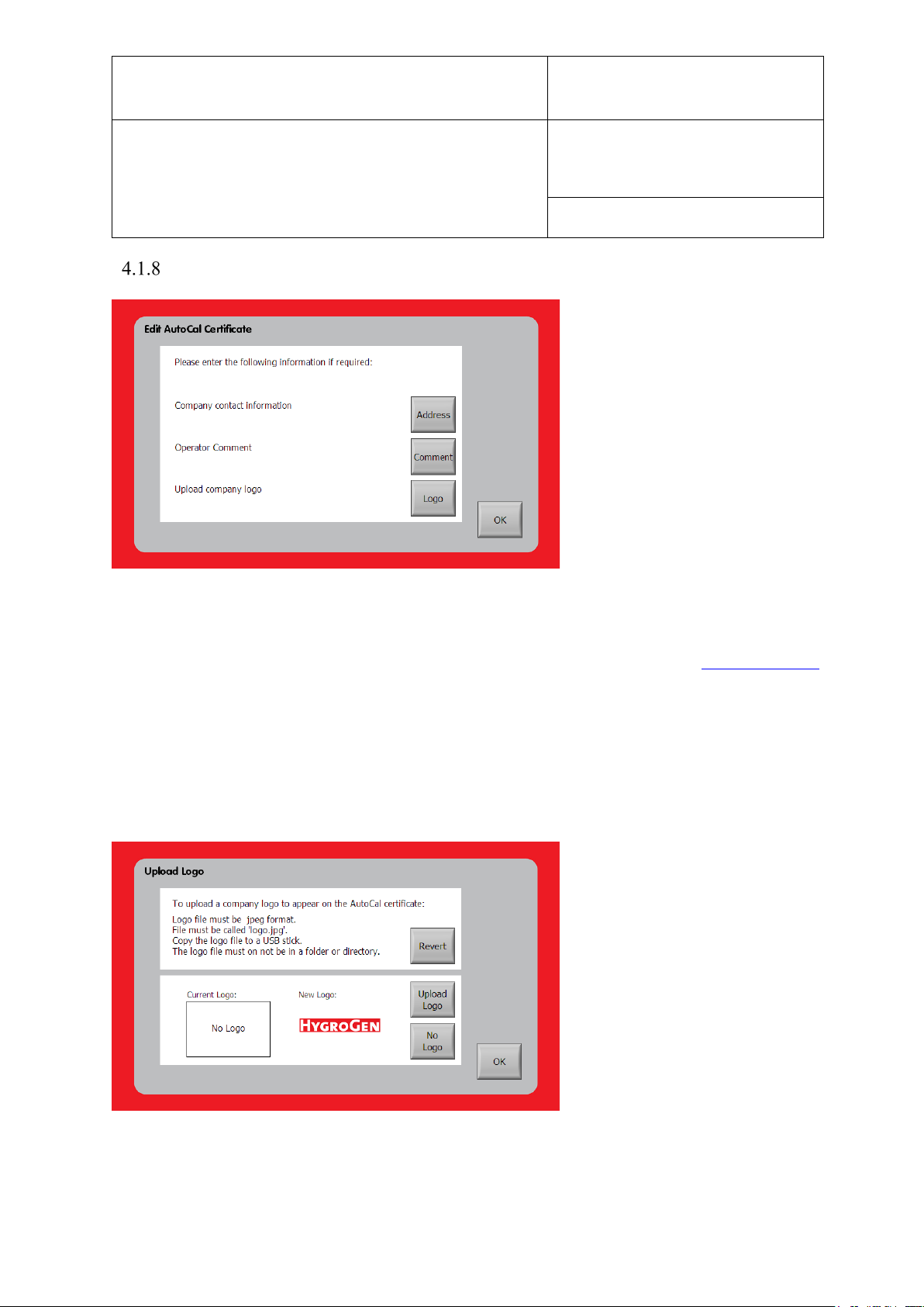
Figure 23: Edit AutoCal Certificate
The PDF certificate can be customised by selecting “Edit Certificate” from the AutoCal Screen
(Figure 20) or selecting “AutoCal” from the Settings menu on the Settings screen. It is possible
to enter user and company information and to upload a custom logo.
To upload a logo, save it as a file “logo.jpg” to the root directory of a USB stick. Insert the
USB into the HygroGen2. The HygroGen2 will detect the file and display your image. Select
“Upload Logo”. The logo will be uploaded to the unit and will appear automatically sized and
positioned on the PDF certificate below the “HygroGen” logo.
Figure 24: Upload Logo
© 2020; Rotronic AG E-M-HG2-S-XL-V3.4
Page 48
E-M-HG2-S-XL-V3.4
Rotronic AG
Bassersdorf, Switzerland
Instruction Manual
Instruction Manual for Software
Version 3.4
Document Type
Document title
Document code Unit
HygroGen2: Humidity and Temperature Generator
with AutoCal, Chilled Mirror External Reference, Remote
Screen Share, RemoteAPI and Range Extension options.
Page 47 of 101
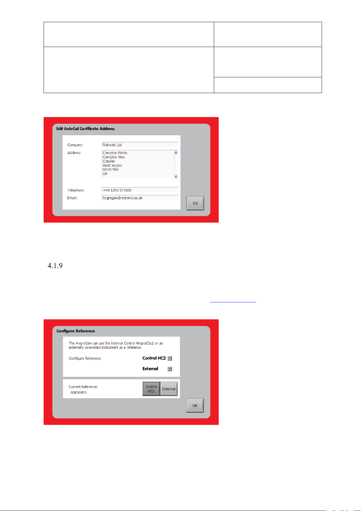
Enter company information in the Edit AutoCal Certificate Contact Information screen.
Figure 25: Edit AutoCal Certificate Contact Information
Reference Information
The HygroGen2 AutoCal function can use either the internal control HygroClip2 or an
externally connected Chilled Mirror Hygrometer as a reference. Information about the devices
can be entered by pressing “Configure Reference” in the AutoCal Screen (Figure 20) or
selecting “Reference” from the “Settings” drop-down menu on the Settings screen,
Figure 26: Edit AutoCal Reference
© 2020; Rotronic AG E-M-HG2-S-XL-V3.4
Page 49
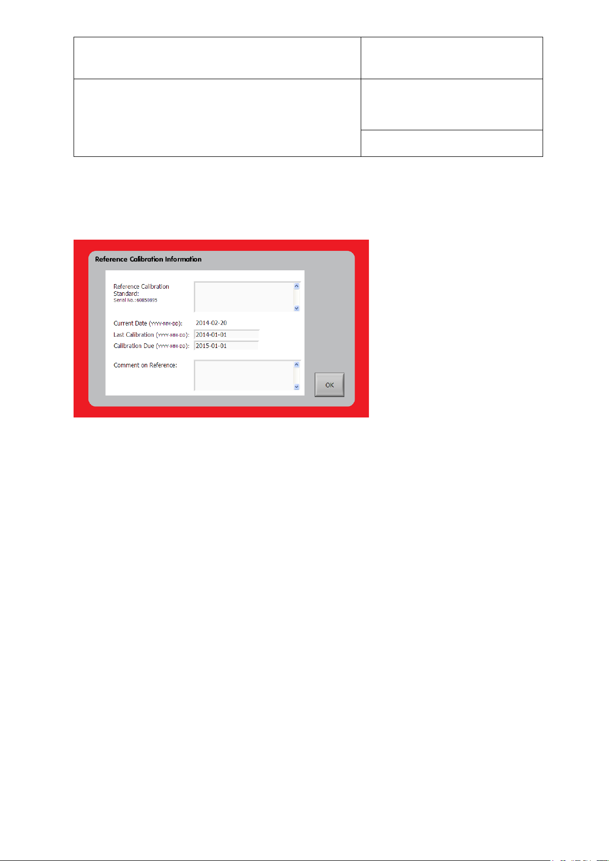
E-M-HG2-S-XL-V3.4
Rotronic AG
Bassersdorf, Switzerland
Instruction Manual
Instruction Manual for Software
Version 3.4
Document Type
Document title
Document code Unit
HygroGen2: Humidity and Temperature Generator
with AutoCal, Chilled Mirror External Reference, Remote
Screen Share, RemoteAPI and Range Extension options.
Page 48 of 101
and selecting the “Calibration Info” from the “Control HC2-S” drop-down menu (for the
HygroClip2) and ‘External’ drop-down menu (for the external reference instrument -if
connected).
Figure 27: Edit AutoCal Reference Information
Reference calibration information can be entered here, including the last and next-due
calibration dates and any comments.
When an AutoCal run is started, the user is warned if the reference calibration is out of date
and prompted to update the reference information if the reference probe have been changed. If
a reference that has previously been used and has reference information stored on the
HygroGen2 is restored to the instrument, the information will automatically be reapplied.
© 2020; Rotronic AG E-M-HG2-S-XL-V3.4
Page 50
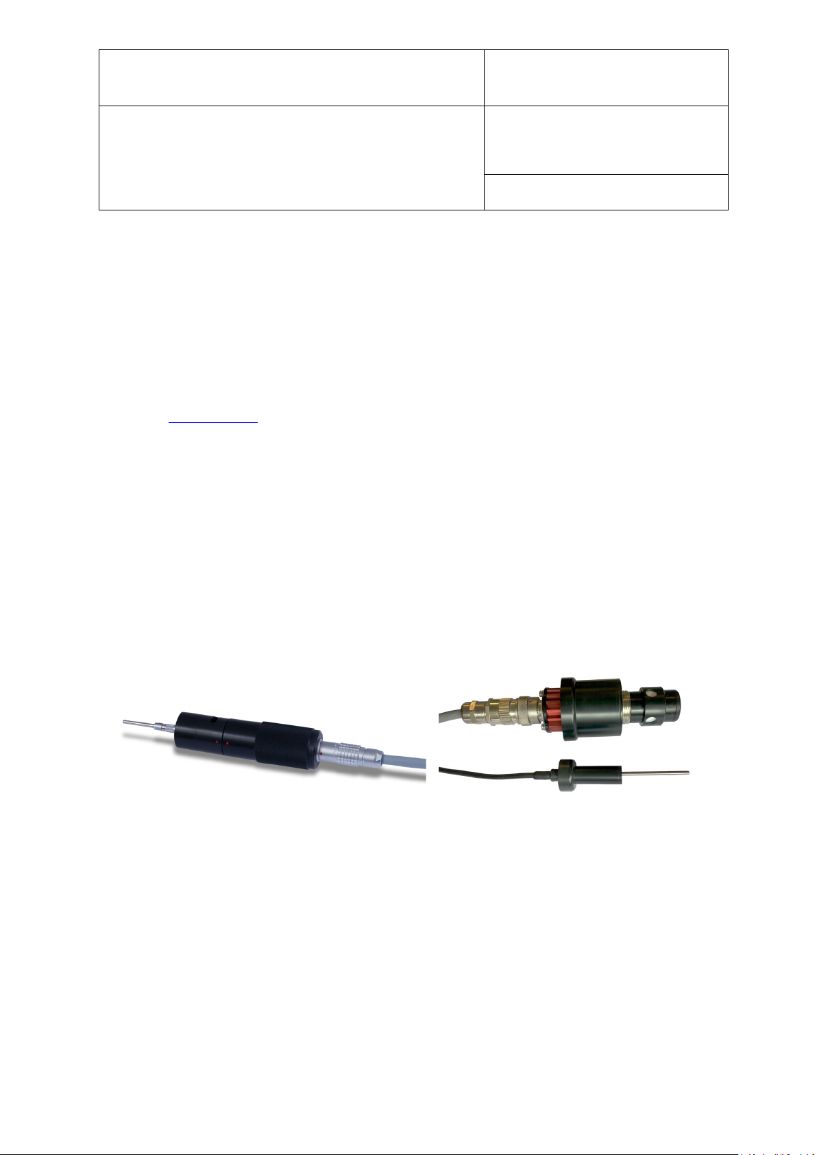
E-M-HG2-S-XL-V3.4
Rotronic AG
Bassersdorf, Switzerland
Instruction Manual
Instruction Manual for Software
Version 3.4
Document Type
Document title
Document code Unit
HygroGen2: Humidity and Temperature Generator
with AutoCal, Chilled Mirror External Reference, Remote
Screen Share, RemoteAPI and Range Extension options.
Page 49 of 101
4.2 Chilled Mirror Reference Systems
To reduce further measurement uncertainties that can be achieved with the HygroGen2,
ROTRONIC has worked with MBW and Michell Instruments to integrate their products into
the HygroGen2. Particularly well suited are the MBW473 and Michell S8000 Dew Point
Mirrors. Other models can be connected via the heated Swagelok sample ports on the rear of
the instrument.
For an in-depth discussion on measurement uncertainty and the choice of calibration reference,
please see Appendix A1.
In order to calculate relative humidity (RH) from a dew point (chilled mirror) hygrometer, you
also need to make continuous temperature measurements of the chamber. The 473 and S8000
instruments have the ability to record the chamber temperature. The 473 with RP2 head
combination has the temperature probe on the end of the head, which can be optionally
connected via a cable to position it elsewhere in the chamber. The S8000 temperature probe is
connected independently of the remote head via a separate door port. Note the S8000 head
should be used with the Remote Guard air filter (part number: S8K-REM-TSG) as shown.
Figure 28: MBW RP2 & Michell S8000 (including door adapters) remote head
Alternatively the MBW SH2 remote head may be placed fully inside the HG2-XL chamber.
© 2020; Rotronic AG E-M-HG2-S-XL-V3.4
Page 51
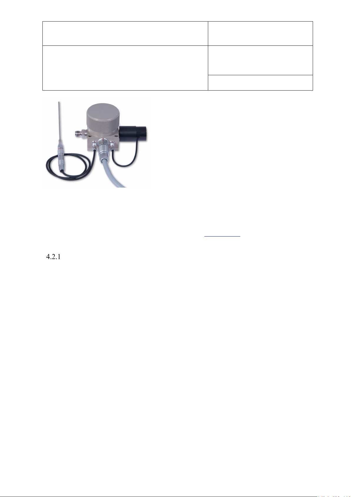
E-M-HG2-S-XL-V3.4
Rotronic AG
Bassersdorf, Switzerland
Instruction Manual
Instruction Manual for Software
Version 3.4
Document Type
Document title
Document code Unit
HygroGen2: Humidity and Temperature Generator
with AutoCal, Chilled Mirror External Reference, Remote
Screen Share, RemoteAPI and Range Extension options.
Page 50 of 101
Figure 29: MBW SH2 remote head
Relative humidity is calculated on MBW instruments using the Sonntag/Hardy equation. The
same algorithm is implemented into the HygroGen2 (see section 4.2.2).
Connecting and Configuring an External Reference
Please also refer to the instruction manual appropriate to your external reference instrument.
Michell:
The Michell S8000 utilises an inbuilt RS232-USB converter and can be directly connected via
a USB A>B cable to the HygroGen2.
MBW:
Connection to an MBW Chilled Mirror requires a USB – RS232 adapter and a male-female
RS-232 extension cable. Please consult with your Rotronic Supplier to determine the best
adapter to use. Earlier units can utilise an Aten UC-232A USB-RS232 later units will work
with most Prolific based adapters.
Please note that some cheaper adapters may not be genuine parts and may not be well
supported. This may cause communication instability between the instruments.
Make sure the reference hygrometer is plugged in, turned on and is connected to the
HygroGen2. Only one external reference device should be connected to the HygroGen2 at
once.
© 2020; Rotronic AG E-M-HG2-S-XL-V3.4
Page 52
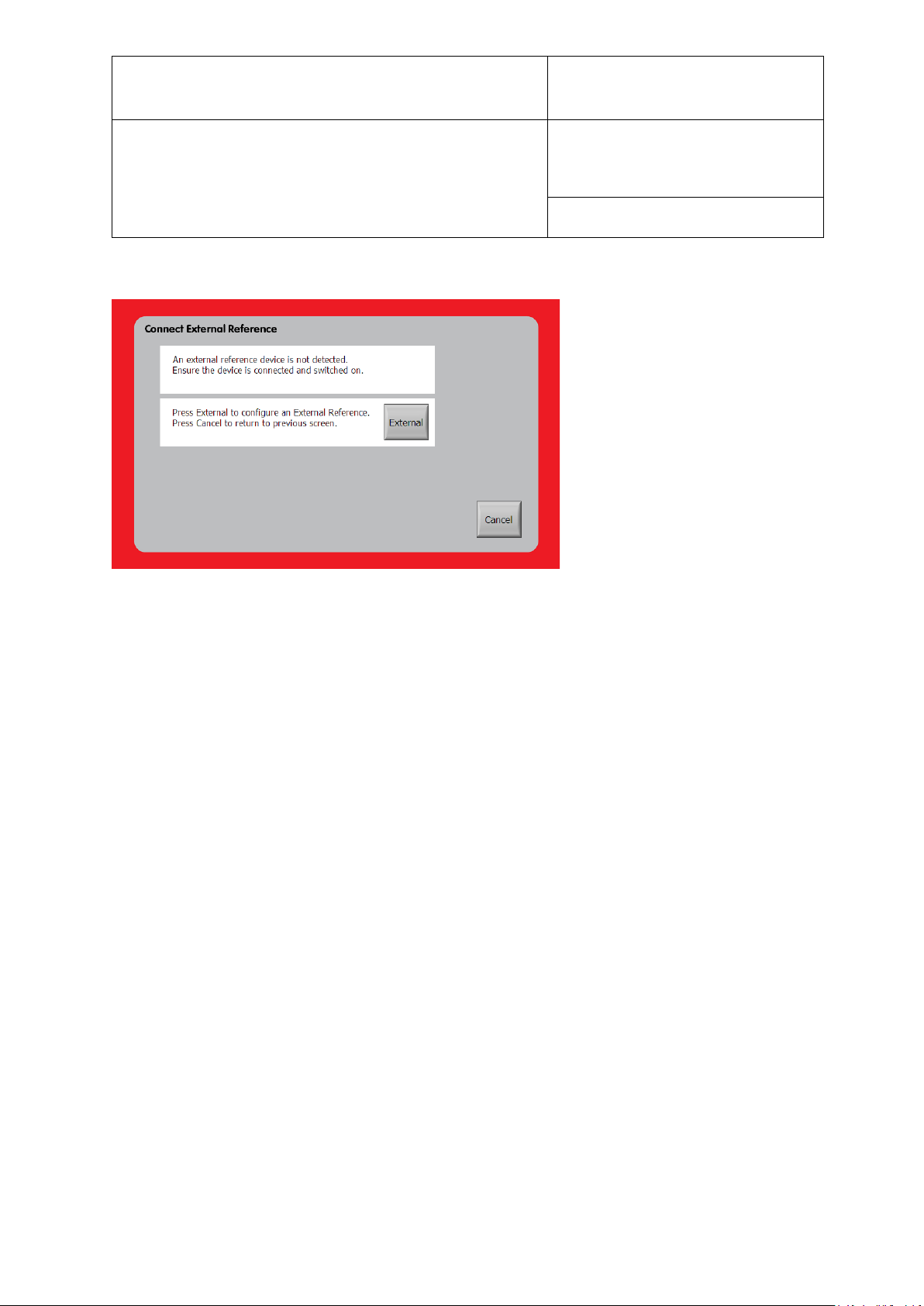
E-M-HG2-S-XL-V3.4
Rotronic AG
Bassersdorf, Switzerland
Instruction Manual
Instruction Manual for Software
Version 3.4
Document Type
Document title
Document code Unit
HygroGen2: Humidity and Temperature Generator
with AutoCal, Chilled Mirror External Reference, Remote
Screen Share, RemoteAPI and Range Extension options.
Page 51 of 101
To configure an external reference, select “Connection” from the “External” drop-down menu.
Figure 30: Connect External Reference
Once this is done, click “Scan” and your instrument should be detected.
MBW: Click “Select”, and then click OK.
Michell: Manually enter the S8000 serial number from the label on the back of the instrument,
click the “OK” button next to the Serial number. This appends the serial number to the
“Connected instrument” text and becomes the identifier for this instrument. Click the “Select”
button to use this instrument as the external reference, and then click the bottom right OK
button.
The S8000 does not store its serial number electronically so it must be added manually if the
serial number is to appear on the generated AutoCal certificate. The operator is asked to
confirm the S8000 serial number each time the S8000 or HygroGen2 is restarted to ensure the
reference instrument has not been changed. It is the operator’s responsibility to ensure that the
serial number of the S8000 matches the serial number entered on the “External Reference
Connection” screen.
© 2020; Rotronic AG E-M-HG2-S-XL-V3.4
Page 53
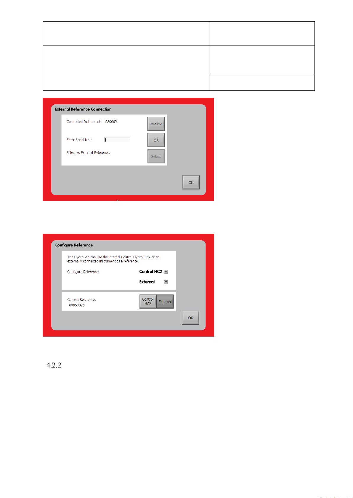
E-M-HG2-S-XL-V3.4
Rotronic AG
Bassersdorf, Switzerland
Instruction Manual
Instruction Manual for Software
Version 3.4
Document Type
Document title
Document code Unit
HygroGen2: Humidity and Temperature Generator
with AutoCal, Chilled Mirror External Reference, Remote
Screen Share, RemoteAPI and Range Extension options.
Page 52 of 101
Figure 31: Scanning for Connected Devices
On the “Configure Reference” screen, select “External” as the current reference.
Figure 32: Select External Reference
Measurement Type (MBW only)
MBW gives you the choice between using the RH value as determined by the external
reference directly or by using the Dew/Frost Point from the external reference. If Dew/Frost
Point is selected the HygroGen2 will calculate the RH.
© 2020; Rotronic AG E-M-HG2-S-XL-V3.4
Page 54
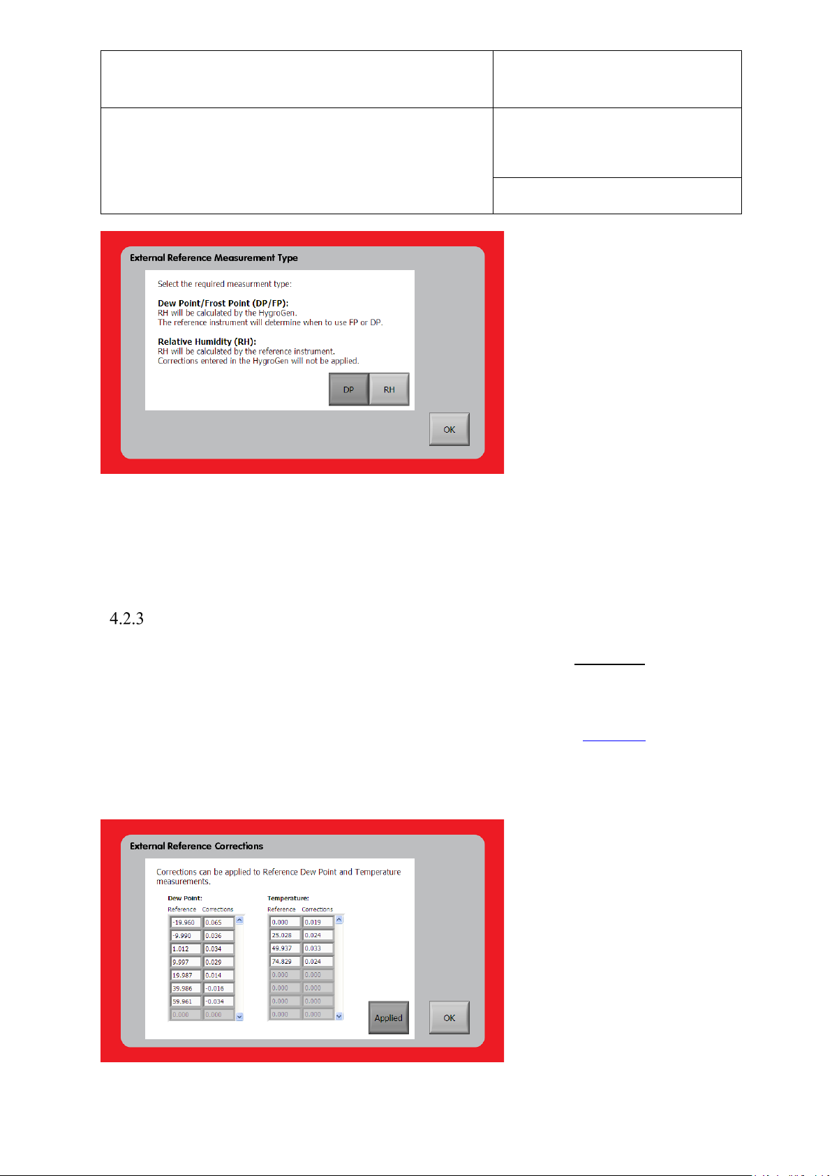
E-M-HG2-S-XL-V3.4
Rotronic AG
Bassersdorf, Switzerland
Instruction Manual
Instruction Manual for Software
Version 3.4
Document Type
Document title
Document code Unit
HygroGen2: Humidity and Temperature Generator
with AutoCal, Chilled Mirror External Reference, Remote
Screen Share, RemoteAPI and Range Extension options.
Page 53 of 101
Figure 33: Measurement Type (MBW only)
Select the desired Measurement type: Dew Point or Relative Humidity. If selecting Dew Point,
please proceed to the Corrections section to enter calibration certificate data. The choice is
recorded on the certificate.
Corrections (MBW only)
When getting your dew point hygrometer calibrated, please request a dew point calibration
with corrections from your calibration supplier and a table of corrections for applied set-points
for your external temperature probe. Note that some calibration labs may supply points below
zero in terms of frost point. These need to be converted into dew point values. A useful tool to
do this is the Psychrometric Conversion Utility that’s part of HW4. See Section 6. Enter the
correction values from the instrument’s calibration certificate via the two tables found via the
“Corrections” option in the “External” drop-down menu and press the toggle button so that it
displays “Applied”.
© 2020; Rotronic AG E-M-HG2-S-XL-V3.4
Page 55

E-M-HG2-S-XL-V3.4
Rotronic AG
Bassersdorf, Switzerland
Instruction Manual
Instruction Manual for Software
Version 3.4
Document Type
Document title
Document code Unit
HygroGen2: Humidity and Temperature Generator
with AutoCal, Chilled Mirror External Reference, Remote
Screen Share, RemoteAPI and Range Extension options.
Page 54 of 101
Figure 34: External Reference Corrections
If the corrections are applied the Dew Point and Temperature values used by the HygroGen2
are the corrected values. If the uncorrected valuers are required, toggle the “Applied” button
off and the HygroGen 2 will used the raw values read from the external reference.
© 2020; Rotronic AG E-M-HG2-S-XL-V3.4
Page 56
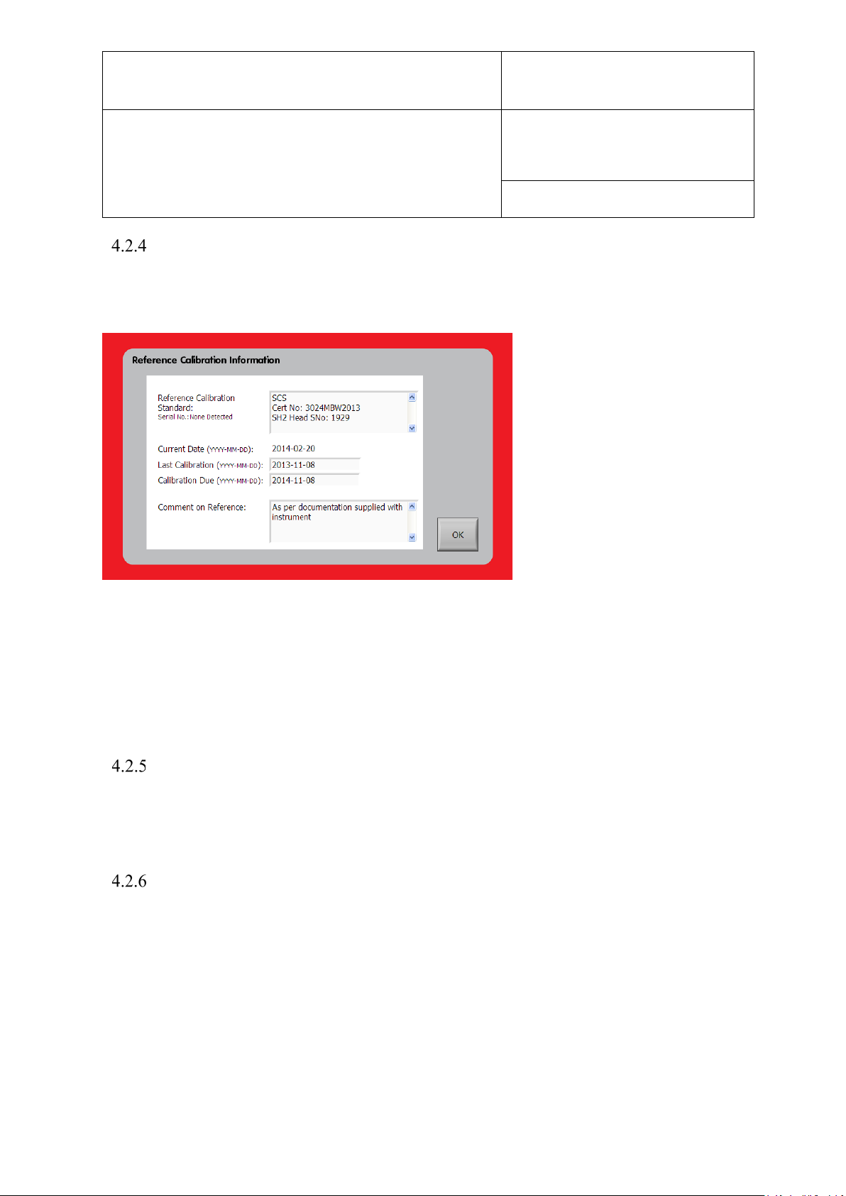
E-M-HG2-S-XL-V3.4
Rotronic AG
Bassersdorf, Switzerland
Instruction Manual
Instruction Manual for Software
Version 3.4
Document Type
Document title
Document code Unit
HygroGen2: Humidity and Temperature Generator
with AutoCal, Chilled Mirror External Reference, Remote
Screen Share, RemoteAPI and Range Extension options.
Page 55 of 101
Calibration Info (MBW & S8000)
Information about the calibration of your external reference can be entered via the “Calibration
Info” option in the “External” drop-down menu.
Figure 35: Reference Calibration Information
Please note that if a different reference is used, the HygroGen2 will warn you to input new
correction and calibration information for the new reference. Calibration corrections and
information is stored on the HygroGen2 for each reference used and will be reapplied to the
appropriate instrument if a reference is used again.
Advanced (Command Line interface) (MBW only)
The “Advanced” option in the “External” drop-down menu displays a command line interface
to the MBW instrument. For details of available commands, see the MBW instruction manual.
Best Practices and Precautions
Please see the manufacturer’s documentation to learn more about the detailed operation of your
dew point hygrometer. However, a few points to take particular note of:
i. Dew/Frost control
Chilled mirror hygrometers work by precisely controlling the temperature of a mirror surface
until the exact point that a dew (or frost) film forms. This dew (or frost) point is a temperature
independent measurement of the humidity level in a gas at a particular pressure. A chilled
mirror measures humidity only if mirror control is switched on. The HygroGen2 will report if
© 2020; Rotronic AG E-M-HG2-S-XL-V3.4
Page 57

E-M-HG2-S-XL-V3.4
Rotronic AG
Bassersdorf, Switzerland
Instruction Manual
Instruction Manual for Software
Version 3.4
Document Type
Document title
Document code Unit
HygroGen2: Humidity and Temperature Generator
with AutoCal, Chilled Mirror External Reference, Remote
Screen Share, RemoteAPI and Range Extension options.
Page 56 of 101
mirror control is switched off, or if the reading is not stable (as determined by the external
reference, not the HygroGen2).
ii. Mirror Cleaning
To make reliable measurements, it is very important that the mirror surface is clean, otherwise
you will observe instability. Oil films and other contamination can condense onto the mirror
surface, which can be transferred from dirty probes under test. See the manufacturer’s
documentation for further details on mirror cleaning.
iii. Decontamination of HygroGen2 chamber
In certain circumstances the HygroGen2 chamber can itself become contaminated, and what
appears to be a stable generated condition on the HygroGen2, is shown on the external mirror
to slowly drift upwards as the contamination condenses on the mirror. This can be an indication
of outgassing of contamination that may have been absorbed within the internal mechanics of
the HygroGen2 or may be present in new instruments as part of the manufacture process. A
mirror clean (either electronic or physical) that resets the drift to its original baseline will
confirm the presence of contamination.
To mitigate this problem, it is recommended to run the HygroGen2 at 60 °C >50 %rh for two
or more days with the chamber filled with a tray of granular activated carbon (GAC).
Use as much GAC as practical. For the HG2-S use a suitable container that pretty much fills
the chamber and fill that with GAC, for the XL use about three large lunch box style plastic
containers filled with GAC.
Confirm afterwards that a mirror clean does not cause a step change in reading, and this will
indicate the contamination has been removed.
iv. Super Cooled Water: Dew or Frost Films. Force Frost Threshold
With any condensing measurement, care needs to be taken for humidity conditions with a dew
point at or just below freezing, typically in the range -7.0 – 0 °C. Super cooled water may exist
on the mirror rather than frost and the temperature at which dew or frost films form is
fractionally different. MBW instruments have a Force Frost function and the S8000 has a Frost
Assurance (FAST) function both of which engage below a pre-set value to ensure a frost rather
than a dew film. MBW typical Force Frost threshold value might be -5 °C. It is recommended
to use the Force Frost functionality but avoid programming set-points with a dew/frost point
between 0 °C and the threshold. The S8000 FAST function can either be on or off.
NB: there is a convenient psychrometric calculation utility within the built-in HW4 software
(see section 6) to calculate dew points. E.g. at 23 °C, 15 %rh dew point is -5 °C, at 23 °C, 21.5
%rh dew point is -0.15 °C. So at 23 °C, avoid 15-22 %rh as a set point.
© 2020; Rotronic AG E-M-HG2-S-XL-V3.4
Page 58
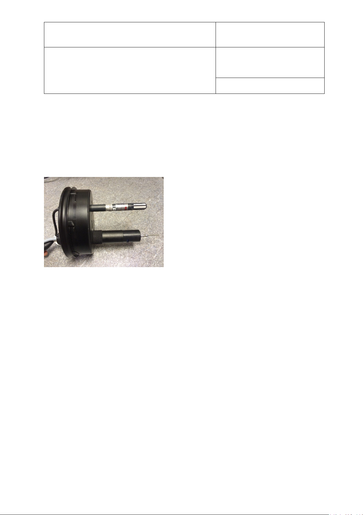
E-M-HG2-S-XL-V3.4
Rotronic AG
Bassersdorf, Switzerland
Instruction Manual
Instruction Manual for Software
Version 3.4
Document Type
Document title
Document code Unit
HygroGen2: Humidity and Temperature Generator
with AutoCal, Chilled Mirror External Reference, Remote
Screen Share, RemoteAPI and Range Extension options.
Page 57 of 101
v. Extremes of Temperature and Humidity
As with any other reference or instrument under test that is inserted through the door, stem
conduction should be considered at the extremes of the HygroGen2’s measurement range.
A recommendation for conditions that are higher than 50 °C, 90 %rh, or 60 °C, 80 %rh is that
the entire RP2 measuring head is mounted on the inside of the door. At these extremes,
condensation will form at cold spots that can be introduced if there is thermal conduction with
the ambient conditions.
Figure 36: Probe mounted on inside door surface
An HG2-B8-9 bung which has a 9-17 mm cable gland can be used to secure the head cable
from the outside of the door and provides further insulation.
© 2020; Rotronic AG E-M-HG2-S-XL-V3.4
Page 59
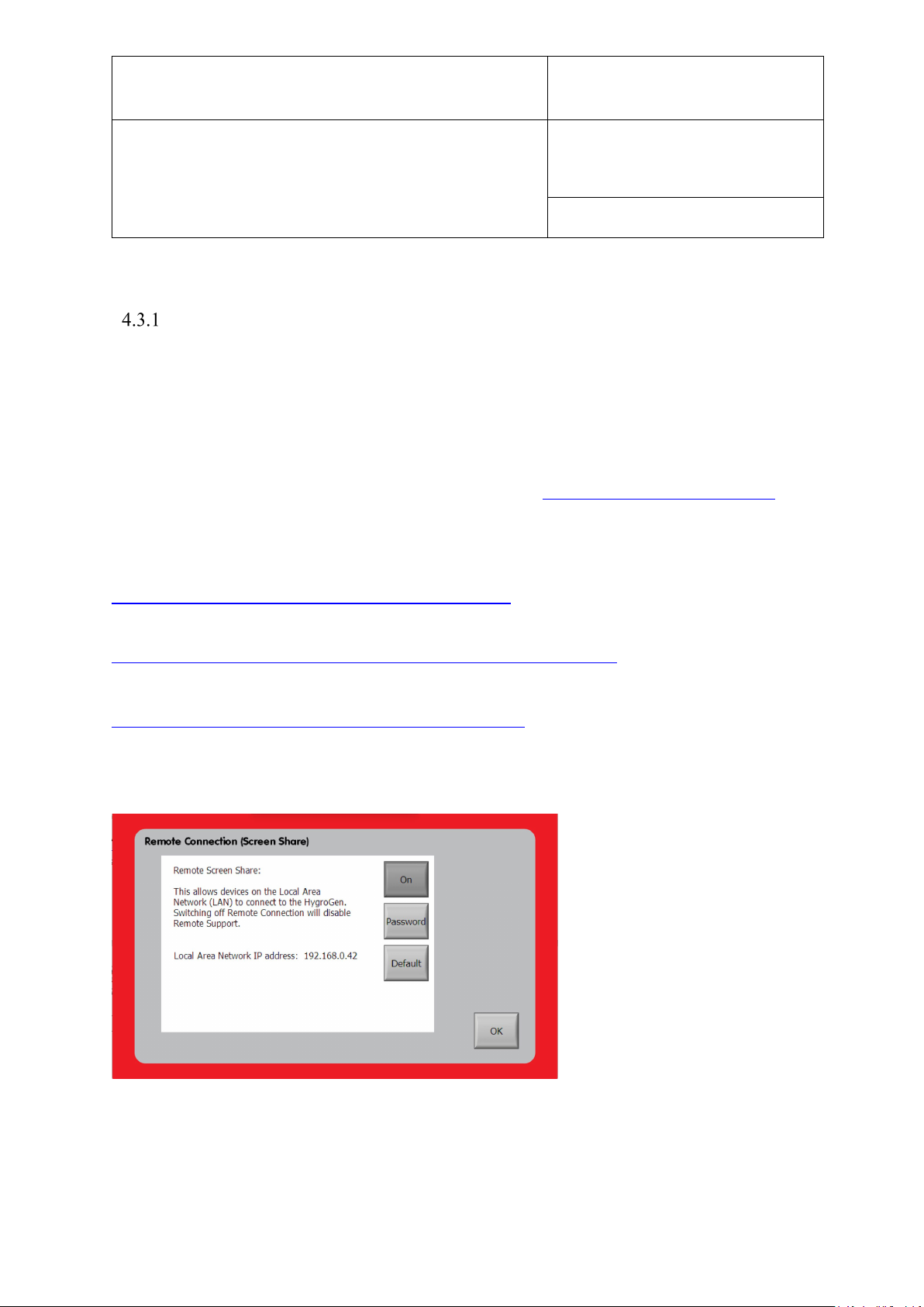
E-M-HG2-S-XL-V3.4
Rotronic AG
Bassersdorf, Switzerland
Instruction Manual
Instruction Manual for Software
Version 3.4
Document Type
Document title
Document code Unit
HygroGen2: Humidity and Temperature Generator
with AutoCal, Chilled Mirror External Reference, Remote
Screen Share, RemoteAPI and Range Extension options.
Page 58 of 101
4.3 Remote Control
Remote Screen Share
The Remote Screen Share enhanced feature (note, in versions prior to 2.5 this was known
simply as ‘Remote Control’), the HygroGen2 interface can be manipulated remotely using the
open standard VNC protocol and your preferred remote control device. Multiple connections to
single or multiple HygroGen2s are supported.
The feature requires the HygroGen2 to be connected to a network, and the instrument to be
appropriately configured for network access. See section Section 3.3.1 Network Settings.
Any VNC viewer/client can be used. ROTRONIC recommends RealVNC.
iOS:
https://apps.apple.com/gb/app/vnc-viewer/id352019548
Android:
https://play.google.com/store/apps/details?id=com.realvnc.viewer.android
Windows:
https://www.realvnc.com/en/connect/download/viewer/
Apple Mac: OS X has a built-in VNC viewer via the Finder “Go” menu and “Connect to
Server”.
Figure 37: Remote Screen Share
Your remote-control device needs to be on the same Local Area Network (LAN) and subnet as
your HygroGen2. Off-site connections are possible from other networks using firewall
© 2020; Rotronic AG E-M-HG2-S-XL-V3.4
Page 60
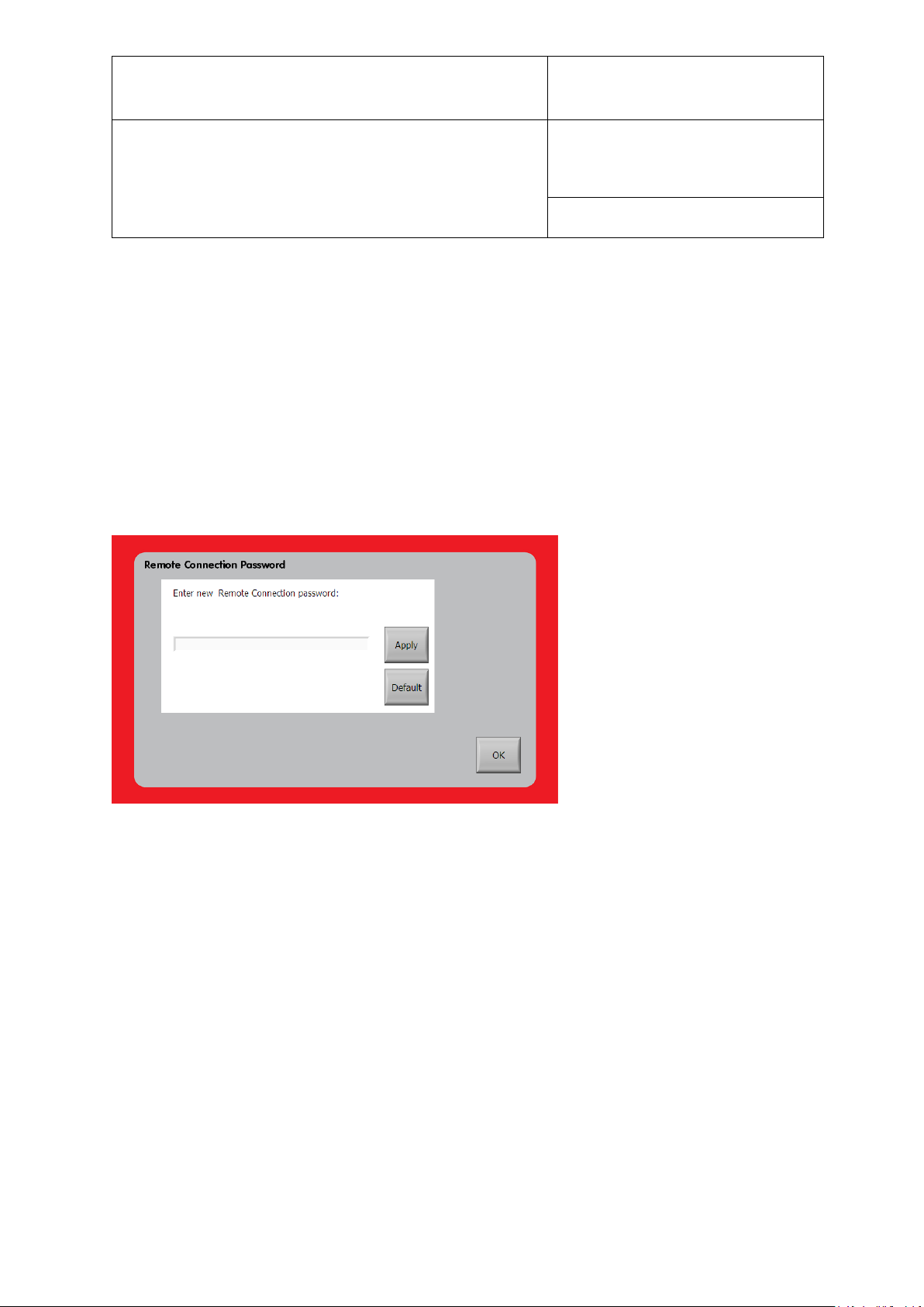
E-M-HG2-S-XL-V3.4
Rotronic AG
Bassersdorf, Switzerland
Instruction Manual
Instruction Manual for Software
Version 3.4
Document Type
Document title
Document code Unit
HygroGen2: Humidity and Temperature Generator
with AutoCal, Chilled Mirror External Reference, Remote
Screen Share, RemoteAPI and Range Extension options.
Page 59 of 101
traversal/port forwarding (port 5900) but configuration is required on your firewall and is
beyond the scope of this document. Contact your IT support department if you wish to set this
up.
To enable Remote Connection, go to the “Settings” drop-down menu on the “Settings” screen
and select “Remote (Screen Share)”. The functionality can be toggled on or off by the
“On”/“Off” button.
To set the VNC password requires configuration mode. Please press the “Password” button to
restart the HygroGen2. Once in Configuration Mode, reselect “Remote Connection” from the
Settings drop-down menu and then press “Password”.
Figure 38: Set Password
In normal Operational Mode, the “Default” button temporarily resets the VNC password to a
service default password, which will persist until the HygroGen2 is restarted. If in
Configuration Mode, pressing “Default” will permanently set the VNC password to the service
default password. You will need to set your password again via the “Password” button if this is
pressed.
To connect your VNC client to the HygroGen2, enter the Local Area Network IP address as the
server name in your VNC client, and the password as set in the previous section. You may
receive a warning that the connection is not encrypted.
© 2020; Rotronic AG E-M-HG2-S-XL-V3.4
Page 61
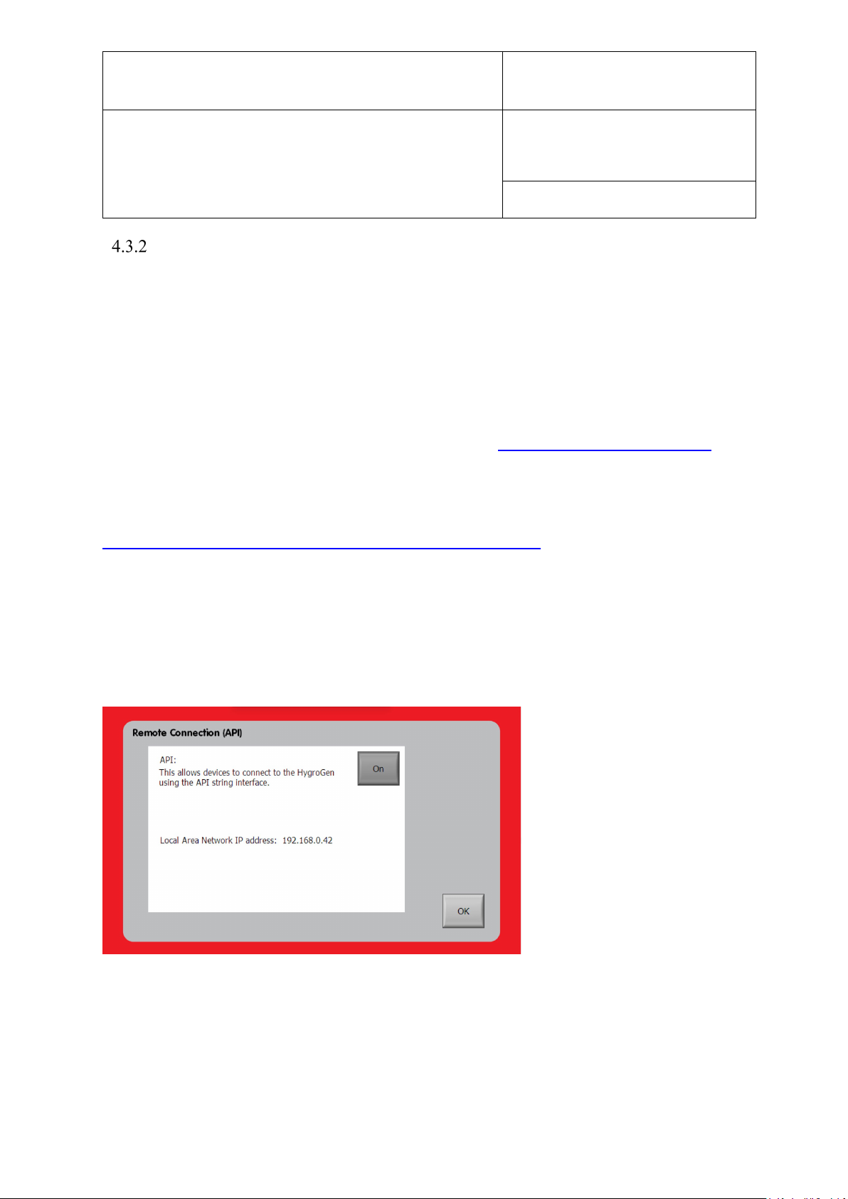
E-M-HG2-S-XL-V3.4
Rotronic AG
Bassersdorf, Switzerland
Instruction Manual
Instruction Manual for Software
Version 3.4
Document Type
Document title
Document code Unit
HygroGen2: Humidity and Temperature Generator
with AutoCal, Chilled Mirror External Reference, Remote
Screen Share, RemoteAPI and Range Extension options.
Page 60 of 101
RemoteAPI
The Remote Application Programming Interface (API) feature allows granular control and
logging of the HygroGen2 using external software via a set of TCP/IP strings commands over
the network. This allows the HG2 to connect to HW4 running on a PC, and integration with 3rd
party logging and calibration software platforms such as MBW’s Gecko logging software and
customised control software.
The feature requires the HygroGen2 to be connected to a network, and the instrument to be
appropriately configured for network access. See section Section 3.3.1 Network Settings.
The following description uses the Shell Client ‘putty.exe’ as an example command line
interface, which is available as a free download for PC or Mac.
https://www.chiark.greenend.org.uk/~sgtatham/putty/latest.html
Commands are issued on port 6341 in RAW TCP/IP format to the IP address of the
HygroGen2. Any bespoke client can be used which can issue commands in this format, e.g.
National Instruments LabView.
To enable Remote Connection, go to the “Settings” drop-down menu on the “Settings” screen
and select “RemoteAPI”. The functionality can be toggled on or off by the “On”/“Off” button.
Figure 39: RemoteAPI
Your remote-control device needs to be on the same Local Area Network (LAN) as your
HygroGen2. Off-site connections are possible from other networks using firewall traversal/port
forwarding (port 6341) but configuration is required on your firewall and is beyond the scope
of this document. Contact your IT support department if you wish to set this up.
© 2020; Rotronic AG E-M-HG2-S-XL-V3.4
Page 62
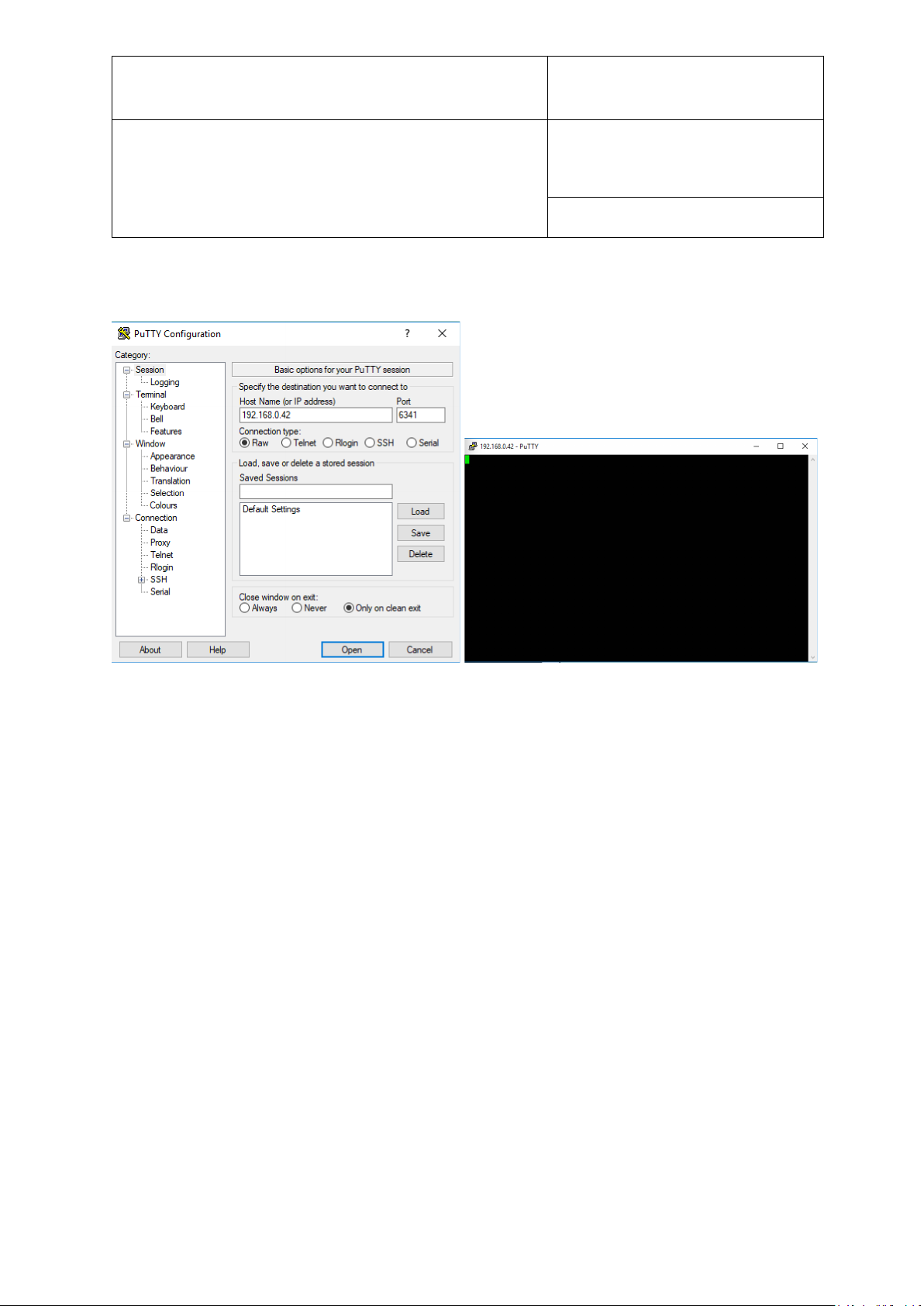
E-M-HG2-S-XL-V3.4
Rotronic AG
Bassersdorf, Switzerland
Instruction Manual
Instruction Manual for Software
Version 3.4
Document Type
Document title
Document code Unit
HygroGen2: Humidity and Temperature Generator
with AutoCal, Chilled Mirror External Reference, Remote
Screen Share, RemoteAPI and Range Extension options.
Page 61 of 101
Using the reported LAN IP address, establish a connection in RAW format on port 6341.
Figure 40: Putty – Example Command Line Interface
© 2020; Rotronic AG E-M-HG2-S-XL-V3.4
Page 63

E-M-HG2-S-XL-V3.4
Rotronic AG
Bassersdorf, Switzerland
Instruction Manual
Instruction Manual for Software
Version 3.4
Document Type
Document title
Expected
value
Reports value of chamber temperature in degrees Celsius (slow HC2-S-S
or MBW External Reference)*
Reports value of chamber humidity in %rh [as reported by control HC2-SS]
YYYY-MMDD hh-mm-ss
DesiccantHC2Sserial?
Document code Unit
HygroGen2: Humidity and Temperature Generator
with AutoCal, Chilled Mirror External Reference, Remote
Screen Share, RemoteAPI and Range Extension options.
Page 62 of 101
At the command prompt, you can issue any of the follow series of queries or commands, which
esentially mirror the touchscreen interface described in section 3.4.1 and section 4.2
Command
Temp? -5.00…60.00 Reports value of chamber temperature in degrees Celsius (fast PRT)
TempRef? -5.00…60.00
TempControl? 1,0 Reports whether chamber temperature control is on (1) or off (0)
TempControl=x 1,0 Sets chamber temperature control to be 'x' on (1) or off (0)
TempSP? -5.00…60.00 Reports value 'x' of chamber temperature set point in degrees Celsius
TempSP=x -5.00…60.00 Sets value 'x' of chamber temperature set point in degrees Celsius
TempStable? 1,0
RH? 0.0…99.0
RHRef? 0.0…99.0
RHControl? 1,0 Reports whether chamber humidity control is on (1) or off (0)
RHControl=x 1,0 Sets value 'x' of chamber humidity control to on (1) or off (0)
RHSP? 0.0…99.0 Reports value of chamber humidity set point in %rh
RHSP=x 0.0…99.0 Sets value 'x' of chamber humidity set point in %rh
RHStable? 1,0
Description
Reports whether chamber temperature is stable (1) [=green on interface] or
unstable (0) [=red on interface] within set criteria
Reports value of chamber humidity in %rh [as reported by selected
reference, either HC2-S-S or external MBW]*
Reports whether chamber humidity is stable (1) [=green on interface] or
unstable (0) [=red on interface] within set criteria
Time?
DesiccantDP? -90…0 Reports estimate of desiccant level in degrees Celsius (dew point)
DesiccantCell No. 1,2 Desiccant Cell in use. HG2-XL only (Cell1=1, Cell2=2)
WaterLevel? 0..100 Reports water level sensor reading in ml
HC2-SSerial? <text> Reports serial number of control HC2-S-S
<text> Reports serial number of desiccant HC2-S-S
Reports date/time
*note: these values will be with corrections applied if the MBW Reference is used, a correction
table has been entered, and applied and RH calculations are based on dew point (not RH).
© 2020; Rotronic AG E-M-HG2-S-XL-V3.4
Continued
Page 64

E-M-HG2-S-XL-V3.4
Rotronic AG
Bassersdorf, Switzerland
Instruction Manual
Instruction Manual for Software
Version 3.4
Document Type
Document title
Reports contents of reference information as entered in HygroGen2
interface. NB Not yet implemented.
Reports MBW external reference dew point in degrees Celsius (dew
point)
Reports MBW external reference dew point in degrees Celsius (dew
point) with applied corrections
Reports whether dew/frost layer is stable (1) or not (0) on MBW external
Passes command directly to MBW External Reference
(see MBW manual for list)
Document code Unit
HygroGen2: Humidity and Temperature Generator
with AutoCal, Chilled Mirror External Reference, Remote
Screen Share, RemoteAPI and Range Extension options.
Page 63 of 101
(RemoteAPI command list – continued)
Command Expected value Description
Version? <text> Reports HG2 firmware version
ControllerSerial? <text> Reports HG2 hardware controller serial number
Name? <text> Reports HG2 NetBios network name as configured in Network Settings
Reference? <text>
CorrApplied 1,0
Calculation 1,0
RefFile <text>
ExtRefSerial? <text> Reports model and serial number of external MBW reference
ExtRefTemp? -20.0…70.0 Reports MBW external temperature in degrees Celsius (uncorrected)
ExtRefDP? -20.0…70.0
ExtRefDPCorr? -20.0…70.0
ExtRefFP? -20.0…70.0
ExtRefRH? 0.0..99.0 Reports MBW external reference humidity in %rh (uncorrected)
ExtRefControl? 1,0
ExtRefStable? 1,0
Reports whether the internal control HC2-S or an external MBW
reference is configured to be the reference
Reports whether dew point corrections applied if MBW External
Reference is used. NB Not yet implemented.
Reports whether calculation is made on basis of RH or DP if MBW
External Reference is used. NB Not yet implemented.
Reports MBW external reference frost point in degrees Celsius (frost
point) (uncorrected)
Reports whether dew/frost control switched on (1) or off (0) on MBW
external reference
reference
E= <text>
Warning? <text> Reports any HG2 onscreen notifications, e.g. low water level
ProgramRun? 1,0 Reports whether if any programs running on HG2 (1 if yes, 0 if no)
Shutdown none Shuts down the HygroGen2
© 2020; Rotronic AG E-M-HG2-S-XL-V3.4
Page 65

E-M-HG2-S-XL-V3.4
Rotronic AG
Bassersdorf, Switzerland
Instruction Manual
Instruction Manual for Software
Version 3.4
Document Type
Document title
Document code Unit
HygroGen2: Humidity and Temperature Generator
with AutoCal, Chilled Mirror External Reference, Remote
Screen Share, RemoteAPI and Range Extension options.
Page 64 of 101
4.4 Range Extensions
Range extension allows set-points to be set down to -5 °C and 2%rh and up to 99%rh (between
10 °C and 45 °C).
The HygroGen2 will achieve these set-points individually but will be unable to reach some of
the combined conditions. For example, setpoints of -5°C and 2%rh can be set, but the
HygroGen2 will not achieve the condition. Typically, the minimum achievable Dew Point is 35 °C, but individual HygroGen2 performance will be dependent on chamber loading and
desiccant, ambient & instrument condition. See figure 41 for expected performance.
With the Humidity Range Extension, the HygroGen2 may be further configured to allow setpoints between 0 and 99.9 % RH (maximum 90 %RH below 10 °C). This is done from the
Service menu on the Service screen.
Please be aware that it may take a long time to reach set-points at these extremes of
temperature and humidity, and the unit may need to be individually adjusted to optimise
performance. Ambient conditions will affect the performance of the HygroGen2 at low
temperatures. Units that have not been serviced recently may not achieve low set-points.
Control HC2-Ss that are not specifically calibrated for low temperature & RH operation will
require characterisation and probably adjustment. Expert adjustment of the control PID
parameters may also be required. PID access is via the Service Menu, which is locked down for
standard operation. For further information please contact [email protected].
© 2020; Rotronic AG E-M-HG2-S-XL-V3.4
Page 66

E-M-HG2-S-XL-V3.4
Rotronic AG
Bassersdorf, Switzerland
Instruction Manual
Instruction Manual for Software
Version 3.4
Document Type
Document title
Document code Unit
HygroGen2: Humidity and Temperature Generator
with AutoCal, Chilled Mirror External Reference, Remote
Screen Share, RemoteAPI and Range Extension options.
Page 65 of 101
5 General Operational Considerations
Water in the Chamber
Before using the HygroGen2, check that there is no visible water inside the chamber. If the last
condition run by the HygroGen2 was at high humidity and the unit was not correctly shut down
(see below), condensation may have formed. Remove excess water using absorbent tissue and
initially run the HygroGen2 at an elevated temperature (40 °C) and low RH set-point to dry the
system before calibrations are performed.
Below Ambient Temperature Operation
If the chamber is cooling (or maintaining a temperature below ambient), then the heat pump
assembly inside the chamber will necessarily be below the chamber temperature. If the
humidity in the chamber is high, the cool heat pump assembly can bring the local air
temperature below the dew point, causing condensation to occur on the internal heat pump
assembly. If run under these conditions for extended periods, condensation will collect in the
chamber. This will not affect chamber performance within normal operating ranges (although it
will increase the time to achieve low humidity). Water in the chamber can be removed using an
absorbent tissue. Ensure the HygroGen2 is switched off before manually drying the chamber.
When operating the unit at high humidity and chamber temperatures of more than a few
degrees below ambient, the following procedure will minimise condensation in the chamber
during stabilisation:
1. Set the set-point temperature to approximately ambient.
2. Set the humidity set-point to 10 %rh and allow the HygroGen2 to stabilise.
3. Set the temperature set-point to that desired and allow the HygroGen2 to stabilise.
4. Wait for the Humidity reading to fully stabilise (this may take 15-20 minutes).
It is recommended that the chamber door is not opened when the chamber temperature is below
the ambient temperature as water vapour from the atmospheric air introduced will condense out
into the chamber. The dehumidification of the chamber takes longer at lower chamber
temperatures.
© 2020; Rotronic AG E-M-HG2-S-XL-V3.4
Page 67
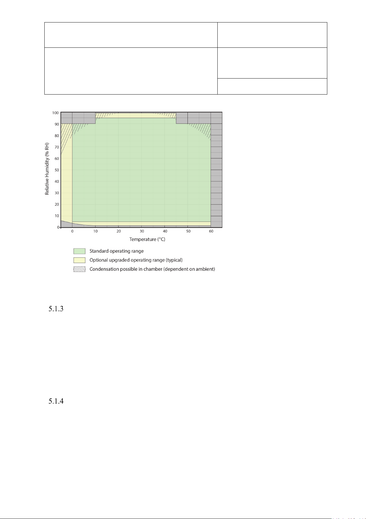
E-M-HG2-S-XL-V3.4
Rotronic AG
Bassersdorf, Switzerland
Instruction Manual
Instruction Manual for Software
Version 3.4
Document Type
Document title
Document code Unit
HygroGen2: Humidity and Temperature Generator
with AutoCal, Chilled Mirror External Reference, Remote
Screen Share, RemoteAPI and Range Extension options.
Page 66 of 101
Figure 41: Humidity Map – Standard and Extended Ranges
Above Ambient Temperature Operation
At high temperature and high relative humidity conditions, it is necessary to allow the unit to
stabilise to ensure minimal condensation. It is recommended that, for making measurements
over 45 °C and 80 %rh, the HygroGen2 temperature be permitted to equilibrate for 20 minutes
before high humidity is introduced. It is also recommended that, under these conditions, the
desired RH level is achieved in incremental steps, allowing stabilisation at each step. If the unit
is operated at high temperature and high humidity for prolonged periods, it is strongly
recommended that the chamber is thoroughly dehumidified prior to switching the unit off.
Probe Insertion Depth
When adjusting or calibrating probes against a reference, make sure that the insertion depth of
each instrument is the same for each probe. Using the same immersion depth substantially
reduces the effect of any temperature and humidity gradients in the chamber.
The immersion depth of any probe inserted in the HygroGen2 should be within the limits of
100-150 mm (4-6”), measured from the inner side of the door. This will reduce the effect of
room temperature via stem conduction on the probe.
© 2020; Rotronic AG E-M-HG2-S-XL-V3.4
Page 68

E-M-HG2-S-XL-V3.4
Rotronic AG
Bassersdorf, Switzerland
Instruction Manual
Instruction Manual for Software
Version 3.4
Document Type
Document title
Document code Unit
HygroGen2: Humidity and Temperature Generator
with AutoCal, Chilled Mirror External Reference, Remote
Screen Share, RemoteAPI and Range Extension options.
Page 67 of 101
Protective Filters
Make sure you allow appropriate extra time for probes with particular protective filters. These
probes require a longer time than the HygroGen2 to stabilise.
The Trend Screen displays the measured values over time, so the user can observe whether the
HygroGen2 is stable within the acceptance criteria.
Low Water Level Alarm
The unit will inform the operator if the water level in the reservoir is too low with a visual
“Low Water Level” prompt on the controller screen.
If the water level in the saturator falls below 20 ml, humidification is disabled to prevent
damage to the humidifier. Humidification will not be re-activated until the water level is
restored.
Replenish the reservoir according to the instructions in section 2.4.
Note: If the “Low Water Level” message appears on the controller screen during use, the
HygroGen2 can be topped up with 50 ml of demineralised water. This will bring the total water
content of the reservoir to approximately 80 ml.
Water Level Indicator Calibration
The water level sensor may behave differently for different qualities of water. To ensure
accuracy of the water level indicator, periodic calibration is advised. To access this feature, go
to the Settings Screen and select “Water Level” from the “Settings” drop-down menu. Follow
the on-screen instructions.
© 2020; Rotronic AG E-M-HG2-S-XL-V3.4
Page 69
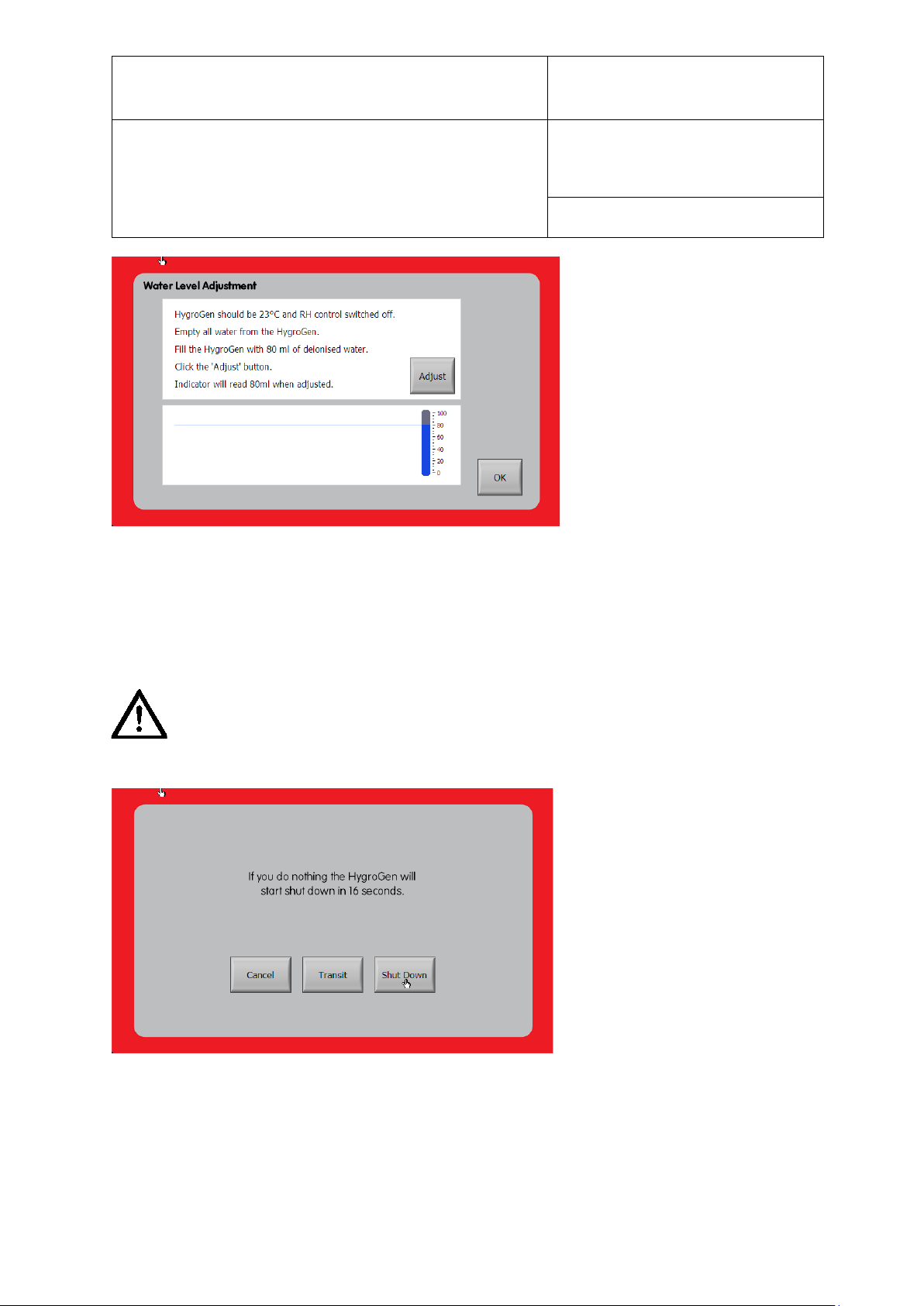
E-M-HG2-S-XL-V3.4
Rotronic AG
Bassersdorf, Switzerland
Instruction Manual
Instruction Manual for Software
Version 3.4
Document Type
Document title
Figure 43: Shutdown Screen
Document code Unit
HygroGen2: Humidity and Temperature Generator
with AutoCal, Chilled Mirror External Reference, Remote
Screen Share, RemoteAPI and Range Extension options.
Figure 42: Water Level Adjustment
Page 68 of 101
5.2 Switching off the HygroGen2
There are two Shutdown procedures; these are presented after you press the onscreen power button. It is important that these are observed; instrument faults
attributable to incorrect Shutdown are not covered by the warranty.
© 2020; Rotronic AG E-M-HG2-S-XL-V3.4
Page 70
E-M-HG2-S-XL-V3.4
Rotronic AG
Bassersdorf, Switzerland
Instruction Manual
Instruction Manual for Software
Version 3.4
Document Type
Document title
Document code Unit
HygroGen2: Humidity and Temperature Generator
with AutoCal, Chilled Mirror External Reference, Remote
Screen Share, RemoteAPI and Range Extension options.
Page 69 of 101
Shut Down
In normal circumstances use “Shutdown”. This dries the chamber to prevent residual water and
isolates the humidifier from the chamber. Once correctly shutdown, the HygroGen2 is in a
suitable condition for short- to medium-term periods without use. It is also put into a condition
where it can be moved carefully in a horizontal position (e.g. on a trolley) to a different
location (say, within a building).
Shutdown Procedure:
1. Press the “Power Off” button on-screen.
2. Select “Shut Down”.
3. Allow the HygroGen2 to shut down. The HygroGen2 will isolate the humidifier
and cool/dry to ensure excess water is removed. This may take several minutes.
DO NOT switch off at the wall before the HygroGen2 has shut down.
DO NOT switch off at the back of the HygroGen2 before it has shut down.
Transit
Use “Transit” to shut down and condition the HygroGen2 if the unit is to be transported or
stored for an extended period. The HygroGen2 will ask for the unit to be emptied of water. It
will isolate the humidifier from the chamber and then cool/dry the chamber to ensure excess
water is removed. This process may take several minutes.
Transit Procedure
1. Press the “Power Off” button on-screen.
2. Select “Transit”.
3. Empty water as prompted on-screen.
4. Allow the HygroGen2 to shut down. The HygroGen2 will isolate the humidifier and cool/dry to
ensure excess water is removed. This may take several minutes.
HygroGen2 will not switch off if the water is not emptied as requested!
DO NOT switch off at the wall before the HygroGen2 has shut down. Failure to
do this may cause software corruption if running firmware version 1.x.
© 2020; Rotronic AG E-M-HG2-S-XL-V3.4
Page 71
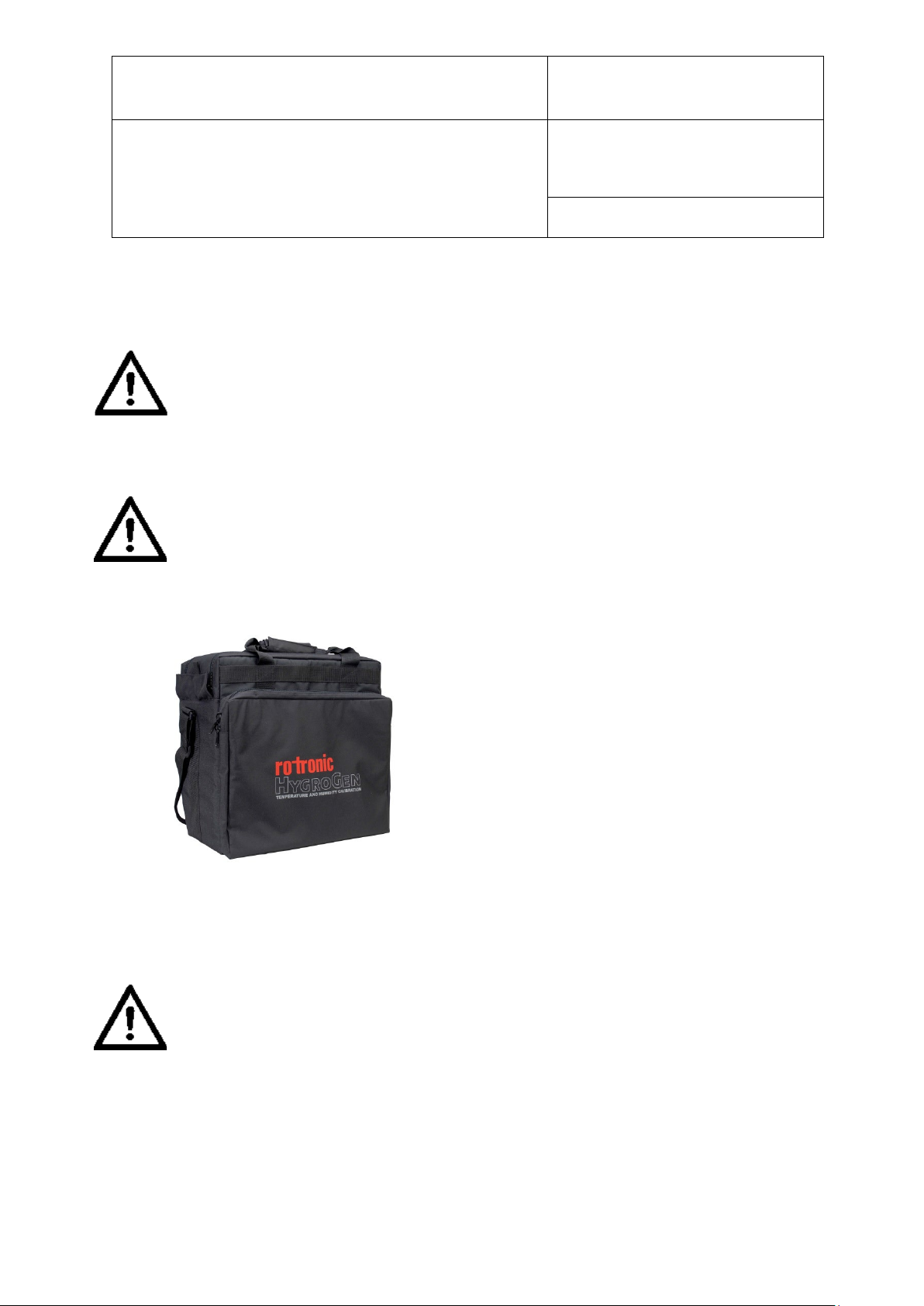
E-M-HG2-S-XL-V3.4
Rotronic AG
Bassersdorf, Switzerland
Instruction Manual
Instruction Manual for Software
Version 3.4
Document Type
Document title
Figure 44: HG-TB Transit Bag
Document code Unit
HygroGen2: Humidity and Temperature Generator
with AutoCal, Chilled Mirror External Reference, Remote
Screen Share, RemoteAPI and Range Extension options.
5.3 Preparing the Unit for Transit or Storage
Shut down the HygroGen2 according to the Transit Shutdown Procedure above.
If the HygroGen2 needs to be shipped, always use the original double-layer cardboard
packaging. The HG-TB transit bag is suitable for hand carrying only; for air or truck
shipping, supplement the HG-TB with a sturdy cardboard box with at least 100mm of
foam or other shock protection material surrounding all sides.
When shipping involves air transportation, either remove the chamber door, or at least
one probe bung, to prevent condensation of any residual moisture when exposed to
low aircraft hold temperatures.
Even having completely emptied the water reservoir, after transportation there may be
a small amount of residual water that has drained into the chamber from the pipework.
This is normal and can be simply wiped out with a lint-free cloth.
Page 70 of 101
© 2020; Rotronic AG E-M-HG2-S-XL-V3.4
Page 72

E-M-HG2-S-XL-V3.4
Rotronic AG
Bassersdorf, Switzerland
Instruction Manual
Instruction Manual for Software
Version 3.4
Document Type
Document title
Document code Unit
HygroGen2: Humidity and Temperature Generator
with AutoCal, Chilled Mirror External Reference, Remote
Screen Share, RemoteAPI and Range Extension options.
Page 71 of 101
6 HW4 Embedded
HygroGen2 comes with HW4 ROTRONIC device control software on its embedded PC. This
provides the user with access to HW4 functionality to access ROTRONIC USB devices
without the need for a separate PC.
HW4 features include:
Psychrometric conversions
Instrument configuration
Data acquisition
Measurement display and graphing
Calibration and adjustment
HW4 does not work with other manufacturers’ USB probes.
6.1 HW4 Set Up and Getting Started
For full functionality, HW4 requires an external monitor, keyboard and mouse to be
connected to the HygroGen2 (see section 7). To start HW4, touch the HW4 icon. Drag the
HW4 window onto a second monitor if available.
Any ROTRONIC HC2-S probes that are connected to the HygroGen2’s USB ports using a
ROTRONIC service cable, can be connected to HW4 using the “Search for USB Masters”
command. For a full overview of the use and features of HW4, please refer to the full HW4
manual. This can be obtained from the Downloads section of www.rotronic.com.
© 2020; Rotronic AG E-M-HG2-S-XL-V3.4
Page 73
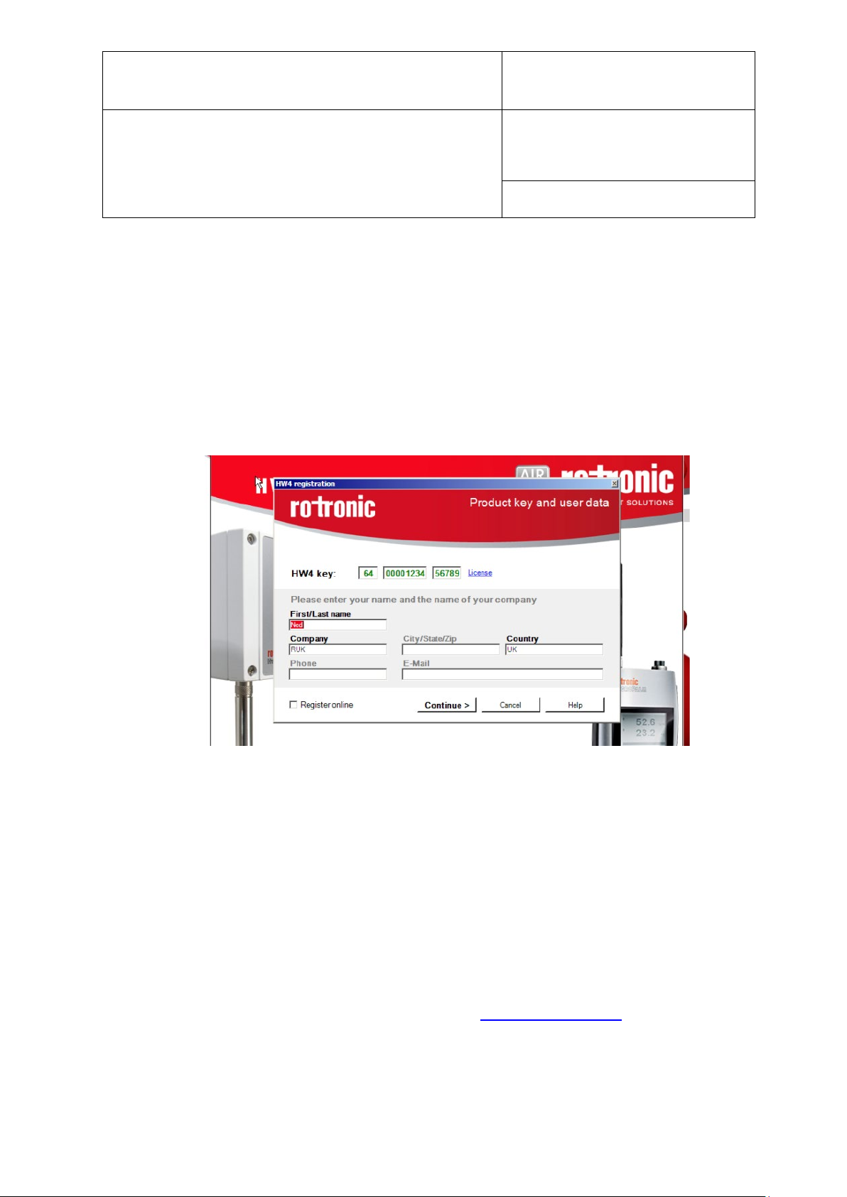
E-M-HG2-S-XL-V3.4
Rotronic AG
Bassersdorf, Switzerland
Instruction Manual
Instruction Manual for Software
Version 3.4
Document Type
Document title
Document code Unit
HygroGen2: Humidity and Temperature Generator
with AutoCal, Chilled Mirror External Reference, Remote
Screen Share, RemoteAPI and Range Extension options.
Page 72 of 101
6.2 HW4 Installation and Registration
HW4 is preinstalled and activated during HygroGen2 manufacture. The HW4 version number
can be identified via the Settings screen of the HygroGen2. Select the “Support” drop-down
menu and select HygroGen2 Info; please have this information available in the event that you
require technical support.
You may also need the unique HW4 installation key which can be found as follows:
i. On the HygroGen2, launch HW4. Click Registration on the startup screen.
ii. Make a note of the serial number.
iii. Click Cancel and close HW4.
To register your HW4 software and to assign your full contact details, visit
www.rotronic.com and go to the “Software” Section. Software registration will ensure that
you receive full support and notification of upgrades available. Do not try to register online
via the HygroGen2 interface as this will not work.
6.3 HW4 Support
Support for HW4 is available via email. Please contact [email protected] including your
full contact details, the HygroGen2 serial number and HW4 product key, and a description of
your query or problem. You will receive a response within a maximum of two working days.
© 2020; Rotronic AG E-M-HG2-S-XL-V3.4
Page 74
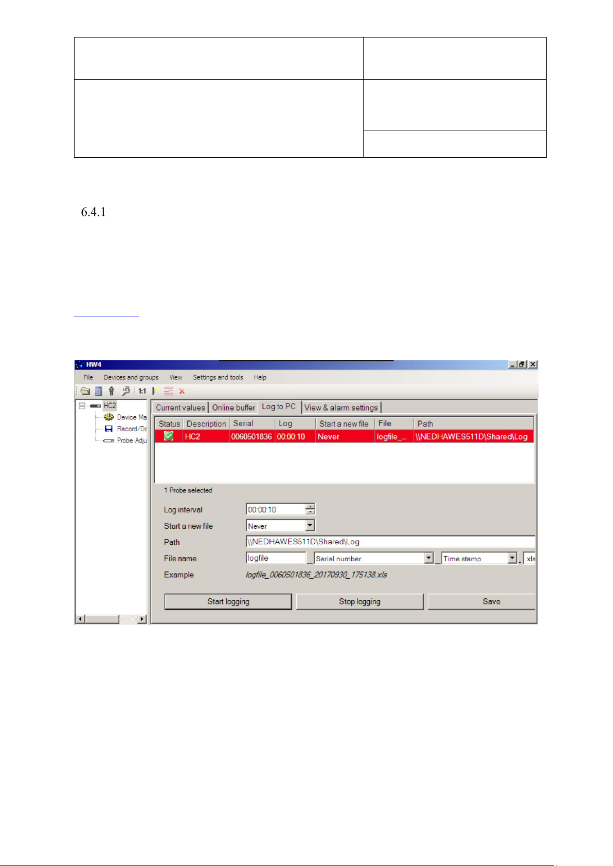
E-M-HG2-S-XL-V3.4
Rotronic AG
Bassersdorf, Switzerland
Instruction Manual
Instruction Manual for Software
Version 3.4
Document Type
Document title
Document code Unit
HygroGen2: Humidity and Temperature Generator
with AutoCal, Chilled Mirror External Reference, Remote
Screen Share, RemoteAPI and Range Extension options.
Page 73 of 101
6.4 Data Logging in HW4
Test Instrument Data
HW4 can only log HC2 or HC2A probes. It is not compatible with HCD probes.
HW4 can log to an inserted USB stick or to a network file share.
In HW4, click the instrument under test in the device tree and select Log to PC.
Choose either a local path to a USB stick, or configure a network file share, as described in
Section 3.4.9, and enter the required server path in the ‘Path’ field in HW4. For further details
on HW4, please see ROTRONIC HW4 documentation.
© 2020; Rotronic AG E-M-HG2-S-XL-V3.4
Page 75
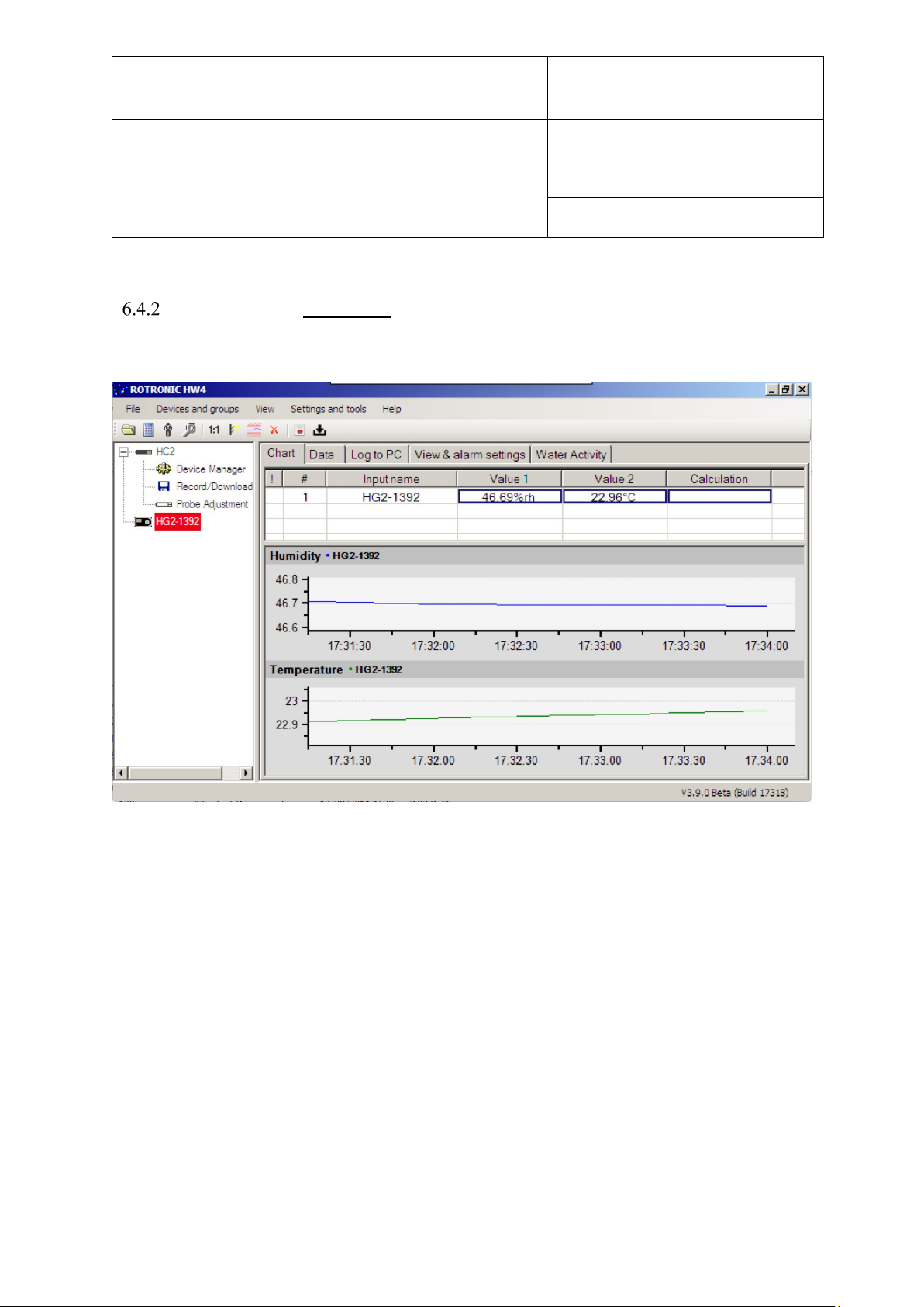
E-M-HG2-S-XL-V3.4
Rotronic AG
Bassersdorf, Switzerland
Instruction Manual
Instruction Manual for Software
Version 3.4
Document Type
Document title
Document code Unit
HygroGen2: Humidity and Temperature Generator
with AutoCal, Chilled Mirror External Reference, Remote
Screen Share, RemoteAPI and Range Extension options.
Page 74 of 101
Control HC2-S [HW4v3.9]
As of firmware version 3.9, HW4 can see and log the HygroGen2 control HC2-S.
HW4 automatically detects the HygroGen2 and adds it to the device tree. Should you not
wish for it to be listed, delete it in the proscribed fashion as detailed in HW4 documentation.
© 2020; Rotronic AG E-M-HG2-S-XL-V3.4
Page 76
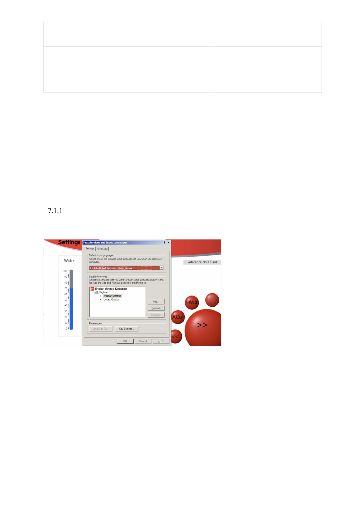
E-M-HG2-S-XL-V3.4
Rotronic AG
Bassersdorf, Switzerland
Instruction Manual
Instruction Manual for Software
Version 3.4
Document Type
Document title
Document code Unit
HygroGen2: Humidity and Temperature Generator
with AutoCal, Chilled Mirror External Reference, Remote
Screen Share, RemoteAPI and Range Extension options.
Page 75 of 101
7 External PC Peripherals
7.1 USB Keyboard and Mouse
All standard user functions may be accessed using the HygroGen2 touch screen. However, if
desired, any standard USB keyboard and mouse may be plugged in via front or rear USB
ports to facilitate operation.
This is particularly useful for operating the embedded HW4 ROTRONIC device control
software.
International Keyboard Layouts
Different international keyboards can be configured for the HygroGen2 via the Settings Page,
“Settings” drop-down menu and selecting “Keyboard Setup”.
A standard Windows Keyboard Control Panel appears which can then be configured to use
your keyboard layout of choice.
© 2020; Rotronic AG E-M-HG2-S-XL-V3.4
Page 77

E-M-HG2-S-XL-V3.4
Rotronic AG
Bassersdorf, Switzerland
Instruction Manual
Instruction Manual for Software
Version 3.4
Document Type
Document title
Document code Unit
HygroGen2: Humidity and Temperature Generator
with AutoCal, Chilled Mirror External Reference, Remote
Screen Share, RemoteAPI and Range Extension options.
Page 76 of 101
7.2 External Monitor
Running the embedded HW4 software on the integrated screen is possible, but not practical,
so an external DVI monitor connection is available on the rear of the HygroGen2. DVI
monitors are widely available; no special configuration or size is required.
To configure the DVI monitor, use the following procedure:
1. Connect the HygroGen2 to the DVI monitor.
2. Plug in the USB keyboard and mouse.
3. Go to the Settings screen on the HygroGen2.
4. Select Monitor Set-Up – “Display Properties” appears.
5. Click on monitor 2 icon.
6. Select “Extend my Windows desktop onto this monitor”.
7. Click on “Apply”.
8. Screen resolution should be adjusted to suit the monitor connected.
9. Apply any changes and click “OK” to exit Display Properties.
10. Click on the HW4 icon.
11. HW4 will open on the HygroGen2 screen.
12. Using the mouse, drag the HW4 window so that it displays on the monitor.
13. You can now size the HW4 window to suit the connected monitor.
© 2020; Rotronic AG E-M-HG2-S-XL-V3.4
Page 78
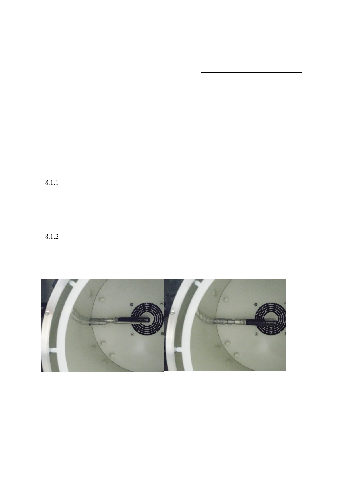
E-M-HG2-S-XL-V3.4
Rotronic AG
Bassersdorf, Switzerland
Instruction Manual
Instruction Manual for Software
Version 3.4
Document Type
Document title
Figure 45: HG2-XL Control HC2 and PT100 Sensor, and with latter removed
Document code Unit
HygroGen2: Humidity and Temperature Generator
with AutoCal, Chilled Mirror External Reference, Remote
Screen Share, RemoteAPI and Range Extension options.
Page 77 of 101
8 Servicing and Maintenance
8.1 Control HC2-S Calibration
The control HC2-S may need to be removed for calibration. To minimise HygroGen2
downtime, alternative calibrated probes can be fitted in place of the existing probe. When
using the HC2-S control probe as the reference in AutoCal, the serial number of the probe
used will automatically be recorded within the calibration certificate.
Removing Control HC2-S HG2-S
To remove the control HC2-S, turn off the HygroGen2 control and remove the door. Reach
into the chamber and unscrew the HC2-S from its mounting connector. Take care not to cross
the threads on the collar when refitting.
Removing Control HC2-S HG2-XL
To remove the control HC2-S, turn off the HygroGen2-XL control and open the door. First,
remove the Fast PT100 sensor, by gently pulling on the Lemo connector sleeve. Then do the
same for the HC2-S control HC2-S. Unscrew the HC2-S from its housing.
© 2020; Rotronic AG E-M-HG2-S-XL-V3.4
Page 79
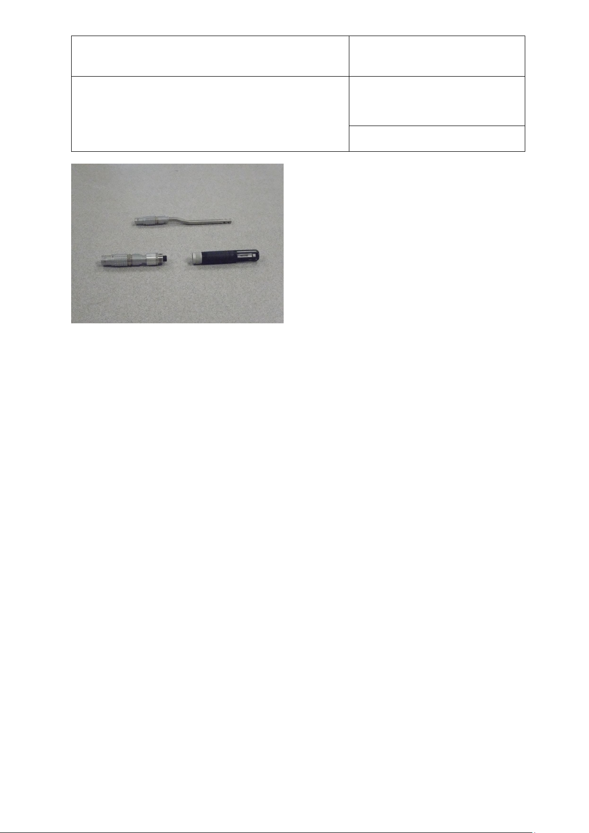
E-M-HG2-S-XL-V3.4
Rotronic AG
Bassersdorf, Switzerland
Instruction Manual
Instruction Manual for Software
Version 3.4
Document Type
Document title
Figure 46: Control PT100 and HC2 separated from Lemo housing
Document code Unit
HygroGen2: Humidity and Temperature Generator
with AutoCal, Chilled Mirror External Reference, Remote
Screen Share, RemoteAPI and Range Extension options.
Page 78 of 101
When replacing, take care not to cross the threads on the collar when refitting. Line up the
Lemo connectors so the red spot faces forward and push back into place, first the HC2-S,
then the PT100 sensor.
8.2 Desiccant
The HygroGen2 uses a desiccant when lowering humidity in the chamber. The desiccant
condition is shown within the Settings screen. This shows an approximate indication of the
dew point within the dryer cell.
If the HygroGen2 does not reach low RH set-points promptly, check the desiccant condition
and replace as required.
The measured desiccant value is established when the dryer is active and a flow of air from
the desiccant cell is passing over the desiccant sensor; this value is held when the dryer is
active to provide the user with an indication of the desiccant condition even if the dryer is not
used. To update the value, run the HygroGen2 on the lowest RH set-point (5 %rh) for at least
5 minutes.
© 2020; Rotronic AG E-M-HG2-S-XL-V3.4
Page 80
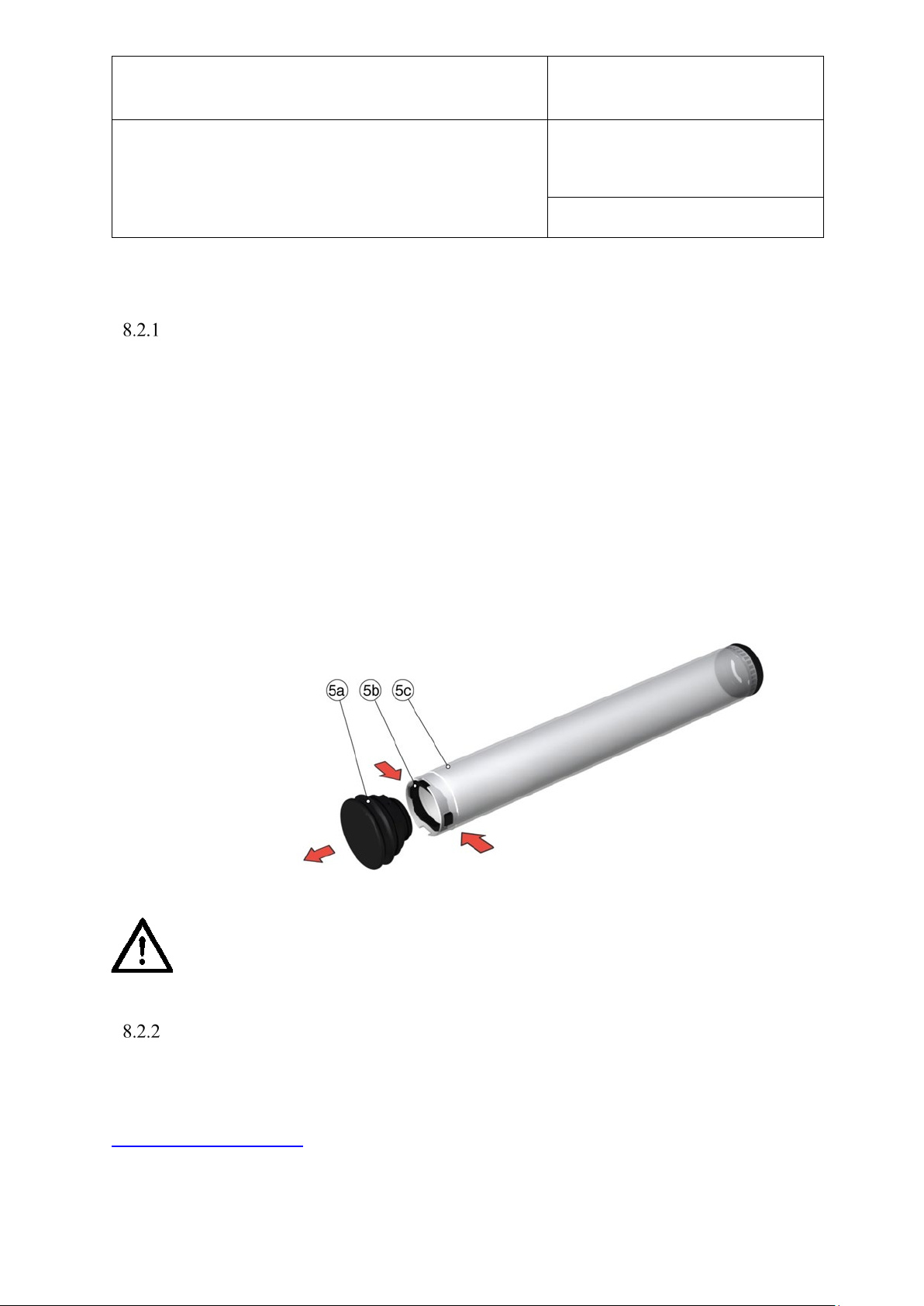
E-M-HG2-S-XL-V3.4
Rotronic AG
Bassersdorf, Switzerland
Instruction Manual
Instruction Manual for Software
Version 3.4
Document Type
Document title
5a) Cell cap
Figure 47: Desiccant Cell
Document code Unit
HygroGen2: Humidity and Temperature Generator
with AutoCal, Chilled Mirror External Reference, Remote
Screen Share, RemoteAPI and Range Extension options.
Page 79 of 101
Changing Desiccant
Remove the desiccant cell from the HygroGen2 by pulling firmly on the cell cap
(Figure 1(5)). The cell is held in place securely to maintain an air-tight seal; a gentle twist
will help removal. Changing the desiccant should be undertaken in a ventilated area.
Observing the diagram below (Figure 36), remove the cap and pour out the used desiccant
material and replace with new or regenerated material. Avoid exposing the replacement
desiccant unduly to the atmosphere.
Ensure that the cell is filled with as much desiccant as possible to ensure there are no air
gaps. Remember to replace the foam insert (that fits between the cell cap and the desiccant)
before replacing the cell cap and spring clip. Application of Krytox grease on the desiccant
cell cap “O” ring will help ease removal and refitting.
5b) Retaining clip
5c) Cell body
Caution: Do not use dusty desiccants as the dust may be passed into the
chamber.
Choice of Desiccant
The HygroGen2 is supplied from the factory filled with molecular sieve desiccant. Molecular
sieve is preferred due to its higher performance in all temperature and humidity conditions
and is longer lasting and can be regenerated through heating. Other desiccants including selfindicating silica gel and drierite can be used if desired; for further information, please contact
[email protected]. Dusty desiccants should be avoided as particles may be passed
into the HygroGen2 chamber. Replace or regenerate the desiccant whenever the drying
performance of the HygroGen2 is deteriorating.
© 2020; Rotronic AG E-M-HG2-S-XL-V3.4
Page 81

E-M-HG2-S-XL-V3.4
Rotronic AG
Bassersdorf, Switzerland
Instruction Manual
Instruction Manual for Software
Version 3.4
Document Type
Document title
Document code Unit
HygroGen2: Humidity and Temperature Generator
with AutoCal, Chilled Mirror External Reference, Remote
Screen Share, RemoteAPI and Range Extension options.
Page 80 of 101
Material Safety Sheets for the desiccants supplied by ROTRONIC are available on request.
Regeneration of Molecular Sieve Desiccant
It is possible to regenerate molecular sieve desiccant by heating it in a ventilated oven at
about 175°C for 5 hours and then allowing it to cool in a sealed container. Details of the
procedure are beyond the scope of this document. The effectiveness of the drying process and
the resulting performance of desiccant will affect the performance of the HygroGen2
Alternatively, replacement new desiccant can be ordered from ROTRONIC. Please contact
your local dealer.
8.3 HygroGen2 Cleaning
Prior to all servicing and maintenance procedures, the IEC mains cable at the rear of the
HygroGen2 should be disconnected from the electrical mains supply.
External surfaces
The external surfaces of the HygroGen2 may be cleaned with a lint-free cloth dampened with
a mild soap solution. Care must be taken not to allow fluids into any of the apertures on the
unit.
Air Inlet Filters – HG2-S
The fan inlet filter can be cleaned using a vacuum cleaner applied to the exterior of the
HG2-S side grill to remove any particulates. The filter material is replaced during servicing.
Air Inlet Filters – HG2-XL
The two air inlet filters on the back of the HG2-XL can be removed by unclipping the filter
housing, and the plastic filters can be washed under a tap and replaced when thoroughly dry.
© 2020; Rotronic AG E-M-HG2-S-XL-V3.4
Page 82
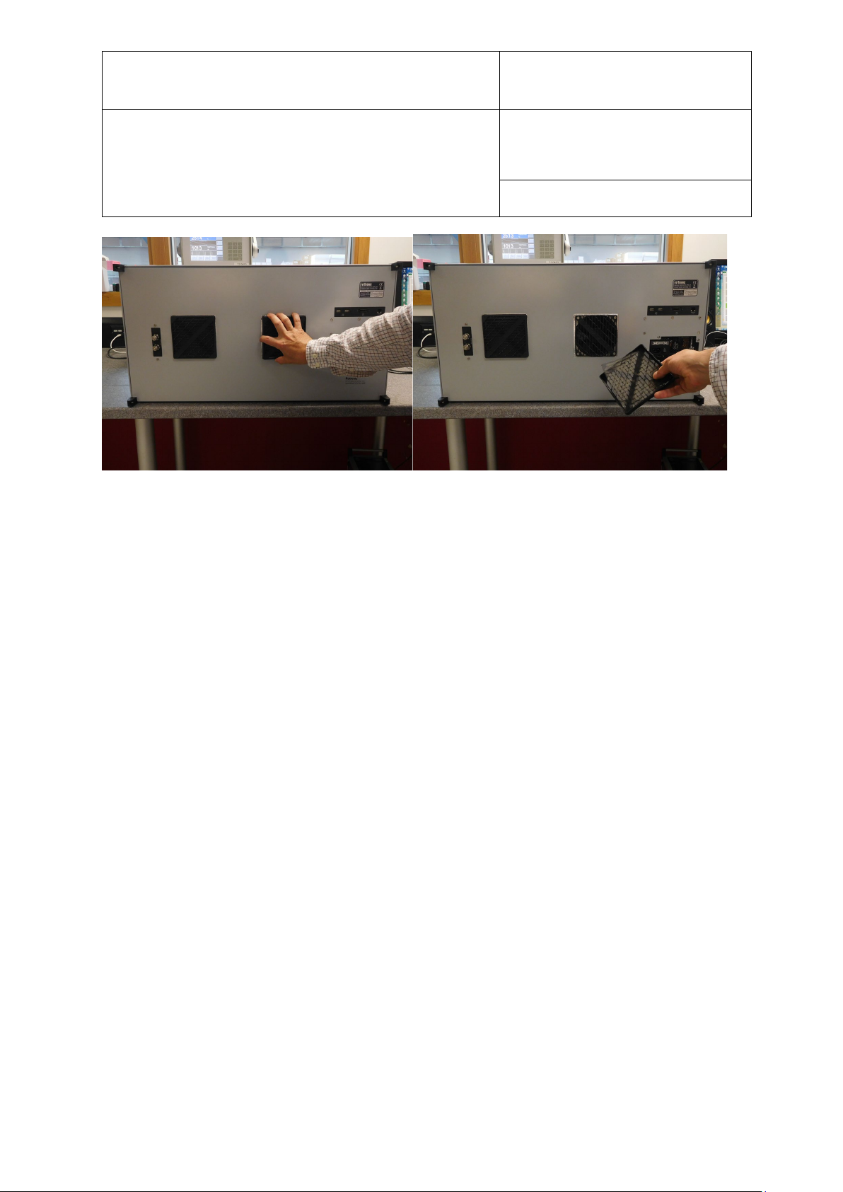
E-M-HG2-S-XL-V3.4
Rotronic AG
Bassersdorf, Switzerland
Instruction Manual
Instruction Manual for Software
Version 3.4
Document Type
Document title
Figure 48: HG2-XL Air inlet filter removal
Document code Unit
HygroGen2: Humidity and Temperature Generator
with AutoCal, Chilled Mirror External Reference, Remote
Screen Share, RemoteAPI and Range Extension options.
Page 81 of 101
© 2020; Rotronic AG E-M-HG2-S-XL-V3.4
Page 83
E-M-HG2-S-XL-V3.4
Rotronic AG
Bassersdorf, Switzerland
Instruction Manual
Instruction Manual for Software
Version 3.4
Document Type
Document title
Document code Unit
HygroGen2: Humidity and Temperature Generator
with AutoCal, Chilled Mirror External Reference, Remote
Screen Share, RemoteAPI and Range Extension options.
Page 82 of 101
Chamber
Periodically, it is recommended that the internal surfaces of the HygroGen2 chamber sleeve
are inspected and wiped clean of any visual residues using a lint-free cloth moistened with
demineralised water. Care should be taken to avoid mechanical damage to the control probe
and sampling tubes inside the chamber.
Purging internal pipes
Some humidity instruments are used in environments where chemical contaminants may be
present. Should these transfer to the HygroGen2, this may result in drift of the RH control
probe, which would become apparent during calibration. To purge the internal pipe work and
chamber of the HygroGen2, replace the desiccant with Granular Activate Charcoal (GAC)
and run the unit at 40°C and 5%rh for 6 hours. Place a sock of GAC in the HygroGen
chamber and run the unit at 60°C and 80%RH for 12 hours. Any volatile compounds within
the HygroGen2 will be absorbed into the GAC.
8.4 Annual Servicing of HygroGen2
The unit does not require routine user maintenance beyond that described in this Section.
For optimum performance, ROTRONIC recommends that the HygroGen2 is serviced every 12 months at
an approved HygroGen2 service centre, details of which can be found in Appendix C2 of this manual.
Under no circumstance should the unit be opened by personnel unauthorised by
the manufacturer. Doing so will void the manufacturer’s warranty and expose
potentially dangerous electrical hazards.
© 2020; Rotronic AG E-M-HG2-S-XL-V3.4
Page 84

E-M-HG2-S-V3.4
Rotronic AG
Bassersdorf, Switzerland
Instruction Manual for Software
Version 3.4
Document Type
Document code Unit
HygroGen2 Humidity and Temperature Generator:
Instruction Manual
Appendix
Document title
Page 83 of 101
A1: Calibration Reference Options
Various calibration references can be used with the HygroGen2. These include the internal
control probe, other RH probes, dew point chilled mirrors and platinum resistance
thermometers (PRTs).
For traceable calibration, these references are themselves calibrated by accredited
laboratories traceable to national standards.
For more information, please refer to The Guide to Uncertainty of Measurements (GUM)
published by the UK National Physical Laboratory (or equivalent national standards
documentation) and ISO/IEC 17025:2005 “General Requirements for the Competence of
Testing and Calibration Laboratories”.
Appendix D1 provides examples of uncertainty budgets for the HygroGen2 when using
different calibration references. These are for guidance only and ROTRONIC accepts no
liability in relation to their use.
A1.1 Internal RH Probe Reference
The display values on the HygroGen2 (which are derived from the control probe - as
described in Appendix A2) can be used as the reference.
Advantages:
No supplementary instruments are required.
Fastest response - control is based on the reference value.
Stability during calibration – the reference is continually optimising the control value.
The reference probe can be easily replaced with another calibrated probe.
HC2-S probes have the facility to be adjusted to agree with a calibration reference, meaning no
corrections of the HygroGen2 display value need to be made in routine use.
Disadvantages:
RH probes can drift over time, so regular checks need to be performed to achieve best
measurement capability and a larger drift component included in an overall uncertainty
calculation.
Probe characteristics, such as hysteresis or temperature coefficients, must be included within
the overall uncertainty budget.
RH probes are less accurate than chilled mirrors.
Using the internal probe as your reference provides the most convenient option, but routine
checks of the probe’s stability are required to ensure the quality of the calibration. Interim
calibration checks against a traceable reference (e.g. ROTRONIC non-saturated salt
© 2020; Rotronic AG E-M-HG2-S-XL-V3.4
Page 85

E-M-HG2-S-V3.4
Rotronic AG
Bassersdorf, Switzerland
Instruction Manual for Software
Version 3.4
Document Type
Document code Unit
HygroGen2 Humidity and Temperature Generator:
Instruction Manual
Appendix
Document title
Page 84 of 101
solutions) should be carried out regularly and the results recorded in a probe calibration
history.
Annual recalibration of the control probe by an accredited laboratory should be the minimum
calibration regime. Interim calibration checks in combination with the annual calibration
results will allow the key drift component of an uncertainty budget to be defined and
documented.
A1.2 External RH Probe Reference
Any RH instrument placed through the HygroGen2 door can be used as the reference. This
may be desired if your Quality System employs a particular RH probe with a long history. It
may not be desirable to adjust this probe and use it as the control probe – a separate adjusted
control probe may be more convenient.
The same disadvantages apply when using an external RH probe as a reference as when using
the RH control probe: i.e. accuracy, susceptibility to drift, hysteresis, regular calibration
requirement.
A1.3 Chilled Mirror Reference
To reduce calibration uncertainty, a chilled mirror instrument can be employed as the
reference. This type of instrument is generally accepted as a secondary humidity transfer
standard. Instruments should be maintained with an accredited (ISO 17025) calibration
certificate. A chilled mirror can be used to validate the HygroGen2 calibration before and
after on-site calibration using the internal RH probe as a reference.
Chilled mirrors measure dew point and is the temperature at which dew, or frost will form on
a surface. Relative humidity can be derived from this value with a corresponding temperature
measurement.
There are two types: an all-in-one probe which can be inserted through the HygroGen2 door,
with integrated PRT temperature probe e.g., Michell S8000 Remote, or an external sampling
head, for which the HygroGen2 external sample loop is employed (see section below).
Advantages of chilled mirror references:
Best measurement capability.
Instruments do not drift significantly.
Operates over a broad range of humidity conditions.
Disadvantages:
© 2020; Rotronic AG E-M-HG2-S-XL-V3.4
Page 86

E-M-HG2-S-V3.4
Rotronic AG
Bassersdorf, Switzerland
Instruction Manual for Software
Version 3.4
Document Type
Document code Unit
HygroGen2 Humidity and Temperature Generator:
Instruction Manual
Appendix
Document title
Regular mirror cleaning is required to maintain best possible performance.
Mirror measuring heads generate heat when cooling the mirror. Chilled mirror probes fitted
through the HygroGen2 door can introduce temperature gradients.
For external measuring heads at dew points above ambient conditions, sample lines must be
heated to avoid condensation which can introduce instability.
Chilled mirrors may be more expensive to calibrate than RH probes.
Longer stabilisation time.
Page 85 of 101
Without doubt, a chilled mirror reference can obtain the best possible calibration uncertainty,
but they do require a good level of user expertise to ensure the best possible results. Always
follow the chilled mirror manufacturer’s best practice recommendations and check the
instrument’s compatibility with the HygroGen2 operating specifications.
Practical Guidance - Chilled Mirror Reference
Depending on the conditions being measured, some chilled mirrors do require a longer time
to stabilise, sometimes up to 90 minutes.
Attention should be paid to the following:
Some types of chilled mirror sensors have the tendency to over- or under-shoot at some set-
points and may take a long time to stabilize.
At values below freezing, the indications of chilled mirror instruments without a force frost
feature can be ambiguous; readings may correspond to either the dew point or the frost point.
Whenever measuring conditions result in a dew point that is higher than the laboratory
conditions, heat the entire external sample loop, including the sensor head. Heating is required
to avoid condensation.
For advice on choosing the most appropriate chilled mirror instrument, please consult your
ROTRONIC dealer.
Chilled mirror probes
Chilled mirror probes of diameters up to 30 mm can be directly fitted through the standard
HygroGen2/XL door. Depending on the diameter of the probe, a special adaptor or custom
HygroGen2 or HygroGen2-XL door may be required, please contact your ROTRONIC dealer
for guidance.
Chilled mirror probes within the HygroGen2/XL chamber are convenient for dew point
ranges above ambient as they are immersed in the conditions and therefore condensation in
sample lines need not be considered.
© 2020; Rotronic AG E-M-HG2-S-XL-V3.4
Page 87
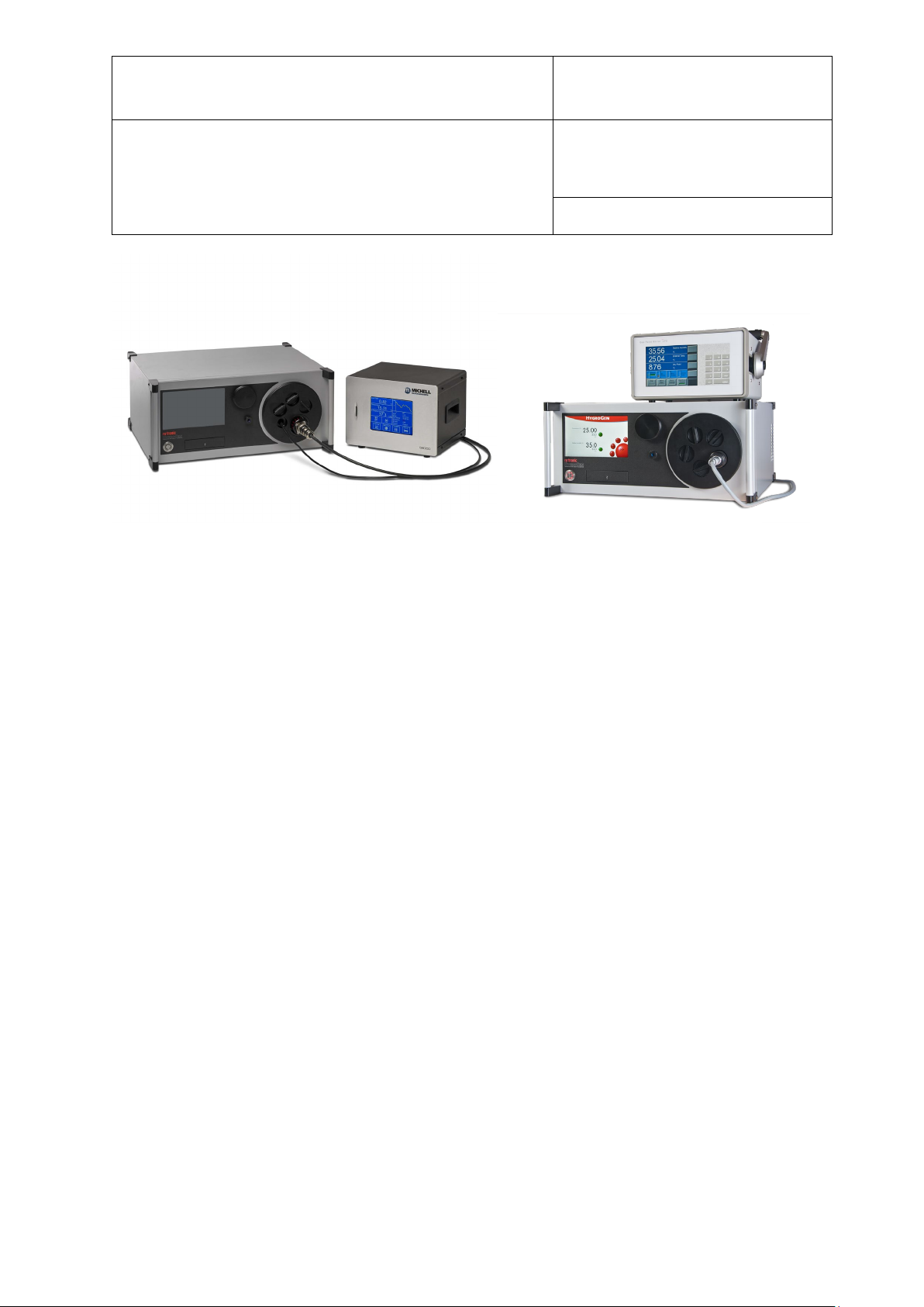
E-M-HG2-S-V3.4
Rotronic AG
Bassersdorf, Switzerland
Instruction Manual for Software
Version 3.4
Document Type
Document code Unit
HygroGen2 Humidity and Temperature Generator:
Instruction Manual
Appendix
Document title
Page 86 of 101
Figure 49: Through Door Chilled Mirror Heads
Make sure the mirror is positioned so that moving air within the chamber flows over the
mirror surface.
External sample loop operation
To use a HygroGen2 with a chilled mirror that has an external sampling head, connect via the
heated sample loop points on the back panel (Figure 2, items 1 & 2). The HygroGen2 sample
ports and internal tubing are automatically controlled to 5 °C above the chamber temperature
to eliminate the possibility of condensation formation.
The connecting lines to the mirror must also be heated if the set chamber conditions create a
dew point temperature higher than the ambient conditions. Make sure that your chilled mirror
operating capability is within the required range. For humidity values with a dew point below
ambient temperature, heated sample lines are not required.
Remove the blanking caps fitted to the sample loop Swagelok fittings and use nuts and olives
to connect the sample tubes from the chilled mirror. 6 mm OD FEP or stainless tubing should
be used to connect the sample loop out and return ports to the chilled mirror unit. If the
mirror instrument does not have a built-in pump, flow meter and regulator, we recommend
including these in the sample loop (after the mirror) to confirm the air flow rate required by
the chilled mirror instrument (typically 0.5 l/min).
© 2020; Rotronic AG E-M-HG2-S-XL-V3.4
Page 88
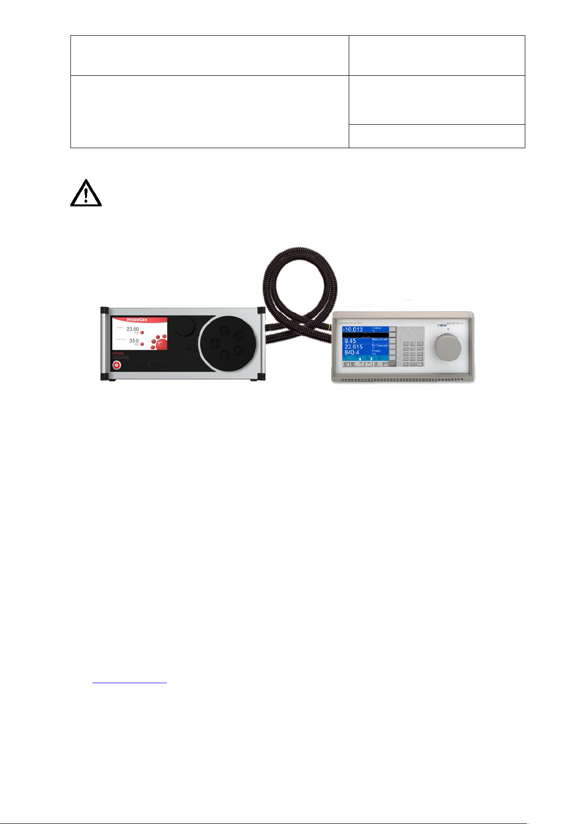
E-M-HG2-S-V3.4
Rotronic AG
Bassersdorf, Switzerland
Instruction Manual for Software
Version 3.4
Document Type
Document code Unit
HygroGen2 Humidity and Temperature Generator:
Instruction Manual
Appendix
Document title
Page 87 of 101
Caution:
When tightening or releasing the Swagelok connectors do not apply torque to
the nut/caps without using a spanner on the connector body to counteract it.
Finger tighten and then apply a quarter turn with a spanner.
Replace the blanking caps when not using the sample loop.
Figure 50: HygroGen2/Chilled Mirror with heated sample pipes
If the chilled mirror instrument is being used in conjunction with a thermometer (in order to
calculate relative humidity), the temperature probe should be positioned in the chamber. Care
should be taken to ensure that insertion depth and stem conduction effects do not induce
measurement errors.
A typical HygroGen2/Chilled Mirror set up is shown at Figure 38; note the heated sample
lines to the rear.
Set the flow rate through the sample loop according the mirror instrument manufacturer’s
specifications. A lower flow rate will improve stability criteria but may influence
measurement response time.
A2: Temperature Control
Temperature control within the HygroGen2 is performed by a fast response PT100
temperature sensor which is continuously referenced against the HC2-S control probe. The
chamber is not considered stable (as indicated by the control indicator being coloured green)
unless the reported temperature values are within the resolution of the control HC2-S. See
also Section 3.4.1.iii.
If a replacement HC2-S reference is put into the HygroGen2, and it gives a significantly
different temperature reading, it may take a while - roughly 20 minutes for every 0.1°C
discrepancy - the first-time stability control is engaged, as the self-adjustment algorithm runs.
© 2020; Rotronic AG E-M-HG2-S-XL-V3.4
Page 89
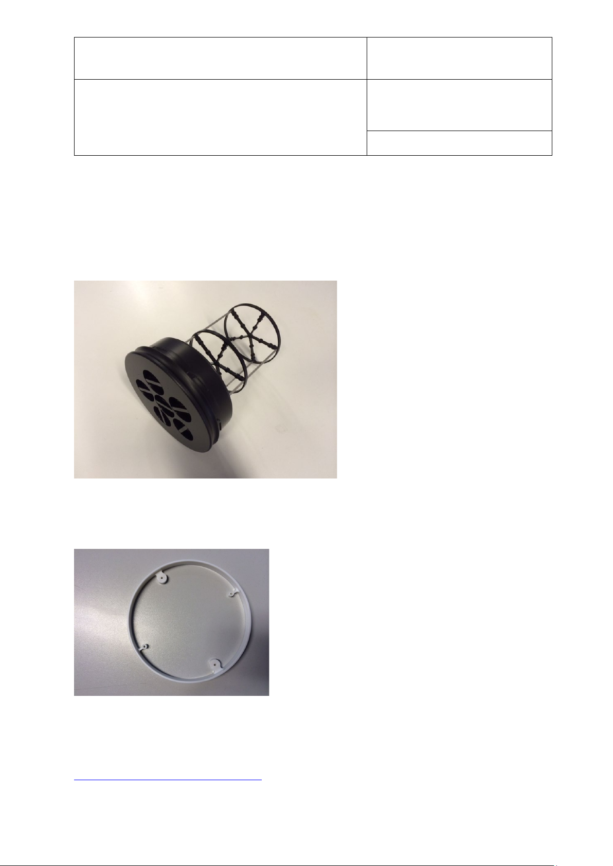
E-M-HG2-S-V3.4
Rotronic AG
Bassersdorf, Switzerland
Instruction Manual for Software
Version 3.4
Document Type
Figure 52: HG2-PRTring
Figure 51: HG2-D888888-Map
Document code Unit
HygroGen2 Humidity and Temperature Generator:
Instruction Manual
Appendix
Document title
Page 88 of 101
A3: Validation – Requirements and Accessories
For an ISO 17025 calibration system, you will need to show evidence of qualifying your own
system, and permanently logging temperature gradients within the chamber.
For this purpose, ROTRONIC has developed a special door with detachable mapping rig for
the HG2-S:
And a PRT mounting ring that can be fitted permanently into the HG2-S chamber for
continuous monitoring:
We recommend the MBW T12 multi-channel thermometer for performing these tasks, which
when used with the MBW/RHS dew point mirrors provide a calculated RH map of the entire
space.
http://www.mbw.ch/product_T12.php
© 2020; Rotronic AG E-M-HG2-S-XL-V3.4
Page 90

E-M-HG2-S-V3.4
Rotronic AG
Bassersdorf, Switzerland
Instruction Manual for Software
Version 3.4
Document Type
On Screen Message:
Fault/Action:
HC2-S NC
HC2-S not connected or faulty. Check and replace as required.
Contact service centre if message persists.
HC2-S error
Temperature or RH values are incorrect within the HygroGen2’s
to be faulty. Contact service centre if message persists.
HC null data
HC2-S communication; invalid data output. Check HC2-S and
replace. Contact service centre if message persists.
Desiccant probe NC
Desiccant probe connection failure. Service centre repair only.
in use.
Desiccant probe null
Desiccant probe communication; invalid data output. Service
work to continue.
Low Water Level
Check water level, empty and refill as required, see section 2.4.
to remain in use until next service
High Water Level
Water level is too high; empty completely and refill in
persists.
Humidification Disabled
Displays when temperature is changing. Wait for temperature to
stabilise.
Desiccant Wet
Desiccant condition warning. Replace desiccant (see section 8.2)
Heating Disabled
Over-temperature event. Heating shut down for safety reasons.
Contact service centre.
Sample Loop error
Temperature fault (sample loop temperature sensor or heater).
temperature.
Water Sensor error
Fault with level sensor. Manual supervision of water level allows
UV error
UV Lamp failure. Contact service centre.
Document code Unit
HygroGen2 Humidity and Temperature Generator:
Instruction Manual
Appendix
Document title
Page 89 of 101
B2: HygroGen2 / Screen Messages
programming. Remove Probe and check values. Replace if found
Manual control of desiccant condition enables the unit to remain
data
centre repair only. Manual control of desiccant condition enables
If message persists, manual control of water level allows the unit
accordance with section 2.4. Contact service centre if message
Operation can continue at dew points below ambient
the unit to remain in use until next service.
© 2020; Rotronic AG E-M-HG2-S-XL-V3.4
Page 91

E-M-HG2-S-V3.4
Rotronic AG
Bassersdorf, Switzerland
Instruction Manual for Software
Version 3.4
Document Type
HygroGen2 Specification
Relative Humidity
Temperature
Control
Sensor
HC2-S-S HC2A-S, capacitive RH sensor, Pt100
temperature sensor
Control type
Embedded multiple PID controller, touch screen graphical
user interface
Range
5….95 %rh
0…60 °C
(with Range Extension
option/s)
2...99 %rh
-5...60 °C
Stability at equilibrium
<0.1 %rh
<0.01 °C
Chamber temperature gradients
<0.05 °C (15-50 °C), <0.1 °C (5-60 °C), <0.15 °C (0-5 °C)
Generation method
Mixed flow with desiccant
humidifier
Peltier thermoelectric
mixing fan
Performance
Response time
3 minutes (35 to 80 %rh
change)
5 minutes (20 to 30 °C
change)
Control probe specification
±0.8 %rh (23 °C ±5)
±2 %rh (0-60 °C)
±0.1K (23 °C ±5)
±0.3K (0-60 °C)
Typical calibration uncertainty
±1.5 %rh (k=2) at 23°C
±0.15 °C (k=2) 15-50 °C
Standard Features
Water level
Low and high alarm, bar graph status indication
Water quality
UV sterilisation, auto time cycling
Desiccant condition
Condition monitored during control operation
USB ports
7 front, 2 rear
Reference connection
Temperature controlled outlet and inlet, 6mm fittings
Programmer function
20 user program memory, up to 200 set-points per program
Mechanical & Electrical
Chamber volume
2 litres, effective working volume 1.5 litres
Power
110-230 VAC 50/60Hz, 4.5A (240 VAC) 9A (110 VAC)
Enclosure
Powder coated aluminium, IP20, 450 x 406 x 205 mm
(Max)
Operating Conditions
5-40°C <2000m Altitude or less. Optimal performance
only.
Weight
13 kg
CE
Safety: EN 61010-1:2001
Document code Unit
HygroGen2 Humidity and Temperature Generator:
Instruction Manual
Appendix
Document title
Page 90 of 101
B3: HygroGen2-S Specification
dryer cell and piezoelectric
element with radial chamber
occurs within 18-28°C. Non-condensing, indoor use
© 2020; Rotronic AG E-M-HG2-S-XL-V3.4
Page 92
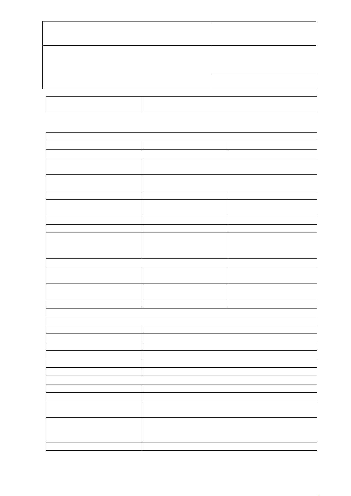
E-M-HG2-S-V3.4
Rotronic AG
Bassersdorf, Switzerland
Instruction Manual for Software
Version 3.4
Document Type
EMC: EN 61326-1:2006 EN 61326-1:2006 & EN 61000-61:2007
HygroGen2 Specification
Relative Humidity
Temperature
Control
Sensor
HC2-S-S HC2A-S, capacitive RH sensor, Pt100
temperature sensor
Control type
Embedded multiple PID controller, touch screen graphical
user interface
Range
5….95 %rh
0…60 °C
(with Range Extension
option/s)
2...99 %rh
-5...60 °C
Stability at equilibrium
<0.1 %rh
<0.01 °C
Chamber temperature gradients
<0.05 °C (15-50 °C), <0.1 °C (5-60 °C), <0.15 °C (0-5 °C)
Generation method
Mixed flow with desiccant
humidifier
Peltier thermoelectric
mixing fan
Performance
Response time
15 minutes (35 to 80 %rh
change)
15 minutes (20 to 30 °C
change)
Control probe specification
±0.8 %rh (23 °C ±5)
±2 %rh (0-60 °C)
±0.1K (23 °C ±5)
±0.3K (0-60 °C)
Typical calibration uncertainty
±1.5 %rh (k=2) at 23 °C
±0.15 °C (k=2) 15-50 °C
Standard Features
Water level
Low and high alarm, bar graph status indication
Water quality
UV sterilisation, auto time cycling
Desiccant condition
Condition monitored during control operation
USB ports
7 front, 2 rear
Reference connection
Temperature controlled outlet and inlet, 6mm fittings
Programmer function
20 user program memory, up to 200 set-points per program
Mechanical & Electrical
Chamber volume
20 litres, effective working volume 15 litres
Power
110-230 VAC 50/60Hz, 4.5A (240 VAC) 9A (110 VAC)
Enclosure
Powder coated aluminium, and steel, IP20, 80x62x41cm
(Max)
Operating Conditions
5-40°C <2000m Altitude or less. Optimal performance
only.
Weight
37 kg
Document code Unit
HygroGen2 Humidity and Temperature Generator:
Instruction Manual
Appendix
Document title
Page 91 of 101
B4: HygroGen2-XL Specification
dryer cell and piezoelectric
element with radial chamber
occurs within 18-28°C. Non-condensing, indoor use
© 2020; Rotronic AG E-M-HG2-S-XL-V3.4
Page 93
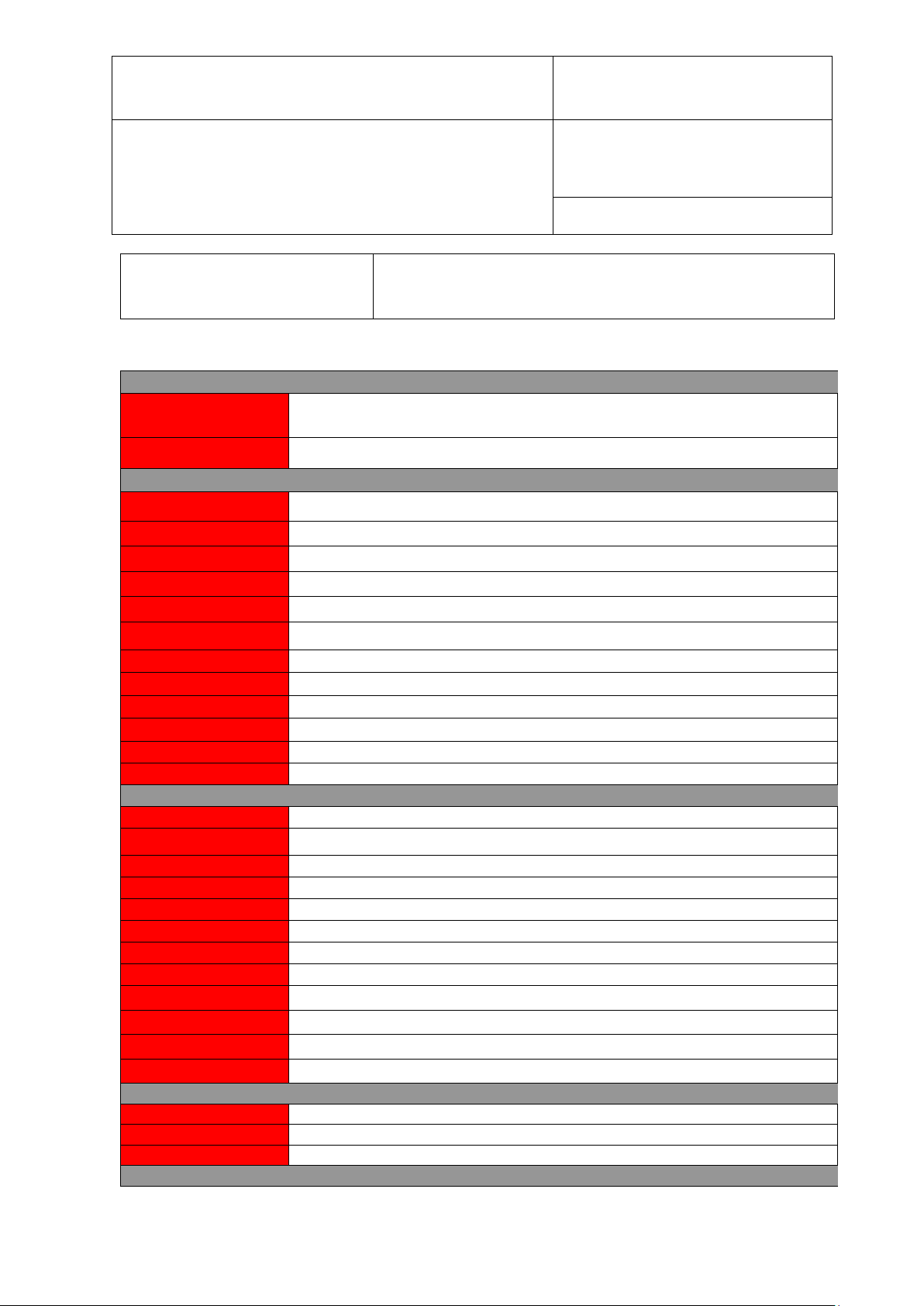
E-M-HG2-S-V3.4
Rotronic AG
Bassersdorf, Switzerland
Instruction Manual for Software
Version 3.4
Document Type
CE
Safety: EN 61010-1:2001
1:2007
HygroGen2 with touch screen, calibrated control/reference probe, set-point control & programmer
Order chamber door separately
HygroGen2-XL with touch screen, calibrated control/reference probe, set-point control & programmer
function, heated sample loop, 2 x desiccant cell, fill syringe, embedded HW4-P.
HG2 door 5 x 15 mm ports (for 5 HC2-Ss) with 5 bungs, order specific B1 sleeves for smaller probe
diameters
MBW/RHS External Reference - extension to enable MBW chilled mirror as external reference. NB Requires
AutoCal or RemoteAPI, activation code
HC2-S-S
Standard control or reference probe. Order UKAS temperature and RH calibration separately
Document code Unit
HygroGen2 Humidity and Temperature Generator:
Instruction Manual
Appendix
Document title
Page 92 of 101
EMC: EN 61326-1:2006 EN 61326-1:2006 & EN 61000-6-
B5: HygroGen2 Order Codes:
HYGROGEN2
HG2-S
HG2-XL
Chamber doors / probe sleeves / bungs
HG2-D-11111
HG2-D-888888 HG2 door 6 x 30 mm ports with 6 bungs, order specific B8 sleeves to suit smaller probe diameters
HG2-D-HFW HygroGen probe door for HF3 and HF4 wall mount transmitters, also HP21 hand-held with fixed probe
HG2-DP-00000 HG2 clear acrylic door (no ports) for instruments with displays
HG2-B1 15 mm Bung for HG2-D-11111
HG2-B1-xx B1 probe sleeves for HG2-D-11111 (15 mm external, internal probe diameter see xx diameter codes)
HG2-B8 30 mm Bung for HG2-D-888888
HG2-B8-xx B8 probe sleeves for HG2-D-888888 (30 mm external, internal probe diameter see xx diameter codes)
HG2-D-xxxxx HG2 fully custom door for > 30 mm ports, see xx diameter codes
HG2-Bxx Custom bung
HG2-Bxx-xx Custom probe adaptor sleeves (all types)
HG2-D-888888-Map HG2-D888888 door with detachable mapping rig
Optional Enhanced Features
HG2-AutoCal-Code
HG2-ExtRef-Code
HG2-RemoteSS-Code
HG2-TempExt-Code
HG2-HumiExt-Code
HG2-RemoteAPI-Code
HG2-EF-Bundle1
HG2-EF-Bundle2
HG2-EF-Bundle3
HG2-EF-Bundle4
HG2-EF-Bundle5
HG2-EF-Bundle6
Spares
HG2-DC Additional desiccant cell, pre-filled with molecular sieve
HG2-FILL Fill tube and syringe
function, heated sample loop, desiccant cell, fill syringe, embedded HW4-P.
AutoCal function, activation code
LAN Remote Control (Screen Share) – remote control access via VNC, activation code
Low Temperature Range Extension -5…60 °C, activation code
Humidity Range Extension 2…99 %rh, activation code
LAN Remote Control (API) – remote control application programming interface, activation code
Enhanced Feature Bundle 1 [Temp/Humi/AutoCal], activation code
Enhanced Feature Bundle 2 [AutoCal/Ext Ref/RemoteSS], activation code
Enhanced Feature Bundle 3 [Temp/Humi/AutoCal/Ext Ref/RemoteSS], activation code
Enhanced Feature Bundle 4 [RemoteAPI/Ext Ref/RemoteSS], activation code
Enhanced Feature Bundle 5 [Temp/Humi/RemoteAPI/Ext Ref/RemoteSS], activation code
Enhanced Feature Bundle 6 [Temp/Humi/AutoCal/RemoteAPI/Ext Ref/RemoteSS], activation code
Accessories
© 2020; Rotronic AG E-M-HG2-S-XL-V3.4
Page 94
E-M-HG2-S-V3.4
Rotronic AG
Bassersdorf, Switzerland
Instruction Manual for Software
Version 3.4
Document Type
HG2-MON
HG2-PRT-ring
HG2-DES-3
xx Diameter codes for customised diameters
0
No probe ports
1
15 mm (HC2-S)
2
20 mm
3
25 mm
4
10 mm
5
5 mm
6
12 mm
7
18 mm
8
30 mm
9
Cable gland to accept 9…17 mm diameter probes
A
6 mm
B
4 mm
C
22 mm
D
23 mm
E
13 mm
F
19 mm
G
21mm
H
18.5 mm (Vaisala HMP45AD)
I
18.2 mm (Aanderaa 3445)
J
9 mm
K
19.75 mm (no 'O' rings)
L
Cable gland to accept 3 - 7 mm diameter probes
M
12.7 mm
N
6.35 mm (1/4 inch)
O
not used
P
3 mm
Q
not used
R
13.5 mm
S
26 mm
T
34 mm
U
14 mm
V
20 mm cable gland 5 -12 mm probes
W
32 mm cable gland 11-21mm probes
Document code Unit
HygroGen2 Humidity and Temperature Generator:
Instruction Manual
Appendix
Document title
Page 93 of 101
HG2-TB HygroGen2-S transit bag, lightweight
HG2-TC HygroGen2-S heavy-duty transit case
DVI monitor and lead
HG2-DVIC DVI lead
HG2-AC3001-L/050 HC2-S calibration cable, 50 cm, USB
HG2-AC3001-L/050 (5) HC2-S calibration cable, 50 cm, USB. Bundle of 5 pieces HG2-AC3001-L/050
PRT mounting ring for permanent monitoring of HG2-S using external temperature reference
Service & Consumables
HG2-S-SERVICE HygroGen2 service, recommended at 12-month intervals. Warranty period then extended by 12 months
HG2-LABOUR On-site service and training, per day, excludes 40p per mile and expenses incurred at cost
Molecular sieve desiccant (3 kg)
© 2020; Rotronic AG E-M-HG2-S-XL-V3.4
Page 95

E-M-HG2-S-V3.4
Rotronic AG
Bassersdorf, Switzerland
Instruction Manual for Software
Version 3.4
Document Type
X
not used
Y
15 mm angled Vaisala HMDW40/W50
Z
not used
xx Diameter codes for customised diameters (continued)
A1
24 mm
A2
12.5 mm
A3
24.7mm
A4
32 mm
A5
16 mm
A6
26.5 mm
A7
36 mm
A8
Cable gland to accept 22…32 mm diameter probes
A9
42 mm
C1
50 mm Optidew
C2
Cable gland to accept 32…38mm diameter probes
C3
General Eastern Chilled Mirror head (32 mm thread)
C4
47 mm
C5
Michell Optidew Chilled Mirror head (threaded)
C6
80 mm
C7
8 mm
C8
M24 x 1
C9
M20 x 1.5
Document code Unit
HygroGen2 Humidity and Temperature Generator:
Instruction Manual
Appendix
Document title
Page 94 of 101
© 2020; Rotronic AG E-M-HG2-S-XL-V3.4
Page 96
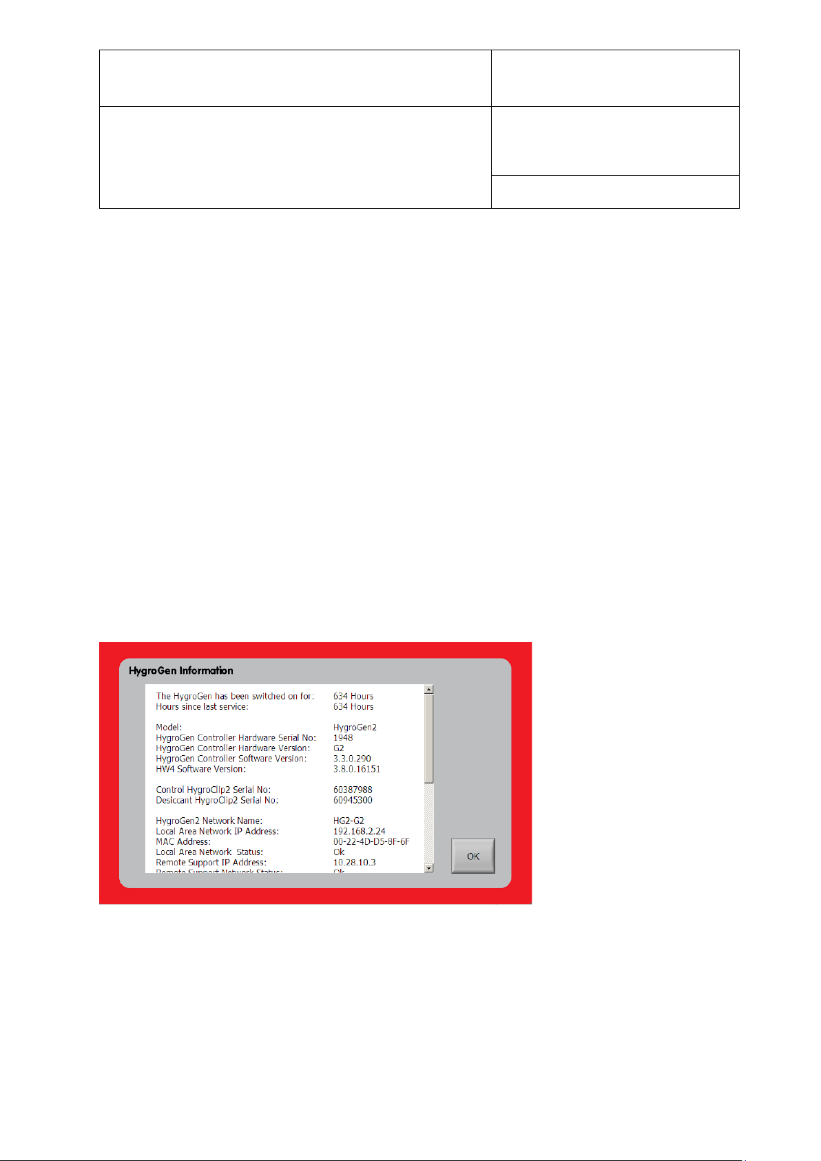
E-M-HG2-S-V3.4
Rotronic AG
Bassersdorf, Switzerland
Instruction Manual for Software
Version 3.4
Document Type
Document code Unit
HygroGen2 Humidity and Temperature Generator:
Instruction Manual
Appendix
Document title
Page 95 of 101
C1: HygroGen2 Warranty Statement
ROTRONIC will grant a warranty for the HygroGen2 for a period of 12 months from the date
of delivery in respect of any evidenced faulty workmanship and materials. The warranty
period is extended by a further 12 months when the unit is serviced at a ROTRONIC
approved service centre 12 months after the date of supply. Should the instrument be proven
not to meet the published specifications or to be contrary to contract upon inspection, the
customer shall grant ROTRONIC the opportunity hereunder of repairing the fault by
returning the unit carriage paid to ROTRONIC.
Should the supply or delivery of any improvement or replacement not prove possible, the
customer may choose between having the purchase price reduced or demanding the contract
of sale to be rescinded (conversion). Damage resulting from natural wear and tear, an act of
God or non-compliance with the operating instructions shall be excluded from the warranty
as well as mechanical interference by the customer or by third parties with plant and
equipment of ROTRONIC without its written permission. No liability will be accepted for
defects, damage or injury caused due to installation not carried out in accordance with the
manufacturer’s installation instructions.
The instrument maintains a record of its usage and this may only be reset by an authorised
service centre; this will determine the warranty period granted.
Figure 53: HygroGen Information
© 2020; Rotronic AG E-M-HG2-S-XL-V3.4
Page 97

E-M-HG2-S-V3.4
Rotronic AG
Bassersdorf, Switzerland
Instruction Manual for Software
Version 3.4
Document Type
Document code Unit
HygroGen2 Humidity and Temperature Generator:
Instruction Manual
Appendix
Document title
Page 96 of 101
C2: Our Global Locations
Manufacturer/Service Center:
Rotronic Instruments (UK) Ltd
Crompton Fields
Crompton Way
Crawley RH10 9EE
United Kingdom
Phone: +44(0)1293 571000
Service Centers:
www.processSensing.com/en-us/contact/global-locations/
© 2020; Rotronic AG E-M-HG2-S-XL-V3.4
Page 98

Input values:
23
°C
80
% RH
Temperature sensitivity
4.96
% RH/deg C
Reference
Uncertainty source
Distribution
Value
Units
Sensitivity
Equiv
RH
Divisor
One
SD
Squares
1
Uncertainty of reference probe
normal
0.900000
%rh
1.000000
0.900000
2.00
0.450
0.203
2
Repeatability of humidity
normal
0.100000
%rh
1.000000
0.100000
1.00
0.100
0.010
3
Reference drift
rectangular
1.000000
%rh
1.000000
1.000000
1.73
0.577
0.333
4
Reference resolution
rectangular
0.050000
%rh
1.000000
0.050000
1.73
0.029
0.001
5
Chamber temperature gradients
rectangular
0.020000
°C
4.960000
0.099200
1.73
0.057
0.003
6
Temperature stabilisation
rectangular
0.005000
°C
4.960000
0.024800
1.73
0.014
0.000
7
Repeatability of temperature
normal
0.050000
°C
4.960000
0.248000
1.00
0.248
0.062
8
Humidity stabilisation
rectangular
0.050000
%rh
1.000000
0.050000
1.73
0.029
0.001
9
Humidity fluctuations
rectangular
0.050000
%
RH
1.000000
0.050000
1.73
0.029
0.001
10
Instrument Under Test (IUT) Resolution
rectangular
0.050000
%
RH
1.000000
0.050000
1.00
0.050
0.003
11
Standard deviation of Ref readings
normal
0.050000
%rh
1.000000
0.050000
1.00
0.050
0.003
12
Standard deviation of IUT readings
normal
0.100000
%rh
1.000000
0.100000
1.00
0.100
0.010
Reference
Sum of squares
0.63
1
From calibration certificate - check uncertainty at input values
sum of
squares)
0.793
2
From Standard Deviation of 10 repeated calibration runs
Expanded uncertainty (95 %
confidence)
1.59
3
Drift between two successive calibrations of the reference
instrument
4
Resolution from manufacturer’s specification
5
Measured temperature gradients from the ROTRONIC
HygroGen2 Service
6
Measured stability from the ROTRONIC HygroGen2 Service
7
From Standard Deviation of 10 repeated calibration runs
8
Resolution of ROTRONIC HygroGen2 Control Clip
9
Resolution of ROTRONIC HygroGen2 Control Clip
10
Resolution from manufacturer’s specification
11
Standard Deviation of Ref readings during calibration
D1: HygroGen2 Uncertainty Framework - Internal RH Probe
Standard uncertainty (√
Page 99

D
2: HygroGen2 Uncertainty Framework - External RH Probe
Input values:
23
°C
80
% RH
Temperature sensitivity
4.96
% RH/deg C
Reference
Uncertainty source
Distribution
Value
Units
Sensitivity
Equiv RH
Divisor
One SD
Squares
1
Uncertainty of reference probe
normal
0.900000
%rh
1.000000
0.900000
2.00
0.450
0.203
2
Repeatability of humidity
normal
0.100000
%rh
1.000000
0.100000
1.00
0.100
0.010
3
Reference drift
rectangular
1.000000
%rh
1.000000
1.000000
1.73
0.577
0.333
4
Reference resolution
rectangular
0.050000
%rh
1.000000
0.050000
1.73
0.029
0.001
5
Chamber temperature gradients
rectangular
0.020000
°C
4.960000
0.099200
1.73
0.057
0.003
6
Gradients through probe stem
rectangular
0.100000
°C
4.960000
0.496000
1.73
0.286
0.082
7
Temperature stabilisation
rectangular
0.005000
°C
4.960000
0.024800
1.73
0.014
0.000
8
Repeatability of temperature
normal
0.050000
°C
4.960000
0.248000
1.00
0.248
0.062
9
Humidity stabilisation
rectangular
0.050000
%rh
1.000000
0.050000
1.73
0.029
0.001
10
Humidity fluctuations
rectangular
0.050000
%rh
1.000000
0.050000
1.73
0.029
0.001
11
Instrument Under Test (IUT) Resolution
rectangular
0.050000
%rh
1.000000
0.050000
1.00
0.050
0.003
12
Standard deviation of Ref readings
normal
0.050000
%rh
1.000000
0.050000
1.00
0.050
0.003
13
Standard deviation of IUT readings
normal
0.100000
%rh
1.000000
0.100000
1.00
0.100
0.010
Reference
Sum of squares
0.71
1
From calibration certificate - check uncertainty at input values
Standard uncertainty (√sum of squares)
0.843
2
From Standard Deviation of 10 repeated calibration runs
Expanded uncertainty (95 % confidence)
1.69
3
Drift between two successive calibrations of the reference instrument
4
Resolution from manufacturer‘s specification
5
Measured temperature gradients from the ROTRONIC HygroGen2 Service
6
Stem conduction
7
Measured stability from the ROTRONIC HygroGen2 Service
8
From Standard Deviation of 10 repeated calibration runs
9
Resolution of ROTRONIC HygroGen2 Control Clip
10
Resolution of ROTRONIC HygroGen2 Control Clip
11
Resolution from manufacturer‘s specification
12
Standard Deviation of Ref readings during calibration
13
Standard Deviation of IUT readings during calibration
12
Standard Deviation of IUT readings during calibration
Page 100

D3: HygroGen2 Uncertainty Framework - Chilled Mirror Reference
23
°C
50
% RH
Temperature sensitivity
3.1
% RH/deg C
Reference
Uncertainty source
Distribution
Value
Units
Sensitivity
Equiv
RH
Divisor
One
SD
Squares
1 Uncertainty of chilled mirror reference
normal
0.200000
°C
3.100000
0.620000
2.00
0.310
0.096
2
Repeatability of humidity
normal
0.100000
%rh
1.000000
0.100000
1.00
0.100
0.010
3
Chamber temperature gradients
rectangular
0.020000
°C
3.100000
0.062000
1.73
0.036
0.001
4
Temperature stabilisation
rectangular
0.005000
°C
3.100000
0.015500
1.73
0.009
0.000
5
Repeatability of temperature
normal
0.050000
°C
3.100000
0.155000
1.00
0.155
0.024
6
Humidity stabilisation
rectangular
0.050000
%rh
1.000000
0.050000
1.73
0.029
0.001
7
Humidity fluctuations
rectangular
0.050000
%rh
1.000000
0.050000
1.73
0.029
0.001
8
Instrument under test (IUT) resolution
rectangular
0.050000
%rh
1.000000
0.050000
1.00
0.050
0.003
9
Standard deviation of Ref readings
normal
0.050000
%rh
1.000000
0.050000
1.00
0.050
0.003
10
Standard deviation of IUT readings
normal
0.100000
%rh
1.000000
0.100000
1.00
0.100
0.010
Reference
Sum of squares
0.15
1
See sheet Dew Point UA
Standard uncertainty (√sum of squares)
0.385
2
From Standard Deviation of 10 repeated calibration runs
Expanded uncertainty (95% confidence)
0.77
3
Measured temperature gradients from the ROTRONIC HygroGen2 Service
4 Measured stability from the ROTRONIC HygroGen2 Service
5
From Standard Deviation of 10 repeated calibration runs
6
Resolution of ROTRONIC HygroGen2 Control Clip
7
Resolution of ROTRONIC HygroGen2 Control Clip
8
Resolution from manufacturer’s specification
9
Standard Deviation of Ref readings during calibration
10
Standard Deviation of IUT readings during calibration
 Loading...