

Page 1
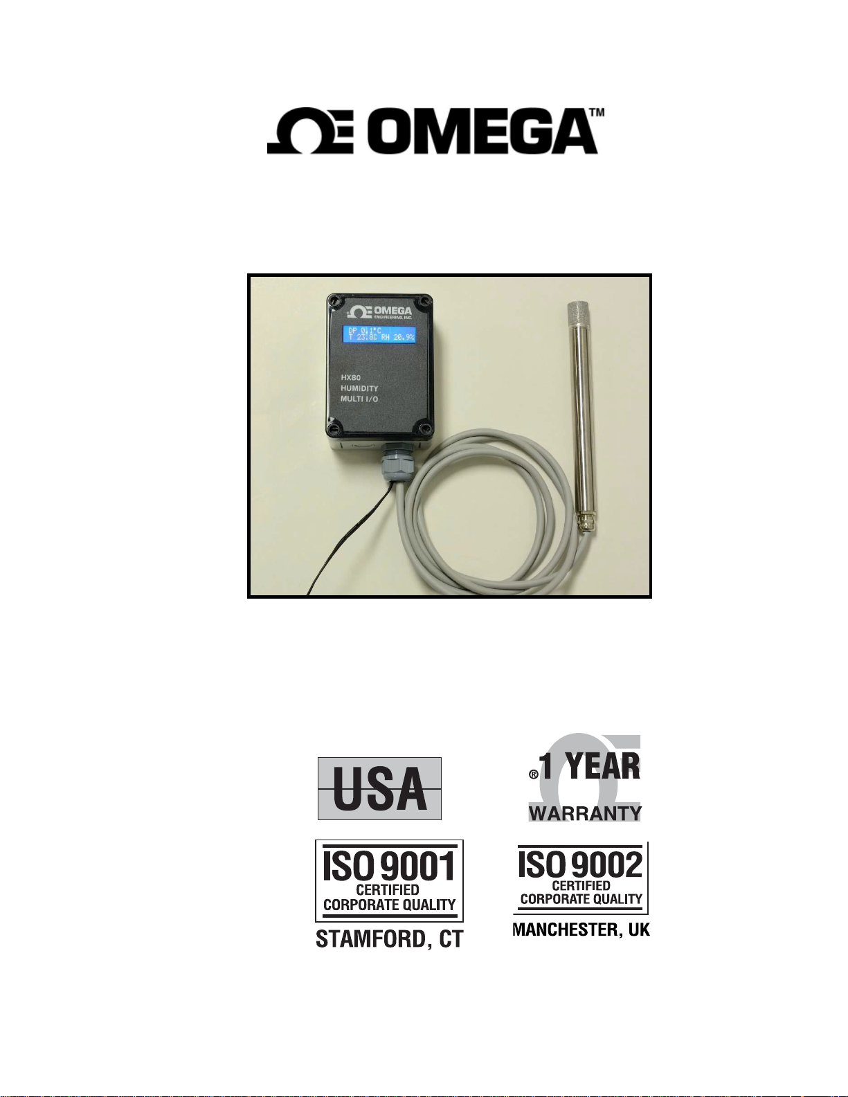
HX80A SERIES
OPERATORS MANUAL
MADE IN
Rev F February 2021
Page 2
O
[
For immediate technical or application assistance:
U.S.A.
Mexico:
Czech Republic:
Germany/Austria:
and
Canada:
United Kingdom:
ISO 9002 Certified
Sales Se
Customer Service: 1-800-622-2378/1-800-622-BEST •
Engineering Service: 1-800-872-9436/1-800-USA-WHEN •
En Espanol: (001) 203-359-7803
e-mail: espanol@omega.com
FAX: (001) 203-359-7807
info@omega.com.mx
Frystatska 184, 733 01 Karvina, Czech Republic
TEL: +420 (0)59 6311899
FAX: +420 (0)59 6311114
Toll Free: 0800-1-66342
e-mail: info@omegashop.cz
Daimlerstrasse 26, D-75392 Deckenpfronn, Germany
TEL: +49 (0)7056 9398-0
FAX: +49 (0)7056 9398-29
Toll Free in Germany: 0800 639 7678
e-mail: info@omega.de
One Omega Drive, River Bend Technology Centre
Northbank, lrlam, Manchester
M44 5BD United Kingdom
TEL: +44 (0)161 777 6611
FAX:
Toll Free in United Kingdom: 0800-488-488
e-mail: sales@omega.co.uk
rvice: 1-800-826-6342/1-800-TC-OMEGA•
Servicing Europe:
+44
(0)161 777 6622
It is the policy of OMEGA Engineerin,gInc. to comply with all worldwide safety and EMC/EMI regulations that
apply. OMEGA is constantly pursuing certification of its products to the European New Approach Directives.
OMEGA
The informatoon con ta i ned in th is docum e nt 1s bel ieved to
contains, and reserves the right to alter specifications without notice.
WARNING: These products are not designed for use in, and should not
will add the CE mark
to
every appropriate device upon
be
corr ect, but OMEGA accepts no liability for any errors it
ce
rtifci
ation.
be
used for, human applications.
Page 3
1
QUICK STARTUP GUIDE – Page 1
ITEM
RIBBON CABLE WIRE #
Power Supply – Pos. 7
Power Supply – Neg.
1 (blue tracer)
Output 1 – Pos. 2
Output 2 – Pos. 6
Output 3 – Pos. 8
Output Common 4
Serial Output – TX 5
Serial Output – RX 3
TARTUP
S
WHEN USING PROBE ONLY:
1.
Mount the Probe in position to measure the desired gas.
2.
Connect Probe wiring by cutting off connector or using a mating
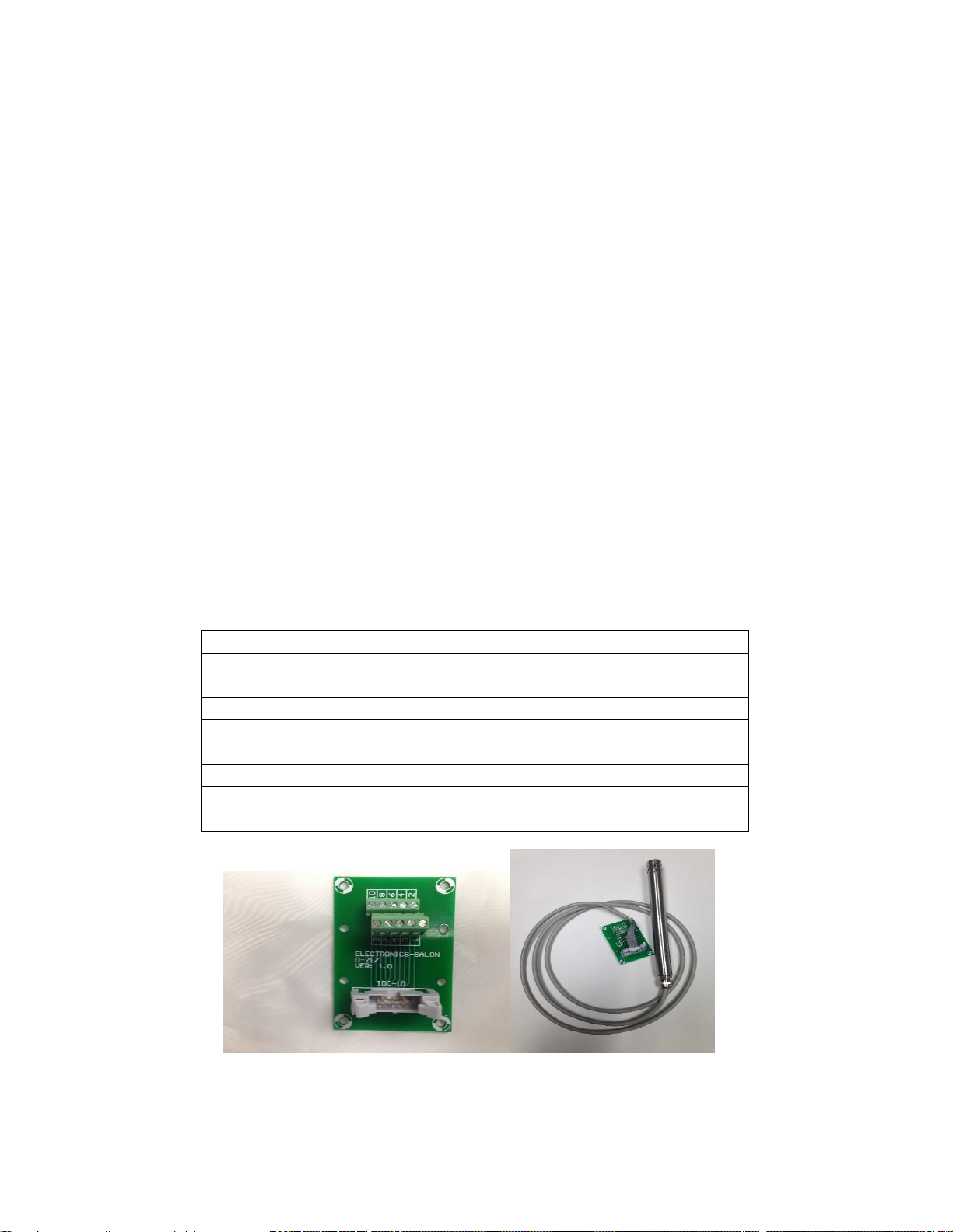
connector (HX85A-COB), as shown below:
HX80A SERIES
HX85A-COB (for HX85A probe series only)
Page 4

2
Notes: Connect only the Outputs desired. See drawing in the HX80A Manual for
further connection details.
Do not apply DC Power until all wiring is completed.
Page 5
3
HX80A SERIES
ITEM
CONN.
TERM.
Power Supply (+)
J8 2
Power Supply (-)
J8 1
Analog Out 1 (+)
J9 1
Analog Out 1 (-)
J9 2
Analog Out 2 (+)
J9 3
Analog Out 2 (-)
J9 4
Analog Out 3 (+)
J9 5
Analog Out 3 (-)
J9 6
Alarm Relay 1
J2 1
Alarm Relay 1
J2 2
Alarm Relay 2
J2 3
Alarm Relay 2
J2 4
RS-232 TX
J6 2
RS-232 RX
J6 3
RS-232 RTN
J6 5
QUICK STARTUP GUIDE – Page 2
WHEN USING PROBE WITH ELECTRONICS UNIT:
1.
Mount the Probe and Electronics Unit.
2.
Connect cable from Probe to Electronics Unit
(if applicable).
3.
Connect Power Supply to Electronics Unit.
4.
Connect Analog Outputs of Electronics Unit.
5.
Connect Digital Output of Electronics Unit.
6.
Connect Alarm Relays of Electronics Unit.
7.
Connect RS-232 Serial Port of Electronics Unit.
Notes:
Connect only the Outputs desired.
Page 6

4
TABLE OF CONTENTS
Page
1.0 Quick Startup
2.0 Introduction
2.1 General Description
2.2 Specifications Summary
2.3 Model Descriptions
2.4 Available Options
3.3.1 Probe Only
3.3.2 Probe with Electronics
4.0 Basic Block Diagram
4.1 Probe Assembly
4.2 Electronics Module
4.3 Complete System
5.0 Operation
5.1 Initial Bench Testing
5.2 Normal Operation
5.3 Factory Default Conditions
5.4 RS-232 Serial Port
1
List of Illustrations
List of Tables
3.1 Installation
3.2 Mounting the Probe
3.2 Mounting the Electronics Unit
3.3 Electrical Wiring
4
4
6
6
7
8
9
11
11
12
12
12
15
18
18
18
20
21
21
21
21
23
5.4.1
Serial Port Setup 23
5.4.2
Changing the Digital Display 23
5.4.3
Changing the Output Ranges 24
5.4.4
Programming the Alarm Relays 25
5.4.5
Calibrating the Analog Outputs 26
6.1
Maintenance 27
6.2
Sensor Circuit Board 27
6.1.1 Replacing the Sensor Board 27
6.1.3 Sensor Reassembly 27
7.0 Specifications 28
Page 7

5
LIST OF ILLUSTRATIONS Page
2-1 HX80 Configurations 6
3-1
System with Sample Cell 11
3-2
Installing the Mounting Lugs
3-3
Probe Wiring, Ribbon Cable
3-3a Probe Wiring 15
3-4 Electronics Unit Wiring
4-1
Probe Block Diagram 18
4-2
System Block Diagram 20
6-2 Sensor Exploded View 27
12
14
17
LIST OF TABLES Page
2-1
Standard Configurations 8
2-2
Measurement Ranges 10
3-1 Probe Wiring, Ribbon Cable 13
3-11a Probe Wiring 14
3-2
Electronics Wiring 16
3-3
Serial Port Wiring 16
5-1 Standard Output Scaling 22
Page 8
6
2.1
INTRODUCTION
2.2
GENERAL DESCRIPTION
The HX80A Series is a family of humidity probes and electronic modules that offer a
variety of measurement parameters with high accuracy. In addition to Percent Relative
Humidity (%RH), probes are available to also measure Temperature and Pressure.
Electrical analog and digital outputs are provided for not only these measured
parameters but may be provided for microprocessor- computed parameters as well.
These include parts-per-million by volume (ppmv), parts-per-million by weight (ppmw),
grains of water per pound of dry gas (gr/lb), and others.
The HX80A system is designed for ease of installation and operation. Field-replaceable
sensor modules have standardized outputs for interchangeability without recalibration.
The power requirement is a common unregulated DC power supply. User-available
electrical outputs include linear analog voltage (or optional current), a digital bidirectional serial port, and alarm relays. Mounting options include Wall Mount, Remote
Mount, and Duct Mount configurations. Additional options include high temperature and
high-pressure probes. A remote or local Display Unit (Type DIS) is available, with a
two-line LCD display, alarm relays, and three 4 to 20 mA electrical outputs.
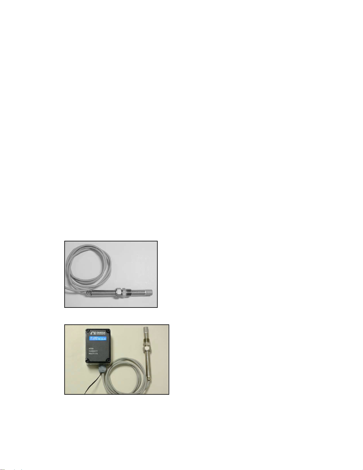
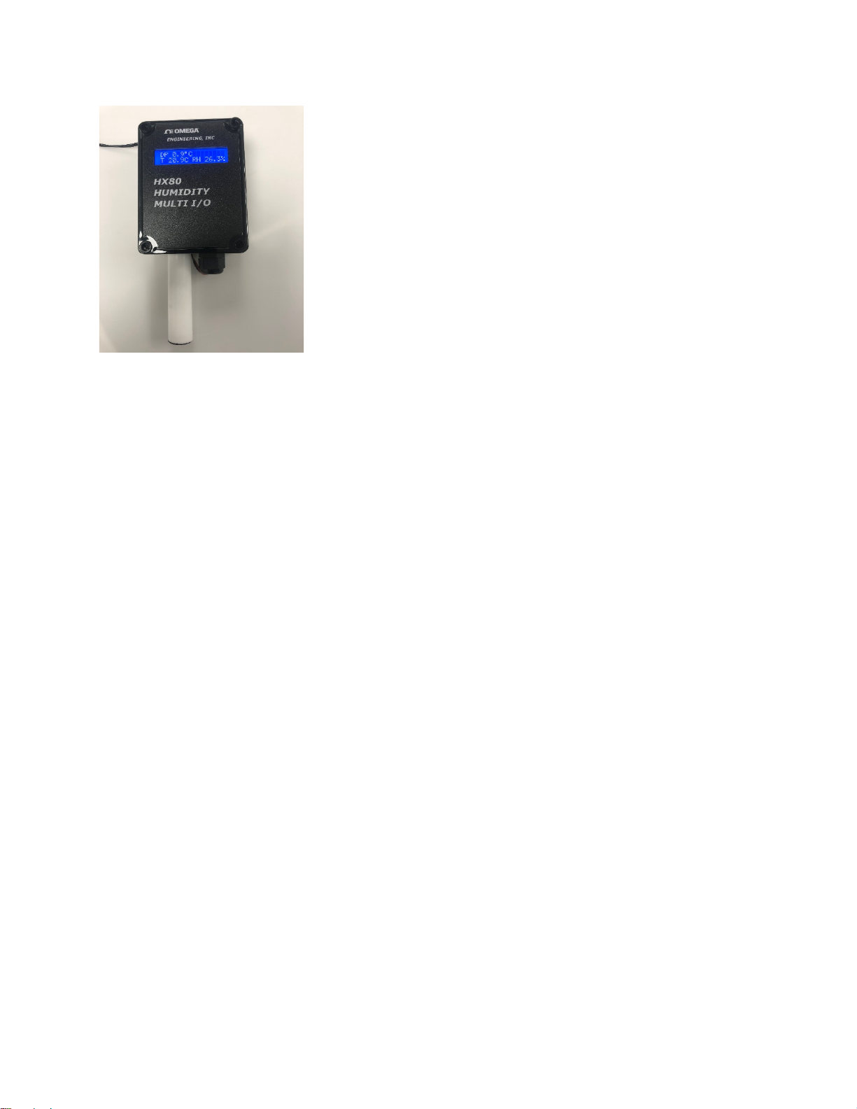
Figure 2-1 Some of the Available HX80A Configurations
a. Stand-alone Probe
b. Remote Mount with Display Option
Page 9
7
c. Wall Mount Unit
2.2.1
Analog Outputs: 0 – 10 Vdc (X3)
Digital Output: RS-232C
Power Supply: 18 to 30 Vdc, unregulated, 50 mA max.
RH Accuracy: +/- 1% nominal
Temp. Accuracy: +/- 0.5°C
Mounting: Cable Length: 6 feet
Fitting: ¾ inch stainless steel
Dimensions: Length: 8 inches
Materials: Housing: Stainless Steel
STAND-ALONE PROBE
NPT thermocouple fitting
Diameter: ¾ inch
Filter: Sintered Stainless Steel (removable)
2.2.2
Analog Outputs: 4 to 20 mA (X3)
Digital Output: RS-232C, bi-directional
Alarm Relays: Form A (SPST, NO) X2
Power Supply: 18 to 30 Vdc unregulated, 50 mA max.
PROBE WITH ELECTRONICS UNIT (remote, wall, duct)
Page 10
8
RH Accuracy: +/- 1% nominal
HX85A
x
HX85BA
x
HX85PA
x HX86A
X
HX86BA
X
HX86PA
X
HX86A-W
X
HX86BA-W
X
HX86A-D
X
HX86BA-D
X
Temp. Accuracy: +/- 0.5°C
Display: 2 line LCD
Electronics Housing Protection:
IP66 (NEMA 4X) Dust tight and moisture resistant
Table 2-1 HX80A, Standard Available Configurations
Probe (only) Probe with electronics unit
2.3
HX80A SERIES MODEL DESCRIPTIONS
HX85A – A Humidity/Temperature probe providing RH, Dew Point, and Temperature
outputs with an operating temperature up to 120C.
HX85BA – A Humidity/Temperature/Barometric Pressure probe providing RH,
Temperature, and Pressure outputs with an operating temperature up to 120C.
HX85PA – A Humidity/Temperature/High Pressure probe providing RH, Temperature,
and Pressure outputs with an operating temperature up to 120C.
HX86A – A Humidity/ High Temperature probe providing RH, Temperature, and Dew
Point outputs, with remote Electronics Unit including Digital Display with an operating
temperature up to 120C.
HX86BA – A Humidity/High Temperature/Barometric Pressure probe providing RH,
Temperature, and Pressure outputs, with remote Electronics Unit including Digital
Display with an operating temperature up to 120C.
HX86PA – A Humidity/High Temperature/High Pressure probe providing RH,
Temperature, and Pressure outputs, with remote Electronics Unit including Digital
Display with an operating temperature up to 120C.
Page 11

9
HX86A-W – A wall mount Humidity/ High Temperature probe providing RH,
Temperature, and Dew Point outputs, with Electronics. Unit includes Digital Display
with an operating temperature up to 60C.
HX86BA-W – A wall mount Humidity/High Temperature/Barometric Pressure probe
providing RH, Temperature, and Pressure outputs, with Electronics Unit including
Digital Display with an operating temperature up to 60C.
HX86A-D – A duct mount Humidity/ High Temperature probe providing RH,
Temperature, and Dew Point outputs, with remote Electronics Unit including Digital
Display with an operating temperature up to 120C.
HX86BA-D – A duct mount Humidity/High Temperature/Barometric Pressure probe
providing RH, Temperature, and Pressure outputs, with remote Electronics Unit
including Digital Display with an operating temperature up to 120C.
Wall Mount Configuration
2.4
AVAILABLE OPTIONS
HX86A-DIS – Remote electronics module with two-line LCD digital display, three 4 to 20
mA analog outputs, RS-232C, and two programmable alarm relays. This unit can be
added to existing Probes (HX85A series in the field).
HX80- SENSOR – Field-replaceable sensor module for RH/Temperature.
Interchangeability accurate to published specification.
HXP80-SENSOR – Field-replaceable sensor module for RH/Temperature/Pressure.
Interchangeability accurate to published specification.
HXB80-SENSOR – Field-replaceable sensor module for RH/Temperature/Barometric
Pressure. Interchangeability accurate to published specification.
HX80-CHAMBER – Sample chamber with inlet and outlet fittings.
HX85A-COB - An adapter board for HX85 series only. It is used as a connecting
board for easy wiring.
Page 12

10
Table 2-2 HX80A Series Sensor Actual Measurement Ranges.
MODEL NO.
OUTPUT 1
OUTPUT 2
OUTPUT 3
HX85A
PERCENT RH
AIR TEMP.
DEW POINT
MEASUREMENT RANGE
5 TO 95%
-20 to +120ºC
-60 to +40ºC
HX85BA
PERCENT RH
AIR TEMP.
BAR. PRESSURE
MEASUREMENT RANGE
5 TO 95%
-20 to +120ºC
10 to 1100 MB
HX85PA
PERCENT RH
AIR TEMP.
ABS. PRESSURE
MEASUREMENT RANGE
5 TO 95%
-20 to +120ºC
0 to 200 psia
HX86A
PERCENT RH
AIR TEMP.
DEW POINT
MEASUREMENT RANGE
5 TO 95%
-20 to +120ºC
-60 to +40ºC
HX86BA
PERCENT RH
AIR TEMP.
BAR. PRESSURE
MEASUREMENT RANGE
5 TO 95%
-20 to +120ºC
10 to 1100 MB
HX86PA
PERCENT RH
AIR TEMP.
ABS. PRESSURE
MEASUREMENT RANGE
5 TO 95%
-20 to +120ºC
0 to 200 psia
HX86A-W
PERCENT RH
AIR TEMP
DEWPOINT
MEASUREMENT RANGE
5 TO 95%
-20 to +60ºC
-60 to +40ºC
HX86BA-W
PERCENT RH
AIR TEMP
BAR. PRESSURE
MEASUREMENT RANGE
5 TO 95%
-20 to +60ºC
10 to 1100 MB
HX86A-D
PERCENT RH
AIR TEMP
DEWPOINT
MEASUREMENT RANGE
5 TO 95%
-20 to +120ºC
-60 to +40ºC
HX86BA-D
PERCENT RH
AIR TEMP
BAR. PRESSURE
MEASUREMENT RANGE
5 TO 95%
-20 to +120ºC
10 to 1100 MB
NOTES: 1. THE STANDARD RANGES ARE FIELD PROGRAMMABLE
VIA THE RS-232 PORT.
2. SEE TABLE 5-1 FOR STANDARD FACTORY SCALING.
Page 13
11
3.1
INSTALLATION
3.2
MOUNTING THE PROBE
The remote probe includes a ¾ NPT stainless steel mounting sleeve, commonly called a
thermocouple mount. It has a tapered male ¾-inch NPT pipe thread. The female mating
fitting, user- supplied, should be mounted in a gas-tight manner to a flat surface of a
duct, pipe or chamber wall containing the gas to be measured.
To install the mount and Probe:
1.
Separate the two parts of the mounting sleeve.
2.
Screw the front portion of the mounting sleeve (the tapered NPT fitting) into the
pre-mounted mating fitting. Teflon™ tape may be used for a good seal. Do not
over-tighten.
3.
Insert the Probe into the rear portion and screw this part of the mount into the
previously mounted front portion, so that the Probe is gripped snugly. Do not
over-tighten. As much of the Probe as possible should protrude inside the area
to be measured, to avoid possible laminar flow errors.
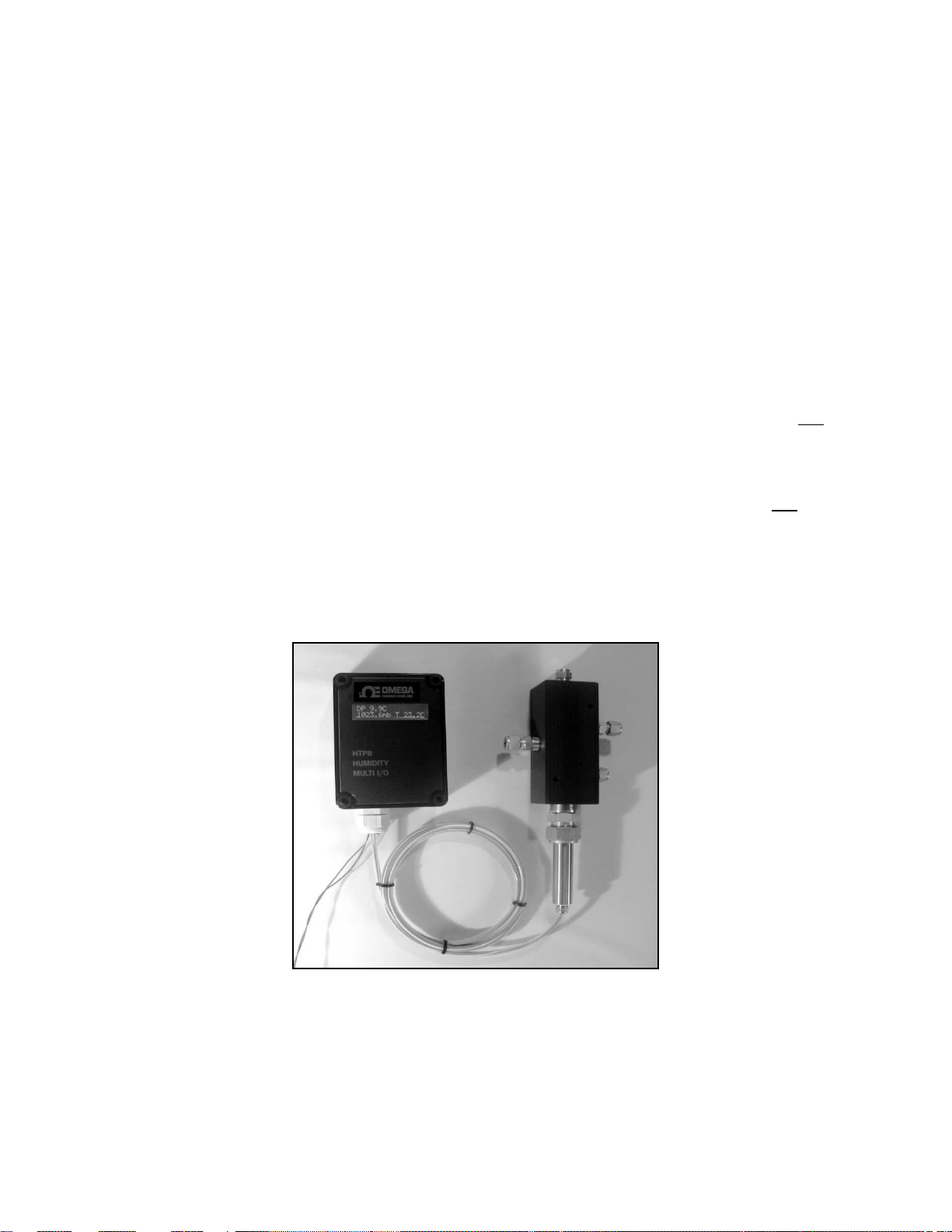
If the optional sample chamber is to be used, simply screw it down to any flat surface,
and connect ¼ inch OD tubing to the inlet and outlet compression fittings.
Figure 3-1, System with Sample Cell, ready for mounting
Page 14
12
3.3
MOUNTING THE REMOTE ELECTRONICS MODULE
MOUNTING CONSIDERATIONS
1.
If the Digital Display has been provided, is it easily visible?
2.
Is the location convenient for routing electrical wiring?
3.
Is the module within 6 feet (1.8 meters) of the Sensor location?
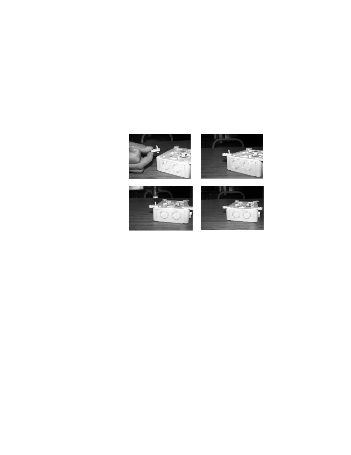
Use a small hammer to tap in the pins that hold the four corner mounting lugs in place.
See Figure 3-2 below. Mount the box to a flat surface with screws or bolts through the 4
mounting holes.
Figure 3-2 a,b,c,d
Installing Mounting Lugs
3.4
ELECTRICAL WIRING
3.3.1
PROBE ONLY
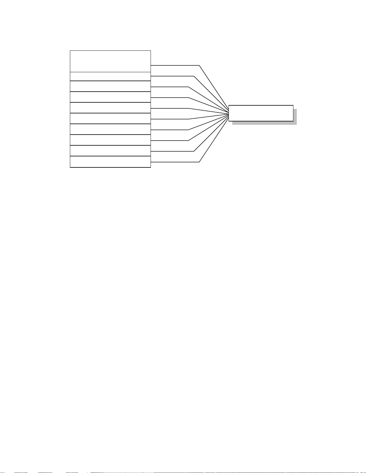
See Wiring Table 3-1 and Figure 3-3 below.
1.
Connect Power Supply wiring as shown.
2.
Connect the Analog Output wiring as shown. Three 0 to 10Vdc outputs are
available. Connect Outputs 1, 2, and 3 as required.
3.
Connect the RS-232 Serial Output if desired. Only 2 wires are required if
the output is needed for transmitting information only. A third wire is
added for bi-directional communications with the serial port.
Page 15
13
4.
ITEM
RIBBON CABLE WIRE #
Power Supply – Pos. 7
Power Supply – Neg.
1 (blue tracer)
Output 1 – Pos. 2
Output 2 – Pos. 6
Output 3 – Pos. 8
Output Common 4
Serial Output – TX 5
Serial Output – RX 3
ITEM
HX85A-COB #
Power Supply – Pos. 7
Power Supply – Neg. 1
Output 1 – Pos. 2
Output 2 – Pos. 6
Output 3 – Pos. 8
Output Common 4
Serial Output – TX 5
Serial Output – RX 3
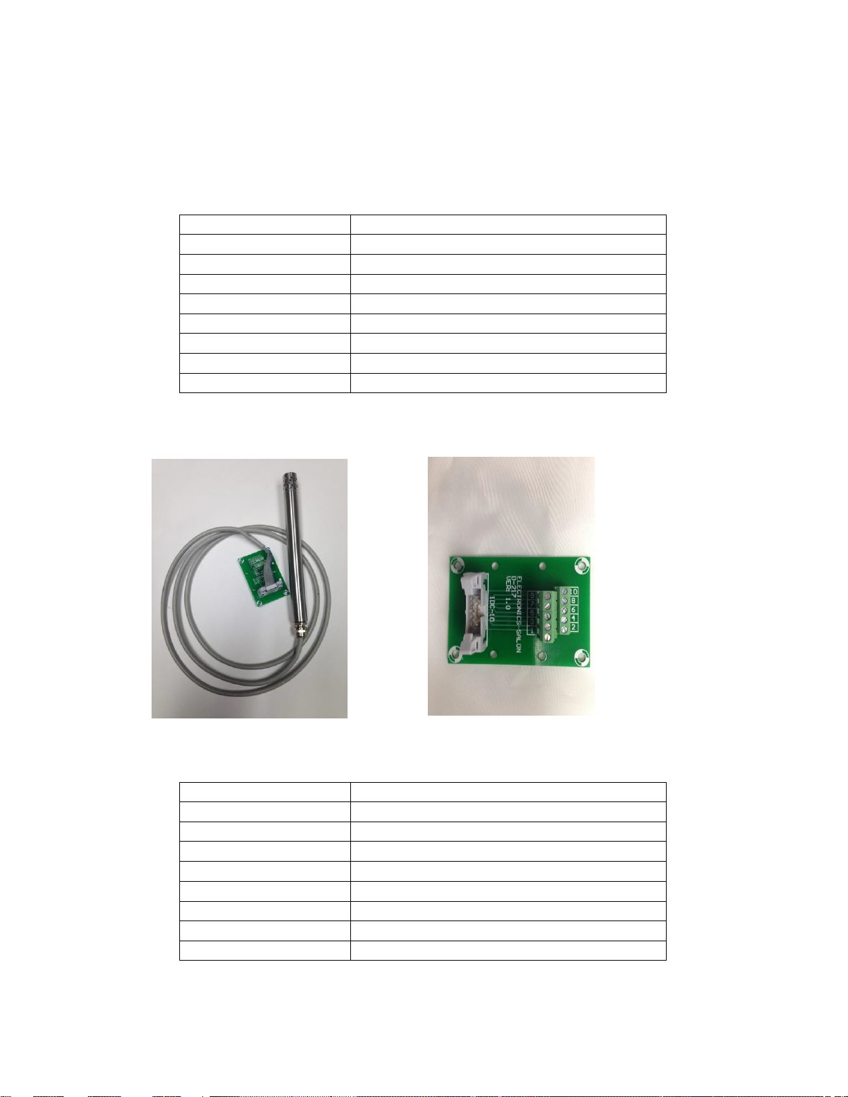
Table 3-1 HX80A Series Probe (with Ribbon Cable)
Wiring Table
HX85A-COB- connector board
X85A series connected to the HX85A-COB HX85A-COB
H
With the HX85A plugged into the HX85A-COB pinout
Page 16
14
9 NOT USED
8 OUTPUT 3 – POS.
6 OUTPUT 2 – POS.
4 OUTPUT COMMON
2 OUTPUT 1 – POS.
1 (WITH BLUE TRACER)
PWR SUPPLY – NEG.
3 SERIAL OUT -- RX
5 SERIAL OUT -- TX
7 PWR SUPPLY – POS.
10 NOT USED
Figure 3-3 HX80A Series Probe (with Ribbon Cable)
Wiring Diagram
Page 17
15
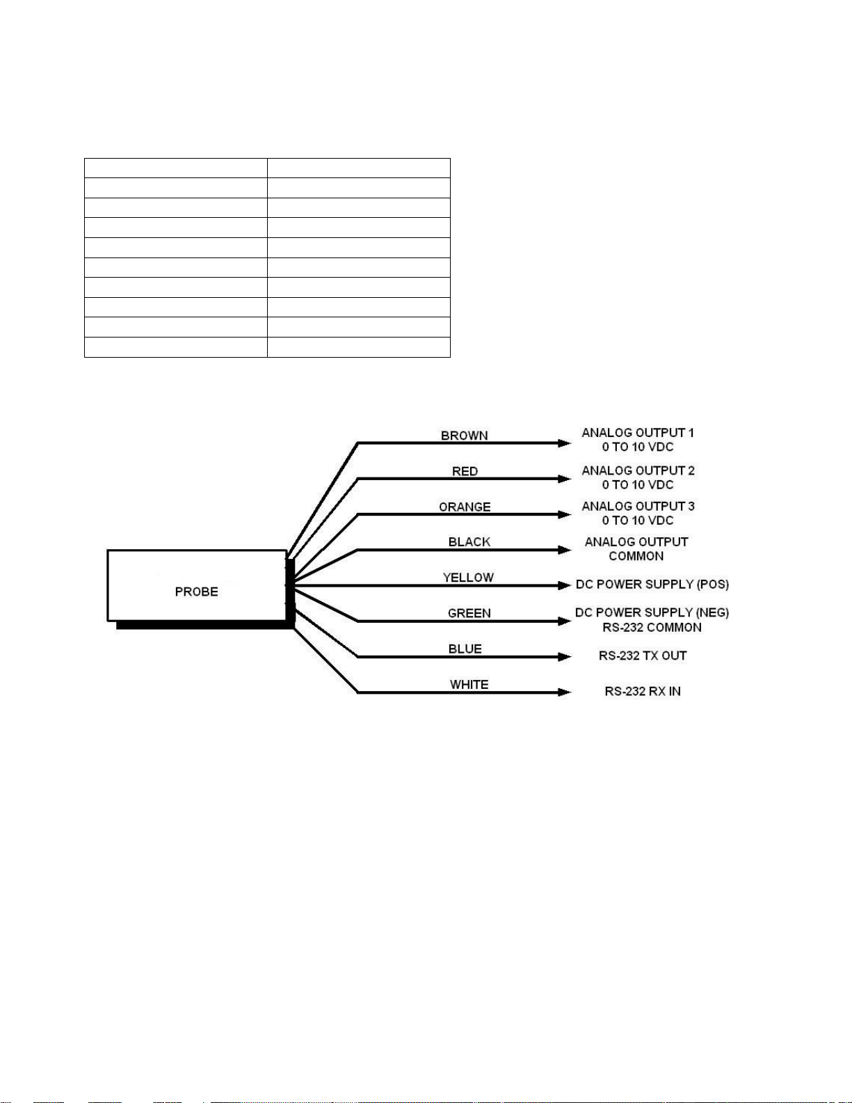
Table 3-1a HX80A Series Probe (with Discrete Wires)
ITEM
COLOR CODE
Power Supply – Pos.
Yellow
Power Supply – Neg.
Green
Output 1 – Pos.
Brown
Output 2 – Pos.
Red
Output 3 – Pos.
Orange
Output Common
Black
Serial Output – TX
Blue
Serial Output – RX
White
Serial Common
Green
Wiring Table
3.3.2
PROBE WITH ELECTRONICS MODULE
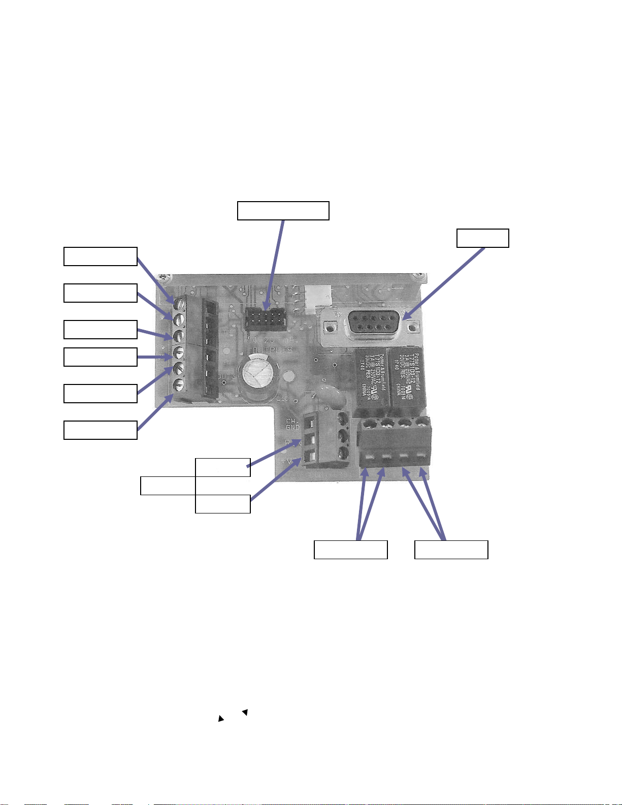
See Tables 3-2, 3-3, and Figure 3-4 below.
Notes:
1.
Cable bushings are shipped separately. Carefully tap out the desired
knockouts, and mount the bushings.
2.
We recommend that you route the Probe Cable through a bushing on the
left. Route all other wiring through the bushing on the right.
Figure 3-3a HX80A Series Probe (with Discrete Wires) Wiring Diagram
Page 18
16
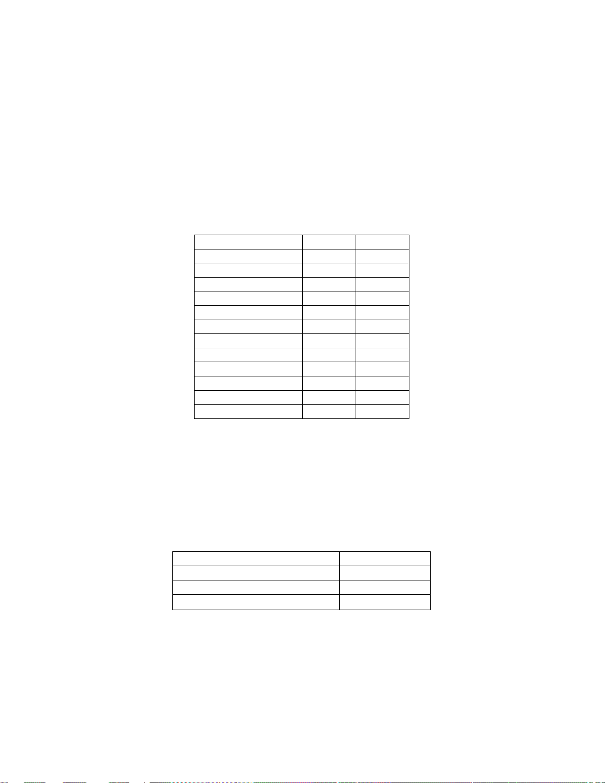
1.
ITEM
CONN.
TERM.
Power Supply (+)
J8 2
Power Supply (-)
J8 1
Analog Out 1 (+)
J9 1
Analog Out 1 (-)
J9 2
Analog Out 2 (+)
J9 3
Analog Out 2 (-)
J9 4
Analog Out 3 (+)
J9 5
Analog Out 3 (-)
J9 6
Alarm Relay 1
J2 1
Alarm Relay 1
J2 2
Alarm Relay 2
J2 3
Alarm Relay 2
J2 4
DB-9 SERIAL CONNECTOR
ITEM
Pin 2
TX
Pin 3
RX
Pin 5
RTN
Run the cable from the Probe to the connector labeled Probe Input.
2.
Wire the Power Supply as shown in Table 3-2.
3.
Wire the three 4 to 20 mA Analog Outputs and Alarm Relays as shown in Table
3-2 if desired.
4.
Connect to the RS-232C Serial Port at J6 if desired.
Table 3-2 Electronics Unit Wiring Table
Table 3-3 J6 Wiring Table
Page 19
17
NEG -
POS +
24 VDC
ALARM 1
ALARM 2
OUTPUT 1
RTN 1
OUTPUT 2
RTN 2
OUTPUT 3
Figure 3-4 Electronics Unit Wiring
PROBE CONN.
RS232
RTN 3
Page 20
18
RS-232 RS-232
(TX) (RX)
0 - 10 VDC
RH OUT
0 - 10 VDC
0 - 10 VDC
TEMP. OUT
PRESSURE OUT
SERIAL PORT
SENSOR BOARD PLUG-IN ASSY.
4.1
BASIC BLOCK DIAGRAM THEORY OF OPERATION
4.2
PROBE ASSEMBLY
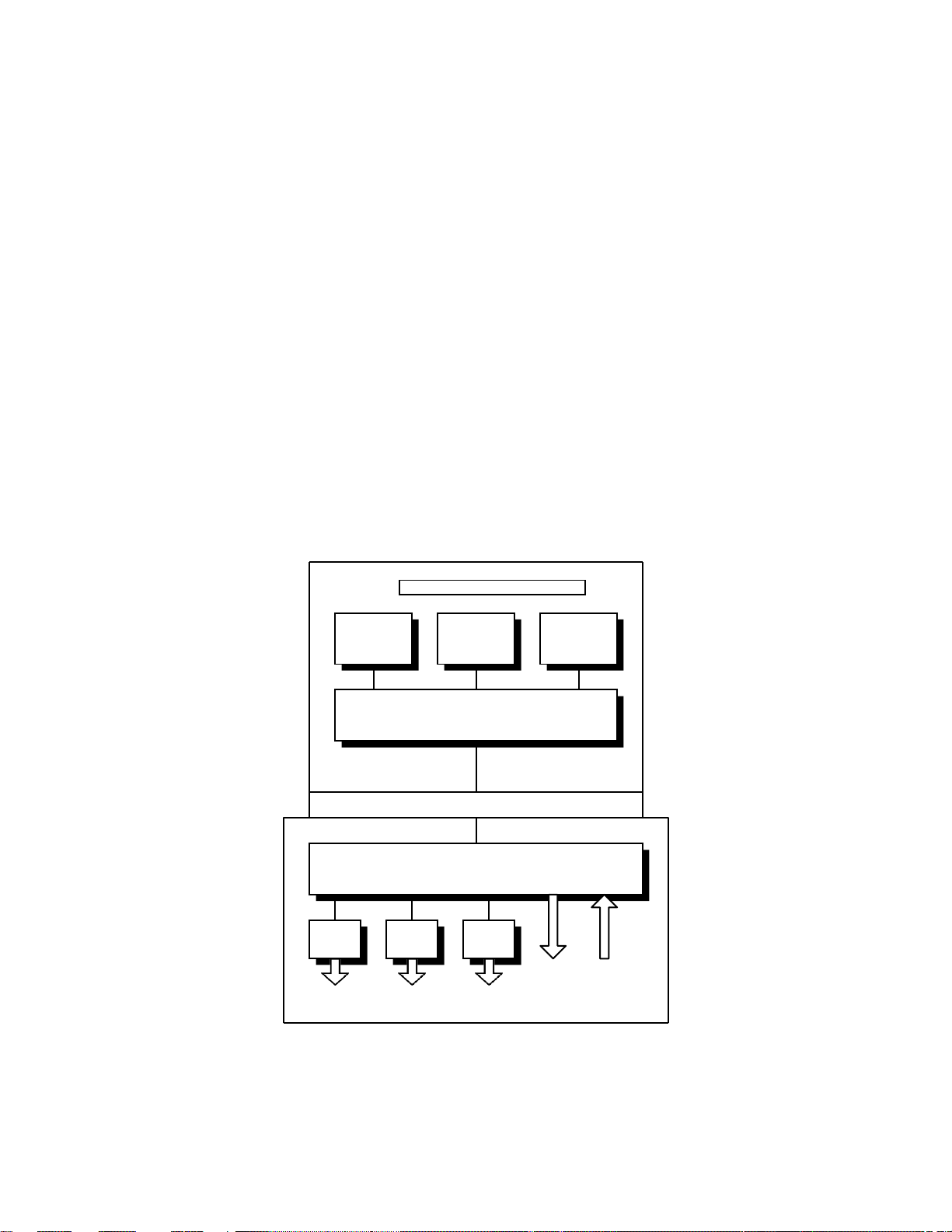
See Figure 4-1, the Probe Assy. Basic Block Diagram.
The Probe Assembly is a stand-alone, completely self-contained measuring system. All
units include the RH and Temperature Sensors, and some optional probes include a
Pressure Sensor as well. The field-replaceable Sensor Circuit Board has standardized
output levels for all three measured parameters. Therefore, boards may be quickly
replaced while in operation without the need for recalibration, maintaining full system
accuracy. The Microprocessor performs the system control, parameter calculation, and
serial digital communications. Digital-to-Analog (D-A) conversion provides three 0 to 10
Vdc linear Analog Outputs corresponding to the measured and/or calculated
parameters.
The serial digital RS-232 interface is bi-directional, allowing the user to not only receive
and record measured information, but to remotely control output scaling, alarm relay
setpoints, and other functions as well.
RH
SENSOR
NORMALIZATION - CALIBRATION
SENSOR BOARD PLUG-IN CONNECTOR
TEMP.
SENSOR
STAGE
MICROPROCESSOR
D-AD-AD-A
PRESSURE
SENSOR
Figure 4-1 Basic Block Diagram, Probe Assy
Page 21

19
4.3
HX86A-DIS ELECTRONICS MODULE
Although the Probe may be used as a stand-alone measuring device (HX85A), it also
may be connected to the type DIS remote display unit, for additional capability. This
combination is called the HX86A. A complete HX86A system consists of the Probe, the
interconnecting 6 foot (1.8 meter) cable, and the electronics module. Outputs of the unit
include a Serial Port, two Alarm Relays and three 4 to 20 mA Analog Outputs. A twoline LCD Digital Display is also included.
4.4
THE COMPLETE HX86A SYSTEM
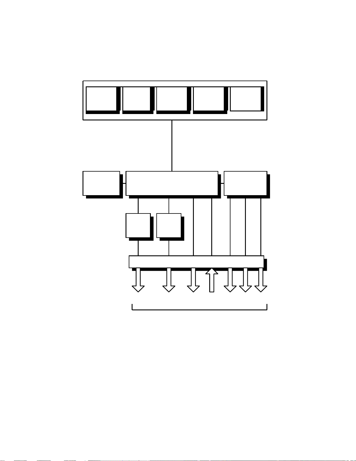
Figure 4-2 is a basic block diagram of the complete Humidity, Temperature and
Pressure measuring system. The remote Probe is connected, via the attached cable, to
the electronics module. The system is completely controlled by the microprocessor in
this module.
The three sets of analog voltage outputs from the Probe are routed through the Analog
Scaling and Selection stage. The scaling of these output signals may be programmed
by the user to any desired range by using the RS-232 Serial Port. The bi-directional
RS-232 is brought out to a connector in the electronics module. The user can also
program the two Alarm Relay set points via this digital interface. The built-in LCD
Digital Display, which provides information on all measured parameters, is also
controlled by the microprocessor. In addition, the microprocessor is used to calculate
other parameters than those directly measured by the sensors in the Probe. These may
be shown on the Digital Display, and they are also available on both the analog and
digital (RS-232) outputs. The Alarm Relays may also be set for these calculated values.
Page 22
20
HTPB PROBE ASSY.
6 FT. SENSOR CABLE
ANALOG
SELECTION
Figure 4-2 System Basic Block Diagram
R
R
SERIAL
(TX) (RX)
ANALOG
(0 - 10V X3)
RH
SENSO
DIGITAL
DISPLAY
TEMP.
SENSO
ALARM
RELAY
#1
PRESSURE
SENSOR
(OPTION)
MICROPROCESSOR
ALARM
RELAY
#2
ELECTRICAL CONNECTORS
PORT
OUTPUT S
SCALING
AND
ALARM
ALARM
1
2
USER INTERFACE
RS-232
(TX) (RX)
ANALOG OUTPUTS
1 2 3
Page 23

21
5.1
OPERATION
5.2
INITIAL BENCH TESTING
New units may be tested on the bench before installation, if desired.
For units consisting of the Probe only –
1.
Connect a proper Power Supply to the correct wires.
Caution: Observe polarity!
2.
Using a DC Voltmeter, measure the 0 to 10 Vdc Output and confirm that it
corresponds to the room condition. (Humidity, Temperature, etc.)
For systems consisting of the Probe and the Electronics Unit –
1.
Connect the Probe to the Electronics Module.
2.
Connect a proper Power Supply to the correct terminals.
Caution: Observe polarity!
3.
Measure the 4 to 20 mA Output as above, or read the Digital Display.
Confirm that the reading corresponds to the room condition. (Humidity,
Temperature, etc.)
5.3
NORMAL OPERATION
Note:
This section assumes that all required electrical wiring and mounting has
been completed. See the Installation section for further information if
necessary.
Use of the HX80A series of probes is extremely simple. There are no controls to
operate during normal use, as these devices are designed for long-term unattended
operation. With the Analog Outputs, Digital Outputs, and/or Alarm Relays connected to
a Data Acquisition System, Recorder, Process Controller, Computer, or Terminal, the
user has only to periodically monitor the system for normal operation.
5.4
FACTORY DEFAULT RANGES
The scaling of the default measurement ranges may be changed in the field via the
Serial Port if required. See Section 5.4 below for range-changing instructions.
The following ranges are set at the Factory. They correspond to the three separate 0 to
10 Vdc analog outputs that are provided. The scaling of these ranges may be changed
in the field via the Serial Port if required.
Page 24
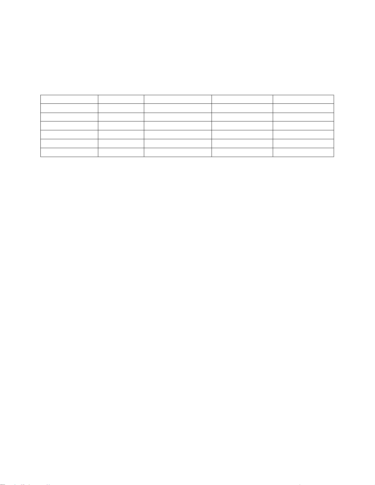
22
MODEL
R.H.
TEMP.
PRESSURE
DEW POINT
HX85A
0 to 100%
-20 to 80OC/120 OC
N/A
-60 to 40˚C
HX85BA
0 to 100%
-20 to 80OC/120 OC
750 to 1100 mb
HX85PA
0 to 100%
-20 to 80OC/120 OC
0 to 200 psia
HX86A
0 to 100%
-20 to 120OC
N/A
-60 to -40˚C
HX86BA
0 to 100%
-20 to 120OC
750 to 1100 mb
HX86PA
0 to 100%
-20 to 120OC
0 to 200 psia
Notes:
Table 5-1 Standard Output Scaling
1.
Although the Factory default range for the HX85BA, and the
HX86BA is 750 to 1100 mb, it can be reprogrammed in the field over a
range of 10 to 1100 mb.
2.
If you have the Type DIS Humidity Multi-I/O accessory, the Analog
Outputs are 4 to 20 mA.
Page 25
23
5.5
USING THE RS-232C SERIAL PORT TO PROGRAM YOUR
SETTINGS
5.4.1
SERIAL PORT SETUP
Plug a standard RS-232 cable into the DB-9 connector on the circuit board in the Type
DIS Humidity Multi I/O Electronics Unit. Plug the other end into your terminal or
computer. Use a Terminal Emulation program such as Hyperterminal. Program the
Hyperterminal settings as follows:
• Baud Rate: 19.2K
• Data Bits: 8
• Parity None
• Stop Bit 1
• Flow Control None
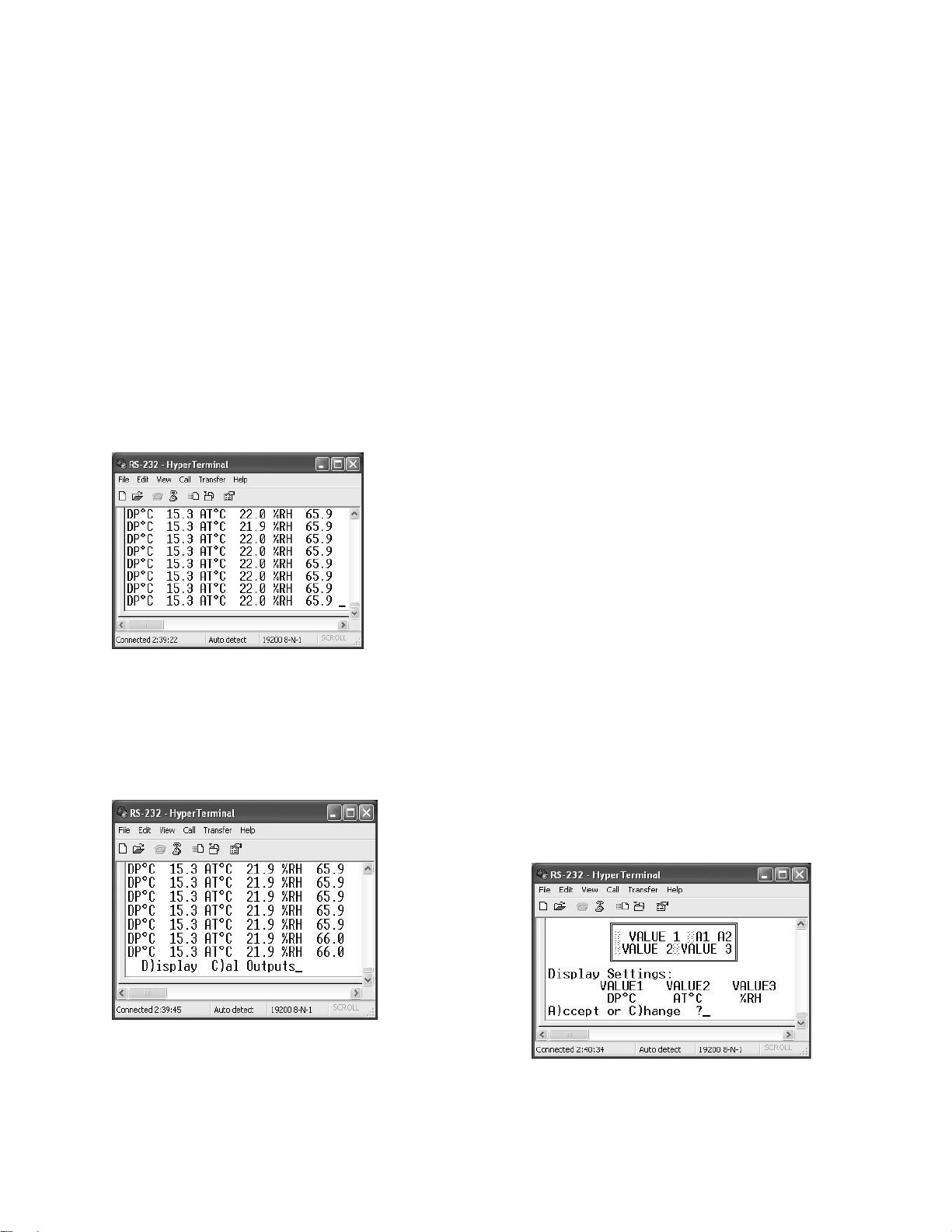
You should now see flowing data on your monitor,
displaying the same information as the Multi I/O front
panel Digital Display, with a rapid update rate. If you do
not, check your serial port settings and connections.
NOTE: WHEN PROGRAMMING ALPHABETIC CHARACTERS,
USE UPPER CASE ONLY.
5.4.2
CHANGING THE DIGITAL DISPLAY
You can select any measured or calculated
parameters to appear on the front panel Digital
Display. Proceed as follows:
Press the
“Escape” key
on your
keyboard.
You will see
“D)isplay C)al
Outputs” as
shown here.
Press “D”, selecting to change the Display. (We
will C)alibrate the Outputs later.) You will then be given a choice whether to keep the
present settings or to change them. For this example, we will C)hange them. Press
Page 26
24
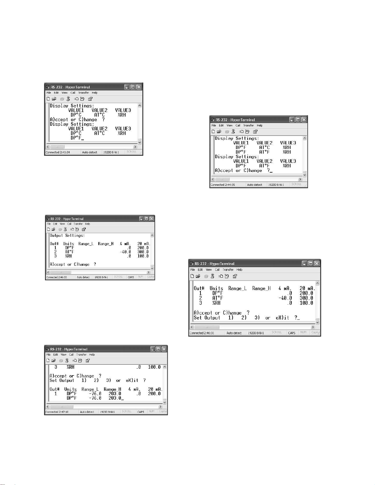
“C”. You can then select the parameter to insert by cycling through the options using
the Space Bar. In this case, we will change VALUE 1, the Dew Point reading, from
DPoC to DPoF. Press Enter to save your change and advance to the next value. Next,
do the same for Air Temperature. When completed, press Enter again to save and
advance. For this example, we will choose not to
change the %RH value. Instead, press “X” for eX)it.
When programming is completed, press “A” to
accept the changes.
5.4.3
CHANGING THE OUTPUT RANGES
The next window to be seen will be the Output
Settings screen. Here, you can modify the 4 to 20
mA Analog Output ranges. To enter this mode,
press “C” for C)hange. You will see the Set Output
screen shown here.
To change Output 1, select “1”. You will see
this screen, which shows the present settings
for Output 1.
Page 27
25
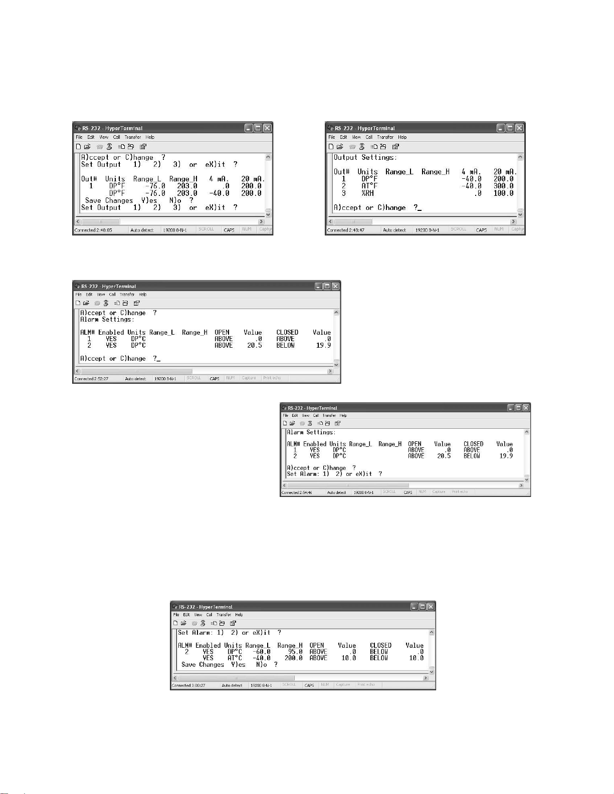
Example: We would like to change DPoF to a range of -40 to 200 oF. Press Enter.
Enter -40. Press Enter again. Enter 200. Press Enter again. To Save the Changes,
press “Y” for Y)es. To accept the changes, press “A” for A)ccept.
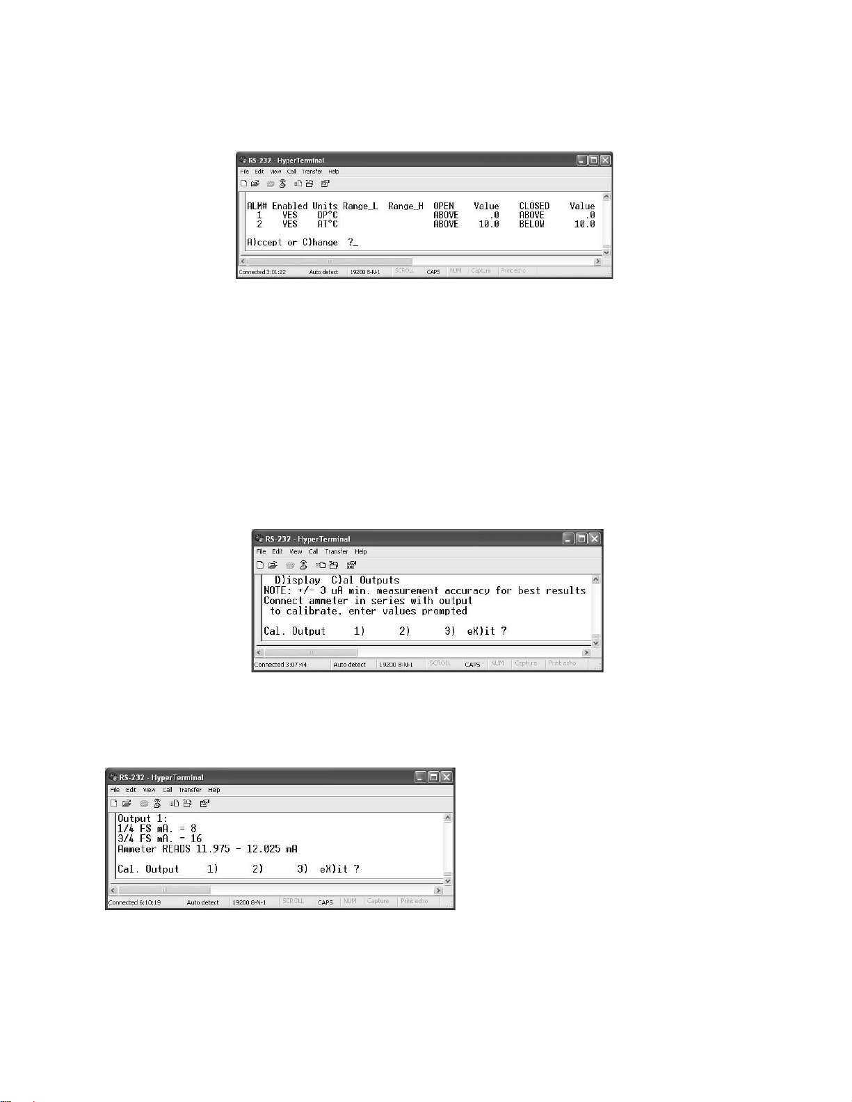
5.4.4
PROGRAMMING THE ALARM RELAYS
The system will then step to the
Alarm Relay mode. The two relays
are Form A, (single-pole, singlethrow), normally open. You can
independently program the “ON”
point and the “OFF” point for each
relay. To enter the menu, press
“C” for C)hange.
We would like to change Alarm 2 to
these parameters:
Open > a reading of 10 oC
Close < a reading of 10 oC
NOTE: IN ACTUAL OPERATION YOU SHOULD PROGAM IN A SMALL OVERLAP,
SO THAT THE RELAY DOES NOT CHATTER WHEN THE MEASURED READING IS
EXACTLY AT THE SETPOINT. THIS IS CALLED “HYSTERESIS.”
Press “2” to set Alarm 2. You will note that Alarm 2 is set for Air Temperature, AToC.
Under OPEN, insert 10 and press “Enter.” Under CLOSED, insert 10 and press “Enter.”
Page 28
26
You will be asked to Save the Changes. Press “Y” for Y)es.
Then, press “A” for A)ccept.
The program will then automatically return to the normal mode, displaying data that is
continuously updated.
5.4.5
CALIBRATING THE ANALOG OUTPUTS
If you have a precise milliammeter, you can easily calibrate the three 4 to 20 mA analog
outputs. In order to utilize this convenient capability, connect the meter in series with
one of the analog outputs and the load.
Press the “Escape” key on your keyboard, which will interrupt the data stream and give
you the choice of D)isplay or C)al Outputs. Select “C”.
In order to calibrate Output 1, press “1”. You will then be able to insert the desired
current value at the ¼ FS (25% of Full Scale) point and at the 3/4FS (75% of Full Scale)
point. For 4 to 20 mA, 1/4FS is 8 mA, and 3/4FS is 16mA.
Insert these values, pressing “Enter”
after each one. You will then see a
range of what the milliammeter should
read in order to attain the desired
accuracy.
Then select “X” for eX)it. The system
will now return to the normal data
reading mode.
Page 29
27
6.1
MAINTENANCE
6.2
SENSOR CIRCUIT BOARD
Inside the barrel of the Sensor probe, mounted directly at the tip, is the plug-in sensor
circuit board. This board has been calibrated at the Factory for a standard output level.
Since all boards have been calibrated for the same normalized level, they may be
replaced in the field without the requirement for recalibration, while maintaining the full
published system accuracy specification.
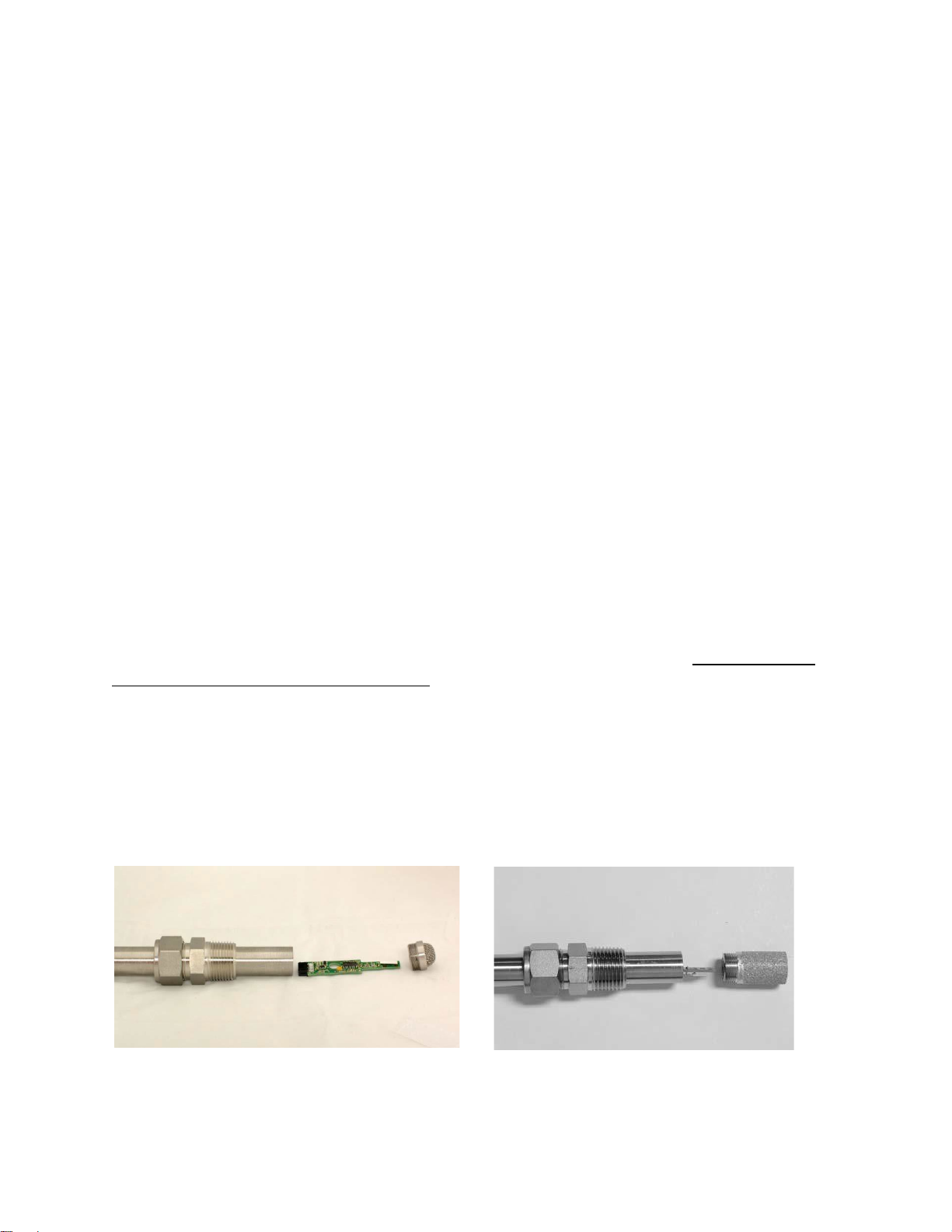
6.1.1 REPLACING THE SENSOR CIRCUIT BOARD
The HX85A and HX86A series the filter cover is a screw on cover). It must be
removed in order to gain access to the Sensor board.
.
Note: The small humidity sensor can be seen mounted near the tip of the board.
This is fragile. Take care not to break it during board removal or installation.
6.1.3 SENSOR REASSEMBLY
Carefully plug the new sensor circuit board into the socket, noting that it is installed at
the correct angle and properly aligned.
Figure 6-2 Sensor Exploded View
for the HX85A or HX86A series
Page 30

28
7.0 SPECIFICATIONS
Note: See Table 2-2 for actual measurement ranges.
HX85A (Sensor Only)
Measured Parameters – RH/Temp.
RH Accuracy – +/- 1% RH
Temp. Accuracy – +/- 0.5oC
Output Information – RH, Temp., DP
Electrical Outputs – 0 to 10 Vdc (X3)
RS-232C
HX85BA (Sensor Only)
Measured Parameters – RH/Temp./Barometric Pressure
RH Accuracy – +/- 1% RH
Temp. Accuracy – +/- 0.5oC
Pressure Accuracy – +/- 5 mb
Output Information – RH, Temp., Pressure
Electrical Outputs – 0 to 10 Vdc (X3)
RS-232C
HX85PA(Sensor Only)
Measured Parameters – RH/Temp./Pressure
RH Accuracy – +/- 1% RH
Temp. Accuracy – +/- 0.5oC
Pressure Accuracy – +/- 0.75 psi
Output Information – RH, Temp., Pressure
Electrical Outputs – 0 to 10 Vdc (X3)
RS-232C
HX86A (Sensor with Electronics Module)
Measured Parameters – RH/Temp.
RH Accuracy – +/- 1% RH
Temp. Accuracy – +/- 0.5oC
Output Information – RH, Temp., DP
Electrical Outputs – 4 to 20 mA (X3)
RS-232C
Alarm Relays (X2)
Digital Display – LCD, 2-line
Page 31

29
HX86BA (Sensor with Electronics Module)
Measured Parameters – RH/Temp./Barometric Pressure
RH Accuracy – +/- 1% RH
Temp. Accuracy – +/- 0.5oC
Pressure Accuracy – +/- 5 mb
Output Information – RH, Temp., Pressure
Electrical Outputs – 4 to 20 mA (X3)
RS-232C
Alarm Relays (X2)
Digital Display – LCD, 2-line
HX86PA (Sensor with Electronics Module)
Measured Parameters – RH/Temp./ Pressure
RH Accuracy – +/- 1% RH
Temp. Accuracy – +/- 0.5oC
Pressure Accuracy – +/- 0.75 psi
Output Information – RH, Temp., Pressure
Electrical Outputs – 4 to 20 mA (X3)
RS-232C
Alarm Relays (X2)
Digital Display – LCD, 2-line
Electrical Outputs
Systems with Probe only –
0 to 10 Vdc (X 3) @ 10 mA max.
RS-232C (bi-directional)
Systems with Probe and Electronics Unit—
4 to 20 mA (X3) into 500 Ω max.
Alarm Relay (X2) Form A (SPST, NO) rated at 3A/250 Vac
RS-232C (bi-directional)
Serial Output (All Units)
RS-232C to DTE device. 19.2 kilobaud, 8 bits data, 1 stop bit, no parity
Power Requirements
18 to 30 Vdc unregulated, 50 mA max.
Page 32

30
Dimensions
Remote Sensor – Diameter: ¾ in. OD (1.9 cm)
Cable Length – 6 feet (1.8 meters)
Consult Factory for longer lengths.
Electronics Module –
Outside Dimensions (HWD)
Mounting Centers
Sensor Pressure Rating
200 psia maximum
Sensor Sintered Filter
Material – Stainless Steel
Porosity – 40 microns
Length: 8 inches (20.3 cm)
5.1 X 3.7 X 2.2 inches (13 X 9.4 X 5.6 cm)
4.52 X 3.11 inches (11.5 X 7.9 cm)
Page 33

31
Notes
 Loading...