

Page 1
UNRESTRICTED
TM
U
ser’s Guide
Shop online
at
omega.com
e-mail: [email protected]
For latest product
manuals:
www.omega.com/en-
us/pdf-manuals
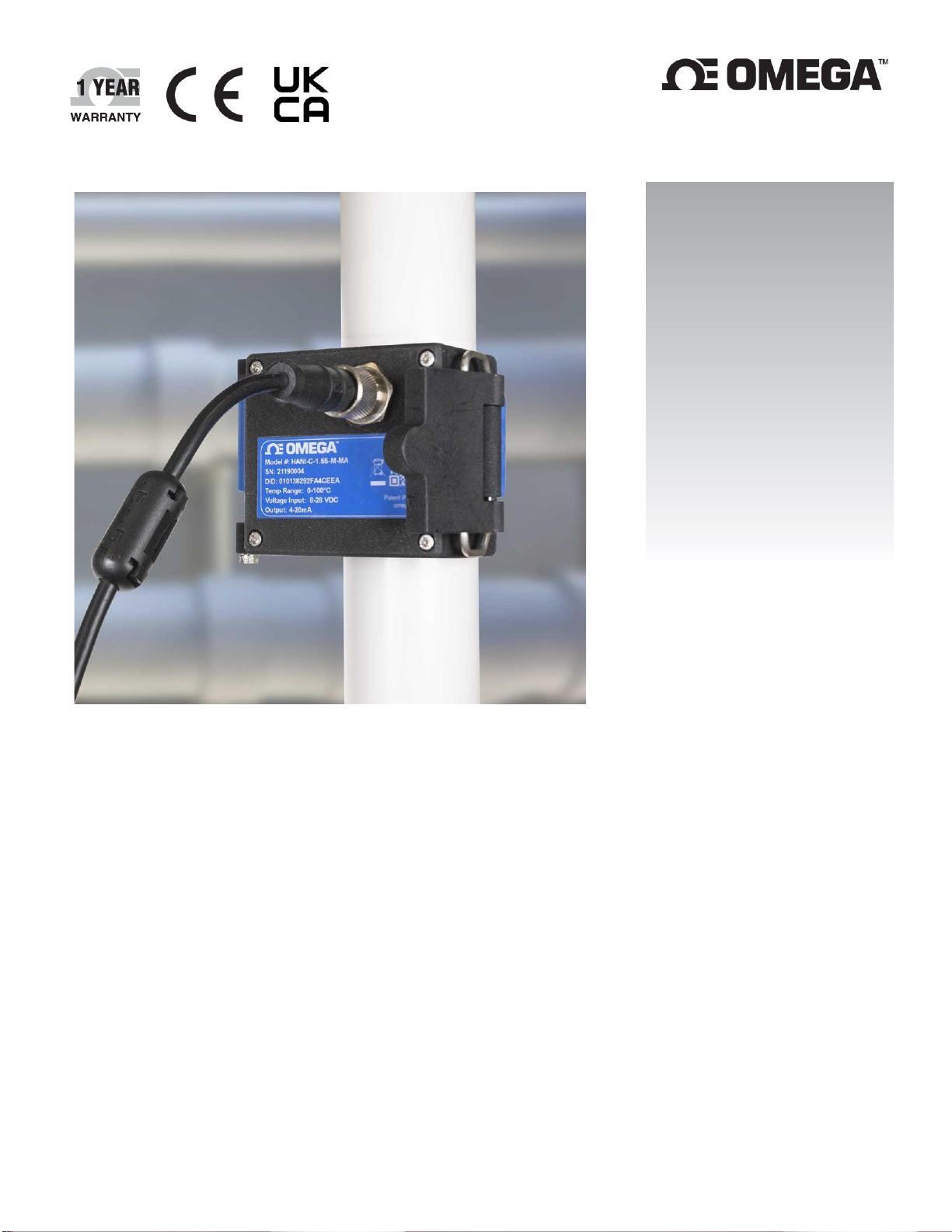
HANI™ Clamp Temperature
Sensor
High Accuracy Non-Invasive Clamp
Temperature Sensor
Page 2

2 | H A N I ™
UNRESTRICTED
The information contained in this document is believed to be correct, but OMEGA accepts no liability for any errors it contains and reserves the right to
alter specifications without notice.
omega.com [email protected]
Omega Engineering, Inc:
800 Connecticut Ave. Suite 5N01, Norwalk, CT 06854, USA
Toll-Free: 1-800-826-6342 (USA & Canada only)
Customer Service: 1-800-622-2378 (USA & Canada only)
Engineering Service: 1-800-872-9436 (USA & Canada only)
Tel: (203) 359-1660
e-mail: [email protected]
Fax: (203) 359-7700
Omega Engineering,
Limited:
1 Omega Drive, Northbank,
Irlam Manchester M44 5BD
United Kingdom
Omega Engineering,
GmbH:
Daimlerstrasse 26 75392
Deckenpfronn Germany
Page 3

3 | H A N I ™
UNRESTRICTED
Table of Contents
Table of Contents ............................................................................................................................................. 3
1. Notes, Warnings, and Cautions .................................................................................................................. 5
2. Introduction .............................................................................................................................................. 6
2.1 HANI™ Clamp Temperature Sensor Mounting ...................................................................................................7
3. Wiring Diagram ......................................................................................................................................... 8
3.1 M12 8-Pin Connector ........................................................................................................................................8
3.1.1 4-20 mA Process Signals ........................................................................................................................................ 8
4. 4-20 mA Plug and Play ............................................................................................................................... 8
5. SYNC Configuration.................................................................................................................................... 9
5.1 Configuring Inputs ............................................................................................................................................9
5.1.1 Calibration ........................................................................................................................................................... 11
5.1.2 Setting Alarms ..................................................................................................................................................... 12
5.2 Configuring Device Settings ............................................................................................................................ 13
5.2.1 Transmit Interval ................................................................................................................................................. 13
5.2.2 Setting/Changing Passwords ............................................................................................................................... 13
5.3 Data Logging .................................................................................................................................................. 15
6. 4-20mA Loop-Powered Output ................................................................................................................ 16
6.1 Sensor Mapping ............................................................................................................................................. 16
6.1.1 4-20 mA Outputs Sensor Mapping ...................................................................................................................... 17
7. Pairing to an Omega Link Gateway ........................................................................................................... 18
7.1 Wireless Pairing ............................................................................................................................................. 18
7.2 Wired Pairing ................................................................................................................................................. 18
8. Specifications .......................................................................................................................................... 19
9. Appendix: HANI™ Clamp Temperature Sensor Input Interface .................................................................. 20
9.1 Register Base Addresses ................................................................................................................................. 20
9.2 HANI™ Clamp Temperature Sensor Temperature Input Interface ..................................................................... 20
9.2.1 Sensor Input Descriptor ...................................................................................................................................... 20
9.2.2 Sensor Temperature Parameters ........................................................................................................................ 22
9.2.3 Sensor User Calibration Parameters ................................................................................................................... 23
9.2.4 Sensor IPSO Definition ........................................................................................................................................ 23
9.3 DIO Interface.................................................................................................................................................. 25
9.3.1 DIO Descriptor ..................................................................................................................................................... 25
9.3.2 DIO IPSO Definition ............................................................................................................................................. 27
9.4 Output Configuration Registers....................................................................................................................... 28
9.4.1 Scaling Minimum / Maximum Values ................................................................................................................. 28
9.4.2 Output Values ..................................................................................................................................................... 28
9.4.3 Output Names ..................................................................................................................................................... 29
9.5 4-20 mA Output Configuration ........................................................................................................................ 29
9.5.1 High Range / Low Range ..................................................................................................................................... 30
9.5.2 System Error ........................................................................................................................................................ 30
9.5.3 Output Type ........................................................................................................................................................ 30
9.5.4 Mapping Enabled ................................................................................................................................................ 30
9.5.5 Output Mapping .................................................................................................................................................. 30
9.5.6 Scaling Minimum/Maximum Values ................................................................................................................... 30
Page 4

4 | H A N I ™
UNRESTRICTED
9.5.7 4-20 mA Loop Powered Error.............................................................................................................................. 30
9.6 Digital Output Configuration ........................................................................................................................... 31
9.6.1 Rate ..................................................................................................................................................................... 31
9.6.2 Output Type ........................................................................................................................................................ 32
9.6.3 Active State ......................................................................................................................................................... 32
9.6.4 Mapping Enabled ................................................................................................................................................ 32
9.6.5 Output Mapping .................................................................................................................................................. 32
Page 5
5 | H A N I ™
UNRESTRICTED
1. Notes, Warnings, and Cautions
If the equipment is used in a manner not specified in this manual, the protection by the equipment may be
impaired.
Do not operate the equipment in flammable or explosive environments.
It is important to read and follow all precautions and instructions in this manual before operating or commissioning
this device as it contains important information relating to safety and EMC. Failure to follow all the safety
precautions may result in injury and/or damage to your equipment.
The following labels identify information that is especially important to note:
Note: Provides you with information that is important to successfully setup and use the device.
Caution or Warning: Tells you about the risk of electrical shock.
Caution, Warning, or Important: Tells you of circumstances that can affect the functionality of the instrument and
must refer to accompanying documents.
Page 6
UNRESTRICTED
2. Introduction
The Omega Engineering innovative technology for non-invasive temperature sensing delivers high accuracy and fast
response times without the costs of installation, damage, replacement, and calibration that occur with an
immersion sensor. The HANI™ Clamp Temperature Sensor makes measuring the temperature of a fluid moving
through a pipe easier than ever. There is no cutting or drilling necessary. Simply clamp the sensor onto the outside
of the pipe and start measuring the temperature of the fluid inside the pipe.
The HANI™ Clamp Temperature sensor is designed to be used in conjunction with a 4-20 mA connection for plugand-play analog output, or with an Omega Link Smart Interface to utilize customizable features using Omega’s SYNC
configuration software through an integrated M12 connector.
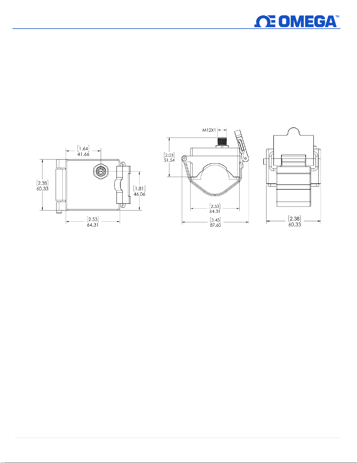
Figure 1: HANI™ Mechanical Dimensions in Inches
6 | H A N I ™
Page 7
7 | H A N I ™
UNRESTRICTED
2.1 HANI™ Clamp Temperature Sensor Mounting
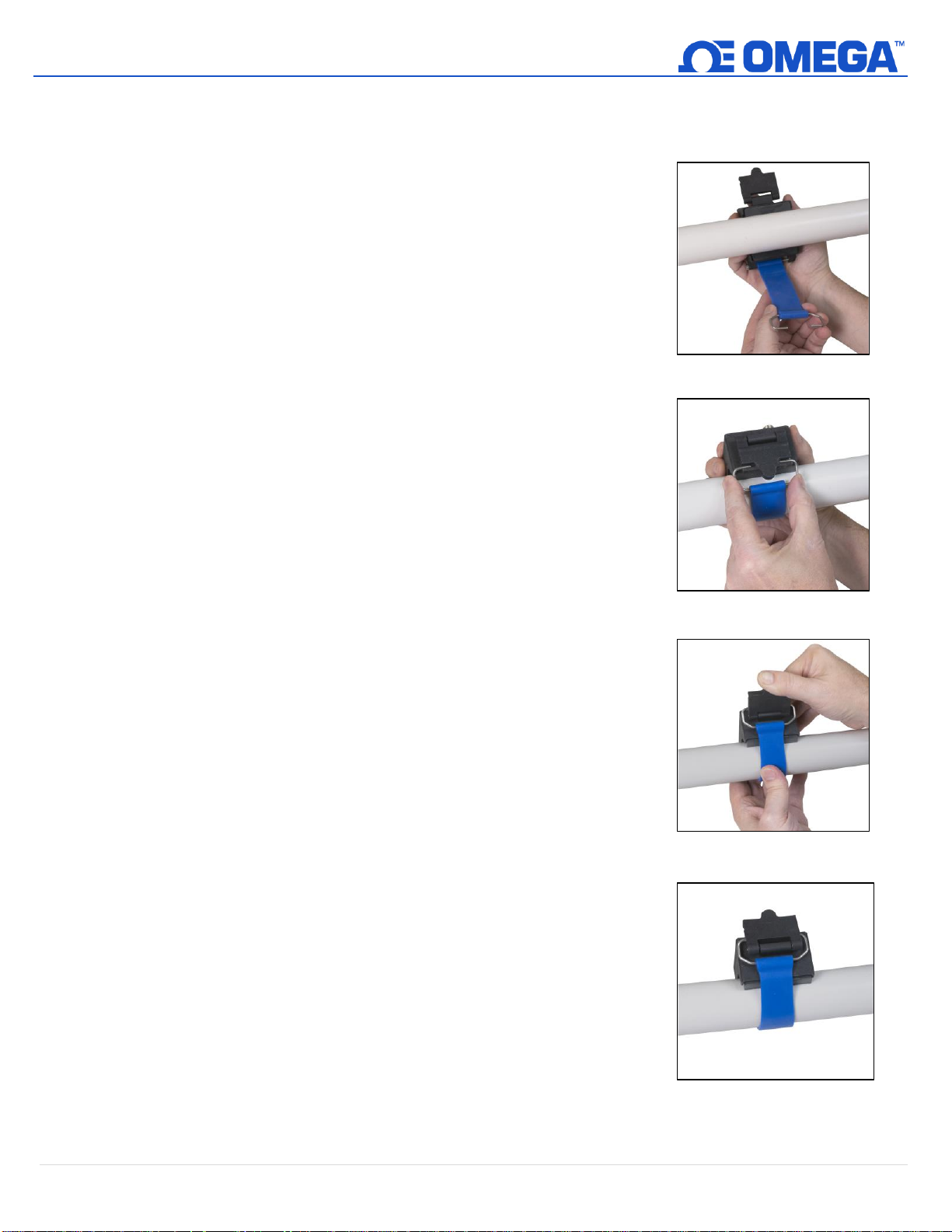
Setting up a HANI™ Clamp Temperature Sensor in the field is quick and easy. Follow the instructions below:
Step 1: Mount the HANI™ Clamp Temperature Sensor housing on the pipe
you will be measuring. Ensure the device is mounted on the side or
the underside of a horizontal pipe to ensure you are sensing an area
full of liquid.
Step 2: Slide the clasp end into the side channels of the cam lever.
Step 3: Pull the cam mechanism to tighten the HANI™ Clamp Temperature
Sensor securely on the pipe.
Once the cam mechanism is secured on the pipe, the mounting process is
complete.
Figure 2: Mount the HANI™
Sensor
Figure 3: Adjust the Clasp and
Cam Lever
Figure 4: Secure the HANI™ Sensor
Figure 5: A successfully mounted
HANI™ Sensor
Page 8
8 | H A N I ™
UNRESTRICTED
3. Wiring Diagram
3.1 M12 8-Pin Connector
The HANI™ Clamp Temperature Sensor connects to a 4-20 mA connection or Omega Link Smart Interface through
an M12 8-pin female mating connector. The connector supports the required I2C + INTR signal lines and the Smart
Probe power signals.
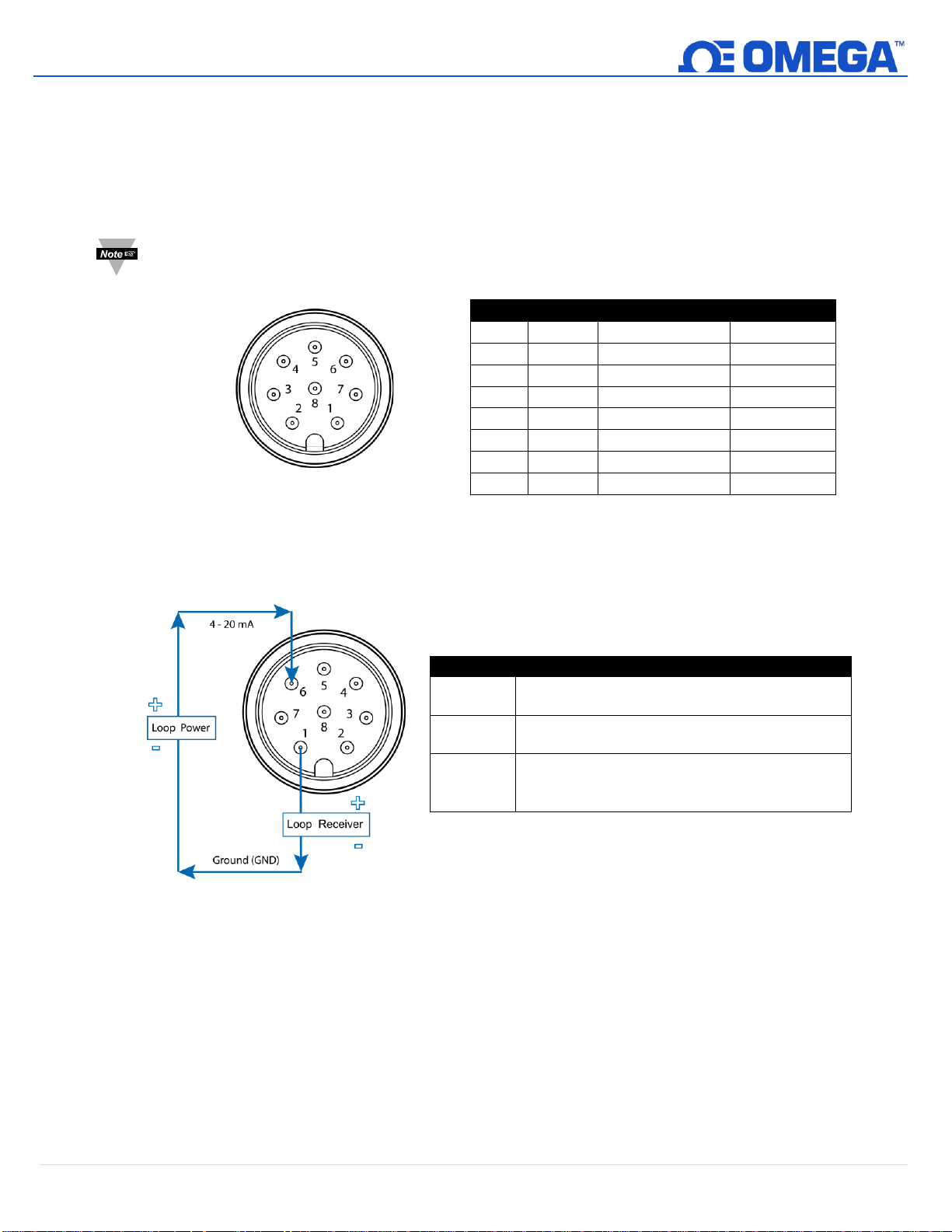
Note: The image below is a view of the open end of the Female Mating M12 8-Pin Connector and not the
integrated male connector on the HANI™ Clamp Temperature Sensor.
3.1.1 4-20 mA Process Signals
Refer to the following wiring diagram of the HANI™ Clamp Sensor itself in this section to setup 4-20 mA
process signals.
Figure 7: 4-20 mA Process diagram of the
Integrated male HANI™ Connector
4. 4-20 mA Plug and Play
The HANI™ Clamp Temperature Sensor can easily be integrated into your existing analog system in a few steps. To
immediately make use of the 4-20 mA plug and play feature, follow these instructions:
Step 1: Mount and strap the HANI™ Clamp Temperature Sensor on the pipe you will be measuring.
Step 2: Attach an 8-pin female M12 connector to your 4-20 mA analog cable (see the HANI™ Clamp Temperature
Sensor wiring diagram above – only pins 1 & 6 are needed).
The HANI™ Clamp Temperature Sensor will immediately begin reporting temperature readings.
Name
Function
Wiring
Pin 1
Loop -
4-20mA Return
4-20 mA
Pin 2
INTR
Interrupt Signal
Omega Link
Pin 3
SCL
I2C Clock Signal
Omega Link
Pin 4
SDA
I2C Data Signal
Omega Link
Pin 5
Shield
Shield Ground
Omega Link
Pin 6
Loop +
4-20mA Source
4-20 mA
Pin 7
GND
Power Ground
Omega Link
Pin 8
VCC
Power Supply
Omega Link
Name
Description
Loop
Power
Provides “excitation” voltage to the sensor,
typically 12-24 VDC.
Sensor
Controls the current that flows through the circuit
based on the measured value.
Loop
Receiver
Converts the 4-20 mA signal and displays or
transmits the measured value. This includes PID
controllers and programmable logic controllers.
Figure 6: Female Mating
M12 8-Pin Connector
Page 9
9 | H A N I ™
UNRESTRICTED
5. SYNC Configuration
Important: SYNC configuration is only necessary if you will be changing the following: Pipe Material, Pipe Schedule,
Pipe Wall Thickness, Pipe Outer Diameter (O.D.), Pipe Material Thermal Conductivity, or to scale Output Readings.
Ensure Omega’s SYNC configuration software is downloaded, setup, and running before continuing. Ensure you
have an Omega Link Smart Interface, such as an IF-001 or IF-006, compatible with your HANI™ Clamp Temperature
Sensor.
Important: If the HANI™ Clamp Temperature Sensor is being powered with a 4-20 mA connection and will be
configured using SYNC simultaneously, a USB Isolator must be used between the user PC and the HANI™ Clamp
Temperature Sensor to avoid false readings and potential damage to the unit.
The HANI™ Clamp Temperature Sensor can be configured using Omega’s SYNC configuration software when the
HANI™ Clamp Temperature Sensor is connected through an Omega Link Smart Interface to a computer running
SYNC. Depending on the Omega Link Smart Interface being used, the connection process may vary slightly. Refer to
the User Documentation of the Omega Link Smart Interface you are using.
Once your HANI™ Clamp Temperature Sensor is connected to SYNC, you will immediately see readings appear on
the SYNC interface.
5.1 Configuring Inputs
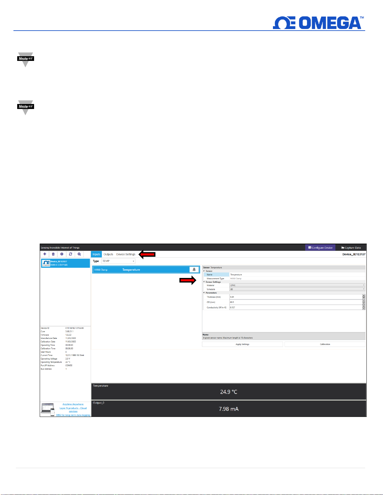
Omega’s SYNC configuration software can be used to configure the HANI™ Clamp Temperature Sensor to suit your
application parameters. To configure a HANI™ Clamp Temperature Sensor that is connected to an Omega Link
Smart interface using SYNC, navigate to the Inputs configuration tab of the SYNC interface.
Figure 8: SYNC Configuration Software – HANI™ User Interface
Configuration
Tabs
Configuration
Panel
Page 10
10 | H A N I ™
UNRESTRICTED
Once in the Inputs configuration tab, you will be presented with all the configuration options for the HANI™ Clamp
Temperature Sensor Inputs. HANI™ Clamp Temperature Sensors come preconfigured for PVC pipe materials with
Schedule 40 standard wall thickness. If your pipe material is something other than PVC and/or has a non-standard
pipe thickness, follow the calibration instructions below. To ensure accurate measurements are being reported by
the HANI™ Clamp Temperature Sensor, all parameters should be correctly set.
Step 1: To configure your pipe material, go to the Sensor Settings section of the SYNC user interface and
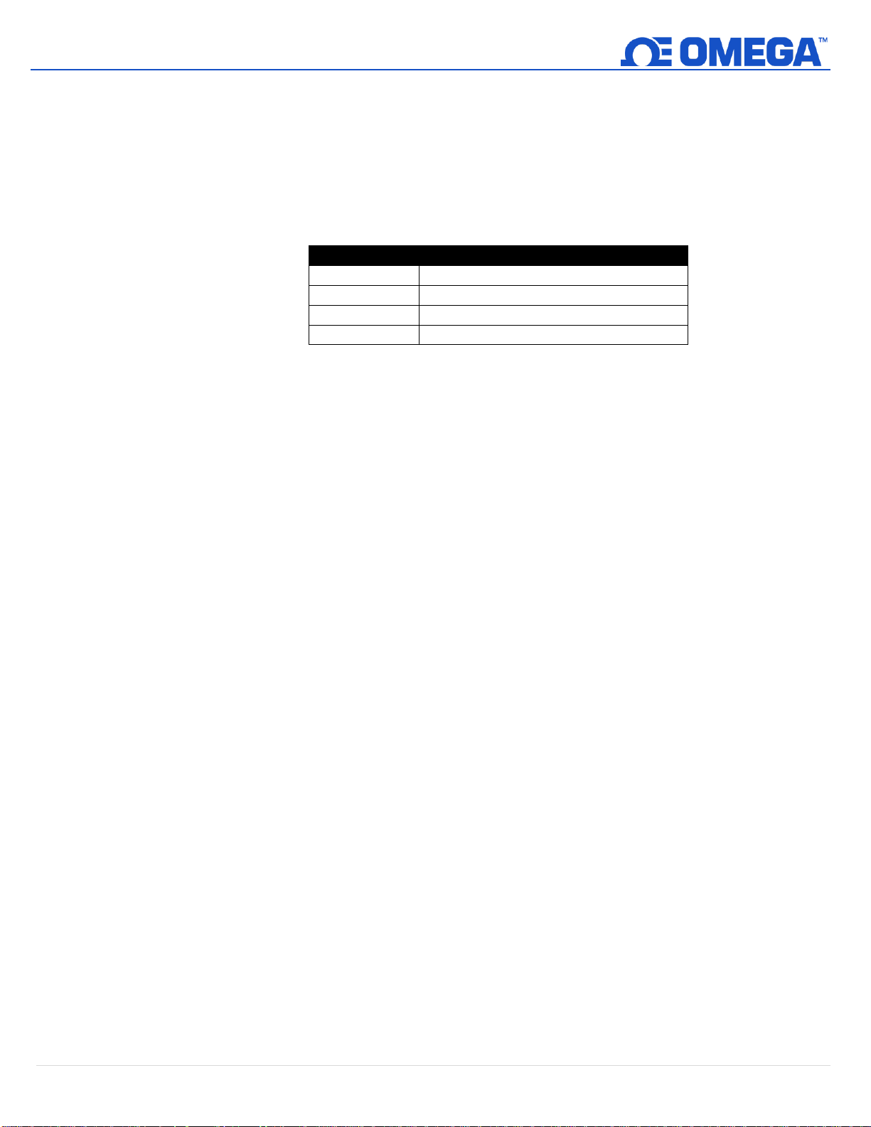
change the Material dropdown to the appropriate plastic pipe material according to the table below:
Type
Material
PVC
Polyvinyl Chloride
CPVC
Chlorinated Polyvinyl Chloride
PP
Polypropylene
PFA
Perfluoroalkoxy Alkanes
Step 2: To use pre-configured pipe wall thickness dimensions, select the appropriate pipe schedule from the
Schedule drop-down list.
Step 3: To configure your non-standard pipe thickness, go to the Parameters section and change the
Thickness (mm) to the appropriate wall thickness, entered in millimeters.
Step 4: The Pipe Diameter (OD mm) will be pre-configured for the actual pipe outer diameter, based on the
SKU that you ordered, but this value can be changed if used on other pipe diameters.
Step 5: Once you have completed configuring the HANI™ Clamp Temperature Sensor inputs, click Apply
Settings to finalize your changes.
Page 11
11 | H A N I ™
UNRESTRICTED
5.1.1 Calibration
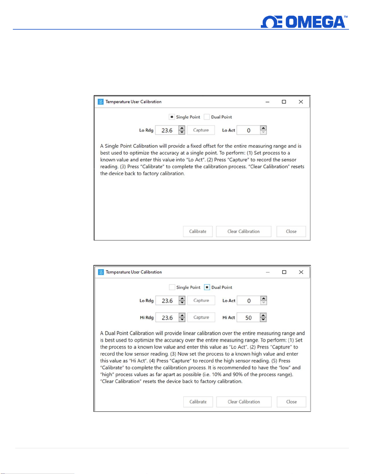
The HANI™ Clamp Temperature Sensor has a standard 2-point calibration from the factory, but sometimes,
to optimize the accuracy in the user’s application, a User Calibration is necessary. A Single-Point or Dual-
Point User Calibration can be performed through Omega’s SYNC configuration software. To perform a
successful calibration, the temperature inside the pipe must be known or measurable with an immersion
sensor. This immersion sensor temperature value will be used to calibrate the HANI™ Clamp Temperature
Sensor based on one of the two procedures below:
Figure 9: SYNC Configuration Software – Single Point Calibration
Figure 10: SYNC Configuration Software – Dual Point Calibration
Page 12
12 | H A N I ™
UNRESTRICTED
Low Actual:
The real low-temperature process value, as measured by the reference immersion
sensor in the process line. For Single-Point Calibrations, you may choose any
temperature in the sensor’s process range. For Dual-Point Calibrations, it is
recommended to choose a temperature on the low-end of the sensor’s process
range (i.e. 20°C).
Low Reading:
The low process value read by the HANI™ Clamp Temperature Sensor.
Capture:
The Capture button will take a live reading from the HANI™ Clamp Temperature
Sensor and input the value into the Low Reading or High Reading, as directed.
High Actual:
The real high-temperature process value, as measured by the reference
immersion sensor in the process line. Not applicable for Single-Point Calibrations.
For Dual-Point Calibrations, it is recommended to choose a temperature on the
high-end of the sensor’s process range (i.e. 80°C).
High Reading:
The high process value read by the HANI™ Clamp Temperature Sensor.
Calibrate:
The Calibrate button calculates and calibrates the new slope and offset based on
the Readings and Actuals entered above.
Clear Calibration:
This button will clear the previously entered User Calibration values and as a
result, returns the HANI™ Clamp Temperature Sensor to its factory calibration.
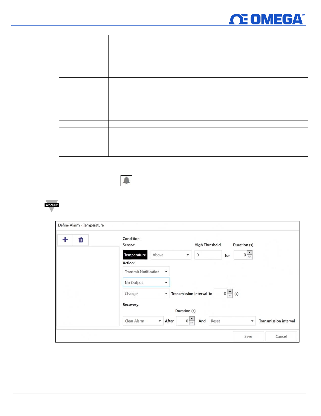
5.1.2 Setting Alarms
Alarms are set by clicking the icon in SYNC on the highlighted input signal found in the Inputs
configuration tab.
Note: Alarm Outputs are only available on Digital Output models currently; analog output products do
not support alarm outputs at this time but can still transmit notifications to the Omega Link Cloud.
Figure 11: SYNC Configuration Software – Setting Alarms
Configure the Condition that triggers the alarm by selecting an option from the drop down such as Above or
Below. The Threshold field(s) will change to display whatever is appropriate for the option chosen such as a
High Threshold for an Above condition or a Low Threshold for a Below condition. A Duration can be set for
the trigger as well where the condition must be met for a certain amount of time before the alarm flags.
Page 13
13 | H A N I ™
UNRESTRICTED
Under the Action menu, the option to transmit or not transmit a notification can be set. The option to
enable an output can also be set. The output chosen must not be currently used in a sensor mapping or
ON/OFF control module. The data transmission interval may also be changed upon triggering an alarm, e.g.
increase the rate of transmission if an excessive value is detected.
The Recovery menu allows the option to clear the alarm after a certain Duration once the trigger condition
is no longer met. The transmission interval can also be reset to the normal system setting once the alarm is
cleared.
To create a new alarm, click the plus icon and a new alarm will be added. To remove an alarm once it
is created, select the alarm in question on the left side of the alarm panel and click the delete icon .
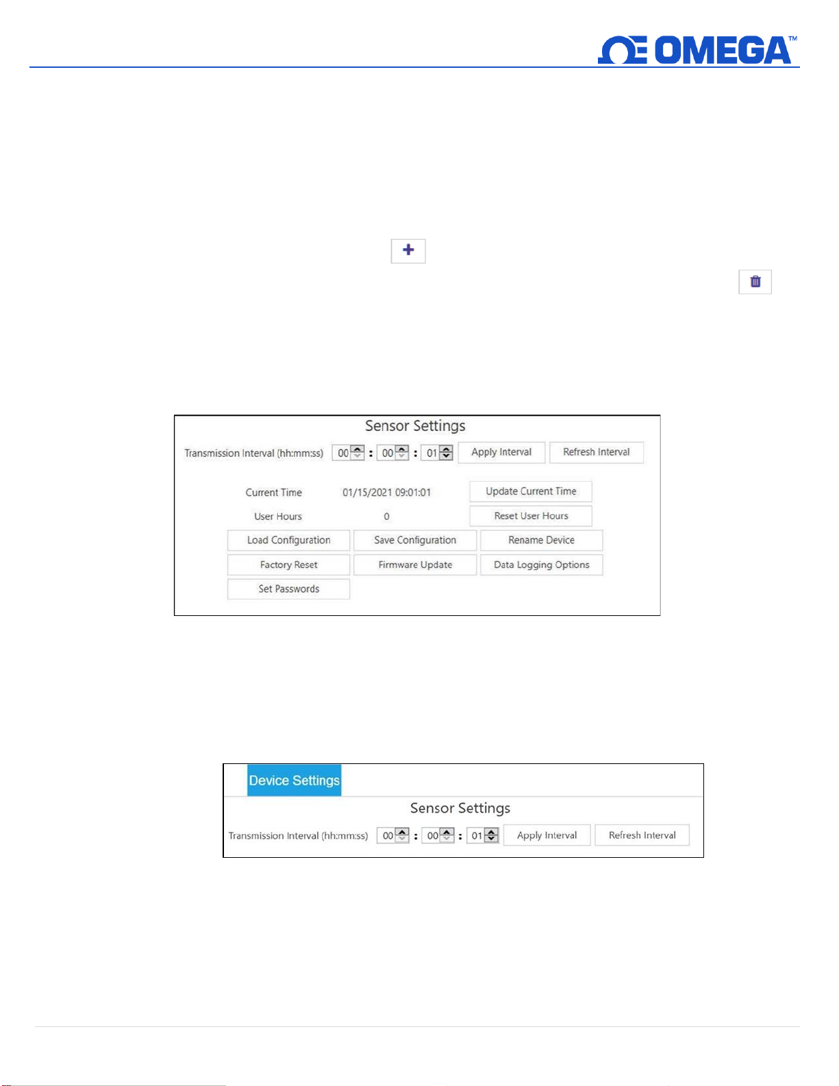
5.2 Configuring Device Settings
Omega’s SYNC configuration software can be used to configure the device settings of your HANI™ Clamp
Temperature Sensor. To configure your device settings, navigate to the Device Settings configuration tab of the
SYNC interface.
Figure 12: SYNC Configuration Software – Sensor Settings
5.2.1 Transmit Interval
The transmit interval can be adjusted by navigating to the Device Settings tab in the SYNC interface and will
appear beneath the Sensor Settings section. The Transmit Interval determines the time between readings for
the HANI™ Clamp Temperature Sensor. The transmit interval will also be reset to your minimum interval
based on your Omega Link Cloud account once your device is paired to the Omega Link Cloud.
Figure 13: SYNC Configuration Software – Transmit Interval
5.2.2 Setting/Changing Passwords
HANI™ Clamp Temperature Sensor data can be password protected through SYNC. Password protecting your
HANI™ Clamp Temperature Sensor prevents data in the device from being extracted without authorization.
If your Smart Probe is password-protected, the password must also be stored in the Omega Link Smart
Interface so it can transmit data to the Omega Link Cloud. To assign a password to your HANI™ Clamp
Temperature Sensor, follow these instructions:
Page 14
14 | H A N I ™
UNRESTRICTED
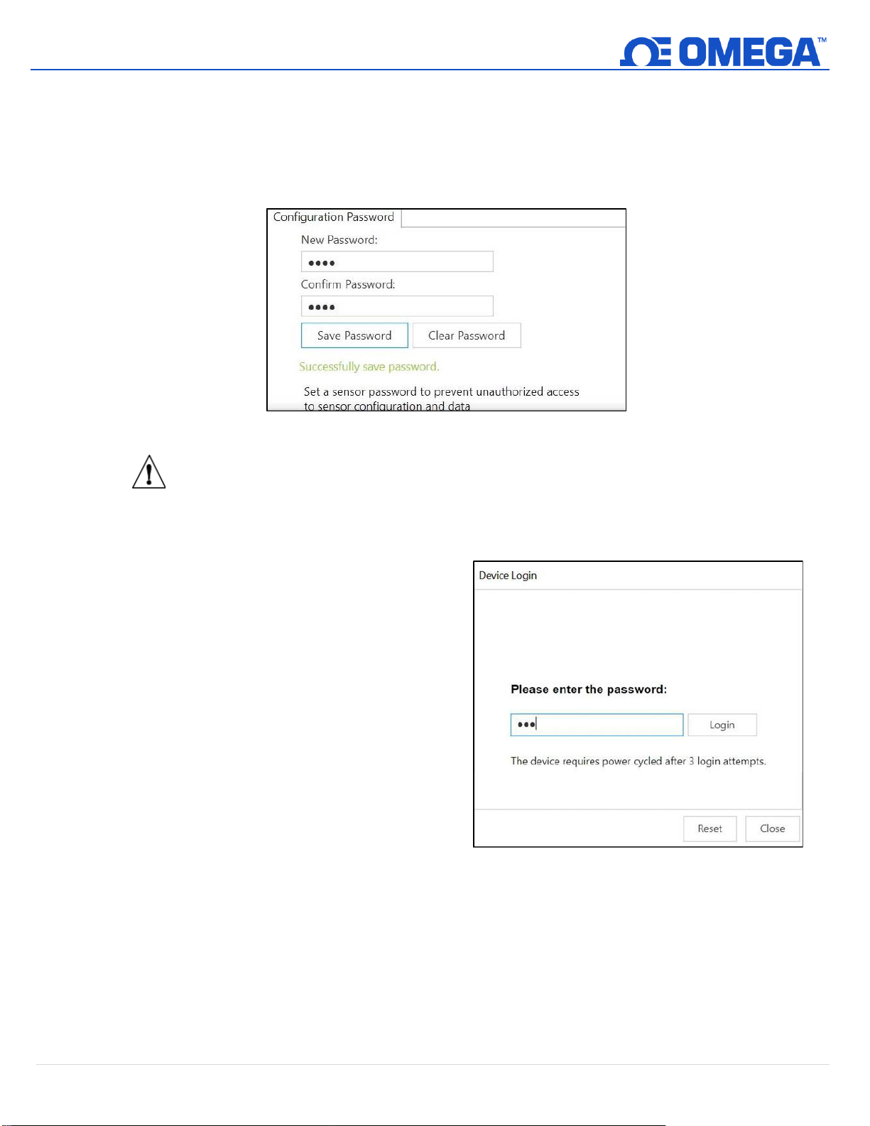
Step 1: Navigate to the Device Settings tab in the SYNC interface and click Set Passwords under the
Sensor Settings section.
Step 2: Create a Configuration Password. Upon saving your password, you will be prompted to update
the Interface Password as well to ensure your data is transmitted to the Omega Link Cloud.
Figure 14: SYNC Configuration Software – Password Update
Important: If the interface password does not match the configuration password, data from your
HANI™ Clamp Temperature Sensor will not be sent to the Omega Link Cloud.
5.2.2.1 Save Password
Password protects the SYNC configurable features of your HANI™ Clamp Temperature Sensor and saves
the newly entered password if it is successfully entered and confirmed in both text fields.
5.2.2.2 Clear Password
The Clear Password button removes the
password protection from the probe.
5.2.2.3 Login
Click the Login button after entering your
device password to access the configurable
features.
5.2.2.4 Reset
The Reset Password button deletes the
current password on the device. This will
cause all logged data to be erased.
After 3 failed login attempts, it is required to power cycle the
device before trying to login again.
Figure 15: SYNC Configuration Software – Device Login
Page 15
15 | H A N I ™
UNRESTRICTED
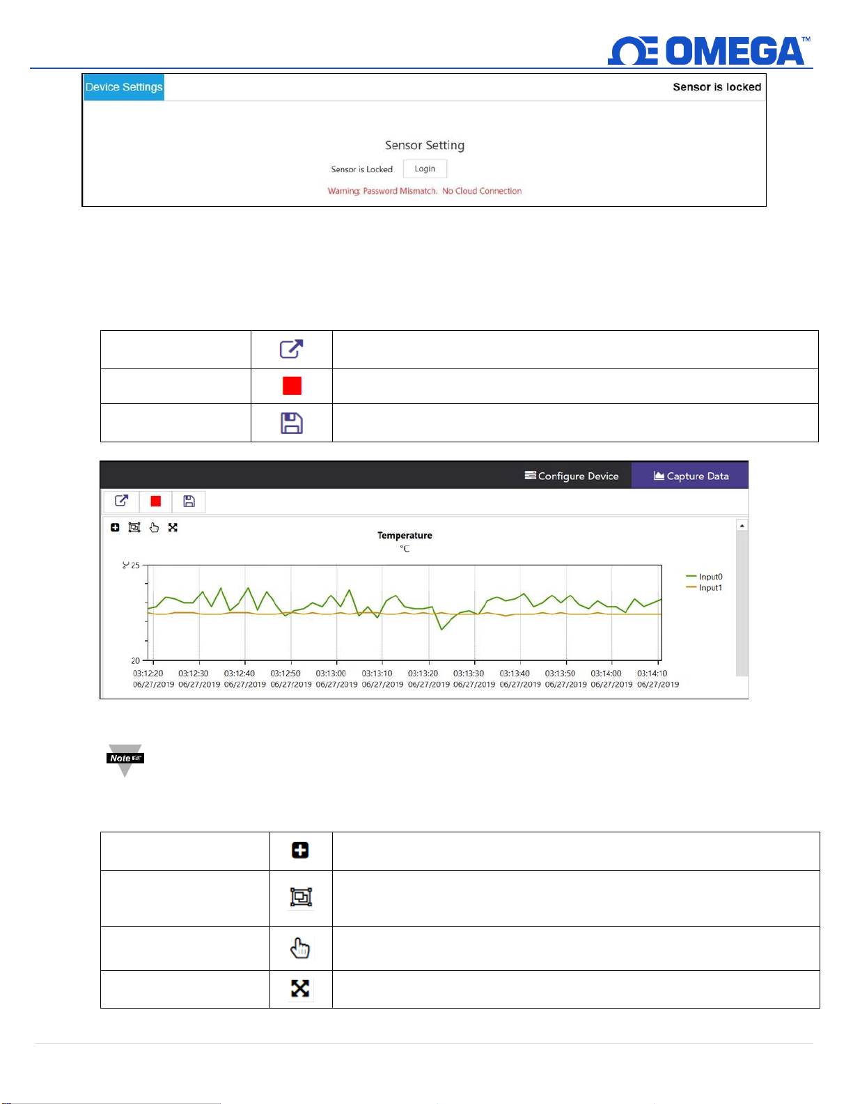
Figure 16: SYNC Configuration Software – Password Locked Device
5.3 Data Logging
The Capture Data interface provides a chart that displays real-time data from your connected HANI™ Clamp
Temperature Sensor devices. The Capture Data interface contains the following features:
Extract Data
Extracts data from the device data logger.
Start/Stop Recording
Toggles the real-time data displays to on/off.
Export Data to CSV
Gathers the data that has been recorded or extracted and saves it in a CSV
file.
Figure 17: SYNC Configuration Software – Data Logging
Note: Data will be reset if the user switches to the Configure Device interface. The SYNC Data Capture
feature is for short-term data logging.
SYNC provides four ways to navigate the Capture Data Interface:
Zoom by Rectangle
Allows the user to left-click and drag the mouse across the graphed data to
create a rectangle that will be zoomed in on.
Zoom by Middle Mouse
Wheel
Allows the user to zoom in and out of the graphed data using the middle
mouse wheel. This only applies to users who have a mouse with the
necessary mouse wheel feature.
Pan by Left Mouse
Button
Allows the user to left-click and drag on the graphed data to navigate in the
direction of the mouse.
Reset
Resets the graphed data to the original position.
Page 16
UNRESTRICTED
6. 4-20mA Loop-Powered Output
Scaling Maximum
(75 oC)
Scaling Minimum
(25 oC)
Maximum Value
(100 oC)
24 mA
20 mA
4 mA
0 mA
Fault High
(21.5 mA)
Fault Low
(3.8 mA)
Lowest Operating
Current (3.6 mA)
Minimum Value
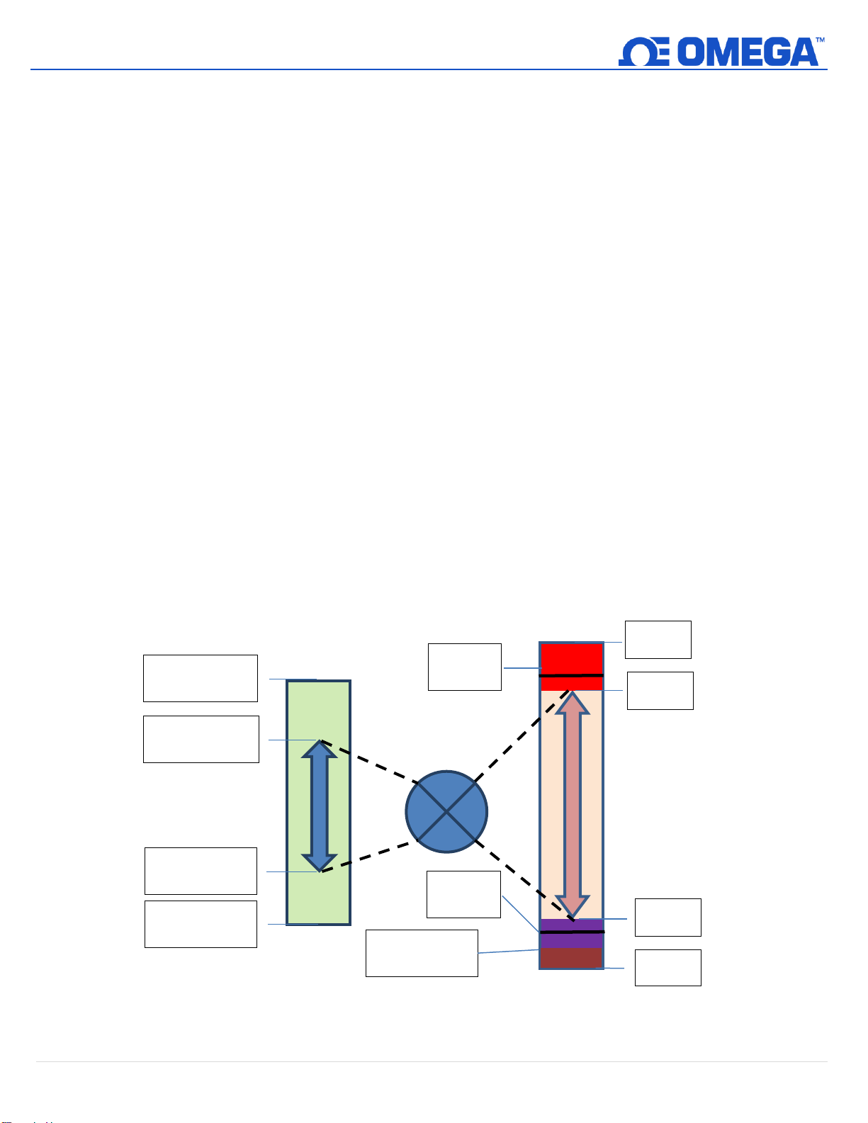
Devices configured for 4-20 mA Loop Power disable the DIO Inputs and the Digital Outputs. 4-20mA Outputs are
widely used due to several advantages’ over-voltage outputs:
• Higher noise immunity
• Ability to power the sensing device using the measurement current – provided total power is less than ~ 3.5mA
* minimum loop voltage
• Automatic wire break detection – if the signal wires are shorted the current will exceed the control system to
detect the fault
• Automatic wire short detection – if the signal wires are shorted the current will exceed the specified 20mA,
allowing the control system to detect the fault.
The HANI™ Clamp Temperature Sensor 4-20mA Loop Powered device requires a minimum loop voltage of 8.0 volts,
allowing the device to be powered using conventional 4-20mA control signals. The factory default configuration
connects the measured temperature to the 4-20mA output signal.
6.1 Sensor Mapping
The HANI™ Clamp Temperature Sensor defaults to mapping the measured Temperature to the 4-20mA output.
Two user-defined values (Scaling Minimum, Scaling Maximum) define the Temperature range that is mapped to
the 4-20mA. A measured value outside of the specified range results in an Over-Range or Under-Range condition.
A Factory Reset sets the Scaling Minimum to 0°C and the Scaling Maximum to 100°C.
If the Measured Value exceeds the user-defined Scaling Maximum an Over-Range condition exists and the 4-20mA
output may be configured to generate either a Fault High (21.5mA) current or a Fault Low (3.8mA) current. The
default setting is to generate a Fault High (21.5mA) current.
Similarly, if the measured value is less than the user-defined Scaling Minimum an Under-Range condition exists,
and the output may be configured to generate either a Fault High or Fault Low output. The default setting is to
generate a Fault Low (3.8mA) current.
(-20 oC)
A Loop Error occurs if the applied voltage of the 4-20mA loop drops below the specified minimum loop voltage and
the output will be driven to a Low Error level of ~ 3.8 mA.
16 | H A N I ™
Page 17
17 | H A N I ™
UNRESTRICTED
6.1.1 4-20 mA Outputs Sensor Mapping
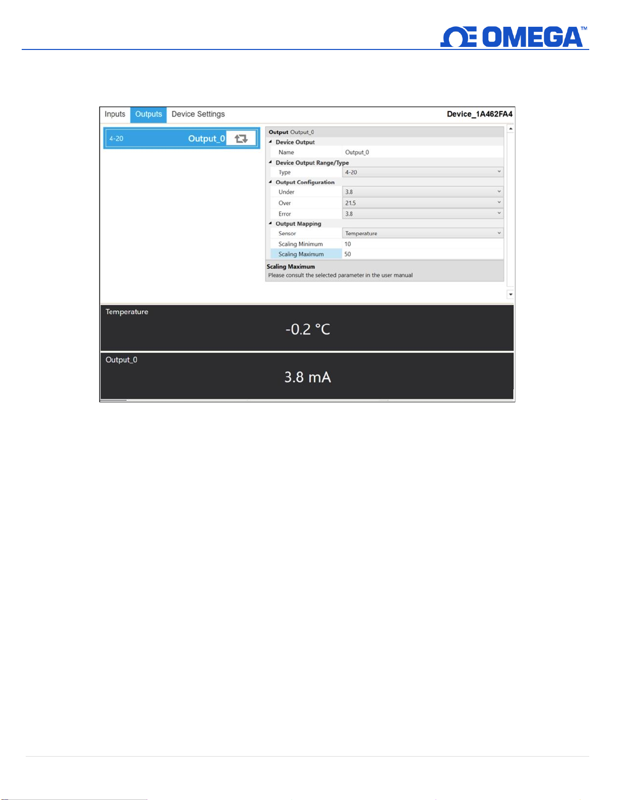
The HANI™ Clamp Temperature Sensor offers 4-20 mA output sensor mapping. Navigate to the Outputs
Configuration Tab on SYNC.
Figure 18: SYNC Configuration Software – 4-20 mA Output Sensor Mapping
Under the Output Configuration section, you can set the under/over and error conditions of the 4-20 mA
analog output.
Under:
Any temperature value below the Scaling Minimum will generate an Under fault value.
Over:
Any temperature value above the Scaling Maximum will generate an Over fault value.
Under the Output Mapping section, you can set the desired 4-20 mA analog output scaling range. The HANI
Clamp Temperature Sensor comes standard with a 0-100°C temperature scaling range.
Scaling Minimum:
Set the Scaling Minimum Temperature value that will result in a 4 mA output.
In this example, a temperature of 10°C will result in a 4 mA analog output.
Scaling Maximum:
Set the Scaling Maximum Temperature value that will result in a 20 mA output.
In this example, a temperature of 50°C will result in a 20 mA analog output.
Page 18
18 | H A N I ™
UNRESTRICTED
7. Pairing to an Omega Link Gateway
Refer to either the Wireless Pairing or Wired Pairing instructions to pair a HANI™ Clamp Temperature Sensor to an
Omega Link Gateway. Before continuing to the pairing instructions, ensure the following prerequisites are met:
• Ensure that the Omega Link Gateway has been properly setup, powered on, and is in close physical proximity.
• (For Wired pairing) Ensure the user has access to a PC and the internal Gateway UI (refer to the Omega Link
Gateway manual for instructions on how to access the internal Gateway UI).
7.1 Wireless Pairing
Pairing a wireless Smart Interface (IF-006) and attached HANI™ Clamp Temperature Sensor is made easy with a
one-button pairing system between the IF-006 and the Omega Link Gateway.
Step 1: When the HANI™ Clamp Temperature Sensor and relevant accessories have been securely connected to
the IF-006, push the pairing button once on the IF-006. The LED status indicator will blink green indicating
the device is in Pairing Mode.
Step 2: Quickly push the pairing button on the Omega Link Gateway. The LED on the Gateway will blink green
indicating the Gateway is in Pairing Mode.
When the IF-006 has been successfully paired to the Omega Link Gateway, the LED will stop blinking on both
devices. Readings for the newly added sensor will then appear on the Omega Link Cloud or Omega Enterprise
Gateway interface associated with the registered Gateway.
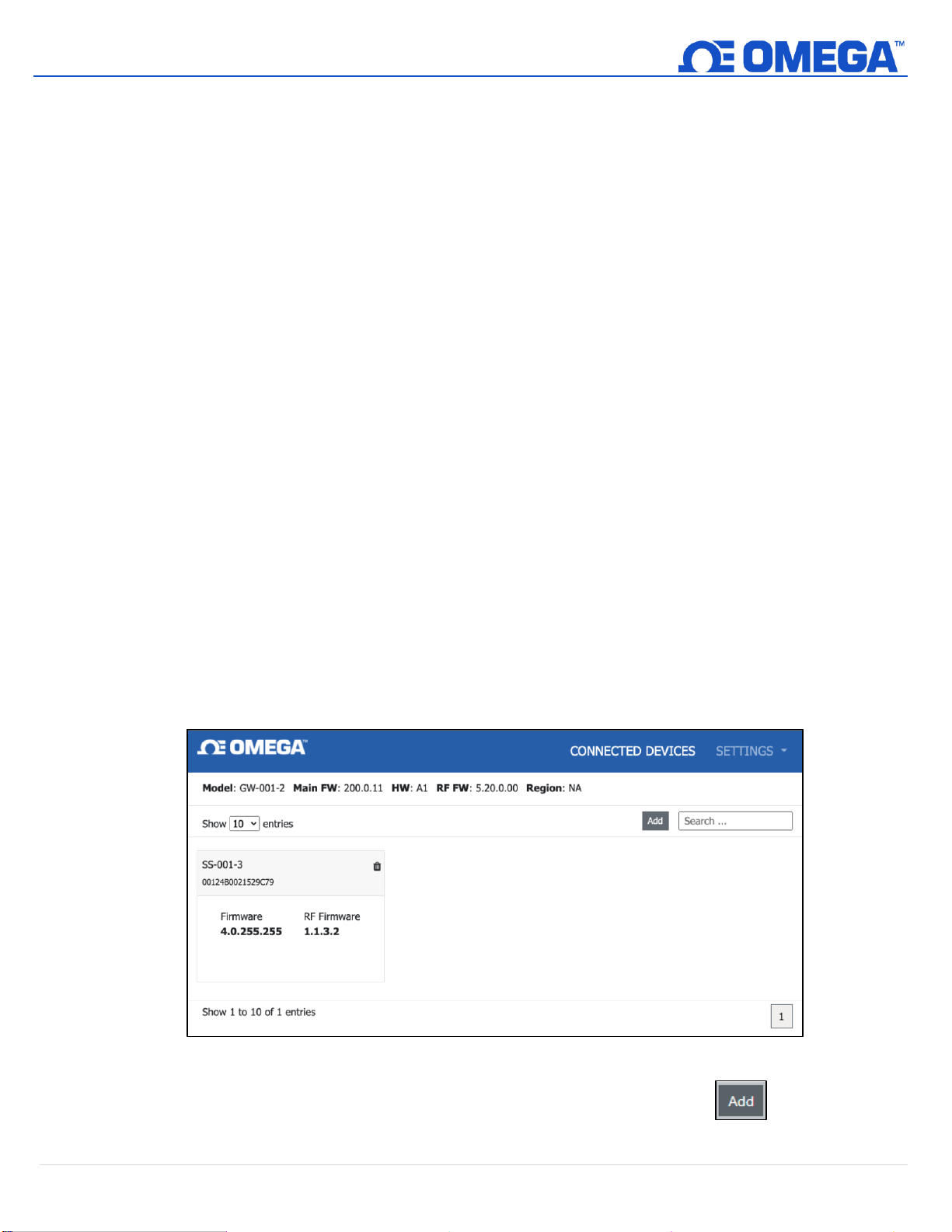
7.2 Wired Pairing
A wired HANI™ Clamp Temperature Sensor connected directly to an Omega Link Gateway with an IF-001 cable will
need to be added to the Gateway Internal User Interface. See the Omega Link Gateway User’s Manual for more
information. The Connected Devices tab is the default page shown once the user has signed in to the internal
gateway UI. From here, devices can be added to the gateway to have them appear in a registered Omega Link
Cloud or Omega Enterprise Gateway account.
Figure 19: Gateway Internal User Interface
To add a device to your gateway from the internal gateway web UI, begin by clicking the button at the top
right of the web page. Fill out the Add Device menu with the parameters of the Smart Probe connection.
Page 19
UNRESTRICTED
8. Specifications
INPUT POWER
Voltage: 8VDC – 28 V
Max Loop Resistance: R
ANALOG OUTPUT
Current: 4-20 mA
User scalable analog output, default scaling 0-100°C
PROCESS PARAMETERS
Process Medium: Water, water-based fluids (others upon request)
Pipe Materials: PVC, CPVC, PP, PFA (others upon request)
Nominal Pipe Size:
Industrial: 1”, 2” nominal (others upon request)
Process Temperature Range: -20 to 100°C liquid
Caution: It is important to know the pipe material’s temperature limit. The HANI™ sensor can measure up to
100°C, but some pipe materials have much lower temperature limits.
PERFORMANCE
Accuracy with Fluid Flowing:
Industrial: ±1.5°C from factory and improved accuracy is possible with in-situation 1 or 2-point calibration
Response Time (τ63): 30 seconds
Response Time (τ90): 60 seconds
(Loop Powered)
DC
(Ω) = (V
MAX
- 8V)/0.024 A
SUPPLY
ENVIRONMENTAL
Ambient Operating Temperature: 0 to 40°C (32 to 104°F)
Rating: IP67 when mated
MECHANICAL
Dimensions: 60.3mm W x 64.31mm L x 51.54mm H (2.38” W x 2.53” L x 2.03” H)
Materials: PA12, silicone rubber, nickel-plated brass, stainless steel
GENERAL
Agency Approvals: CE, UKCA, EMC 2014/30/EU, LVD 2014/35/EU class II product, (low voltage 8 to 28VDC)
19 | H A N I ™
Page 20
20 | H A N I ™
UNRESTRICTED
9. Appendix: HANI™ Clamp Temperature Sensor Input Interface
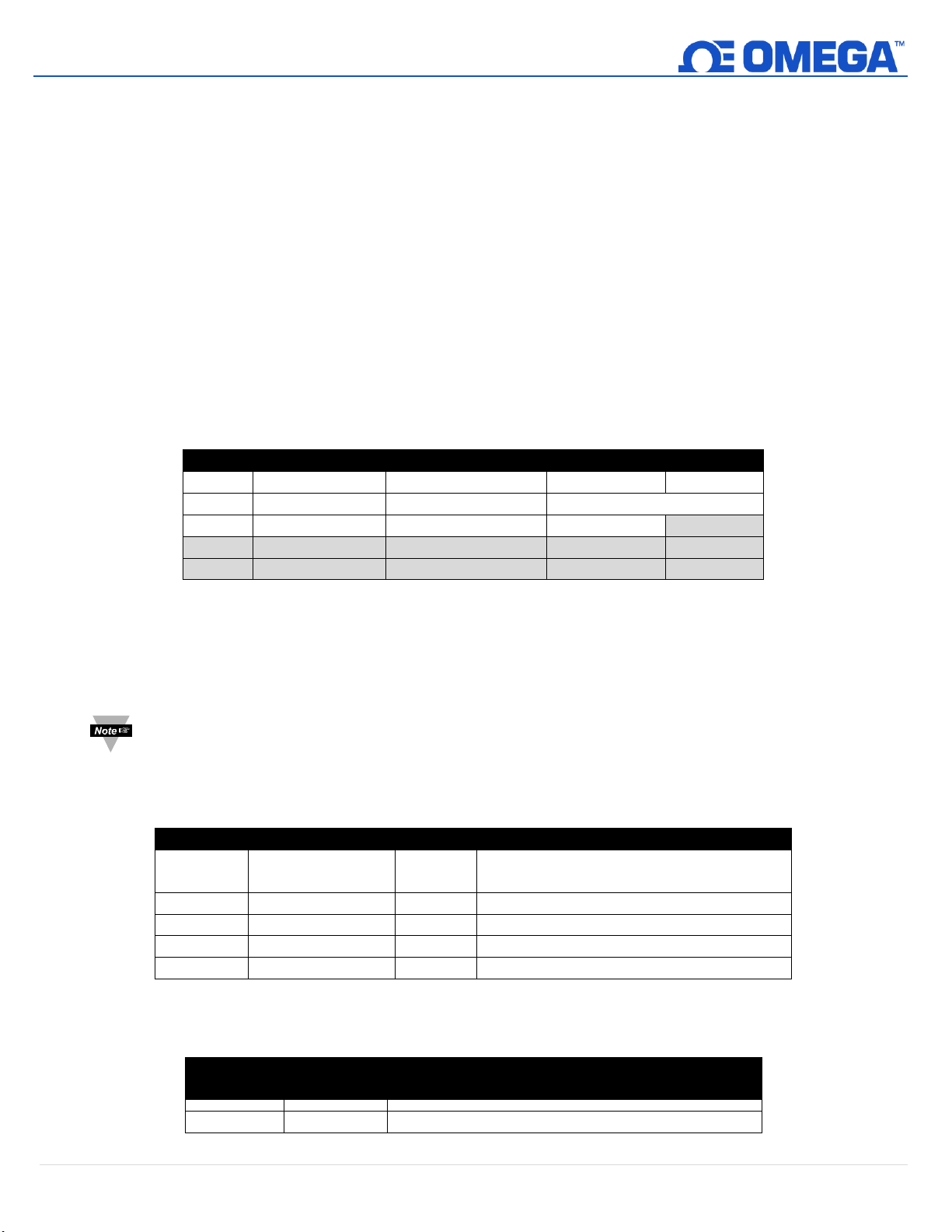
9.1 Register Base Addresses
Smart Probe devices share a common platform architecture that provides extensive monitoring and control
capabilities through a set of platform generic registers. These registers may be accessed using I2C based
commands directly to the Smart Probe devices or through a set of Modbus-based registers when using Omega
Interface devices.
When powered on or after a device reset each Smart Sensor-based device will enumerate 1 or more sensor
instances which are described by the device-specific Sensor Descriptors which include configuration options,
measurement type, and units of measure for the corresponding sensor values. Additional sensor information is
provided in sensor-specific IPSO object descriptions which include extended measurement type, precision and
tracking of minimum/maximum readings.
Each enumerated Sensor has a Descriptor Base address location and a Sensor IPSO / Configuration structure
address location based on the sensor mix selected.
Sensor
Descriptor Base
IPSO/Configuration
Enumerated Sensor Mix
Digital Output
4-20 mA
0
0x0060 (0xf030)
0x08a8 (0xf454)
Clamp-on Temperature
1
0x0068 (0xf034)
0x09a8 (0xf4d4)
DIO
2
0x0070 (0xf038)
0x0aa8 (0xf554)
3
0x0078 (0xf03c)
0x0ba8 (0xf5d4)
9.2 HANI™ Clamp Temperature Sensor Temperature Input Interface
The HANI™ Clamp Temperature Sensor Input interface provides a reading of the calculated temperature based on
the measured heat flux and temperature values.
Note: The HANI™ Clamp Temperature Sensor products will use a predefined configuration but will require
some customization based on the specific installation. Configuration options will be made available to the
end-user.
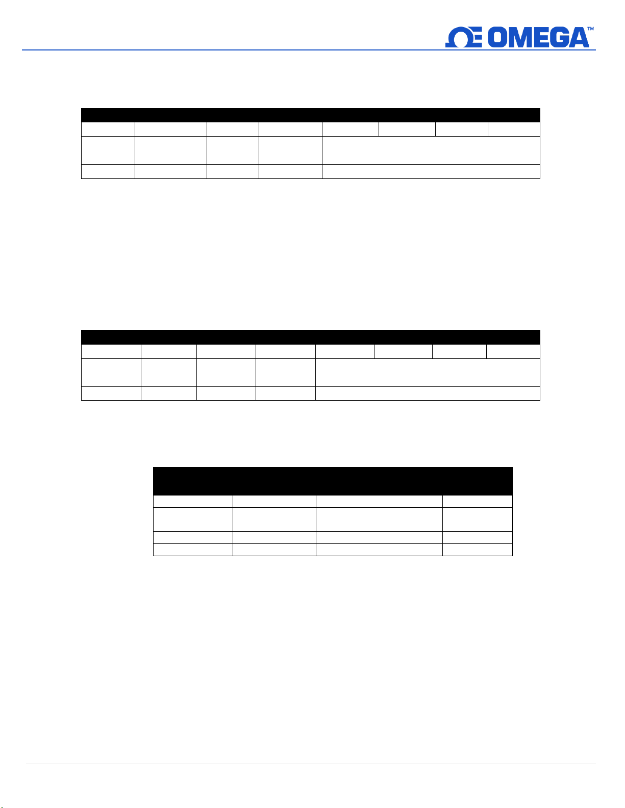
9.2.1 Sensor Input Descriptor
Offset
Name
Value
Description
0x00
Measurement
Type
0x37
Temperature (°C)
0x01
Data Type/Format
0x06
Float
0x02
Configuration
0x4?
Determines Material Type
0x03
Sensor Device
0x??
Determines connection type
0x04..0x08
UOMR
“°C”
Units of measure
9.2.1.1 Sensor Measurement Type
The temperature interface provides a measurement of Temperature in °C.
Sensor
Type
SI Derived
Units
Measurement
0x37
°C
Temperature
Page 21
21 | H A N I ™
UNRESTRICTED
9.2.1.2 Sensor Input Data Type/Format
The HANI™ Clamp Temperature Sensor supports extended configuration and provides factory
calibration. All data values are returned as 32-bit floating-point values.
HANI™ Clamp Temperature Sensor Input Data Type/Format
7 6 5 4 3 2 1
0
Smart
Sensor
Writeable
Factory
Calibrate
Reserved
Data Type
0 0 0
0
0x06 == FLOAT
9.2.1.2.1 Data Type
The 4-bit Data Type field determines the type of data of the specific sensor.
9.2.1.2.2 Factory Calibrate
Factory calibration is available for the HANI™ Clamp Temperature Sensor process inputs. Clearing
this bit will disable the factory calibration values.
9.2.1.2.3 Writeable
The writeable bit is cleared, indicating that the sensor values may not be overwritten.
9.2.1.3 Sensor Configuration Byte
HANI™ Clamp Temperature Sensor Configuration Byte
7 6 5 4 3 2 1
0
Available
Assigned
Apply
Scaling
Lock
Sensor Range / Type
0 * ?
?
Material (see below)
9.2.1.3.1 Sensor Range / Type
The Range / Type field determines the type of pipe material, which determines the thermal
conductivity.
Range / Type
Material
DESCRIPTION
Conductivity
(W/m-K)
0x00
PVC
Polyvinyl Chloride
0.190
0x01
CPVC
Chlorinated Polyvinyl
Chloride
0.137
0x02
PP
Polypropylene
0.125
0x03
PFA
Perfluoroalkoxy Alkanes
0.209
9.2.1.3.2 Lock
If set, the user-specified units of measure string (4 character maximum) will be used in place of the
default units of measure.
9.2.1.3.3 Apply Scaling
If set, the user-defined Offset and Gain values will be used to adjust the sensor reading:
Result = (Raw Reading * Gain) + Offset
9.2.1.3.4 Assigned
The Assigned bit will always read as 0.
9.2.1.3.5 Available
The Available bit will always read as 0.
Page 22
UNRESTRICTED
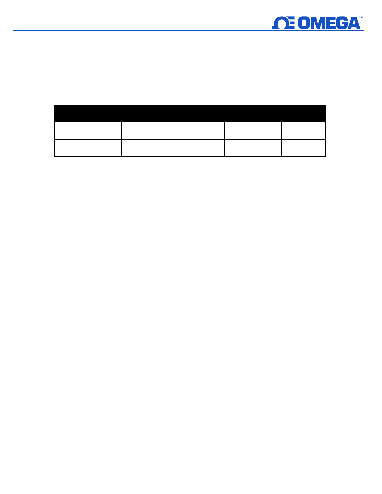
9.2.1.4 Sensor Device Byte
Parameter
I2C
Register
Modbus
Register
Name
Range
Step
Size
Factory
Reset
Description
0
0x08c0
0xf460
Diameter
25.4 –
76.2
0.1
38.1
Diameter in
mm
1
0x08d0
0xf468
Thickness
1.0 –
10.0
0.1
1.7
Thickness in
mm
The HANI™ Clamp Temperature Sensor device byte is not used.
9.2.2 Sensor Temperature Parameters
The HANI™ Clamp Temperature Sensor provides 2 Sensor Parameters that may be updated based on the
specific installation.
The HANI™ Clamp Temperature Sensor Temperature parameters are accessible when the device is in the
normal operating mode (see IPSO Trigger Function).
9.2.2.1 Diameter
The Diameter is used in the calculation of the temperature and is a factor of the specific installation.
9.2.2.2 Thickness
The Thickness is used in the calculation of the temperature and is a factor of the specific installation.
22 | H A N I ™
Page 23
UNRESTRICTED
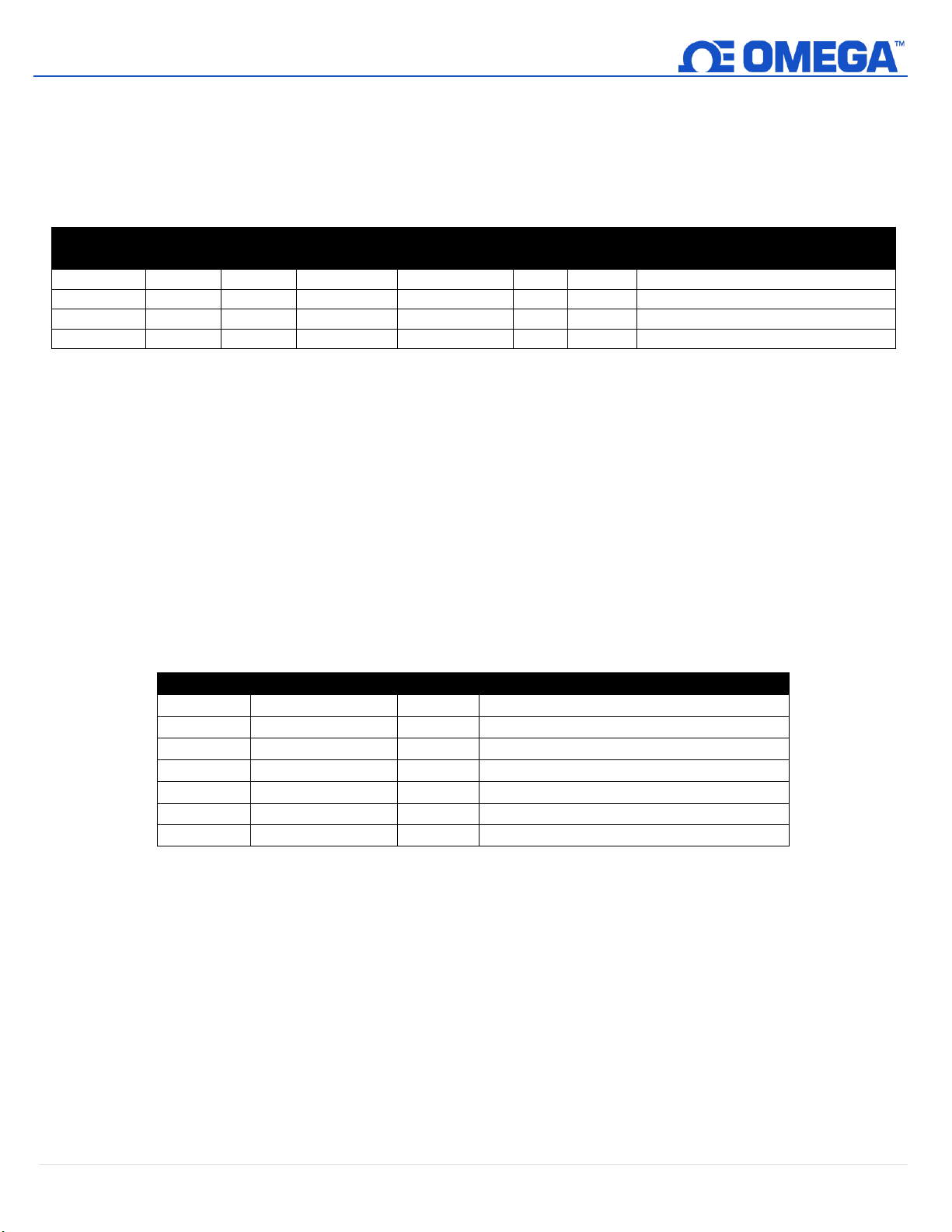
9.2.3 Sensor User Calibration Parameters
Parameter
I2C
Register
Modbus
Register
Name
Range
Step
Size
Factory
Reset
Description
0
0x08c0
0xf460
Low Reading
0.0 – 100.0
0.1
0.0
Value being read by HANI™ sensor
1
0x08d0
0xf468
Low Actual
0.0 – 100.0
0.1
0.0
Actual measured value.
2
0x08e0
0xf470
High Reading
0.0 – 100.0
0.1
100.0
Value being read by HANI™ sensor
3
0x08f0
0xf478
High Actual
0.0 – 100.0
0.1
100.0
Actual measured value.
Offset
Name
Value
Description
0xa8
Sensor Type
3303
Temperature (°C)
0xaa
Precision
1
Provides reading of xxx.x
0xac
Sensor Trigger
??
(see below)
0xb0
Min Measured
??
Minimum reading since the last reset
0xb4
Max Measured
??
Maximum reading since the last reset
0xb8
Min Range
0
Minimum temperature
0xbc
Max Range
100
Maximum temperature
The HANI™ Clamp Temperature Sensor provides a single or dual-point User Calibration.
The HANI™ Clamp Temperature Sensor parameters are accessible when the device is in the Calibration
mode (see IPSO Trigger Function). The Calibration Value is calculated internally during the User Calibration
sequence and is not externally accessible.
9.2.3.1 Low Reading
The temperature value being read by the HANI sensor.
9.2.3.2 Low Actual
The actual low temperature as measured by an external, independent sensor.
9.2.3.3 High Reading
The temperature value being read by the HANI sensor.
9.2.3.4 High Actual
The actual high temperature as measured by an external, independent sensor.
9.2.4 Sensor IPSO Definition
The HANI™ Clamp Temperature Sensor IPSO definition provides signal range, measured min/max values,
IPSO object type information. The Range information is Temperature Type dependent.
9.2.4.1 Precision
The measured temperature value is rounded to provide ±0.1 degree resolution.
23 | H A N I ™
Page 24
UNRESTRICTED
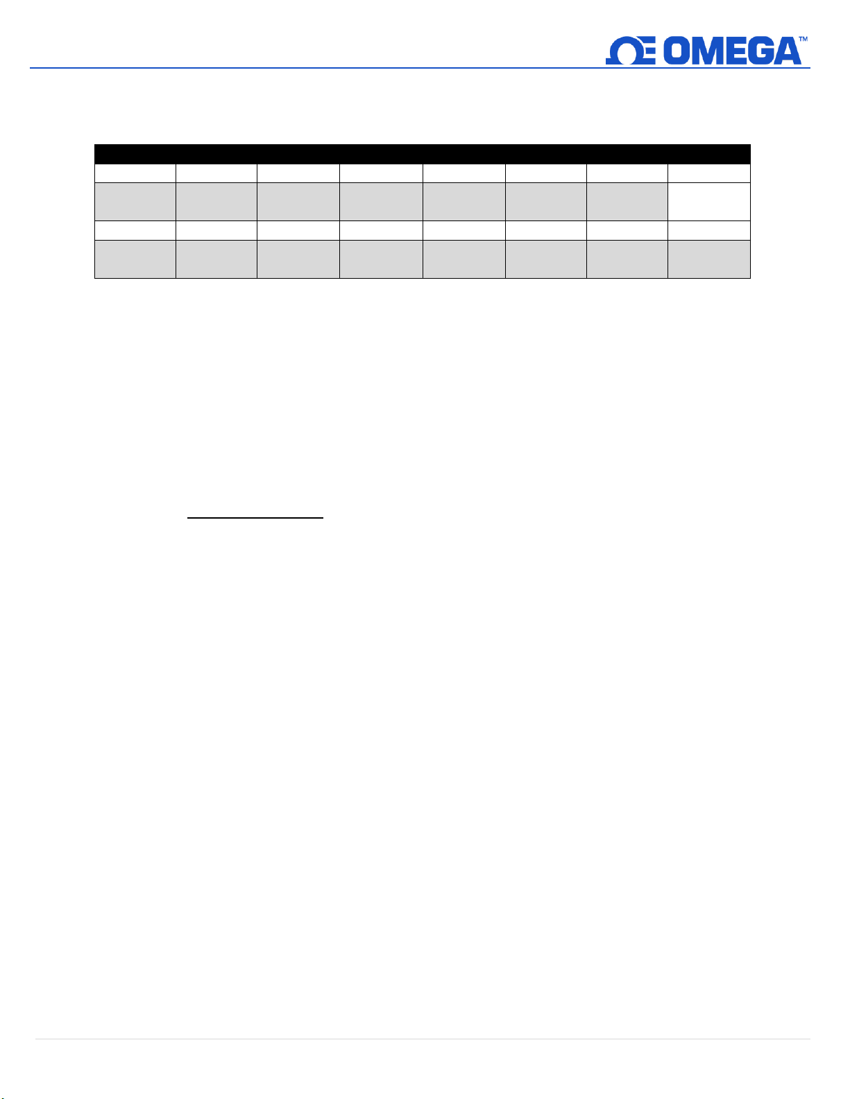
9.2.4.2 Sensor Trigger
Sensor Trigger
7 6 5 4 3 2 1
0
0 0 0 0 0 0 0
Reset
Min/Max
15
14
13
12
11
10 9 8
0
0
Calibration
Reset
Calibration
Status
Calibration
Mode
Capture
High
Capture
Low
Calibration
Start
The Sensor Trigger function is used to reset the IPSO min/max values as well as controlling the
Calibration process.
Setting the Reset Min/Max bit to 1 will reset the Min/Max values recorded by the IPSO process.
9.2.4.2.1 User Calibration Sequence
User Calibration allows the user to adjust out small errors by providing an offset (single-point
calibration) or offset and gain (dual point calibration) to the measured temperature value. The
following sequence may be used to set the correction value:
1. Write 0x0800 to the Trigger Function register (Calibration Mode bit set). This forces the
device into Calibration Mode and the Sensor Parameter register access is replaced with the
Sensor Calibration register access.
Dual Point Calibration
2. Apply a known fluid temperature near the lower end of the expected temperature range and
enter it into the Low Actual register (0x08c4 / 0xf462).
3. Record the value being measured by the HANI sensor and enter it into the Low Reading
register (0x08c0 / 0xf460). This process can be simplified by writing a value of 0x0a00 to the
Trigger Function register which will cause the HANI sensor to capture the current reading and
save it as the Low Reading Value.
4. Apply a known fluid temperature near the higher end of the expected temperature range and
enter it into the High Actual register (0x08cc / 0xf466).
5. Record the value being measured by the HANI sensor and enter it into the High Reading
register (0x08c8 / 0xf464). This process can be simplified by writing a value of 0x0c00 to the
Trigger Function register which will cause the HANI sensor to capture the current reading and
save it as the High Reading Value.
6. Write 0x0900 to the Trigger Function register (Calibration Mode and Calibration Start).
Internally the device will set the Calibration Status bit and calculate the Gain and Offset
linearization values. When the calibration calculation is complete the Calibration Status bit is
cleared.
7. Write 0x0000 to the Trigger Function register to return the device to the normal operating
mode.
24 | H A N I ™
Page 25
UNRESTRICTED
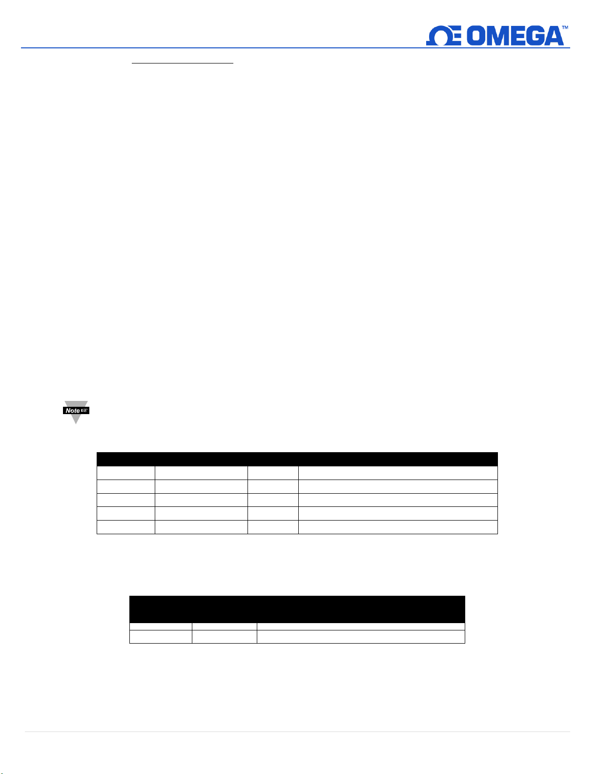
9.3 DIO Interface
Offset
Name
Value
Description
0x00
Sensor Type
0x18
Digital Type (Bit mapped)
0x01
Data Type/Format
0x46
Configurable, Float type
0x02
Configuration
0x23
Scaling applied, Bits 0 and 1 enabled
0x03
Sensor Device
0x0f
DIN bits enabled / inverted
0x04
UOMR
“DIN”
Units of measure
Sensor
Type
SI Derived
Units
Measurement
0x18
DIN
Bit mapped digital inputs
Single Point Calibration
8. Apply a known fluid temperature near the center of the expected temperature range and
enter it into the Low Actual register (0x08c4 / 0xf462).
9. Record the value being measured by the HANI sensor and enter it into the Low Reading
register (0x08c0 / 0xf460). This process can be simplified by writing a value of 0x0a00 to the
Trigger Function register which will cause the HANI sensor to capture the current reading and
save it as the Low Reading Value.
10. Write the same value from Step 8 into the High Actual register (0x08cc / 0xf466).
11. Write 0x0900 to the Trigger Function register (Calibration Mode and Calibration Start).
Internally the device will set the Calibration Status bit and calculate the Offset value. When
the calibration calculation is complete the Calibration Status bit is cleared.
Write 0x0000 to the Trigger Function register to return the device to the normal operating mode.
The Correction value may be reset to zero by writing 0x2800 (Calibration Reset and Calibration
Mode) to the Trigger register.
The Digital output option supports a DIO Interface that provides 2 digital inputs that are hardwired to the Digital
outputs. These may be used to detect the state of external switches (output off) or to monitor the state of the
outputs.
Note: The DIO is not available for units configured with 4-20 mA outputs.
9.3.1 DIO Descriptor
9.3.1.1 DIO Sensor Type
The interface provides a bit mapped input of the 2 digital signal lines.
25 | H A N I ™
Page 26
UNRESTRICTED
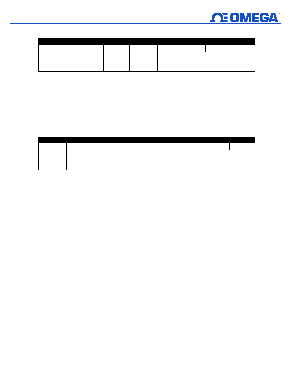
9.3.1.2 DIO Data Type/Format
DIO Data Type/Format
7 6 5 4 3 2 1
0
Smart
Sensor
Writeable
Factory
Calibrate
reserved
Data Type
0 0 0
0
6 == Floating point
DIO Input Configuration
7 6 5 4 3 2 1
0
Available
Assigned
Apply
Scaling
Lock
Sub Channel Selection
0 0 1
?
0x03 == bits 0 and 1
9.3.1.2.1 Data Type
The 4-bit Data Type field determines the type of data of the specific sensor.
9.3.1.2.2 Factory Calibrate
The Factory Calibrate bit is not used for DIO types.
9.3.1.2.3 Writeable
This indicates that the sensor value may be overwritten. Not used on DIO inputs.
9.3.1.3 DIO Input Configuration
9.3.1.3.1 Lock
If set, the user-specified units of measure string (4 character maximum) will be used in place of the
default DIN.
9.3.1.3.2 Apply Scaling
If set, the user-defined Offset and Gain values will be used to adjust the sensor reading:
9.3.1.3.3 Assigned
The Assigned bit will always read as 0.
9.3.1.3.4 Available
The Available bit will always read as 0.
Result = (Raw Reading * Gain) + Offset
26 | H A N I ™
Page 27
UNRESTRICTED
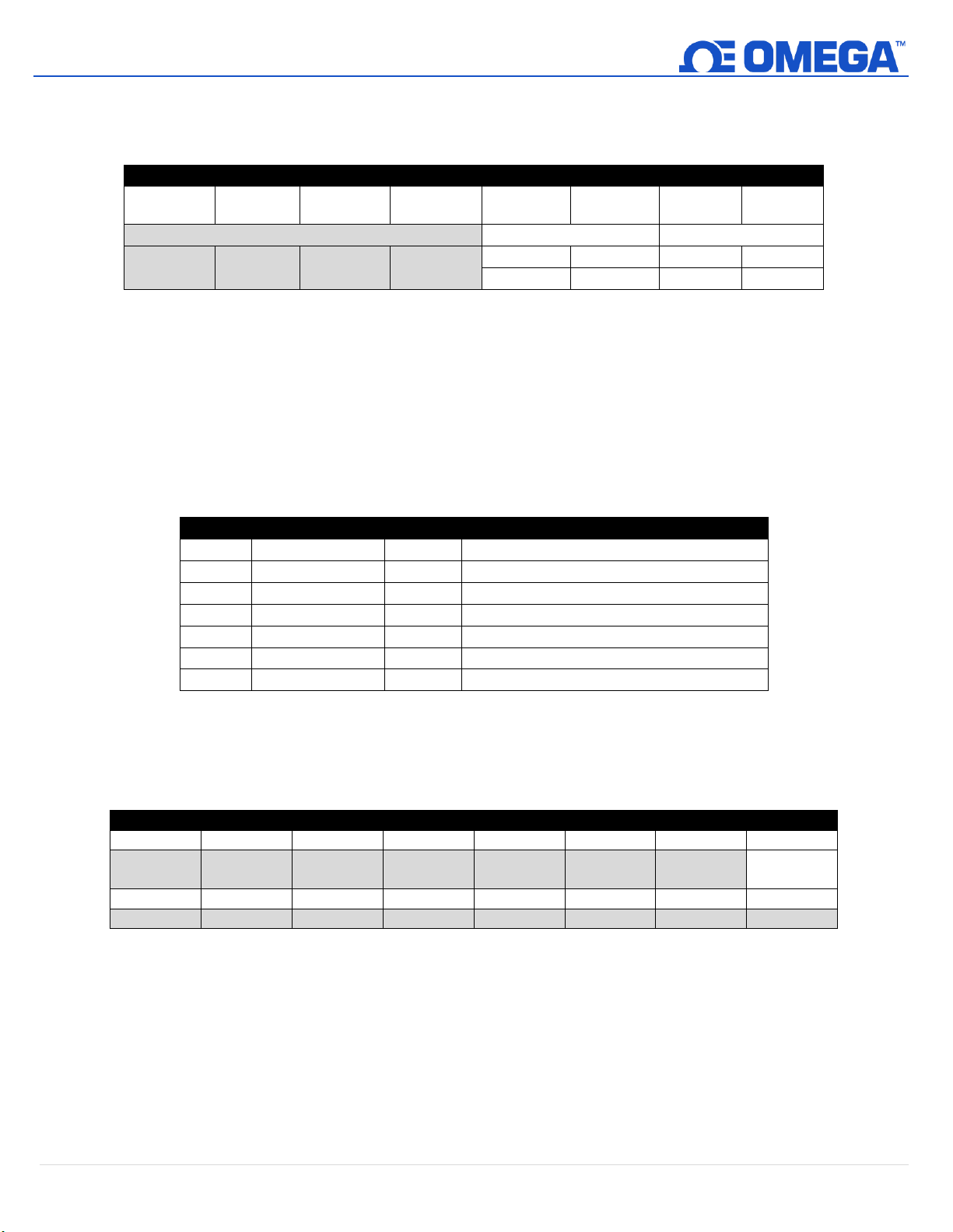
9.3.1.4 DIO Device Configuration
DIO Device Configuration
7 6 5 4 3 2 1
0
Reserved
DIN 1
DIN 0
0 0 0
0
ENABLE
INVERT
ENABLE
INVERT 1 1 1 1
Offset
Name
Value
Description
0xa8
Sensor Type
3349
Bit Mapped Digital
0xaa
Precision
0
Provides reading of xxx
0xac
Sensor Trigger
??
Write 0x0001 force reset of min / max
0xb0
Min Measured
??
Minimum reading since the last reset
0xb4
Max Measured
??
Maximum reading since the last reset
0xb8
Min Range
0
Minimum reading
0xbc
Max Range
3
Maximum reading
Sensor Trigger Function
7 6 5 4 3 2 1
0
0 0 0 0 0 0 0
Reset
Min/Max
15
14
13
12
11
10 9 8 0 0 0 0 0 0 0 0
The DIO Device Configuration allows enabling each of the 2 input bits and selecting whether the input is
active HIGH (reads as 1 when input is not grounded) or active LOW (reads as 1 when input is grounded).
9.3.1.4.1 Invert
If the Invert bit is set the input is active LOW.
9.3.1.4.2 Enable
If the Enable bit is set the input is enabled.
9.3.2 DIO IPSO Definition
The DIO input IPSO definition provides signal range, measured min/max values, IPSO object type
information.
9.3.2.1 Sensor Trigger Function
The Sensor Trigger function is used to reset the IPSO min/max values as well as controlling the
Calibration process.
Setting the Reset Min/Max bit to 1 will reset the Min/Max values recorded by the IPSO process.
No User Calibration process is supported on the DIO inputs and all Configuration bits should be written
as 0.
27 | H A N I ™
Page 28
UNRESTRICTED
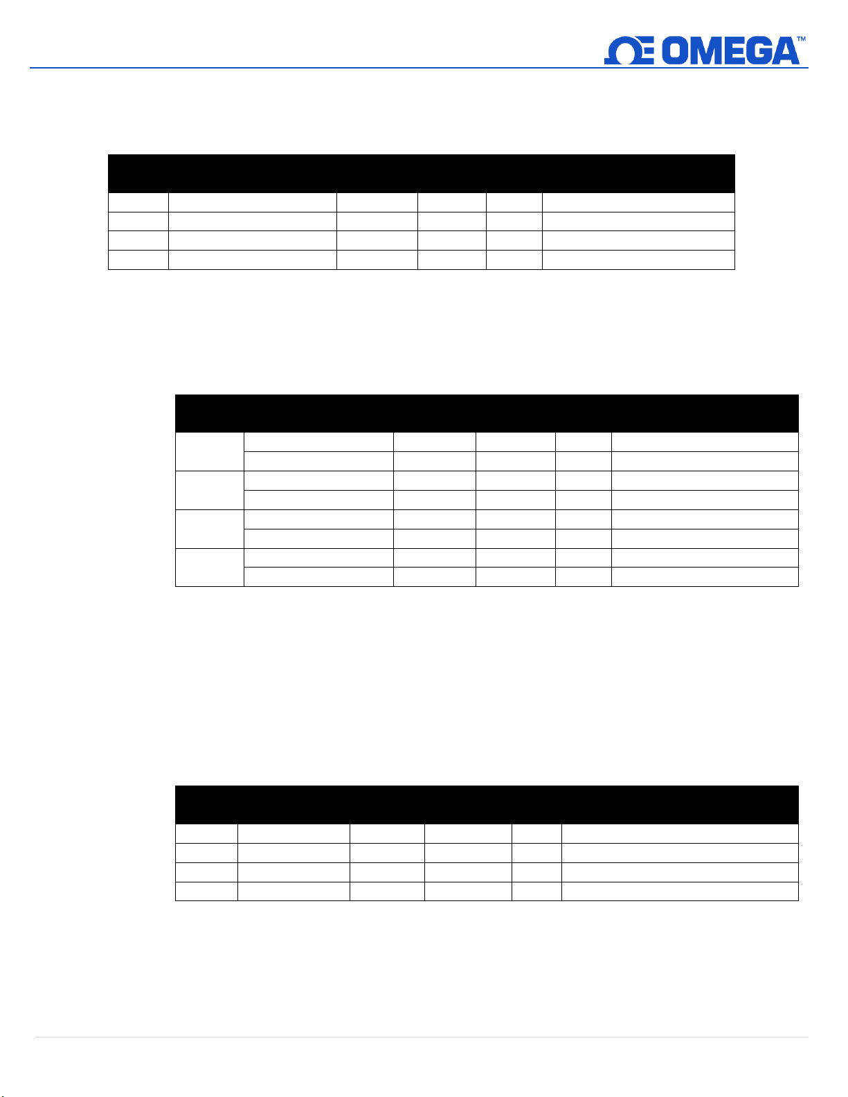
9.4 Output Configuration Registers
Output
Name
Modbus
Address
I2C
Address
Size
Typical Description
0
Output 0 Descriptor
0xf09a
0x0134
uint16
PWM 0 or 4-20 mA
1
Output 1 Descriptor
0xf09b
0x0136
uint16
PWM 1 (see below)
2
Output 2 Descriptor
0xf09c
0x0138
uint16
Phantom (non-configurable)
3
Output 3 Descriptor
0xf09d
0x013a
uint16
Phantom (non-configurable)
Sensor
Name
Modbus
Address
I2C
Address
Size
Description
0
Output 0 Low Scale
0xf1f0
0x03e0
float
Sets lower input range
Output 0 High Scale
0xf1f2
0x03e4
float
Sets upper input range
1
Output 1 Low Scale
0xf1f4
0x03e8
float
Sets lower input range
Output 1 High Scale
0xf1f6
0x03ec
float
Sets upper input range
2
Output 2 Low Scale
0xf1f8
0x03f0
float
Sets lower input range
Output 2 High Scale
0xf1fa
0x03f4
float
Sets upper input range
3
Output 3 Low Scale
0xf1fc
0x03f8
float
Sets lower input range
Output 3 High Scale
0xf1f2e
0x03fc
float
Sets upper input range
Output
Name
Modbus
Address
I2C
Address
Size
Description
0
Output 0 Value
0xf078
0x00f0
float
Percent of full-scale value (0-100%)
1
Output 1 Value
0xf07a
0x00f4
float
Percent of full-scale value (0-100%)
2
Output 2 Value
0xf07c
0x00f8
float
Percent of full-scale value (0-100%)
3
Output 3 Value
0xf07e
0x00fc
float
Percent of full-scale value (0-100%)
Outputs share a common structure which consists of 3-fields mapped to a 16-bit unsigned integer, accessible in
the Smart Sensor register map.
Refer to the specific output type for further information.
9.4.1 Scaling Minimum / Maximum Values
When Sensor Mapping is used the user may specify the input signal range through the Scaling Minimum and
Scaling Maximum parameters. There is one pair of registers for each of the 4 possible outputs.
When either the Low Scale or High Scale value changes, an internal calculation is performed to calculate the
linear transformation to be applied to the sensor reading.
9.4.2 Output Values
Outputs use float values which represent the percentage of full scale. If the output is not mapped, the value
written (0 – 100%) is identical to the value that is read back.
If the output is mapped, the scaling values are used to transform the minimum input value to 0% and the
maximum input value to 100%. (see Sensor Scaling).
28 | H A N I ™
Page 29
UNRESTRICTED
9.4.3 Output Names
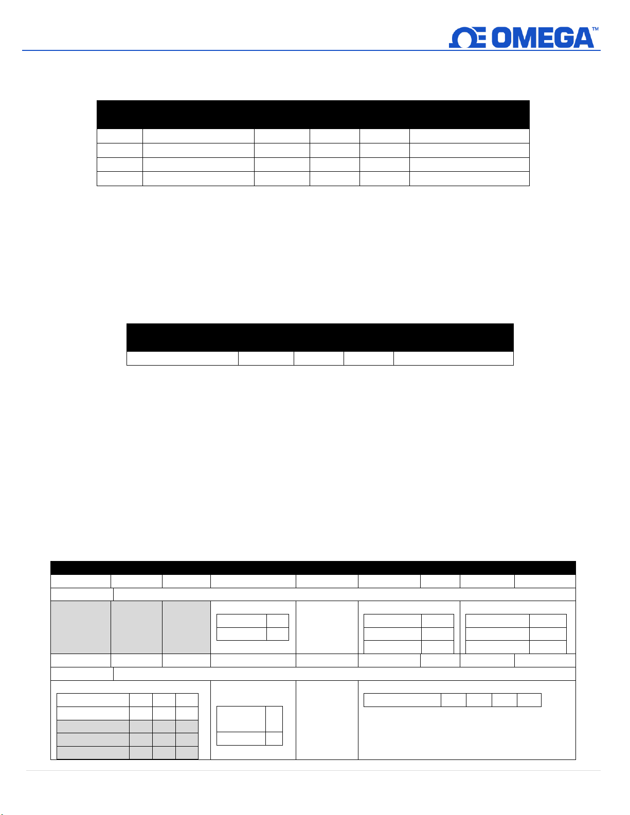
Each output has a name. The default names for the outputs are Output_0 through Output_3. The default
names may be overwritten, such as ‘Stack_Lite’ or ‘Control_Valve’. Names are restricted to 16 characters.
Output Name
0 Output 0 Name 0xf078 0xf720 char[16] Defaults to Output_0
1 Output 1 Name 0xf07a 0xf728 char[16] Defaults to Output_1
2 Output 2 Name 0xf07c 0xf730 char[16] Defaults to Output_2
3 Output 3 Name 0xf07e 0xf738 char[16] Defaults to Output_3
The Output names are retained until a factory reset occurs.
It is strongly recommended that:
1. Spaces within the name should be replaced with the ‘_’ character.
2. All output names on a particular device are unique – if duplicate functions are supported append a ‘_x’
string, where x represents the instance. For example, Stack_Lite_1 and Stack_Lite_2 could be used if 2
stack lights are being connected.
9.4.4 Process Temperature
The process fluid temperature can be obtained by reading the below register. The value is returned as a
single precision floating point (4 bytes).
Name
Process Temperature
9.5 4-20 mA Output Configuration
4-20 mA outputs are widely used due to several advantages over-voltage outputs:
Modbus
Address
Modbus
Address
I2C
Address
I2C
Address
Size Description
Size Description
0xF01E 0x003C float Process Temperature
1. Higher noise immunity
2. Ability to power the sensing device using the measurement current – provided total power is less than ~ 3.5
mA X minimum loop voltage.
3. Automatic wire break detection – if the signal wires break the current drops to 0 mA, allowing the control
system to detect the fault.
4. Automatic wire short detection – if the signal wires are shorted the current will exceed the specified 20 mA,
allowing the control system to detect the fault.
The HANI™ Clamp Temperature Sensor 4-20 mA Loop Powered device requires a minimum loop voltage of 8.0
volts, allowing the device to be powered using conventional 4-20 mA control signals. The factory default
configuration connects the measured temperature to the 4-20 mA output signal.
4-20 mA Output Configuration
7 6 5 4 3 2 1 0
Output Configuration
0 0 0 System Error
3.8 mA 0
21.5 mA 1
High Range Error
3.8 mA 0
21.5 mA 1
Pass-thru 2 (3)
Low Range Error
3.8 mA 0
21.5 mA 1
Pass-thru 2 (3)
15 14 13 12 11 10 9 8
Output Type
Sensor Mapping
No Mapping 0 - -
Sensor 0 1 0 0
Sensor 1 1 0 1
Sensor 2 1 1 0
Mapping
Enabled
Not
0
Enabled
Enabled 1
Output Type
4-20 mA 0 1 0 0
Sensor 3 1 1 1
29 | H A N I ™
Page 30
30 | H A N I ™
UNRESTRICTED
9.5.1 High Range / Low Range
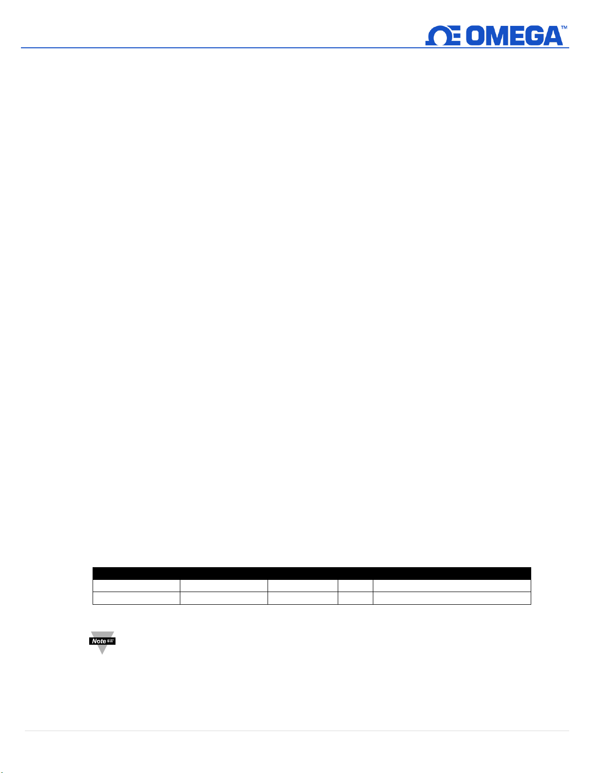
The High Range and Low Range configuration values determine what 4-20 mA signal is generated if the signal
is above or below the specified input range. The pass-thru option indicates that the output signal is not
clamped.
If the Measured Value exceeds the user-defined Input Maximum an Over-Range condition exists. The 4-20
mA output may be configured to generate a Fault High (21.5 mA) current or a Fault Low (3.8 mA) current
when an Over Range condition occurs.
Similarly, if the Measured Value is less than the user-defined Input Minimum an Under-Range condition
exists, and the output may be configured to generate either a Fault High or Fault Low output.
A Loop Error occurs if the applied voltage of the 4-20 mA loop drops below the specified minimum loop
voltage and the output will be driven to a low Error level of ~ 3.5 mA.
9.5.2 System Error
The System Error setting defines whether the output is driven to a low current or high current if an internal
system error occurs.
9.5.3 Output Type
The Output Type is fixed as a 4-20 mA output.
9.5.4 Mapping Enabled
If set, the read-only Mapping Enabled bit indicates that the output may be optionally directly mapped to a
sensor input. If the Mapping Enabled bit is clear no mapping is supported, and the Sensor Mapping field is
ignored.
9.5.5 Output Mapping
The Output Mapping value may select ‘no mapping’ or Sensor 0 through 3. If no mapping is selected the 4-20
mA output may be directly controlled by writing a value from 0 – 100 % (0 mA to 24 mA) to the internal
Output Value. If a Sensor is selected the 4-20 mA output will be scaled to track the measured sensor value
between the Scale Low and Scale High range.
If no sensor mapping is in place the output value is determined by the percent activation applied (0 – 100 %).
For example, 50% excitation generates an output current of 12 mA, whereas an 75% activation generate an
output of (75 / 100 ) * 24 mA == 18 mA.
9.5.6 Scaling Minimum/Maximum Values
When Sensor Mapping is used with the 4-20mA output, the user may specify the input signal range through
the Scaling Minimum and Scaling Maximum parameters.
Name
Modbus Address
I2C Address
Size
Description
Scaling Minimum
0xf1f0
0x03e0
float
Sets lower input range
Scaling Maximum
0xf1f2
0x03e4
float
Sets upper input range
Note: Due to the Loop Power requirements specifying an output value below 15% (3.5 mA) will
typically be clamped at 3.6 mA.
9.5.7 4-20 mA Loop Powered Error
A Loop Error occurs if the applied voltage of the 4-20 mA loop drops below the specified minimum loop
voltage and the output will be driven to a low Error level of ~ 3.5 mA.
Page 31
31 | H A N I ™
UNRESTRICTED
9.6 Digital Output Configuration
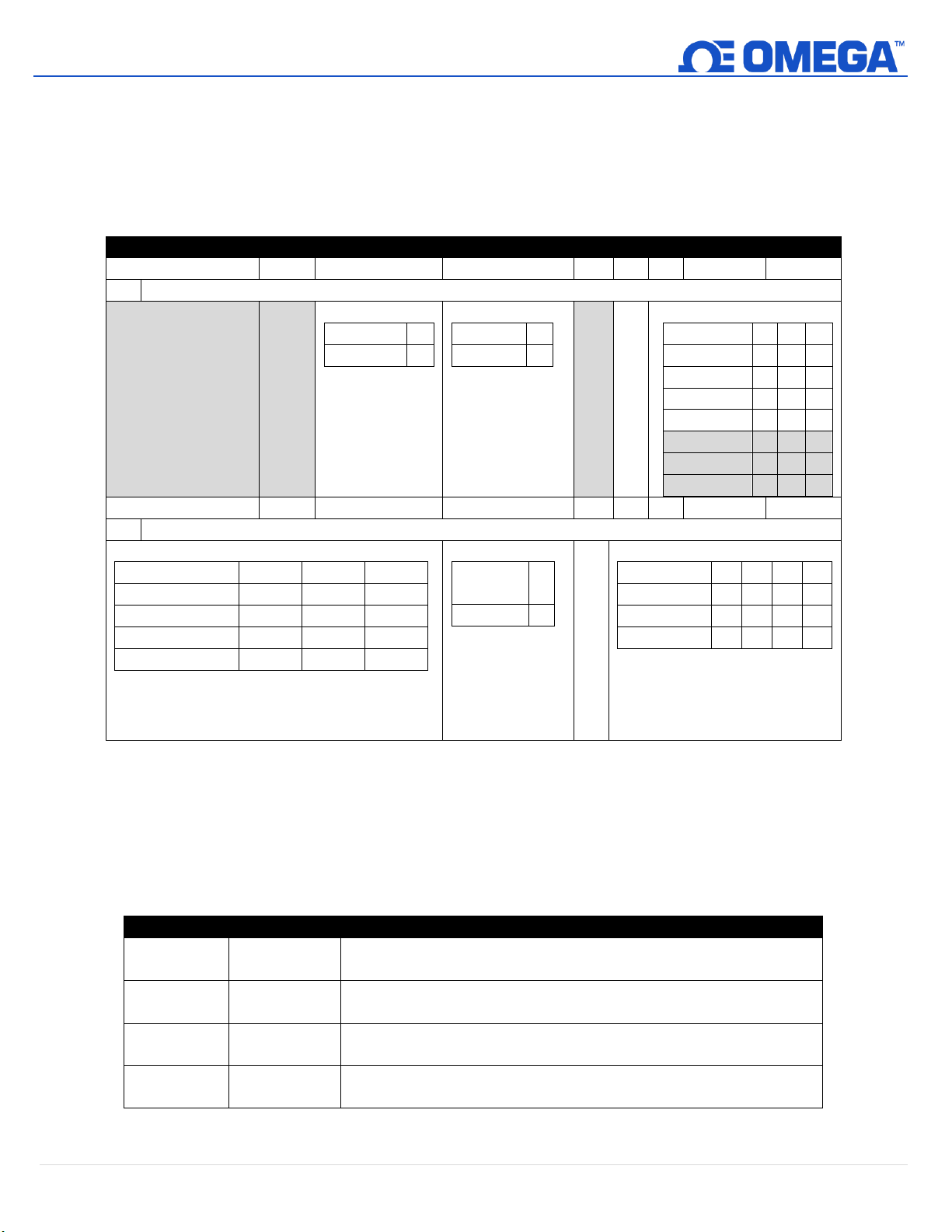
The Digital output option provides two output signals which may be configured for ON/OFF, PWM, or SERVO
outputs through the Output Configuration registers. The remaining outputs are assigned as phantom devices
which are non-configurable.
The highlighted entries show typical default configurations.
Digital Output Configuration
7 6 5
4
3 2 1 0
Output Configuration
Servo Range
1.0 – 2.0
0
0.5 – 2.5
1
Active State
LOW
0
HIGH
1
Rate
100 Hz
0 0 0
10 Hz
0 0 1
1 Hz
0 1 0
0.1 Hz
0 1 1
50 Hz
1 0 0
33 Hz
1 0 1
25 Hz
1 1 0
20 Hz
1 1 1
15
14
13
12
11 10 9 8
Output Type
Sensor Mapping
No Mapping
0 - -
Sensor 0
1 0 0
Sensor 1
1 0 1
Sensor 2
1 1 0
Sensor 3
1 1 1
Mapping Enable
Not
Enabled
0
Enabled
1
Output Type
Null
0 0 0 0 ON/OFF
0 0 0 1 PWM
0 0 1 0 Servo
0 0 1
1
9.6.1 Rate
The Rate determines the repetition rate, or frequency, of the Digital Output. For On/Off outputs the rate
field is ignored.
9.6.1.1 PWM Rate
The Digital output supports the following PWM frequencies:
PWM Rate
Name
Description
0
100 Hz
PWM signal has constant 100 Hertz frequency (10 msec repetition
rate) with 0 – 100 % duty cycle
1
10 Hz
PWM signal has constant 10 Hertz frequency (100 msec repetition
rate) with 0 – 100 % duty cycle
2
1 Hz
PWM signal has constant 1 Hertz frequency (1 sec repetition rate)
with 0 – 100 % duty cycle
3
0.1 Hz
PWM signal has constant 0.1 Hertz frequency (10 second
repetition rate) with 0 – 100 % duty cycle
Page 32
32 | H A N I ™
UNRESTRICTED
9.6.1.2 SERVO Rate
Smart Sensor probes support the following SERVO frequencies:
PWM Rate
Name
Description
0
100 Hz
PWM signal has constant 100 Hertz frequency (10 msec repetition
rate) with 0 – 100 % duty cycle
4
50 Hz
PWM signal has constant 50 Hertz frequency (20 msec repetition
rate) with 0 – 100 % duty cycle
9.6.2 Output Type
Smart Sensor probes support NULL (0), ON/OFF (1), PWM (2) and SERVO (3) outputs. When set to NULL the
output signal will be left in a high impedance state. When set to ON/OFF the Rate and Servo Range controls
have no effect. When the SERVO type is selected the Duty-Cycle is restricted so the output signal is either
0.5 – 2.5 msec or 1.0 to 2.0 msec based on the Servo Range bit.
9.6.3 Active State
Smart Sensor digital outputs may be configured as Active HIGH or Active LOW. When set to 1 (Active High),
the output will be high impedance when active. When set to 0 (Active Low), the output will be low
impedance (~ 0.0 volts) when active. The Factory reset value is 0 (Low).
9.6.4 Mapping Enabled
The read-only Mapping Enabled bit indicates that the output may be optionally directly mapped to a sensor
input based on the Sensor Mapping field. If the Mapping Enabled bit is clear no mapping is supported, and
the Sensor Mapping field is ignored.
9.6.5 Output Mapping
The Output Mapping value may select ‘no mapping’ or any of Sensor 0..3. If no mapping is selected the
output may be directly controlled by writing a value from 0 – 100 % to the internal Output Value. If a Sensor
is selected and the hardware supports the mapping the output will track the selected sensor value, scaled by
the Output Minimum and Output Maximum values.
If Output Mapping is enabled for PWM outputs the scaling values are used such that a signal input at or
below the Scaling Low-value results in a 0% output and a signal input at or above the Scaling High-value
results in a 100% PWM duty cycle.
If Output Mapping is enabled for SERVO outputs the scaling values are used such that a signal input at or
below the Scaling Low-value results in a minimum (0.5 or 1.0 msec) pulse width and a signal input at or
above the Scaling High-value results in a maximum (2.0 or 2.5 msec) pulse width.
 Loading...