

Page 1
User’s
Guide
Shop online at omega.com
e-mail: [email protected]
For latest product manuals: omega.com/en-us/pdf-manuals
HHF143 Series
Handheld Rotating High-Accuracy
Metal-Vaned Digital Thermo-Anemometers
Page 1 of 24
M4750/1222
Page 2

omega.com [email protected]
Servicing North America:
U.S.A.
Headquarters: Toll-Free: 1-800-826-6342 (USA & Canada only)
Omega Engineering, Inc.
Customer Service: 1-800-622-2378 (USA & Canada only)
Engineering Service: 1-800-872-9436 (USA & Canada only)
Tel: (203) 359-1660
e-mail: [email protected]
For Other Locations Visit
omega.com/worldwide
Fax: (203) 359-7700
The information contained in this document is believed to be correct, but OMEGA accepts no liability for any
errors it con tains and reserves the right to alter specifications without notice.
M4750/1222
Page 2 of 24
Page 3
INTRODUCTION
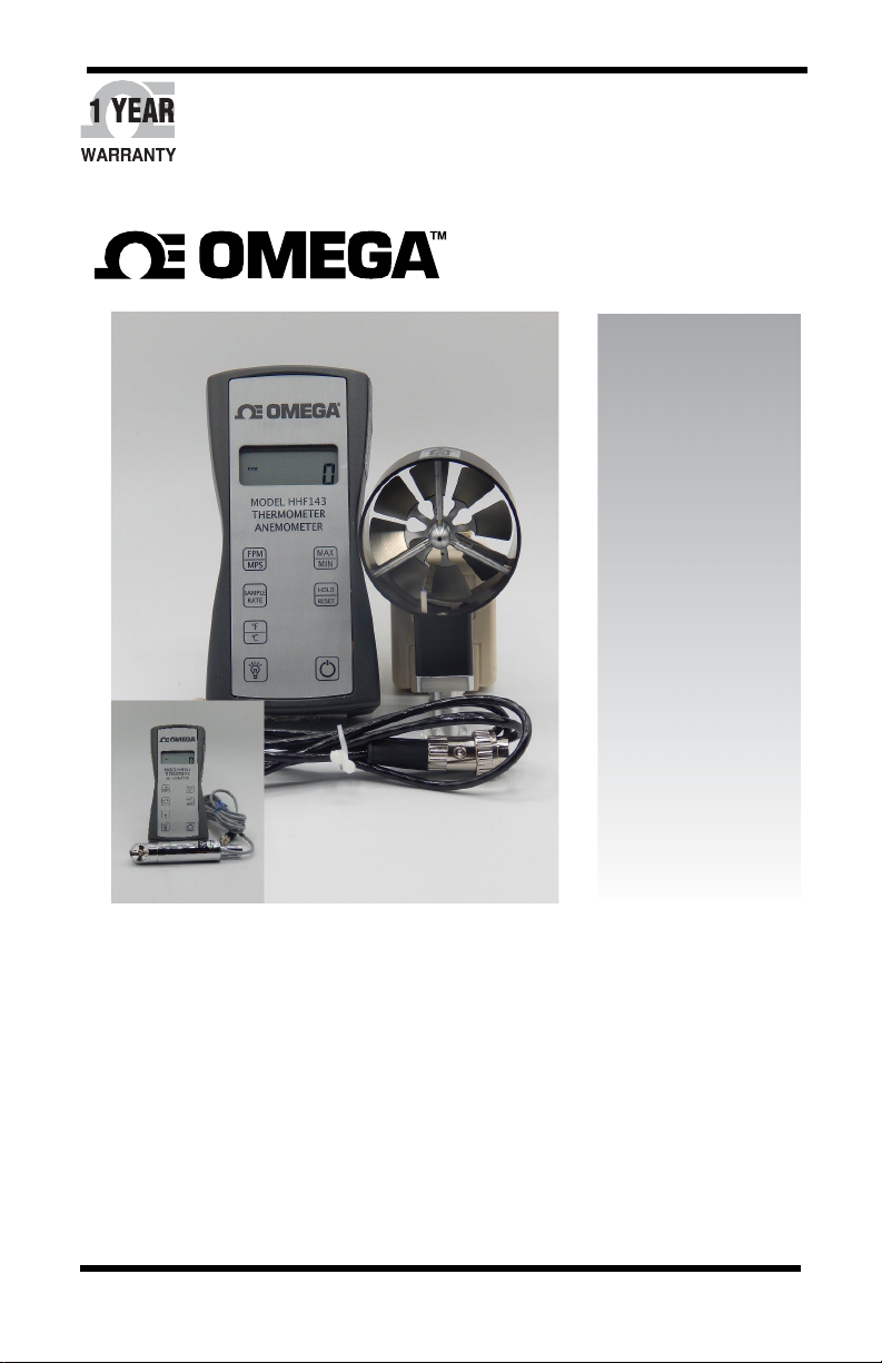
Omega’s Model HHF143 digital thermo-anemometer is a versatile instrument
for measuring air velocity and temperature in various applications such as
HVAC, aerospace development, industrial process airflow, and fluids research.
The rugged yet precise probe can be used for airstreams that have a wide range
of humidity, temperature, and contaminants without compromising accuracy.
Features include custom cable lengths, service temperatures up to 212˚F (100˚C)
at the probe, high reliability, and long life.
This manual has been prepared for both HHF143A (1.00” probe) and HHF143B
(2.75” probe) models including all optional outputs.
IMPORTANT SAFETY INFORMATION
Classifications
Danger: To Prevent Serious Injury or Death
Warnings in this classification indicate danger that may result in serious injury or death if
not observed.
Caution: To Prevent Damage to the Product
Warnings in this classification indicate risks of damage to the product that may void the
product warranty and/or calibration.
Description of Symbols
ESD Caution: To Prevent Damage to the Product
Warnings in this classification indicate risks of damage to the product that may void the
product warranty and/or calibration. Internal components are static sensitive and are not
user serviceable. Opening the cases by a non-authorized service center and/or in a nonESD safe environment may cause damage not covered by the manufacturer’s warranty.
Important: Mandatory Action Required
The specific action is given near this symbol.
M4750/1222
Page 3 of 24
Page 4

COMPLIANCE INFORMATION
FCC Compliance Statement
This equipment has been tested and found to comply with the limits for a Class B digital device,
pursuant to part 15 of the FCC rules. These limits are designed to provide reasonable protection
against harmful interference. This equipment generates, uses, and can radiate radio frequency energy
and, if not installed and used in accordance with the instructions, may cause harmful interference to
radio communications. However, there is no guarantee that interference will not occur in a particular
situation.
EU – Declaration of Conformity
Miltronics Mfg. Svcs., Inc. (the manufacturer) declares that the product for this manual demonstrates
compliance with the requirements of:
A copy of the Declaration of Conformities (DoC) is available on request from the address found in
this manual, on the last page.
UKCA – Declaration of Conformity
Miltronics Mfg. Svcs., Inc. (the manufacturer) declares that the product for this manual demonstrates
compliance with the requirements of:
A copy of the Declaration of Conformities (DoC) is available on request from the address found in
this manual, on the last page.
RoHS Statement
Miltronics Mfg. Svcs., Inc. (the manufacturer) declares that to the best of our knowledge, based on
supplier provided information, the product for this manual demonstrates compliance with the
requirements of:
and is not intentionally manufactured with, formulated with, or contains amounts greater than
maximum concentration values by weight in homogenous materials of the following substances:
Please be advised that we do not analyze for these substances.
WEEE – Waste Electrical and Electronic Equipment - 2012/19/EU
Miltronics Mfg. Svcs., Inc. (the manufacturer) asks that all our products to be recycled at the end of
their current use, to comply with local waste requirements. We support local Waste Electrical and
Electronic Equipment (WEEE) directives where they are in operation. That means that WEEE
products may not be disposed as unsorted municipal waste but is to be collected separately. These
products are therefore labeled with a crossed-out “wheelie-bin” symbol which you can see above.
WEEE products may contain hazardous substances which may negatively affect the environment
and human health when disposed of through normal channels. We are committed to reduce the
negative environmental and human health effects of WEEE.
• European Community Council Directive 2014/30/EU
• UKCA Electromagnetic Compatibility Regulations 2016.
• RoHS Directive: 2015/863/EU
• Restriction of the Use of Certain Hazardous Substances in Electrical and Electronic
Equipment Regulations 2012 (as amended): Great Britain
• Restriction of the Use of Certain Hazardous Substances in Electrical and Electronic
Equipment Regulations 2012 (as amended): Northern Ireland
• Lead (Pb), Mercury (Hg), Hexavalent Chromium (Cr VI), Polybrominated Biphenyls
(PBB), Polybrominated Diphenyl Ethers (PBDE), Bis(2-Ethylhexyl) phthalate (DEHP),
Benzyl butyl phthalate (BBP), Dibutyl phthalate (DBP), and Di isobutyl phthalate
(DIBP): 0,1 % or 1000 ppm
• Cadmium (Cd): 0,01 % or 100 ppm
M4750/1222
Page 4 of 24
Page 5
DANGER
Never touch the vane assembly blades and/or thermal sensors.
The vane assembly blades may contain sharp edges which may cause minor
cuts. The assembly contains precision bearings which are sensitive, and the
blades are finely adjusted to specific pitches. Touching this assembly or its parts
may cause damage which can affect its operation and the calibration.
NOTE: If the vane assembly head or probe head requires cleaning, we
recommend a fine mist of isopropyl alcohol and a fine long-haired brush or send
the unit in or servicing.
Do not disassemble or heat the batteries or put them into a fire.
They may cause burns and the batteries may burst. Please dispose of used
batteries in the proper manner per local ordinances.
CAUTION
When measuring, ensure that the direction arrow is facing the
direction of airflow.
The arrow indicates the direction of airflow for the data provided on the calibration
certificate. It is meant to allow for uniform and consistent readings as per the provided
data. The probe will operate in the opposite direction, but the data may be different.
Do not use or leave the instrument in a high temperature, high humidity,
high speed airflows or dusty environments for prolonged periods.
The instrument may not function properly out of the specified operating conditions and/or
have a greatly reduced operating life span.
Do not subject the instrument or the probe to strong impacts.
Dropping the instrument or the probe may cause damage or malfunction to the instrument
and may change the calibration data. We recommend sending it in immediately to be
checked.
M4750/1222
Page 5 of 24
Page 6
CAUTION (continued)
Never disassemble, modify, or repair the product.
Failure to observe the above may cause damage to the instrument or the probe. It may
also void the manufacturer’s warranty and calibration certificate.
Do not pick up or carry the instrument by the cable.
It may cause a malfunction or damage to the wiring of the cable.
Remove the batteries from the instrument when storing for long
periods of time. When inserting the batteries, be sure to insert them with the
polarity facing the correct direction.
Failure to do so may cause battery leakage and subsequent damage to the
instrument. The manufacturer does not recommend any specific brand of
batteries, but a high-quality name brand alkaline battery seems to last the
longest.
Do not wipe the instrument with a volatile solvent.
Use neutral solvents and simple cleaners to clean the instrument with a soft cloth.
Regularly check the head of the probe for contamination.
Impurities (such as dust) on the blades and/or thermal sensor may affect the
accuracy of the instrument.
NOTE: If the vane assembly head or probe head requires cleaning, we
recommend a fine mist of isopropyl alcohol and a fine long-haired brush or send
the unit in or servicing.
disconnecting the cable(s) and returning it to the original carrying case.
When storing or shipping the instrument, the manufacturer recommends
M4750/1222
Page 6 of 24
Page 7

SECTION 1 - SPECIFICATIONS
Ranges:
Probe APT275: 50 to 7800 ft/min (feet per minute)
0.25 to 39.60 m/sec (meters per second)
Air Probe APT100: 300 to 6890 ft/min (1.50 to 35.00 m/sec)
Accuracy:
Air Velocity: APT275: ± 1.0% of reading ±1 digit
APT100: ± (0.50% of F.S. + 0.75% of reading + 1 digit)
Temperature: ± (0.3°C + 0.2% of reading in °C)
Temperature accuracy examples: ±0.3°C at 20°C
±0.5°F at 68°F
Resolution:
Air Velocity: 1 ft/min or 0.01 m/sec
Temperature: 0.1˚F or 0.1˚C
Operating Temperature:
Instrument: 32˚ to 125˚F (0˚ to 50˚C)
Air Probes: -4˚ to 212˚F (-20˚ to 100˚C)
Power Supply: 3 AA alkaline batteries
Battery Life: Approx. 150 hours, without backlight
Battery check: Automatic low battery display
Display: 0.5” LCD, 4 digits, with LED backlight
M4750/1222
Page 7 of 24
Page 8

OPTIONS AND COMPONENTS
Options Available:
• Protective Boot and Splash-Proof Seal for the Instrument
• USB Communications
• RS232 Communications
• Analog 0-5 Volt Output
• Wall Transformer Power for the Instrument (US only)
• Additional Probes, 2.75-inch diameter or 1 inch diameter
• High-temperature probes: Insertion, Immersion, Surface, and Air
• Extra extension and/or flexible rods
• 8-ft Telescopic Extension Rod
• Custom cable lengths, in 5-ft increments, up to 100-ft (30-
meters).
• Custom probe connections.
Included:
• (1) HHF143 Instrument
• (1) Vane-type probe head, choice of 2.75-inch diameter or 1 inch
diameter
• (3) Rigid extension rods with handle grip
• (1) Flexible extension rod
• (1) Probe connection cable, 5 ft.
• (3) Size AA 1.5V alkaline batteries
• (1) Hard-shell carrying case with foam liner
• (1) Operation Manual
(installed in instrument)
M4750/1222
Page 8 of 24
Page 9
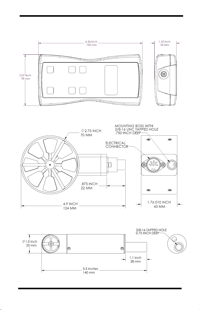
INSTRUMENT
2.75 INCH PROBE
1 INCH PROBE
DIMENSIONS
Page 9 of 24
M4750/1222
Page 10
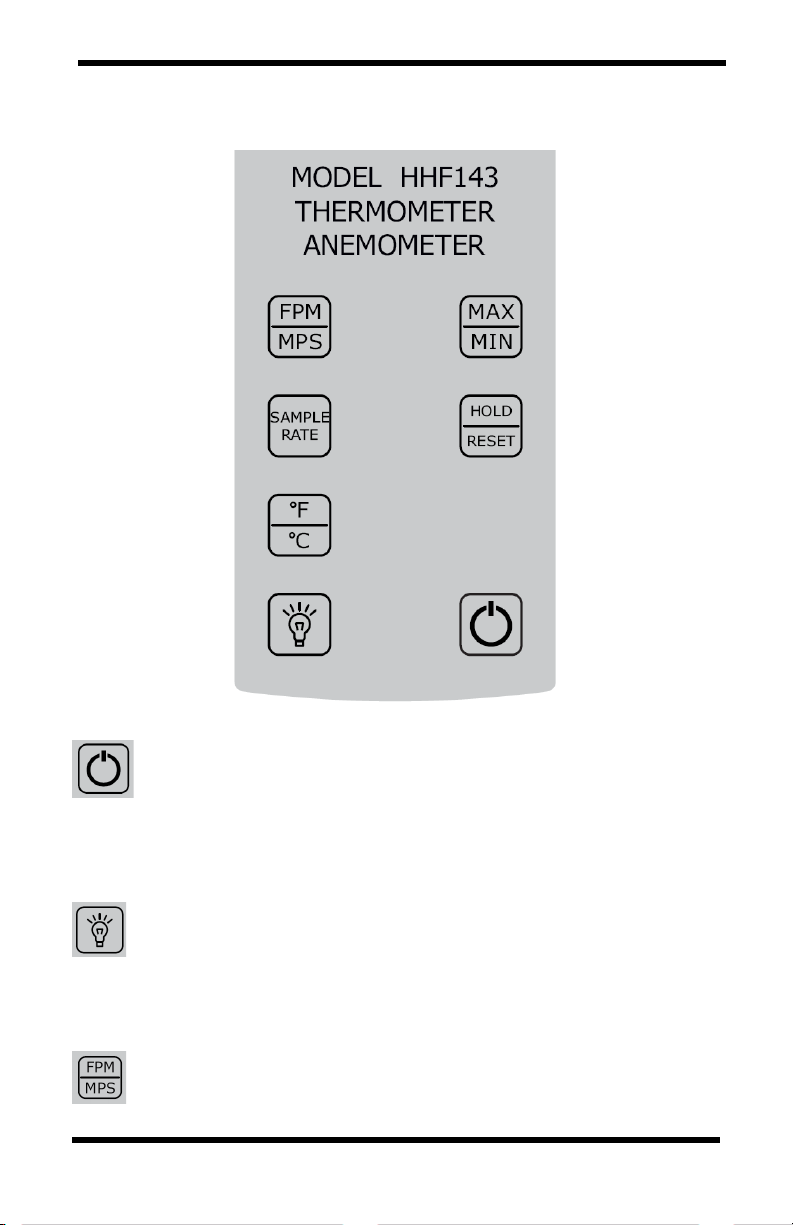
SECTION 2 – SWITCH FUNCTIONS
Pressing the ON/OFF key switches the instrument ON. Hold down
the key for 2 seconds to switch the unit OFF. The unit will
automatically power off after 30 minutes without any key presses. To
disable auto power-off, hold down the power button during turn-on. The unit
will flash AOFF, which means that the auto power-off has been disabled. The
auto power-off is re-enabled each time the instrument is turned on.
Press the BACKLIGHT key to turn the LCD backlight on for 30
seconds. To turn the backlight on permanently, hold the backlight key
down for 3 seconds. The LCD will flash. The backlight is now switched on
permanently. To switch the backlight off, press the backlight key again.
Press the FPM/MPS key to switch the measurement units from FPM
(feet per minute, 1 FPM resolution) to MPS (meters per second, 0.01
MPS resolution).
M4750/1222
Page 10 of 24
Page 11
SECTION 2 – continued
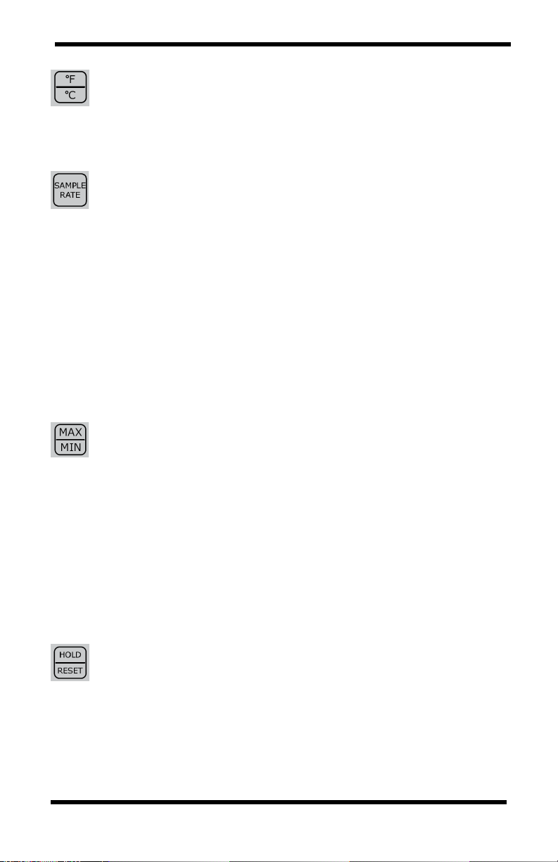
Press the TEMPERATURE key to display the current temperature of
the air stream as measured by the Air Probe. To switch the units
between degrees Fahrenheit (°F) and degrees Celsius (°C), press
the TEMPERATURE key again. Either °C or °F will be displayed along with
the reading.
Press the SAMPLE RATE key to change the measurement averaging rate
(“sample rate”) of the unit:
2 sec An average value of airspeed measurements during the preceding 2 seconds is
displayed.
4 sec An average value of airspeed measurements during the preceding 4 seconds is
displayed.
8 sec An average value of airspeed measurements during the preceding 8 seconds is
displayed.
16 s An average value of airspeed measurements during the preceding 16 seconds is
displayed.
Note: The sample rate for temperature readings is always 2 seconds.
Press the MAX/MIN key to record and display the maximum airspeed reading.
The maximum airspeed reading display will alternate with the letter “H”
displayed with the sample rate. Press the MAX/MIN key again to record and
hold the minimum airspeed reading. The minimum airspeed
reading display will alternate with the letter “L” displayed with the sample rate.
For example:
1065 alternating with h 8 signifies that 1065 is the highest airspeed reading since
the MAX/MIN key was pressed, and the sample rate is set to 8 seconds.
82 alternating with l 16 signifies that 82 is the lowest airspeed reading since the
MAX/MIN key was pressed, and the sample rate is set to 16 seconds.
To exit MAX/MIN mode, press the SAMPLE RATE key.
Press the HOLD/RESET key to freeze the current reading on the display.
HOLD is displayed on the LCD and the reading is held.
Press the HOLD/RESET key a second time to clear this mode and return the unit
to normal operation.
Press the HOLD/RESET key while in MIN/MAX mode to display BOTH the minimum
and maximum airspeed reading since the MAX/MIN key was pressed. Once the
HOLD/RESET key is pressed while in MAX/MIN mode, new airspeed readings are no
longer recorded. To return to MAX/MIN mode, press the HOLD/RESET key again.
M4750/1222
Page 11 of 24
Page 12
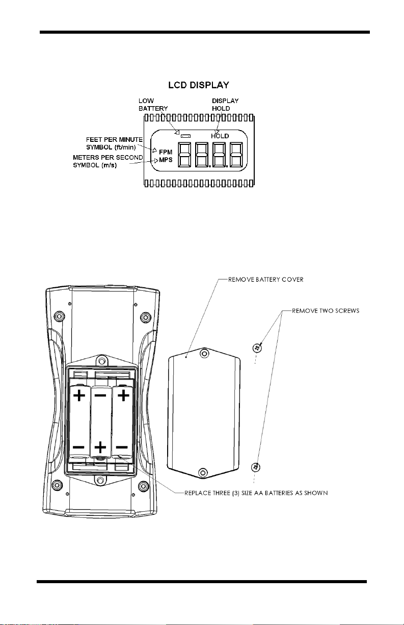
APPENDIX A – LCD DISPLAY SYMBOLS
APPENDIX B – BATTERY REPLACEMENT
Page 12 of 24
M4750/1222
Page 13
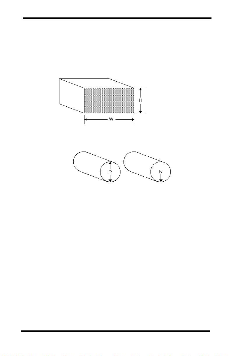
APPENDIX C – AIRFLOW VOLUME CALCULATIONS
To calculate cubic feet per minute (CFM) from a measured air velocity (FPM),
you need the calculated cross-sectional area of the air flow stream:
Volume Flow (CFM) = Velocity (FPM) X Area (sq ft).
In a rectangular duct this cross-sectional area equals the Width times the Height.
W x H=A (cross-sectional area)
In a circular duct this cross-section area equals the radius squared times π (3.14).
R x R x 3.14=A (cross-sectional area)
To convert an area calculated in square inches to an area calculated in square
feet (which is required for the Volume Flow equation above) divide by 144:
(area in sq in.)/144 = (area in sq ft.).
Example: The air duct is rectangular; the width is 24 in., and the height
is 12 in. The air velocity reading through the duct is 450 FPM.
Calculate the Volume Flow.
Step 1: Cross-sectional area = 24 in. x 12 in. = 288 sq in.
Step 2: 288 sq in /144 = 2 sq ft.
Step 3: Volume flow = Air Velocity x Area, therefore,
Volume flow rate = 450 FPM x 2 sq ft. = 900 CFM.
M4750/1222
Page 13 of 24
Page 14
Corresponding
Wire
Analog
Output
Measurement
Equation* to convert
from
Color
Pin
#
Function
Voltage
Range
Range
Volts (V) to Measurement
Value
BLK 1 Ground
--- N/A ---
--- N/A ---
--- N/A ---
GRN 2 Air Velocity
0 to 5
Volts
0 to 10,000
FPM
Air Velocity = 2000×V
GRY 3 --- Not Used ---
--- N/A ---
--- N/A ---
--- N/A ---
WHT
4
--- Not Used ---
--- N/A ---
--- N/A ---
--- N/A ---
APPENDIX D – ANALOG OUTPUTS (IF EQUIPPED)
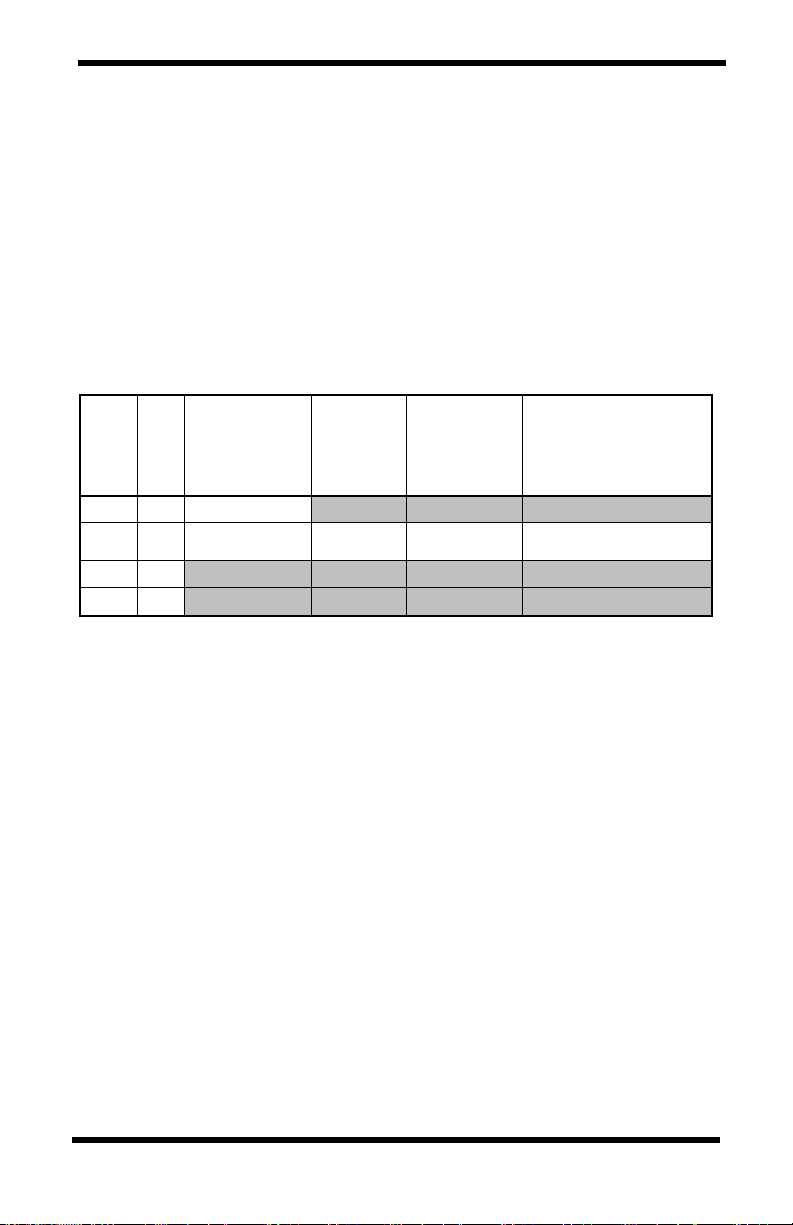
If the instrument is equipped with the analog output option, there will be a fivepin connector on the bottom of the instrument. Also, an analog output cable will
be included with the instrument. This cable will have a five-pin connector on
one end and four tinned wires on the other end.
The instrument will output a Voltage between 0 and 5 Volts that corresponds to
the Air Velocity measured by the instrument. The output range, pin
assignments, and wire colors are given in the table below. Also shown is a
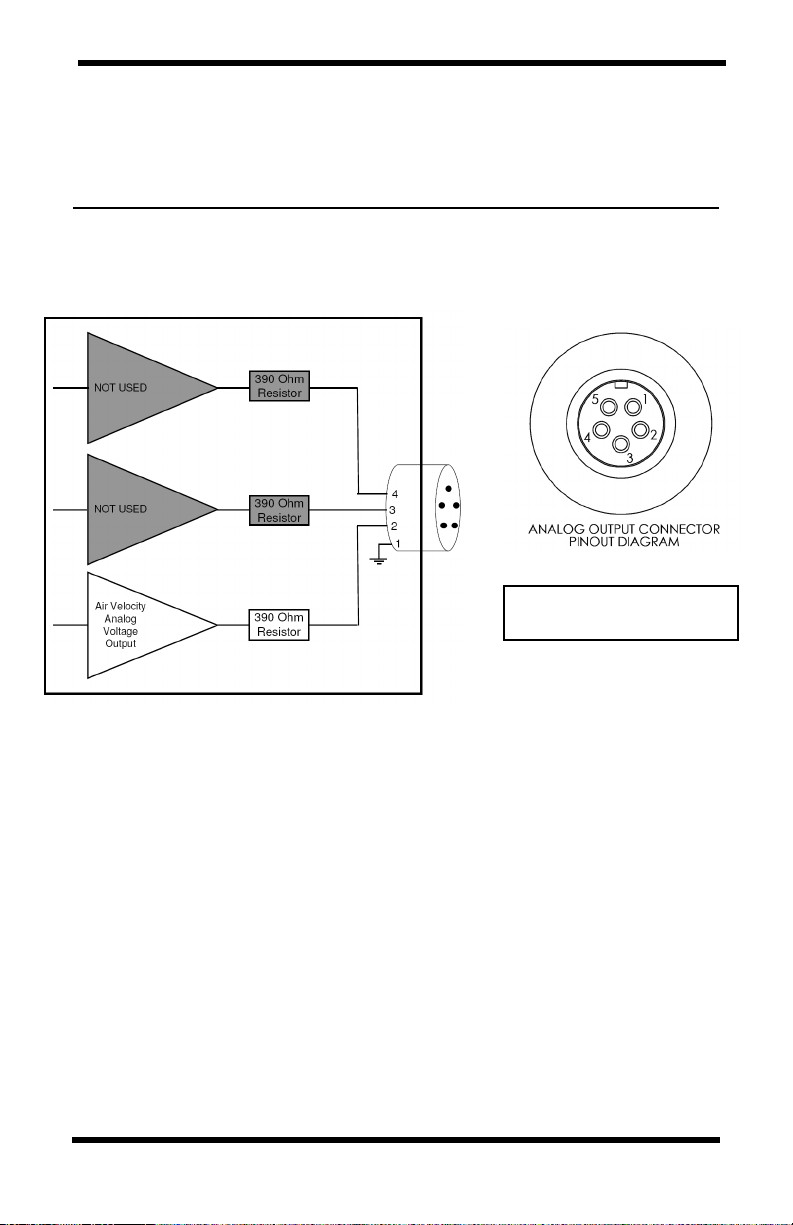
block diagram of the analog output circuit.
*To convert from Volts to Air Velocity in Feet per Minute, multiply by 2000.
► For example, an analog output of 2.375 Volts means that the instrument is
measuring an air velocity of 4750 feet per minute (FPM).
► 2.375 Volts
Note: When using analog outputs, there is an additional ±1% error in the
analog output voltage. This is in addition to the normal measurement error.
► For example, an air velocity reading of 500 FPM would normally have an
accuracy of ±1% of reading ±1 digit (±6 FPM) when the data is viewed
on the LCD display.
► With the additional error associated with the analog output voltage, the
effective accuracy of the analog output for this air velocity measurement
will be ±2% of reading ±1 digit (±11 FPM).
Custom Analog Voltage Outputs are also available – contact Omega for details.
Page 14 of 24
× 2000 = 4750 FPM
M4750/1222
Page 15
Mating Cable Connector:
Binder Part No. 99-0413-00-05
APPENDIX D – continued
Analog Output circuit block diagram and connector pin assignment
Page 15 of 24
M4750/1222
Page 16

APPENDIX E - USB DATA OUTPUT (IF EQUIPPED)
If the instrument is equipped with the USB Communications option, there will
be a four-pin male connector on the bottom of the instrument. Also, a USB
cable will be included with the instrument. This cable will have a four-pin
female connector on one end and a USB Type-A connector on the other end.
USB Data Output – Instructions for Use
STEP 1: Install a Virtual COM Port (VCP) Driver on your computer.
Free VCP drivers can be downloaded for Windows, Linux, and MAC
from FTDI Ltd on their website:
http://www.ftdichip.com/Drivers/VCP.htm
We recommend downloading the setup executable, which
automatically runs and configures the drivers for you.
STEP 2: Connect the USB cable (included) to the male connector on the
bottom of your instrument. Connect the other end to a USB port on
your computer.
STEP 3: Turn the Instrument ON.
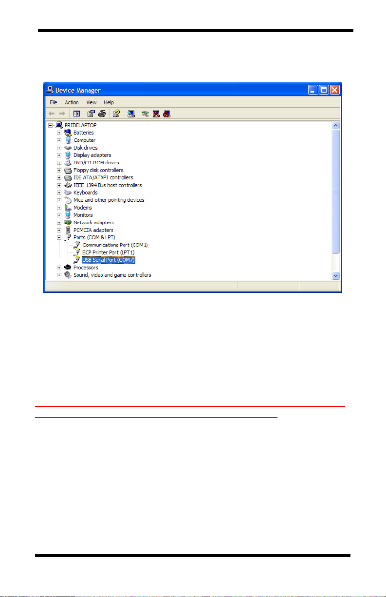
STEP 4: Verify that the Instrument has been set up as a USB Serial Port with
a unique COM port number. (You only need to do this once)
For Windows users, open the Windows Device Manager (found in
Control Panel) and verify that a USB serial port exists as shown
below.
Page 16 of 24
M4750/1222
Page 17
APPENDIX E – continued
You are now ready to capture the data being measured by your
instrument.
Please refer to Appendix G – Viewing and Capturing Data for
further instructions.
NOTE: Units with USB or RS232 communications, output only Air data at
this time. Temperature data is not available on the output.
M4750/1222
Page 17 of 24
Page 18

APPENDIX F – RS232 COMMUNICATIONS (IF EQUIPPED)
If the instrument is equipped with the RS232 Communications option, there will
be a three-pin male connector on the bottom of the instrument. Also, an RS232
cable will be included with the instrument. This cable will have a three-pin
female connector on one end and a DB9 Female connector on the other end.
RS232 Data Output – Instructions for Use
STEP 1: Connect the RS232 cable (included) to the female connector on the
bottom of your instrument. Connect the other end to an RS232 port
on your computer.
STEP 3: Turn the Instrument ON.
STEP 4: Verify that the Instrument has been set up as a RS232 Serial Port
with a unique COM port number. (You only need to do this once).
For Windows users, open the Windows Device Manager (found in
Control Panel) and verify that a serial port exists.
You are now ready to capture the data being measured by your
instrument.
Please refer to Appendix G – Viewing and Capturing Data for
further instructions.
M4750/1222
Page 18 of 24
Page 19
APPENDIX G – VIEWING AND CAPTURING DATA
(IF EQUIPPED WITH EITHER USB OR RS232 OUTPUTS)
NOTE: HyperTerminal is no longer included with Windows Vista or later packages.
Previous manuals referenced this program. We now reference, Parallax Serial Terminal.
There are many terminal emulator programs available on the market. It is up to the
end-user to determine which program is compatible with his/her system, what settings
it may require, and the Omega Engineering product being used. Omega Engineering
does not endorse or recommend any of these programs and assumes no liability for
their use.
There are many ways to capture the serial port data from the instrument. The
simplest method is to use a terminal emulator program.
Using a terminal emulator allows the serial COM port to be opened, with the
below port settings, and real-time data to be viewed from the instrument. One
such terminal emulator program is Parallax Serial Terminal, available from
www.parallax.com
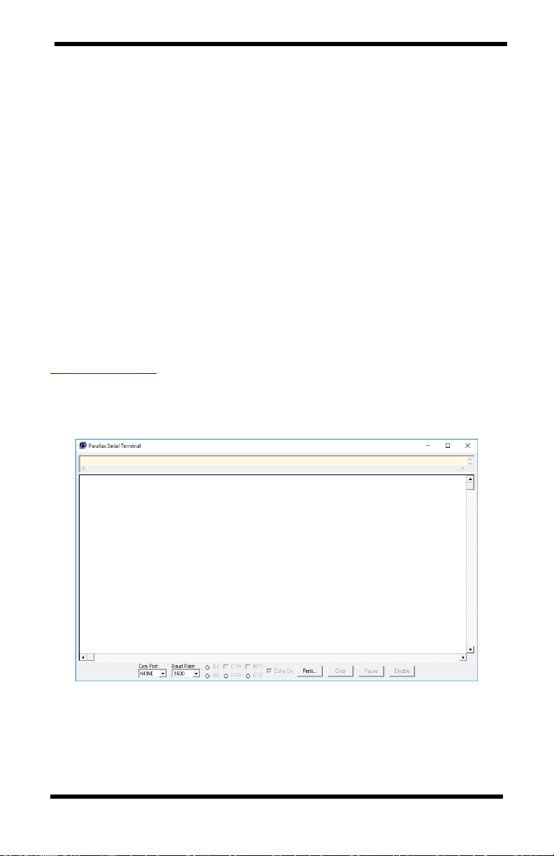
Open the Parallax Serial Terminal, based on how you installed the program onto
your computer. The below screen will come up.
.
Attach your instrument & probe to your computer via the USB cable.
Select the appropriate ‘Com Port:’. In the below example, COM5 is being used.
Set the ‘Baud Rate:’ to 9600
M4750/1222
Page 19 of 24
Page 20
APPENDIX G – continued
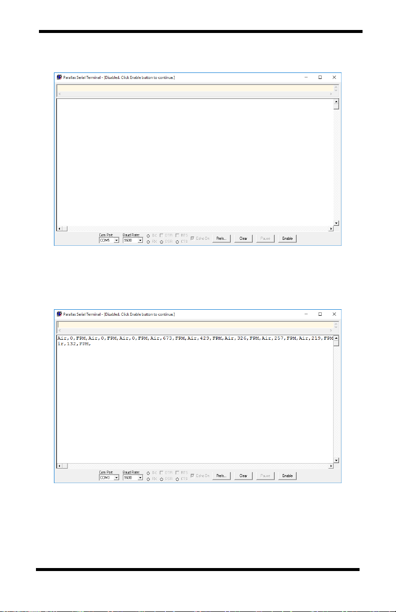
You will now receive data from your instrument. The graphic below shows the
serial port output data from Parallax Serial Terminal when connected to an
Omega HHF143 Instrument.
Graphics may vary.
M4750/1222
Page 20 of 24
Page 21

APPENDIX G – continued
Serial Port Settings
Bits per Second (Baud) 9600
Serial Port Protocol
Data Output Interval One Second
Data Format Comma-Separated Values (CSV)
Measurement Units Same as Units shown on LCD Display
Below are examples of the formatted output data for Omega Engineering
HHF141-HHF144 Series Instruments (units may be different depending on the
units selected on the LCD display):
Model HHF141: Air,47, FPM
Model HHF142, in Air Velocity Mode: Air,47, FPM
Model HHF142, in Volume Flow Mode: Air,251, CFM
Model HHF143: Air,47, FPM
Model HHF144: Air,47, FPM
M4750/1222
Page 21 of 24
Page 22
APPENDIX G – continued
Exporting and Graphing Data
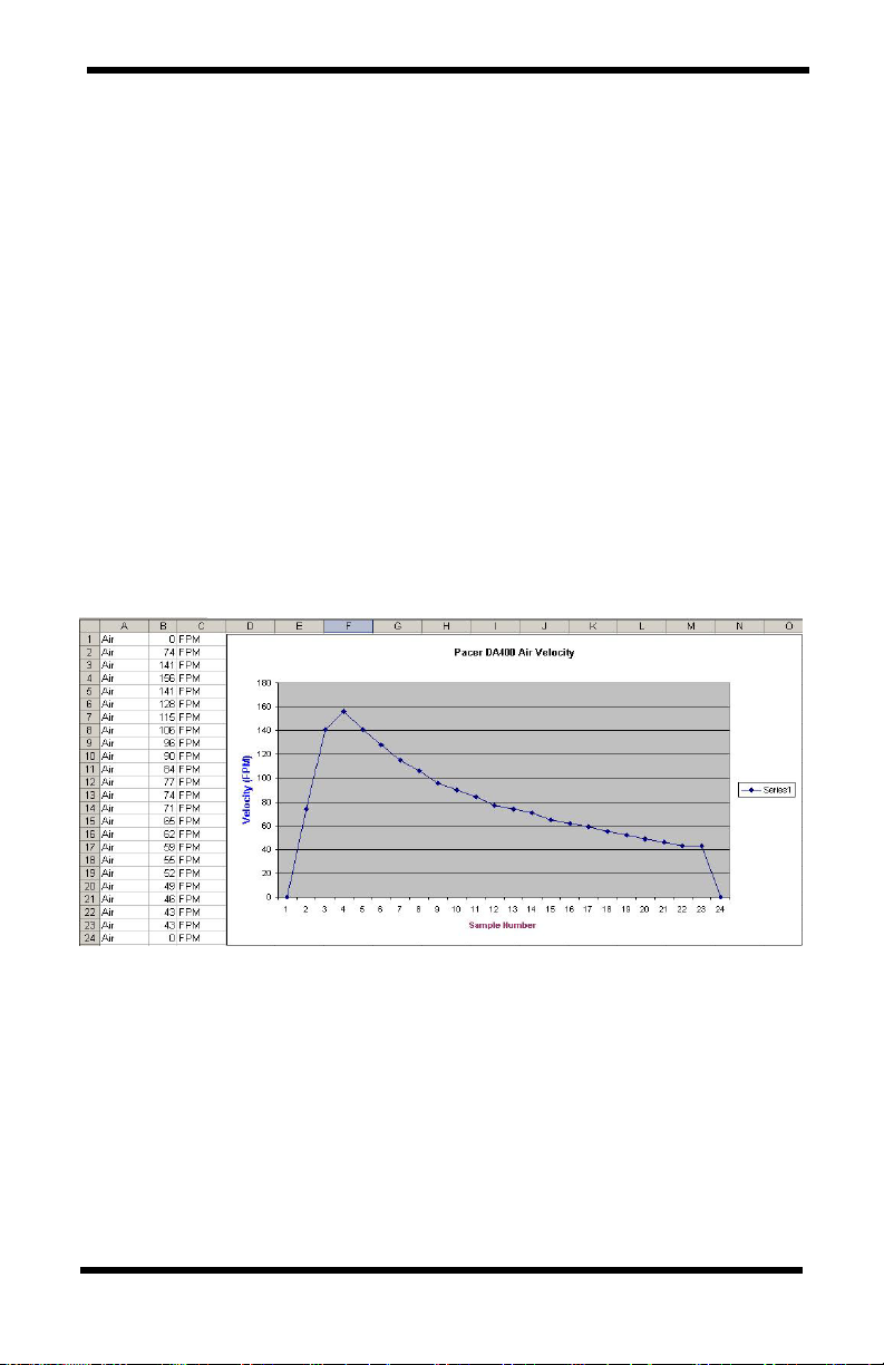
Exporting serial port instrument data from the Pacer Instrument to a spreadsheet
application such as Microsoft Excel or OpenOffice Calc allows the data to
graphed or recorded.
The simplest way to export the instrument data is to use a terminal emulator
program, like Parallax Serial Terminal, and either capture the serial data/text to a
file (menu selection) or to manually highlight, copy, and then paste the
instrument data into an editor such as Windows Notepad.
Once you have the instrument data in a file, save the file as a .CSV type (e.g.,
InstrumentData.csv).
Open the file in a spreadsheet application such as Microsoft Excel or
OpenOffice Calc. A graph of the data as shown below can now be generated.
M4750/1222
Page 22 of 24
Page 23

WARRANTY/DISCLAIMER
OMEGA ENGINEERING, INC. warrants this unit to be free of defects in materials and workmanship for a
period of
13 months
from date of purchase. OMEGA’s WARRANTY adds an additional one (1) month grace
period to the normal
one (1) year product warranty
to cover handling and shipping time. This ensures
that OMEG A’s customers receive maximum coverage on each product.
If the unit malfunctions, it must be returned to the factory for evaluation. OMEGA’s Customer Service
Department will issue an Authorized Return (AR) number immediately upon phone or written request.
Upon examination by OMEGA, if the unit is found to be defective, it will be repaired or replaced at no
charge. OMEGA’s WARRANTY does not apply to defects resulting from any action of the purchaser,
including but not limited to mishandling, improper interfacing, operation outside of design limits,
improper repair, or unauthorized modification. This WARRANTY is VOID if the unit shows evidence of
having been tampered with or shows evidence of having been damaged as a result of excessive corrosion;
or current, heat, moisture or vibration; improper specification; misapplication; misuse or other operating
conditions outside of OMEGA’s control. Components in which wear is not warranted, include but are not
limited to contact
points,
fuses, and triacs.
OMEGA is pleased to offer suggestions on the use of its various products. However, OMEGA
neither assumes responsibility for any omissions or errors nor assumes liability for any
damages that result from the use of its products in accordance with information provided by
OMEGA, either
verbal
or written. OMEGA warrants only that the
parts manufactured
by the
company will be as specified and free of defects. OMEGA MAKES NO OTHER WARRANTIES OR
REPRESENTATIONS OF ANY KIND WHATSOEVER, EXPRESSED OR IMPLIED, EXCEPT THAT OF
TITLE, AND ALL IMPLIED WARRANTIES INCLUDING ANY WARRANTY OF MERCHANTABILITY
AND FITNESS
FOR
A PARTICULAR PURPOSE ARE HEREBY DISCLAIMED.
LIMITATION
OF
LIABILITY: The remedies of purchaser set forth herein are exclusive, and the total liability of
OMEGA with respect to this order, whether based on contract, warranty, negligence,
indemnification, strict liability or otherwise, shall not exceed the purchase price of the
component upon which liability is based. In no event shall OMEGA be liable for consequential,
incidental or special damages.
CONDITIONS: Equipment sold by OMEGA is not intended to be used, nor
shall it be used:
(1) as a “Basic
Component” under 10 CFR 21 (NRC), used in or with any nuclear installation or activity; or (2) in medical
applications or used on humans. Should any Product(s) be used in or with any nuclear installation or
activity, medical application, used on humans, or misused in any way, OMEGA assumes no responsibility
as set forth in our
basic
WARRANTY/DISCLAIMER language, and, additionally,
purchaser
will indemnify
OMEGA and hold OMEGA harmless from any liability or damage whatsoever arising out of the use of the
Product(s) in such a manner.
RETURN REQUESTS/INQUIRIES
Direct all warranty and repair requests/inquiries to the OMEGA Customer Service Department. BEFORE
RETURNING ANY PRODUCT(S) TO OMEGA, PURCHASER MUST OBTAIN AN AUTHORIZED RETURN
(AR) NUMBER FROM OMEGA’S CUSTOMER SERVICE DEPARTMENT (IN ORDER TO AVOID
PROCESSING DELAYS). The assigned AR number should then be marked on the outside of the return
package and on any correspondence.
The purchaser is responsible for shipping charges, freight, insurance and proper packaging to prevent
breakage in transit.
FOR
WARRANTY
RETURNS, please have the
following information available BEFORE contacting
OMEGA:
1.
Purchase Order number under which the product
was PURCHASED,
2.
Model and serial number of the product under
warranty, and
3.
Repair
instructions and/or specific
problems
relative to the product.
FOR NON-WARRANTY REPAIRS, consult
OMEGA for current repair charges. Have
the following information available BEFORE
contacting OMEGA:
1.
Purchase Order number to cover the COST
of the repair,
2.
Model
and serial
number of the product, and
3.
Repair instructions and/or specific problems
relative to the product.
OMEGA’s policy is to make running changes, not model changes, whenever an improvement is possible. This affords
our customers the latest in technology and engineering.
OMEGA is a trademark of OMEGA ENGINEERING, INC.
© Copyright 2019 OMEGA ENGINEERING, INC. All rights reserved. This document may not be copied, photocopied,
reproduced, translated, or reduced to an y electronic medium or machine-readable fo rm, in whole or in part, witho ut the prior
written consent of OMEGA ENGINEERING, INC.
Page 23 of 24
M4750/1222
Page 24

Where Do I Find
Everything I Need for
Process Measurement
and Control?
OMEGA…Of
Course!
Shop
online at omega.com
TEMPERATURE
MU
Thermocouple,
RTD & Thermistor Probes, Connectors,
Panels & Assemblies
M
U
Wire: Thermocouple, RTD & Thermistor
MU
Calibrators
& Ice Point References
M
U
Recorders, Controllers & Process Monitors
M
U
Infrared Pyrometers
PRESSURE, STRAIN AND FORCE
MU
Transducers
& Strain Gages
MU
Load Cells
& Pressure Gages
M
U
Displacement Transducers
MU
Instrumentation & Accessories
FLOW/LEVEL
MU
Rotameters, Gas Mass Flowmeters & Flow Computers
MU
Air Velocity Indicators
MU
Turbine/Paddlewheel Systems
MU
Totalizers & Batch Controllers
pH/CONDUCTIVITY
MU
pH Electrodes, Testers & Accessories
M
U
Benchtop/Laboratory Meters
MU
Controllers, Calibrators, Simulators & Pumps
M
U
Industrial pH & Conductivity Equipment
DATA ACQUISITION
MU Communications
-Based Acquisition
Systems
MU Data Logging Systems
MU
Wireless Sensors, Transmitters, & Receivers
MU
Signal Conditioners
MU Data Acquisition Software
HEATERS
MU
Heating Cable
MU
Cartridge & Strip Heaters
MU
Immersion & Band Heaters
MU
Flexible Heaters
MU
Laboratory Heaters
ENVIRONMENTAL
MONITORING AND CONTROL
MU
Metering & Control Instrumentation
MU
Refractometers
MU
Pumps & Tubing
MU
Air, Soil & Water Monitors
MU
Industrial Water & Wastewater Treatment
MU
pH, Conductivity & Dissolved Oxygen Instruments
Page 24 of 24
M4750/1222
 Loading...