

Page 1
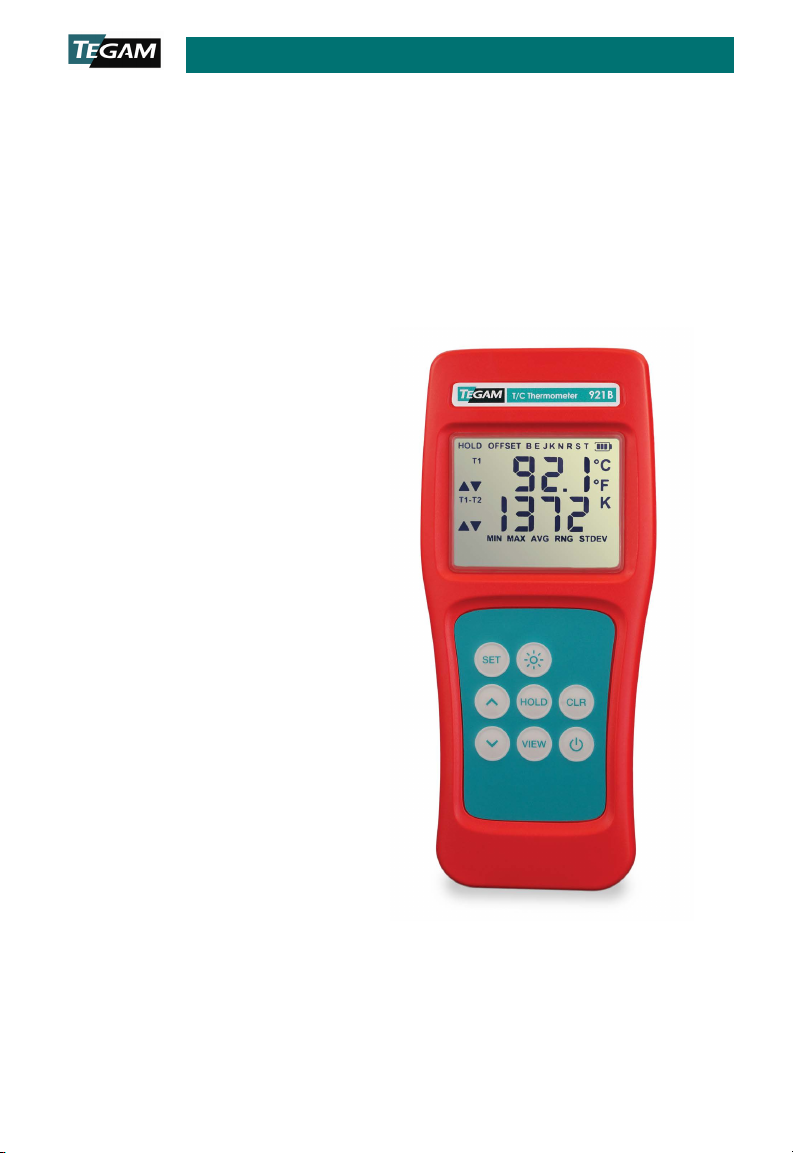
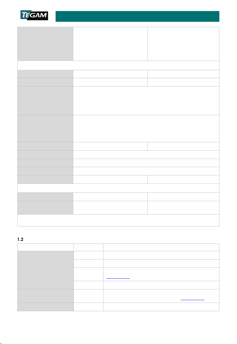
921B, 922B
I
THERMOMETERS
Models:
921B, 922B
Thermocouple Thermometers
Manual Part Number: 921B-900, Rev. A
Published Ap ril 2019, Geneva, OH
NTRINSICALLY SAFE THERMOCOUPLE
Operation
Manual
10 TEGAM WAY ● GENEVA, OHIO 44041 ● 440-466-6100 ● FAX 440-466-6110 ●
Page 2
Notices
death.
CAUTION denotes a hazard
the unit or other equipment.
measurements.
NOTICES
Copyright Notice
© TEGAM, Inc., 2019
No par t of th is ma nual ma y be re produ ce d
in any form or by any means (including
electronic storage and retrieval or
translation into a foreign language)
without prior agreement and written
consent from TEGAM, Inc. as governed by
United States and international copyright
laws.
This Manual
Part Number:
921B-900
Revision A, April 2019
Supersedes: No prior revision.
Published by:
TEGAM, Inc.
10 TEGAM Way
Geneva, OH 44041
Disclaimer and Manual Revisions:
THE MATERIAL CONTAINED IN THIS
OPERATION MANUAL, AND ANY
COMPUTER SOFTWARE ASSOCIATED
WITH THIS OPERATION MANUAL OR THE
PRODUCTS COVERED BY IT, ARE
PROVIDED AS IS, AND ARE SUBJECT TO
CHANGE, WITHOUT NOTICE, IN FUTURE
REVISIONS.
This Operation Manual was current at the
time of publication. However, TEGAM is
dedicated to a process of continual
product improvement, and the products
covered by this Operation Manual, and
any associated computer software, are
subject to periodic functional and design
updates. Please visit tegam.com for the
most current product documentation.
U.S. Government Rights
This computer software and/or technical
data is proprietary information developed
exclusively at private expense. Computer
software and technical data rights granted
to the federal government include only
those rights customarily provided to the
public, pursuant to FAR 12.211 (Technical
data) and FAR 12.212 (Computer
software) for the federal government, and
DFARS 252.227-7015 (Technical data –
Commercial items) and DFA RS 227-72023 (Rights in commercial computer
software or commercial computer
10 TEGAM WAY ● GENEVA, OHIO 44041 ● 440-466-6100 ● FAX 440-466-6110 ●
software documentation) for the
Department of Defense. Except as
explicitly permitted by the foregoing,
reproduction for non-governmental use of
the information or illustrations contained
in this computer software and technical
data is not permitted.
Compliance and Markings
(This section, Compliance and Markings,
is controlled and may only be changed
with approval of the Notified Body.)
Handheld Thermometer for Hazardous
Locations Only as to Intrinsic Safety
Safety Notice Symbols and Terms
Safety Notices denote hazards. They
indicate an operating procedure,
instruction, or practice that, if not
correctly performed or followed, could
result in damage to equipment, or injury
or death to personnel. Do not proceed
beyond a Safety Notice until all conditions
and instructions are fully understood and
complied with.
Safety Notice Symbols:
ii
0539 II 1G
Ex ia IIB T4 Ga
Class I, Division 1, Group C
Class I, Zone 0 AEx ia IIB T4
Zone 0 Ex ia IIB T4 Ga
DEMKO 19 ATEX 1970 Rev. 0
IECEx UL 19.0010
-20 °C ≤ Ta ≤ +50 °C
WARNING denotes an
WARNING
CAUTION
imminent hazard that could
result in injury to personnel or
that could result in damage to
REMINDER denotes important
information about instrument
functions, menus, and
and D, T4
Page 3
Table of Contents
TABLE OF CONTENTS
1. Instrument Description .......................................................................................... 1-1
Specifications ................................................................................................ 1-1
Optional Accessories and Ordering Information .................................................. 1-3
TEGAM Family of Thermometers....................................................................... 1-4
2. Preparation for Use ................................................................................................ 2-1
General Information ....................................................................................... 2-1
Feature Overview ........................................................................................... 2-1
Agency Compliance and Safety Warnings .......................................................... 2-2
Safety Notices and Information ........................................................................ 2-3
Use of Certified Thermocouple Probes ............................................................... 2-5
Unpacking and Inspection ............................................................................... 2-6
Battery Installation and Replacement................................................................ 2-6
Making Your First Temperature Measurement .................................................... 2-7
3. Operating Instructions ........................................................................................... 3-1
Keypad Functions ........................................................................................... 3-1
LCD Display ................................................................................................... 3-1
Setup Menu ................................................................................................... 3-3
View Modes and Statistics ............................................................................... 3-4
Auto-Power Off .............................................................................................. 3-5
Backlight and Backlight Timeout ....................................................................... 3-6
Hold Function ................................................................................................ 3-6
Trend Indicators ............................................................................................. 3-6
Battery Indicator ............................................................................................ 3-6
Probe Offset .................................................................................................. 3-7
Open Wire Detection On/Off ............................................................................ 3-8
Clear Function................................................................................................ 3-9
Invalid Measurement Indications ...................................................................... 3-9
Resolution and Rounding Functions................................................................... 3-9
4. Service Information ............................................................................................... 4-1
Inspection and Cleaning .................................................................................. 4-1
Calibration ..................................................................................................... 4-1
4.2.1 Verification Procedure ................................................................................. 4-1
4.2.2 Alignment Procedure ................................................................................... 4-2
Troubleshooting ............................................................................................. 4-6
Diagnostic Routines and Error Codes ................................................................ 4-7
Memory Sterilization ....................................................................................... 4-7
Preparation for Calibration or Repair Service ...................................................... 4-8
Expedite Repair & Calibration Form .................................................................. 4-9
Warranty ............................................................................................................. 4-10
Warranty Limitations............................................................................................. 4-10
Statement of Calibration ....................................................................................... 4-10
A. Required Equipment ............................................................................................... A-i
B. Expanded Instrument Uncertainties .......................................................................... B-i
C. Instrument Verification Data Sheet ........................................................................... C-i
10 TEGAM WAY ● GENEVA, OHIO 44041 ● 440-466-6100 ● FAX 440-466-6110 ●
iii
Page 4
Instrument Description
G
:
Basic Accuracy
±(0.04% |rdg| + 0.3 °C)1
Conformity
ITS-90
Temperature
K
-200 to 1372
-328 to 2502
73 to 1645
J
-210 to 1200
-346 to 2192
63 to 1473
T
-250 to 400
-418 to 752
23 to 673
E
-250 to 1000
-418 to 1832
23 to 1273
B
600 to 1820
1112 to 3308
873 to 2093
N
-250 to 1300
-418 to 2372
23 to 1573
R
0 to 1767
32 to 3213
273 to 2040
S
0 to 1767
32 to 3213
273 to 2040
Connector Type
One (1) Mini-TC (921B)
Two (2) Mini-TC (922B)
Probe Zero Function
Resolution 0.1 °C/°F/K
Four (4) digit LCD, with Temperature, Units, Function, Trend,
Display Backlight
Four (4) LED Backlight with 30-second timeout
Display Resolution
0.1 ° < 1000 °
1 ° ≥ 1000 °
Reading Rate
3 / Second for Readings and Trend Indicators
Battery Type
3 AA (IEC LR6, ANSI 15) Alkaline
Battery Life
2000 Hours Typical
Battery Indicator
Four (4) Stage Battery Charge Indicator
Minimum Reading
Reading Range
Keypad
Eight (8) momentary switches with audible and tactile feedback
Clock
Elapsed Statistics Run Time
Instrument retains last selected:
Input Current
±50 nA
Maximum Common
42 V peak to earth
1 V p-p between T1 and T2
1. INSTRUMENT DESCRIPTION
Specifications
ENERAL SPECIFICATIONS
Ranges
Display
Statistics
°C °F K
Polarity, Battery, and Decimal Indicators
Maximum Reading
Average Reading
Standard Deviation
T1–T2 (922B only)
Power Cycle
Configuration
Retention
10 TEGAM WAY ● GENEVA, OHIO 44041 ● 440-466-6100 ● FAX 440-466-6110 ●
- Sensor Type
- Temperature Unit
- Offset Values
1-1
Page 5
Instrument Description
Mode Voltage
Compliance
EMC (2014/30/EU) / RoHS2 (2011/65/EU) / LVD (2014/35/EU)
ESD
IEC 61000-4 2:2009, Performance criterion B
10 TEGAM WAY ● GENEVA, OHIO 44041 ● 440-466-6100 ● FAX 440-466-6110 ●
1-2
Page 6
Instrument Description
EN 55022:2010+A1:2015,
E
:
Standards
MIL-PRF-28800F, Class 2
Operating Temp
-20 °C to +50 °C
-4 °F to +122 °F
For specification variances due to ambient operating
<10 °C (50 °F): Non-condensing
Altitude
0 m to 4600 m
0 ft to 15 092 ft
Vibration
Random 10 Hz to 500 Hz, 0.03 g2/Hz
Shock
30g Half Sine
Drop
4 Drops from 1 m to Concrete
Storage Temp
-40 °C to +71 °C
-40 °F to +159 °F
P
:
Dimensions
(193 X 84 X 28) mm
(7.6 X 3.3 X 1.1) in
Weight (incl.
1
For complete instrument accuracies, see the Expanded Instrument Uncertainty charts in Appendix B of
P
M
D
921-910
Tilt Stand/Magnet/Hanger Factory Installed
921-912
Tilt Stand/Magnet/Hanger User Installed
See TEGAM Temperature Probe Selection Guide at
921B-900
Operation Manual
Chinese, Dutch, French, German, Japanese,
Manual Translations
Calibration with Statement of Traceability
Class A; EN 61000-4
EMC
NVIRONMENT
Temperature
Coefficient
Humidity
HYSICAL CHARACTERISTICS
Batteries)
3:2006+A2:2010, 10 V/m
(80 MHz to 1 GHz), 3 V/m (1.4
GHz to 2 GHz), 1 V/m (2 GHz
to 2.7 GHz)
temperature, see the Expanded Instrument Uncertainty charts
in Appendix
temperatures not shown in Appendix B, accuracies shall be
interpolated linearly.
10 to 30 °C (50 to 86 °F): 5 to 95 % RH
30 to 40 °C (86 to 104 °F): 5 to 85 % RH
40 to 50 °C (104 to 122 °F): 5 to 60 % RH
921B: 300.9 g (10.6 oz) 922B: 303.2 g (10.7 oz)
MIL-PRF-28800F, Class 2
EN 61326-1:2013
B of this manual. For ambient operating
this manual .
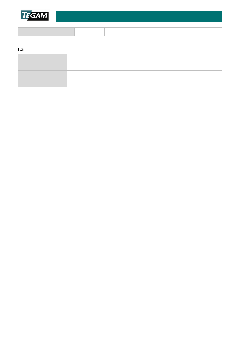
Optional Accessories and Ordering Information
RODUCT
Accessories
Printed Manual
10 TEGAM WAY ● GENEVA, OHIO 44041 ● 440-466-6100 ● FAX 440-466-6110 ●
ODEL
ESCRIPTION
tegam.com for available temperature probes
Korean, and Spanish (download at tegam.com)
1-3
Page 7
Instrument Description
Service Options
911B
Thermocouple Thermometer, Single Input
912B
Thermocouple Thermometer, Dual Input
931B
Data Thermometer, Single Input
932B
Data Thermometer, Dual Input
TEGAM Family of Thermometers
Thermocouple
Thermometers
Data
Thermometers
10 TEGAM WAY ● GENEVA, OHIO 44041 ● 440-466-6100 ● FAX 440-466-6110 ●
1-4
Page 8

Preparation for Use
2. PREPARATION FOR USE
General Information
The TEGAM 921B and 922B Thermocouple Thermometers are high-accuracy handheld digital
thermometers that provide accurate temperature readings in a wide range of manufacturing
and service applications. These full-featured, durable, and versatile instruments simplify the
process of temperature measurement through the intuitive user-interface. They are
compatible with the four most popular NIST traceable thermocouple types: E, J, K, T, B, N, R
and S.
Feature Overview
• Keypad with audible and tactile feedback
• 2000-hour battery life
• Four (4) digit dual LCD with LED Backlight
• Eight (8) NIST-traceable thermocouple types: E, J, K, T, B, N, R and S
• Comprehensive real-time statistics: MIN, MAX, AVG, RNG, STDEV, and T1-T2
• Easy to clean
• Probe offset function to minimize probe error
• 0.1 ° / 1 ° display resolution
• °F, °C, and K temperature units
• Reading HOLD mode
• Conforms to ITS-90 thermocouple tables
• Durable: Meets MIL-PRF-28800F, Class 2 requirements
• Optional Tilt Stand/Magnet/Hanger
• User-friendly operation
• Retains measurement parameters, even when turned off
• Self-diagnostic routine to identify fault condit ions
• Low battery and open sensor indications
1
2
1
Typical battery life under normal use conditions in laboratory environment. Continuous or
repeated use of features such as the backlight, or use or storage at high or low temperature
extremes may reduce battery life.
2
T1-T2 is available on model 922B only.
2-1
10 TEGAM WAY ● GENEVA, OHIO 44041 ● 440-466-6100 ● FAX 440-466-6110 ●
Page 9
Preparation for Use
Les batteries font partie du système de
pourrait affecter la sécurité intrinsèque.
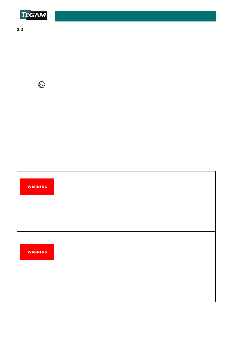
Agency Compliance and Safety Warnings
(This section, Agency Compliance and Safety Warnings, is co n tro l le d an d ma y only be ch ang e d
with approval of the Notified Body.)
Ex Hazardous Safety Information
This instrument is intrinsically safe. WARNING: substitution of components may impair
intrinsic safety. This instrument complies with Agency Standards and is listed as:
• II 1G
• Ex ia IIB T4 Ga
• Class I, Division 1, Group C and D, T4
• Class I, Zone 0 AEx ia IIB T4
• Zone 0 Ex ia IIB T4 Ga
This operation manual contains safety information and warnings that must be observed for safe
operation under the conditions described. Failure to comply with the information and
instructions can have serious consequences. Read this manual in its entirety before using the
instrument.
To reduce the ignition risk of a flammable or
WARNING –
EXPLOSION HAZARD
explosive atmosphere, batteries must be
changed in a location known to be nonhazardous.
AVERTISSEMENT – RISQUE
D’EXPLOSION
WARNING –
EXPLOSION HAZARD
AVERTISSEMENT – RISQUE
D’EXPLOSION
10 TEGAM WAY ● GENEVA, OHIO 44041 ● 440-466-6100 ● FAX 440-466-6110 ●
Afin de réduire le risque d’allumage dans
une atmosphère inflammable ou explosive,
les batteries doivent être remplacées dans
un endroit connu pour être non dangereux.
Batteries are part of the intrinsically safe
system. Use only the specific battery type,
manufacturer, and manufacture’s part listed
in the Operation Manual. Use of other
batteries could impair intrinsic safety.
Batteries may not be mixed.
sécurité intrinsèque. Utiliser uniquement le
type et le modèle spécifique de batterie et
les pièces du fabricant mentionnées dans le
manuel. L’utilisation d’autres batteries
2-2
Page 10

Preparation for Use
Utiliser uniquement les types de sondes
sécurité intrinsèque.
WARNING –
EXPLOSION HAZARD
AVERTISSEMENT – RISQUE
D’EXPLOSION
Safety Notices and Information
To prevent personal injury while in Ex Hazardous areas, follow the guidelines below:
• NEVER SERVICE THIS UNIT IN AN Ex HAZARDOUS AREA.
• Batteries are part of the intrinsically safe system. Use only the specific battery type
and manufacturers listed in the Operation Manual. Use of other batteries could
impair intrinsic safety. Do not mix batteries of different manufactures. Do not mix
fresh batteries with old batteries.
• Do not take spare batteries into an Ex Hazardous area.
• To reduce the risk of ignition of a flammable or explosive atmosphere, batteries
must be changed only in a location known to be Non Hazardous.
• Never open the instrument while in an Ex Hazardous area.
• Never store the instrument with batteries installed in an Ex Hazardous area.
• Never use the instrument with the battery cover off.
Use only the probe types as listed in the
manual. Use of other probe types could
impair intrinsic safety.
spécifiés dans le manuel. L’utilisation
d’autres types de sondes pourrait affecter la
• Do not put batteries into bags designed to protect parts from electrostatic discharge
(ESD). These bags are specially designed with metal shielding which can short
circuit a battery.
• Use only approved accessories with this product in Ex Hazardous areas.
• Use this product only as specified or protection provided by the instrument could be
compromised.
• Never touch the probe(s) to a voltage source.
• Check the integrity of the case prior to using the instrument in an Ex Hazardous
area. Look for any compromises like cracks or missing plastic.
• Always comply with all safety codes.
10 TEGAM WAY ● GENEVA, OHIO 44041 ● 440-466-6100 ● FAX 440-466-6110 ●
2-3
Page 11

Preparation for Use
case removed.
expose u sers to el evated potentials.
Never use this instrument or any temperature probe or sensor inside a microwave oven.
damage or personal injury could result from exceeding a probe’s maximum temperature rating.
Safety Notices and Information
Read this Operation Manual thoroughly before using the instrument to become familiar with its
Visually inspect instrument before using. Do not use if unit appears damaged or with any part of the
MAINTENANCE INSTRUCTIONS WITHIN THIS MANUAL ARE FOR USE BY QUALIFIED SERVICE PERSONNEL
ONLY. DO NOT ATTEMPT TO SERVICE THIS UNIT UNLESS YOU ARE QUALIFIED TO DO SO.
Disconnect all temperature probes and turn the unit off before removing the battery cov er.
Never connect thermocouple leads to any source where more than 42 Volts (peak) could exist
between the lead and ground. If it is necessary to make measurements of an object at elevated
electrical potential, the user is responsible for obtaining and properly using a probe that provides adequate
insulation between the surface with elevated potential and the thermocouple wiring.
Always disconnect probe leads before opening the battery door or the instrument housing.
Internal circuits can present a shock hazard if leads are connected to a source of elevated potential.
Do not use this instrument if the housing, probe wiring, probe, or probe handle are damaged or
distorted. Housings and wi re insu lati on are part of the personnel prote ction system, and if damaged could
Never change batteries, in an environment where explosive or flammable vapors or dust
suspensions may exist.
Do not attempt to recharge alkaline batteries.
Do not put batteries into bags designed to protect parts from electrostatic discharge (ESD).
These bags are specially designed with metal shielding which can short circuit a battery.
Do not expose batteries to extreme heat or fire. Observe all regional laws and regulations when
disposing batteries.
These instruments have a temperature classification of T4 or 135 °C maximum surface
temperature. Consideration should be given when using approved thermocouple probes in sensing
environments exceeding this temperature class. The probe sheath and/or tip can be at a temperature which
may cause auto ignition in an explosive hazardous location.
operations and capabilities.
WARNING
SHOCK HAZARD
EXPLOSION HAZARD
BURN HAZARD
Do not touch a temperature probe sheath that has been exposed to toxic substances or
extremely high or low temperatures.
Do not attempt to measure temperatures beyond the range of the temperature probe. Probe
Safety Notices and Information continued on next page . . . .
2-4
10 TEGAM WAY ● GENEVA, OHIO 44041 ● 440-466-6100 ● FAX 440-466-6110 ●
Page 12
Preparation for Use
RISK OF INSTRUMENT DAMAGE
care to avoid static discharge when handling the instrument or connected probes.
Do not use when AC or DC voltages in excess of 1V exist between thermocouple channels (on
instruments with more than one channel). Excessive voltage could result in an incorrect reading, or
in more extreme cases, a blown fuse that will result in incorrect readings and need for repair.
Only replace batteries with size AA (IEC LR6, ANSI 15). Observe proper polarity when installing
batteries. Do not mix old and new batteries.
Do not apply voltages across thermocou ple leads in excess of normal thermocouple voltage for
the selected range. Excessive input voltage could result in blown fuse, component damage, or fire.
Application of excessive voltage is not covered by the warranty.
Avoid making sharp bends in probe or sensor lead wires. Bending lead wires at sharp angles can
damage the wire and cause probe failure.
When using both thermometer inputs and a voltage differential exists between the two
measurement points, at least one probe should be electrically insulated. If not, a ground-loop
current can flow through the thermocouple leads causing measurement error or instrument damage.
Static discharge through a connected temperature probe may cause instrument damage. Use
RISK OF INCORRECT READING
CAUTION
Use of Certified Thermocouple Probes
(This section, Use of Certified Thermocouple Probes, is controlled and may only be changed
with approval of the Notified Body.)
Use only TEGAM IS9 Series of thermocouple probes, with either the 921B or 922B, in
potentially hazardous locations. Use of any other combination probe and cable, including
thermocouple extension wiring, invalidates the type certification and may cause auto ignition in
an explosive hazardous location.
Standard, two-wired thermocouple leads with welded bead ends may be used, limited to a
three (3) meter length.
2-5
10 TEGAM WAY ● GENEVA, OHIO 44041 ● 440-466-6100 ● FAX 440-466-6110 ●
Page 13
Preparation for Use
instrument.
to the instrument.
Unpacking and Inspection
Each instrument is electrically and mechanically inspected before shipment. Upon receiving
your new TEGAM Thermocouple Thermometer, unpack all items from the shipping container
and check for any obvious damage that may have occurred during transit. Use the original
packing materials if reshipment is necessary.
If any dents, broken, or loose parts are seen, do not use the equipment. Notify TEGAM
immediately.
Check that all items are present. If any items are missing, notify TEGAM immediately.
The following items are included with every new instrument:
• One (1) Thermocouple Thermometer;
• One (1) Quick Start;
• Statement of Traceability;
• Three (3) AA, 1.5 V batteries;
• Optional accessories (if purchased).
Battery Installation and Replacem ent
(This section, Battery Installation and Replacement, is controlled and may only be changed
with approval of the Notified Body.)
Three (3) AA 1.5 V batteries are supplied with the instrument, but not installed. Read the
following battery replacement instructions before attempting to install or remove the
batteries.
WARNING Always change the product’s batteries outside Ex Hazardous areas.
CAUTION
CAUTION
CAUTION
Always turn the instrument off and disconnect any input connections before replacing
the batteries. Re-install the battery compartment cover before resuming use of the
The battery compartment is sealed with a rubber gasket. Use care to not damage the
gasket when removing or installing the battery compartment cover.
Remove the batteries when storing the instrument for an extended period of time or
in a high temperature environment to prevent battery leakage and possible damage
All measurement parameters may be reset to factory default if batteries are removed while
the instrument is powered on. Always turn the instrument off before changing batteries.
To install or replace batteries:
Required Tools: Phillips Head Screwdriver
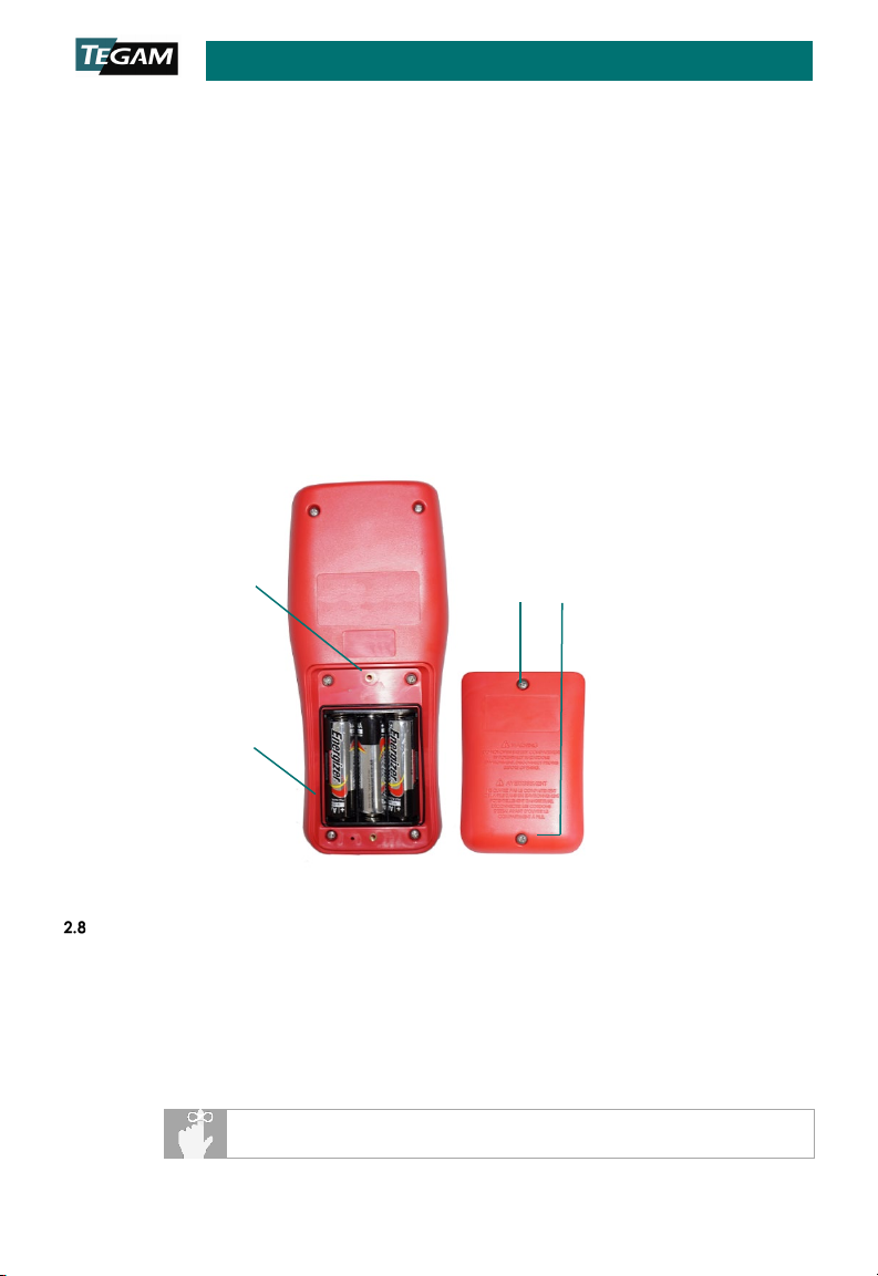
1. Identify the battery compartment located on the back of the instrument (see
Figure
1 below);
2. Remove the two (2) battery compartment retaining screws;
3. Remove the battery compartment cover;
10 TEGAM WAY ● GENEVA, OHIO 44041 ● 440-466-6100 ● FAX 440-466-6110 ●
2-6
Page 14
Preparation for Use
Retaining Screws
Battery
Gasket
4. If present, carefully remove old batteries being careful to not damage the battery
contacts;
5. Use only Zinc-Manganese Dioxide or Alkaline-Manganese Dioxide AA cells that
have been tested by a nationally recognized laboratory to meet the requirements
of UL 60079-11, Sixth Edition. Use of any other battery will invalidate the Type
Certificate and create a hazardous condition. The only batteries that TEGAM, Inc.
has secured such testing, which are approved for use in either a 921B or 922B, are
listed on the Type Certificate. They are:
• Energizer E91
• Duracell MN1500
6. Observing proper polarity, install three (3) new, AA alkaline (IEC LR6, ANSI 15)
batteries;
7. Re-install the battery cover and two (2) retaining screws;
8. At initial power on after battery replacement, allow approximately 30 seconds for
instrument to stabilize.
Compartment
Figure 1: Battery Installation
Making Your First Temperature Measurement
TEGAM’s 900 Series Thermocouple Thermometers are designed for easy operation, while still
providing a feature-rich experience via the intuitive user interface.
To get started making temperature measurements right away, follow these steps:
1. Perform Section 2.7, Battery Installation and Replacement;
2. Connect a compatible temperature probe to the Channel 1 and/or Channel 2 input
connector located at the top of the instrument;
To ensure best measurement accuracy, allow several minutes for the
thermocouple probe and connector to thermally stabilize after
10 TEGAM WAY ● GENEVA, OHIO 44041 ● 440-466-6100 ● FAX 440-466-6110 ●
2-7
Page 15

Preparation for Use
connection to the instrument.
3. The instrument will immediately display a temperature measurement for the
connected channels. However, to ensure valid and best accuracy measurements,
continue to Step 4 below;
4. Set the desired measurement parameters as follows:
a. Enter the Setup Menu by pressing , hold the key down for
approximately 1.5 seconds, and then release it;
b. The active thermocouple type is flashing on the display. Use to
select the thermocouple type of the connected temperature probe (E, J,
K, T, B, N, R, or S);
c. Momentarily (do not hold) press to save your selection and move to
the next parameter;
d. The active temperature unit is flashing on the display. Use to
select the desired temperature unit (°C, °F, or K);
e. Momentarily press to save your selection and move to the next
parameter;
f. Channel 1 probe offset value is flashing on the display. If the
temperature probe’s offset value is known, press to set the
Channel 1 probe offset to the probe’s offset value. See Section 3.10,
Probe Offset, for more information.
g. Momentarily press to save your selection and move to Channel 2
probe offset (if equipped);
h. If desired, repeat Step (f) above for Channel 2;
i. Momentarily press to save your selection and exit the setup
menu.
Congratulations! You’re now ready to make accurate and reliable temperature
measurements, wherever and whenever you may need to.
We know you are eager to begin using your new thermometer, but this overview is just the
beginning. Please take a moment to familiarize yourself with this Operation Manual to learn
about all the features and benefits of your new TEGAM Thermocouple Thermometer.
10 TEGAM WAY ● GENEVA, OHIO 44041 ● 440-466-6100 ● FAX 440-466-6110 ●
2-8
Page 16
Operating Instructions
While in Setup Menu, save current value
and step to next parameter
While in Calibration mode and when pressed simultaneously for 1.5
seconds, resets active calibration factor to default.
3. OPERATING INSTRUCTIONS
Keypad Functions
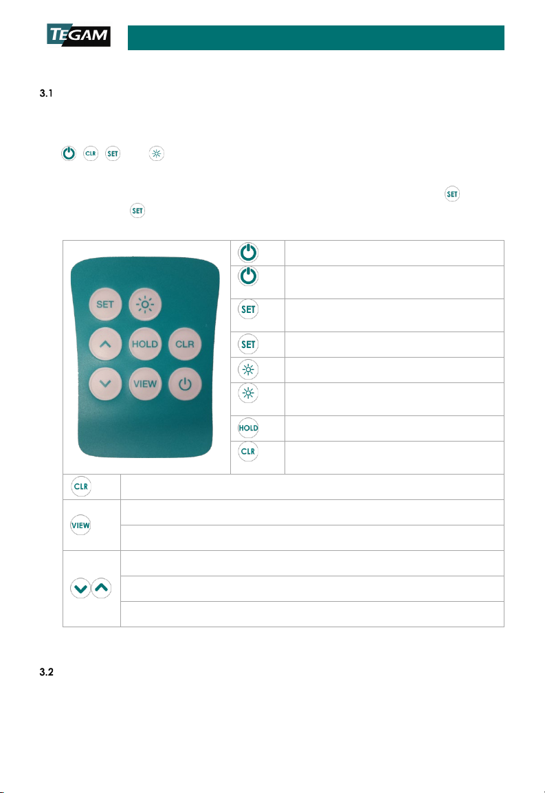
The instrument keypad is an eight (8) key, sealed membrane keypad. Each key provides
audible and tactile user feedback when pressed. Key functions are described in Figure 2
below.
The , , , and keys have multiple functions which can be accessed by
momentarily pressing the key, or alternatively, by pressing and holding the key for
approximately 1.5 seconds. Throughout this Operation Manual, the press and hold sequence
is indicated by the key designator followed by the subscript (1.5s). For instance,
indicates that the key should be pressed and held for 1.5 seconds, then released to
access the desired function.
Power instrument ON or OFF
Disable auto-power OFF while instrument
(1.5s)
is on
(1.5s)
(1.5s)
(1.5s)
(1.5s)
While in Setup Menu, discard all unsaved changes and exit menu
Cycle through view modes and statistics
While in Setup Menu, save changes and exit menu
While in Setup Menu, advance or reverse selected setting
While viewing saved data, advance or reverse displayed measurement
Enter instrument Setup Menu
Toggle display backlight
Disable backlight 30-second timeout
Hold currently displayed measurement
Reset all statistics currently stored in
memory
Figure 2: Keypad Button Functional Description
LCD Display
The display is a large, easy to read, dual LCD display, with an LED backlight for clear
viewing in low-light conditions. It simultaneously displays temperature measurements for
10 TEGAM WAY ● GENEVA, OHIO 44041 ● 440-466-6100 ● FAX 440-466-6110 ●
3-1
Page 17
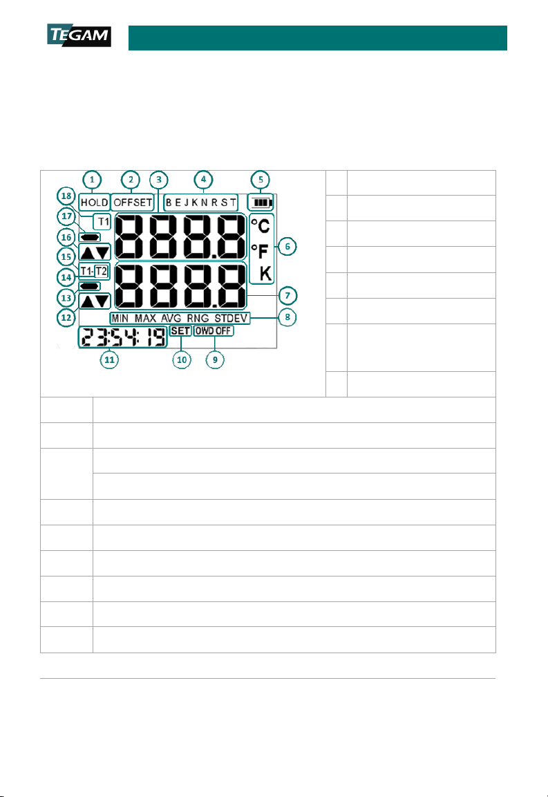
Operating Instructions
T1 and/or T2 OFFSET is
active1
Channel 1 temperature
measurement
type
Channel 2 temperature
active statistic result
Channel 1 and Channel 2, current thermocouple type and temperature unit, trend indicators
for both Channel 1 and Channel 2, and a battery voltage indicator.
In Statistics View, the display substitutes the Channel 2 temperature measurement with the
active statistic result and displays an active statistic mode indicator and the elapsed time of
the current statistic session. See Figure 3 below for further description of each display
indicator.
1 HOLD function is active
2
3
The active thermocouple
4
5 Remaining battery life
6 Active temperature unit
measurement2 ,T1-T2
7
measurement result
8 Active statistic
2
, or
9 Open Wire Detection Off
10 Setup Menu active
11 When viewing statistics, time elapsed since start of statistics collection
12 Channel 2 trend indicators2
13 Channel 2 minus indicator
14 Channel 2 indicator2
15 T1-T2 temperature measurement indicator2
16 Channel 1 trend indicators
17 Channel 1 minus indicator
18 Channel 1 indicator
1
T2 Probe Offset available on model 922B only.
2
Models 922B only.
10 TEGAM WAY ● GENEVA, OHIO 44041 ● 440-466-6100 ● FAX 440-466-6110 ●
Figure 3: LCD Display Description
3-2
Page 18
Operating Instructions
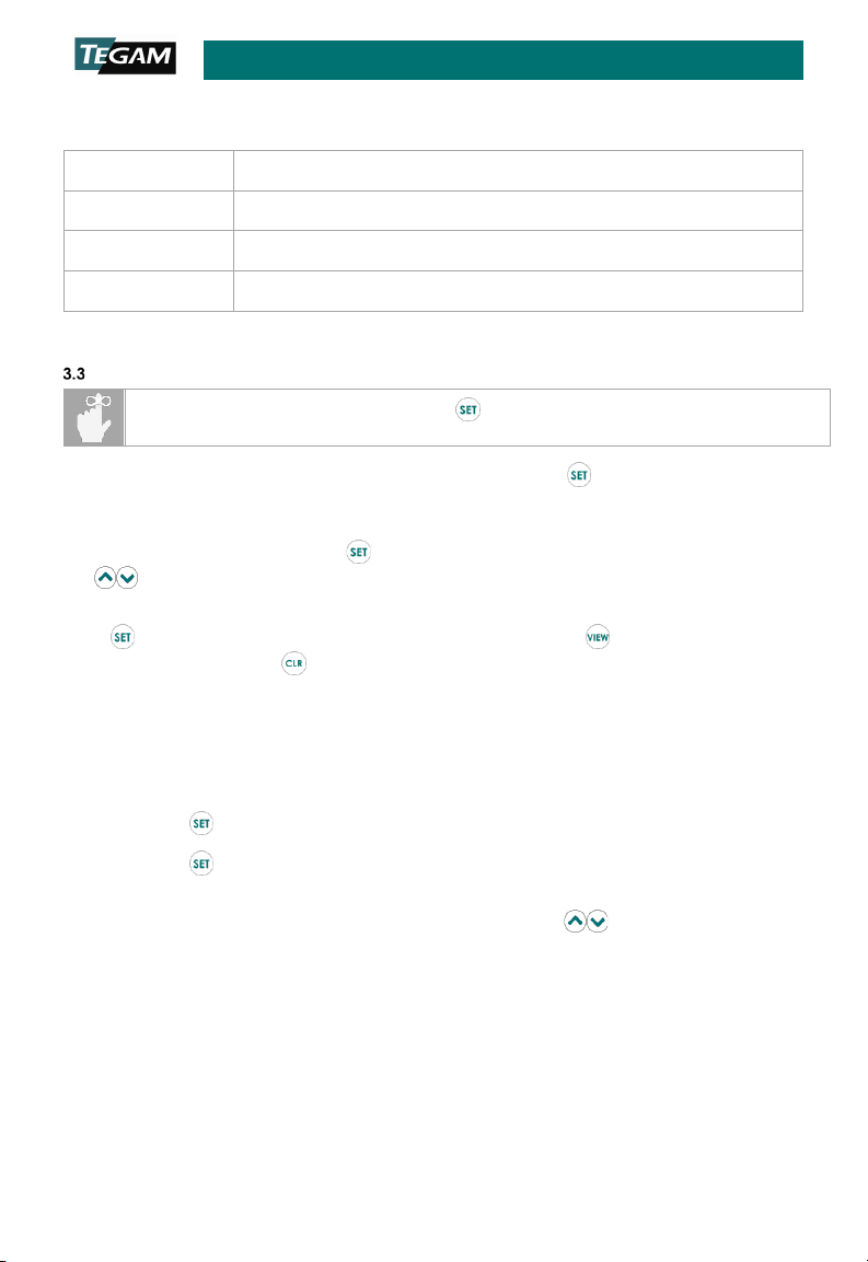
Over range: The applied temperature is greater than the maximum
temperature for the selected thermocouple type
Under range: The applied temperature is less than the minimum
temperature for the selected thermocouple type
The LCD can display error information about the current measurement, as shown in Figure
4.
ISPLAY DESCRIPTION
D
OPEn No thermocouple probe is connected or making connection
-Or-
-Ur-
Figure 4: LCD Error Indications
Setup Menu
Key designators followed by (1.5s), e.g.
pressed and held for 1.5 seconds, then released to access the desired function.
(1.5s)
, indicate that the key should be
Measurement settings are configured in the Setup Menu. Press
Menu. The SET annunciator will appear at the bottom of the display and the currently
selected thermocouple type will begin to flash.
From within the Setup Menu, press to step through the user-definable parameters and
the keys to advance or reverse the selected value for the active parameter. The active
parameter value will flash on the display.
Press to save a setting and step to the next parameter. Press to save a setting and
exit the Setup Menu. Press to disregard unsaved changes and exit the Setup Menu. If no
key is pressed for 10 seconds, the current configuration is saved, and the instrument will
exit the Setup Menu.
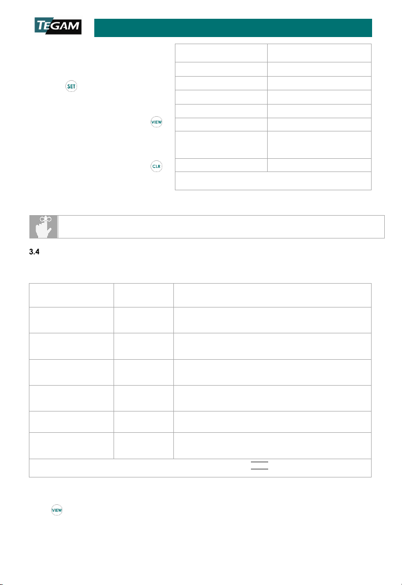
Figure 5 below lists the user-definable parameters and the available values for each
parameter.
To set a parameter value:
1. Press
2. Press to cycle through parameters as shown in Figure
parameter is reached;
3. To change the value of the current parameter, press ;
(1.5s)
to enter the Setup Menu;
(1.5s)
to access the Setup
5 until the desired
10 TEGAM WAY ● GENEVA, OHIO 44041 ● 440-466-6100 ● FAX 440-466-6110 ●
3-3
Page 19
Operating Instructions
D
INDICA TOR
Current Channel 1 measurement – current
Channel 2 measurement
Minimum temperature recorded during
current session
Maximum temperature recorded during
current session
Average of all temperatures recorded during
current session
Standard
Deviation
Standard deviation of all temperatures
recorded during the current session1.
4. To save the current
parameter value and cycle
to the next parameter,
press
(1.5s)
;
5. To save the current
parameter value and exit
the Setup Menu, press ;
6. To disregard changes
made to the current
parameter value and exit
the Setup Menu, press .
PARAMETER AVAILABLE VALUES
Thermocouple Type E, J, K, T
Temperature Units °C, °F, K
T1 Probe Offset ±0.1 ° increments
T2 Probe Offset1 ±0.1 ° increments
Open Wire Detection ON, OFF
Resolution and
Rounding functions
trnd ON, OFF
1
T2 Probe Offset available on model 922B only.
rndG, Auto, CEIL, nOrL,
trnC
Figure 5: Setup Menu Parameters and Values
If no key is pressed for 10 seconds, the instrument will save the current configuration
and exit the Setup Menu.
View Modes and Statistics
The instrument features multiple view modes including a variety of real-time statistics, all
available at the touch of a button. Figure 6 below describes each view mode.
VIEW MODE
ISPLAY
DESCRIPTION
T1–T2 T1-T2
Minimum MIN
Maximum MAX
Average AVG
Range RNG Maximum - Minimum
STDEV
2
∑
1
Standard Deviation is calculated using the population formula: =
(−µ)
�
Figure 6: View Modes and Statistics
Press to change view modes. For each mode, the active measurement or statistic result
is displayed on the second line of the display.
10 TEGAM WAY ● GENEVA, OHIO 44041 ● 440-466-6100 ● FAX 440-466-6110 ●
3-4
Page 20
Operating Instructions
results and initiate a new statistics session.
M
C
S
The T1-T2 view mode displays the current Channel 1 measurement minus the current
Channel 2 measurement. The display indicates T1-T2 at the left side of the display. If either
channel is not connected to a probe, or the current measurement on either channel is overor under-range, T1-T2 view mode is not ava ilable.
When viewing statistics, the active statistic is indicated directly below the result. The
elapsed time of the current statistics session is displayed in the lower-left corner of the
display.
Statistics are calculated continuously, beginning when the instrument is powered on or when
(1.5s)
is pressed. To pause statistics collection temporarily, press . To resume statistics
collection, press again.
It is important to note that changing parameter values or temperature probes will invalidate
the current statistics session. When using statistics, always begin by pressing
delete existing statistics data and initiate a new statistics session.
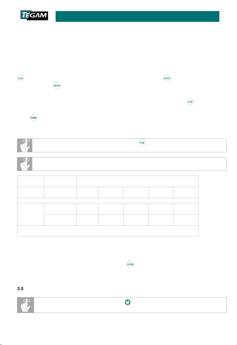
Press to step through the available statistics. Statistics are displayed in the order shown
in Figure 7 below. For dual-channel models, the LCD T1 or T2 indicators are lit to identify the
channel’s statistics currently being displayed.
(1.5s)
to
When using statistics, always begin by pressing
The first line of the display indicates the current Channel 1 temperature, regardless of
which view mode or channel’s statistic is currently displayed.
ODEL
921B T1 MIN MAX AVG RNG STDEV
922B
HANNEL
T1 MIN MAX AVG RNG STDEV
T2 MIN MAX AVG RNG STDEV
TATISTIC VIEW SEQUENCE
(1.5s)
to clear existing statistics
Figure 7: Statistics Sequence
If the instrument records invalid measurement data during the statistics session such as an
over-range, under-range, or open input value, ———— will be displayed for each affected
statistic result.
To return to the active measurement mode, press repeatedly to step through the
remaining view modes, or cycle power.
Auto-Power Off
3-5
(1.5s)
, indicate that the key should be
Key designators followed by (1.5s), e.g.
pressed and held for 1.5 seconds, then released to access the desired function.
10 TEGAM WAY ● GENEVA, OHIO 44041 ● 440-466-6100 ● FAX 440-466-6110 ●
Page 21
Operating Instructions
To conserve battery life, the instrument automatically turns off if no key is pressed for 20
minutes. To disable this feature, press
once, indicating auto-power off is disabled.
Auto-power off will remain disabled until instrument power is cycled. At next power on,
auto-power off returns to the default enabled condition.
Backlight and Backlight Timeout
The instrument includes an LED backlight feature to ensure measurement data can be easily
read in low-light conditions. To activate the backlight, press .
Once the backlight is activated, it will automatically turn off after 30 seconds if no key is
pressed to preserve battery life. To disable the backlight timeout feature, press
backlight will flash to indicate the timeout feature has been disabled. To re-enable the
backlight timeout feature, turn the backlight off then on by pressing twice.
Hold Function
Press to hold the current reading and/or statistics result, and to pause statistics
accumulation. HOLD is displayed at the top-left of the LCD display. New measurements are
not displayed, trend indicators are not refreshed, and statistics are not calculated while the
hold function is active.
To disable the hold function and resume normal operation and statistics data accumulation,
press again.
Trend Indicators
Trend indicators provide a visual representation of the measurement’s stability, and
separate indicators are provided for each channel. An up arrow indicates that the current
measurement is trending upwards, while a down arrow indicates the measurement is
trending downwards. Neither arrow is visible when the measurement is stable. For best
accuracy, always allow the measurement to stabilize before evaluating or recording the
measured temperature. This feature can be turned on and off in the Setup menu. See
section 3.3 above.
Battery Indicator
(1.5s)
. The remaining battery life indicator will flash
(1.5s)
. The
Battery depletion or battery replacement will reset all measurement parameters to
their default values and deletes all existing statistics data. After battery replacement,
set measurement parameters as required.
BARS APPROX. BATTERY LIFE
3 100 % to 50 %
2 50 % to 20 %
1 20 % to 5 %
10 TEGAM WAY ● GENEVA, OHIO 44041 ● 440-466-6100 ● FAX 440-466-6110 ●
3-6
Page 22
Operating Instructions
Probe offset rounding errors may occur if temperature units are changed while a
programmed probe offset after changing temperature units.
Neither trend indicator is
has stabilized.
The battery voltage indicator provides a visual
representation of approximate remaining
battery life. It is located at the top-right of the
display.
The battery voltage indicator uses three bars
to represent remaining battery life. Figure 8 shows the approximate battery life for each bar.
At zero (0) bars, the instrument will momentarily display bATT and initiate a shutdown
sequence. To prevent disruption of the measurement process and statistics collection, the
batteries should be replaced before the battery voltage indicator reaches zero (0) bars. See
Section 2.7, Battery Installation and Replacement.
Probe Offset
The probe offset feature compensates for temperature probe errors, significantly improving
overall measurement uncertainty. Probe offset can be set for Channel 1 and 2 individually.
Once set, the probe offset is automatically applied to all subsequent measurements and
statistics on the offset channel.
Current statistics will be invalidated after changing settings such as probe offset. Press
(1.5s)
to delete existing statistics data and initiate a new statistics session.
probe offset is active. When using a probe offset, verify and if necessary correct the
To set the probe offset when using an un-calibrated temperature probe:
1. Connect the temperature probe to Channel 1 or Channel 2 (as desired) of the
instrument;
2. Place the probe into a known temperature reference such as a thermowell or ice
3. Allow the temperature probe to stabilize in the ice bath or thermowell by observing
4. Press
5. Press three (3) times to cycle to the
6. Observe the current Channel 1 temperature measurement displayed on the top
3
bath
;
the instrument trend indicators for the
appropriate channel;
(1.5s)
to enter the Setup Menu;
Channel 1 Offset parameter;
measurement line of the display, and current offset value displayed on the second
line of the display;
0 0 % to Shutdown Initiated
Figure 8: Battery Voltage Indicator
displayed when the
temperature measurement
7. Press to set the offset in 0.1 ° increments until the displayed temperature
equals the known temperature reference value;
8. Press to save the offset value and proceed to Channel 2 offset (922B only), or
press to save the offset value and exit the Setup Menu.
3
Probe offset measurement using an ice bath or thermowell should only be performed by
personnel trained and qualified in the use of such instruments and related metrology methods.
10 TEGAM WAY ● GENEVA, OHIO 44041 ● 440-466-6100 ● FAX 440-466-6110 ●
3-7
Page 23
Operating Instructions
9. OFFSET is displayed at the top-left of the LCD display.
To set the probe offset when using a calibrated temperature probe with a known offset:
1. Press
2. Press three (3) times to cycle to the Channel 1 Offset parameter;
3. Observe the current offset value displayed on the second line of the display;
4. Press to set the offset in 0.1 ° increments until the displayed offset value
5. Press to save the offset value and proceed to Channel 2 offset (922B only), or
6. OFFSET is displayed at the top-left of the LCD display.
Open Wire Detection On/Off
Open Wire Detection allows the unit to detect if a thermocouple probe is connected to the
thermometer. This feature is not compatible with some thermocouple calibrators and can
result in measurement instability.
Turning Off Open Wire Detection in these situations can significantly improve reading
stability. Once off, Open Wire Detection will rema in off until changed by following the below
steps, or the instrument is powered off.
a. Alternatively, to disregard the new offset value and exit the Setup Menu,
press .
(1.5s)
to enter the Setup Menu;
equals the calibrated probe offset value;
press to save the offset value and exit the Setup Menu.
a. Alternatively, to disregard the new offset value and exit the Setup Menu,
press .
If no thermocouple probe is connected and Open Wire Detection is disabled, the unit
will not indicate OPEn and may display erratic readings.
To change the Open Wire Detection setting:
(1.5s)
1. Press
2. Press four (4) times for 921B, five (5) times for 922B, to cycle to the Open
Wire Detection Off/On parameter;
3. “OWD OFF” is flashing near the bottom of the LCD display, and the current Open
Wire Detection status is displayed on Line 2.
4. Press to change the Open Wire Detection setting as shown on Line 2 of the
display;
a. ON indicates that Open Wire Detection is enabled;
b. OFF indicates that Open Wire Detection is disabled;
5. Press or to save the Open Wire Detection setting and exit the Setup Menu.
10 TEGAM WAY ● GENEVA, OHIO 44041 ● 440-466-6100 ● FAX 440-466-6110 ●
to enter the Setup Menu;
3-8
Page 24
Operating Instructions
and TEGAM Cloud to upload saved data before performing this action.
The current measurement or statistic is over-range for the selected
thermocouple type
The current measurement or statistic is under-range for the
selected thermocouple type
6. While Open Wire Detection is off, the “OWD OFF” annunciator will be shown during
Clear Function
From active measurement or hold mode, press
begin a new statistics session. The LCD display will indicate CLr to confirm the action and
return to active measurement mode.
a. Alternatively, to disregard the Open Wire Detection setting and exit the
Setup Menu, press .
active measurement mode.
(1.5s)
to clear the statistics registers and
Pressing
internal memory. To prevent data loss, connect to the Thermometer Link mobile app
From the Setup Menu, press to disregard changes to the current parameter value and
exit the Setup Menu.
Invalid Measurement Indications
The LCD display indicates when a measurement or statistic is invalid, as shown in Figure 9
below.
I
NDICATION DESCRIPTION
- Or -
- Ur -
OPEn No probe is connected, or the probe sensor is faulty
———— Cannot compute a valid statistical result
(1.5s)
deletes all measurement data currently saved in the instrument’s
Figure 9: Invalid Measurement Indications
Resolution and Rounding Functions
This feature allows the user to select between four rounding methods or modes. These
modes are Automatic (AutO), Normal (nOrL), Ceiling (CEIL) and Truncate (trnC). In these
modes the rounding methods are different, but the resolution, (except AutO), are all set at a
1° increment and cannot be changed.
Two functions, ceiling (CEIL) and truncate (trnC) have special algorithms designed to assure
that the target temperature is fully achieved depending upon the direction you are
approaching the target temperature.
The nOrl function provides standard rounding, round down <0.5° and round up ≥ 0.5°
10 TEGAM WAY ● GENEVA, OHIO 44041 ● 440-466-6100 ● FAX 440-466-6110 ●
3-9
Page 25

Operating Instructions
The CEIL function provides 1 ° resolution and is used when approaching the target
temperature moving towards zero in either direction, up or down.
The Trunc function provides 1 ° resolution and is used when approaching the target
temperature moving away from zero in either direction, up or down.
See detailed descriptions below.
rndG
1. AutO: 0.1 ° Resolution for readings < 1000 ° and 1 ° > 999.9 °. AutO is the
2. CEIL: 1 ° Resolution with ceiling rounding is used for a decreasing positive
For Example: A decreasing (cooling) temperature 20.4 ° actual temperature will display
21 ° until 20.0 ° is reached. An increasing (thawing) temperature -20.6 ° will display -21 °
until -20.0 ° is reached.
3. nOrL: 1 ° Resolution with normal rounding, 20.4 ° displays 20 °, 20.5 ° displays
4. trnC: 1 ° Resolution with truncate rounding is used to assure that an increasing
For Example: An increasing temperature (heating) 20.6 ° will display 20 ° until 21.0 ° is
reached.
A decreasing temperature (cooling) -20.6 ° will display -20 ° until -21.0 ° is reached.
default setting.
temperature to assure the lower temperature is fully reached or an increasing
negative temperature to assure a higher temperature is fully reached.
21 °.
positive temperature is fully reached or a decreasing negative temperature to
assure the lower temperature is fully reached.
10 TEGAM WAY ● GENEVA, OHIO 44041 ● 440-466-6100 ● FAX 440-466-6110 ●
3-10
Page 26
Service Information
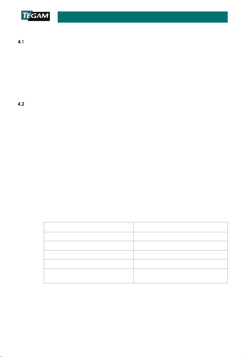
PARAMETER
VALUE
Thermocouple Type
As Desired
Temperature Units
°C
Offset Ch. 1
0.0 °C
Offset Ch. 2 (922B only)
0.0 °C
As Needed (see Section 3.11, Open
Wire Detection On/Off)
Figure 10: UUT Verification Parameter Settings
4. SERVICE INFORMATION
Inspection and Cleaning
To extend the life of the instrument, inspect and clean the instrument regularly. Inspect the
instrument for any significant abrasions, cuts, cracks, dents, or other signs of damage on
the case, keypad, and display lens. Inspect the connectors for breaks, dirt, or corrosion.
Ensure all screws are securely fastened, and if equipped, that the tilt stand/magnet/hanger
is in good condition and locks into position properly.
With all screws securely fastened and the battery compartment cover in place, use a damp
cloth or towel to wipe down the instrument. Use care to avoid scratching the display lens.
Mild, non-abrasive detergents may be used providing the instrument is then wiped down
with a clean damp cloth or towel.
Calibration
4.2.1 Verification Procedure
1. This procedure shall be performed within environmental conditions of 23 °C ±1 °C
and 5 % RH to 95 % RH.
2. The unit under test (“UUT”) shall be acclimated to the controlled environment for a
minimum of four (4) hours.
3. The equipment listed in Appendix A is required to fully verify the UUT to the
expanded instrument uncertainties specified in Appendix B.
4. Refer to Appendix C for standard measurement points and tolerances for each
thermocouple type.
5. One, several, or all the available thermocouple types may be verified as
necessary. In the steps below, use the appropriate Thermocouple Cable and
Thermocouple Calibrator settings as appropriate for the desired thermocouple
type.
6. For two channel UUTs, both channels may be verified concurrently.
7. Set the UUT parameters as shown in Figure 10 below. Refer to Section 3.3, Setup
Menu as necessary for UUT parameter setup instructions.
Open Wire Detection On/Off
8. Connect the miniature thermocouple connector of the Thermocouple Cable to
Channel 1 of the UUT.
a. For two channel UUTs using the Split Thermocouple Cable, connect the
miniature thermocouple connector of one leg to the UUT Channel 1
10 TEGAM WAY ● GENEVA, OHIO 44041 ● 440-466-6100 ● FAX 440-466-6110 ●
4-1
Page 27

Service Information
9. Connect the opposite end of the Thermocouple Cable (or the single-connector end
of the Split Thermocouple Cable) to the Thermocouple Calibrator thermocouple
output.
10. Set the Thermocouple Calibrator thermocouple type to the desired thermocouple
type.
11. Allow at least five minutes for this connection to stabilize.
12. Set the calibrator to output to the first Standard Value in Appendix C for the
desired thermocouple type.
13. Record the UUT measurement in the Reading column of Appendix C for the
appropriate Standard Value.
14. Record the cable correction value for the Thermocouple cable in the Cable
Correction column of Appendix C.
15. Subtract the Cable Correction value from the Reading and record the result as the
Corrected Reading (
Appendix C.
16. Compare the Corrected Reading to the tolerances stated in the 2-Sigma Tolerance
column of Appendix C to determine whether the UUT measurement is within
published specifications.
17. Repeat Steps 12 through 16 for each remaining Standard Value in Appendix C for
the current thermocouple type.
18. Repeat Steps 7 through 17 for each desired thermocouple type.
19. If Open Wire Detection was off in Step 7 above, enable the feature as shown in
Section 3.11, Open Wire Detection On/Off.
input, and the miniature thermocouple connector of the other leg to the
Channel 2 input.
Reading – Cable Correction = Corrected Reading) in
4.2.2 Alignment Procedure
Preparation
1. This procedure shall be performed within environmental conditions of 23 °C ±1 °C
and 5 % RH to 95 % RH.
2. The unit under test (“UUT”) shall be acclimated to the controlled environment for a
minimum of four (4) hours.
3. The equipment listed in Appendix A is required to align the UUT to the expanded
instrument uncertainties specified in Appendix B.
4. Remove the UUT battery door housing to expose the alignment access hole.
5. Press UUT to turn the UUT on.
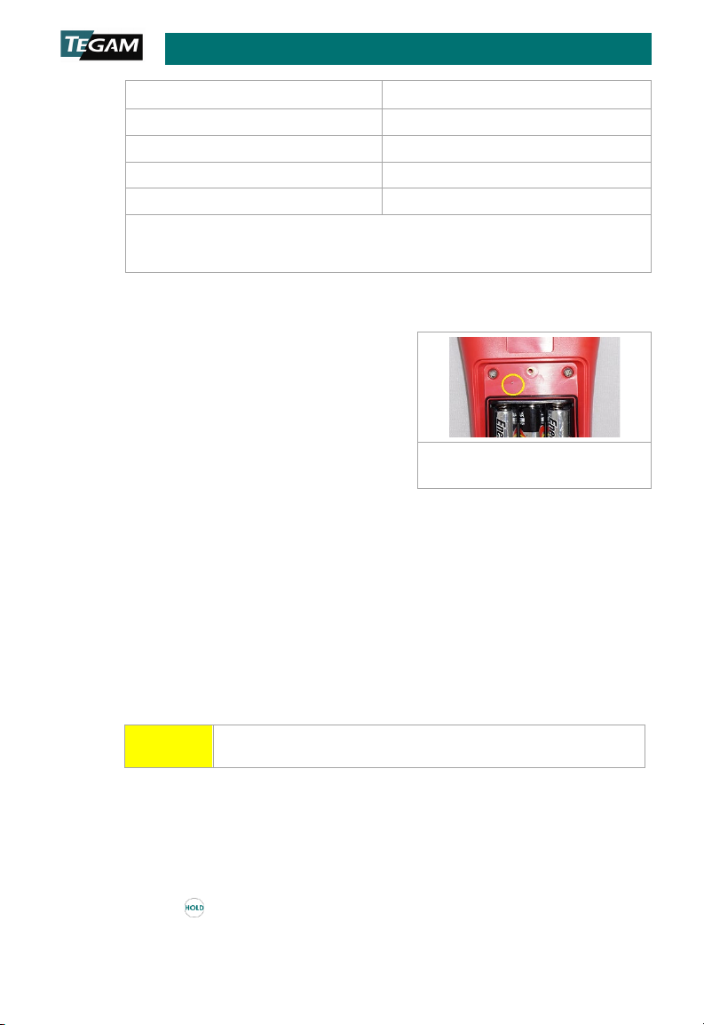
6. Set the UUT parameters as shown in Figure 11 be low. Refer to Section 3.3, Setup
Menu as necessary for UUT parameter setup instructions.
10 TEGAM WAY ● GENEVA, OHIO 44041 ● 440-466-6100 ● FAX 440-466-6110 ●
4-2
Page 28
Service Information
PARAMETER
VALUE
Thermocouple Type
Type E1
Temperature Units
°C
Offset Ch. 1
0.0 °C
Offset Ch. 2 (922B only)
0.0 °C
1
Other thermocouple types may be used in this procedure as desired. For instance, if the
in Appendix B assume alignment using Type E.
Figure 11: UUT Alignment Parameter Settings
Figure 12: Alignment Access
Hole Location
UUT is used primarily with Type J applications, Cold Junction Compensation may be
aligned using Type J. Note however that the expanded instrument uncertainties provided
7. Insert the Straightened Paper Clip through
the alignment access hole and gently press
the calibration enable switch located on the
circuit board. See Figure 12 for location.
Voltage Gain and Offset Alignment
8. The UUT display will indicate as follows:
a. Line 1: CAL1
b. Line 2: mV portion of Channel 1
voltage reading
c. Line 3: nV portion of Channel 1 voltage reading
9. Connect the miniature thermocouple connector of the Copper Mini-TC Cable to the
Channel 1 input of the UUT.
a. For two channel UUTs using the Split Copper Mini-TC Cable, connect one
miniature thermocouple connector to the Channel 1 input of the UUT,
and the other connector to the Channel 2 input.
10. Connect the opposite end of the Copper Mini-TC Cable (or Split Copper Mini-TC
Cable) to the appropriate output connectors of the DC Voltage Source.
11. Allow at least three minutes for the connections to temperature stabilize before
proceeding.
CAUTION
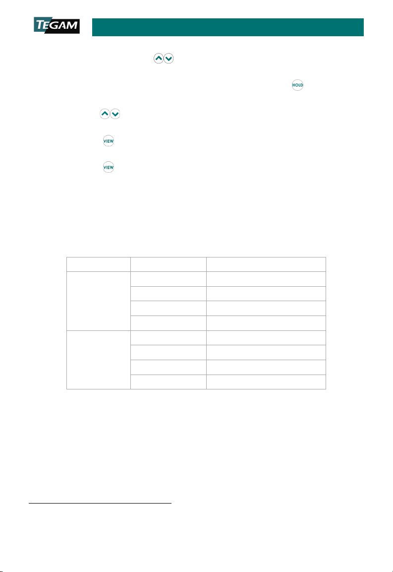
12. Set the DC Voltage Source to output the first Applied Voltage value in Figure 13
below.
13. Allow the DC Voltage source output to stabilize before proceeding.
14. The UUT will display the current voltage reading.
15. Allow the UUT displayed voltage to stabilize before proceeding.
16. Press UUT to automatically adjust the UUT voltage reading to the Applied
Voltage, ±0.001 mV.
10 TEGAM WAY ● GENEVA, OHIO 44041 ● 440-466-6100 ● FAX 440-466-6110 ●
Do not apply voltages greater than 80 mV DC to the UUT inputs. Voltages
greater than 80 mV may damage the instrument.
4-3
Page 29
Service Information
CHANNEL
UUT DISPLAY
APPLIED VOLTAGE (mV)
CAL1
-10
CAL2
(75
CAL3
-10
CAL4
(30 2 CAL5
-10
CAL6
(75
CAL7
-10
CAL8
(30
Figure 13: Gain Alignment Values
a. If the UUT displayed voltage is not within ±0.001 mV of the Applied
Voltage, press until the UUT displayed voltage is within
±0.001 mV, adjusting as close to the Applied Voltage as possible.
b. If the UUT displayed voltage is too far from nominal, may not
function as expected. The UUT will typically indicate 8999 or -999 in this
state. To set the active CAL factor to its default value, press the
(1.5s)
arrow buttons simultaneously for 1.5 seconds. Fine
adjustments may still be necessary.
17. Press UUT . The display will change to rES1 [2, 3 …] showing the actual
measured value saved in the previous step.
18. Press UUT again. This will increment to the next CAL value.
19. Repeat Steps 12 through 18 for each remaining value in Figure 13 below. For
single channel UUTs, omit Channel 2 values.
a. For two channel UUTs using the single-ended Copper Mini-TC Cable,
disconnect the cable from the UUT Channel 1 input, and reconnect the
cable to the Channel 2 input after completing CAL4 in Figure 13 below.
Repeat Step 11.
1
20. Remove the copper cable from the DC Voltage Source and UUT.
Cold Junction Compensation Alignment
21. Connect one end of the Type E
4
Thermocouple Cable to the UUT Channel 1 input.
a. For two channel UUTs using the Split Thermocouple Cable, connect the
miniature thermocouple connector of one leg to the UUT Channel 1
input, and the miniature thermocouple connector of the other leg to the
Channel 2 input.
4
If substituting another thermocouple type, use the appropriate Thermocouple Cable for the
selected thermocouple type.
4-4
10 TEGAM WAY ● GENEVA, OHIO 44041 ● 440-466-6100 ● FAX 440-466-6110 ●
Page 30

Service Information
22. Connect the opposite end of the Thermocouple Cable (or the single-connector end
of the Split Thermocouple Cable) to the Thermocouple Calibrator thermocouple
output.
The UUT display will indicate as follows:
a. Line 1: CALA
b. Line 2: temperature in °C
c. Line 3: temperature in tenths of °C (out to 0.000001 °C)
23. Set the Thermocouple Calibrator thermocouple type to Type E
24. Set the calibrator to output 0.0 °C.
25. Allow at least five minutes for this connection to stabilize.
26. Press UUT to set the UUT display equal to the Thermocouple Cable calibrated
correction value ± 0.02 °C.
27. Press UUT .
28. The display will change to rESA showing the actual measured value saved in the
previous steps.
29. For single channel UUTs, skip to Step 35 below.
30. For two channel UUTs, continue with Step 31.
a. For two channel UUTs using the single-ended Thermocouple Cable,
disconnect the cable from the UUT Channel 1 input, and reconnect the
cable to the Channel 2 input. Repeat Step 25.
31. Press UUT .
32. The UUT display will indicate as follows:
a. Line 1: CALb
b. Line 2: temperature in °C
c. Line 3: temperature in tenths of °C (out to 0.000001 °C)
33. Repeat Steps 26 and 27.
34. The display will change to rESb showing the actual measured value saved in the
previous steps.
5
.
35. Press UUT to save the current alignment values and return the UUT to normal
operation.
5
If substituting another thermocouple type, set the Thermocouple Calibrator as appropriate for
the selected thermocouple type.
10 TEGAM WAY ● GENEVA, OHIO 44041 ● 440-466-6100 ● FAX 440-466-6110 ●
4-5
Page 31
Service Information
Modes and Statistics)
Set probe offset to correct value for
Section 3.10, Probe Offset)
Observe display trend indicators and
Section 3.8 Trend Indicators)
Instrument is set to the
for the attached probe
Set the thermocouple type as
(see Section 3.3, Setup Menu)
When sourcing from a
enabled.
See Section 3.11, Open Wire
3.7, Hold Function)
Static discharge through
connected probes
Shuts down
will not power on
Replace batteries (see Section 2.7,
Replacement)
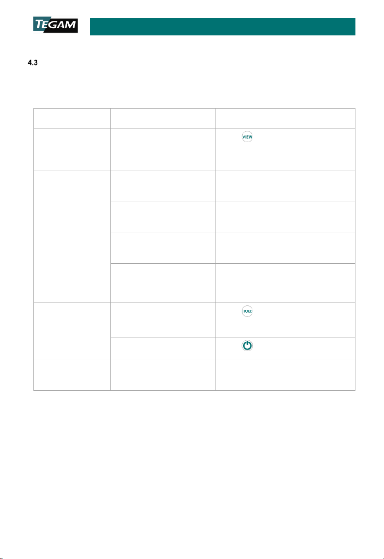
TEGAM’s digital handheld thermometers are designed and built to provide years of
uninterrupted use. In the event the instrument malfunctions or does not perform as
expected, helpful troubleshooting tips are provided below. Figure 14 below lists some of the
more common issues and their resolutions.
Troubleshooting
S
YMPTO M DESCRIPTION RESOLUTION
Unexpected
reading on Line 2
of Display
Unexpected or
Erroneous
Measurement
Unresponsive
unexpectedly or
Statistics View Mode is
active
Probe offset is active
Temperature probe has
not stabilized
wrong thermocouple type
thermocouple simulator,
Open Wire Detection is
Hold Mode is active
Batteries are low or
depleted
Press to cycle through statistics
views until active measurement is
displayed (see Section 3.4
connected temperature probe (see
wait for stable measurement (see
appropriate for the attached probe
Detection On/Off to disable.
Press , and verify that the HOLD
indicator is not active (see Section
Press to cycle instrument power
Battery Installation and
View
10 TEGAM WAY ● GENEVA, OHIO 44041 ● 440-466-6100 ● FAX 440-466-6110 ●
4-6
Page 32
Service Information
Figure 14: Common Troubleshooting Issues
Diagnostic Routines and Error Codes
The instrument momentarily activates all display annunciators and segments during startup
to allow for visual inspection of the LCD. Observe the LCD and verify all segments activate.
Internal diagnostic routines are also executed during startup. If any diagnostic routine
detects a malfunction, an error will be displayed as shown in Figure 15 below.
E
RROR CODE DESCRIPTION
Err ADC Analog to digital converter error
Err CJC Cold junction compensation error
Err FLSH Flash memory error
Err InP Stuck key or other keypad error
Figure 15: Diagnostic Routine Error Codes
Memory Sterilization
To erase all locally stored measurement data and reset accumulated statistics, press
See Section 3.12, Clear Function for instructions.
Instrument parameters will be retained. Refer to Section 3.3, Setup Menu to set instrument
parameters as desired.
(1.5s)
.
10 TEGAM WAY ● GENEVA, OHIO 44041 ● 440-466-6100 ● FAX 440-466-6110 ●
4-7
Page 33

Service Information
Preparation for Calibration or Repair Service
Once you have verified that the cause of the malfunction cannot be solved in the field and
the need for repair and calibration service arises, contact TEGAM customer service to obtain
an RMA (Returned Material Authorization) number. You can contact TEGAM customer service
via the TEGAM website, www.tegam.com
666-1010 (United States Only).
The RMA number is unique to your instrument and will help us identify you instrument and
to address the particular service request by you which is assigned to that RMA number.
Of even greater importance, a detailed written description of the problem should be attached
to the instrument. Many times repair turnaround is unnecessarily delayed due to a lack of
repair instructions or a detailed description of the problem.
This description should include information such as measurement range and other
instrument settings at the time of the malfunction, type of components being tested,
frequency of the symptoms (intermittent or continuous), conditions that may cause the
symptoms, changes to the test setup or operating environment that may affect the
instrument, etc. Any detailed information provided to our technicians will assist them in
identifying and correcting the problem in the quickest possible manner. Use a copy of the
Repair and Calibration Service form provided on the next page.
Once this information is prepared and sent with the instrument to our service department,
we will do our part to make sure that you receive the best possible customer service and
turnaround time possible.
or by calling 440-466-6100 (All Locations) or 800-
10 TEGAM WAY ● GENEVA, OHIO 44041 ● 440-466-6100 ● FAX 440-466-6110 ●
4-8
Page 34
Service Information
RMA#:
Instrument
Serial Number:
Company:
Technical
Phone
Additional
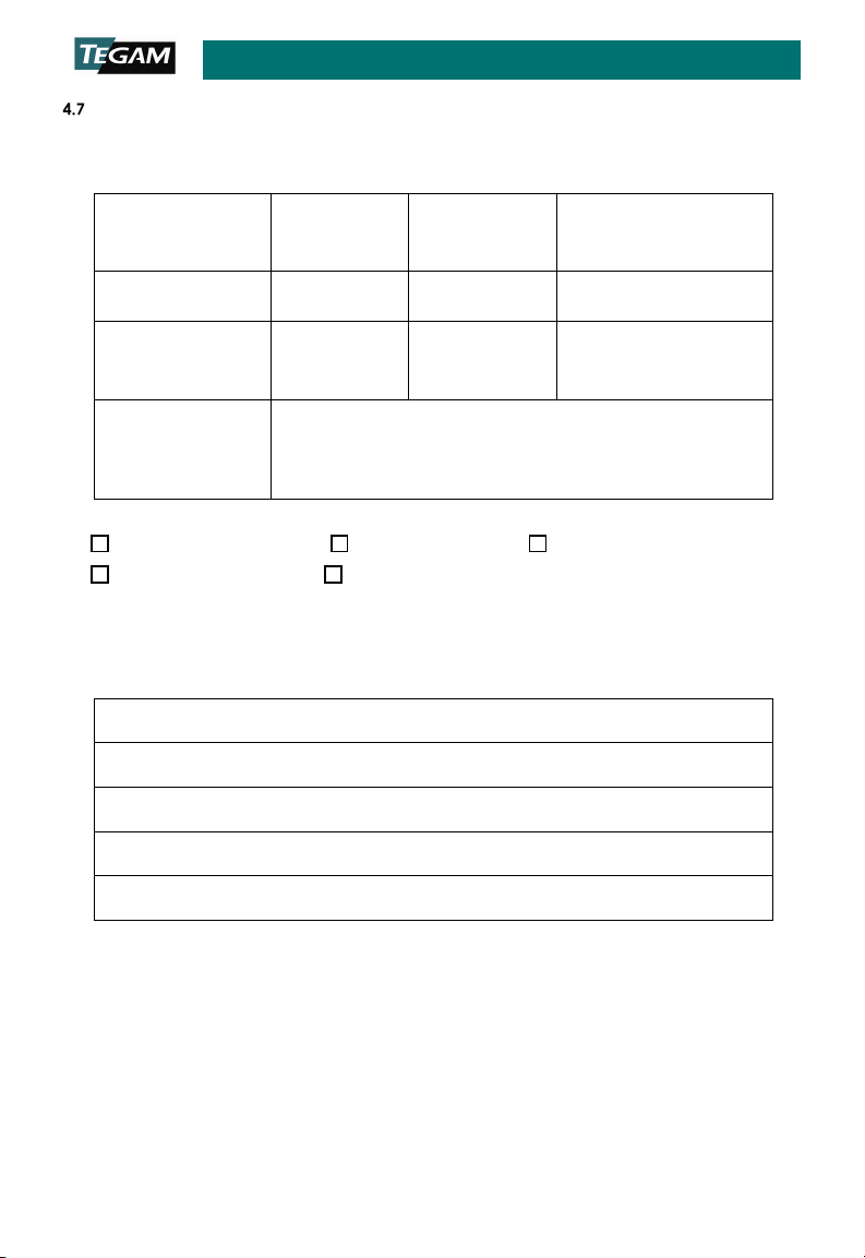
Expedite Repair & Calibration Form
Use this form to provide additional repair information and service instructions. The
completion of this form and including it with your instrument will expedite the processing
and repair process.
Model #:
Contact:
Number:
Contact Info:
Service Instructions:
Evaluation Calibration Only Repair Only
Repair & Calibration ISO 17025 Calibration with Data
Detailed Symptoms:
Include information such as measurement range, instrument settings, type of components
being tested, is the problem intermittent? When is the problem most frequent?, has
anything changed with the application since the last time the instrument was used?, etc.
10 TEGAM WAY ● GENEVA, OHIO 44041 ● 440-466-6100 ● FAX 440-466-6110 ●
4-9
Page 35

Service Information
Warranty
TEGAM, Inc. warrants this product to be free from defects in material and workmanship for a
period of three (3) years from the date of shipment. During this warranty period, if a
product proves to be defective, TEGAM Inc., at its option, will either repair the defective
product without charge for parts and labor, or exchange any product that proves to be
defective.
TEGAM, Inc. warrants the calibration of this product for a period of two (2) years from date
of shipment. During this period, TEGAM, Inc. will recalibrate any product, which does not
conform to the published accuracy specifications.
In order to exercise this warranty, TEGAM, Inc., must be notified of the defective product
before the expiration of the warranty period. The customer shall be responsible for
packaging and shipping the product to the designated TEGAM service center with shipping
charges prepaid. TEGAM Inc. shall pay for the return of the product to the customer if the
shipment is to a location within the country in which the TEGAM service center is located.
The customer shall be responsible for paying all shipping, duties, taxes, and additional costs
if the product is transported to any other locations. Repaired products are warranted for the
remaining balance of the original warranty, or 90 days, whichever is greater.
Warranty Limitations
The TEGAM, Inc. warranty does not apply to defects resulting from unauthorized
modification or misuse of the product or any part. This warranty does not apply to fuses,
batteries, or damage to the instrument caused by battery leakage.
The foregoing warranty of TEGAM is in lieu of all other warranties, expressed or implied.
TEGAM specifically disclaims any implied warranties of merchantability or fitness for a
particular purpose. In no event will TEGAM be liable for special or consequential damages.
Purchaser’s sole and exclusive remedy in the event any item fails to comply with the
foregoing express warranty of TEGAM shall be to return the item to TEGAM; shipping
charges prepaid and at the option of TEGAM obtain a replacement item or a refund of the
purchase price.
Statement of Calibration
This instrument has been inspected and tested in accordance with specifications published
by TEGAM, Inc.
TEGAM, Inc. certifies the above listed instrument has been inspected and calibrated and
meets or exceeds all published specifications and has been calibrated using standards whose
accuracies are traceable to the International System of Units (SI) through the National
Institute of Standards and Technology (NIST) or other recognized National Metrology
Institutes.
10 TEGAM WAY ● GENEVA, OHIO 44041 ● 440-466-6100 ● FAX 440-466-6110 ●
4-10
Page 36

Appendices
S
DC Voltage Sourc e
DC Voltage Output
-10 to 75 mV
± (30 ppm of output + 2 µV)
600 to 799 °C
1550 to 1820 °C
± 0.36 °C
± 0.23 °C
-250 to -201 °C
600 to 1000 °C
± 0.26 °C
± 0.12 °C
-210 to -101 °C
800 to 1200 °C
± 0.15 °C
± 0.12 °C
-200 to -101 °C
800 to 1372 °C
± 0.17 °C
± 0.14 °C
-250 to -201 °C
800 to 1300 °C
± 0.73 °C
± 0.13 °C
-50 t o -26 °C
1600 °C
± 0.55 °C
± 0.24 °C
-50 t o -26 °C
1600 °C
± 0.51 °C
± 0.27 °C
-250 to -201 °C
0 to 400 °C
± 0.36 °C
± 0.11 °C
A. REQUIRED EQUIPMENT
EQUIPMENT FUNCTION RANGE
Thermocouple
Calibrator
1, 2
Thermocouple
Type B
Thermocouple
Type E
Thermocouple
Type J
Thermocouple
Type K
Thermocouple
Type N
Thermocouple
Type R
Thermocouple
Type S
800 to 1549 °C
-200 to -101 °C
-100 to -1 °C
0 to 599 °C
-100 to 799 °C
-100 to 799 °C
-200 to -101 °C
-100 to -1 °C
0 to 799 °C
-25 t o -1 °C
0 to 99 °C
100 to 399 °C
400 to 599 °C
600 to 999 °C
1000 to 1599 °C
-25 t o -1 °C
0 to 99 °C
100 to 399 °C
400 to 599 °C
600 to 1599 °C
PECIFICATION
(2-SIGMA)
± 0.29 °C
± 0.13 °C
± 0.11 °C
± 0.10 °C
± 0.11 °C
± 0.12 °C
± 0.24 °C
± 0.13 °C
± 0.12 °C
± 0.45 °C
± 0.39 °C
± 0.29 °C
± 0.23 °C
± 0.22 °C
± 0.20 °C
± 0.43 °C
± 0.38 °C
± 0.30 °C
± 0.24 °C
± 0.23 °C
10 TEGAM WAY ● GENEVA, OHIO 44041 ● 440-466-6100 ● FAX 440-466-6110 ●
Thermocouple
Type T
-200 to -101 °C
-100 to -1 °C
A-i
± 0.17 °C
± 0.12 °C
Page 37

Appendices
S
Thermocouple Cables must be calibrated to a 2-Sigma uncertainty of 1 µV or less.
Copper Mini-TC Cable is required for Voltage Gain and Offset alignment only. This
Straightened Paper
Clip
Required to access the calibration enable switch. Any rigid wire, approximately
0.8 mm in diameter, may be used.
EQUIPMENT FUNCTION RANGE
Calibrated Thermocouple Cables with recorded correction values shall be used
throughout this procedure to adhere to the expanded instrument uncertainties
provided in Appendix B.
Thermocouple
Cables
Copper Mini-TC
Cable
1
Fluke 7526A meets the Thermocouple Calibrator specifications of Appendix A.
2
All “Specification (2-Sigma)” col umn values rounded up to nearest hundredth.
Thermocouple Cables are only required for each desired thermocouple type.
The thermocouple cables must be terminated at one end with a male miniature
thermocouple connector for connection to the UUT. The opposite end should be
terminated as appropriate for the thermocouple calibrator.
For two channel UUTs, a split or “Y” cable may be used, terminated with two (2)
male miniature thermocouple connectors. Correction values must be established
for each leg of the Split Thermocouple Cable.
cable does not require calibration.
One end shall be terminated with a male miniature thermocouple connector for
connection to the UUT. The opposite end shall be terminated with copper
connections appropriate for the DC Voltage Source.
For two channel UUTs, a split or “Y” cable may be used, terminated with two (2)
male miniature thermocouple copper connectors.
Appendix A: Required Equipment
PECIFICATION
(2-SIGMA)
A-ii
10 TEGAM WAY ● GENEVA, OHIO 44041 ● 440-466-6100 ● FAX 440-466-6110 ●
Page 38
Appendices
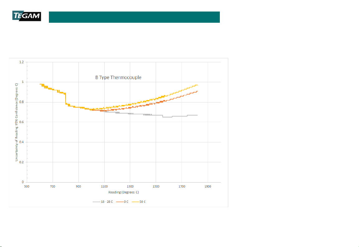
B. EXPANDED INSTRUMENT UNCERTAINTIES
Thermocouple Type B
B-i
Page 39
Appendices
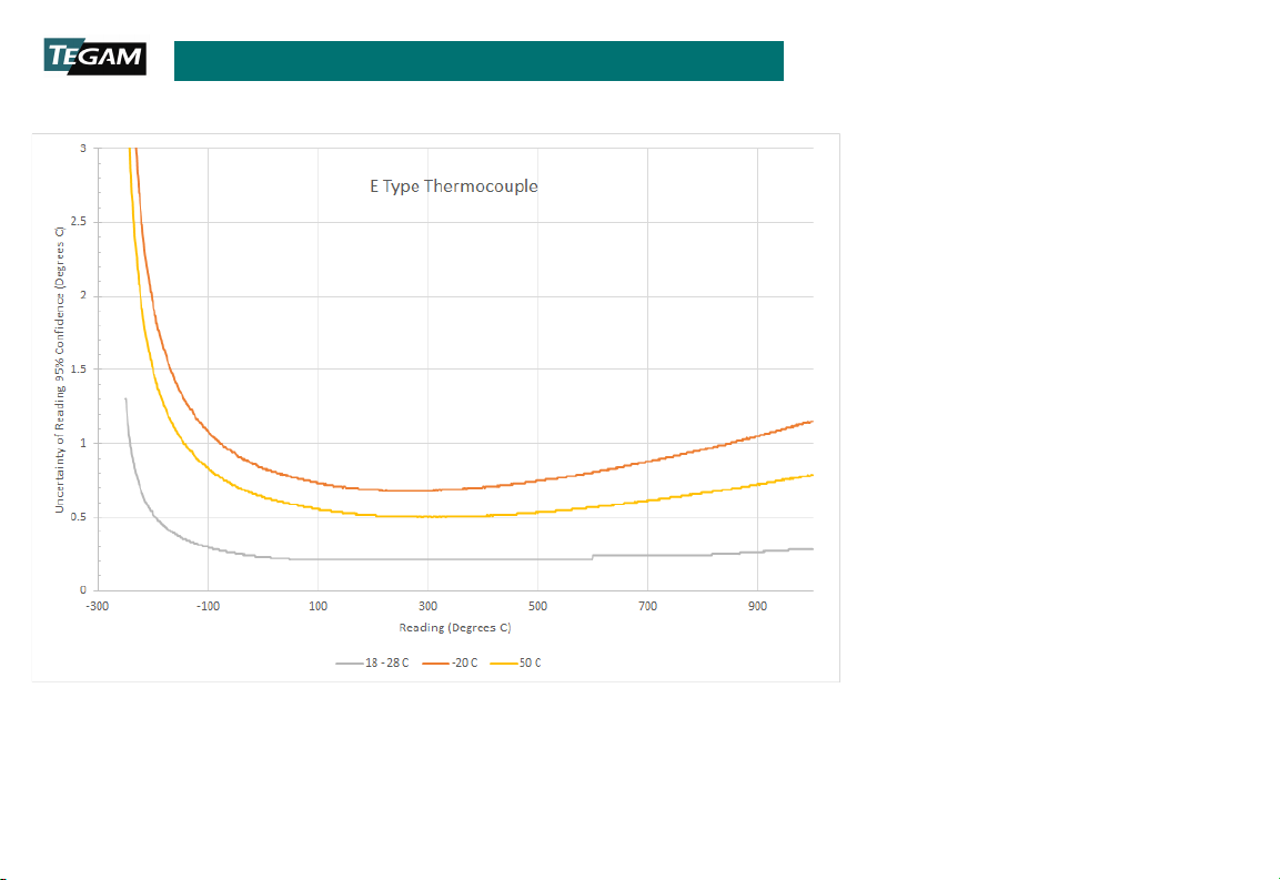
Thermocouple Type E
B-ii
Page 40
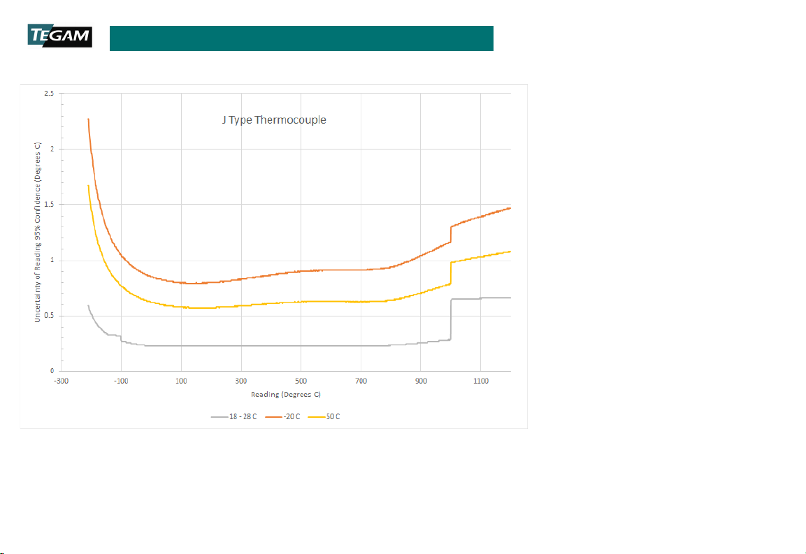
Appendices
Thermocouple Type J
B-iii
Page 41
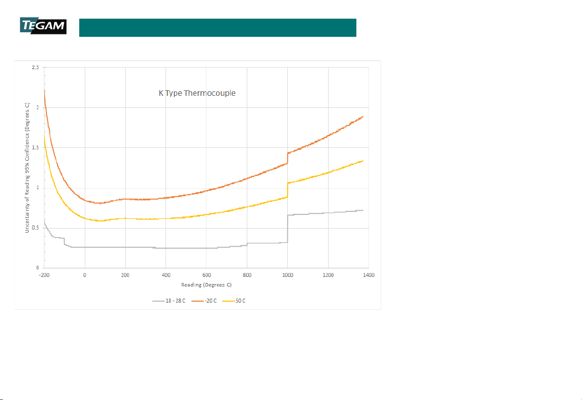
Appendices
Thermocouple Type K
B-iv
10 TEGAM WAY ● GENEVA, OHIO 44041 ● 440-466-6100 ● FAX 440-466-6110 ● [email protected]
Page 42
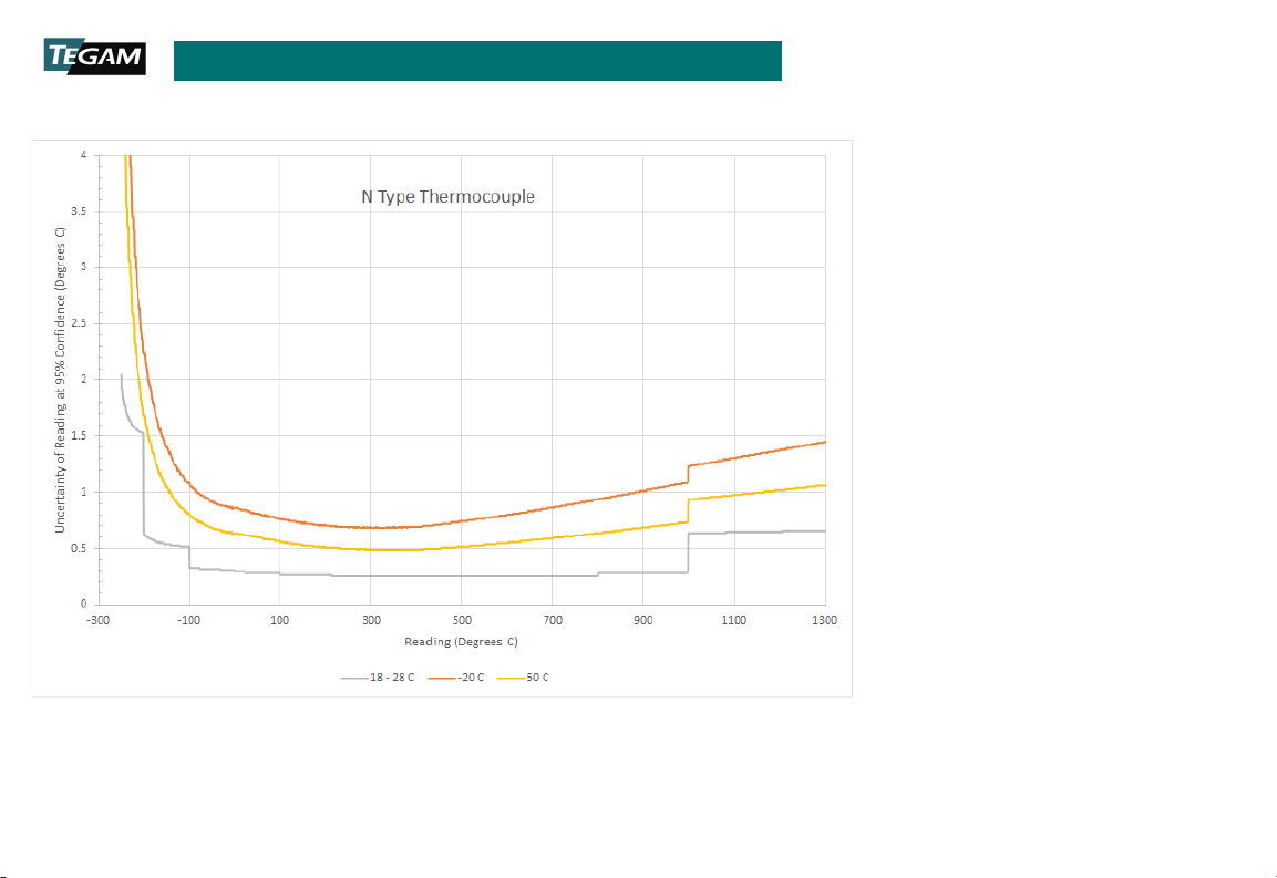
Appendices
Thermocouple Type N
B-v
10 TEGAM WAY ● GENEVA, OHIO 44041 ● 440-466-6100 ● FAX 440-466-6110 ● [email protected]
Page 43
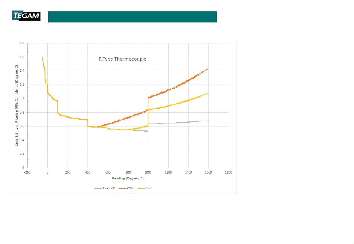
Appendices
Thermocouple Type R
B-vi
10 TEGAM WAY ● GENEVA, OHIO 44041 ● 440-466-6100 ● FAX 440-466-6110 ● [email protected]
Page 44
Appendices
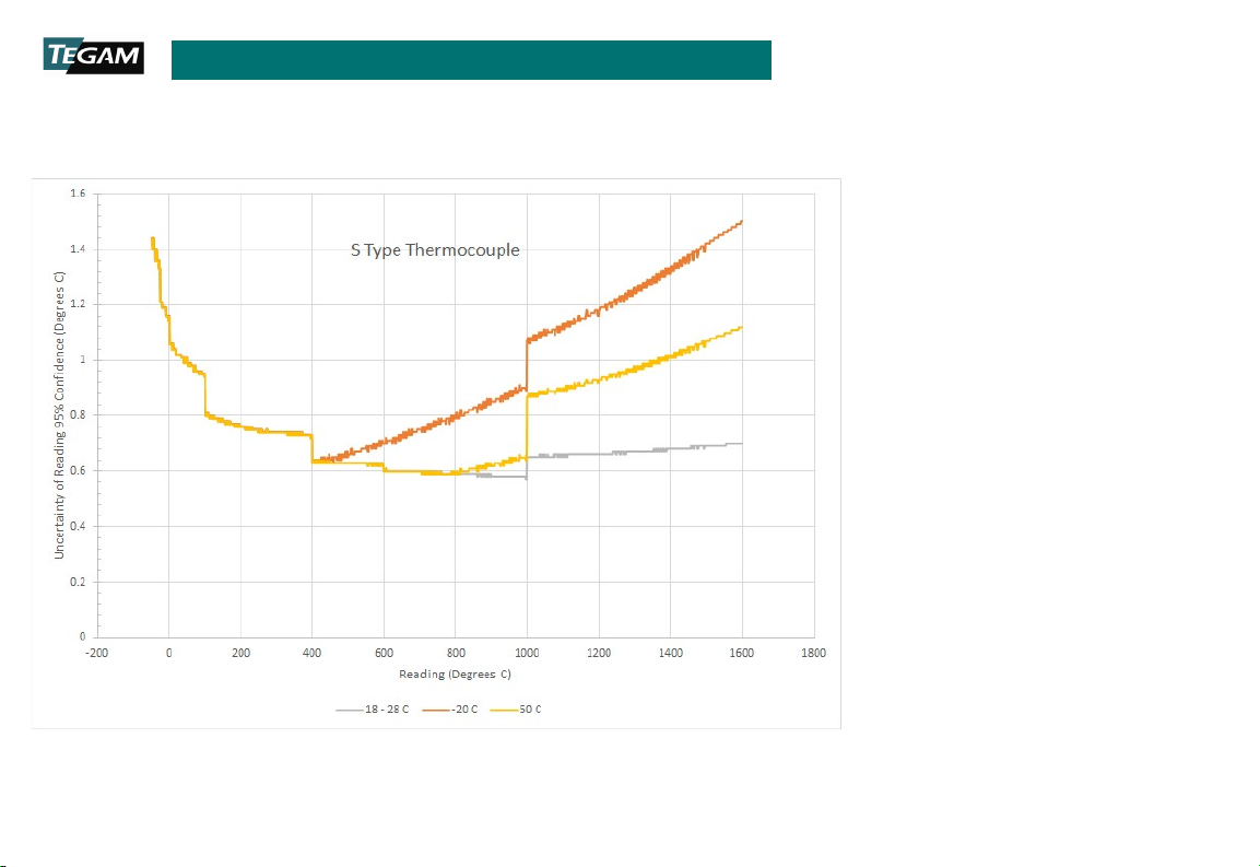
Thermocouple Type S
B-vii
10 TEGAM WAY ● GENEVA, OHIO 44041 ● 440-466-6100 ● FAX 440-466-6110 ● [email protected]
Page 45
Appendices
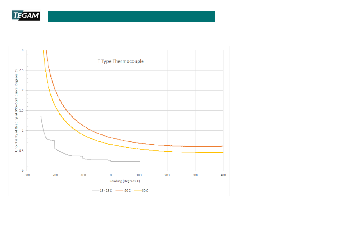
Thermocouple Type T
B-viii
10 TEGAM WAY ● GENEVA, OHIO 44041 ● 440-466-6100 ● FAX 440-466-6110 ● [email protected]
Page 46

Appendices
T
-
TYPE
R
C
(°C)
C
R
2-S
T
(± °C)
600
0.98
995
0.73
1820
0.67 E -250
1.30
-95
0.29
0
0.23
995
0.28 K -200
0.59
-95
0.29
0
0.26
995
0.32
1372
0.72 J -210
0.59
-95
0.27
0
0.23
995
0.28
1200
0.66 N -200
0.63
-95
0.33
0
0.30
995
0.29
1300
0.66 R 0
1.08
995
0.53
1600
0.69 S 0
1.06
995
0.58
1600
0.70 T -250
1.36
-95
0.31
0
0.24
400
0.23
C. INSTRUMENT VERIFICATION DATA SHEET
HERMO
COUPLE
B
STANDARD
VALUE (°C)
EADING (°C)
ABLE OFFSE T
ORRECTED
EADING (°C)
IGMA
OLERANCE
Appendix C: Instrument Verification Worksheet
C-i
10 TEGAM WAY ● GENEVA, OHIO 44041 ● 440-466-6100 ● FAX 440-466-6110 ●
Page 47

TEGAM I NC.
10 TEGAM WAY
GENEVA, OHIO 44041
CAGE Code: 49374
WEB: http://www.tegam.com
10 TEGAM WAY ● GENEVA, OHIO 44041 ● 440-466-6100 ● FAX 440-466-6110 ●
 Loading...