

Page 1
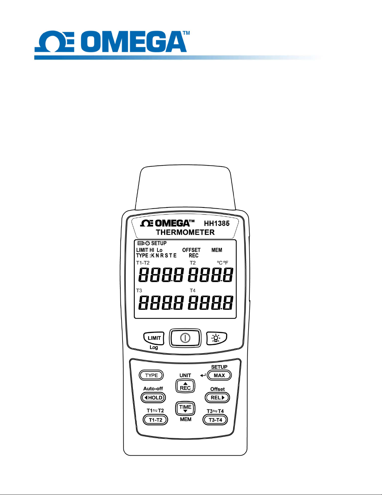
HH1385
User Manual
HH1385
4-Channel Thermometer
User’s Manual
1
Page 2
1. Introduction
The HH1385 is a digital 4 input thermometer and data logger that works with any K, J, E, T,
R, S, N type thermocouple temperature sensors. This unit offers higher accuracy and better
uniformity across various thermocouple types. This device measures/stores over 16,800
temperature readings and allows up to 4 thermocouple connections that plug into a miniature
female thermocouple receptacle at the base of the unit.
The user can easily set up the initial data logging parameters including thermocouple type,
logging Intervals, high/low alarm settings, and desired temperature units (°C,°F or °K). The
user may also download the stored data by plugging the meter straight into a PC’s USB port
and running the easy-to-use Windows software.
2. Accessories
1 User manual
6 1.5V AAA Carbon zinc battery
1 Carrying bag
1 9V AC to DC adaptor
1 USB cable
3. Safety Precaution
Note! Please refer to this manual.
Improper use may damage the
meter and its components.
Complies with European Directive.
Do not operate in environments with flammable gas or humid environments
Operating altitude: up to 2000M
Operating environment: Indoor use; Pollution degree 2
Clean with soft cloth when dirty, such as glasses cloth
Do not clean with chemicals and other solvents
Class B – Equipment for use in all establishments other than domestic
Group 1 – RF energy generated is needed for the internal functioning
2
Page 3
Without heat
-
sensing wire connected,
will appear on the screen.
4. Meter Description
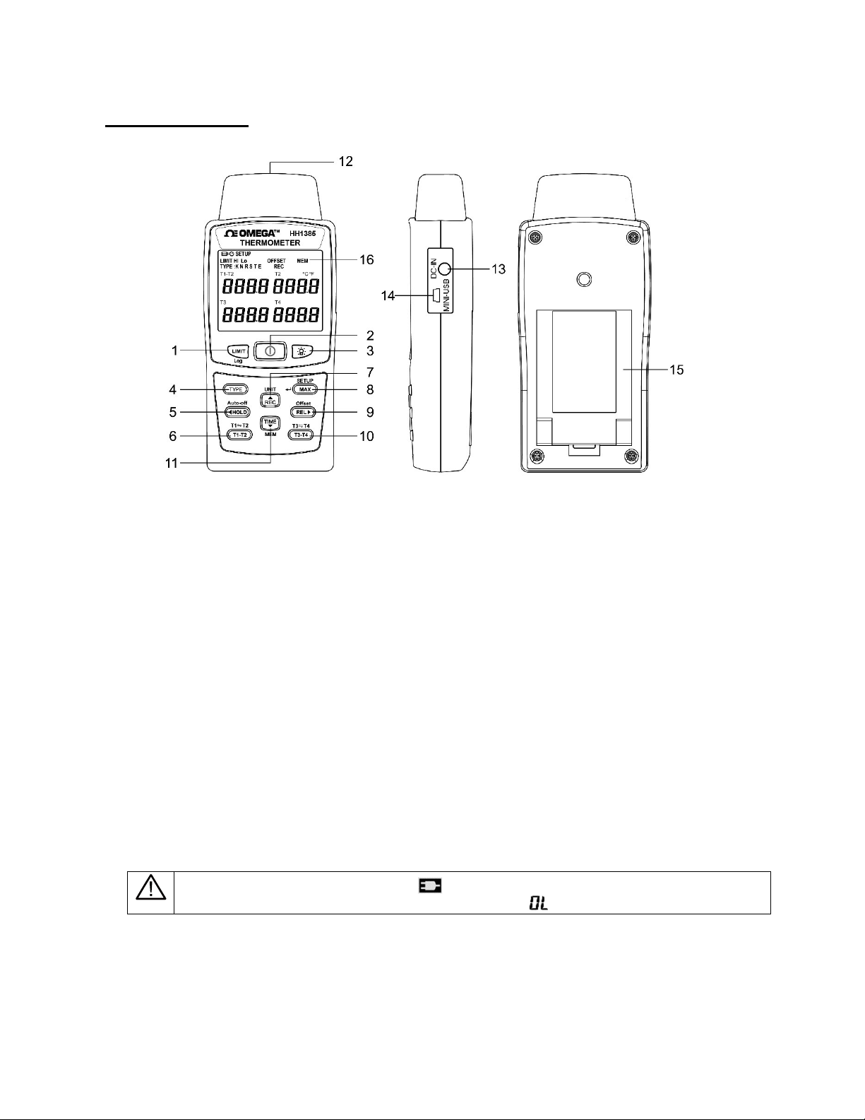
1. Alarm setup button / Auto record button
2. Power button
3. Backlight button
4. K /J/ T / E/ R / S/ N type switching/manually record button.
5. Hold button / Auto-shutdown button
6. Interchange button for "T1 - T2" vs. "T1 & T2"
7. Unit ° C / ° F / K switch button
8. Maximum value, Minimum value, Average value, elapsed time / Setup button
9. Relative value / offset value button
10. Interchange button for "T3 - T4" vs. "T3 & T4"
11. Time button / Read button
12. Thermocouple input terminal T1/T2 T3/T4
13. External power DC 9V input
14. USB data output jack
15. Battery cover and tilt stand
16. LCD display
With DC-IN connected, appears on the screen.
3
Page 4
5. Operation
Power on or off
Press button,turn on or turn off.
Turn on backlight
Press button to turn on or turn off the backlight.
*The backlight will automatically turn off after being lit for 15 seconds.
Alarm on or off
Press to turn “on” or “off” the alarm, followed by "LIMIT" appears on the LCD.
This LCD shows the status "on" or "off" of the alarm function. It is possible to set the upper
and lower limit of the temperature range by yourself. When the temperature reading
exceeds the range, the buzzer will alarm until the temperature back to the range or the
alarm function turned off.
(For the limit range setup, please enter Setup Function)
Auto Recording
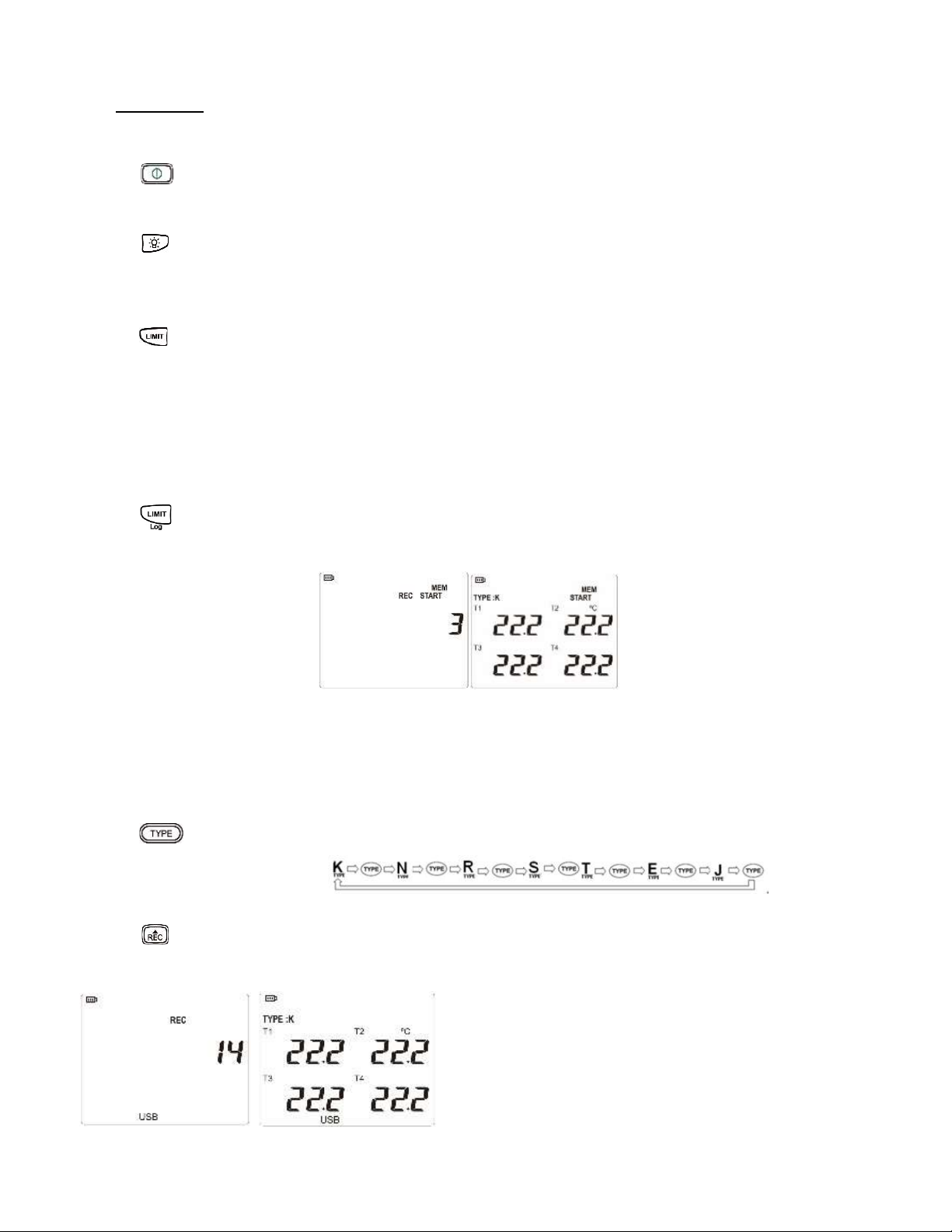
Press and hold for ≥ 2 seconds to enable or disable the auto-recording function "LOG"
The LCD display will first show the number of logs for REC/MEM START mode and then
switch back to temperature mode after 1 second.
The auto-recording is such if the current number is 3, it will be increased to X by 1 at each
pressing. (the number of logs in HH1385 is up to 16800)
* Execute "LOG" to disable the auto-shutdown function. For recording for a long time,
please connect the meter to an external power supply.
Thermocouple Type Selection (TYPE):
Press to enable selection of different thermocouple types in a full cycle.
Manual Record
Press , followed by "REC" appears on the LCD, the log number of records will increase
by +1 at each time, and one log will be recorded.
The manual records are up to 200 logs.
4
Page 5
Unit Switch for °C, °F and °K
Press and hold for ≥ 2 seconds to switch the unit: Celsius (°C), Fahrenheit (°F), or Kelvin
(°K).
Data Hold
Press to enable or disable the data hold function.
Disable Auto Power Off Function
Press and hold for 2 seconds to enable or disable the auto power off function.
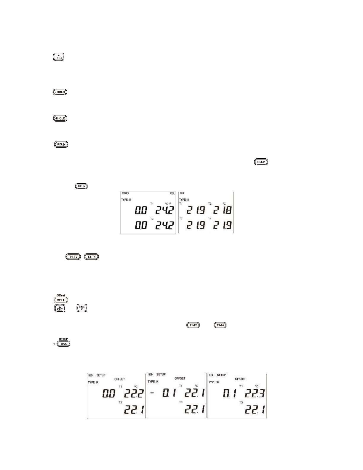
Relative Value Measurement
Press to enter the relative:
Just use one thermocouple, the difference between the two temperatures can be measured.
For example, measure the first temperature as 25°C, and then press to show 0°C on
the LCD. Again, measure the second temperature. If the second temperature is measured
as 30°C, the LCD will show the difference value 5°C (30-25=5°C).
Again, press to disable the function.
The left shows the relative value, right shows the temperature value being measured.
Press the / and hold to switch the display between "T1 & T2" and "T3 & T4".
Offset Value
The user can set the offset value to compensate for the error due to the working
thermocouple wire.
Press and hold for ≥ 2 seconds to set the offset value in OFFSET mode.
Press or to increase or decrease the offset value by the scale of 0.1°C, °F, or °K.
The setting range is ±5°C, ±5K, or ±9°F.
*If to set offset value of another channels, press and to switch and select between
"T1 & T2" and "T3 & T4" for adjustment.
Press to save the setting value and exit the setting mode.
*If the value updated to be 0.1, "OFFSET" will continuously appear on the LCD. "OFFSET"
will not disappear unless it is corrected back to 0.0.
5
Page 6
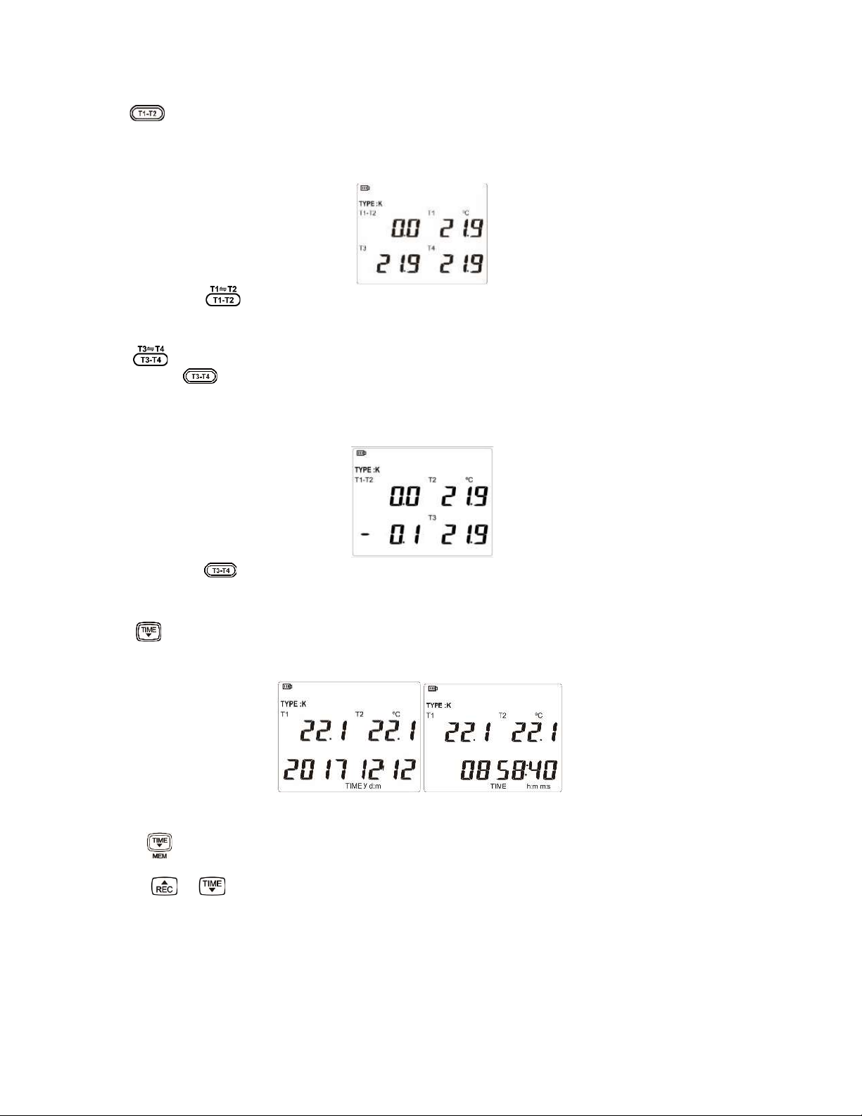
Change Display of T1-T2 vs. T1 & T2
Press to enable or disable T1 – T2 .
The value shown on the left shows the difference of T1 – T2, and the one shown on the
right is the T1 value which is measured presently.
Press and hold for ≥ 2 seconds for the position change of T1 and T2.
Change Display of T3-T4 vs. T3 & T4
Press to show the value of T3 - T4.
Again, press to disable the function.
The value shown on the left presents the difference of T3-T4, the one shown on the right is
the temperature measured through T3 channel.
Press and hold for 2 seconds for the position change of T4 and T3 on the right.
Time Display
Press for < 1 second to switch the three date-time modes: Year/Month/Day →
Hour/Minute/Second → Cyclic displays each term by second.
Read Record
Press and hold for ≥ 2 seconds to read the records in "MEM" mode while LCD displays
MEM CALL.
Press or to read the previous or next record.
The three items of time, number of logs and temperature data are displayed on the LCD
and are auto-displayed cyclic by second.
6
Page 7
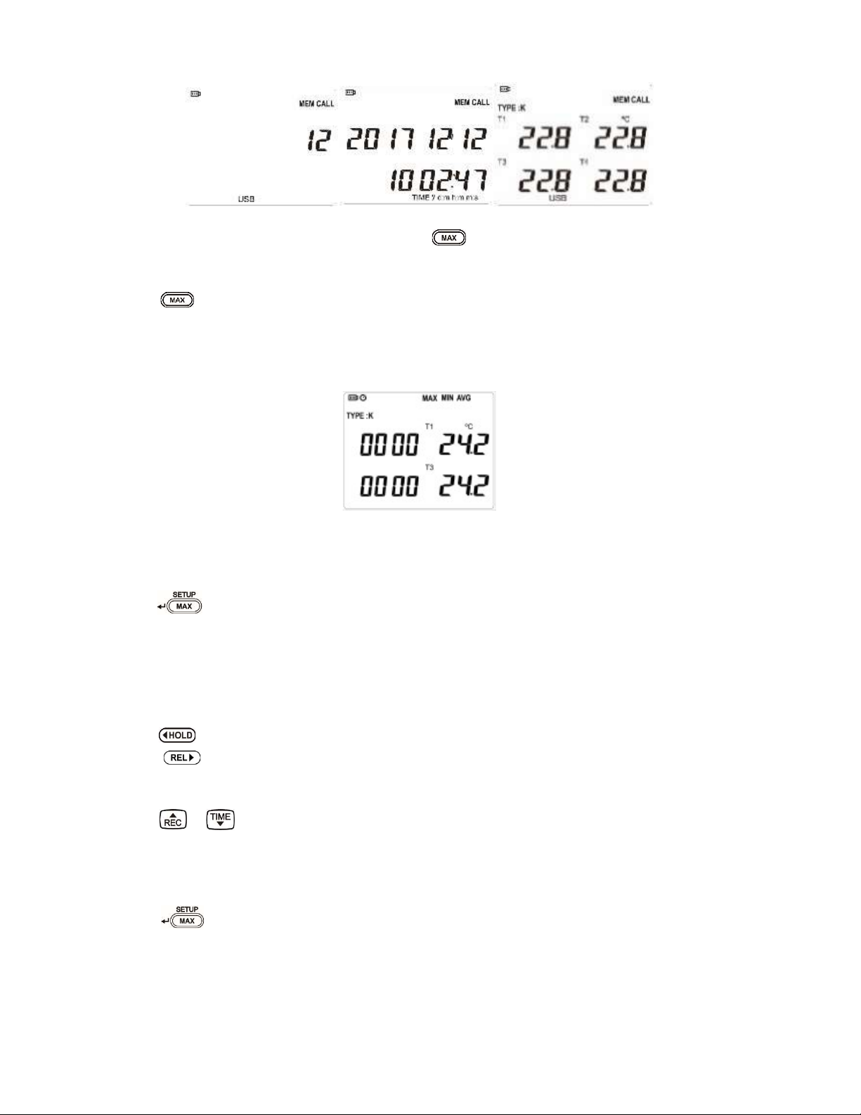
It is used in the "MEM CALL" mode. Press to exit this mode.
Maximum /Minimum/ Average Value
Press repeatedly to select maximum, minimum and average value of measured
data.
When MAX, MIN, and AVG are displayed at the same time, it represents the elapsed
time of the measurement, and the present temperature T1 / T3.
Setup
Press and hold for ≥ 2 seconds for SETUP
Step1. High/Low limit Value setting for alarm function (Limit)
Select Setup mode to the upper and lower limit of T1, T2, T3 and T4 (Setup Limit Hi、
Lo).
Press to select and set the range (Hi & Lo) of T1, T2, T3, T4.
Press to select the position to be modified. The position will be indicated to the
next one by each press.
Press or to set the plus-minus sign and temperature.
The setting of the upper and the lower limits are based on the TYPE range measured;
it may auto-identify whether it exceeds the limit. (The Setup function will fail if it exceeds
the TYPE range which is set by the user.)
Press to save the settings and proceed to Step 2.
7
Page 8
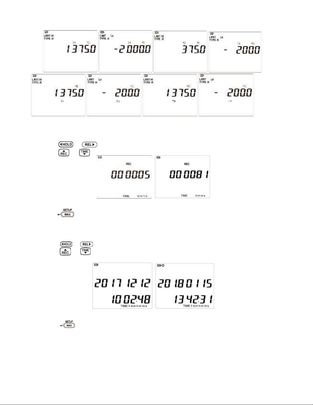
Step2. Set Record Intervals
Press or to select the hour, minute, and second.
Press or to adjust the record interval.
Press to save the settings and proceed to Step 3.
Step3. Time Setting
Press or to select the year, month, day, hour, minute, and second.
Press or adjust the time.
Press and hold the button to enable speedy adjustment.
Press to save the settings and proceed to Step 4.
8
Page 9
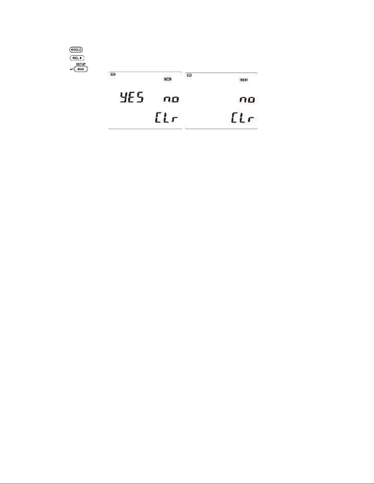
Step4. Clear the record in the memory
Press to clear, "YES" will flash.
Press to keep, "NO" will flash.
Press to save the settings and complete all settings.
9
Page 10
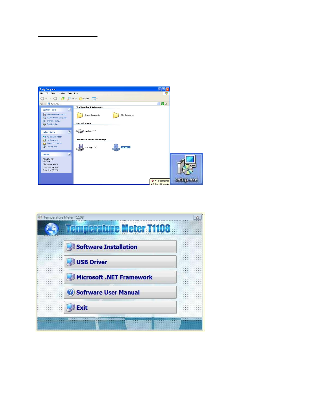
6. Software Installation
Supported operating systems: XP/Windows7/Windows 8.1/Windows10
Install the desktop thermometer program (Please close virus scanning software when
Executing.)
Place the CD into the CD/DVD-ROM player
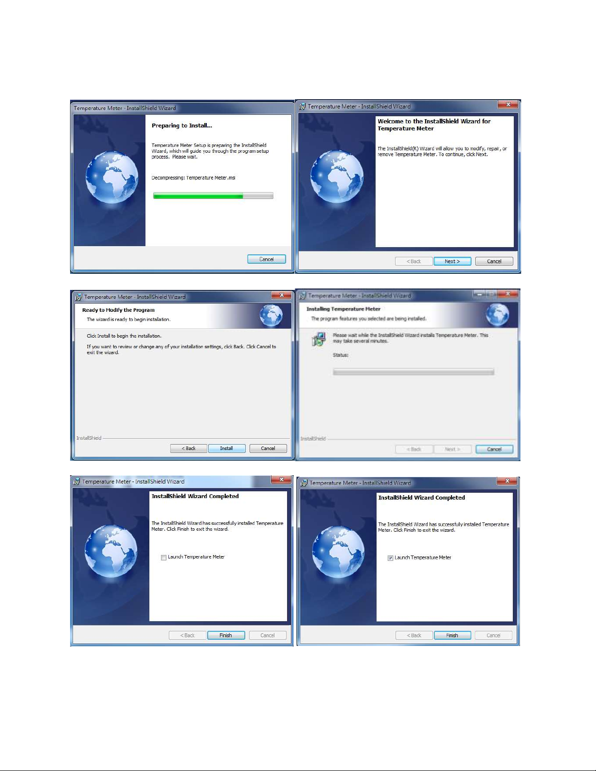
Install the Temperature Meter T1 software
This will install Temperature Meter T1 Version 1.0.08 on your computer. It is recommended that you close all
other applications before continuing. Click next to continue, or Cancel to exit Setup
10
Page 11
11
Page 12
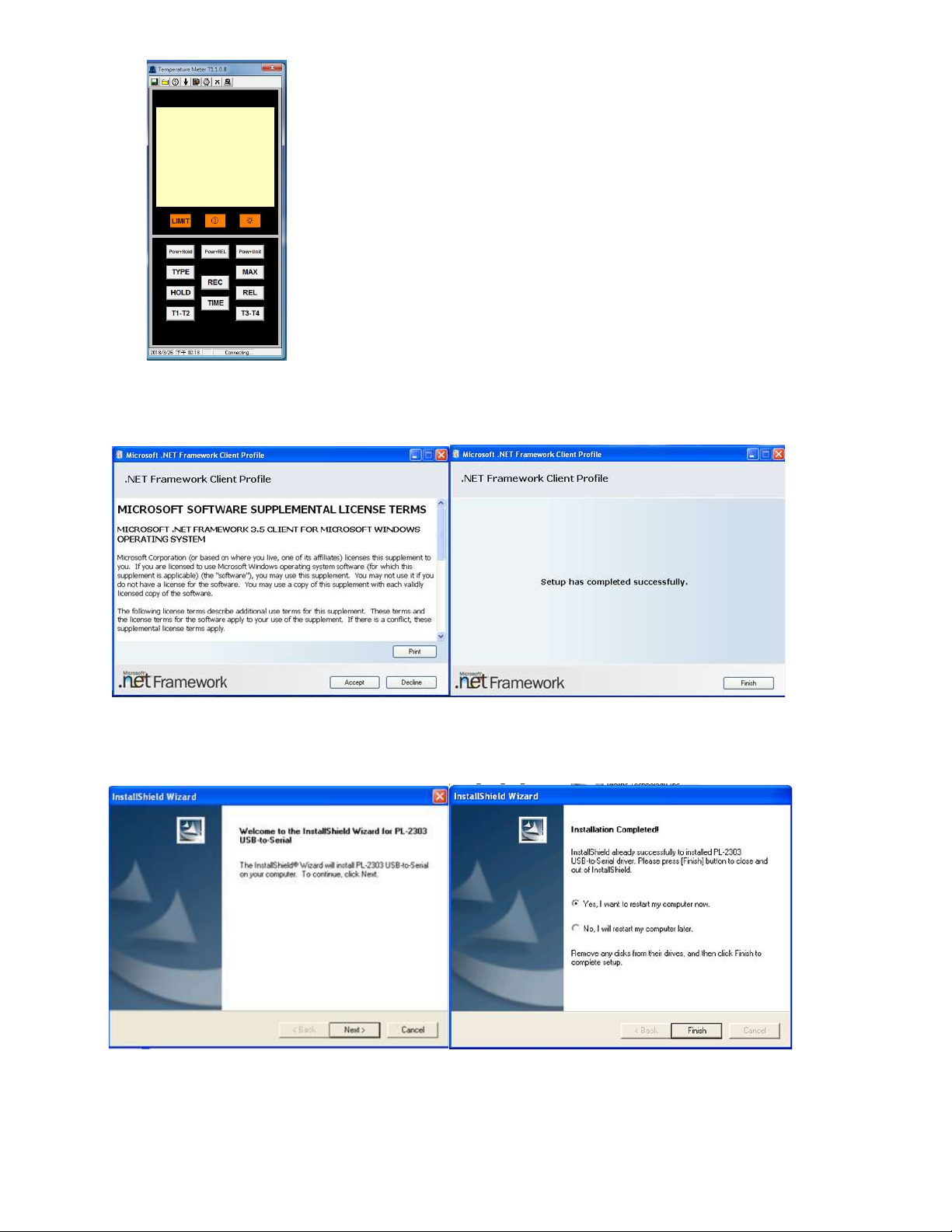
Finish Install and run Temperature Metert11.0.08 desktop
software.
(HH1385 is not connected to the PC)
Install Microsoft NET Framework Client Profile
Install Shield Wizard of PL2303
The Install Shield Wizard will install PL-2303 USB-to-Serial on your computer.
12
Page 13
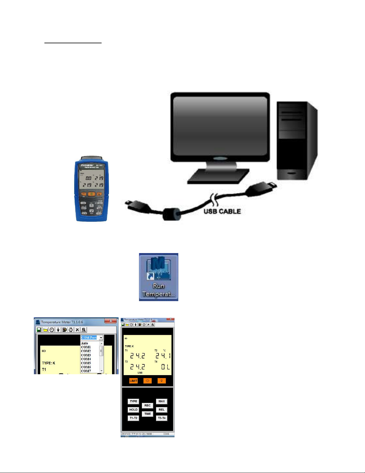
7. Software manual
Connect the USB cable included with a meter to the PC, as shown in the figure
below.
Double click “Run Temperature Meter T1110” icon on the desktop
Select COM port connect to the PC
“USB”: PC is connected to a meter
13
Page 14
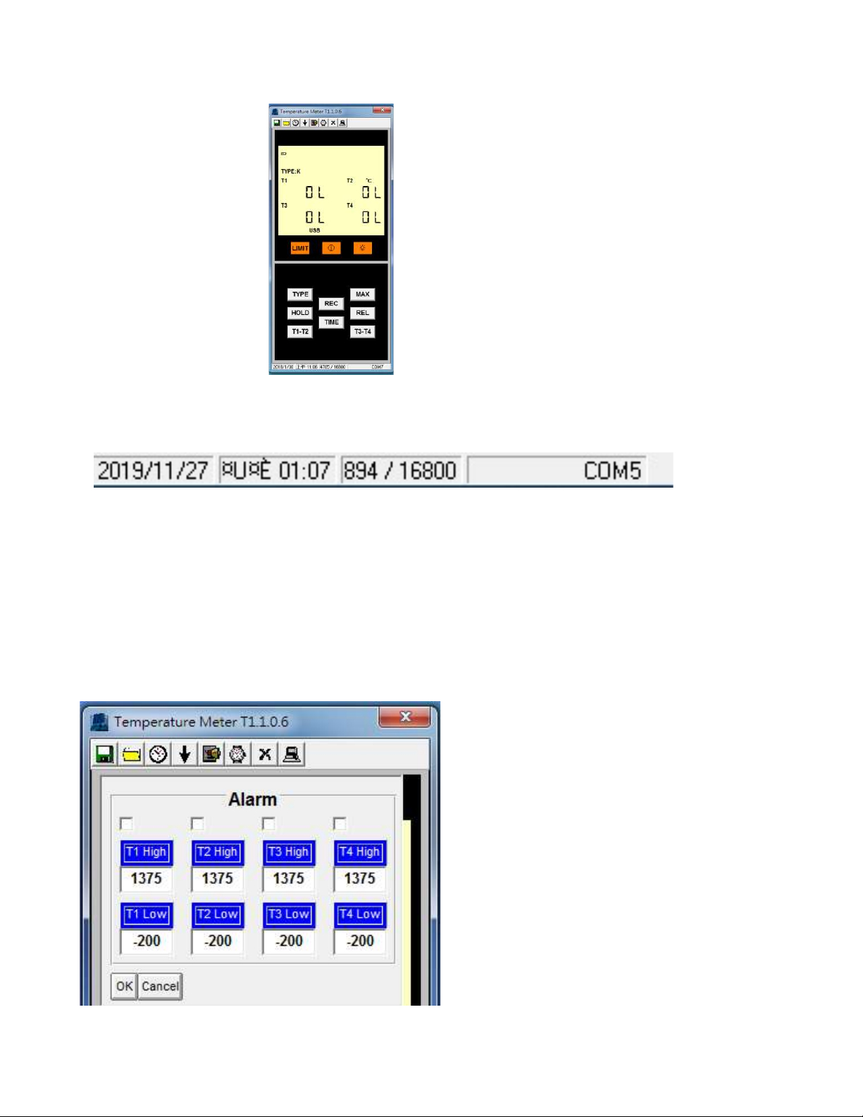
“OL”: No Thermocouple connected
Year / Month / day 2019/11/27 Hour: Minute 01:07
Number of records / Total number of records 894/16800
Connection port COM5 (random change)
Select the “Start to record measured data Alarm function T1 / T2/T3/T4 Upper / lower
limit setting (Alarm)
14
Page 15
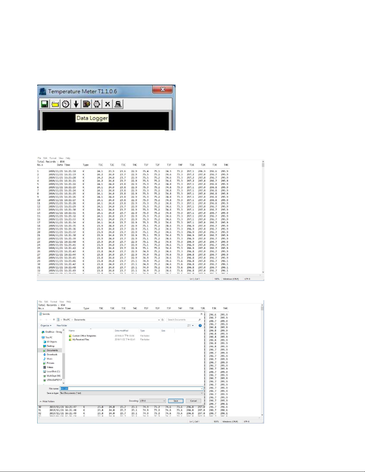
Download Temperature Meter data from the meter’s memory
Select the “Download recorded measurement record from / Temperature Meter”
Save the record after the completion of the download
Save a new file (*.txt)
15
Page 16
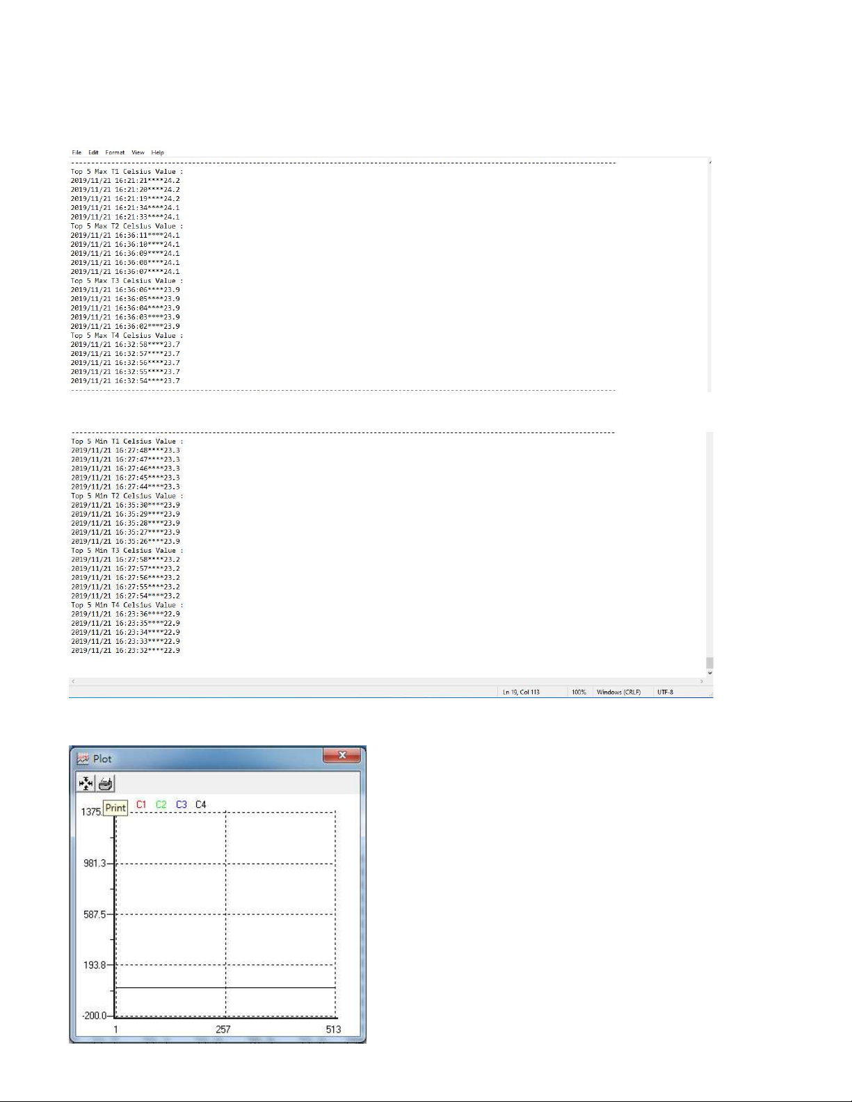
Top 5 highest data of T1 T2 T3 T4
Top 5 lowest data of T1 T2 T3 T4
Print T1 T2 T3 T4 temperature Chart
16
Page 17
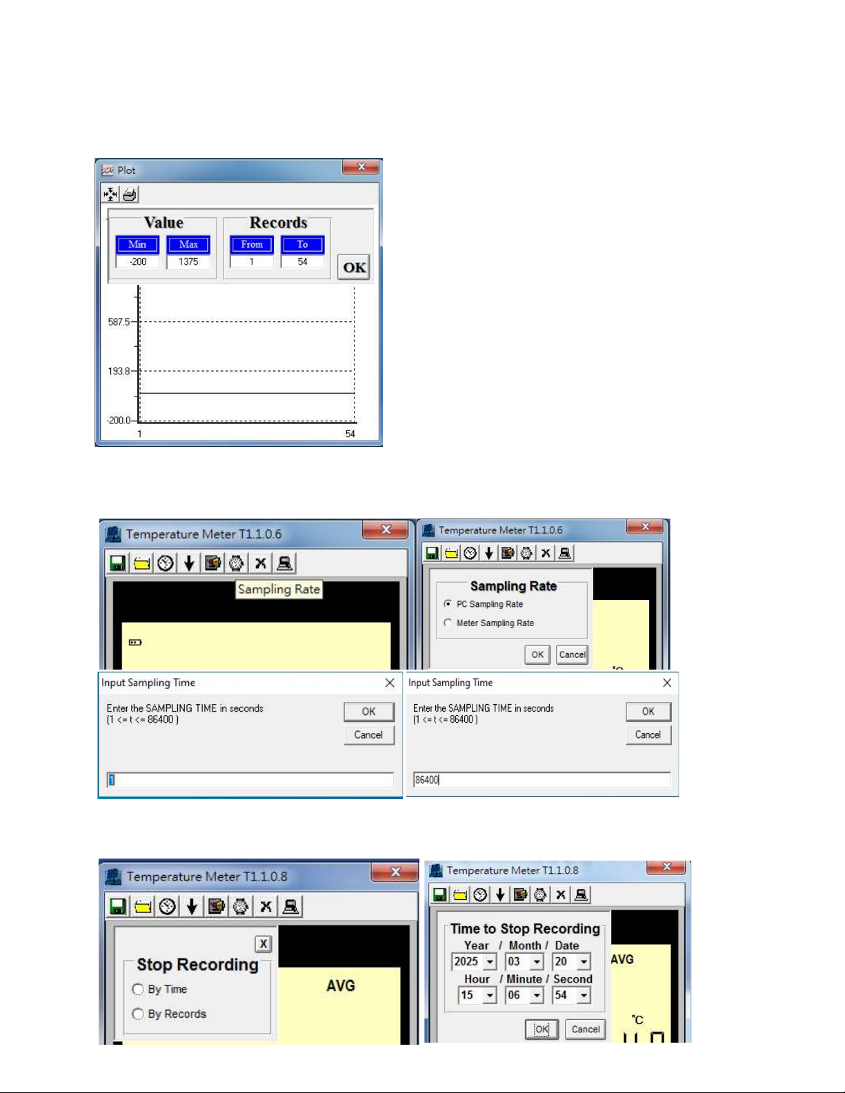
Change time and temperature range on the temperature chart
Change “record sampling time” (Min sample time 1 sec; Max sample time 86400sec)
Change “time to stop recording”
17
Page 18

8. General specifications
Display: 4-channel and 4-digit LCD
Unit: ℃ / ℉ / °K
Data hold (HOLD)
Auto-ranging
Backlight
Auto power (default 15 min) and disable auto power off
Maximum/minimum/mean value/measurement elapsed time
Alarm function
Overload display: “OL”
Input limit: Maximum input 24V DC or AC
Datalogging capacity 16,800 records
Save interval: 1 second~24 hour
Low battery detection
Battery: 1.5V×6 (LR03 SIZE AAA 1.5V)
Battery life: Approximately 100 hours
Operation temperature and humidity: 0°C to 50°C (32°F to 122°F), < 80%RH
Storage temperature and humidity:0°C to 50°C, relative humidity under 80%.
Weight: Approximately 330 grams
Dimensions: 168 (L) x 73 (W) x 35 (H) mm
The backlight will be continuously on if the meter is connected to the external power
supply
AC to DC Adaptor
External AC 100~240V to DC 9V/0.5A adaptor. (Please pay attention to the polarity)
Voltage: DC9V (9.0 ~ 15.0 VDC MAX)
Current: ≧1000mA。
Plug: The pin in the center connects to the positive electrode and the outer case is a
negative electrode
Diameter: 5.5mm; internal diameter: 2.1mm.
18
Page 19
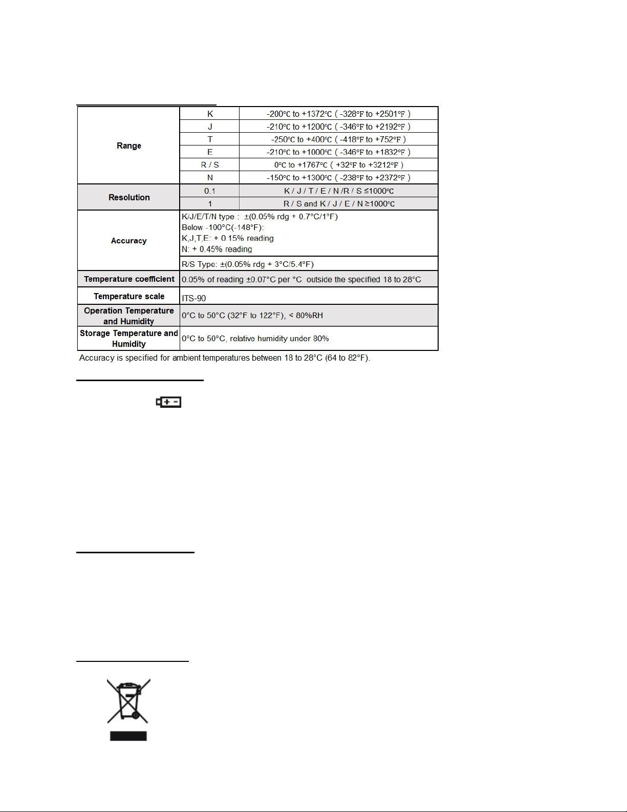
9. Electrical specifications
10. Maintenance or repair
When the When “ ” symbol is displayed on the LCD, it means that there is insufficient
power; please change the battery immediately in order to ensure its accuracy.
Do not place the meter in locations that have a high temperature, humidity or that are
exposed to direct sunlight.
Remember to turn off the power after usage; remove the battery if not used for a long
period of time in order to prevent battery leakage and causing damages to internal
components.
When the instrument failure, only by the authorized service provider or return the original
repair.
11. Battery replacement
Turn off the power.
Open the frame and battery cover at the back of the meter, remove the batteries.
Please insert a new AAA battery according to the polarities.
Put the battery cover and frame back in place.
12. End of life disposal
Note: This symbol indicates that the meter and its accessories must be
separated and processed properly.
19
 Loading...