

Page 1

User’s Guide
Shop online at
omega.com
e-mail: [email protected]
For latest product manuals:
omegamanual.info
MADE IN TAIWAN
HH126
RTD Data Logger Thermometer
Page 2

OMEGAnet®Online Service Internet e-mail
omega.com [email protected]
Servicing North America:
U.S.A.: Omega Engineering, Inc., One Omega Drive, P.O. Box 4047
ISO 9001 Certified Stamford, CT 06907-0047 USA
Canada: 976 Bergar
Laval (Quebec), Canada H7L 5A1
Toll-Free: 1-800-826-6342 TEL: (514) 856-6928
FAX: (514) 856-6886 e-mail: [email protected]
For immediate technical or application assistance:
U.S.A. and Canada: Sales Service: 1-800-826-6342/1-800-TC-OMEGA
Customer Service: 1-800-622-2378/1-800-622-BEST
Engineering Service: 1-800-872-9436/1-800-USA-WHEN
Mexico: En Español: 001 (203) 359-7803 FAX: (001) 203-359-7807
®
®
®
Servicing Europe:
Benelux: Managed by the United Kingdom Office
Czech Republic: Frystatska 184
733 01 Karviná, Czech Republic
Toll-Free: 0800-1-66342 TEL: +420-59-6311899
FAX: +420-59-6311114 e-mail: [email protected]
France: Managed by the United Kingdom Office
Toll-Free: 0800 466 342 TEL: +33 (0) 161 37 29 00
FAX: +33 (0) 130 57 54 27 e-mail: [email protected]
Germany/Austria: Daimlerstrasse 26
D-75392 Deckenpfronn, Germany
Toll-Free: 0 800 6397678 TEL: +49 (0) 7059 9398-0
FAX: +49 (0) 7056 9398-29 e-mail: [email protected]
United Kingdom: OMEGA Engineering Ltd.
ISO 9001 Certified
It is the policy of OMEGA Engineering, Inc. to comply with all worldwide safety and EMC/EMI
regulations that apply. OMEGA is constantly pursuing certification of its products to the European New
Approach Directives. OMEGA will add the CE mark to every appropriate device upon certification.
The information contained in this document is believed to be correct, but OMEGA accepts no liability for any
errors it contains, and reserves the right to alter specifications without notice.
WARNING: These products are not designed for use in, and should not be used for, human applications.
One Omega Drive, River Bend Technology Centre, Northbank
Irlam, Manchester M44 5BD England
Toll-Free: 0800-488-488 TEL: +44 (0)161 777-6611
FAX: +44 (0)161 777-6622 e-mail: [email protected]
Page 3

Introduction:
HH126 hand-held thermometer is the digital thermometer which uses the microprocessor.
The HH126 unit penetrates the IrDA output port and PC online (USB or RS232).
Use PC and USB port online have to select the IrDA-USB transmit wire.
Use PC and RS232 port online have to select the IrDA-RS232 transmit wire.
Accessories:
Common accessories:
4 1.5 V batteries
Housing x 1pcs
4PIN MINI DIN wire x 2pcs
Users manual x 1pcs
With PC on-line accessories:
Temp Monitor software users manual x 1pcs
IrDA-USB or IrDA-RS232 transmit wire x 1pcs
Temp Monitor software CD x 1pcs
1
Page 4

Security information:
Warning
To avoid electrical shock or personal injury, follow these guidelines:
•
Before using the thermometer inspect the case. Do not use the thermometer if it appears damaged.
Look for cracks or missing plastic. Pay particular attention to the insulation around the connectors.
•
Disconnect the RTD from the thermometer before opening the case.
•
When displays battery mark become ( ), and you hear a short buzzing sound,
replace the battery immediately, the possibility of false readings can lead to personal injury.
•
D
o not use the thermometer if it operates abnormally. Protection may be impaired. When in doubt,
have the thermometer serviced.
•
Do not operate the thermometer around explosive gas, vapor, or dust.
•
Do not exert the voltage to RTD or earth.
•
Do not take RTD direct measure generator set or equipment, intense electric shock possibly can
lead to personal injury.
•
Wh
en the thermometer cover opened, is sure not to use thermometer.
•
Do not to put thermometer in the microwave oven to measure temperature.
When RTD measure is high temperature or low temperature, you should be careful to avoid goods
•
because it can can lead to personal injury.
Caution
A caution identifies conditions and actions that may damage the meter or the equipment under test.
Use the proper RTD, function, and range for your thermometer.
•
Do not attempt to recharge the batteries.
•
To prevent explosion, do not throw batteries into a fire.
•
Follow local laws or regulations when disposing of batteries.
•
Match the + and - polarities of the battery with the battery case.
•
2
Page 5
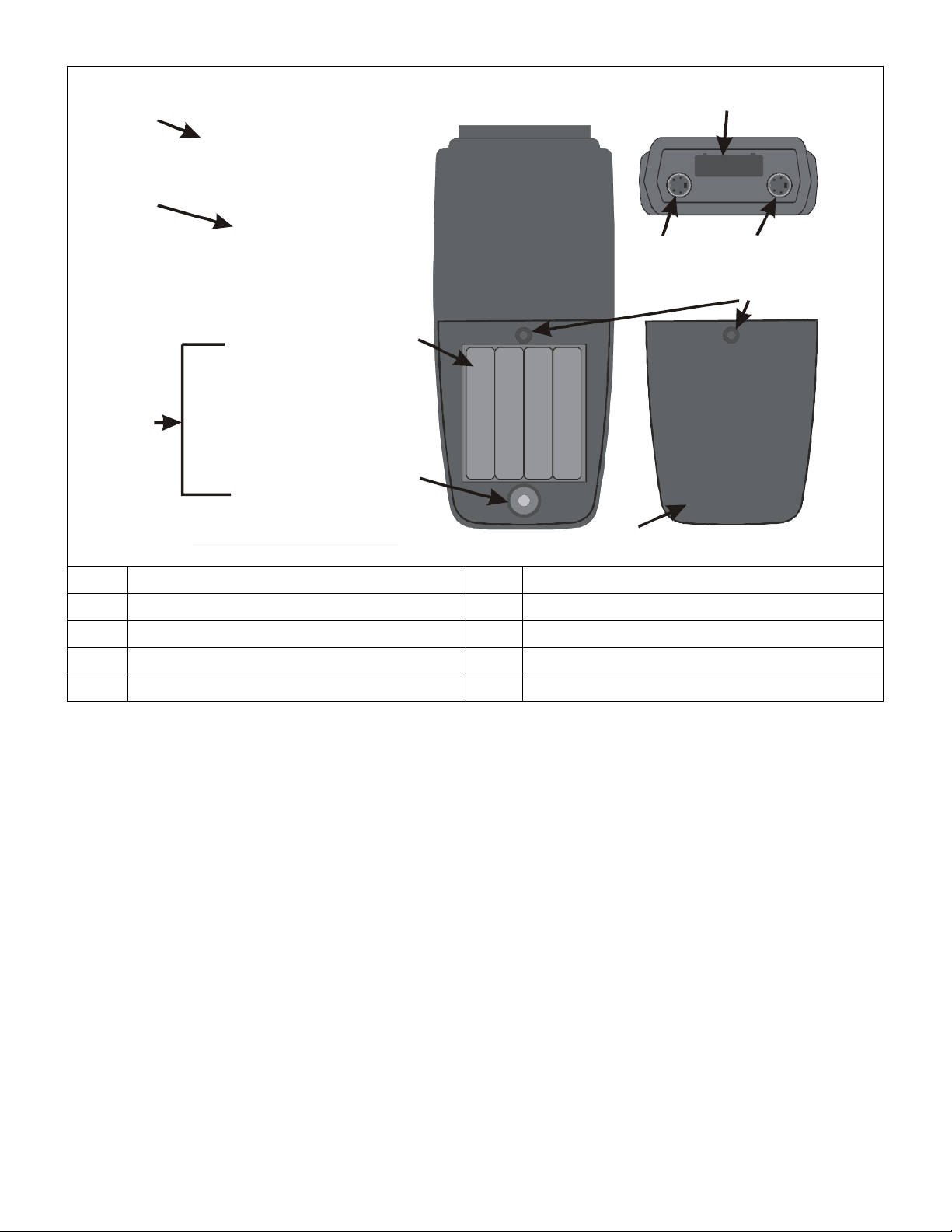
Names of parts:
T2
⑧
⑨
①
T1
②
③
④
⑤
⑦
⑩
⑥
① Housing ⑥ IrDA output port
② LCD display ⑦ T1- RTD input
③ Function control keys ⑧ T2-RTD input
④ Battery seat ⑨ Screw hole
⑤ Reset key ⑩ Battery cover
3
Page 6
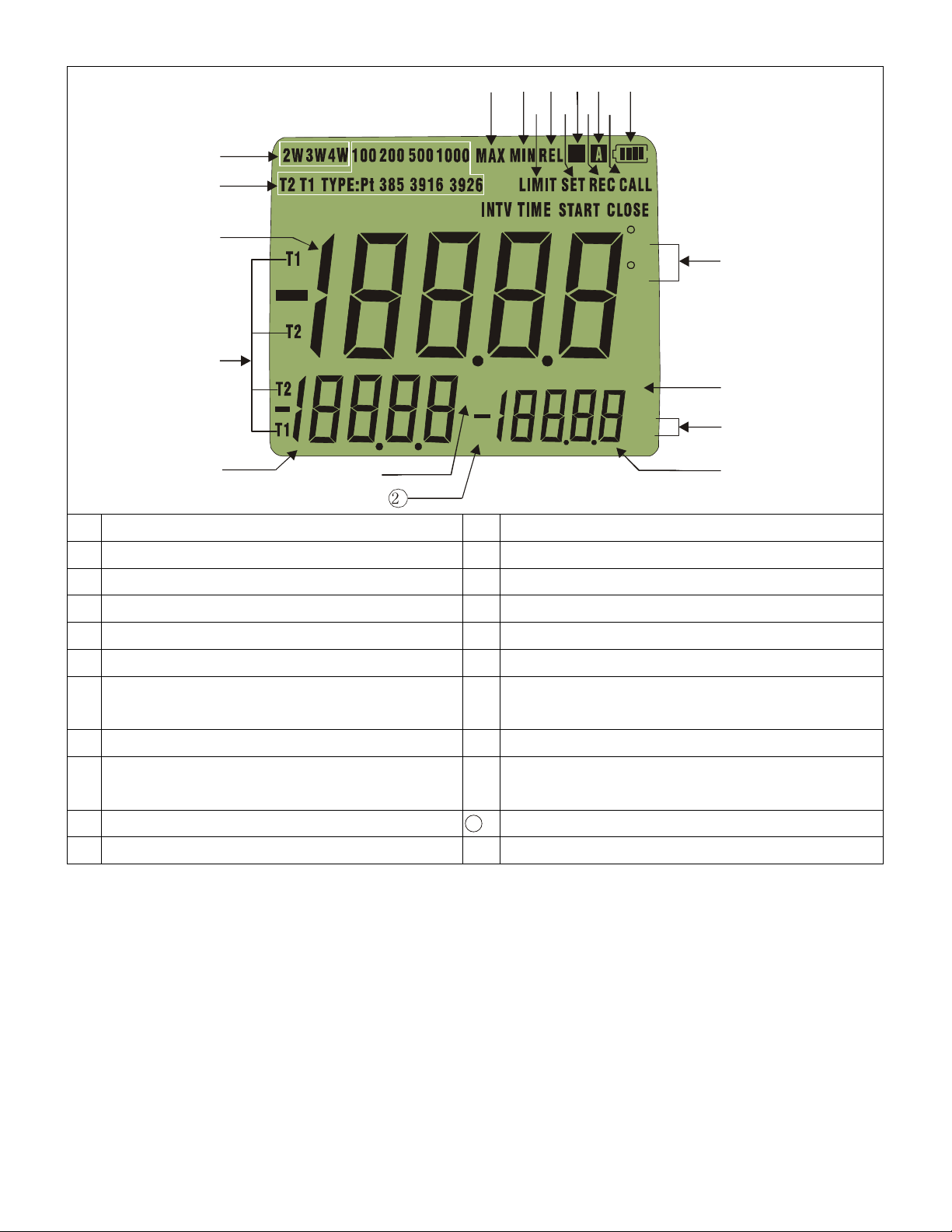
Display elements:
⑦
⑧⑨⑩
⑪⑫⑬⑭⑮
⑯
⑰
⑱⑲⑳
① Choose measurement way of RTD ⑫ Carry out record function
①
②
③
④
⑤
1
⑥
H
T1-T2
h m
d:m m s
C
F
y
:
:
② Choose T1, T2 measurement RTD types ⑬ 20 minutes auto power off
③ Main display ⑭ Examine recorded reading
④ Main, secondary display reading is T1 or T2 ⑮ Five sections of battery power instruction
⑤ Secondary display ⑯ Temperature unit
⑥ Main, secondary display maximum reading ⑰ Main display shows time's "year"
⑦ Main, secondary display minimum reading ⑱ Third display shows time's "hour:minute", or
"minute:second"
⑧
Main display carry out alarm function
⑨ Main display carry out relative reading , third
display shows relative reference reading
⑩ Carry out set function
⑪ Hold display reading
⑲
⑳ Third display shows “T1-T2” reading
21
4
Third display
Secondary display shows time’s “day”, ”month”
Page 7
Battery power indicator and replacement:
The battery power expressed by five sections of batteries marks. ( )
•
When battery mark shows ( ) and you hear a gap-like short buzzing sound, indicates the battery
•
power is weak, please immediately close unit and replace 1.5V batteries to ensure the measuring
accuracy.
•
When battery power is low, to keep thermometer normal operation, can automatically stop the
thermometer operation, and the main display will be show BATT and third display shows LO, after
lease immediately turn OFF unit and replace the 1.5V batteries and turn ON thermometer.
p
•
When replace battery, must use a cross screwdriver to open battery cover, after exchange four new 1.5V
batteries and lock battery cover.
Replace in front of the battery, please take RTD away from thermometer.
•
•
Replace in front of the battery, please note the battery polarity, cannot make a mistake.
When the thermometer is not in use, please takes out the battery, and avoid leaving in a high
•
temperature, wet place.
•
Replace battery if surpasses above for 30 seconds, the thermometer can automatic reset and directly
e
nter to calendar setting function.
Replace battery if thermometer display shows not to be normal, please open battery cover and
•
use the small screwdriver to press the Reset key, let thermometer reset and directly enter calendar
setting function.
Keys:
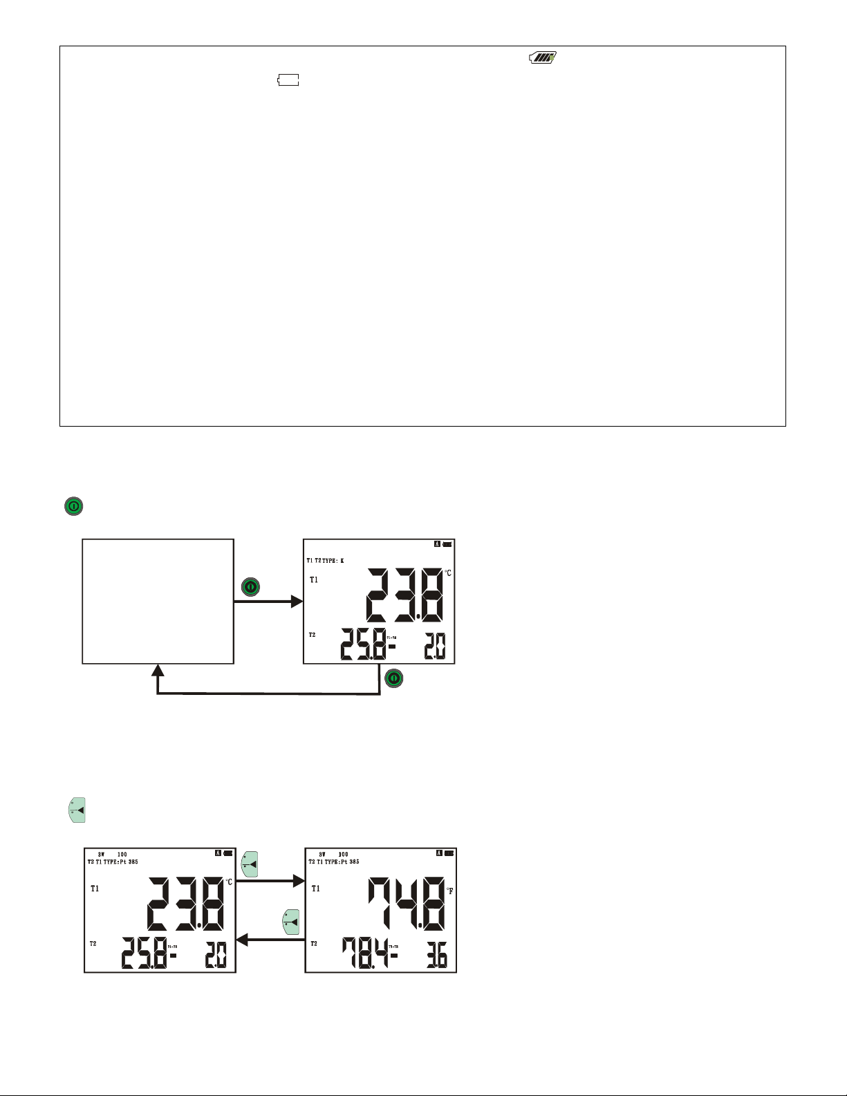
Power key: turn on/off thermometer. Auto power off function, after 20 minutes will auto power off.
Initial temperature unit is (°C), when you
turn power on, meter will keep last power
off state.
Dual inputs: secondary display shows T2
measuring value and third display shows
T1-T2 value.
C
Temperature unit key:
F
Choose temperature unit to be Centigrade ( ) or Fahrenheit ( ).
C
F
°C
°F
C
F
5
Page 8
MAX
MIN
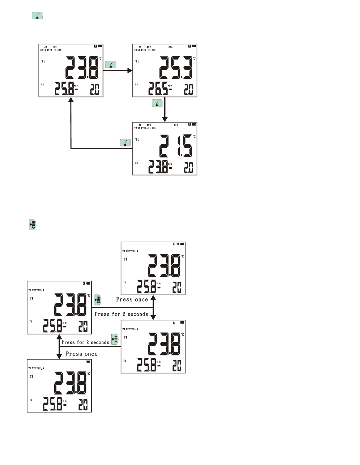
Maximum/minimum key: Main, secondary display shows (T1, T2) maximum/minimum value at same
time, third display shows (T1- T2) real time readings.
Hold readings key:
MAX
MIN
MAX
MIN
MAX
MIN
Hold LCD display readings.
Press once: Carry out/cancel hold readings
function.
Press for 2 seconds: Carry out/cancel hold
readings function and to carry out/cancel auto
power off function.
6
Page 9
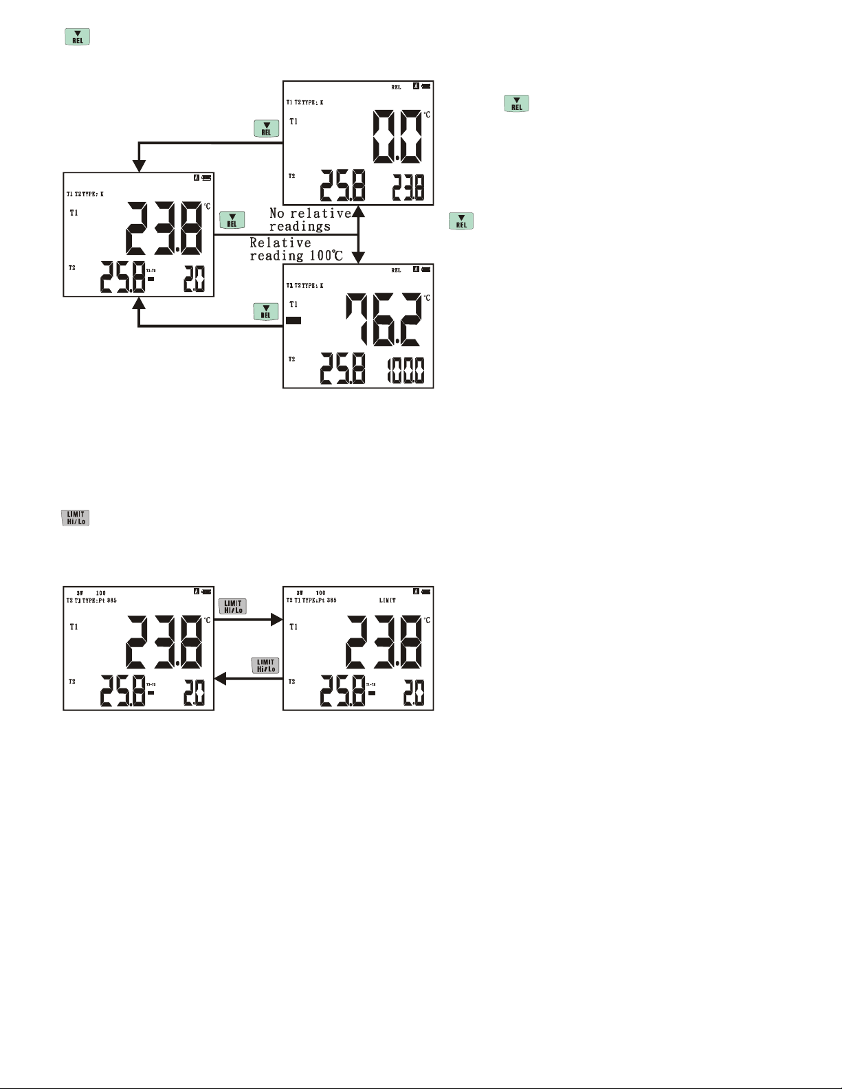
Relative readings key: Main display shows (T1 or T2 readings - relative readings), third display shows
While pushing
relative readings.
When not setting up relative readings: while
pushing key for main display shows (T1 or
T2) readings are the relative readings, it is show
in third display.
When setting up relative readings:
key, third display shows set up relative
readings.
Note: Set up operation of relative readings, please
consult the explanation of set up relative readings.
Alarm function key:
Main display shows (T1 or T2) readings greater than or smaller than (T1 or T2)
setting up critical high value or low value of alarm, the buzzer will send out alarm
sound continuously.
Note: Set up operation of alarm critical value,
e consult the explanation of set up alarm
pleas
critical value.
7
Page 10
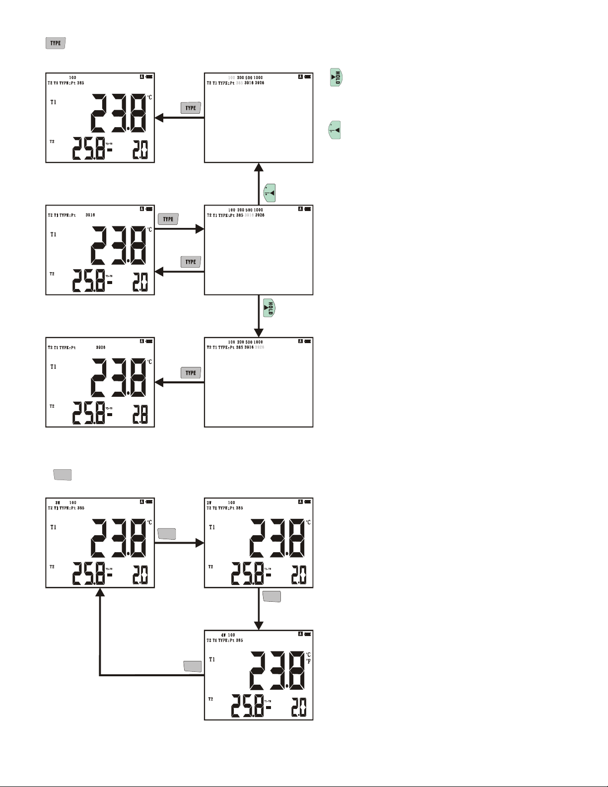
Choose types key of RTD: To choose types of RTD.
−>
−>
Press to move right one –figure that
−>−>
RTD type chosen.
C
−>
F
Press to move left one -figure that
RTD type chosen.
C
F
RTD
2/3/ 4W
2W/3W/4W option key of RTD: The input to choose RTD is 2W, 3W or 4W.
Note: 2W RTD is unable to use 3W or 4W to
measure. 3W RTD is unable to use 4W to
RTD
2/3/ 4W
measure.
2W and 3W Rtd’s will not be compensated
for extension wire resistance.
RTD
2/3/ 4W
Pt385 100 , increase 0.391 , nearly increase
Ω Ω
1°C/1.8°F errors.
Pt3916 100 , inc
Ω
rease 0.397 , nearly increase
1°C/1.8°F errors.
RTD
2/3/ 4W
Pt3926 100 , increase 0.398 , nearly increase
1°C/1.8°F errors.
Pt385 200 , increase 0.782 , nearly increase
Ω
Ω
1°C/1.8°F errors.
Pt385 500 , Increase 1.954 , nearly increase
°C
1 /1.8
Pt385 1000 , increase 3.91 , nearly increase
1°C/1.8°F errors.
8
Ω
errors.
°F
Ω
Ω
Ω
Ω
Ω
Ω
Page 11
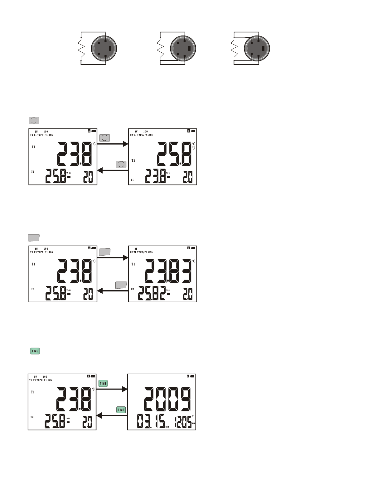
Wiring diagram of RTD input:
RTD
RTD
RTD
2W 3W 4W
T1 T2
T1, T2 exchange key
:
Main, secondary displays are exchanged (T1, T2) measure values.
T1 T2
T1 T2
RTD
Option key of resolution of RTD: Main, secondary display shows measurement values of RTD of among
0.1 /0.0 1
±
RTD
0.1 /0.0 1
200 (°C/°F), optional resolution is 0.1 or 0.01.
RTD
0.1 /0.0 1
Look over key of the perpetual calendar: Main display shows year, secondary display shows date:month,
third display shows hour: minute.
9
Page 12
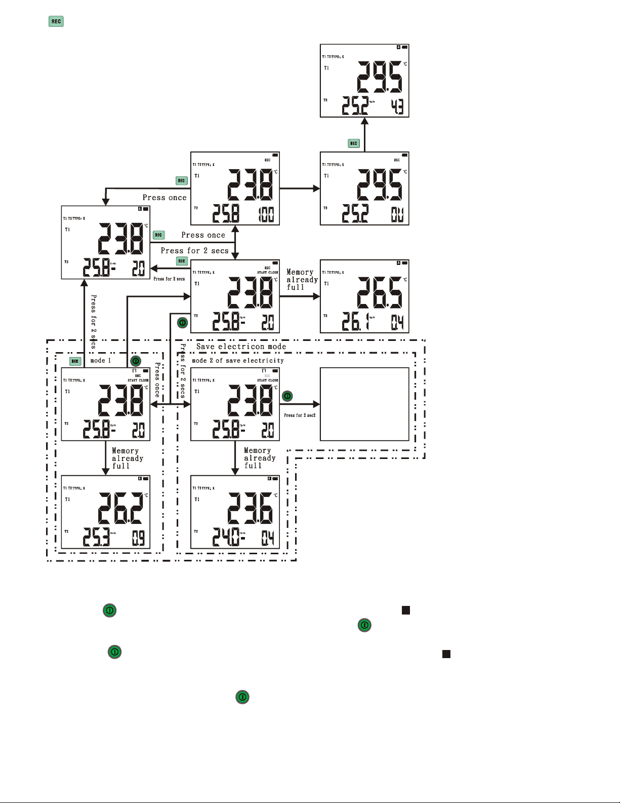
The data record key: The data record is divided into real time recording and scheduled receiving on page 15.
Set up the recording interval time from instructions on page 18.
To start recording in real
time press the (REC) button.
Data logging starts at the
interval set.
Quantity of data points
appears in third display.
To stop recording press
(REC) button.
Review logged data per
instructions on page 11.
When in the scheduled
record mode the following
electricity settings are
available.
Mode to save electricity is under order setting record: Need to set up ( INTV) interval time ±10 seconds. Can
increase the service time of order setting record.
press power key once>Enter mode 1 of save electricity
sleep state, will start MCU when measurement recorded.
,,,,
symbol will glimmer, MCU will enter the
Press power key again finishes mode of save
H
electricity 1.
press power key for 2 seconds>Enter mode 2 of save electricity, symbol and REC will
glimmer
,,,,
MCU will enter the sleep state
and close the peripheral drive circuit,
circuit when wanting to measurement record. If un
able to finish the function of order setting record
H
will start MCU and drive
under mode of save electricity 2, press power key 2 seconds to finish order setting record function.
10
Page 13
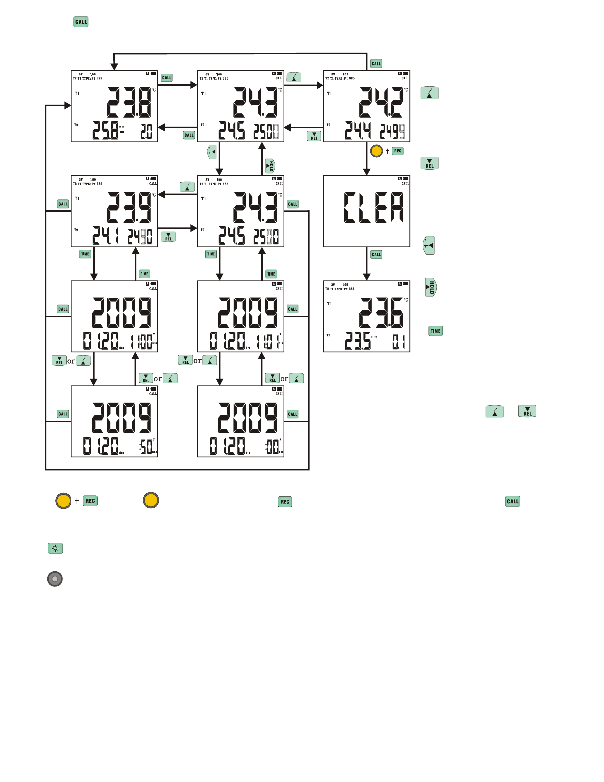
Press button to review recorded data.
Main, secondary display shows recorded data.
Recorded data on (T1, T2), third display shows the log of recorded data, if OU shows the memory is already
full.
MAX
MIN
MAX
MIN
>press once to look
over logged data, press and
hold can look over the
record data forward fast.
C
F
MAX
MIN
SET
>
press once to look
over next one logged
data, press and hold can look
over the record data
backward fast.
C
>
Press to move left
F
one-figure that adjusted.
>
Press to move right one
-figure that adjusted.
>>>>
Press once to look
over record time that the
MAX
MIN
MAX
MIN
MAX
MIN
MAX
MIN
record loggers, main display
shows year, secondary
display shows month, date,
third display shows hour:
minute.
MAX
Press or key
MIN
each time at this moment,
can circulate and change
third display shows hour:
minute or: second.
SET
>Press key first and then press key, carry out clear memory function, press key
SET
again, get back to measuring state.
ack light:
B
Open/close LCD back light, will close automatically after opening one minute.
Function key of reset:
the system will produce reset movement,
Take a cross screwdriver, unlock after pressing Reset key under the battery cover,
and will resume for the initial state, and enter the function that
set up the perpetual calendar.
Note: For set up operation method of perpetual calendar, please consult set up the perpetual calendar
e
xplanation.
11
Page 14
SET
C
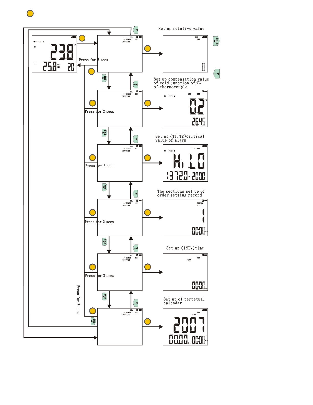
Set up the options function key: To enter the choice of the set up function required, carry out the set up
SET
function.
°C
°F
>Presses once to move
SET
right one-figure that set up
function chosen.
SET
°C
°F
F
>Press once to move left
one-figure that set up function
chosen.
SET
SET
SET
°C
°F
SET
Press SET once: Confirm
selection of the chosen function.
Press for 2 seconds: Leave the
chosen set up function.
°C
°F
SET
SET
°C
°F
SET
SET
°C
°F
SET
SET
12
Page 15
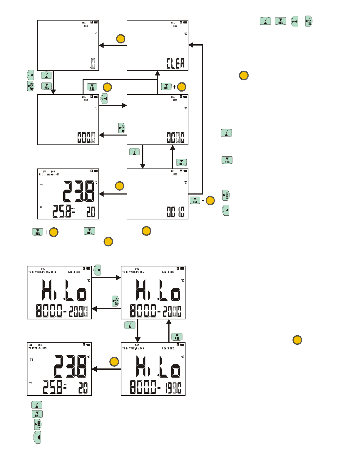
Set up relative value: When there is no setting up relative value the third display will show 0, begin to set up
after pressing , , , key.
MAX
MIN
C
F
Begin to set up from the setting up
SET
value when there is setting up value. Set
up range is limit it in the highest and
minimum temperature range that each
type RTD can be measured, adjust to
MAX
C
F
or
or
or
MIN
SET
C
F
SET
the set up value that you want then
press key to finish set up.
SET
Can set up the range in every type RTD:
t385 100Ω::::
P
-200 to 800°C (-328 to 1472°F)
Pt3916, Pt3926, Pt385 200Ω/500Ω/
1000Ω:
-200 to 600°C (-328 to 1112°F)
MAX
MIN
>
Press once to add one-figure
upward, a thousand-figure needs to be
MAX
MI N
accumulated by one hundred–figure.
>
Press once to decrease one-figure
>
downward, A thousand-figure needs to be
reduced downwards by one hundred–
SET
figure.
>
Press to move right one-figure.
SET
C
>
Press to move left one-figure.
F
SET
>
Press key then press key, third display shows CLEA mean to clear set up relative
value, press key again to
SET
SET
finish clearing.
Set up critical value of alarm: Set up main display shows (T1 or T2) critical value of the alarm, secondary
C
F
display shows high critical value of the alarm and
third display shows low critical value of the alarm.
Begun from the set up value directly when there is
set up critical value the alarm. While use not
choosing type function of RTD or temperature
unit to choose function and use not setting up
itical value of alarm, the high, low critical value
cr
MAX
MIN
of alarm shows that can be measured for every
type RTD highest and minimum temperature
value, adjust to you want and press key again
SET
to finish setting up.
SET
Can set up the range in every type RTD:
:
Pt385 100Ω:
::
-200 to 800°C (-328 to 1472°F)
Pt3916, Pt3926, Pt385 200Ω/500Ω/1000Ω
-200 to 600°C (-328 to 1112°F)
MAX
MIN
>
Press to add one-figure upward.
>
Press to minus one-figure downward.
>
Press to move right one-figure.
C
>
Press to move left one-figure.
F
13
Page 16
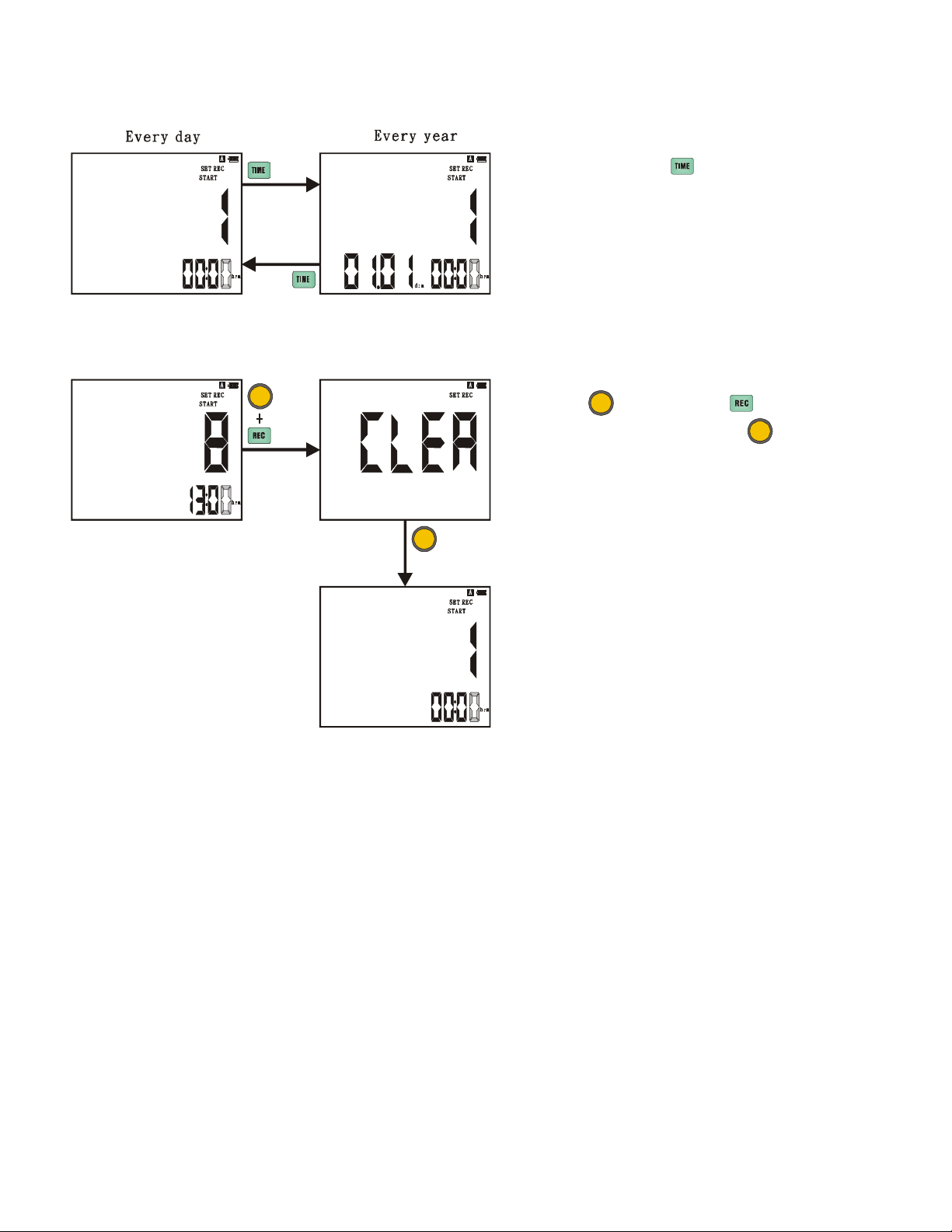
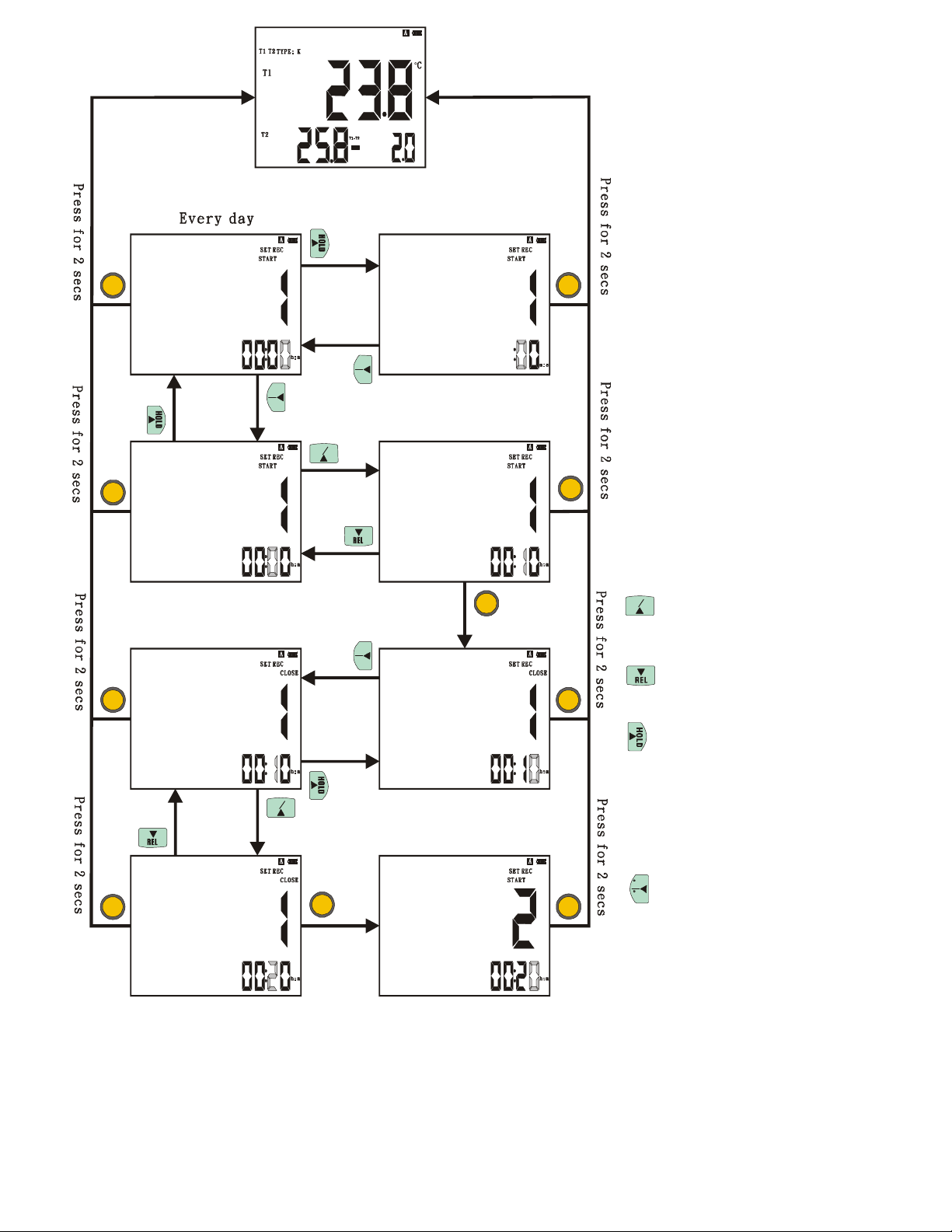
The sections set up of order setting record: Divide into the sections of order setting record (circulation of
every day) and (circulation of every year). Can only choose one to
set up, every kind can be set up for 9 sections at most.
Choose circulation of every day or circulation of
every year: Can press key to switch over and
choose circulation of every day or circulation of
every year under not finishing the set up in any
ection.
s
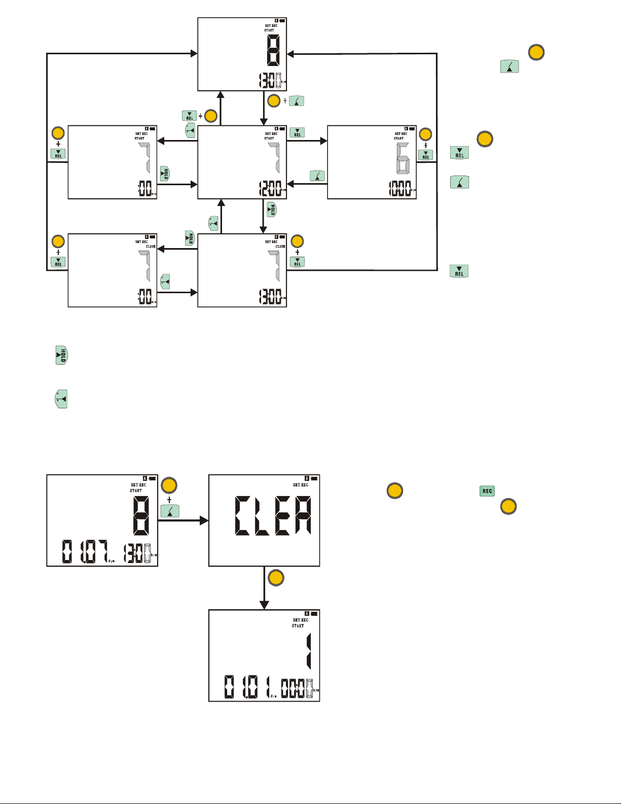
To delete the set up sections of circulation of every
SET
day: Press key then press key, when main
display shows CLEA then press key to finish
SET
SET
deleting.
SET
14
Page 17
SET
°C
°F
°C
°F
MAX
MIN
SET
SET
°C
°F
SET SET
MAX
MIN
SET
SET
SET
SET
SET
The order setting of circulation of
every day: A day 24 hours from
(00:00:00) 0 hour 0 minute 0
second to (23:59:59) 23 hours 59
minutes 59 seconds, at most can
set up 9 sections from 1 to 9 that
shows in main display. Symbol
START represents sets up the
beginning record time of section.
Symbol CLOSE represents set
up the end record time of section.
Need from small to big when to
set up sections of order setting, at
the same time the set up time of
e
ach section can not overlap and
repeat. It will be unable to finish
setting up to violate the above
rule of setting up. After finishing
sections of set up order setting
record, after carrying out, unless
the capacity of memory has been
already full or to cancel the
function of order setting,
repeated execution that will be
incessant every day.
MAX
MIN
>
Press to add one-figure
upward.
>
Press to minus one-figure
downward.
>Press to move right one
-figure. When the -figure of
adjusted in hour:minute (??:??)
that the most right –figure,
press again turn into: second
(:??).
C
F
>
Press to move left one
-figure. When the figure of
adjusted in: second (:??) that the
most left –figure, press again turn
into hour: minute (??:??).
To start order setting scheduled data logging press and hold (REC)
for 2 seconds. Display will show REC, START, and CLOSE.
START or CLOSE will only appear during the section presently
active. When complete data can be viewed by using review mode
on page 11.
15
Page 18
press key then press
function when the first set
SET
SET
SET
SET
Inquire about set up
sections of circulation of
every day: Press key
then press key, main
MAX
SET
MIN
display glimmers shows
MAX
MIN
SET
SET
C
F
sections of order setting
inquired, wish to leave
the inquire function,
SET
SET
key.
MAX
MIN
MAX
MIN
>
Press once to
inquire the set up sections
C
F
will add 1, there is no
function when the last
one set up section.
>
C
F
inquire the set up sections
Press once to
will minus 1, there is no
up section.
>>>>
At start time (START) that inquire the set up sections to press once, will turn into stop time (CLOSE).
Press once in stop time (CLOSE), the third display shows hour: minute (??:??) will turn into: second
(:??).
C
>>>>At stop time (CLOSE) that inquire the set up sections to press once, will turn into start time (START).
F
Press once in start time (START), the third display shows hour: minute (??:??) will turn
(
:??).
into: second
To delete the set up sections of circulation of every
MAX
SET
MIN
year:
Press key then press key, while main
display shows CLEA then to press key to
SET
finish deleting.
SET
16
Page 19
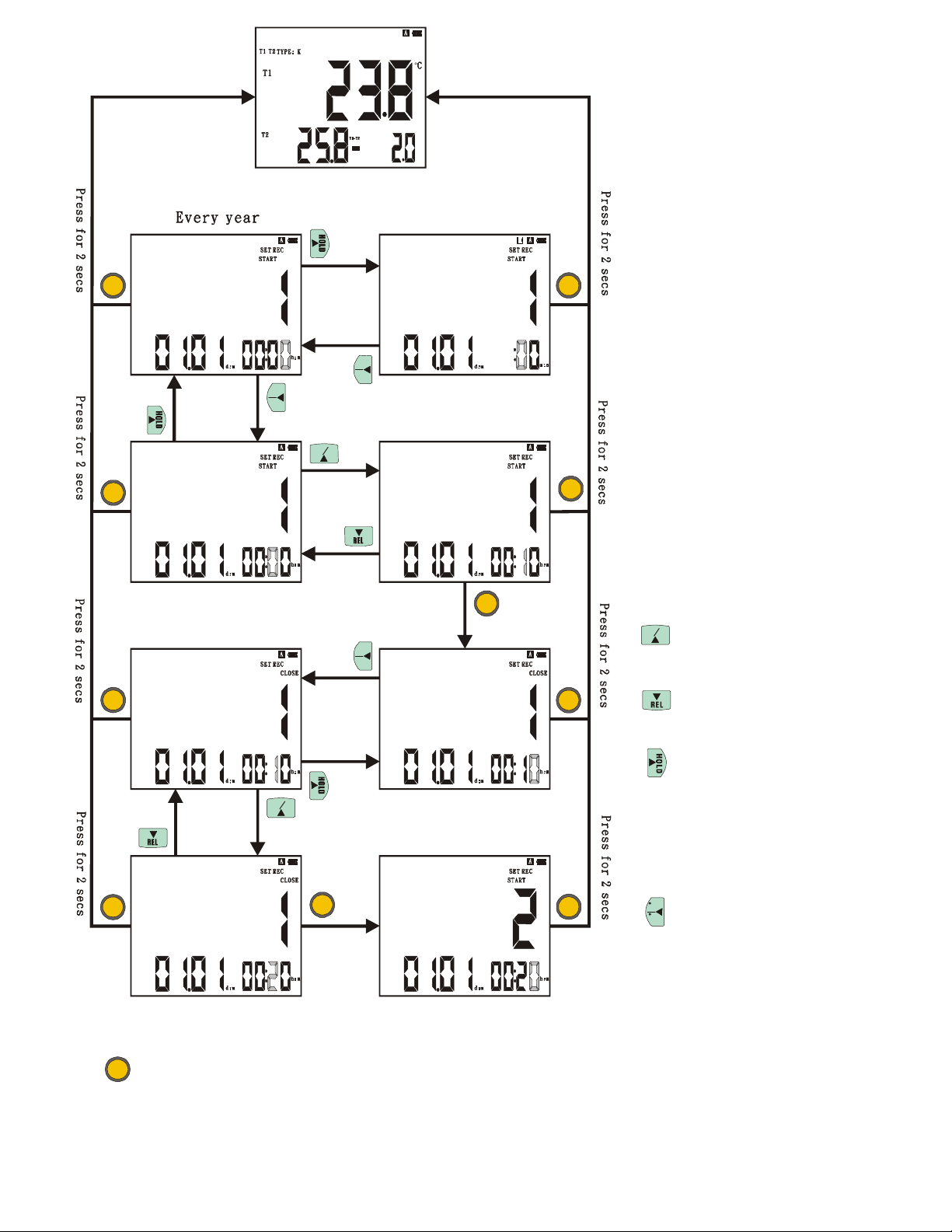
The order setting of circulation of
every year:
One year is divided
into 12 months, a day 24 hours
from (00:00:00) 0 hour 0 minute
0 second to (23:59:59) 23 hours
59 minutes 59 seconds, at most
can set up 9 sections from 1 to 9
that shows in main display.
Symbol START represents the
beginning record time of section.
Symbol CLOSE represents the
SET
SET
end recordtime of section.
Need from small to big when
setting up sections of order
setting, at the same time the set
°C
°F
°C
°F
u
p time of each section can not
overlap and repeat. It will be
unable to finish setting up to
violate the above rule of setting
MAX
SET
MIN
SET
up. After finishing sections of set
up order setting record, after
carrying out, unless the capacity
of memory has been already full
or to cancel the function of order
setting, repeated execution that
will be incessant every year.
SET
°C
°F
MAX
Press to add one-figure
>
MIN
upward.
SET
SET
Press to minus one-figure
>
downward.
>
Press to move right
MAX
MIN
one-figure. When the -figure
of adjusted in hour: minute
(??: ??) that the most rightfigure, press again turn into:
second (: ??).
SET
SET
SET
C
F
> Press to move left one
-figure that adjusted. When the
-figure of adjusted in: second (:??)
that the most left-figure, press
again turn into hour: minute
(??: ??).
SET
>
Press once to confirm set up, press for 2 seconds to leave the set up f
unction.
17
Page 20
SET
SET
SET
MAX
SET
SET
C
F
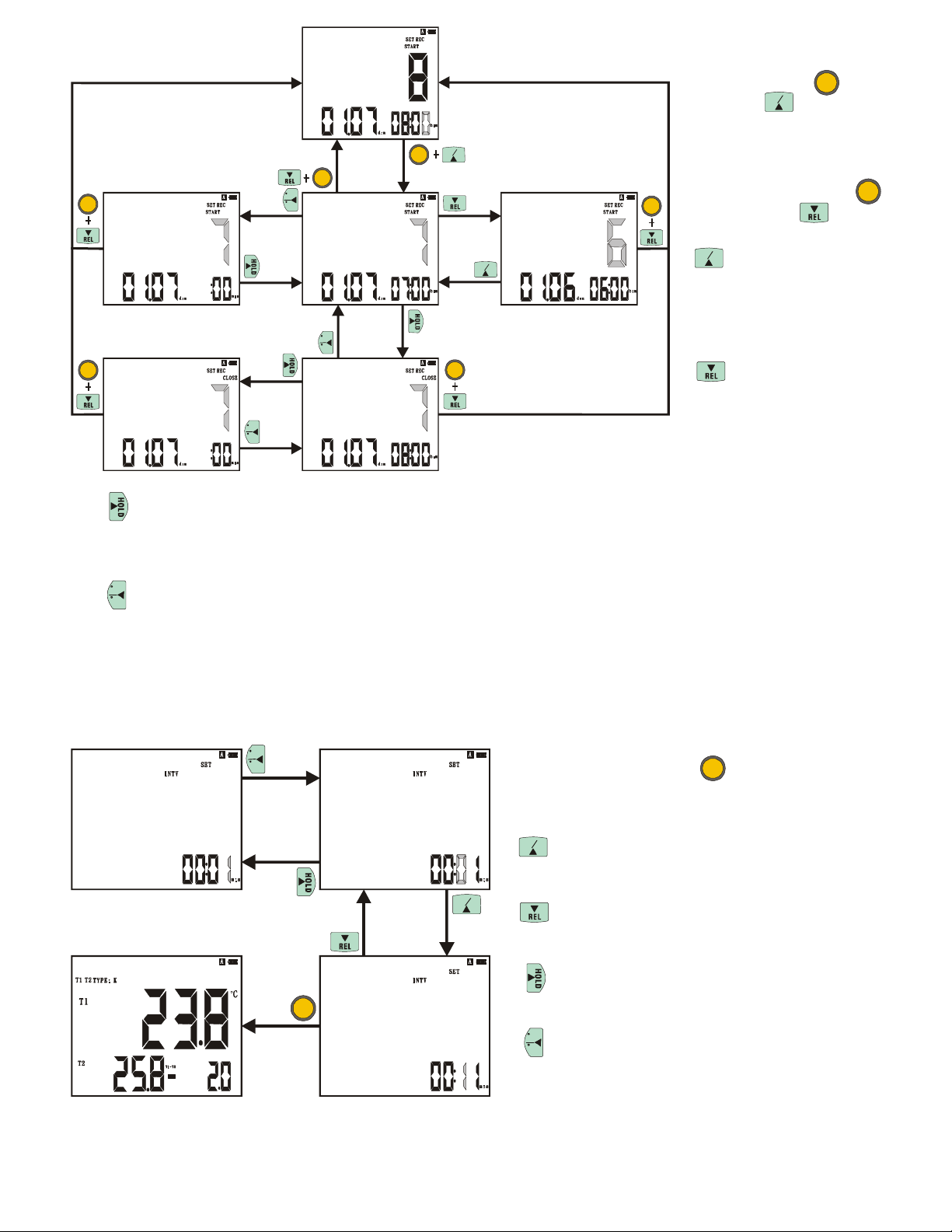
>At start time (START) that require the set up sections to press once, will turn into stop time
(CLOSE). Press once in stop time (CLOSE), the third display shows hour: minute (??:??) will
turn into: second (:??).
C
>
At stop time (CLOSE) that require the set up sections to press once, will turn into start time
F
(START). Press once in start time (START), the third display shows hour: minute (??:??) will
turn into:
second (:??).
Set up interval time of record:
C
F
Inquire about set up
sections of circulation of
every year: Press key
MAX
then press key, main
MIN
display glimmers shows
MAX
MIN
SET
SET
C
F
MAX
MIN
sections of order setting
inquired, wish to leave the
inquire function, press
SET
key then press key.
MAX
MIN
> Press once to
inquire the set up sections
will add 1, there is no
C
F
SET
function when the last one
set up section.
>
Press once to
inquire the set up sections
will minus 1, there is no
function when the first
up section
.
The interval time of record, minimum interval time is one second, the biggest
interval time is 59 minutes and 59 seconds, adjust
value you want and press key to finish
setting up to.
MAX
−>
MIN
Press to add one-figure upward.
MI N
−>
Press to minus one-figure downward.
set
−> Press to move right one-figure.
SET
C
F
−>Press to move left one-figure.
18
Page 21
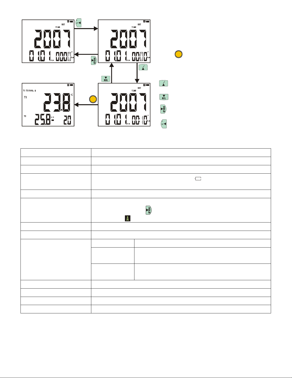
The time to set up of perpetual calendar: Main display shows year, the adjust range is from 2000 to
tery power is
Approximately 750 hours (interval = 15 minutes)/alkaline
Approximately 6 months (interval = 15 minutes)/alkaline
MI N
C
F
2099, secondary display shows date. month (xx.
xx), Third display shows hour: minute (24 hours
system). The adjust range from (00:00) 0 hour 0
minute to (23:59) 23 hours 59 minutes. Adjust to
set up value the effective date that you want then
SET
MAX
to press key to finish setting up. If ineffective
time of date, need to adjust to time of effective
d
ate could be left and set up.
MAX
MIN
>
Press to add one-figure upward.
>
SET
Press to minus one-figure downward.
>
Press to move right one-figure.
C
>Press to move left one-figure.
F
General specifications:
Display
4 1/2 digit crystal display, max display 19999
Polarity indicator No indicator in positive, negative indicator “-”
Overload indicator Positive overload show "OL", negative overload show “-OL”
Low power indicator When five sections of batteries mark show( ), expressed bat
run low.
Power UM-4 /1.5V batteries x 4pcs
Auto power off
The pressed key use has not reached 20 minutes the battery power will be
turned off, hold down key for 3 seconds to cancel auto power off
function, and mark of display will be disappeared.
Reading renewal 4 times/sec
Data logger Every channel 9999 loggers at most.
Battery life
General mode Approximately 210 hours/alkaline battery
Mode 1 of save
electricity
battery
Mode 2 of save
Operating temperature
Storage temperature
electricity
0 to -50°C (32 to 122°F), <80% RH
-10 to -60°C (-4 to 140°F), <70% RH
battery
Dimension 164 L x 76 W x 32 mm H (164 L x 76 W x 32 mm H)
Weight Approximately 415 g (0.916) (includes batteries)
19
Page 22

Electrical specifications:
Measurement
range
Resolution
Accuracy
Temperature
coefficient
Temperature
scale
Accuracy is specified for ambient temperatures between 18°C (64°F) and 28°C (82°F). The above
specifications do not include error of RTD.
RTD
Pt3916, Pt3926, Pt385 100Ω/200Ω/500Ω/1000Ω:
【
500Ω/1000Ω add 0.45% of reading】
0.01% of reading 0.03°C/°C 0.06°F per °F outside the specified 18 to 28°C (64 to
82°F) range 【below -100°C (-148°F) add 0.04% of
reading, Pt385 500Ω/1000Ω add 0.08% of reading】
ITS-90
Pt385 100Ω: -200 to 800°C (-328 to 1472°F)
Pt3916, Pt3926, Pt385 200Ω/500Ω/1000Ω: -200 to 600°C (-328 to 1112°F)
Pt3916, Pt3926, Pt385 200Ω/500Ω/1000Ω: <+200°C/°F
0.01
Pt3916, Pt3926, Pt385 200Ω/500Ω/1000Ω: <–200°C/°F
Pt3916, Pt3926, Pt385 200Ω/500Ω/1000Ω: <+200°C/°F
Pt3916, Pt3926, Pt385 200Ω/500Ω/1000Ω: <–200°C/°F
±【
0.05% reading+ 0.3°C (0.6°F】
below-100°C (-148°F) Pt3916, Pt3926, Pt385 100Ω/200Ω
Pt3916, Pt3926, Pt385 100Ω/200Ω
add 0.15% of reading, Pt385
20
Page 23

WARRANTY/DISCLAIMER
OMEGA ENGINEERING, INC. warrants this unit to be free of defects in materials and workmanship for a
period of 13 months from date of purchase. OMEGA’s WARRANTY adds an additional one (1) month
grace period to the normal one (1) year product warranty to cover handling and shipping time. This
ensures that OMEGA’s customers receive maximum coverage on each product.
If the unit malfunctions, it must be returned to the factory for evaluation. OMEGA’s Customer Service
Department will issue an Authorized Return (AR) number immediately upon phone or written request.
Upon examination by OMEGA, if the unit is found to be defective, it will be repaired or replaced at no
charge. OMEGA’s WARRANTY does not apply to defects resulting from any action of the purchaser,
including but not limited to mishandling, improper interfacing, operation outside of design limits,
improper repair, or unauthorized modification. This WARRANTY is VOID if the unit shows evidence of
having been tampered with or shows evidence of having been damaged as a result of excessive corrosion;
or current, heat, moisture or vibration; improper specification; misapplication; misuse or other operating
conditions outside of OMEGA’s control. Components in which wear is not warranted, include but are not
limited to contact points, fuses, and triacs.
OMEGA is pleased to offer suggestions on the use of its various products. However,
OMEGA neither assumes responsibility for any omissions or errors nor assumes liability for any
damages that result from the use of its products in accordance with information provided by
OMEGA, either verbal or written. OMEGA warrants only that the parts manufactured by the
company will be as specified and free of defects. OMEGA MAKES NO OTHER WARRANTIES OR
REPRESENTATIONS OF ANY KIND WHATSOEVER, EXPRESSED OR IMPLIED, EXCEPT THAT OF
TITLE, AND ALL IMPLIED WARRANTIES INCLUDING ANY WARRANTY OF MERCHANTABILITY
AND FITNESS FOR A PARTICULAR PURPOSE ARE HEREBY DISCLAIMED. LIMITATION OF
LIABILITY: The remedies of purchaser set forth herein are exclusive, and the total liability of
OMEGA
indemnification, strict liability or otherwise, shall not exceed the purchase price of the
co mponent up on which liabi lity i s based. In no event shall OMEGA be liable fo r
consequential, incidental or special damages.
CONDITIONS: Equipment sold by OMEGA is not intended to be used, nor shall it be used: (1) as a “Basic
Component” under 10 CFR 21 (NRC), used in or with any nuclear installation or activity; or (2) in medical
applications or used on humans. Should any Product(s) be used in or with any nuclear installation or
activity, medical application, used on humans, or misused in any way, OMEGA assumes no responsibility
as set forth in our basic WARRANTY/DISCLAIMER language, and, additionally, purchaser will indemnify
OMEGA and hold OMEGA harmless from any liability or damage whatsoever arising out of the use of the
Product(s) in such a manner.
with r
espect to this order, whether based on contract, warranty, negligence,
RETURN REQUESTS/INQUIRIES
Direct all warranty and repair requests/inquiries to the OMEGA Customer Service Department. BEFORE
RETURNING ANY PRODUCT(S) TO OMEGA, PURCHASER MUST OBTAIN AN AUTHORIZED RETURN
(AR) NUMBER FROM OMEG A’S CUS T O M ER SE RVIC E DEPA RTM E N T (IN ORDE R TO AVOID
PROCESSING DELAYS). The assigned AR number should then be marked on the outside of the return
package and on any correspondence.
The purchaser is responsible for shipping charges, freight, insurance and proper packaging to prevent
breakage in transit.
FOR WARRANTY
following information available BEFORE
contacting OMEGA:
1. Purchase Order number under which the product
was PURCHASED,
2. Model and serial number of the product under
warranty, and
3. Repair instructions and/or specific problems
relative to the product.
OMEGA’s policy is to make running changes, not model changes, whenever an improvement is possible. This affords
our customers the latest in technology and engineering.
OMEGA is a registered trademark of OMEGA ENGINEERING, INC.
© Copyright 2011 OMEGA ENGINEERING, INC. All rights reserved. This document may not be copied, photocopied,
reproduced, translated, or reduced to any electronic medium or machine-readable form, in whole or in part, without the
prior written consent of OMEGA ENGINEERING, INC.
RETURNS, please have the
FOR NON-WARRANTY REPAIRS,
for current repair charges. Have the following
information available BEFORE contacting OMEGA:
1. Purchase Order number to cover the COST
of the repair,
2. Model and serial number of the product, and
3. Repair instructions and/or specific problems
relative to the product.
consult OMEGA
Page 24

Where Do I Find Everything I Need for
Process Measurement and Control?
OMEGA…Of Course!
Shop online at omega.com
SM
TEMPERATURE
Thermocouple, RTD & Thermistor Probes, Connectors, Panels & Assemblies
Wire: Thermocouple, RTD & Thermistor
Calibrators & Ice Point References
Recorders, Controllers & Process Monitors
Infrared Pyrometers
PRESSURE, STRAIN AND FORCE
Transducers & Strain Gages
Load Cells & Pressure Gages
Displacement Transducers
Instrumentation & Accessories
FLOW/LEVEL
Rotameters, Gas Mass Flowmeters & Flow Computers
Air Velocity Indicators
Turbine/Paddlewheel Systems
Totalizers & Batch Controllers
pH/CONDUCTIVITY
pH Electrodes, Testers & Accessories
Benchtop/Laboratory Meters
Controllers, Calibrators, Simulators & Pumps
Industrial pH & Conductivity Equipment
DATA ACQUISITION
Data Acquisition & Engineering Software
Communications-Based Acquisition Systems
Plug-in Cards for Apple, IBM & Compatibles
Data Logging Systems
Recorders, Printers & Plotters
HEATERS
Heating Cable
Cartridge & Strip Heaters
Immersion & Band Heaters
Flexible Heaters
Laboratory Heaters
ENVIRONMENTAL
MONITORING AND CONTROL
Metering & Control Instrumentation
Refractometers
Pumps & Tubing
Air, Soil & Water Monitors
Industrial Water & Wastewater Treatment
pH, Conductivity & Dissolved Oxygen Instruments
M4723/0911
 Loading...