

Page 1
MAN0837-03 ADC107/207 PAGE 1
+/-10V Analog Input Module
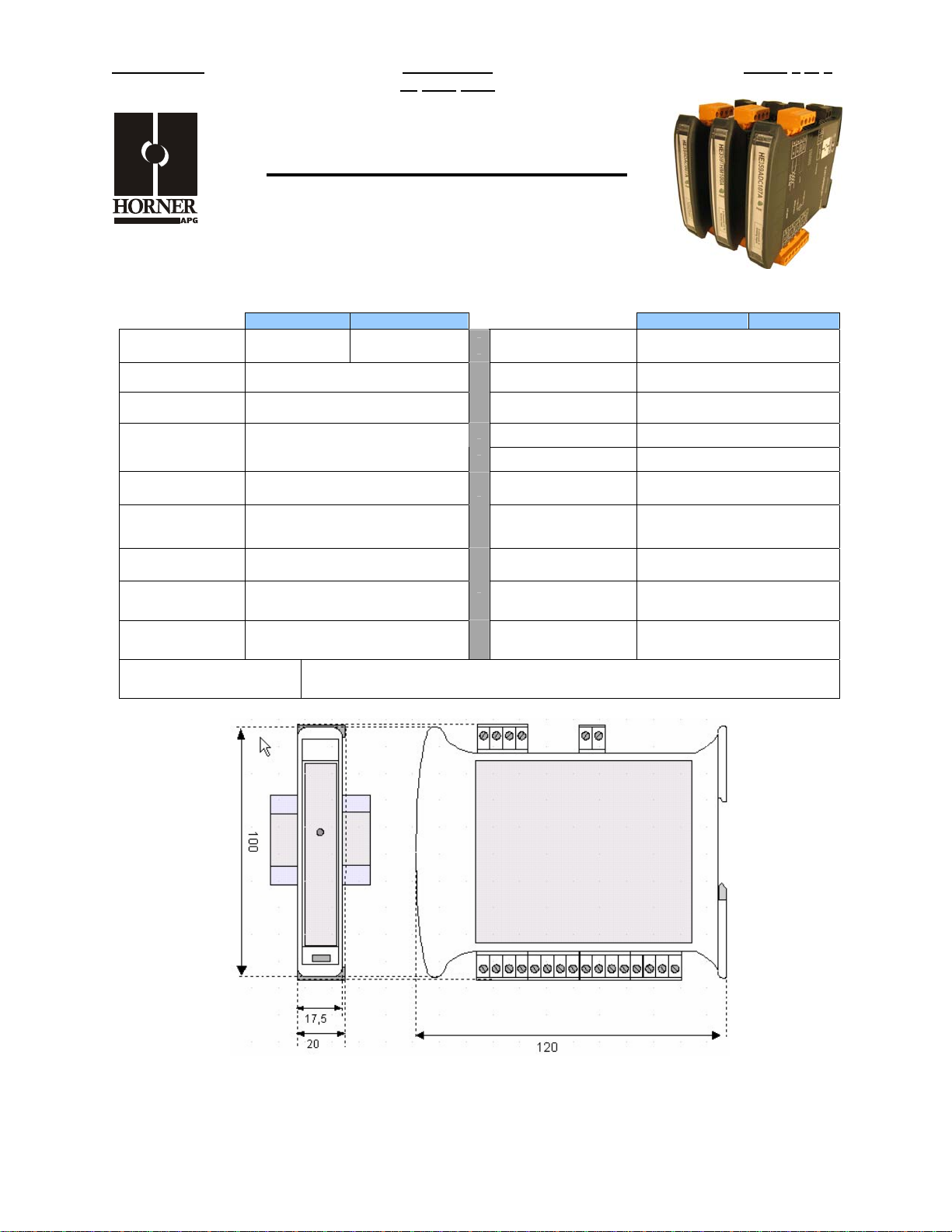
HE359ADC107 / HE359ADC207
SmartMod
16-Bit Resolution
1 SPECIFICATIONS
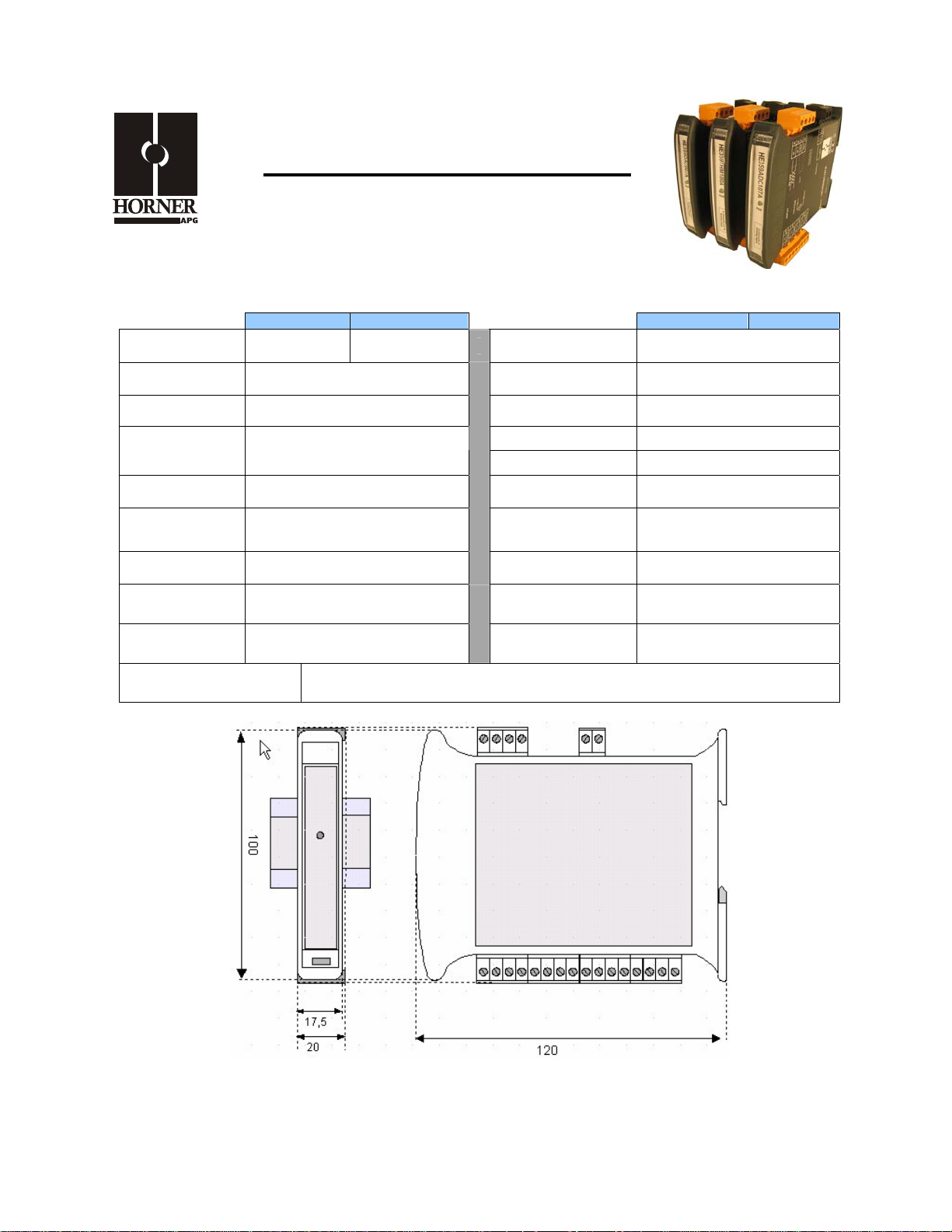
ADC107 ADC207 ADC107 ADC207
Number of
Channels
Input Ranges
Resolution Approximately 16-Bit Storage Temp.
Input Impedance 1MOhm
Linearity +/-0.1% Dimensions WxHxD
External Power
Supply Voltage
Required Power
(Steady State)
Required Power
(Inrush)
Isolation
4 8
+/-10V
10-30Vdc
30mA @ 24Vdc, typical
Negligible
2000Vac for 60 seconds
(Input/Power & Input/Comms)
Conversion Time
(PLC Update Rate)
Terminal Type Screw Type, Removable
Operating Temp.
Relative Humidity 5 to 95% Non-condensing
Weight 150g (6 oz.)
Communications
Default Comms.
Parameters
Supported Modbus
Commands
Determined by
Communications w/OCS
-40° to 85° Celsius
-10° to 60° Celsius
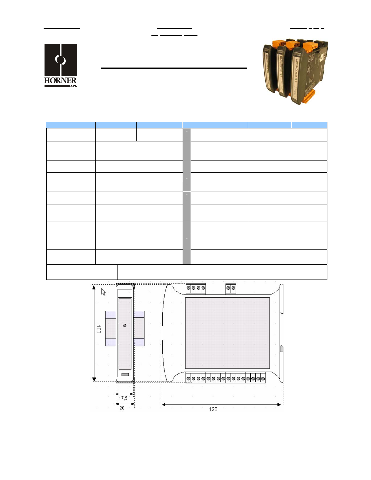
17.5mm x 100mm x 120mm
0.69” x 3.94” x 4.72”
Modbus/RTU (binary)
RS-485 half duplex
38400 baud, N, 8, 1, no h/s
Default Modbus ID 1
1,2,3,4,5,6,8,15,16
CE & UL Compliance See Compliance Table at http://www.heapg.com/Support/compliance.htm
Dimensions in inches are 0.69”W x 3.95”H x 4.72”D
Note: Number of I/O terminal connections vary from model to model
Page 1 of 6
Page 2
PAGE 2 ADC107/207 MAN0837-03
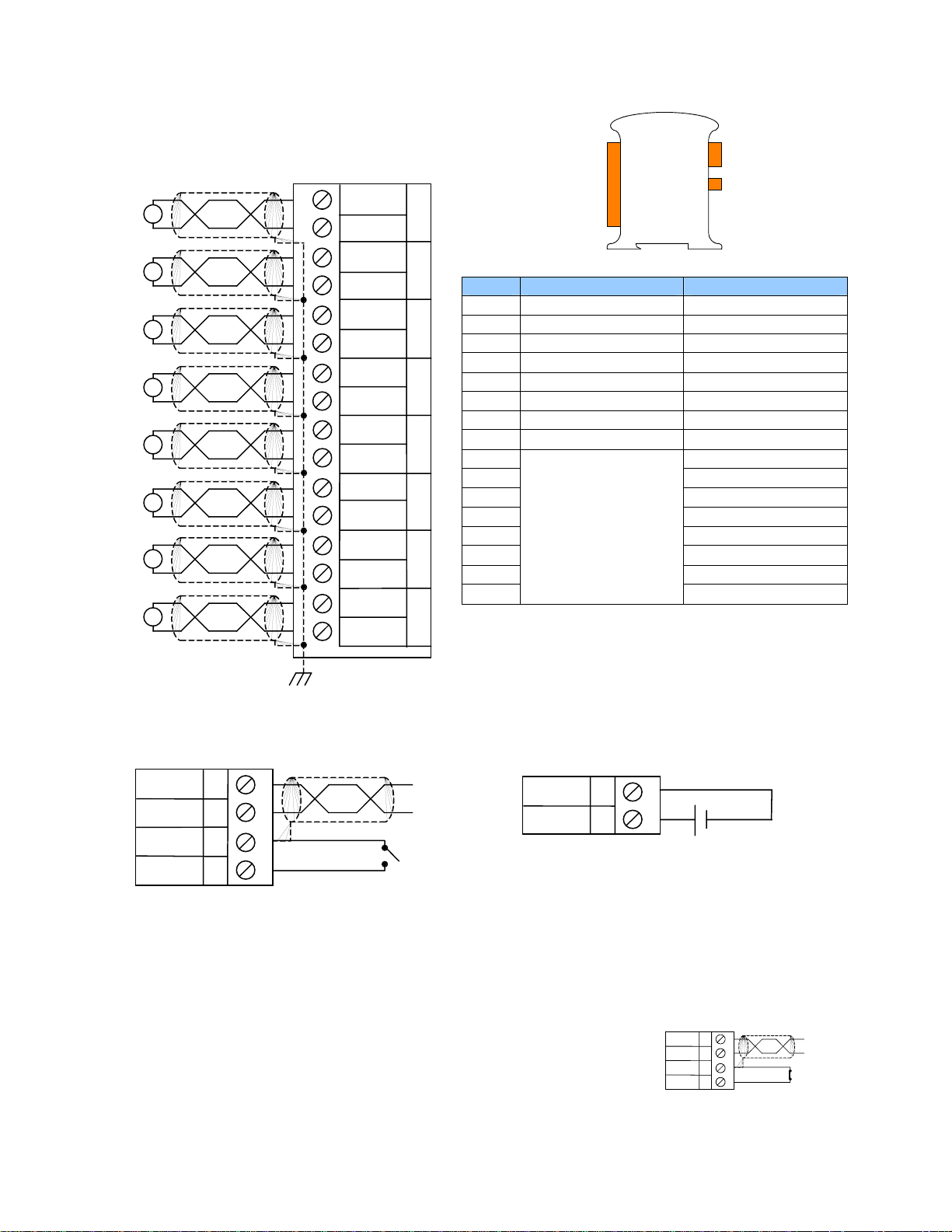
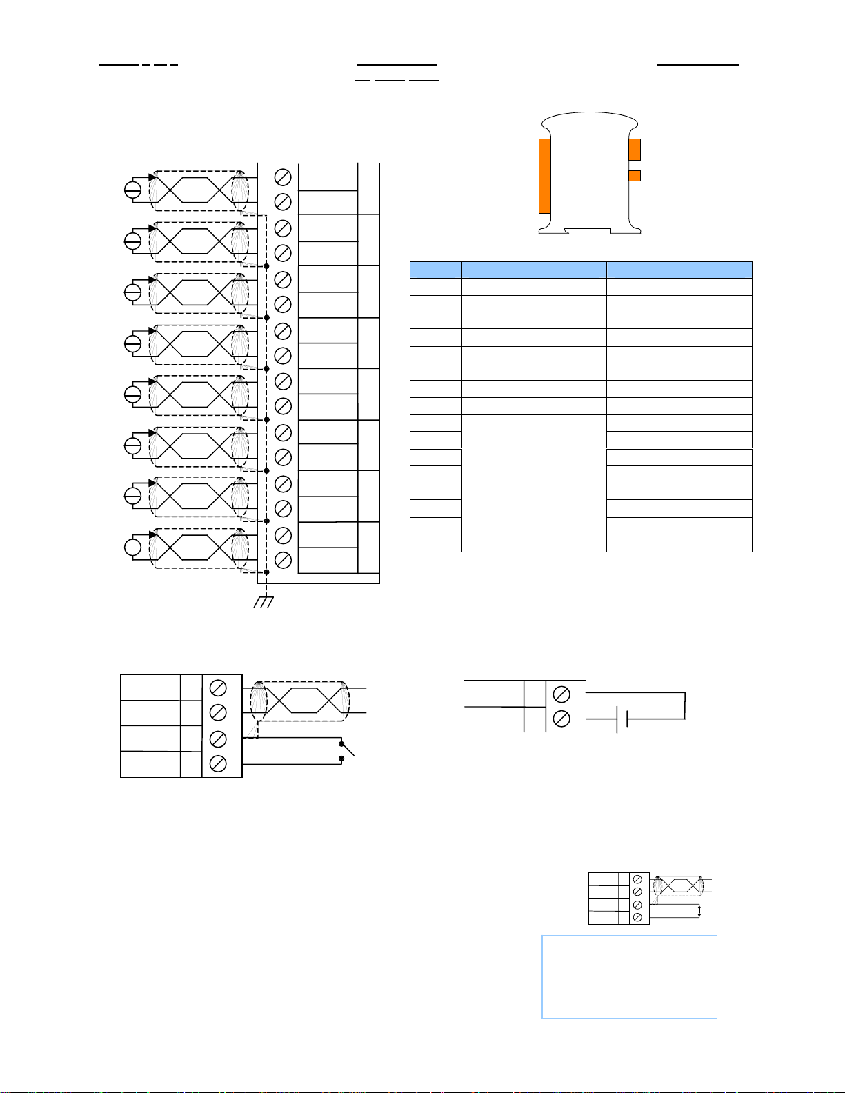
2 WIRING – I/O
+
V
-
+
V
-
+
V
-
+
V
-
+
V
-
+
V
-
+
V
-
+
V
-
1
2
3
4
5
6
7
8
9
10
11
12
13
14
15
16
V+
GNA
V+
GNA
V+
GNA
V+
GNA
V+
GNA
V+
GNA
V+
GNA
V+
GNA
IN
IN
IN
IN
IN
IN
IN
IN
I/O
0
1
2
3
4
5
6
7
Pin # ADC107 ADC207
1 INPUT 0+ INPUT 0+
2 ANALOG COMMON ANALOG COMMON
3 INPUT 1+ INPUT 1+
4 ANALOG COMMON ANALOG COMMON
5 INPUT 2+ INPUT 2+
6 ANALOG COMMON ANALOG COMMON
7 INPUT 3+ INPUT 3+
8 ANALOG COMMON ANALOG COMMON
9 INPUT 4+
10 ANALOG COMMON
11 INPUT 5+
12 ANALOG COMMON
13 INPUT 6+
14 ANALOG COMMON
Only Terminals 1
through 8 are
present on the
ADC107 model
15 INPUT 7+
16
RS-485
DC IN
ANALOG COMMON
WIRING – RS-485 WIRING – DC IN
DD+
GND
INIT
Notes:
Both ends of the RS-485 network should be terminated with a 100ohm, 1/4W, 1% resistor. Many OCS
controllers feature dip switches or jumpers which enable appropriate termination if the OCS is located on
a network end..
Init Default Setup:
1. Install jumper between INIT and GND terminals of the RS-485 port.
2. Apply power to Smartmod unit.
3. Read parameter words to see current parameters.
4. Write changes if necessary.
A
B
VV+
C
I
J
10-30Vdc
D
A
D-
B
D+
C
GND
D
INIT
Page 2 of 6
Page 3
MAN0837-03 ADC107/207 PAGE 3
The INIT Default RS485 Settings Are:
Modbus ID = 1
Baud rate = 9600
Parity = None
Stop Bits = 1
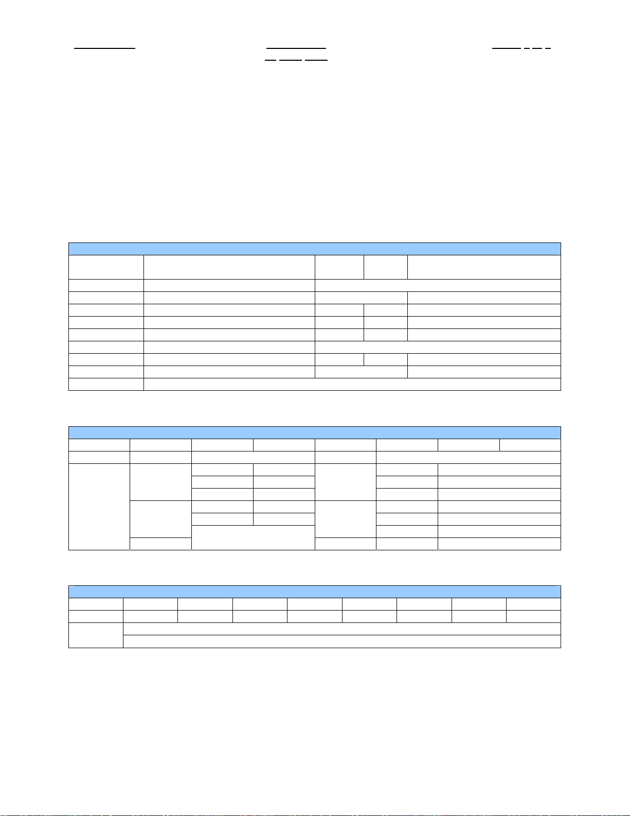
3 CONFIGURATION DATA
SmartMod Configuration settings are mapped into Modbus Register space. This configuration data may
be modified with any Modbus/RTU Master device. For convenience, Horner APG has developed a
variety of Cscape application files which allow an OCS (Xle, NX, LX, QX) to act as a SmartMod
configurator. Initial configuration of SmartMod module should be done on an individual basis, since all
modules come from the factory with a default Modbus ID of 1. Once each module on the network has its
own unique Modbus ID, further configuration adjustments can be made with the entire network powered.
All configuration parameters listed below (except 40012 Channel Enable) are stored in EPROM. That
means they should not be constantly rewritten.
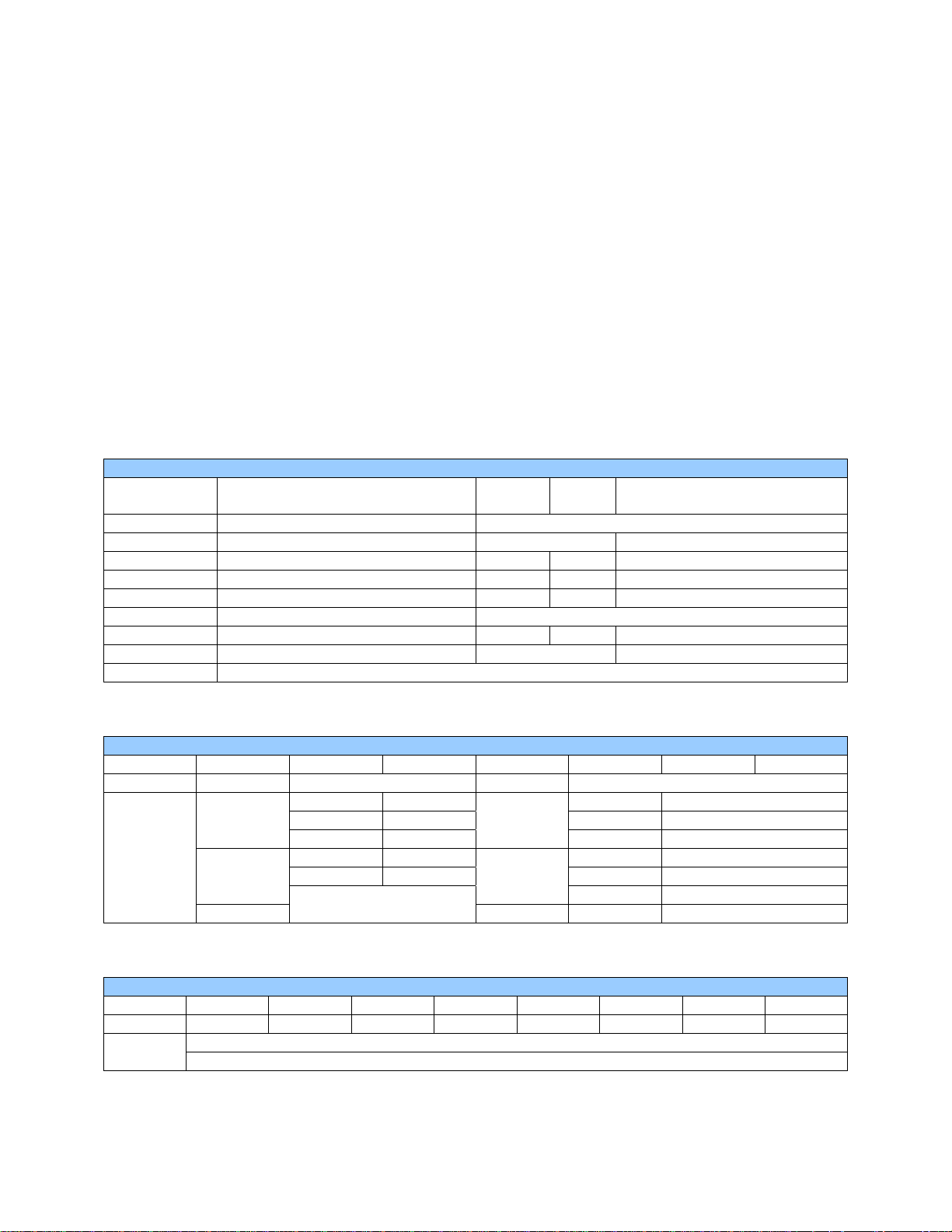
Configuration Parameters – Registers 40001 through 40013
Modbus
Register
40001-40005 Reserved
40006 Communications Parameters See Table 38.4kbaud, N, 8, 1, RTU Mode
40007 Modbus ID 1 255 1
40008 Rx/Tx Delay (in 2mS steps) 0 255 0mS
40009 Watchdog Timer (in 0.5s steps) 0 255 10 (5s)
40010 Modbus Coil Data Not Configuration Data – See I/O Data
40011 Input Type 4 4 4 (+/-10V)
40012 Channel Enable See Table 255 (Channels 1-8 enabled)
40013 Reserved
Register 40006 (Communications Parameters) Bit Definition
Bits 7-15 Bit 6 Bit 5 Bit 4 Bit 3 Bit 2 Bit 1 Bit 0
Unused Mode Parity Data Bits Baud Rate
0 = ASCII
Mode
1 = RTU
Mode
Bit 8-15 Bits 7 Bit 6 Bit 5 Bit 4 Bit 3 Bit 2 Bit 1 Bit 0
Unused Input 7 Input 6 Input 5 Input 4 Input 3 Input 2 Input 1 Input 0
Description
Value Meaning Value Meaning
0 Mark 0 1200 baud
1 Even
2 Odd 2 4800 baud
3 Space 3 9600 baud
Min
Max
Default
0 = 7 Data
Bits
1 2400 baud
1 = 8 Data
Bits
4 19200 baud
5-7 38400 baud
Register 40012 (Channel Enable) Bit Definition
0 = Disable Input
1 = Enable Input
Page 3 of 6
Page 4
PAGE 4 ADC107/207 MAN0837-03
t
4 INPUT / OUTPUT DATA
SmartMod Analog I/O utilizes both Modbus Registers (40001-40030) and Coils (1-11). It is possible to
access all data using Registers only, because the Coils can be accessed through Register 40010.
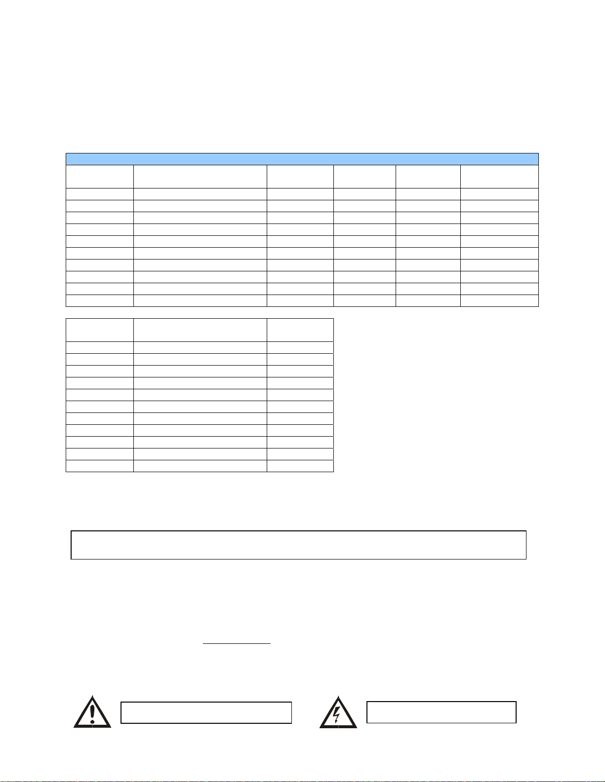
The following tables lists all Modbus I/O data available.
I/O Register Data (Registers 40014-40022)
Modbus
Register
Description
Access
Minimum Maximum
Units
40010 Mirror of Coil Data Read/Write n/a n/a n/a
40014 Cold Junction Temperature Read-only -1000 6000 0.01 degrees C
40015 Input 0 Read-only -10000 10000 1mV (0.001V)
40016 Input 1 Read-only -10000 10000 1mV (0.001V)
40017 Input 2 Read-only -10000 10000 1mV (0.001V)
40018 Input 3 Read-only -10000 10000 1mV (0.001V)
40019 Input 4 Read-only -10000 10000 1mV (0.001V)
40020 Input 5 Read-only -10000 10000 1mV (0.001V)
40021 Input 6 Read-only -10000 10000 1mV (0.001V)
40022 Input 7 Read-only -10000 10000 1mV (0.001V)
Modbus
Coil
00001 Open Detect Input 0 Read/Write
00002 Open Detect Input 1 Read/Write
00003 Open Detect Input 2 Read/Write
00004 Open Detect Input 3 Read/Write
00005 Open Detect Input 4 Read/Write
00006 Open Detect Input 5 Read/Write
00007 Open Detect Input 6 Read/Write
00008 Open Detect Input 7 Read/Write
00009 Watchdog Enabled Read/Write
00010 Watchdog Event Read/Write
00011 Power-up Event Read/Write
Description
Access
Watchdog Event & Power-up Event
Operation
If Coil 9 (Watchdog Enabled) is set,
Coil 10 (Watchdog Event) will set if the
Watchdog Timeout value is exceeded.
The Watchdog Timeout value is set in
Register 40009. When set, Coil 10
can be reset by the controller when
normal communications resumes.
The Power-up Event (Coil 11) is set
every time the power is applied. It can
be cleared by the controller if desired.
5 INSTALLATION / SAFETY
Warning: Remove power from the OCS controller, CAN port, and any peripheral equipmen
connected to this local system before adding or replacing this or any module.
a. All applicable codes and standards should be followed in the installation of this product.
b. Shielded, twisted-pair wiring should be used for best performance.
c. Shields may be terminated at the module terminal strip.
d. In severe applications, shields should be tied directly to the ground block within the panel.
e. Use the following wire type or equivalent: Belden 8441.
For detailed installation and a handy checklist
clearances, refer to the hardware manual of the controller you are using. (See the Additional
References section in this document.)
When found on the product, the following symbols specify:
Warning: Consult user documentation.
that covers panel box layout requirements and minimum
Warning: Electrical Shock Hazard.
Page 4 of 6
Page 5
MAN0837-03 ADC107/207 PAGE 5
6 TECHNICAL SUPPORT
For assistance and manual up-dates, contact Technical Support at the following locations:
Helpdesk: http://www.horner-apg.com/helpdesk
North America:
(317) 916-4274
www.heapg.com
Information in this document is subject to change without notice. This document is the property of Horner
APG and shall not be modified as to content unless specifically authorized.
Europe:
(+) 353-21-4321-266
www.horner-apg.com
Page 5 of 6
Page 6

PAGE 6 ADC107/207 MAN0837-03
NOTES
Page 6 of 6
Page 7
MAN0845-03 ADC120/220 PAGE 1 of 6
16
MAY 2007
20mA Analog Input Module
HE359ADC120 / HE359ADC220
SmartMod
16-Bit Resolution
1 SPECIFICATIONS
ADC120 ADC220 ADC120 ADC220
Number of
Channels
Input Ranges +/-20mA Terminal Type Screw Type, Removable
Resolution 16-Bit Storage Temp.
Input Impedance <50 Ohms
Linearity +/-0.1% Dimensions WxHxD
External Power
Supply Voltage
Required Power
(Steady State)
Required Power
(Inrush)
Isolation
4 8
10-30Vdc
30mA @ 24Vdc, typical
Negligible
2000Vac for 60 seconds
(Input/Power & Input/Serial)
Conversion Time
(PLC Update Rate)
Operating Temp.
Relative Humidity 5 to 90% Non-condensing
Weight 150g (6 oz.)
Communications
Default Comms.
Parameters
Supported Modbus
Commands
Determined by
Communications w/OCS
-40° to 85° Celsius
-10° to 60° Celsius
17.5mm x 100mm x 120mm
0.69” x 3.94” x 4.72”
Modbus/RTU (binary)
RS-485 half duplex
38400 baud, N, 8, 1, no h/s
Default Modbus ID 1
1,2,3,4,5,6,8,15,16
CE & UL Compliance See Compliance Table at http://www.heapg.com/Support/compliance.htm
Dimensions in inches are 0.69”W x 3.95”H x 4.72”D
Note: Number of I/O terminal connections vary from model to model
Information is subject to change without notice.
Page 8
PAGE 2 of 6 ADC120/220 MAN0845-03
16
MAY 2007
2 WIRING – I/O
+
+
+
+
+
+
+
+
1
2
3
4
5
6
7
8
9
10
11
12
13
14
15
16
I+
GNA
I+
GNA
I+
GNA
I+
GNA
I+
GNA
I+
GNA
I+
GNA
I+
GNA
IN
IN
IN
IN
IN
IN
IN
IN
0
1
Pin # ADC120 ADC220
1 INPUT 0+ INPUT 0+
2
2 ANALOG COMMON ANALOG COMMON
3 INPUT 1+ INPUT 1+
4 ANALOG COMMON ANALOG COMMON
3
5 INPUT 2+ INPUT 2+
6 ANALOG COMMON ANALOG COMMON
7 INPUT 3+ INPUT 3+
4
8 ANALOG COMMON ANALOG COMMON
9 INPUT 4+
10 ANALOG COMMON
5
11 INPUT 5+
12 ANALOG COMMON
13 INPUT 6+
6
14 ANALOG COMMON
15 INPUT 7+
16
7
I/O
Only Terminals 1
through 8 are
present on the
ADC120 model
RS-485
DC IN
ANALOG COMMON
WIRING – RS-485 WIRING – DC IN
DD+
GND
INIT
Notes:
Both ends of the RS-485 network should be terminated with a 100 Ohms, 1/4W, 1% resistor. Many OCS
controllers feature dip switches or jumpers which enable appropriate termination if the OCS is located on
a network end..
Init Default Setup:
1. Install jumper between INIT and GND terminals of the RS-485 port.
2. Apply power to Smartmod unit.
3. Read parameter words to see current parameters.
4. Write changes if necessary.
A
B
VV+
C
I
J
10-30Vdc
D
A
D-
B
D+
C
GND
D
INIT
The INIT Default RS485 Settings
Are:
Modbus ID = 1
Baud rate = 9600
Parity = None
Stop Bits = 1
Information is subject to change without notice.
Page 9
MAN0845-03 ADC120/220 PAGE 3 of 6
16
MAY 2007
3 CONFIGURATION DATA
SmartMod Configuration settings are mapped into Modbus Register space. This configuration data may
be modified with any Modbus/RTU Master device. For convenience, Horner APG has developed a
variety of Cscape application files which allow an OCS (Xle, NX, LX, QX) to act as a SmartMod
configurator. Initial configuration of SmartMod module should be done on an individual basis, since all
modules come from the factory with a default Modbus ID of 1. Once each module on the network has its
own unique Modbus ID, further configuration adjustments can be made with the entire network powered.
All configuration parameters listed below (except 40012 Channel Enable) are stored in EPROM. That
means they should not be constantly rewritten.
Configuration Parameters – Registers 40001 through 40013
Modbus
Register
40001-40005 Reserved
40006 Communications Parameters See Table 38.4kbaud, N, 8, 1, RTU Mode
40007 Modbus ID 1 255 1
40008 Rx/Tx Delay (in 2mS steps) 0 255 0mS
40009 Watchdog Timer (in 0.5s steps) 0 255 10 (5s)
40010 Modbus Coil Data Not Configuration Data – See I/O Data
40011 Input Type 6 6 6 (+/-20mA)
40012 Channel Enable See Table 255 (Channels 1-8 enabled)
40013 Reserved
Register 40006 (Communications Parameters) Bit Definition
Bits 7-15 Bit 6 Bit 5 Bit 4 Bit 3 Bit 2 Bit 1 Bit 0
Unused Mode Parity Data Bits Baud Rate
0 = ASCII
Mode
1 = RTU
Mode
Bit 8-15 Bits 7 Bit 6 Bit 5 Bit 4 Bit 3 Bit 2 Bit 1 Bit 0
Unused Input 7 Input 6 Input 5 Input 4 Input 3 Input 2 Input 1 Input 0
Description
Value Meaning Value Meaning
0 Mark 0 1200 baud
1 Even
2 Odd 2 4800 baud
3 Space 3 9600 baud
Min
Max
Default
0 = 7 Data
Bits
1 2400 baud
1 = 8 Data
Bits
4 19200 baud
5-7 38400 baud
Register 40012 (Channel Enable) Bit Definition
0 = Disable Input
1 = Enable Input
Information is subject to change without notice.
Page 10
PAGE 4 of 6 ADC120/220 MAN0845-03
16
MAY 2007
4 INPUT / OUTPUT DATA
SmartMod Analog I/O utilizes both Modbus Registers (40001-40030) and Coils (1-11). It is possible to
access all data using Registers only, because the Coils can be accessed through Register 40010.
The following tables lists all Modbus I/O data available.
I/O Register Data (Registers 40014-40022)
Modbus
Register
40010 Mirror of Coil Data Read/Write n/a n/a n/a
40014 Cold Junction Temperature Read-only -1000 6000 0.01 degrees C
40015 Input 0 Read-only -20000 +20000 1µA (0.001mA)
40016 Input 1 Read-only -20000 +20000 1µA (0.001mA)
40017 Input 2 Read-only -20000 +20000 1µA (0.001mA)
40018 Input 3 Read-only -20000 +20000 1µA (0.001mA)
40019 Input 4 Read-only -20000 +20000 1µA (0.001mA)
40020 Input 5 Read-only -20000 +20000 1µA (0.001mA)
40021 Input 6 Read-only -20000 +20000 1µA (0.001mA)
40022 Input 7 Read-only -20000 +20000 1µA (0.001mA)
Modbus
Coil
00001 Open Detect Input 0 Read/Write
00002 Open Detect Input 1 Read/Write
00003 Open Detect Input 2 Read/Write
00004 Open Detect Input 3 Read/Write
00005 Open Detect Input 4 Read/Write
00006 Open Detect Input 5 Read/Write
00007 Open Detect Input 6 Read/Write
00008 Open Detect Input 7 Read/Write
00009 Watchdog Enabled Read/Write
00010 Watchdog Event Read/Write
00011 Power-up Event Read/Write
Description
Description
Access
Access
Minimum Maximum
Watchdog Event & Power-up Event
Operation
Units
If Coil 9 (Watchdog Enabled) is set,
Coil 10 (Watchdog Event) will set if the
Watchdog Timeout value is exceeded.
The Watchdog Timeout value is set in
Register 40009. When set, Coil 10
can be reset by the controller when
normal communications resumes.
The Power-up Event (Coil 11) is set
every time the power is applied. It can
be cleared by the controller if desired.
Information is subject to change without notice.
Page 11
MAN0845-03 ADC120/220 PAGE 5 of 6
t
16
MAY 2007
5 INSTALLATION / SAFETY
Warning: Remove power from the OCS controller, CAN port, and any peripheral equipmen
connected to this local system before adding or replacing this or any module.
a. All applicable codes and standards should be followed in the installation of this product.
b. Shielded, twisted-pair wiring should be used for best performance.
c. Shields may be terminated at the module terminal strip.
d. In severe applications, shields should be tied directly to the ground block within the panel.
e. Use the following wire type or equivalent: Belden 8441.
For detailed installation and a handy checklist
clearances, refer to the hardware manual of the controller being used. (See the Additional References
section in this document.)
When found on the product, the following symbols specify:
Warning: Consult user documentation.
that covers panel box layout requirements and minimum
Warning: Electrical Shock Hazard.
6 TECHNICAL SUPPORT
For assistance and manual up-dates, contact Technical Support at the following locations:
Helpdesk: http://www.horner-apg.com/helpdesk
North America:
(317) 916-4274
www.heapg.com
Europe:
(+) 353-21-4321-266
www.horner-apg.com
Information is subject to change without notice.
Page 12

PAGE 6 of 6 ADC120/220 MAN0845-03
16
MAY 2007
NOTES
Information is subject to change without notice.
Page 13
MAN0838-03 DAC007/107 PAGE 1 of 6
Analog Output Module
HE359DAC007 / HE359DAC107
Selectable 0-20mA or 0-10V
SmartMod
1 µA or 1 mV Resolution
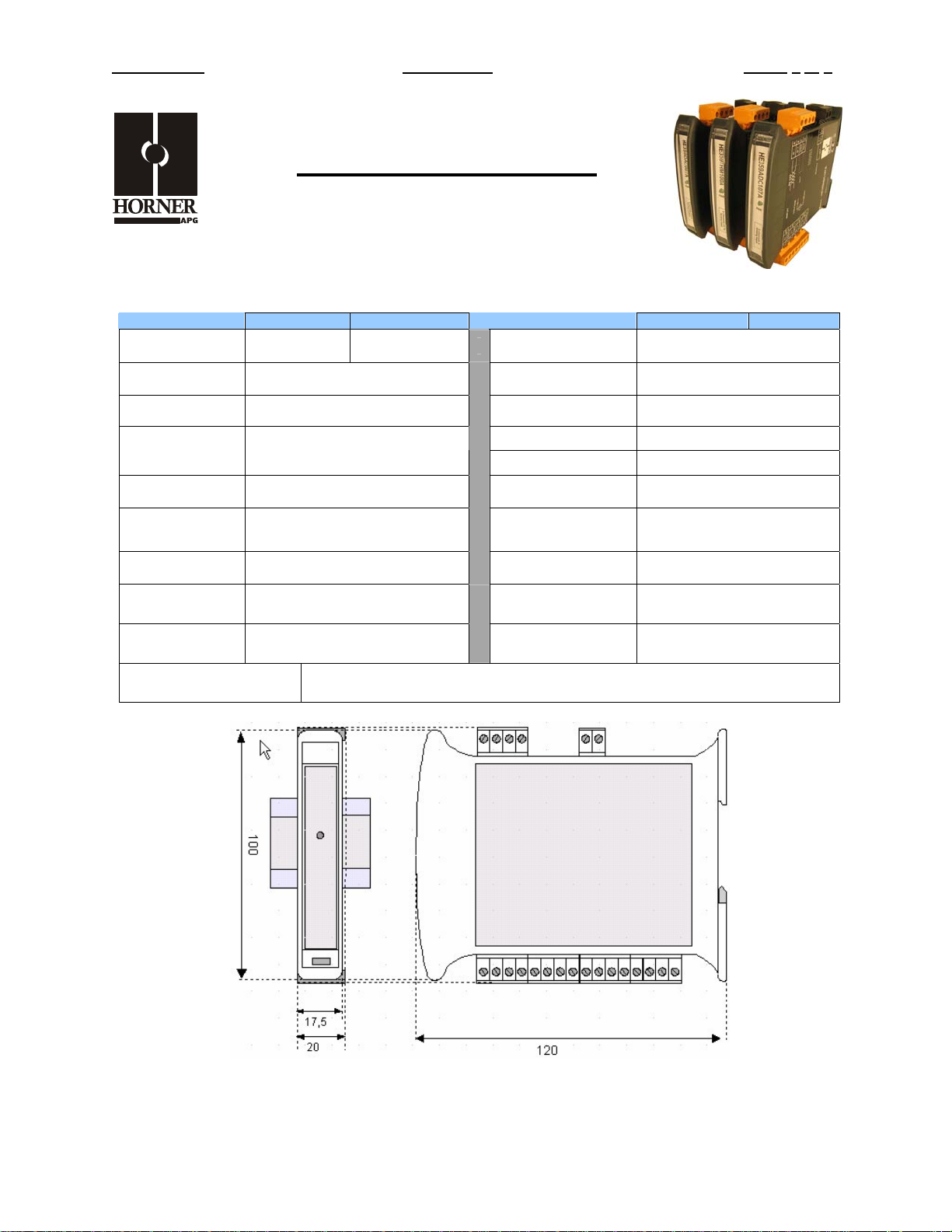
1 SPECIFICATIONS
DAC007 DAC107 DAC007 DAC107
Number of
Channels
Output Ranges
Resolution 1 µA or 1 mV Storage Temp.
Load Resistance
Output
Calibration
External Power
Supply Voltage
Required Power
(Steady State)
Required Power
(Inrush)
Isolation
2 4
0-20mA or 0-10V
Voltage: >5Kohm
Current: <500ohm
Voltage: +/-10mV
Current: +/-20uA
18-30Vdc
30mA @ 24Vdc, typical
(100mA max)
Negligible
2000Vac for 60 seconds
(Input/Power & Input/Comms)
Auxiliar y Voltage 12V @ 20mA (4 channels)
Terminal Type Screw Type, Removable
Operating Temp.
Relative Humidity 5 to 95% Non-condensing
Dimensions WxHxD
Weight 150g (6 oz.)
Communications
Default Comms.
Parameters
Supported Modbus
Commands (family)
-40° to 85° Celsius
-10° to 60° Celsius
17.5mm x 100mm x 120mm
0.69” x 3.94” x 4.72”
Modbus/RTU (binary)
RS-485 half duplex
38400 baud, N, 8, 1, no h/s
Default Modbus ID 1
1,2,3,4,5,6,8,15,16
CE & UL Compliance See Compliance Table at http://www.heapg.com/Support/compliance.htm
Dimensions in inches are 0.69”W x 3.95”H x 4.72”D
Note: Number of I/O terminal connections vary from model to model
Information is subject to change without notice.
Page 14
PAGE 2 of 6 DAC007/107 MAN0838-03
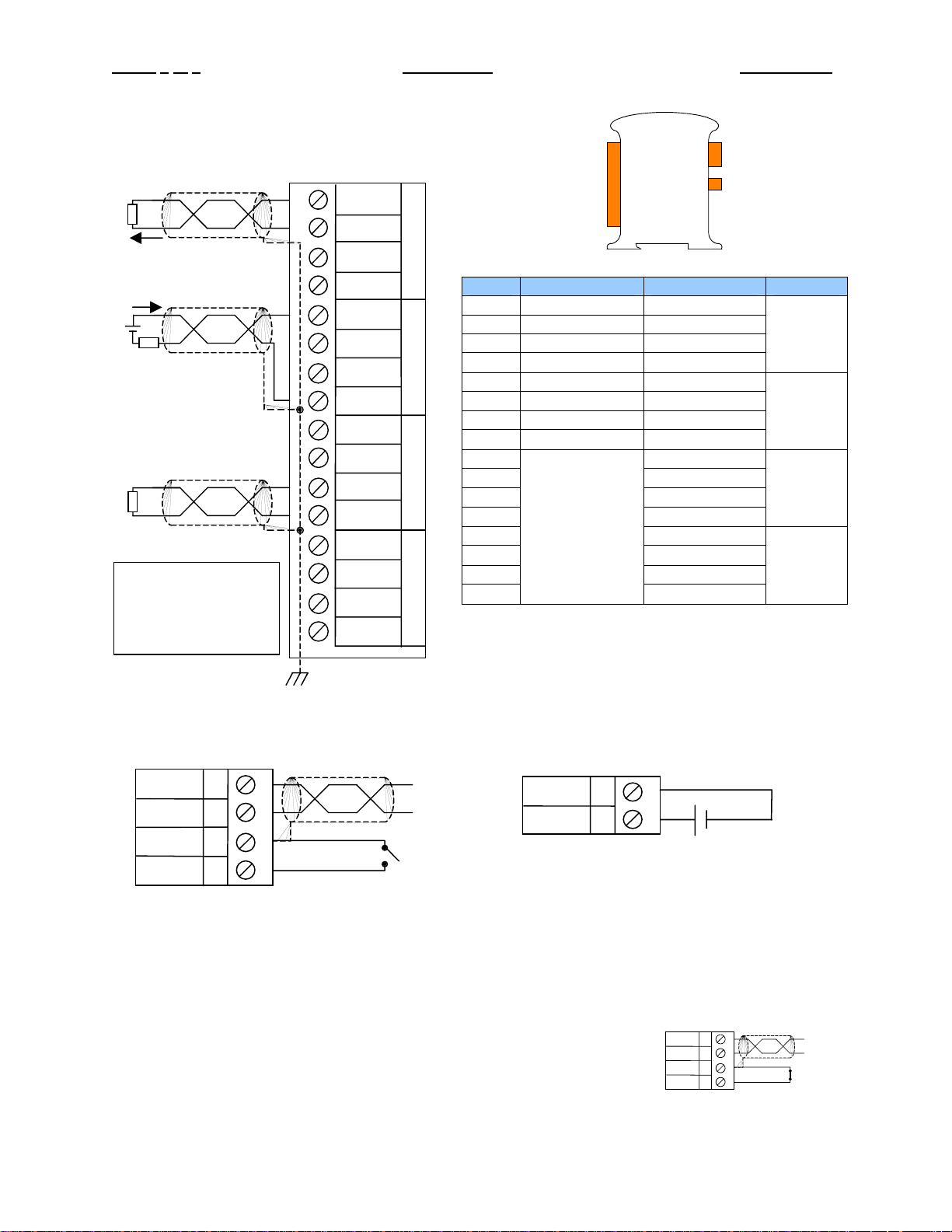
2 WIRING – I/O
ACTIVE
LOOP
PASSIVE
LOOP
+
VOLTAGE
NOTE: EACH
CHAN N EL MAY BE
INDEPENDENTLY
WIRED
1
2
3
4
5
6
7
8
9
10
11
12
13
14
15
16
I
AUX
V
GNA
I
AUX
V
GNA
I
AUX
V
GNA
I
AUX
V
GNA
IN
0
IN
1
IN
2
IN
3
I/O
Pin # DAC007 DAC107
1 I I
2 AUX AUX
3 V V
4 GNA GNA
5 I I
6 AUX AUX
7 V V
8 GNA GNA
9 I
10 AUX
11 V
12 GNA
13 I
14 AUX
15 V
16
Only Terminals
1 through 8 are
present on the
DAC007 model
RS-485
DC IN
OUT 0
OUT 1
OUT 2
OUT 3
GNA
WIRING – RS-485 WIRING – DC IN
Notes:
Both ends of the RS-485 network should be terminated with a 100ohm, 1/4W, 1% resistor. Many OCS
controllers feature dip switches or jumpers which enable appropriate termination if the OCS is located on
a network end..
Init Default Setup:
1. Install jumper between INIT and GND terminals of the RS-485 port.
2. Apply power to Smartmod unit.
3. Read parameter words to see current parameters.
4. Write changes if necessary.
DD+
GND
INIT
A
B
C
D
VV+
I
J
10-30Vdc
18-30 VDC
A
D-
B
D+
C
GND
D
INIT
Information is subject to change without notice.
Page 15
MAN0838-03 DAC007/107 PAGE 3 of 6
The INIT Default RS485 Settings Are:
Modbus ID = 1
Baud rate = 9600
Parity = None
Stop Bits = 1
3 CONFIGURATION DATA
SmartMod Configuration settings are mapped into Modbus Register space. This configuration data may
be modified with any Modbus/RTU Master device. For convenience, Horner APG has developed a
variety of Cscape application files which allow an OCS (Xle, NX, LX, QX) to act as a SmartMod
configurator. Initial configuration of SmartMod module should be done on an individual basis, since all
modules come from the factory with a default Modbus ID of 1. Once each module on the network has its
own unique Modbus ID, further configuration adjustments can be made with the entire network powered.
All configuration parameters listed below (except 40012 Channel Enable) are stored in EPROM. That
means they should not be constantly rewritten.
Configuration Parameters – Registers 40001 through 40013
Modbus
Register
40001-40005 Reserved
40006 Communications Parameters See Table 38.4kbaud, N, 8, 1, RTU Mode
40007 Modbus ID 1 255 1
40008 Rx/Tx Delay (in 2mS steps) 0 255 0mS
40009 Watchdog Timer (in 0.5s steps) 0 255 10 (5s)
40010 Modbus Coil Data Not Configuration Data – See I/O Data
40011 Reserved
40012 Reserved
40013 Reserved
40014 Output Type See Table 0 (All Channels Current)
Register 40006 (Communications Parameters) Bit Definition
Bits 7-15 Bit 6 Bit 5 Bit 4 Bit 3 Bit 2 Bit 1 Bit 0
Unused Mode Parity Data Bits Baud Rate
0 = ASCII
Mode
1 = RTU
Mode
Bit 4-15 Bit 3 Bit 2 Bit 1 Bit 0
Unused
Description
Value Meaning Value Meaning
0 Mark 0 1200 baud
1 Even
2 Odd 2 4800 baud
3 Space 3 9600 baud
Register 40014 (Output Type) Bit Definition
Min
0 = 7 Data
Bits
1 = 8 Data
Bits
5-7 38400 baud
Output 3 Output 2 Output 1 Output 0
Max
1 2400 baud
4 19200 baud
0 = Current (0-20mA)
1 = Voltage (0-10V)
Default
Information is subject to change without notice.
Page 16
PAGE 4 of 6 DAC007/107 MAN0838-03
4 INPUT / OUTPUT DATA
SmartMod Analog I/O utilizes both Modbus Registers (40001-40030) and Coils (1-11). It is possible to
access all data using Registers only, because the Coils can be accessed through Register 40010.
The following tables lists all Modbus I/O data available.
I/O Register Data (Registers 40010-40026)
Modbus
Register
Description
Access
Minimum Maximum
Units
40010 Mirror of Coil Data Read/Write n/a n/a n/a
40015 Output 0 Read/Write 0 20000 1uA or 1mV
40016 Output 1 Read/Write 0 20000 1uA or 1mV
40017 Output 2 Read/Write 0 20000 1uA or 1mV
40018 Output 3 Read/Write 0 20000 1uA or 1mV
40019-40022 Reserved
40023 Default/Safe Value Out 0 Read/Write 0 20000 1uA or 1mV
40024 Default/Safe Value Out 1 Read/Write 0 20000 1uA or 1mV
40025 Default/Safe Value Out 2 Read/Write 0 20000 1uA or 1mV
40026 Default/Safe Value Out 3 Read/Write 0 20000 1uA or 1mV
Modbus
Coil
00009 Watchdog Enabled Read/Write
00010 Watchdog Event Read/Write
00011 Power-up Event Read/Write
Modbus
Register
40010 bit 0 Watchdog Enabled Read/Write
40010 bit 1 Watchdog Event Read/Write
40010 bit 2 Power-up Event Read/Write
Description
Access
Watchdog Event & Power-up Event
If Coil 9 (Watchdog Enabled) is set,
Coil 10 (Watchdog Event) will set if the
Watchdog Timeout value is exceeded.
The Watchdog Timeout value is set in
Register 40009. When set, Coil 10
can be reset by the controller when
Description Access
normal communications resumes.
The Power-up Event (Coil 11) is set
every time the power is applied. It can
be cleared by the controller if desired.
Operation
5 INSTALLATION / SAFETY
Warning: Remove power from the OCS controller, CAN port, and any peripheral equipment
connected to this local system before adding or replacing this or any module.
a. All applicable codes and standards should be followed in the installation of this product.
b. Shielded, twisted-pair wiring should be used for best performance.
c. Shields may be terminated at the module terminal strip.
d. In severe applications, shields should be tied directly to the ground block within the panel.
e. Use the following wire type or equivalent: Belden 8441.
For detailed installation and a handy checklist
clearances, refer to the hardware manual of the controller you are using. (See the Additional
References section in this document.)
When found on the product, the following symbols specify:
Warning: Consult user documentation.
that covers panel box layout requirements and minimum
Warning: Electrical Shock Hazard.
Information is subject to change without notice.
Page 17

MAN0838-03 DAC007/107 PAGE 5 of 6
6 TECHNICAL SUPPORT
For assistance and manual up-dates, contact Technical Support at the following locations:
Helpdesk: http://www.horner-apg.com/helpdesk
North America:
(317) 916-4274
www.heapg.com
Europe:
(+) 353-21-4321-266
www.horner-apg.com
Information is subject to change without notice.
Page 18

PAGE 6 of 6 DAC007/107 MAN0838-03
NOTES
Information is subject to change without notice.
Page 19
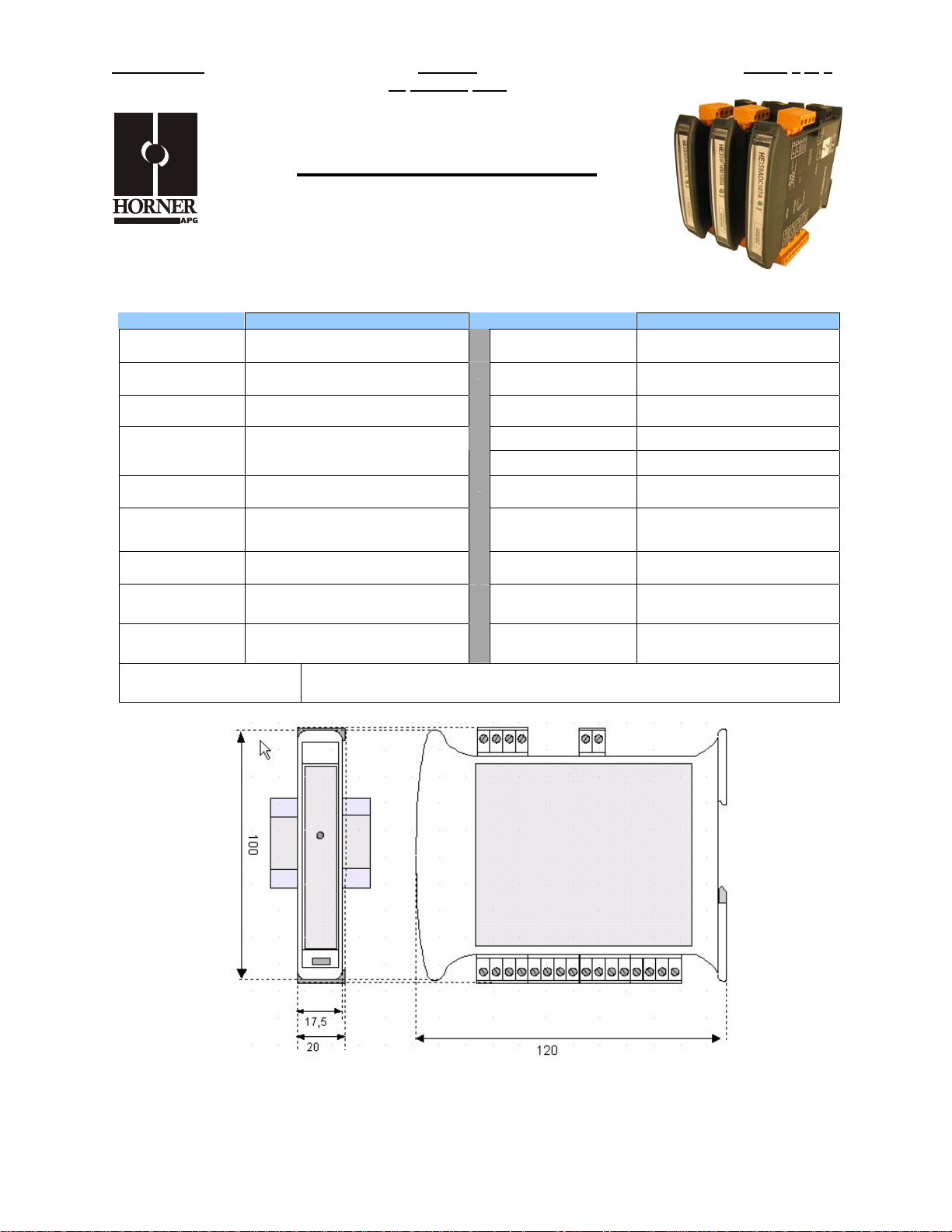
MAN0839-02 DAC201 PAGE 1 of 6
15
MARCH 2007
Analog Output Module
SmartMod
HE359DAC201
0-10V
14-Bit Resolution
1 SPECIFICATIONS
DAC201 DAC201
Number of
Channels
Output Ranges
Resolution
Load Resistance Voltage: >5Kohm
Output
Calibration
External Power
Supply Voltage
Required Power
(Steady State)
Required Power
(Inrush)
Isolation
Approximately 14-Bit
Voltage: +/-10mV
30mA @ 24Vdc, typical
2000Vac for 60 seconds
(Input/Power & Input/Comms)
8
0-10V
18-30Vdc
Negligible
Thermal Drift
Terminal Type Screw Type, Removable
Storage Temp.
Operating Temp.
Relative Humidity 5 to 95% Non-condensing
Dimensions WxHxD
Weight 150g (6 oz.)
Communications
Default Comms.
Parameters
Supported Modbus
Commands (family)
100ppm max
-40° to 85° Celsius
-10° to 60° Celsius
17.5mm x 100mm x 120mm
0.69” x 3.94” x 4.72”
Modbus/RTU (binary)
RS-485 half duplex
38400 baud, N, 8, 1, no h/s
Default Modbus ID 1
1,2,3,4,5,6,8,15,16
CE & UL Compliance See Compliance Table at http://www.heapg.com/Support/compliance.htm
Dimensions in inches are 0.69”W x 3.95”H x 4.72”D
Note: Number of I/O terminal connections vary from model to model
Information is subject to change without notice.
Page 20
PAGE 2 of 6 DAC201 MAN0839-02
15
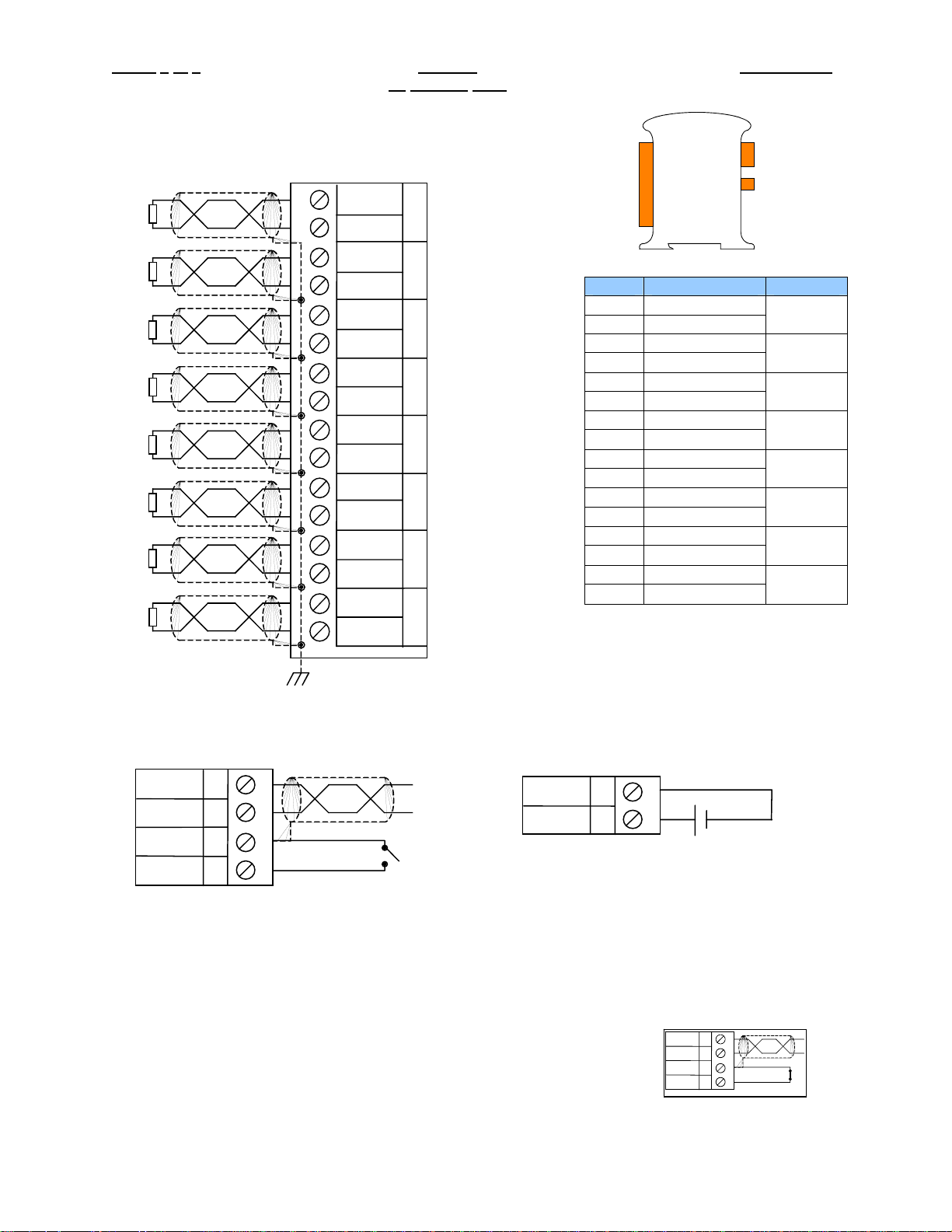
2 WIRING – I/O
+
V
-
+
V
-
+
1
2
3
4
5
V
-
+
6
7
V
-
+
8
9
V
-
+
10
11
V
-
+
12
13
V
-
+
V
-
14
15
16
MARCH 2007
V
Q
GNA
V
Q
GNA
V
Q
GNA
V
Q
GNA
V
Q
GNA
V
Q
GNA
V
Q
GNA
V
Q
GNA
RS-485
I/O
DC IN
0
1
2
3
4
5
6
Pin # DAC201
1 V
2 GNA
3 V
4 GNA
5 V
6 GNA
7 V
8 GNA
9 V
10 GNA
11 V
12 GNA
13 V
14 GNA
15 V
16 GNA
OUT 0
OUT 1
OUT 2
OUT 3
OUT 4
OUT 5
OUT 6
OUT 7
7
WIRING – RS-485 WIRING – DC IN
Notes:
Both ends of the RS-485 network should be terminated with a 100ohm, 1/4W, 1% resistor. Many OCS
controllers feature dip switches or jumpers which enable appropriate termination if the OCS is located on
a network end..
Init Default Setup:
1. Install jumper between INIT and GND terminals of the RS-485 port.
2. Apply power to Smartmod unit.
3. Read parameter words to see current parameters.
4. Write changes if necessary.
DD+
GND
INIT
A
B
C
D
VV+
I
J
10-30Vdc
A
D-
B
D+
C
GND
D
INIT
Information is subject to change without notice.
Page 21
MAN0839-02 DAC201 PAGE 3 of 6
15
MARCH 2007
The INIT Default RS485 Settings Are:
Modbus ID = 1
Baud rate = 9600
Parity = None
Stop Bits = 1
3 CONFIGURATION DATA
SmartMod Configuration settings are mapped into Modbus Register space. This configuration data may
be modified with any Modbus/RTU Master device. For convenience, Horner APG has developed a
variety of Cscape application files which allow an OCS (Xle, NX, LX, QX) to act as a SmartMod
configurator. Initial configuration of SmartMod module should be done on an individual basis, since all
modules come from the factory with a default Modbus ID of 1. Once each module on the network has its
own unique Modbus ID, further configuration adjustments can be made with the entire network powered.
All configuration parameters listed below (except 40012 Channel Enable) are stored in EPROM. That
means they should not be constantly rewritten.
Configuration Parameters – Registers 40001 through 40013
Modbus
Register
40001-40005 Reserved
40006 Communications Parameters See Table 38.4kbaud, N, 8, 1, RTU Mode
40007 Modbus ID 1 255 1
40008 Rx/Tx Delay (in 2mS steps) 0 255 0mS
40009 Watchdog Timer (in 0.5s steps) 0 255 10 (5s)
40010 Modbus Coil Data Not Configuration Data – See I/O Data
40011 Reserved
40012 Reserved
40013 Reserved
40014 Output Type 255 255 255 (All channels Voltage)
Register 40006 (Communications Parameters) Bit Definition
Bits 7-15 Bit 6 Bit 5 Bit 4 Bit 3 Bit 2 Bit 1 Bit 0
Unused Mode Parity Data Bits Baud Rate
0 = ASCII
Mode
1 = RTU
Mode
Description
Value Meaning Value Meaning
0 Mark 0 1200 baud
1 Even
2 Odd 2 4800 baud
3 Space 3 9600 baud
Min
Max
Default
0 = 7 Data
Bits
1 2400 baud
1 = 8 Data
Bits
4 19200 baud
5-7 38400 baud
Information is subject to change without notice.
Page 22
PAGE 4 of 6 DAC201 MAN0839-02
t
15
MARCH 2007
4 INPUT / OUTPUT DATA
SmartMod Analog I/O utilizes both Modbus Registers (40001-40030) and Coils (1-11). It is possible to
access all data using Registers only, because the Coils can be accessed through Register 40010.
The following tables lists all Modbus I/O data available.
I/O Register Data (Registers 40010-40026)
Modbus
Register
40010 Mirror of Coil Data Read/Write n/a n/a n/a
40015 Output 0 Read/Write 0 10000 1mV
40016 Output 2 Read/Write 0 10000 1mV
40017 Output 4 Read/Write 0 10000 1mV
40018 Output 6 Read/Write 0 10000 1mV
40019 Output 1 Read/Write 0 10000 1mV
40020 Output 3 Read/Write 0 10000 1mV
40021 Output 5 Read/Write 0 10000 1mV
40022 Output 7 Read/Write 0 10000 1mV
40023 Default/Safe Value Out 0 Read/Write 0 10000 1mV
40024 Default/Safe Value Out 1 Read/Write 0 10000 1mV
40025 Default/Safe Value Out 2 Read/Write 0 10000 1mV
40026 Default/Safe Value Out 3 Read/Write 0 10000 1mV
40027 Default/Safe Value Out 4 Read/Write 0 10000 1mV
40028 Default/Safe Value Out 5 Read/Write 0 10000 1mV
40029 Default/Safe Value Out 6 Read/Write 0 10000 1mV
40030 Default/Safe Value Out 7 Read/Write 0 10000 1mV
Modbus
Coil
00009 Watchdog Enabled Read/Write
00010 Watchdog Event Read/Write
00011 Power-up Event Read/Write
Modbus
Register
40010 bit 0 Watchdog Enabled Read/Write
40010 bit 1 Watchdog Event Read/Write
40010 bit 2 Power-up Event Read/Write
Description
Description
Description Access
Access
Access
Minimum Maximum
Watchdog Event & Power-up Event
If Coil 9 (Watchdog Enabled) is set,
Coil 10 (Watchdog Event) will set if the
Watchdog Timeout value is exceeded.
The Watchdog Timeout value is set in
Register 40009. When set, Coil 10
can be reset by the controller when
normal communications resumes.
The Power-up Event (Coil 11) is set
every time the power is applied. It can
be cleared by the controller if desired.
Units
Operation
5 INSTALLATION / SAFETY
Warning: Remove power from the OCS controller, CAN port, and any peripheral equipmen
connected to this local system before adding or replacing this or any module.
a. All applicable codes and standards should be followed in the installation of this product.
b. Shielded, twisted-pair wiring should be used for best performance.
c. Shields may be terminated at the module terminal strip.
d. In severe applications, shields should be tied directly to the ground block within the panel.
e. Use the following wire type or equivalent: Belden 8441.
Information is subject to change without notice.
Page 23

MAN0839-02 DAC201 PAGE 5 of 6
15
For detailed installation and a handy checklist that covers panel box layout requirements and minimum
clearances, refer to the hardware manual of the controller you are using. (See the Additional
References section in this document.)
When found on the product, the following symbols specify:
Warning: Consult user documentation.
MARCH 2007
Warning: Electrical Shock Hazard.
6 TECHNICAL SUPPORT
Helpdesk: http://www.horner-apg.com/helpdesk
For assistance and manual up-dates, contact Technical Support at the following locations:
North America:
(317) 916-4274
www.heapg.com
Europe:
(+) 353-21-4321-266
www.horner-apg.com
Information is subject to change without notice.
Page 24

PAGE 6 of 6 DAC201 MAN0839-02
15
MARCH 2007
NOTES
Information is subject to change without notice.
Page 25
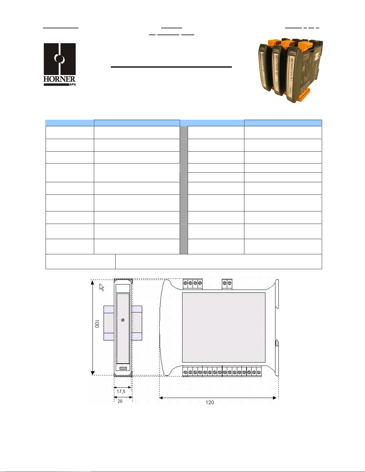
MAN0842-02 DIM610 PAGE 1 of 6
15
MARCH 2007
DC Digital Input Module
SmartMod
HE359DIM610
12/24VDC Negative Logic
1 SPECIFICATIONS
DIM610 DIM610
Number of
Channels
Input Ranges
OFF Point 0-3VDC Storage Temp.
ON Point 10-30VDC
Input Impedence 4.7Kohm Dimensions WxHxD
External Power
Supply Voltage
Required Power
(Steady State)
Required Power
(Inrush)
Isolation
35mA @ 24Vdc, typical
2000Vac for 60 seconds
(Input/Power & Input/Comms)
12
12/24 VDC
10-30Vdc
Negligible
PLC Update Rate
Terminal Type Screw Type, Removable
Operating Temp.
Relative Humidity 5 to 95% Non-condensing
Weight 150g (6 oz.)
Communications
Default Comms.
Parameters
Supported Modbus
Commands
Determined by
Communications w/OCS
-40° to 85° Celsius
-10° to 60° Celsius
17.5mm x 100mm x 120mm
0.69” x 3.94” x 4.72”
Modbus/RTU (binary)
RS-485 half duplex
38400 baud, N, 8, 1, no h/s
Default Modbus ID 1
1,2,3,4,5,6,8,15,16
CE & UL Compliance See Compliance Table at http://www.heapg.com/Support/compliance.htm
Dimensions in inches are 0.69”W x 3.95”H x 4.72”D
Note: Number of I/O terminal connections vary from model to model
Information is subject to change without notice.
Page 26
PAGE 2 of 6 DIM610 MAN0842-02
15
MARCH 2007
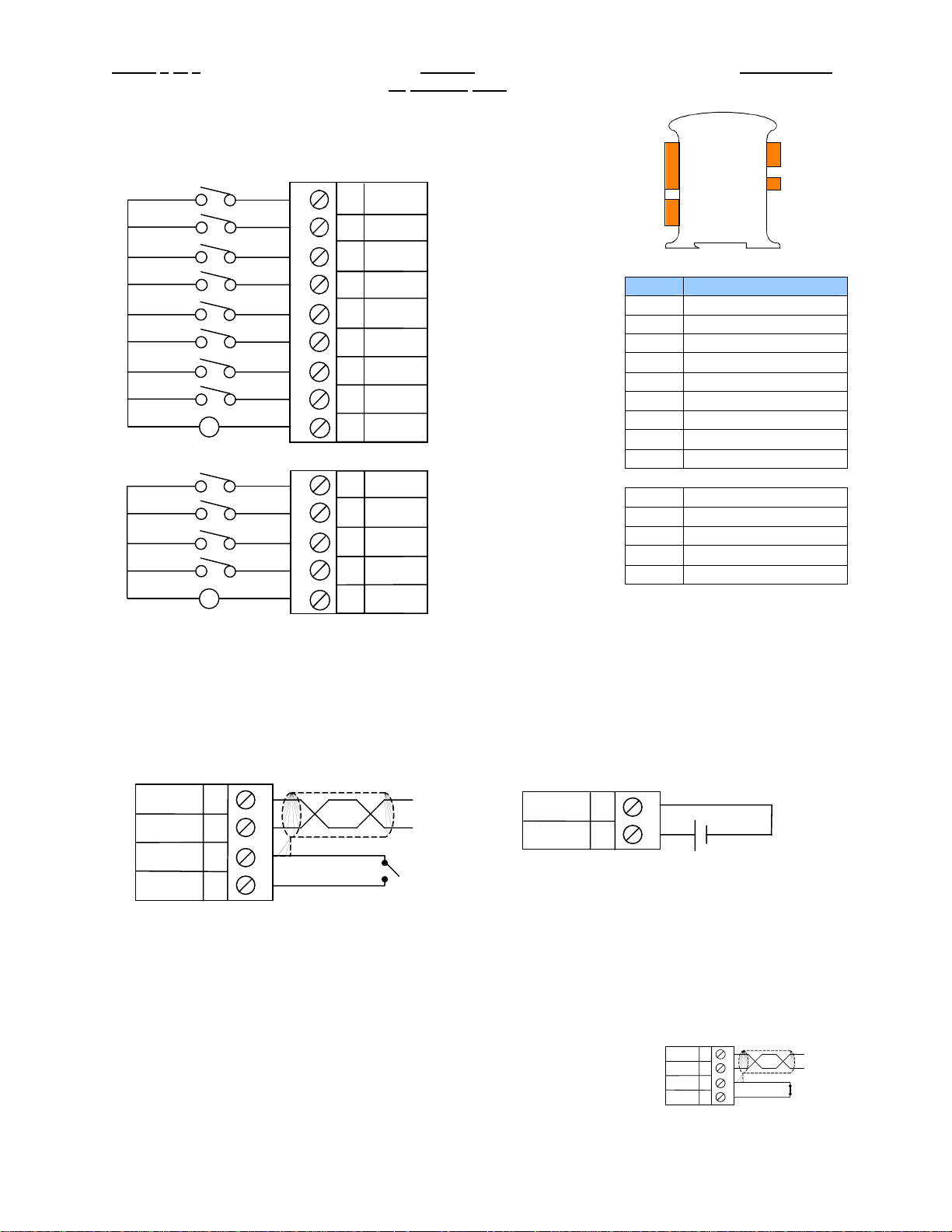
2 WIRING – I/O
-
+
1
2
3
4
5
6
7
8
9
IN 0
IN 1
IN 2
IN 3
IN 4
IN 5
IN 6
IN 7
COM
12/24VDC
11
IN 8
12
IN 9
13
IN 10
14
-
+
12/24VDC
15
IN 11
COM
I/O
Pin # DIM610
1 INPUT 0
2 INPUT 1
3 INPUT 2
4 INPUT 3
5 INPUT 4
6 INPUT 5
7 INPUT 6
8 INPUT 7
9 INPUT COMMON 1
11 INPUT 8
12 INPUT 9
13 INPUT 10
14 INPUT 11
15 INPUT COMMON 2
INPUTS 0-7 & 8-11 are
isolated from each other
RS-485
DC IN
WIRING – RS-485 WIRING – DC IN
Notes:
Both ends of the RS-485 network should be terminated with a 100ohm, 1/4W, 1% resistor. Many OCS
controllers feature dip switches or jumpers which enable appropriate termination if the OCS is located on
a network end..
Init Default Setup:
1. Install jumper between INIT and GND terminals of the RS-485 port.
2. Apply power to Smartmod unit.
3. Read parameter words to see current parameters.
4. Write changes if necessary.
DD+
GND
INIT
A
B
C
D
VV+
I
J
10-30Vdc
A
D-
B
D+
C
GND
INIT
D
Information is subject to change without notice.
Page 27
MAN0842-02 DIM610 PAGE 3 of 6
15
The INIT Default RS485 Settings Are:
Modbus ID = 1
Baud rate = 9600
Parity = None
Stop Bits = 1
MARCH 2007
3 CONFIGURATION DATA
SmartMod Configuration settings are mapped into Modbus Register space. This configuration data may
be modified with any Modbus/RTU Master device. For convenience, Horner APG has developed a
variety of Cscape application files which allow an OCS (Xle, NX, LX, QX) to act as a SmartMod
configurator. Initial configuration of SmartMod module should be done on an individual basis, since all
modules come from the factory with a default Modbus ID of 1. Once each module on the network has its
own unique Modbus ID, further configuration adjustments can be made with the entire network powered.
All configuration parameters listed below are stored in EPROM. That means they should not be
constantly rewritten.
Configuration Parameters – Registers 40001 through 40014
Modbus
Register
40001-40005 Reserved
40006 Communications Parameters See Table 38.4kbaud, N, 8, 1, RTU Mode
40007 Modbus ID 1 255 1
40008 Rx/Tx Delay (2mS steps) 0 255 0mS
40009 Watchdog Timer (0.5s steps) 0 255 10 (5s)
40010 Watchdog Data I/O Watchdog Data – See Table Below
40011 Input Data I/O Data – See Table Below
40012-40014 Reserved
Register 40006 (Communications Parameters) Bit Definition
Bits 7-15 Bit 6 Bit 5 Bit 4 Bit 3 Bit 2 Bit 1 Bit 0
Unused Mode Parity Data Bits Baud Rate
0 = ASCII
Mode
Bit 11-15 Bit 10 Bit 9 Bit 8 Bit 0-7
Unused
Bit
15
IN 7 IN 6 IN 5 IN 4 IN 3 IN 2 IN 1 IN 0 reserved IN 11 IN 10 IN 9 IN 8
Bit
14
1 = RTU
Mode
Bit
13
Register 40010 (Watchdog Coils Mirror) Bit Definition
Power-up Event Watchdog Event Watchdog Enable
1 = Event Ocurred 1 = Event Ocurred 1 = Enabled
Bit
12
Description
Value Meaning Value Meaning
0 Mark 0 1200 baud
1 Even
2 Odd 2 4800 baud
3 Space 3 9600 baud
0 = No Event 0 = No Event 0 = Not Enabled
Register 40011 (Input Coil Mirror) Bit Definition
Bit
11
Bit
Bit 9 Bit 8 Bit 4-7 Bit 3 Bit 2 Bit 1 Bit 0
10
Min
0 = 7 Data
Bits
1 = 8 Data
Bits
5-7 38400 baud
Max
1 2400 baud
4 19200 baud
Default
Unused
Information is subject to change without notice.
Page 28
PAGE 4 of 6 DIM610 MAN0842-02
15
MARCH 2007
4 INPUT / OUTPUT DATA
SmartMod Digital I/O utilizes both Modbus Registers (40001-40014) and Coils (1-28). It is possible to
access all data using Registers only, because the Coils can be accessed through Register 40 010-40011.
The following tables lists all Modbus I/O data available.
I/O Register Data (Registers 40014-40022)
Modbus
Register
40010 Mirror of Watchdog Coils Read/Write See Chart in Section 3 (Register 40010)
40011 Mirror of Digital Input Coils Read-only See Chart in Section 3 (Register 40011)
40012-40014 Reserved
Modbus
Coil
00001 Watchdog Enabled Read/Write
00002 Watchdog Event Read/Write
00003 Power-up Event Read/Write
00017 Digital Input 0 Read-only
00018 Digital Input 1 Read-only
00019 Digital Input 2 Read-only
00020 Digital Input 3 Read-only
00021 Digital Input 4 Read-only
00022 Digital Input 5 Read-only
00023 Digital Input 6 Read-only
00024 Digital Input 7 Read-only
00025 Digital Input 8 Read-only
00026 Digital Input 9 Read-only
00027 Digital Input 10 Read-only
00028 Digital Input 11 Read-only
Description
Description
Access
Access
Notes
Watchdog Event & Power-up Event
Operation
If Coil 1 (Watchdog Enabled) is set,
Coil 2 (Watchdog Event) will set if the
Watchdog Timeout value is exceeded.
The Watchdog Timeout value is set in
Register 40009. When set, Coil 2 can
be reset by the controller when normal
communications resumes.
The Power-up Event (Coil 3) is set
every time the power is applied. It can
be cleared by the controller if desired.
Information is subject to change without notice.
Page 29
MAN0842-02 DIM610 PAGE 5 of 6
t
15
MARCH 2007
5 INSTALLATION / SAFETY
Warning: Remove power from the OCS controller, CAN port, and any peripheral equipmen
connected to this local system before adding or replacing this or any module.
a. All applicable codes and standards should be followed in the installation of this product.
b. Shielded, twisted-pair wiring should be used for best performance.
c. Shields may be terminated at the module terminal strip.
d. In severe applications, shields should be tied directly to the ground block within the panel.
e. Use the following wire type or equivalent: Belden 8441.
For detailed installation and a handy checklist
clearances, refer to the hardware manual of the controller you are using. (See the Additional
References section in this document.)
When found on the product, the following symbols specify:
Warning: Consult user documentation.
that covers panel box layout requirements and minimum
Warning: Electrical Shock Hazard.
6 TECHNICAL SUPPORT
For assistance and manual up-dates, contact Technical Support at the following locations:
Helpdesk: http://www.horner-apg.com/helpdesk
North America:
(317) 916-4274
www.heapg.com
Europe:
(+) 353-21-4321-266
www.horner-apg.com
Information is subject to change without notice.
Page 30

PAGE 6 of 6 DIM610 MAN0842-02
15
MARCH 2007
NOTES
Information is subject to change without notice.
Page 31
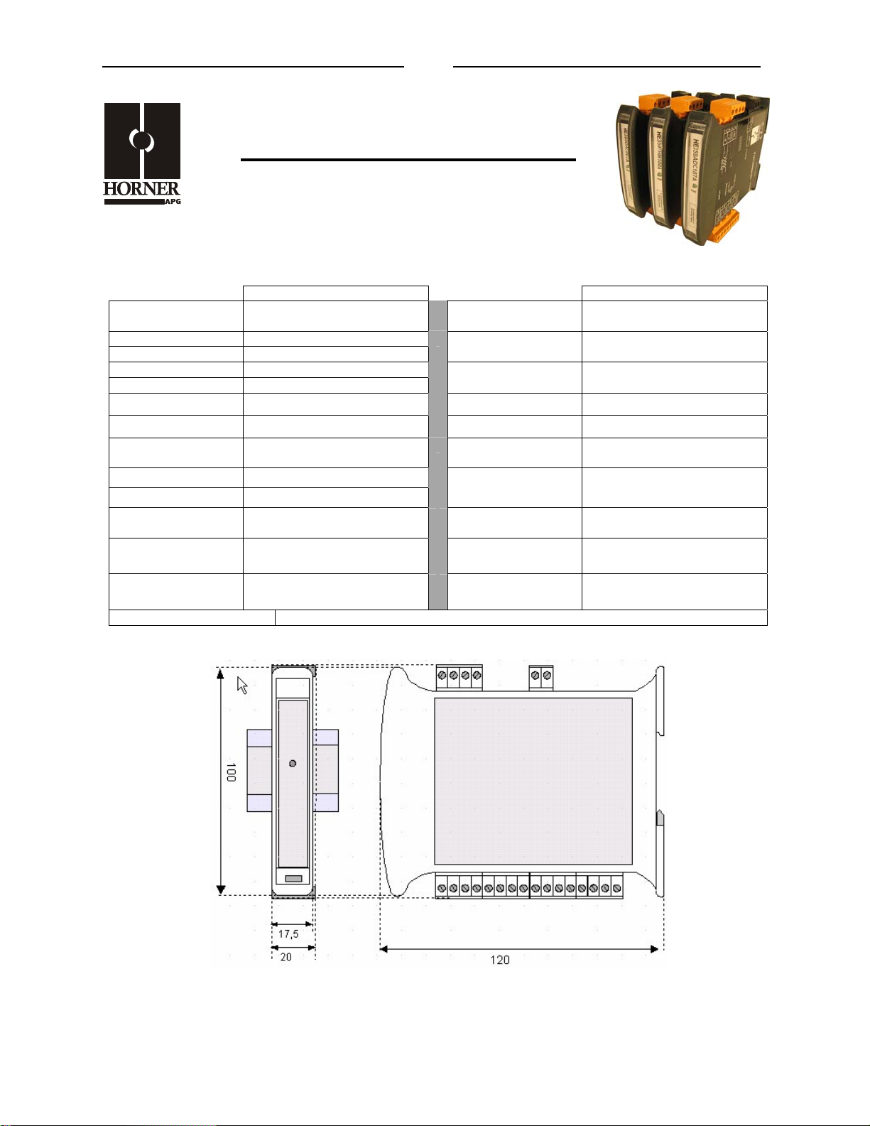
MAN0844-03 DIQ512 PAGE 1 of 6
Digital Input/Output Module
Four 12/24V DC Inputs (neg. logic)
Four Relay Outputs (2A, max)
SmartMod
HE359DIQ512
1 SPECIFICATIONS
DIQ512 DIQ512
Inputs per Module
(Commons)
Input Voltage Range 12/24 VDC
Impedence 4.7k ohms
Peak Voltage 30 VDC
ON voltage level 10 VDC
OFF voltage level 0-3 VDC Operating Temp.
Outputs per Module 4 (2 SPDT, 2 SPST)
Max Switching
Power
Minimum Load 5 VDC, 10mA
Maximum Voltage 250VAC, 110 VDC
Required Power
(Steady State)
Required Power
(Inrush)
Isolation
CE & UL Compliance See Compliance Table at http://www.heapg.com/Support/compliance.htm
(Input/Power & Input/Comms)
4 (1 Common)
2A @ 250 VAC
2A @ 30 VDC
45mA @ 24Vdc, typical
Negligible
2000Vac for 60 seconds
Dimensions in inches are 0.69”W x 3.95”H x 4.72”D
Note: Number of I/O terminal connections vary from model to model
Sample Time (PLC
Update Rate)
Terminal Type Screw Type, Removable
Storage Temp.
Relative Humidity 5 to 95% Non-condensing
Dimensions WxHxD
Weight 210g (8.4 oz.)
Communications
Default Comms.
Parameters
Supported Modbus
Commands
Min. 20mS - Determined by
Communications w/OCS
-40° to 85° Celsius
-10° to 60° Celsius
17.5mm x 100mm x 120mm
0.69” x 3.94” x 4.72”
Modbus/RTU (binary)
RS-485 half duplex
38400 baud, N, 8, 1, no h/s
Default Modbus ID 1
1,2,3,4,5,6,8,15,16
Information is subject to change without notice.
Page 32
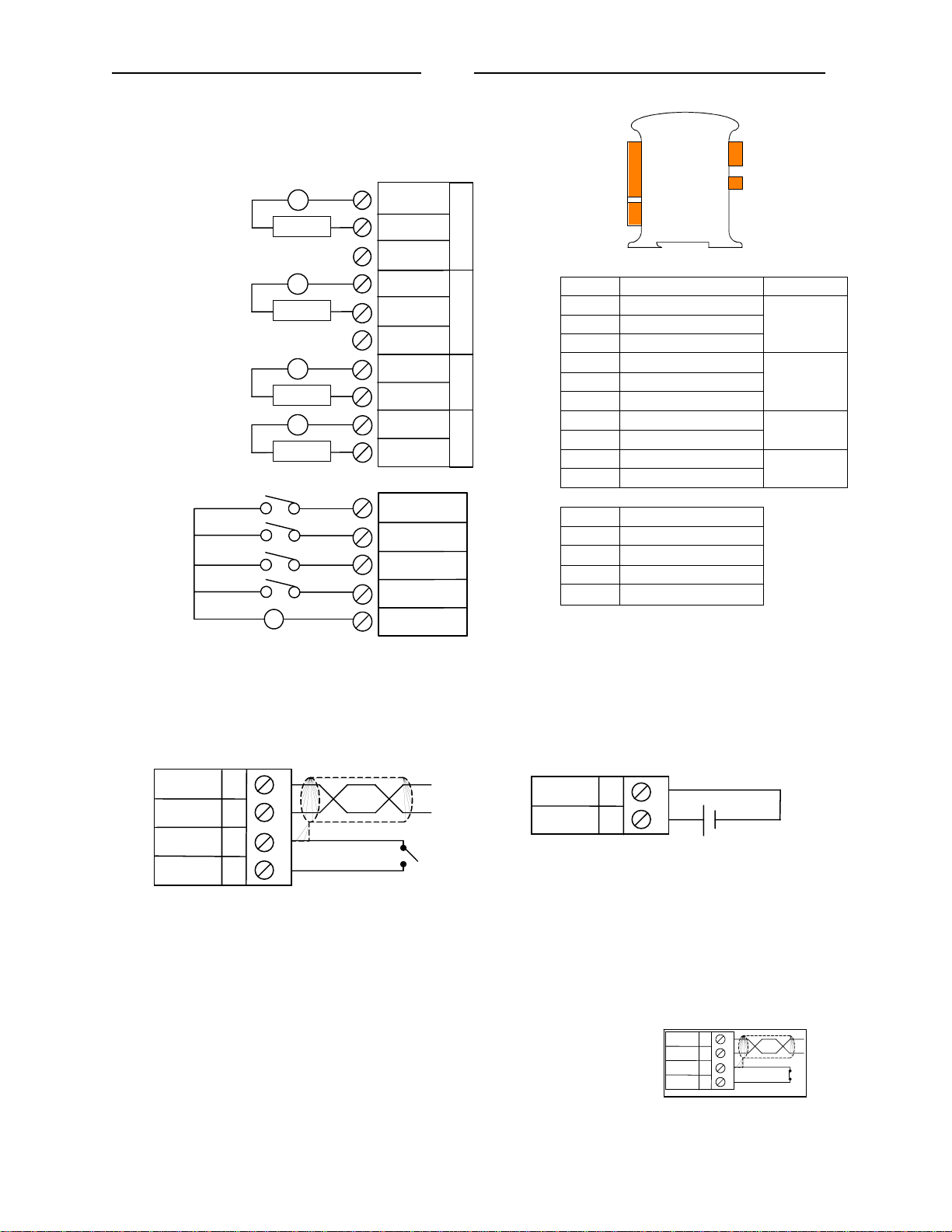
PAGE 2 of 6 DIQ512 MAN0844-03
2 WIRING – I/O
5-250Vac
5-30Vdc
or
5-250Vac
or
5-30Vdc
5-250Vac
or
5-30Vdc
5-250Vac
or
5-30Vdc
N
L
-
+
LOAD
N
L
-
+
LOAD
N
L
-
+
LOAD
N
L
-
+
LOAD
1
2
3
4
5
6
7
8
9
10
COM
NO
NC
COM
NO
NC
COM
NO
COM
NO
OUT 0
OUT 1
OUT 2 OUT 3
I/O
Pin # DIQ512
1 COM
2 N. O.
3 N. C.
4 COM
5 N. O.
6 N. C.
7 COM
8 N.O.
9 COM
10 N.O.
IN 0
12
13
IN 1
12 INPUT 0
13 INPUT 1
14 INPUT 2
IN 2
14
IN 3
-
+
12/24Vdc
15
16
COM
15 INPUT 3
16 COM
RS-485
DC IN
OUT 0
OUT 1
OUT 2
OUT 3
Note:
Each
Output
COM
isolated
WIRING – RS-485 WIRING – DC IN
DD+
GND
INIT
Notes:
Both ends of the RS-485 network should be terminated with a 100ohm, 1/4W, 1% resistor. Many OCS
controllers feature dip switches or jumpers which enable appropriate termination if the OCS is located on
a network end.
Init Default Setup:
1. Install jumper between INIT and GND terminals of the RS-485 port.
2. Apply power to Smartmod unit.
3. Read parameter words to see current parameters.
4. Write changes if necessary.
A
B
VV+
C
I
J
10-30Vdc
D
A
D-
B
D+
C
GND
D
INIT
Information is subject to change without notice.
Page 33
MAN0844-03 DIQ512 PAGE 3 of 6
The INIT Default RS485 Settings Are:
Modbus ID = 1
Baud rate = 9600
Parity = None
Stop Bits = 1
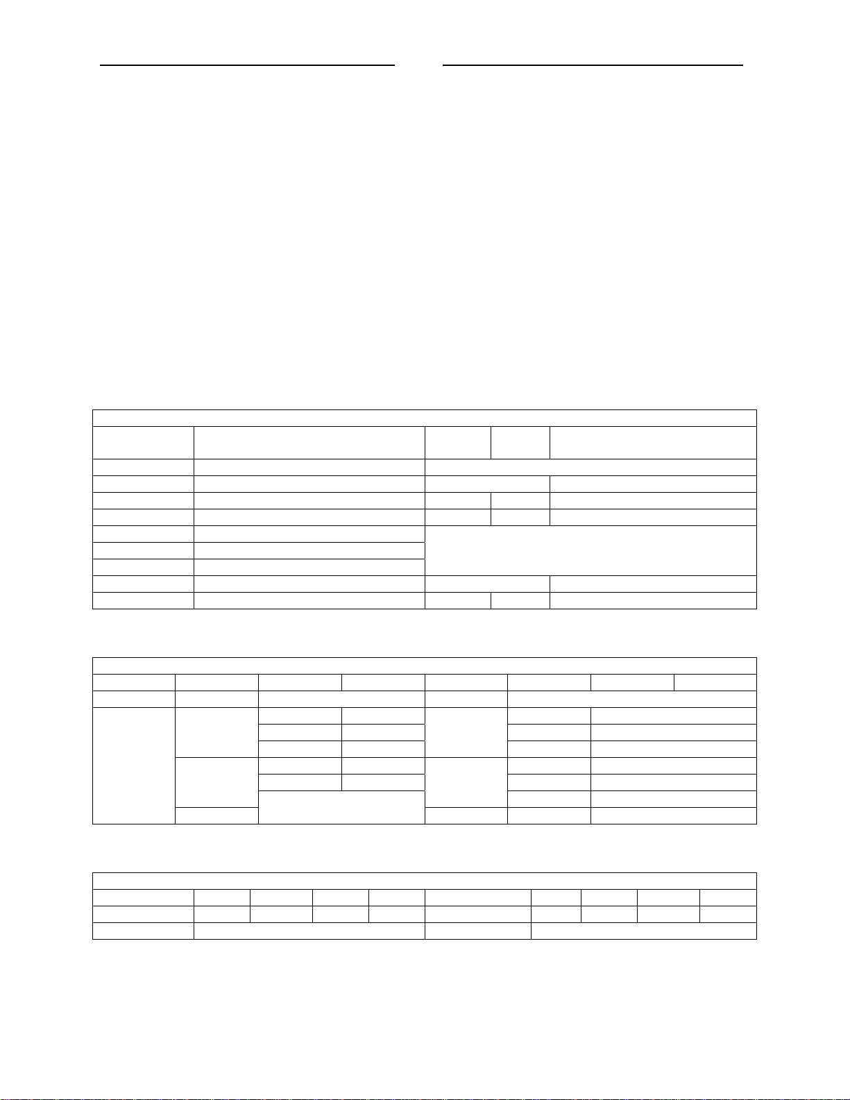
3 CONFIGURATION DATA
SmartMod Configuration settings are mapped into Modbus Register space. This configuration data may
be modified with any Modbus/RTU Master device. For convenience, Horner APG has developed a
variety of Cscape application files which allow an OCS (XLe, NX, LX, QX) to act as a SmartMod
configurator. Initial configuration of SmartMod module should be done on an individual basis, since all
modules come from the factory with a default Modbus ID of 1. Once each module on the network has its
own unique Modbus ID, further configuration adjustments can be made with the entire network powered.
All configuration parameters are stored in EPROM. That means they should not be constantly rewritten.
Configuration Parameters – Registers 40001 through 40013
Modbus
Register
40001-40005 Reserved
40006 Communications Parameters See Table 38.4kbaud, N, 8, 1, RTU Mode
40007 Modbus ID 1 255 1
40008 Rx/Tx Delay (in 2mS steps) 0 255 0mS
40009 Input Coils
40010 Output Coils
40011 Coils
40012 Power Up/Safe See Table 0
40013 Watchdog Timer (in 0.5s steps) 0 255 10 (5s)
Register 40006 (Communications Parameters) Bit Definition
Bits 7-15 Bit 6 Bit 5 Bit 4 Bit 3 Bit 2 Bit 1 Bit 0
Unused Mode Parity Data Bits Baud Rate
0 = ASCII
Mode
Bits 12-15 Bit 11 Bit 10 Bit 9 Bit 8 Bit 4-7 Bit 3 Bit 2 Bit 1 Bit 0
Unused Out 3 Out 2 Out 1 Out 0 Unused Out 3 Out 2 Out 1 Out 0
PowerUp Value Safe Value
1 = RTU
Mode
Description
Value Meaning Value Meaning
0 Mark 0 1200 baud
1 Even
2 Odd 2 4800 baud
3 Space 3 9600 baud
Register 40012 (Power Up / Safe) Bit Definition
Min
Not Configuration Data – See I/O Data
0 = 7 Data
Bits
1 = 8 Data
Bits
5-7 38400 baud
Max
1 2400 baud
4 19200 baud
Default
Information is subject to change without notice.
Page 34
PAGE 4 of 6 DIQ512 MAN0844-03
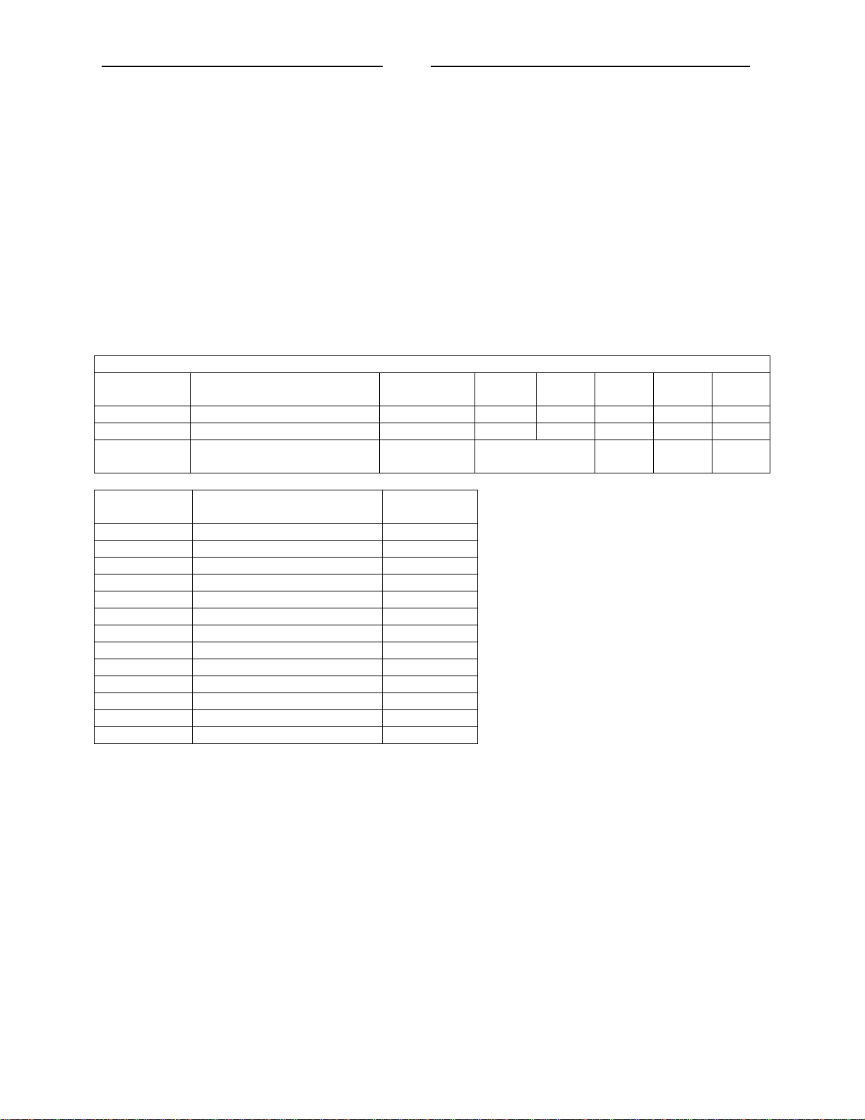
4 INPUT / OUTPUT DATA
SmartMod Digital I/O data utilizes both Modbus Registers (40009-40011) and Coils (1-35). It is possible
to access all data using Registers only, because the Coils data can be accessed through Registers.
The following tables lists all Modbus I/O data available.
I/O Register Data (Registers 40009-40011)
Modbus
Register
40009 Mirror of Input Coil Data Read-only unused In 3 In 2 In 1 In 0
40010 Mirror of Output Data Read/Write unused Out 3 Out 2 Out 1 Out 0
40011 Mirror of WatchDog Data Read/Write unused
Modbus
Coil
00001 Input 0 Read-only
00002 Input 1 Read-only
00003 Input 2 Read-only
00004 Input 3 Read-only
0005-00016 Reserved
00017 Output 0 Read/Write
00018 Output 1 Read/Write
00019 Output 2 Read/Write
00020 Output 3 Read/Write
00021-00032 Reserved
00033 Watchdog Enabled Read/Write
00034 Watchdog Event Read/Write
00035 Power-up Event Read/Write
Description
Description
Access
*W.D. = Watchdog
Access
Bits 4-
15
Watchdog Event & Power-up Event
Bit 12 Bit 11 Bit 10 Bit 9
PwrUp
Event
Operation
If Coil 33 (Watchdog Enabled) is set,
Coil 34 (Watchdog Event) will set if the
Watchdog Timeout value is exceeded.
The Watchdog Timeout value is set in
Register 40013. When set, Coil 34
can be reset by the controller when
normal communications resumes.
The Power-up Event (Coil 35) is set
every time the power is applied. It can
be cleared by the controller if desired.
W.D.*
Event
W.D.*
Enbld
Information is subject to change without notice.
Page 35
MAN0844-03 DIQ512 PAGE 5 of 6
t
5 INSTALLATION / SAFETY
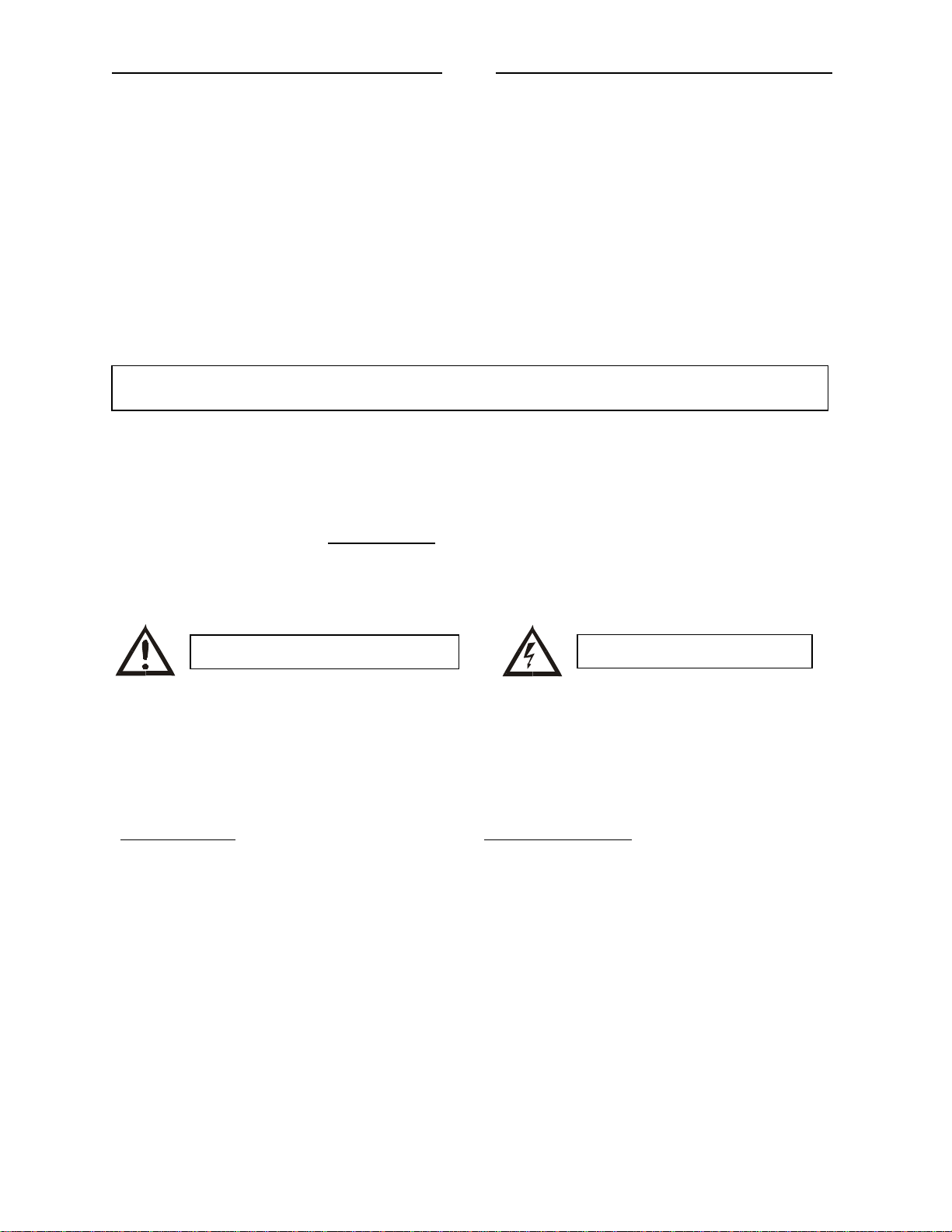
Warning: Remove power from the OCS controller, CAN port, and any peripheral equipmen
connected to this local system before adding or replacing this or any module.
a. All applicable codes and standards should be followed in the installation of this product.
b. Shielded, twisted-pair wiring should be used for best performance.
c. Shields may be terminated at the module terminal strip.
d. In severe applications, shields should be tied directly to the ground block within the panel.
e. Use the following wire type or equivalent: Belden 8441.
For detailed installation and a
clearances, refer to the hardware manual of the controller you are using. (See the Additional
References section in this document.)
When found on the product, the following symbols specify:
Warning: Consult user documentation.
handy checklist that covers panel box layout requirements and minimum
Warning: Electrical Shock Hazard.
6 TECHNICAL SUPPORT
For assistance and manual up-dates, contact Technical Support at the following locations:
North America:
(317) 916-4274
www.heapg.com
Europe:
(+) 353-21-4321-266
www.horner-apg.com
Information is subject to change without notice.
Page 36

PAGE 6 of 6 DIQ512 MAN0844-03
NOTES
Information is subject to change without notice.
Page 37
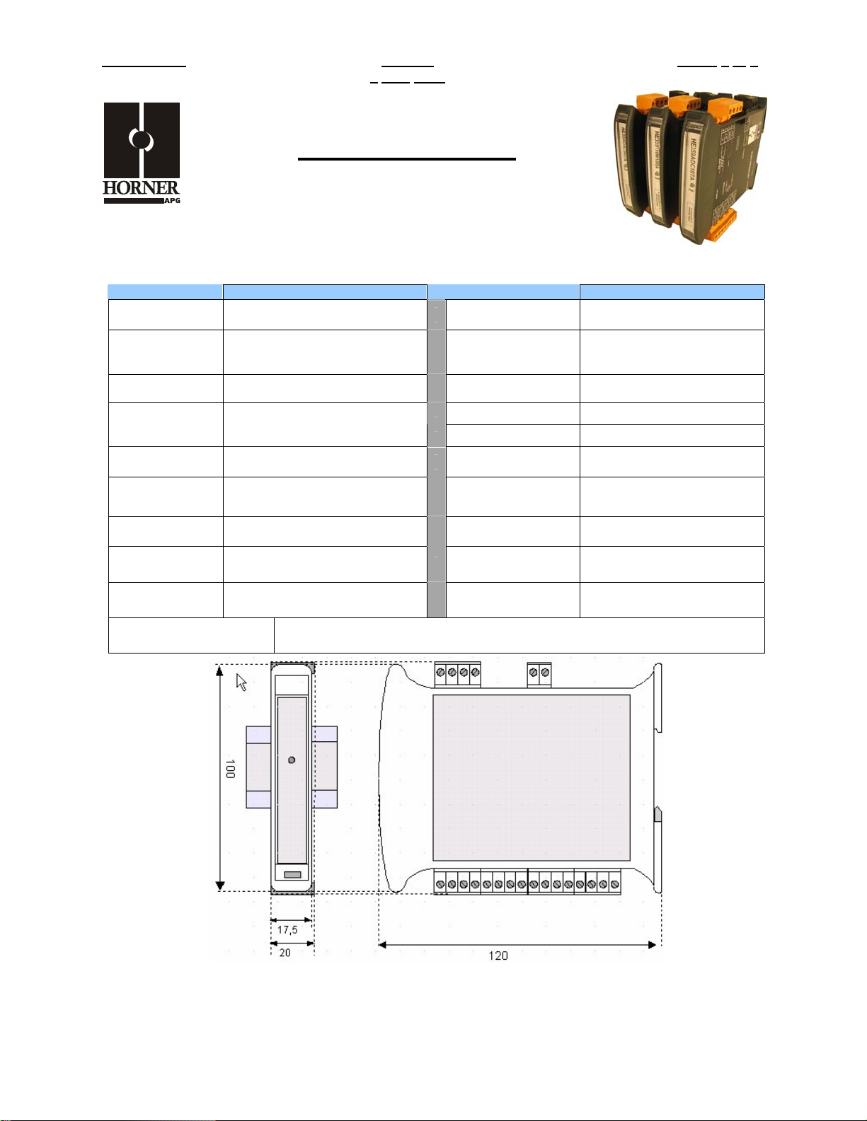
MAN0840-03 RTD100 PAGE 1 of 6
9
July 2007
RTD Input Module
0.1C or 0.1ohm Resolution
SmartMod
HE359RTD100
1 SPECIFICATIONS
RTD100 RTD100
Number of
Channels
Input Ranges
Resolution 0.1C or 0.1ohm Storage Temp.
RTD Excitation
Current
Accuracy +/-0.1% F.S. Dimensions WxHxD
External Power
Supply Voltage
Required Power
(Steady State)
Required Power
(Inrush)
Isolation
RTD Pt-100, Ni-100, Pt-1000, &
Ni-1000, 0-2000ohm, 0-500ohm
350microamp, typical
30mA @ 24Vdc, typical
2000Vac for 60 seconds
(Input/Power & Input/Comms)
4
(PT, .00385)
10-30Vdc
Negligible
Conversion Time
(PLC Update Rate)
Terminal Type Screw Type, Removable
Operating Temp.
Relative Humidity 5 to 95% Non-condensing
Weight 150g (6 oz.)
Communications
Default Comms.
Parameters
Supported Modbus
Commands
Determined by
Communications w/OCS
-40° to 85° Celsius
-10° to 60° Celsius
17.5mm x 100mm x 120mm
0.69” x 3.94” x 4.72”
Modbus/RTU (binary)
RS-485 half duplex
38400 baud, N, 8, 1, no h/s
Default Modbus ID 1
1,2,3,4,5,6,8,15,16
CE & UL Compliance See Compliance Table at http://www.heapg.com/Support/compliance.htm
Dimensions in inches are 0.69”W x 3.95”H x 4.72”D
Note: Number of I/O terminal connections vary from model to model
This document is the property of Horner APG and shall not be disclosed or reproduced except as specifically authorized.
Information is subject to change without notice.
Page 38
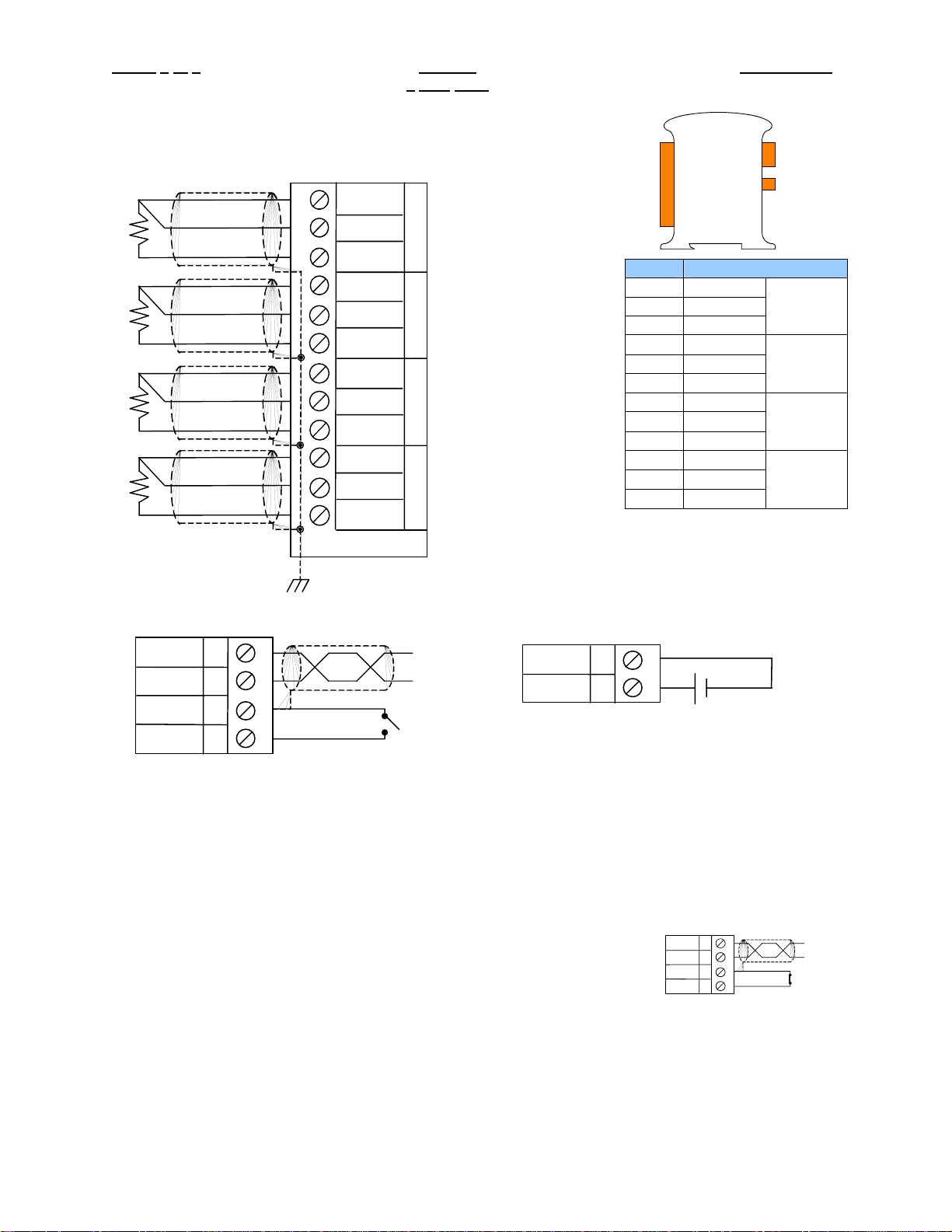
PAGE 2 of 6 RTD100 MAN0840-03
9
2 WIRING – I/O
1
2
3
4
5
6
7
8
9
10
11
12
GEN
IN
REF
GEN
IN
REF
GEN
IN
REF
GEN
IN
REF
July 2007
IN
0
IN
1
IN
2
IN
3
RS-485
I/O
Pin # RTD100
1 GEN
2 IN
3 REF
4 GEN
5 IN
6 REF
7 GEN
8 IN
9 REF
10 GEN
11 IN
12 REF
DC IN
IN 0
IN 1
IN 2
IN 3
WIRING – RS-485 WIRING – DC IN
Notes:
Both ends of the RS-485 network should be terminated with a 100ohm, 1/4W, 1% resistor. Many OCS
controllers feature dip switches or jumpers which enable appropriate termination if the OCS is located on
a network end..
When the INIT terminal is shorted to GND, factory default parameters are loaded into the module (RTU
mode, 38.4kbaud, N, 8, 1 with Modbus ID 1)
Init Default Setup:
1. Install jumper between INIT and GND terminals of the RS-485 port.
2. Apply power to Smartmod unit.
3. Read parameter words to see current parameters.
4. Write changes if necessary.
The INIT Default RS485 Settings Are:
Modbus ID = 1
Baud rate = 9600
Parity = None
Stop Bits = 1
DD+
GND
INIT
A
B
C
D
VV+
I
J
10-30Vdc
A
D-
B
D+
C
GND
INIT
D
This document is the property of Horner APG and shall not be disclosed or reproduced except as specifically authorized.
Information is subject to change without notice.
Page 39
MAN0840-03 RTD100 PAGE 3 of 6
9
July 2007
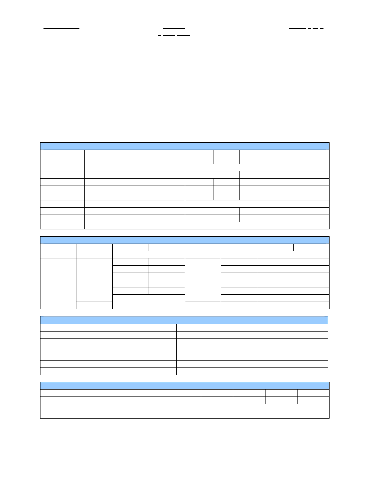
3 CONFIGURATION DATA
SmartMod Configuration settings are mapped into Modbus Register space. This configuration data may
be modified with any Modbus/RTU Master device. For convenience, Horner APG has developed a
variety of Cscape application files which allow an OCS (Xle, NX, LX, QX) to act as a SmartMod
configurator. Initial configuration of SmartMod module should be done on an individual basis, since all
modules come from the factory with a default Modbus ID of 1. Once each module on the network has its
own unique Modbus ID, further configuration adjustments can be made with the entire network powered.
All configuration parameters listed below (except 40012 Channel Enable) are stored in EPROM. That
means they should not be constantly rewritten.
Configuration Parameters – Registers 40001 through 40013
Modbus
Register
40001-40005 Reserved
40006 Communications Parameters See Table 38.4kbaud, N, 8, 1, RTU Mode
40007 Modbus ID 1 255 1
40008 Rx/Tx Delay (in 2mS steps) 0 255 0mS
40009 Watchdog Timer (in 0.5s steps) 0 255 10 (5s)
40010 Modbus Coil Data Not Configuration Data – See I/O Data
40011 Input Type See Table 23 (RTD Pt-100 Type)
40012 Channel Enable See Table 255 (All channels enabled)
40013 Reserved
Register 40006 (Communications Parameters) Bit Definition
Bits 7-15 Bit 6 Bit 5 Bit 4 Bit 3 Bit 2 Bit 1 Bit 0
Unused Mode Parity Data Bits Baud Rate
0 = ASCII
Mode
1 = RTU
Mode
Value Input Type
7 0-2000ohm Resistance
8 0-500ohm Resistance
23 RTD Pt-100 Type
24 RTD Ni-100 Type
25 RTD Pt-1000 Type
26 RTD Ni-1000 Type
Bit 4-15 Bit 3 Bit 2 Bit 1 Bit 0
Unused
Description
Value Meaning Value Meaning
0 Mark 0 1200 baud
1 Even
2 Odd 2 4800 baud
3 Space 3 9600 baud
Min
Max
Default
0 = 7 Data
Bits
1 2400 baud
1 = 8 Data
Bits
4 19200 baud
5-7 38400 baud
Register 40011 (Input Type) Value Definition
Register 40012 (Channel Enable) Bit Definition
Input 3 Input 2 Input 1 Input 0
0 = Disable Input
1 = Enable Input
This document is the property of Horner APG and shall not be disclosed or reproduced except as specifically authorized.
Information is subject to change without notice.
Page 40
PAGE 4 of 6 RTD100 MAN0840-03
9
July 2007
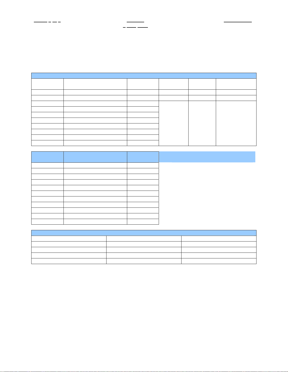
4 INPUT / OUTPUT DATA
SmartMod Analog I/O utilizes both Modbus Registers (40001-40030) and Coils (1-11). It is possible to
access all data using Registers only, because the Coils can be accessed through Register 40010.
The following tables lists all Modbus I/O data available.
I/O Register Data (Registers 40014-40022)
Modbus
Register
40010 Mirror of Coil Data Read/Write n/a n/a n/a
40014 Cold Junction Temperature Read-only -1000 6000 0.01 degrees C
40015 Input 0 Read-only
40016 Input 1 Read-only
40017 Input 2 Read-only
40018 Input 3 Read-only
40019 Input 4 Read-only
40020 Input 5 Read-only
40021 Input 6 Read-only
40022 Input 7 Read-only
Modbus
Coil
00001 Open Detect Input 0 Read/Write
00002 Open Detect Input 1 Read/Write
00003 Open Detect Input 2 Read/Write
00004 Open Detect Input 3 Read/Write
00005 Open Detect Input 4 Read/Write
00006 Open Detect Input 5 Read/Write
00007 Open Detect Input 6 Read/Write
00008 Open Detect Input 7 Read/Write
00009 Watchdog Enabled Read/Write
00010 Watchdog Event Read/Write
00011 Power-up Event Read/Write
RTD Sensor Type Minimum Temperature Maximum Temperature
Pt-100 -200 degrees C +850 degrees C
Ni-100 -80 degrees C +180 degrees C
Pt-1000 -200 degrees C +200 degrees C
Ni-1000 -60 degrees C +150 degrees C
Description
Description
Access
Minimum Maximum
Depends
on Input
Type
Watchdog Event & Power-up Event
Access
If Coil 9 (Watchdog Enabled) is set,
Coil 10 (Watchdog Event) will set if the
Watchdog Timeout value is exceeded.
The Watchdog Timeout value is set in
Register 40009. When set, Coil 10
can be reset by the controller when
normal communications resumes.
The Power-up Event (Coil 11) is set
every time the power is applied. It can
be cleared by the controller if desired.
RTD Sensor Temperature Ranges
Depends
on Input
Type
Operation
Units
0.1C or 0.1 ohm
This document is the property of Horner APG and shall not be disclosed or reproduced except as specifically authorized.
Information is subject to change without notice.
Page 41
MAN0840-03 RTD100 PAGE 5 of 6
9
July 2007
5 INSTALLATION / SAFETY
Warning: Remove power from the OCS controller, CAN port, and any peripheral equipment
connected to this local system before adding or replacing this or any module.
a. All applicable codes and standards should be followed in the installation of this product.
b. Shielded, twisted-pair wiring should be used for best performance.
c. Shields may be terminated at the module terminal strip.
d. In severe applications, shields should be tied directly to the ground block within the panel.
e. Use the following wire type or equivalent: Belden 8441.
For detailed installation and a handy checklist
clearances, refer to the hardware manual of the controller you are using. (See the Additional
References section in this document.)
When found on the product, the following symbols specify:
Warning: Consult user documentation.
that covers panel box layout requirements and minimum
Warning: Electrical Shock Hazard.
6 TECHNICAL SUPPORT
For assistance and manual up-dates, contact Technical Support at the following locations:
Helpdesk: http://www.horner-apg.com/helpdesk
North America:
(317) 916-4274
www.heapg.com
Europe:
(+) 353-21-4321-266
www.horner-apg.com
This document is the property of Horner APG and shall not be disclosed or reproduced except as specifically authorized.
Information is subject to change without notice.
Page 42

PAGE 6 of 6 RTD100 MAN0840-03
9
July 2007
NOTES
This document is the property of Horner APG and shall not be disclosed or reproduced except as specifically authorized.
Information is subject to change without notice.
Page 43
MAN0841-02 THM100/200 PAGE 1 of 7
15
MARCH 2007
Thermocouple Input Module
HE359THM100 / HE359THM200
0.1C or 0.001mV Resolution
SmartMod
1 SPECIFICATIONS
THM100 THM200 THM100 THM200
Number of
Channels
Input Ranges
Resolution 0.1C or 0.001mV Storage Temp.
4 8
J, K, R, S,B,E,T,N, +/-50mV,
+/-100mV, +/-500mV, +/-1V
Conversion Time
(PLC Update Rate)
Terminal Type Screw Type, Removable
Determined by
Communications w/OCS
-40° to 85° Celsius
Input Impedance >10MOhm
Accuracy +/-0.1% F.S. Dimensions WxHxD
External Power
Supply Voltage
Required Power
(Steady State)
Required Power
(Inrush)
Isolation
CE & UL Compliance See Compliance Table at http://www.heapg.com/Support/compliance.htm
(Input/Power & Input/Comms)
10-30Vdc
30mA @ 24Vdc, typical
Negligible
2000Vac for 60 seconds
Operating Temp.
Relative Humidity 5 to 95% Non-condensing
Weight 150g (6 oz.)
Communications
Default Comms.
Parameters
Supported Modbus
Commands
-10° to 60° Celsius
17.5mm x 100mm x 120mm
0.69” x 3.94” x 4.72”
Modbus/RTU (binary)
RS-485 half duplex
38400 baud, N, 8, 1, no h/s
Default Modbus ID 1
1,2,3,4,5,6,8,15,16
Dimensions in inches are 0.69”W x 3.95”H x 4.72”D
Note: Number of I/O terminal connections vary from model to model
Information is subject to change without notice.
Page 44
PAGE 2 of 7 THM100/200 MAN0841-02
15
2 WIRING – I/O
+
-
+
+
-
+
-
+
-
+
-
+
-
+
-
1
2
3
4
5
6
7
8
9
10
11
12
13
14
15
16
MARCH 2007
V+
IN
GNA
V+
GNA
V+
GNA
V+
GNA
V+
GNA
V+
GNA
V+
GNA
V+
GNA
0
IN
1
IN
2
IN
3
IN
4
IN
5
IN
6
IN
7
RS-485
I/O
Pin # ADC107 ADC207
1 INPUT 0+ INPUT 0+
2 ANALOG COMMON ANALOG COMMON
3 INPUT 1+ INPUT 1+
4 ANALOG COMMON ANALOG COMMON
5 INPUT 2+ INPUT 2+
6 ANALOG COMMON ANALOG COMMON
7 INPUT 3+ INPUT 3+
8 ANALOG COMMON ANALOG COMMON
9 INPUT 4+
10 ANALOG COMMON
11 INPUT 5+
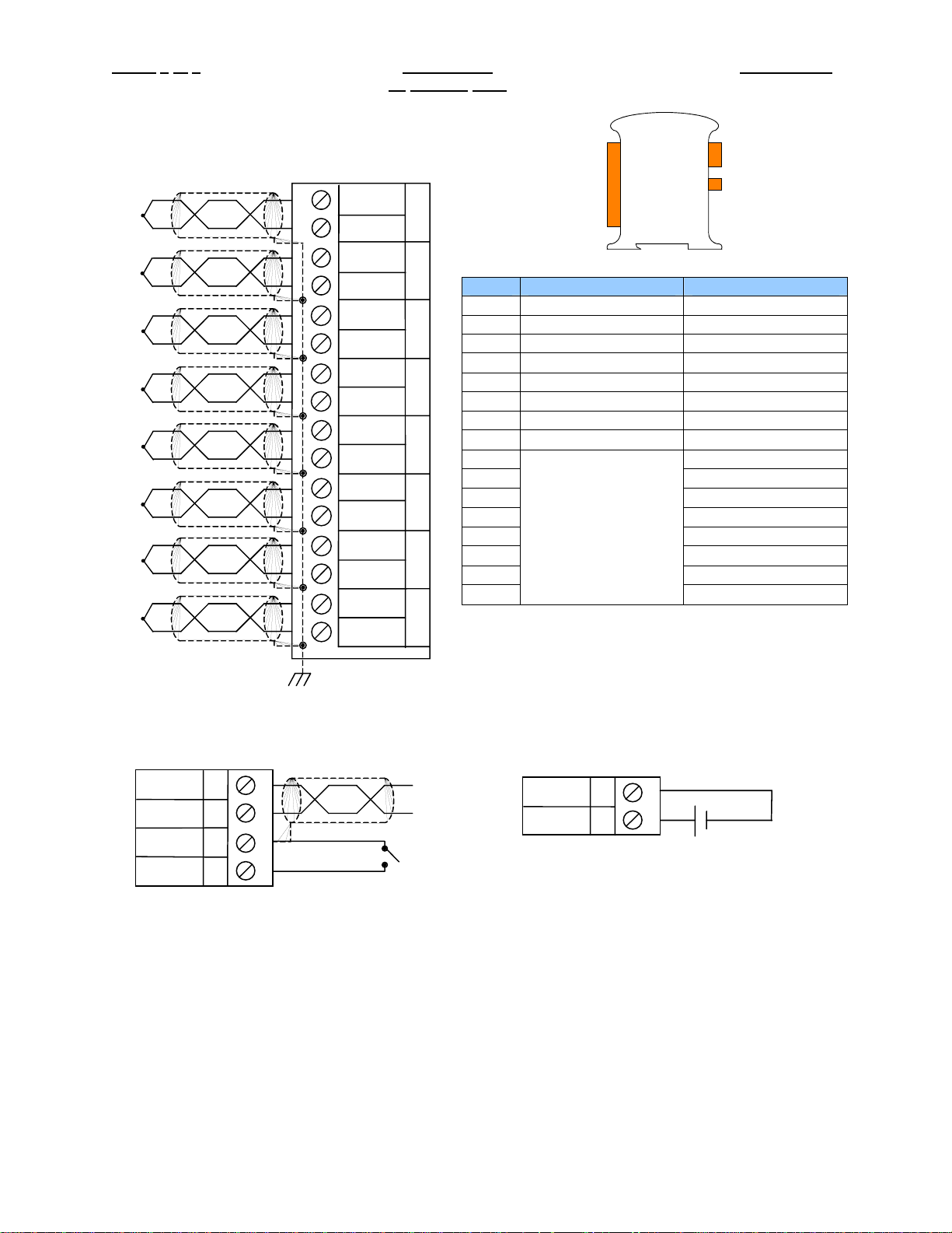
12 ANALOG COMMON
13 INPUT 6+
14 ANALOG COMMON
15 INPUT 7+
16
Only Terminals 1
through 8 are
present on the
ADC107 model
DC IN
ANALOG COMMON
WIRING – RS-485 WIRING – DC IN
DD+
GND
INIT
A
B
C
D
VV+
I
J
10-30Vdc
Information is subject to change without notice.
Page 45

MAN0841-02 THM100/200 PAGE 3 of 7
15
MARCH 2007
Notes:
Both ends of the RS-485 network should be terminated with a 100ohm, 1/4W, 1% resistor. Many OCS
controllers feature dip switches or jumpers which enable appropriate termination if the OCS is located on
a network end..
Init Default Setup:
1. Install jumper between INIT and GND terminals of the RS-485 port.
2. Apply power to Smartmod unit.
3. Read parameter words to see current parameters.
4. Write changes if necessary.
D-
D+
GND
INIT
A
B
C
D
The INIT Default RS485 Settings Are:
Modbus ID = 1
Baud rate = 9600
Parity = None
Stop Bits = 1
Information is subject to change without notice.
Page 46
PAGE 4 of 7 THM100/200 MAN0841-02
15
MARCH 2007
3 CONFIGURATION DATA
SmartMod Configuration settings are mapped into Modbus Register space. This configuration data may
be modified with any Modbus/RTU Master device. For convenience, Horner APG has developed a
variety of Cscape application files which allow an OCS (Xle, NX, LX, QX) to act as a SmartMod
configurator. Initial configuration of SmartMod module should be done on an individual basis, since all
modules come from the factory with a default Modbus ID of 1. Once each module on the network has its
own unique Modbus ID, further configuration adjustments can be made with the entire network powered.
All configuration parameters listed below (except 40012 Channel Enable) are stored in EPROM. That
means they should not be constantly rewritten.
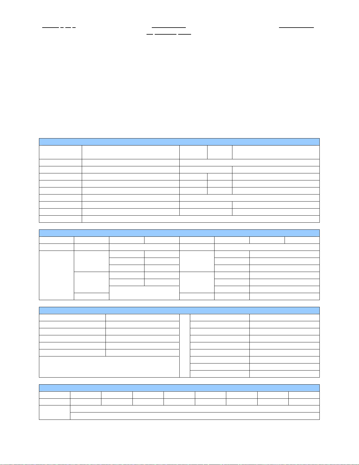
Configuration Parameters – Registers 40001 through 40013
Modbus
Register
40001-40005 Reserved
40006 Communications Parameters See Table 38.4kbaud, N, 8, 1, RTU Mode
40007 Modbus ID 1 255 1
40008 Rx/Tx Delay (in 2mS steps) 0 255 0mS
40009 Watchdog Timer (in 0.5s steps) 0 255 10 (5s)
40010 Modbus Coil Data Not Configuration Data – See I/O Data
40011 Input Type See Table 1 (+/-50mV)
40012 Channel Enable See Table 255 (Channels 1-8 enabled)
40013 Reserved
Register 40006 (Communications Parameters) Bit Definition
Bits 7-15 Bit 6 Bit 5 Bit 4 Bit 3 Bit 2 Bit 1 Bit 0
Unused Mode Parity Data Bits Baud Rate
0 = ASCII
Mode
1 = RTU
Mode
Value Input Type Value Input Type
1 +/-50mV 14 Type J T/C
2 +/-100mV 15 Type K T/C
3 +/-250mV 16 Type T T/C
4 +/-1000mV 17 Type E T/C
5-13 Not Used 18 Type R T/C
Bit 8-15 Bits 7 Bit 6 Bit 5 Bit 4 Bit 3 Bit 2 Bit 1 Bit 0
Unused Input 7 Input 6 Input 5 Input 4 Input 3 Input 2 Input 1 Input 0
Description
Value Meaning Value Meaning
0 Mark 0 1200 baud
1 Even
2 Odd 2 4800 baud
3 Space 3 9600 baud
Min
Max
Default
0 = 7 Data
Bits
1 2400 baud
1 = 8 Data
Bits
4 19200 baud
5-7 38400 baud
Register 40011 (Input Type) Value Definition
19 Type S T/C
20 Type B T/C
21 Type N T/C
Register 40012 (Channel Enable) Bit Definition
0 = Disable Input
1 = Enable Input
Information is subject to change without notice.
Page 47
MAN0841-02 THM100/200 PAGE 5 of 7
15
MARCH 2007
4 INPUT / OUTPUT DATA
SmartMod Analog I/O utilizes both Modbus Registers (40001-40030) and Coils (1-11). It is possible to
access all data using Registers only, because the Coils can be accessed through Register 40010.
The following tables lists all Modbus I/O data available.
I/O Register Data (Registers 40014-40022)
Modbus
Register
40010 Mirror of Coil Data Read/Write n/a n/a n/a
40014 Cold Junction Temperature Read-only -1000 6000 0.01 degrees C
40015 Input 0 Read-only 0.1C or 0.001mV
40016 Input 1 Read-only 0.1C or 0.001mV
40017 Input 2 Read-only 0.1C or 0.001mV
40018 Input 3 Read-only 0.1C or 0.001mV
40019 Input 4 Read-only 0.1C or 0.001mV
40020 Input 5 Read-only 0.1C or 0.001mV
40021 Input 6 Read-only 0.1C or 0.001mV
40022 Input 7 Read-only
Modbus
Coil
00001 Open Detect Input 0 Read/Write
00002 Open Detect Input 1 Read/Write
00003 Open Detect Input 2 Read/Write
00004 Open Detect Input 3 Read/Write
00005 Open Detect Input 4 Read/Write
00006 Open Detect Input 5 Read/Write
00007 Open Detect Input 6 Read/Write
00008 Open Detect Input 7 Read/Write
00009 Watchdog Enabled Read/Write
00010 Watchdog Event Read/Write
00011 Power-up Event Read/Write
Description
Description
Access
Access
Minimum Maximum
Depends
on Input
Type
Watchdog Event & Power-up Event
If Coil 9 (Watchdog Enabled) is set,
Coil 10 (Watchdog Event) will set if the
Watchdog Timeout value is exceeded.
The Watchdog Timeout value is set in
Register 40009. When set, Coil 10
can be reset by the controller when
normal communications resumes.
The Power-up Event (Coil 11) is set
every time the power is applied. It can
be cleared by the controller if desired.
Depends
on Input
Type
0.1C or 0.001mV
Operation
Units
5 INSTALLATION / SAFETY
Warning: Remove power from the OCS controller, CAN port, and any peripheral equipment
connected to this local system before adding or replacing this or any module.
a. All applicable codes and standards should be followed in the installation of this product.
b. Shielded, twisted-pair wiring should be used for best performance.
c. Shields may be terminated at the module terminal strip.
d. In severe applications, shields should be tied directly to the ground block within the panel.
e. Use the following wire type or equivalent: Belden 8441.
For detailed installation and a handy checklist
clearances, refer to the hardware manual of the controller you are using. (See the Additional
References section in this document.)
When found on the product, the following symbols specify:
Warning: Consult user documentation.
that covers panel box layout requirements and minimum
Warning: Electrical Shock Hazard.
Information is subject to change without notice.
Page 48

PAGE 6 of 7 THM100/200 MAN0841-02
15
MARCH 2007
6 TECHNICAL SUPPORT
For assistance and manual up-dates, contact Technical Support at the following locations:
Helpdesk: http://www.horner-apg.com/helpdesk
North America:
(317) 916-4274
www.heapg.com
Europe:
(+) 353-21-4321-266
www.horner-apg.com
Information is subject to change without notice.
Page 49

MAN0841-02 THM100/200 PAGE 7 of 7
15
MARCH 2007
NOTES
Information is subject to change without notice.
Page 50
MAN0895-01 Specifications / Installation
4.55 [115.6mm]
HE559-With Removable
Use this switch to set
Use this switch to set the
Power and Diagnostic
LEDs
INPUT
3 9 12 13 14 15 16 10
3 9 12 13 14 15 16 10
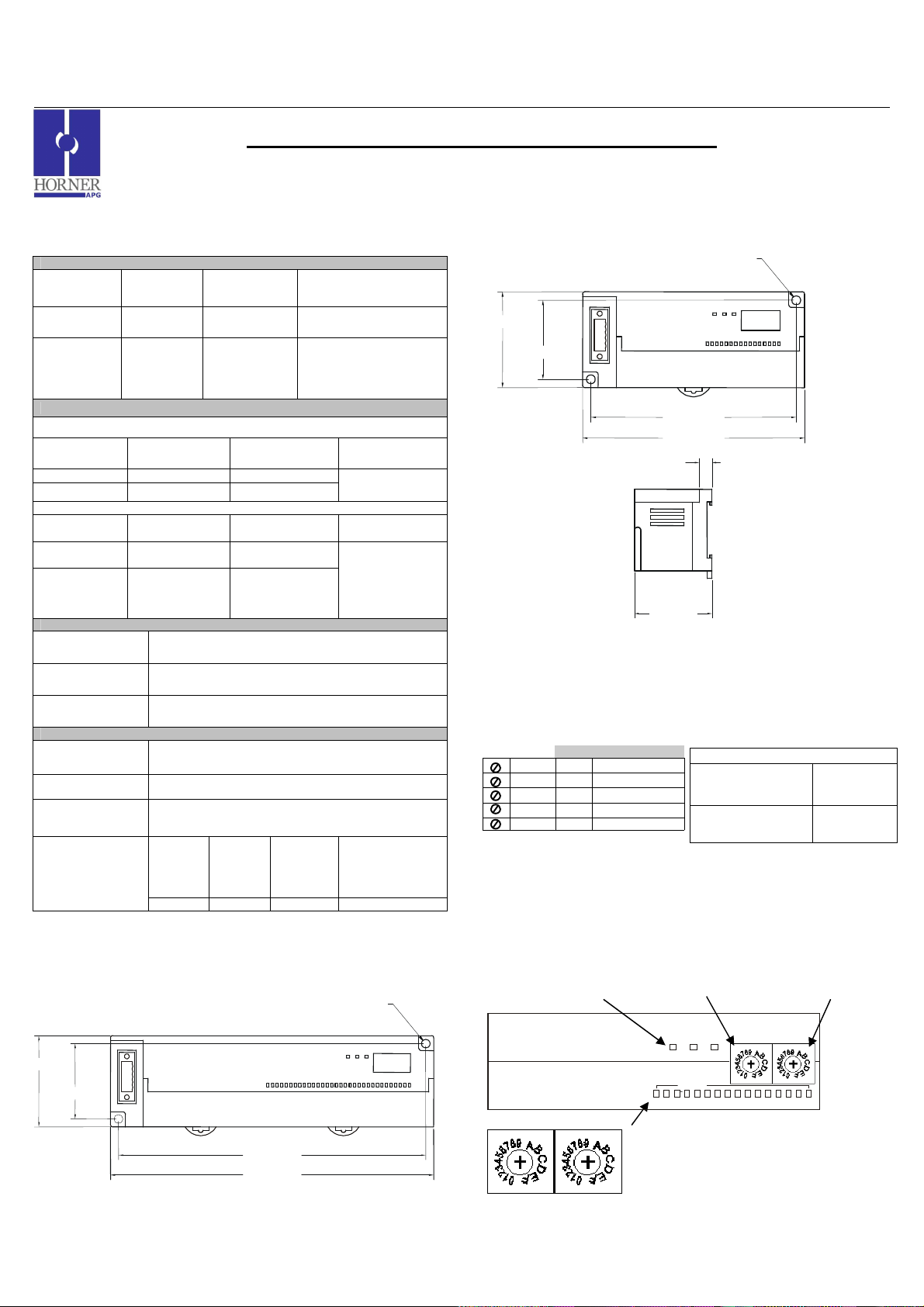
1 GENERAL SPECIFICATIONS
Storage
Temperature
Operating
Temperature
Atmosphere
Vibration
Frequency Acceleration Amplitude
10 ≤ f < 57 Hz
57 ≤ f ≤ 150 Hz
Frequency Acceleration Amplitude
10 ≤ f <
57 Hz
57≤ f ≤
150 Hz
Shocks
Maximum shock
acceleration
Duration Time 11 ms.
Pulse Wave Half sine wave pulse (3 times in each of X, Y, Z directions)
Noise Immunity
Square wave
impulse noise
Electrostatic
Discharge
Radiated
electromagnetic
field
Fast Transient
Burst Noise
16 DC Inputs (24VDC, positive/negative logic) / 32 DC Inputs (24VDC, positive/negative logic)
General Specifications
-25° to 70° C
0° to 55° C
Free from
corrosive
gases and
excessive
dust
Occasional Vibration
- 0.075 mm
9.8 m/s2 {1G} -
Continuous Vibration
- 0.035 mm
4.9 m/s2 {0.5G} -
Severity
level
Voltage 2 kV 1 kV 0.25 kV
SmartStixTM HE559DIM610/HE559DIM710
Remote I/O for the OCS/RCS Family
Operating and
Storage
Humidity
Pollution
degree
Cooling
method
147 m/s2 {15G}
AC: ± 1,500VDC
DC: ± 900VDC
Voltage: 4kV (contact discharge)
27 – 500MHz, 10V/m
All power
modules
5 to 95% Non-condensing
2 or lower
Self-cooling
10 times in each
direction for X,Y,Z
10 times in each
direction for X,Y,Z
Digital
I/Os
(Ue ≥24V)
Communication
Sweep
Count
Sweep
Count
Digital I/Os
(Ue < 24 V)
Analog I/Os
I/Os
2 DIMENSIONS
a. DIM710
0.18 [4.6mm]
1.97 [49.9mm]
1.62 [41.1mm]
6.61 [167.9mm]
6.95 [176.5mm]
b. DIM610
1.97 [49.9mm]
c. Terminal Strips
1.62 [41.1mm]
0.31
1.87
0.18 [4.6mm]
4.21 [106.9mm]
Strip
3 NETWORK CABLE
For detailed wiring information, refer to the Control Station Hardware Manual. A
handy checklist is provided that covers panel box layout requirements and minimum
clearances. See Section 10 for our web address.
Pin Description
RED 1 V+
WHT 2 CAN_H
NC 3 No Connection
BLU 4 CAN_L
BLK 5 V-
4 ID SWITCHES (SETTING CSCAN NETWORK IDs)
Recommended Cable
Thick:
(Max Distance =
500m)
Thin:
(Max Distance =
100m)
Belden 3082A
Belden 3084A
CsCAN Network IDs are set using the hexadecimal number system from 01 to FD. The
decimal equivalent is 1-253. Refer to Section 8, which shows the decimal equivalent of
hexadecimal numbers. Set a unique Network ID by inserting a small Phillips screwdriver
into the two identical switches. Note: The CsCAN Baud Rate for SmartStix I/O is fixed at
125KBaud
SmartStix I/O
SmartStix I/O
High Digit –has an x16
multiplier.
PWR
PWR
MS NS
MS NS
the Low Digit – has
an x1 multiplier.
HI (x16)
HI (x16)
LO (x1)
LO (x1)
I/O Status LEDs
INPUTS
2 1 4 5 6 7 8 11
2 1 4 5 6 7 8 11
Close-up of Switches
006DIM001
_________________________________________________________________________________________________________________
03/03/2009 Page 1 of 3 ECN # 952
Page 51
MAN0895-01 Specifications / Installation
To
Field
5 LEDs
a. Diagnostic LED Indicators
Diagnostic LED State Meaning
MS: (indicates fault status of
Module )
NS: (indicates fault status of
Network)
b. Status LED Indicators
The Power Status LED illuminates Red when power is applied to the module. There are
I/O Status LED indicators for each of the Digital I/O points, which illuminate Red when an
I/O point is ON.
Solid Red RAM or ROM test failed
Blinking Red I/O test failed
Blinking Green Module is in power-up state
Solid Green Module is running normally
Solid Red Network Ack or Dup ID test failed
Blinking Red Network ID test failed
Blinking Green
Solid Green Network is running normally
Module is in Life Expectancy default
state
6 WIRING
a. 16 DC IN, Positive Logic / Negative Logic
DIM610 Specifications
Number of input points 16
Rated Input Current
ON Voltage Level 19VDC or less Common
OFF Voltage Level 6VDC or less Operating
Input Characteristics Bidirectional
Isolation Method Photo Coupler
Rated Voltage 11 – 25 VDC Altitude for
Internal power
Consumption (mA)
7mA
200mA
24VDC
OFF to ON
Response
ON to OFF
Response
Terminal
Indicator
External
Connections
use
Weight 5.6 oz. (159 g)
NC
FG
NC
I1
I2
I3
I4
I5
I6
I7
I8
I9
I10
I11
I12
I13
I14
I15
I16
C
C
NC
006DIM005-R1
0 - 3ms. or less
0 - 3ms. or less
16 points / COM
LED turns on during
ON state of input
Terminal block
connector (M3 x 6
Up to 2,000m
Pin
NC*
FG Frame Ground
NC*
I1 Input 1
I2 Input 2
I3 Input 3
I4 Input 4
I5 Input 5
I6 Input 6
I7 Input 7
I8 Input 8
I9 Input 9
I10 Input 10
I11 Input 11
I12 Input 12
I13 Input 13
I14 Input 14
I15 Input 15
I16 Input 16
C Common
C Common
NC No Connection
screws)
Signal
DIM610
No Connection
(*Do not Connect)
No Connection
(*Do not Connect)
b. 32VDC IN, Positive Logic / Negative Logic
DIM710 INPUTS
Number of input
points
Rated Input Current 7mA ON to OFF Response 0 - 3ms. or less
ON Voltage Level 19VDC or less Common Terminal 16 points / COM
OFF Voltage Level 6VDC or less
Isolation Method Photo Coupler
Input
Characteristics
Rated Voltage 11 – 25 VDC
Internal power
Consumption (mA)
32
Bidirectional External Connections
300
24VDC
24VDC
OFF to ON Response 0 - 3ms. or less
Operating Indicator
Weight 8.36oz. (237 g)
NC
FG
NC
I1
I2
I3
I4
I5
I6
I7
I8
I9
I10
I11
I12
I13
I14
I15
I16
C1
I17
I18
I19
I20
I21
I22
I23
I24
I25
I26
I27
I28
I29
I30
I31
I32
C2
NC
006DIM006-R1
LED turns on
during ON state
of input
Terminal block
connector (M3 x
6 screws)
Pin
NC*
FG Frame Ground
NC*
I1 Input 1
I2 Input 2
I3 Input 3
I4 Input 4
I5 Input 5
I6 Input 6
I7 Input 7
I8 Input 8
I9 Input 9
I10 Input 10
I11 Input 11
I12 Input 12
I13 Input 13
I14 Input 14
I15 Input 15
I16 Input 16
C1 Isolated Common 1
I17 Input 17
I18 Input 18
I19 Input 19
I20 Input 20
I21 Input 21
I22 Input 22
I23 Input 23
I24 Input 24
I25 Input 25
I26 Input 26
I27 Input 27
I28 Input 28
I29 Input 29
I30 Input 30
I31 Input 31
I32 Input 32
C2 Isolated Common 2
NC No Connection
No Connection
(*Do not Connect)
No Connection
(*Do not Connect)
7 INTERNAL WIRING
a. DIM610
Field Side
I/O Connector
I1
SmartStix
VCC
C
b. DIM710
Side
I/O Connector
I1
Isolated
C1
SmartStix
VCC
Signal
DIM710
Controller
Controller
To
_________________________________________________________________________________________________________________
03/03/2009 Page 2 of 3 ECN # 952
Page 52
MAN0895-01 Specifications / Installation
Warning:
Consult user
Warning
: Wiring
the line side of the AC source to loads connected to outputs 0
Cscape, SmartStix and CsCAN are trademarks of Horner APG.
This information is
subject to change without notice.
8 DECIMAL (DEC) TO HEXADECIMAL (HEX) CONVERSION TABLE
Dec Hex Dec Hex Dec Hex
HI LO HI LO HI LO
0 0 0 86 5 6
1 0 1 87 5 7 173 A D
2 0 2 88 5 8 174 A E
3 0 3 89 5 9 175 A F
4 0 4 90 5 A 176 B 0
5 0 5 91 5 B 177 B 1
6 0 6 92 5 C 178 B 2
7 0 7 93 5 D 179 B 3
8 0 8 94 5 E 180 B 4
9 0 9 95 5 F 181 B 5
10 0 A 96 6 0 182 B 6
11 0 B 97 6 1 183 B 7
12 0 C 98 6 2 184 B 8
13 0 D 99 6 3 185 B 9
14 0 E 100 6 4 186 B A
15 0 F 101 6 5 187 B B
16 1 0 102 6 6 188 B C
17 1 1 103 6 7 189 B D
18 1 2 104 6 8 190 B E
19 1 3 105 6 9 191 B F
20 1 4 106 6 A 192 C 0
21 1 5 107 6 B 193 C 1
22 1 6 108 6 C 194 C 2
23 1 7 109 6 D 195 C 3
24 1 8 110 6 E 196 C 4
25 1 9 111 6 F 197 C 5
26 1 A 112 7 0 198 C 6
27 1 B 113 7 1 199 C 7
28 1 C 114 7 2 200 C 8
29 1 D 115 7 3 201 C 9
30 1 E 116 7 4 202 C A
31 1 F 117 7 5 203 C B
32 2 0 118 7 6 204 C C
33 2 1 119 7 7 205 C D
34 2 2 120 7 8 206 C E
35 2 3 121 7 9 207 C F
36 2 4 122 7 A 208 D 0
37 2 5 123 7 B 209 D 1
38 2 6 124 7 C 210 D 2
39 2 7 125 7 D 211 D 3
40 2 8 126 7 E 212 D 4
41 2 9 127 7 F 213 D 5
42 2 A 128 8 0 214 D 6
43 2 B 129 8 1 215 D 7
44 2 C 130 8 2 216 D 8
45 2 D 131 8 3 217 D 9
46 2 E 132 8 4 218 D A
47 2 F 133 8 5 219 D B
48 3 0 134 8 6 220 D C
49 3 1 135 8 7 221 D D
50 3 2 136 8 8 222 D E
51 3 3 137 8 9 223 D F
52 3 4 138 8 A 224 E 0
53 3 5 139 8 B 225 E 1
54 3 6 140 8 C 226 E 2
55 3 7 141 8 D 227 E 3
56 3 8 142 8 E 228 E 4
57 3 9 143 8 F 229 E 5
58 3 A 144 9 0 230 E 6
59 3 B 145 9 1 231 E 7
60 3 C 146 9 2 232 E 8
61 3 D 147 9 3 233 E 9
62 3 E 148 9 4 234 E A
63 3 F 149 9 5 235 E B
64 4 0 150 9 6 236 E C
65 4 1 151 9 7 237 E D
66 4 2 152 9 8 238 E E
67 4 3 153 9 9 239 E F
68 4 4 154 9 A 240 F 0
69 4 5 155 9 B 241 F 1
70 4 6 156 9 C 242 F 2
71 4 7 157 9 D 243 F 3
72 4 8 158 9 E 244 F 4
73 4 9 159 9 F 245 F 5
74 4 A 160 A 0 246 F 6
75 4 B 161 A 1 247 F 7
76 4 C 162 A 2 248 F 8
77 4 D 163 A 3 249 F 9
78 4 E 164 A 4 250 F A
79 4 F 165 A 5 251 F B
80 5 0 166 A 6 252 F C
81 5 1 167 A 7 253 F D
82 5 2 168 A 8 254 F E
83 5 3 169 A 9 255 F F
84 5 4 170 A A
85 5 5 171 A B
172
A C
9 INSTALLATION / SAFETY
a. All applicable codes and standards need to be followed in the installation of
this product.
b. For I/O wiring (discrete), use the following wire type or equivalent: Belden
8441 or equivalent.
c. For detailed installation information, refer to Chapter Two in the Control
Station Hardware Manual (MAN0227). A handy checklist is provided that
10 TECHNICAL ASSISTANCE
For assistance and manual updates, contact Technical Support at the following locations:
covers panel box layout requirements and minimum clearances.
documentation.
Warning: To protect the module and associated wiring from load faults, use
external fuse (5 A).
Warning: Connecting high voltage to any I/O pin may cause high voltage to
appear at other I/O pins.
through 15 and the neutral side of the AC source to the output common(s)
would create a Negative Logic condition, which may be considered an unsafe
practice.
North America:
Tel: 317 916-4274
Fax: 317 639-4279
Web: http://www.heapg.com
Email: [email protected]
Warning: Electrical Shock Hazard.
Europe:
Tel: +353-21-4321266
Fax: +353-21-4321826
Web: http://www.horner-apg.com
Email: [email protected]
_________________________________________________________________________________________________________________
03/03/2009 Page 3 of 3 ECN # 952
Page 53
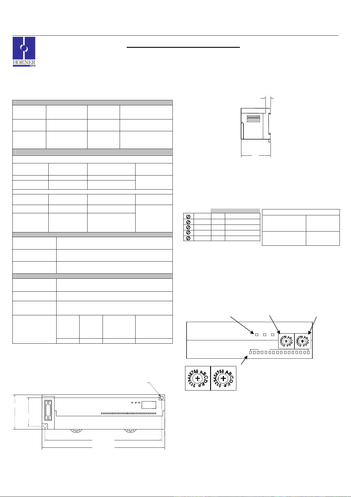
MAN0898-01 Specifications / Installation
1.87
0.31
HE559-With Removable
Use this switch to set
Use this switch to set the
ostic
LEDs
INPUT
MS NS
3 9 12 13 14 15 16 10
MS NS
3 9 12 13 14 15 16 10
1 GENERAL SPECIFICATIONS
Storage
Temperature
Operating
Temperature
Atmosphere
Vibration
Frequency Acceleration Amplitude
10 ≤ f < 57 Hz
57 ≤ f ≤ 150 Hz
Frequency Acceleration Amplitude
10 ≤ f < 57 Hz
57≤ f ≤ 150
Hz
Shocks
Maximum shock
acceleration
Duration Time 11 ms.
Pulse Wave Half sine wave pulse (3 times in each of X, Y, Z directions)
Noise Immunity
Square wave
impulse noise
Electrostatic
Discharge
Radiated
electromagnetic
field
Fast Transient
Burst Noise
16 DC Inputs (24VDC, positive logic), 16 DC Outputs (24VDC, positive logic, 0.5A)
General Specifications
-25° to 70° C
0° to 55° C
Free from corrosive
gases and
excessive dust
Occasional Vibration
- 0.075 mm
9.8 m/s2 {1G} -
Continuous Vibration
- 0.035 mm
4.9 m/s2 {0.5G} -
Severity
level
Voltage 2 kV 1 kV 0.25 kV
Operating
and Storage
Humidity
Pollution
degree
Cooling
method
147 m/s2 {15G}
AC: ± 1,500VDC
DC: ± 900VDC
Voltage: 4kV (contact discharge)
27 – 500MHz, 10V/m
All power
modules
SmartStixTM HE559DIQ816
Remote I/O for the OCS/RCS Family
5 to 95% Non-condensing
2 or lower
Self-cooling
Sweep
Count
10 times in each
direction for
X,Y,Z
Sweep
Count
10 times in each
direction for
X,Y,Z
Digital I/Os
Digital I/Os
(Ue ≥24V)
(Ue < 24 V)
Analog I/Os
Communication
I/Os
2 DIMENSIONS
a. DIQ816
0.18 [4.6mm]
1.97 [49.9mm]
1.62 [41.1mm]
6.61 [167.9mm]
6.95 [176.5mm]
__________________________________________________________________________________________________________________________________________________
03/02/2009 Page 1 of 3 ECN # 952
b. Terminal Strips
Strip
3 NETWORK CABLE
For detailed wiring information, refer to the Control Station Hardware Manual. A
handy checklist is provided that covers panel box layout requirements and minimum
clearances. See Section 10 for our web address.
Pin Description
RED 1 V+
WHT 2 CAN_H
NC 3 No Connection
BLU 4 CAN_L
BLK 5 V-
4 ID SWITCHES (SETTING CSCAN NETWORK IDs)
CsCAN Network IDs are set using the hexadecimal number system from 01 to FD. The
decimal equivalent is 1-253. Refer to Section 8, which shows the decimal equivalent of
hexadecimal numbers. Set a unique Network ID by inserting a small Phillips screwdriver
into the two identical switches. Note: The CsCAN Baud Rate for SmartStix I/O is fixed at
125KBaud.
Recommended Cable
Thick:
(Max Distance =
500m)
Thin:
(Max Distance =
100m)
Belden 3082A
Belden 3084A
Power and Diagn
SmartStix I/O
SmartStix I/O
High Digit –has an x16
multiplier.
PWR
PWR
the Low Digit – has
an x1 multiplier.
HI (x16)
HI (x16)
LO (x1)
LO (x1)
I/O Status LEDs
INPUTS
2 1 4 5 6 7 8 11
2 1 4 5 6 7 8 11
Close-up of Switches
006DIM001
Page 54
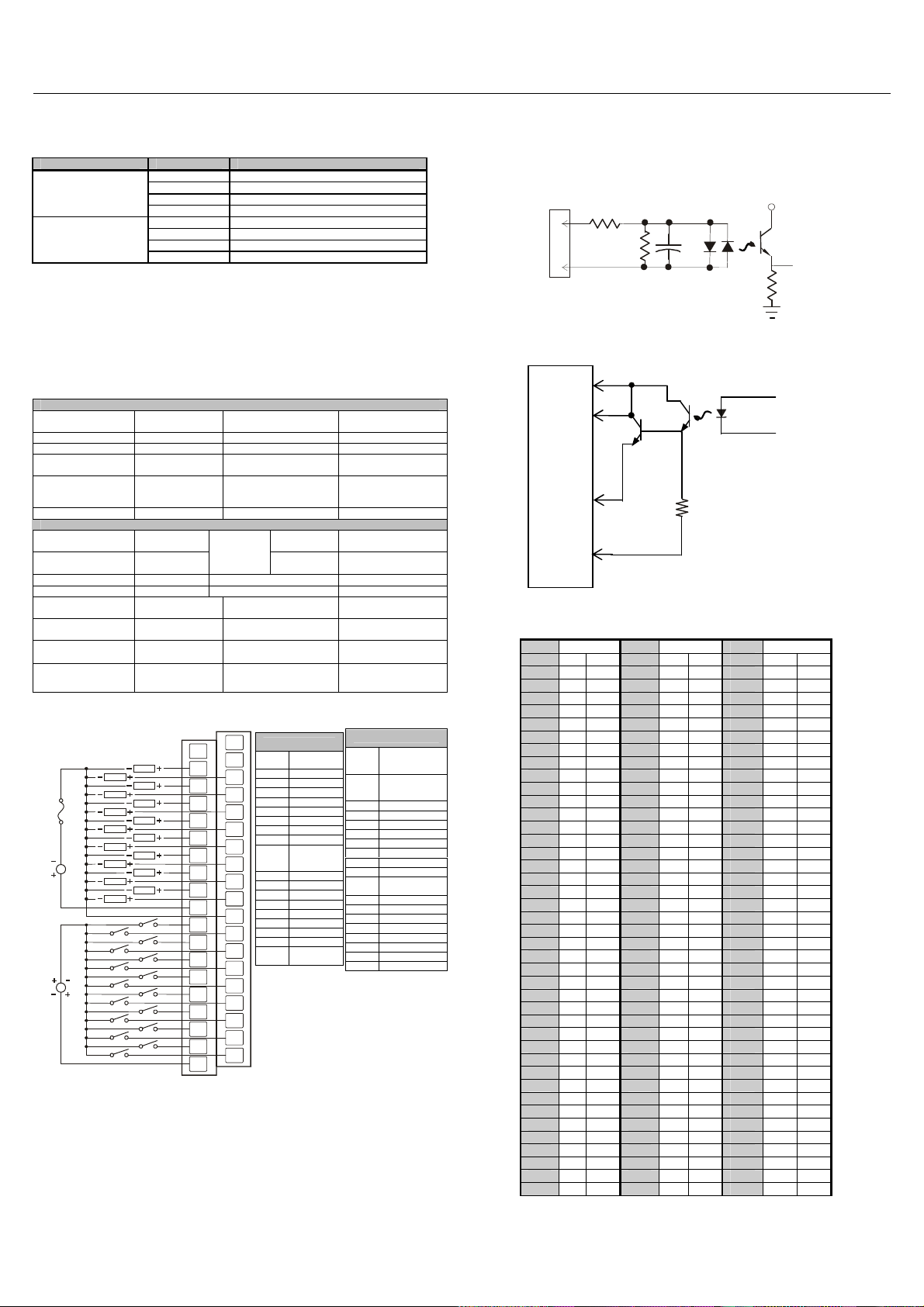
MAN0898-01 Specifications / Installation
To
Field Side
Field
From
5 LEDs
a. Diagnostic LED Indicators
Diagnostic LED State Meaning
MS: (indicates fault
status of Module )
NS: (indicates fault
status of Network)
b. Status LED Indicators
The Power Status LED illuminates Red when power is applied to the module. There are
I/O Status LED indicators for each of the Digital I/O points, which illuminate Red when an
I/O point is ON.
Solid Red RAM or ROM test failed
Blinking Red I/O test failed
Blinking Green Module is in power-up state
Solid Green Module is running normally
Solid Red Network Ack or Dup ID test failed
Blinking Red Network ID test failed
Blinking Green Module is in Life Expectancy default state
Solid Green Network is running normally
6 WIRING
a. 16 DC IN, Positive Logic/16 DC OUT, Positive Logic
DIQ816 IN
Number of input
points
Rated Input Current 7mA ON to OFF Response 0 - 3ms. or less
ON Voltage Level 19VDC or less Common Terminal 16 points / COM
OFF Voltage Level 6VDC or less Operating Indicator
Input
Characteristics
Isolation Method Photo Coupler
DIQ816 OUT
Number of output
points
Commons per
Module
Operating Voltage 24VDC OFF to ON Response 2ms.
Rated Load Voltage 24VDC ON to OFF Response 2ms.
OFF Leakage
Current
Rated Voltage 11 – 25 VDC
Internal power
Consumption (mA)
Common Method 16 points / COM Weight 10.16 oz. (288 g)
16 OFF to ON Response 0 - 3ms. or less
LED turns on during
ON state of input
Terminal block
Bidirectional External Connections
16 Voltage
1
0.1mA or less
350 Output Type Sourcing
External
Power
Supply
Max. Inrush Current
per channel
Max. Load Current per
channel
Current
connector (M3 x 6
24VDC ± 10%(ripple
voltage: 4Vp-p or less)
30mA (TYP, All points
0.5A Max. per output
3A per common
screws)
ON)
1A, 10ms
24VDC
LOAD
LOAD
LOAD
LOAD
LOAD
LOAD
LOAD
LOAD
LOAD
LOAD
LOAD
LOAD
LOAD
LOAD
LOAD
LOAD
24VDC
__________________________________________________________________________________________________________________________________________________
03/02/2009 Page 2 of 3 ECN # 952
FG
Q1
Q3
Q5
Q7
Q9
Q11
Q13
Q15
C1
I1
I3
I5
I7
I9
I11
I13
I15
C2
006DIQ004-R1
NC
NC
Q2
Q4
Q6
Q8
Q10
Q12
Q14
Q16
0V
I2
I4
I6
I8
I10
I12
I14
I16
DIQ816
FG*
Q1 Output 1
Q3 Output 3
Q5 Output 5
Q7 Output 7
Q9 Output 9
Q11 Output 11
Q13 Output 13
Q15 Output 15
C1
I1 Input 1
I3 Input 3
I5 Input 5
I7 Input 7
I9 Input 9
I11 Input 11
I13 Input 13
I15 Input 15
C2
Frame
Ground
Isolated
Common
Power
Isolated
Common
DIQ816
No Connection
NC*
(*Do not
Connect)
No Connection
NC*
(*Do not
Connect)
Q2 Output 2
Q4 Output 4
Q6 Output 6
Q8 Output 8
Q10 Output 10
Q12 Output 12
Q14 Output 14
Q16 Output 16
Isolated
0V
Ground
I2 Input 2
I4 Input 4
I6 Input 6
I8 Input 8
I10 Input 10
I12 Input 12
I14 Input 14
I16 Input 16
7 INTERNAL WIRING
Isolated
Common
Side
I/O Connector
I1
C2
I/O Connector
COM
Q16
Q1
Input
SmartStix
SmartStix
VCC
Controller
Controller
0V
8 DECIMAL (DEC) TO HEXADECIMAL (HEX) CONVERSION TABLE
Dec Hex Dec Hex Dec Hex
HI LO HI LO HI LO
0 0 0 86 5 6 172 A C
1 0 1 87 5 7 173 A D
2 0 2 88 5 8 174 A E
3 0 3 89 5 9 175 A F
4 0 4 90 5 A 176 B 0
5 0 5 91 5 B 177 B 1
6 0 6 92 5 C 178 B 2
7 0 7 93 5 D 179 B 3
8 0 8 94 5 E 180 B 4
9 0 9 95 5 F 181 B 5
10 0 A 96 6 0 182 B 6
11 0 B 97 6 1 183 B 7
12 0 C 98 6 2 184 B 8
13 0 D 99 6 3 185 B 9
14 0 E 100 6 4 186 B A
15 0 F 101 6 5 187 B B
16 1 0 102 6 6 188 B C
17 1 1 103 6 7 189 B D
18 1 2 104 6 8 190 B E
19 1 3 105 6 9 191 B F
20 1 4 106 6 A 192 C 0
21 1 5 107 6 B 193 C 1
22 1 6 108 6 C 194 C 2
23 1 7 109 6 D 195 C 3
24 1 8 110 6 E 196 C 4
25 1 9 111 6 F 197 C 5
26 1 A 112 7 0 198 C 6
27 1 B 113 7 1 199 C 7
28 1 C 114 7 2 200 C 8
29 1 D 115 7 3 201 C 9
30 1 E 116 7 4 202 C A
31 1 F 117 7 5 203 C B
32 2 0 118 7 6 204 C C
33 2 1 119 7 7 205 C D
34 2 2 120 7 8 206 C E
35 2 3 121 7 9 207 C F
36 2 4 122 7 A 208 D 0
37 2 5 123 7 B 209 D 1
38 2 6 124 7 C 210 D 2
39 2 7 125 7 D 211 D 3
40 2 8 126 7 E 212 D 4
Page 55
MAN0898-01 Specifications / Installation
Warning:
To protect the module and associated wiring from load faults, use exte
rnal
subject to change without notice.
41 2 9 127 7 F 213 D 5
42 2 A 128 8 0 214 D 6
43 2 B 129 8 1 215 D 7
44 2 C 130 8 2 216 D 8
45 2 D 131 8 3 217 D 9
46 2 E 132 8 4 218 D A
47 2 F 133 8 5 219 D B
48 3 0 134 8 6 220 D C
49 3 1 135 8 7 221 D D
50 3 2 136 8 8 222 D E
51 3 3 137 8 9 223 D F
52 3 4 138 8 A 224 E 0
53 3 5 139 8 B 225 E 1
54 3 6 140 8 C 226 E 2
55 3 7 141 8 D 227 E 3
56 3 8 142 8 E 228 E 4
57 3 9 143 8 F 229 E 5
58 3 A 144 9 0 230 E 6
59 3 B 145 9 1 231 E 7
60 3 C 146 9 2 232 E 8
61 3 D 147 9 3 233 E 9
62 3 E 148 9 4 234 E A
63 3 F 149 9 5 235 E B
64 4 0 150 9 6 236 E C
65 4 1 151 9 7 237 E D
66 4 2 152 9 8 238 E E
67 4 3 153 9 9 239 E F
68 4 4 154 9 A 240 F 0
69 4 5 155 9 B 241 F 1
70 4 6 156 9 C 242 F 2
71 4 7 157 9 D 243 F 3
72 4 8 158 9 E 244 F 4
73 4 9 159 9 F 245 F 5
74 4 A 160 A 0 246 F 6
75 4 B 161 A 1 247 F 7
76 4 C 162 A 2 248 F 8
77 4 D 163 A 3 249 F 9
78 4 E 164 A 4 250 F A
79 4 F 165 A 5 251 F B
80 5 0 166 A 6 252 F C
81 5 1 167 A 7 253 F D
82 5 2 168 A 8 254 F E
83 5 3 169 A 9 255 F F
84 5 4 170 A A
85 5 5 171 A B
9 INSTALLATION / SAFETY
a. All applicable codes and standards need to be followed in the installation of
this product.
b. For I/O wiring (discrete), use the following wire type or equivalent: Belden
8441 or equivalent.
c. For detailed installation information, refer to Chapter Two in the Control
Station Hardware Manual (MAN0227). A handy checklist is provided that
10 TECHNICAL ASSISTANCE
For assistance and manual updates, contact Technical Support at the following locations:
covers panel box layout requirements and minimum clearances.
Warning: Consult user
documentation.
Warning: Connecting high voltage to any I/O pin may cause high voltage to appear at
Warning: Wiring the line side of the AC source to loads connected to outputs 0
fuse (5 A).
other I/O pins.
through 15 and the neutral side of the AC source to the output common(s)
would create a Negative Logic condition, which may be considered an
Warning: Electrical Shock Hazard.
unsafe practice.
North America:
Tel: 317 916-4274
Fax: 317 639-4279
Web: http://www.heapg.com
Email: [email protected]
Europe:
Tel: +353-21-4321266
Fax: +353-21-4321826
Web: http://www.horner-apg.com
Email: [email protected]
Cscape, SmartStix and CsCAN are trademarks of Horner APG. This information is
__________________________________________________________________________________________________________________________________________________
03/02/2009 Page 3 of 3 ECN # 952
Page 56
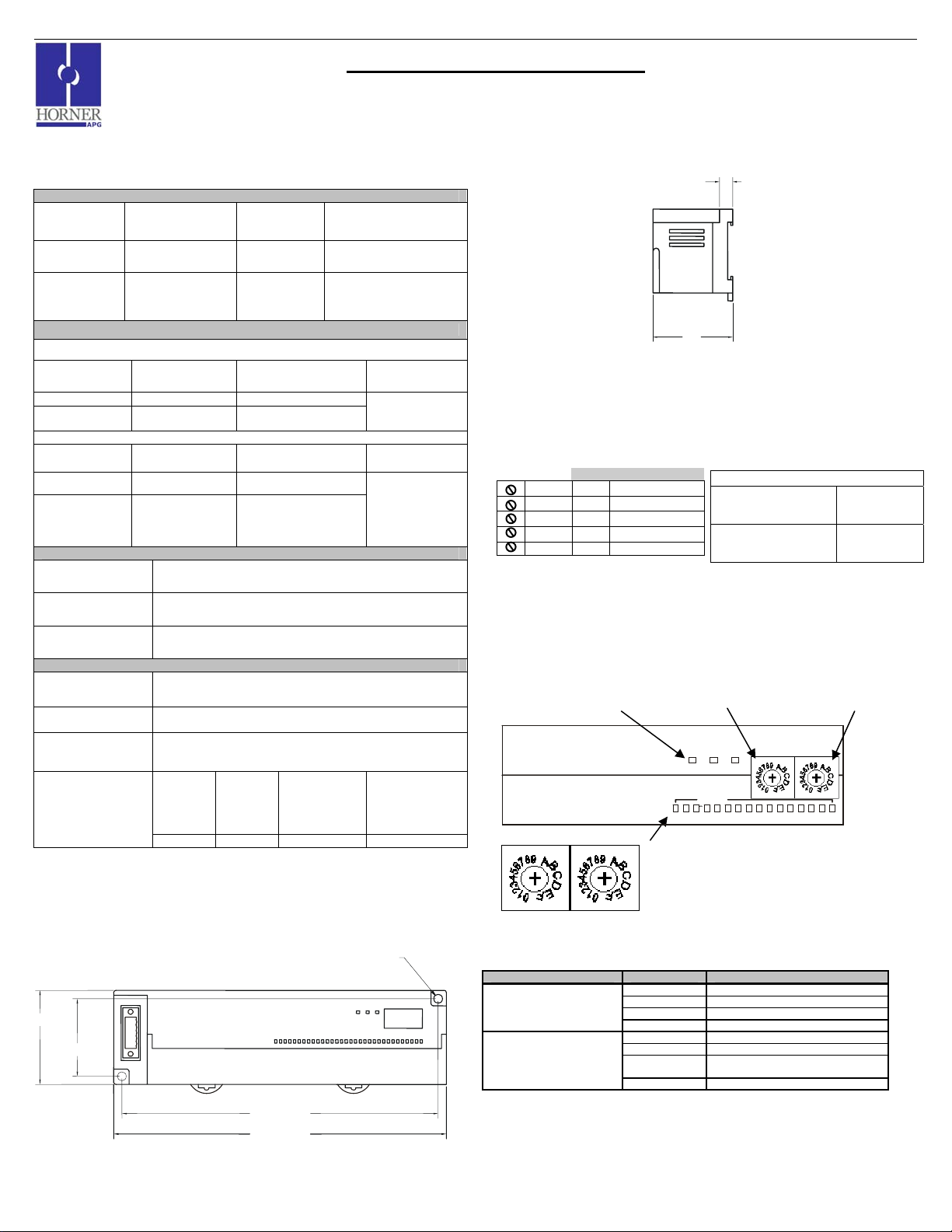
MAN0897-01 Specifications / Installation
)
1 GENERAL SPECIFICATIONS
Storage
Temperature
Operating
Temperature
Free from corrosive
Atmosphere
Vibration
Frequency Acceleration Amplitude
10 ≤ f < 57 Hz
57 ≤ f ≤ 150 Hz
Frequency Acceleration Amplitude
10 ≤ f < 57 Hz
57≤ f ≤ 150
Hz
Shocks
Maximum shock
acceleration
Duration Time 11 ms.
Pulse Wave Half sine wave pulse (3 times in each of X, Y, Z directions)
Noise Immunity
Square wave
impulse noise
Electrostatic
Discharge
Radiated
electromagnetic
field
Fast Transient
Burst Noise
excessive dust
General Specifications
-25° to 70° C
0° to 55° C
gases and
Occasional Vibration
- 0.075 mm
2
9.8 m/s
{1G} -
Continuous Vibration
- 0.035 mm
2
{0.5G} -
4.9 m/s
Severity
level
Voltage 2 kV 1 kV 0.25 kV
Operating
and Storage
Humidity
Pollution
degree
Cooling
method
147 m/s
AC: ± 1,500VDC
DC: ± 900VDC
Voltage: 4kV (contact discharge)
27 – 500MHz, 10V/m
All power
modules
Digital I/Os
(Ue ≥24V)
SmartStixTM HE559DQM602
Remote I/O for the OCS/RCS Family
16 Relay Outputs (250VAC, 30VDC, 2.0A
5 to 95% Non-condensing
2 or lower
Self-cooling
Sweep
Count
10 times in each
direction for
X,Y,Z
Sweep
Count
10 times in each
direction for
X,Y,Z
2
{15G}
Digital I/Os
(Ue < 24 V)
Analog I/Os
Communication
I/Os
2 DIMENSIONS
a. DQM602
0.18 [4.6mm]
1.97 [49.9mm]
1.62 [41.1mm]
6.61 [167.9mm]
6.95 [176.5mm]
b. Terminal Strips
0.31
1.87
HE559-With Removable
Strip
3 NETWORK CABLE
For detailed wiring information, refer to the Control Station Hardware Manual. A
handy checklist is provided that covers panel box layout requirements and minimum
clearances. See Section 10 for our web address.
Pin Description
RED 1 V+
WHT 2 CAN_H
NC 3 No Connection
BLU 4 CAN_L
BLK 5 V-
4 ID SWITCHES (SETTING CSCAN NETWORK IDs)
CsCAN Network IDs are set using the hexadecimal number system from 01 to FD. The
decimal equivalent is 1-253. Refer to Section 8, which shows the decimal equivalent of
hexadecimal numbers. Set a unique Network ID by inserting a small Phillips screwdriver
into the two identical switches. Note: The CsCAN Baud Rate for SmartStix I/O is fixed at
125KBaud.
Power and Diagnostic
LEDs
SmartStix I/O
SmartStix I/O
Use this switch to set the
High Digit –has an x16
multiplier.
MS
MS
Recommended Cable
Thick:
(Max Distance =
500m)
Thin:
(Max Distance =
100m)
NS PWR
NS PWR
Belden 3082A
Belden 3084A
Use this switch to set
the Low Digit – has
an x1 multiplier.
LO (x1)HI (x16)
LO (x1)HI (x16)
I/O Status LEDs
INPUTS
INPUT
2 1 4 5 6 7 8 113 9 12 13 14 15 1610
2 1 4 5 6 7 8 113 9 12 13 14 15 1610
Close-up of Switches
006DIM001
5 LEDs
a. Diagnostic LED Indicators
Diagnostic LED State Meaning
MS: (indicates fault status of
Module )
NS: (indicates fault status of
Network)
b. Status LED Indicators
The Power Status LED illuminates Red when power is applied to the module. There are
I/O Status LED indicators for each of the Digital I/O points, which illuminate Red when an
I/O point is ON.
Solid Red RAM or ROM test failed
Blinking Red I/O test failed
Blinking Green Module is in power-up state
Solid Green Module is running normally
Solid Red Network Ack or Dup ID test failed
Blinking Red Network ID test failed
Blinking Green
Solid Green Network is running normally
Module is in Life Expectancy default
state
______________________________________________________________________________________________________
03/02/2009 Page 1 of 2 ECN # 952
Page 57
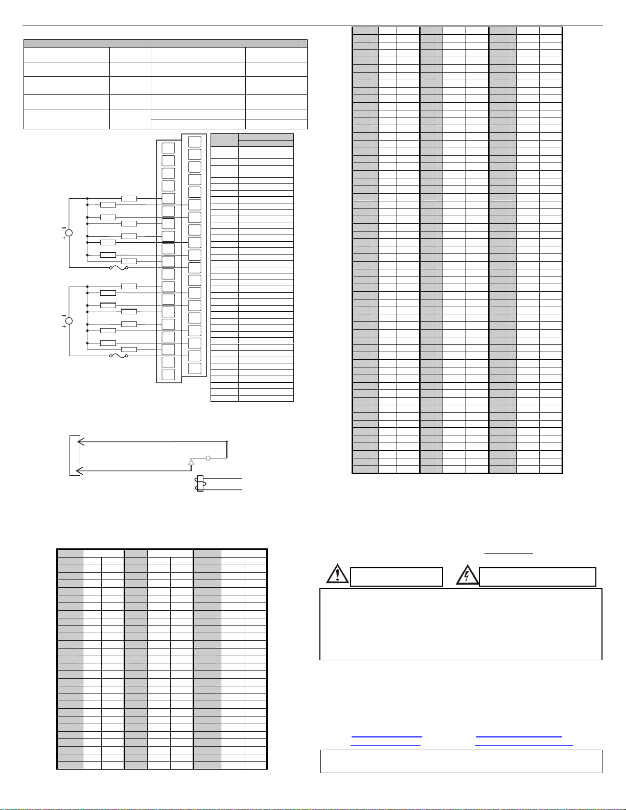
MAN0897-01 Specifications / Installation
j
6 WIRING
DQM602 Relay Outputs
Number of output points 16
Commons per Module 2
Rated Load Voltage
Rated Voltage
Internal power
Consumption (mA)
24VDC,
220VAC
11 – 25
VDC
550mA
220VAC
OR
24VDC
N
L
LOAD
LOAD
LOAD
LOAD
LOAD
LOAD
LOAD
LOAD
220VAC
OR
24VDC
N
L
LOAD
LOAD
LOAD
LOAD
LOAD
LOAD
LOAD
LOAD
7 INTERNAL WIRING
Field
Side
I/O Connector
C1
Q1
SmartStix
Specification for transient voltage suppressors (transorbs) used on output circuitry is
400VDC, bi-directional 400 watts.
Electro-mechanical relays comply with IEC1131-2.
Minimum load voltage /
current
Maximum Load Current
(resistive)
OFF to ON Response 10ms. Max.
ON to OFF Response 12ms. Max.
Output Type N.O.
Weight 9.91oz. (281 g)
FG
NC
NC
NC
Q1
C1
Q4
Q5
C1
Q8
NC
Q9
C2
Q12
Q13
C2
Q16
NC
NC
006DQM008-R1
NC
NC
NC
NC
NC
Q2
Q3
C1
Q6
Q7
C1
C1
Q10
Q11
C2
Q14
Q15
C2
C2
Pin
NC*
FG Frame Ground
NC*
NC No Connection
NC No Connection
NC No Connection
NC No Connection
NC No Connection
NC No Connection
Q1 Output 1
Q2 Output 2
C1 Common 1
Q3 Output 3
Q4 Output 4
C1 Common 1
Q5 Output 5
Q6 Output 6
C1 Common 1
Q7 Output 7
Q8 Output 8
C1 Common 1
NC No Connection
C1 Common 1
Q9 Output 9
Q10 Output 10
C2 Common 2
Q11 Output 11
Q12 Output 12
C2 Common 2
Q13 Output 13
Q14 Output 14
C2 Common 3
Q15 Output 15
Q16 Output 16
C2 Common 2
NC No Connection
C2 Common 2
NC No Connection
-
5VDC / 1mA
2.0A per channel
5.0A per common
Signal
DQM602
No Connection
(*Do not Connect)
No Connection
(*Do not Connect)
To
Controller
+
9 INSTALLATION / SAFETY
8 DECIMAL (DEC) TO HEXADECIMAL (HEX) CONVERSION TABLE
Dec Hex Dec Hex Dec Hex
HI LO HI LO HI LO
0 0 0 86 5 6 172 A C
1 0 1 87 5 7 173 A D
2 0 2 88 5 8 174 A E
3 0 3 89 5 9 175 A F
4 0 4 90 5 A 176 B 0
5 0 5 91 5 B 177 B 1
6 0 6 92 5 C 178 B 2
7 0 7 93 5 D 179 B 3
8 0 8 94 5 E 180 B 4
9 0 9 95 5 F 181 B 5
10 0 A 96 6 0 182 B 6
11 0 B 97 6 1 183 B 7
12 0 C 98 6 2 184 B 8
13 0 D 99 6 3 185 B 9
14 0 E 100 6 4 186 B A
15 0 F 101 6 5 187 B B
16 1 0 102 6 6 188 B C
17 1 1 103 6 7 189 B D
18 1 2 104 6 8 190 B E
19 1 3 105 6 9 191 B F
20 1 4 106 6 A 192 C 0
21 1 5 107 6 B 193 C 1
22 1 6 108 6 C 194 C 2
23 1 7 109 6 D 195 C 3
24 1 8 110 6 E 196 C 4
25 1 9 111 6 F 197 C 5
26 1 A 112 7 0 198 C 6
Warning: To protect the module and associated wiring from load faults, use external
Warning: Connecting high voltage to any I/O pin may cause high voltage to appear
Warning: Wiring the line side of the AC source to loads connected to outputs 0
10 TECHNICAL ASSISTANCE
For assistance and manual updates, contact Technical Support at the following locations:
North America:
Tel: 317 916-4274
Fax: 317 639-4279
Web:
Email:
Cscape, SmartStix and CsCAN are trademarks of Horner APG. This information is
sub
27 1 B 113 7 1 199 C 7
28 1 C 114 7 2 200 C 8
29 1 D 115 7 3 201 C 9
30 1 E 116 7 4 202 C A
31 1 F 117 7 5 203 C B
32 2 0 118 7 6 204 C C
33 2 1 119 7 7 205 C D
34 2 2 120 7 8 206 C E
35 2 3 121 7 9 207 C F
36 2 4 122 7 A 208 D 0
37 2 5 123 7 B 209 D 1
38 2 6 124 7 C 210 D 2
39 2 7 125 7 D 211 D 3
40 2 8 126 7 E 212 D 4
41 2 9 127 7 F 213 D 5
42 2 A 128 8 0 214 D 6
43 2 B 129 8 1 215 D 7
44 2 C 130 8 2 216 D 8
45 2 D 131 8 3 217 D 9
46 2 E 132 8 4 218 D A
47 2 F 133 8 5 219 D B
48 3 0 134 8 6 220 D C
49 3 1 135 8 7 221 D D
50 3 2 136 8 8 222 D E
51 3 3 137 8 9 223 D F
52 3 4 138 8 A 224 E 0
53 3 5 139 8 B 225 E 1
54 3 6 140 8 C 226 E 2
55 3 7 141 8 D 227 E 3
56 3 8 142 8 E 228 E 4
57 3 9 143 8 F 229 E 5
58 3 A 144 9 0 230 E 6
59 3 B 145 9 1 231 E 7
60 3 C 146 9 2 232 E 8
61 3 D 147 9 3 233 E 9
62 3 E 148 9 4 234 E A
63 3 F 149 9 5 235 E B
64 4 0 150 9 6 236 E C
65 4 1 151 9 7 237 E D
66 4 2 152 9 8 238 E E
67 4 3 153 9 9 239 E F
68 4 4 154 9 A 240 F 0
69 4 5 155 9 B 241 F 1
70 4 6 156 9 C 242 F 2
71 4 7 157 9 D 243 F 3
72 4 8 158 9 E 244 F 4
73 4 9 159 9 F 245 F 5
74 4 A 160 A 0 246 F 6
75 4 B 161 A 1 247 F 7
76 4 C 162 A 2 248 F 8
77 4 D 163 A 3 249 F 9
78 4 E 164 A 4 250 F A
79 4 F 165 A 5 251 F B
80 5 0 166 A 6 252 F C
81 5 1 167 A 7 253 F D
82 5 2 168 A 8 254 F E
83 5 3 169 A 9 255 F F
84 5 4 170 A A
85 5 5 171 A B
a. All applicable codes and standards need to be followed in the installation of
this product.
b. For I/O wiring (discrete), use the following wire type or equivalent: Belden
8441 or equivalent.
c. For detailed installation information, refer to Chapter Two in the Control
Station Hardware Manual (MAN0227). A
handy checklist is provided that
covers panel box layout requirements and minimum clearances.
Warning: Consult user
documentation.
Warning: Electrical Shock Hazard.
fuse (5 A).
at other I/O pins.
through 15 and the neutral side of the AC source to the output common(s)
would create a Negative Logic condition, which may be considered an
unsafe practice.
Europe:
Tel: +353-21-4321266
Fax: +353-21-4321826
http://www.heapg.com
Web:
http://www.horner-apg.com
Email: [email protected]
ect to change without notice.
______________________________________________________________________________________________________
03/02/2009 Page 2 of 2 ECN # 952
Page 58
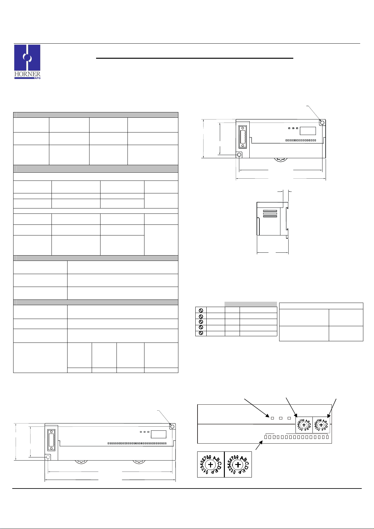
MAN0896-01 Specifications / Installation
HE559-With Removable
6.95 [176.5mm]
Use this switch to set
Use this switch
to set the
Power and Diagnostic
LEDs
INPUT
3 9 12 13 14 15 16 10
3 9 12 13 14 15 16 10
1 GENERAL SPECIFICATIONS
Storage
Temperature
Operating
Temperature
Atmosphere
Vibration
Frequency Acceleration Amplitude
10 ≤ f < 57 Hz
57 ≤ f ≤ 150 Hz
Frequency Acceleration Amplitude
10 ≤ f <
57 Hz
57≤ f ≤
150 Hz
Shocks
Maximum shock
acceleration
Duration Time 11 ms.
Pulse Wave
Square wave impulse
noise
Electrostatic
Discharge
Radiated
electromagnetic field
Fast Transient
Burst Noise
16 DC Outputs (24VDC, positive logic, 0.5A) / 32 DC Outputs (24VDC, positive logic, 0.5A)
General Specifications
-25° to 70° C
0° to 55° C
Free from
corrosive gases
and excessive
dust
Occasional Vibration
- 0.075 mm
9.8 m/s2 {1G} -
Continuous Vibration
- 0.035 mm
4.9 m/s2 {0.5G} -
Severity
level
Voltage 2 kV 1 kV 0.25 kV
SmartStixTM HE559DQM606/HE559DQM706
Remote I/O for the OCS/RCS Family
Operating and
Storage
Humidity
Pollution
degree
Cooling
method
147 m/s2 {15G}
Half sine wave pulse (3 times in each of X, Y, Z
Voltage: 4kV (contact discharge)
All power
directions)
AC: ± 1,500VDC
DC: ± 900VDC
27 – 500MHz, 10V/m
modules
Digital
I/Os
(Ue ≥24V)
5 to 95% Non-
condensing
2 or lower
Self-cooling
Sweep
Count
10 times in
each direction
for X,Y,Z
Sweep
Count
10 times in
each direction
for X,Y,Z
Digital I/Os
(Ue < 24 V)
Analog I/Os
Communicatio
n I/Os
2 DIMENSIONS
a. DQM706
0.18 [4.6mm]
1.97 [49.9mm]
1.62 [41.1mm]
03/02/2009 Page 1 of 3 ECN # 952
6.61 [167.9mm]
b. DQM606
1.97 [49.9mm]
c. Terminal Strips
1.62 [41.1mm]
0.18 [4.6mm]
4.21 [106.9mm]
4.55 [115.6mm]
0.31
1.87
Strip
3 NETWORK CABLE
For detailed wiring information, refer to the Control Station Hardware Manual. A
handy checklist is provided that covers panel box layout requirements and minimum
clearances. See Section 10 for our web address.
Pin Description
RED 1 V+
WHT 2 CAN_H
NC 3 No Connection
BLU 4 CAN_L
BLK 5 V-
4 ID SWITCHES (SETTING CSCAN NETWORK IDs)
CsCAN Network IDs are set using the hexadecimal number system from 01 to FD. The
decimal equivalent is 1-253. Refer to Section 8, which shows the decimal equivalent of
hexadecimal numbers. Set a unique Network ID by inserting a small Phillips screwdriver
into the two identical switches. Note: The CsCAN Baud Rate for SmartStix I/O is fixed at
125KBaud
Recommended Cable
Thick:
(Max Distance =
500m)
Thin:
(Max Distance =
100m)
Belden 3082A
Belden 3084A
SmartStix I/O
SmartStix I/O
High Digit –has an x16
multiplier.
PWR
PWR
MS NS
MS NS
the Low Digit – has
an x1 multiplier.
HI (x16)
HI (x16)
LO (x1)
LO (x1)
I/O Status LEDs
INPUTS
2 1 4 5 6 7 8 11
2 1 4 5 6 7 8 11
Close-up of Switches
006DIM001
Page 59
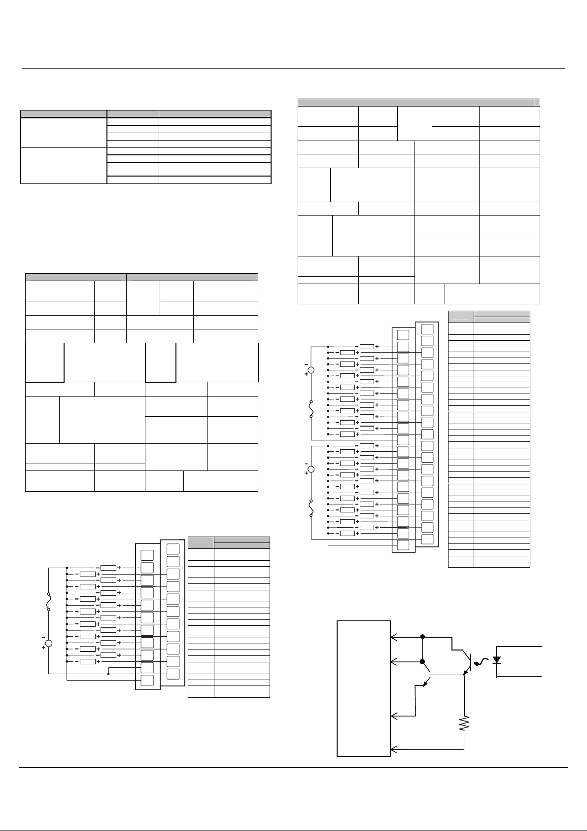
MAN0896-01 Specifications / Installation
006DQM008
-
R2
Note:
If desired, C1 and C2 can
Field
From
5 LEDs
a. Diagnostic LED Indicators
Diagnostic LED State Meaning
MS: (indicates fault status of
Module )
NS: (indicates fault status of
Network)
b. Status LED Indicators
The Power Status LED illuminates Red when power is applied to the module. There are
I/O Status LED indicators for each of the Digital I/O points, which illuminate Red when an
I/O point is ON.
Solid Red RAM or ROM test failed
Blinking Red I/O test failed
Blinking Green Module is in power-up state
Solid Green Module is running normally
Solid Red Network Ack or Dup ID test failed
Blinking Red Network ID test failed
Blinking Green
Solid Green Network is running normally
Module is in Life Expectancy default
state
6 WIRING
a. 16 DC OUT, Positive Logic
DQM606 Outputs
Number of output
points
Commons per
Module
Operating Voltage
Rated Load Voltage
Max.
Load
Current
per
channel
OFF Leakage
Current
Max.
Inrush
Current
per
channel
Maximum Voltage
Drop during ON
circuit
Rated Voltage 11 – 25 VDC
Internal power
Consumption (mA)
0.5A Max. per output 3A
16 Voltage
1
24VDC
24VDC
per common
0.1mA or less Common Method
1A, 10ms
1.5VDC(0.5A)
280 Weight 6.7 oz. (191g)
External
Power
Supply
OFF to ON
Response
ON to OFF
Response
Current
Output
Type
Operating Indicator
External
connections
Isolation methods Photo Coupler
24VDC ± 10% (ripple
voltage: 4Vp-p or
less)
30mA (TYP, All
points ON)
2ms.
2ms.
Sourcing
16 points /
COM
LED turns on
during ON
state of output
Terminal block
connector
(M3 x 6
screws)
24VDC
LOAD
LOAD
LOAD
LOAD
LOAD
LOAD
LOAD
LOAD
LOAD
LOAD
LOAD
LOAD
LOAD
LOAD
LOAD
LOAD
FG
Q1
Q3
Q5
Q7
Q9
Q11
Q13
Q15
COM
0V
006DQM007-R1
Pin
NC
NC*
NC
FG Frame Ground
NC*
Q2
Q1 Output 1
Q2 Output 2
Q4
Q3 Output 3
Q4 Output 4
Q6
Q5 Output 5
Q6 Output 6
Q8
Q7 Output 7
Q8 Output 8
Q10
Q9 Output 9
Q10 Output 10
Q12
Q11 Output 11
Q12 Output 12
Q14
Q13 Output 13
Q14 Output 14
Q16
Q15 Output 15
Q16 Output 16
COM
COM Isolated Common
COM Isolated Common
0V
Signal
DQM606
No Connection
(*Do not Connect)
No Connection
(*Do not Connect)
Isolated Power
Negative
b. 32 DC OUT, Positive Logic
DQM706 Outputs
Number of output
points
Commons per
Module
Operating Voltage
Rated Load
Voltage
Max.
Load
Current
per
channel
OFF Leakage
Current
Max.
Inrush
Current
per
channel
Maximum Voltage
Drop during ON
circuit
Rated Voltage 11 – 25 VDC
Internal power
Consumption
(mA)
0.5A Max. per output 3A per
1A, 10ms
24VDC
24VDC
LOAD
LOAD
LOAD
LOAD
LOAD
LOAD
LOAD
LOAD
LOAD
LOAD
LOAD
LOAD
LOAD
LOAD
LOAD
LOAD
use a single supply.
7 INTERNAL WIRING
a. DQM606
I/O Connector
COM
Side
Q1
32 Voltage
External
Power
Supply
2
24VDC
24VDC
common
0.1mA or less Common Method 16 points / COM
1.5VDC(0.5A)
380 Weight 10.22 (290g)
FG
LOAD
LOAD
LOAD
LOAD
LOAD
LOAD
LOAD
LOAD
LOAD
LOAD
LOAD
LOAD
LOAD
LOAD
LOAD
LOAD
Q1
Q3
Q5
Q7
Q9
Q11
Q13
Q15
C1
Q18
Q20
Q22
Q24
Q26
Q28
Q30
Q32
0V
Current
OFF to ON
Response
ON to OFF
Response
Output Type Sourcing
Operating Indicator LED turns on
External
connections
Isolation methods Photo Coupler
NC
NC
Q2
Q4
Q6
Q8
Q10
Q12
Q14
Q16
Q17
Q19
Q21
Q23
Q25
Q27
Q29
Q31
C2
24VDC ±
10%(ripple voltage:
4Vp-p or less)
30mA (TYP, All
points ON)
2ms.
2ms.
during ON state of
output
Terminal block
connector
(M3 x 6 screws)
Pin
NC*
FG* Frame Ground
NC*
Q1 Output 1
Q2 Output 2
Q3 Output 3
Q4 Output 4
Q5 Output 5
Q6 Output 6
Q7 Output 7
Q8 Output 8
Q9 Output 9
Q10 Output 10
Q11 Output 11
Q12 Output 12
Q13 Output 13
Q14 Output 14
Q15 Output 15
Q16 Output 16
C1 Isolated Common 1
Q17 Output 17
Q18 Output 18
Q19 Output 19
Q20 Output 20
Q21 Output 21
Q22 Output 22
Q23 Output 23
Q24 Output 24
Q25 Output 25
Q26 Output 26
Q27 Output 27
Q28 Output 28
Q29 Output 29
Q30 Output 30
Q31 Output 31
Q32 Output 32
C2 Isolated Common 2
0V
SmartStix
Signal
DQM706
No Connection
(*Do not Connect)
No Connection
(*Do not Connect)
Isolated Power
Negative
Q16
0V
Controller
03/02/2009 Page 2 of 3 ECN # 952
Page 60
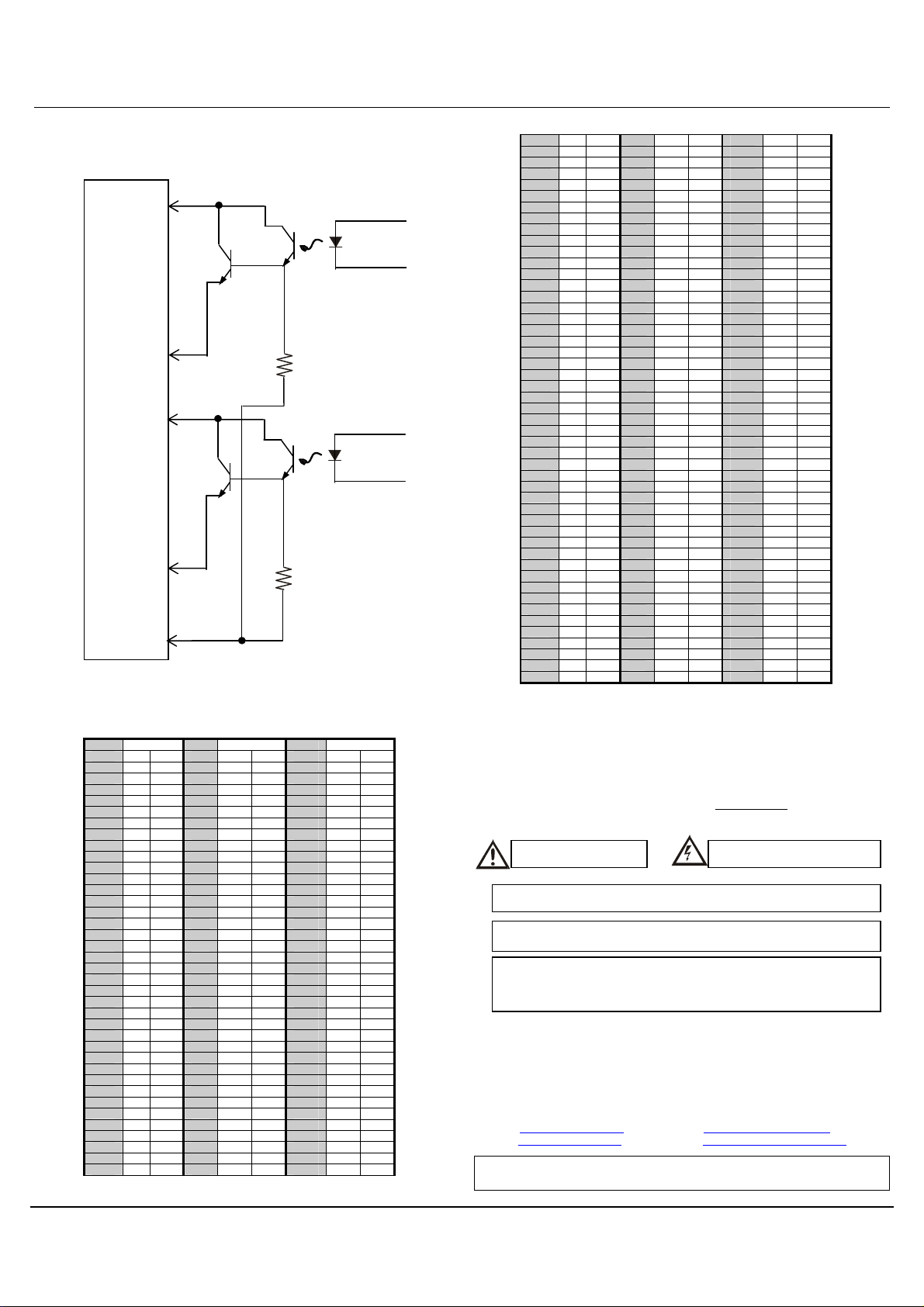
MAN0896-01 Specifications / Installation
Warning
: Connecting high voltage to any I/O pin may cause high voltage to
subject to change without notice.
Field
Q17 – Q32
From
From
Q1 – Q16
b. DQM706
I/O Connector
C1
SmartStix
Controller
Side
Typical
C2
Controller
Typical
0V
8 DECIMAL (DEC) TO HEXADECIMAL (HEX) CONVERSION TABLE
Dec Hex Dec Hex Dec Hex
HI LO HI LO HI LO
0 0 0 86 5 6
1 0 1 87 5 7 173 A D
2 0 2 88 5 8 174 A E
3 0 3 89 5 9 175 A F
4 0 4 90 5 A 176 B 0
5 0 5 91 5 B 177 B 1
6 0 6 92 5 C 178 B 2
7 0 7 93 5 D 179 B 3
8 0 8 94 5 E 180 B 4
9 0 9 95 5 F 181 B 5
10 0 A 96 6 0 182 B 6
11 0 B 97 6 1 183 B 7
12 0 C 98 6 2 184 B 8
13 0 D 99 6 3 185 B 9
14 0 E 100 6 4 186 B A
15 0 F 101 6 5 187 B B
16 1 0 102 6 6 188 B C
17 1 1 103 6 7 189 B D
18 1 2 104 6 8 190 B E
19 1 3 105 6 9 191 B F
20 1 4 106 6 A 192 C 0
21 1 5 107 6 B 193 C 1
22 1 6 108 6 C 194 C 2
23 1 7 109 6 D 195 C 3
24 1 8 110 6 E 196 C 4
25 1 9 111 6 F 197 C 5
26 1 A 112 7 0 198 C 6
27 1 B 113 7 1 199 C 7
28 1 C 114 7 2 200 C 8
29 1 D 115 7 3 201 C 9
30 1 E 116 7 4 202 C A
31 1 F 117 7 5 203 C B
32 2 0 118 7 6 204 C C
33 2 1 119 7 7 205 C D
34 2 2 120 7 8 206 C E
35 2 3 121 7 9 207 C F
36 2 4 122 7 A 208 D 0
172
A C
37 2 5 123 7 B 209 D 1
38 2 6 124 7 C 210 D 2
39 2 7 125 7 D 211 D 3
40 2 8 126 7 E 212 D 4
41 2 9 127 7 F 213 D 5
42 2 A 128 8 0 214 D 6
43 2 B 129 8 1 215 D 7
44 2 C 130 8 2 216 D 8
45 2 D 131 8 3 217 D 9
46 2 E 132 8 4 218 D A
47 2 F 133 8 5 219 D B
48 3 0 134 8 6 220 D C
49 3 1 135 8 7 221 D D
50 3 2 136 8 8 222 D E
51 3 3 137 8 9 223 D F
52 3 4 138 8 A 224 E 0
53 3 5 139 8 B 225 E 1
54 3 6 140 8 C 226 E 2
55 3 7 141 8 D 227 E 3
56 3 8 142 8 E 228 E 4
57 3 9 143 8 F 229 E 5
58 3 A 144 9 0 230 E 6
59 3 B 145 9 1 231 E 7
60 3 C 146 9 2 232 E 8
61 3 D 147 9 3 233 E 9
62 3 E 148 9 4 234 E A
63 3 F 149 9 5 235 E B
64 4 0 150 9 6 236 E C
65 4 1 151 9 7 237 E D
66 4 2 152 9 8 238 E E
67 4 3 153 9 9 239 E F
68 4 4 154 9 A 240 F 0
69 4 5 155 9 B 241 F 1
70 4 6 156 9 C 242 F 2
71 4 7 157 9 D 243 F 3
72 4 8 158 9 E 244 F 4
73 4 9 159 9 F 245 F 5
74 4 A 160 A 0 246 F 6
75 4 B 161 A 1 247 F 7
76 4 C 162 A 2 248 F 8
77 4 D 163 A 3 249 F 9
78 4 E 164 A 4 250 F A
79 4 F 165 A 5 251 F B
80 5 0 166 A 6 252 F C
81 5 1 167 A 7 253 F D
82 5 2 168 A 8 254 F E
83 5 3 169 A 9 255 F F
84 5 4 170 A A
85 5 5 171 A B
9 INSTALLATION / SAFETY
a. All applicable codes and standards need to be followed in the installation of
this product.
b. For I/O wiring (discrete), use the following wire type or equivalent: Belden
8441 or equivalent.
c. For detailed installation information, refer to Chapter Two in the Control
Station Hardware Manual (MAN0227). A handy checklist is provided that
covers panel box layout requirements and minimum clearances.
Warning: Consult user
documentation.
Warning: To protect the module and associated wiring from load faults, use
external fuse (5 A).
Warning: Electrical Shock Hazard.
appear at other I/O pins.
Warning: Wiring the line side of the AC source to loads connected to outputs 0
through 15 and the neutral side of the AC source to the output
common(s) would create a Negative Logic condition, which may be
considered an unsafe practice.
10 TECHNICAL ASSISTANCE
For assistance and manual updates, contact Technical Support at the following locations:
North America:
Tel: 317 916-4274
Fax: 317 639-4279
Web: http://www.heapg.com
Email: [email protected]
Cscape, SmartStix and CsCAN are trademarks of Horner APG. This information is
Europe:
Tel: +353-21-4321266
Fax: +353-21-4321826
Web: http://www.horner-apg.com
Email: [email protected]
03/02/2009 Page 3 of 3 ECN # 952
Page 61
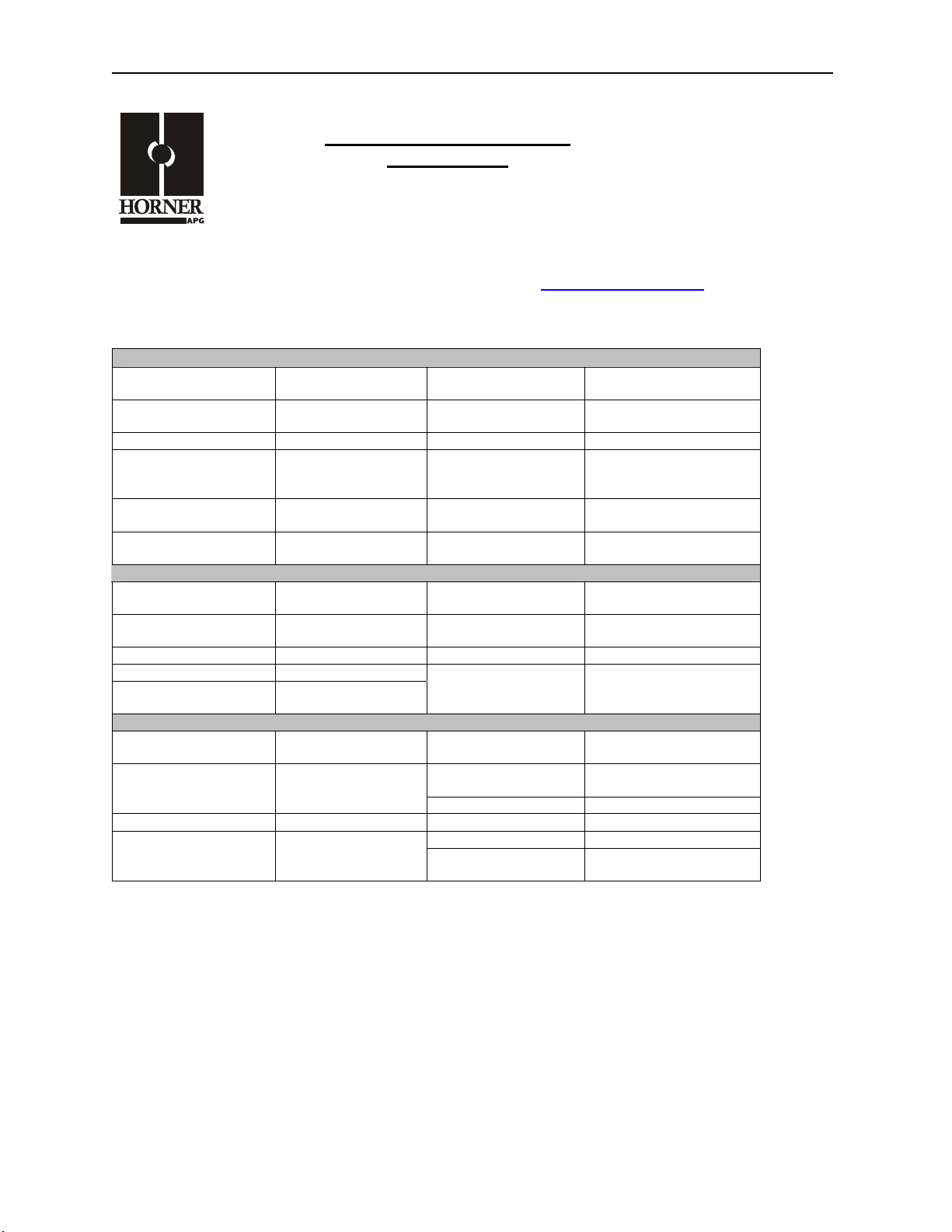
MIX577 07 APR 2006 Page 1
x
Analog I/O Module
HE559MIX577
4 Input Channels
2 Output Channels
±5V / ±10V / 4-20mA / ±20mA
CsCAN
SmartSti
Refer to SmartStix Analog Programming Guide (MAN0703) at www.HornerOCS.com
1 SPECIFICATIONS
ANALOG IN
Number of input
points
Input Ranges
Resolution
Accuracy, 25°C
Input Impedance
Register Value for
Nominal Full Scale
ANALOG OUT
Number of output
points
Input Ranges
Resolution
Accuracy, 25°C
Load Resistance
GENERAL
Required Power
(Steady State)
Required Power
(Inrush)
Storage Temperature
Atmosphere
4
±5V, ±10V DC
4-20mA, ±20mA DC
14 bits
0.3%
V: 1 Megohm
mA: 150 Ohms
32000
2
±5, ±10V DC
4-20mA, ±20mA DC
14 bits
0.3%
V: 600 Min
mA: 500 Max
3.6W
(150ma @ 24VDC)
8A @ 24VDC for
1ms
-25° to 70° C
Free from corrosive
gases and excessive
dust
Conversion Time
Isolation
Isolation Method
Maximum
Continuous
Overload
Programmable Filter
Time Constants
Filter Modes
Isolation
Isolation Method
Output Clamp
Register Value for
Nominal Full Scale
Operating
Temperature
Operating and
Storage Humidity
Altitude for use
Pollution degree
Cooling method
Weight
5mS for all Channels
1000V DC
IEC61010-1 300V RMS
Magnetic
±10V: 150VAC
±20mA: ±30mA,
Clamped at ±6V
0.01 to 1.28 Seconds
Running Average or
Adaptive
1000V DC
IEC61010-1 300V RMS
Magnetic
±12V, 600Wpk
32000
0° to 55° C
5 to 95% Non-
condensing
Up to 2,000m
2 or lower
Self-cooling
8.40 oz. (238 g)
.
MAN0708-01
Page 62
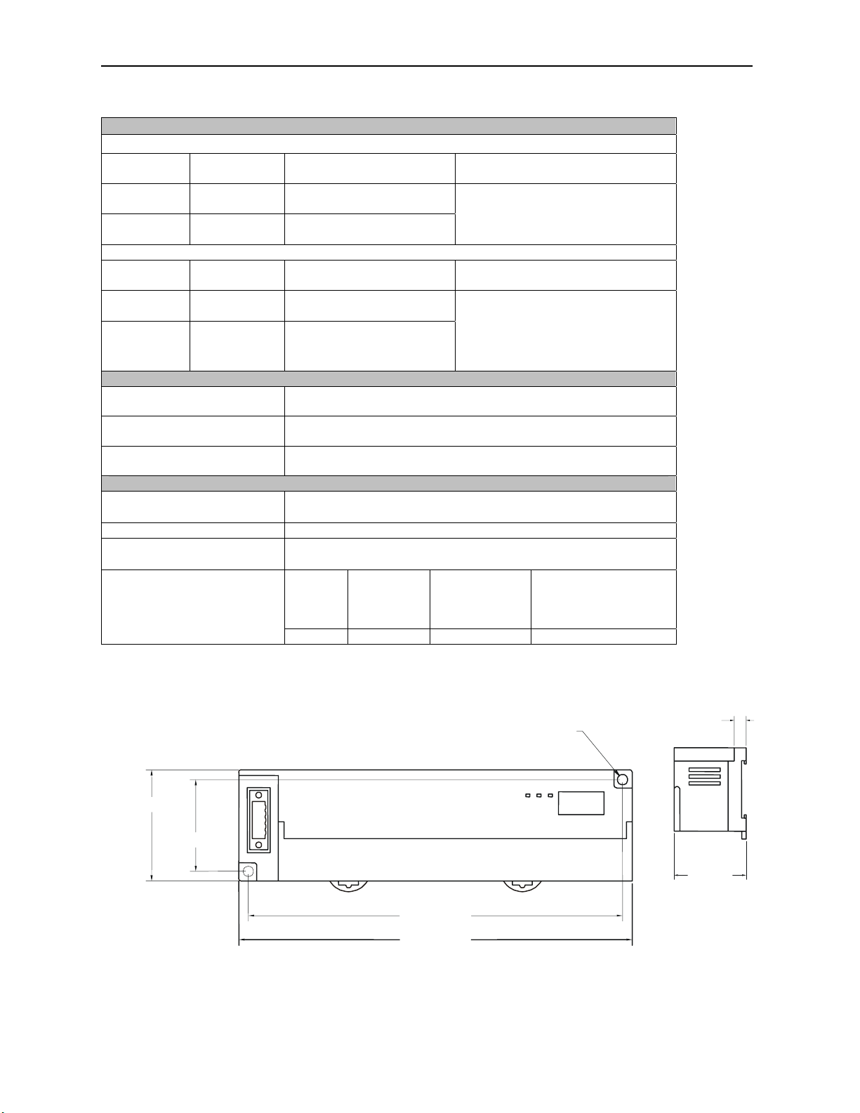
Page 2 07 APR 2006 MIX577
Vibration
Occasional Vibration
Frequency Acceleration Amplitude
10 ≤ f < 57
Hz
57 ≤ f ≤ 150
Hz
Frequency Acceleration Amplitude
10 ≤ f <
57 Hz
57≤ f ≤
150 Hz
Shocks
Maximum shock
acceleration
Duration Time
- 0.075 mm
9.8 m/s2 {1G} -
Continuous Vibration
- 0.035 mm
{0.5G}
2
-
4.9 m/s
10 times in each direction for X,Y,Z
10 times in each direction for X,Y,Z
2
147 m/s
{15G}
11 ms.
Sweep
Count
Sweep
Count
Pulse Wave
Noise Immunity
Square wave impulse noise
Electrostatic Discharge
Radiated electromagnetic
field
Fast Transient
Burst Noise
Severity
2 DIMENSIONS
1.97 [49.9mm]
1.62 [41.1mm]
Half sine wave pulse (3 times in each of X, Y, Z directions)
AC: ± 1,500VDC
DC: ± 900VDC
Voltage: 4kV (contact discharge)
27 – 500MHz, 10V/m
Digital I/Os
Digital I/Os
(Ue ≥24V)
(Ue < 24 V)
Analog I/Os
Communication I/Os
0.18 [4.6mm]
level
Voltage
All power
modules
2 kV 1 kV 0.25 kV
6.61 [167.9mm]
6.95 [176.5mm]
0.31
[7.9mm]
1.87
[47.5mm]
HExx9-With
Removable
Terminal
Page 63
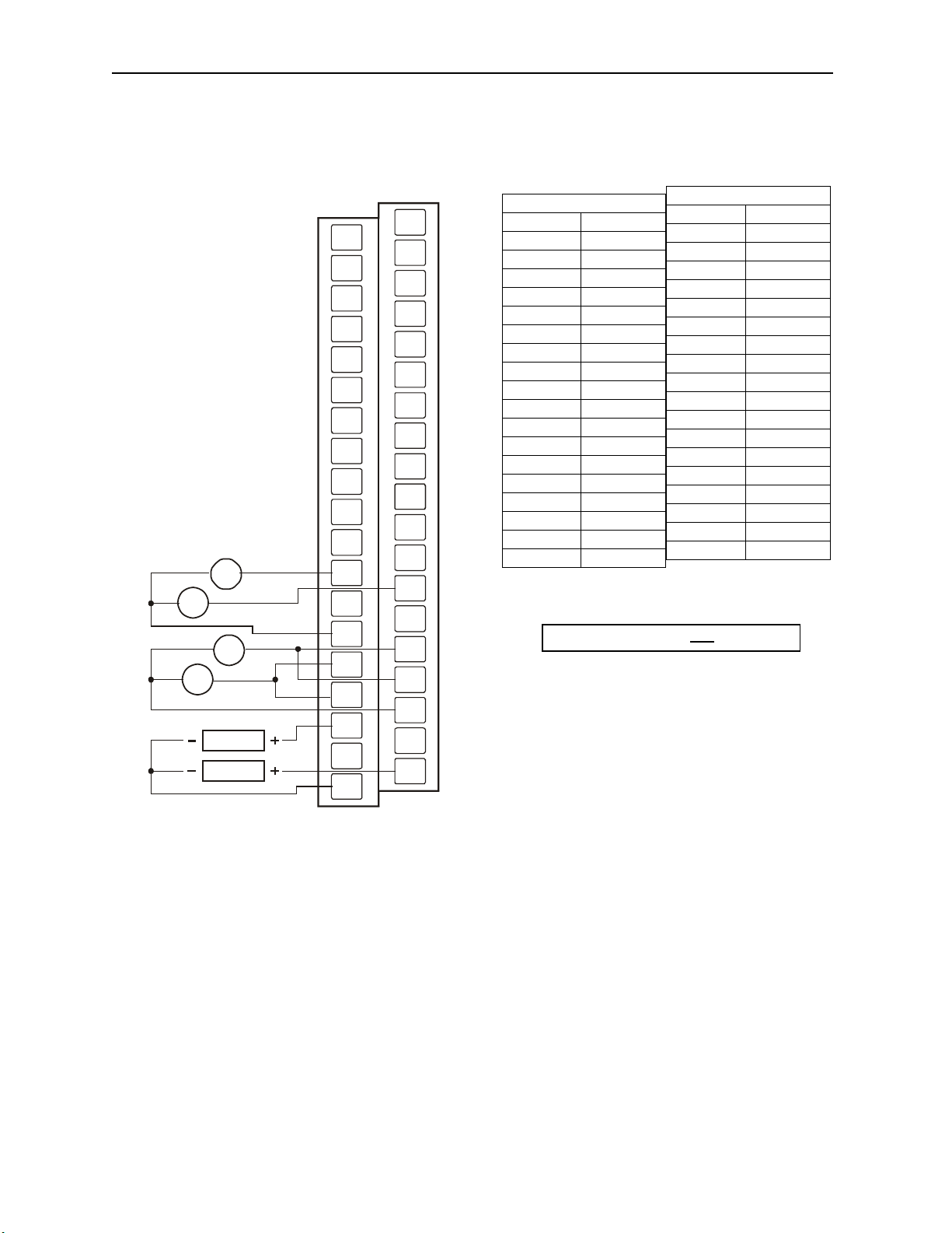
Page 3 07 APR 2006 MIX577
3 WIRING
NC
FT
NC
NC
NC
+/- 10V
+/- 10V
+/-
20mA
+/-
20mA
+/- 10v
LOAD
+/- 20mA
LOAD
NC
NC
NC
NC
NC
NC
I1v
I1i
C
I3v
I3i
Q1v
Q1i
C
NC
FT
FT
NC
NC
NC
NC
NC
NC
NC
NC
C
I2v
I2i
I4v
I4i
C
Q2v
Q2i
MIX577
2 NC
4 FT
6 NC
8 NC
10 NC
12 NC
14 NC
16 NC
18 NC
20 NC
22 NC
24 I1v
26 I1i
28 C
30 I3v
32 I3i
34 Q1v
36 Q1i
38 C
FT: Factory Test, Do Not Connect
006MIX003-R1
C terminals are connected together internally but isolated from bus and power circuits.
MIX577
1 NC
3 FT
5 FT
7 NC
9 NC
11 NC
13 NC
15 NC
17 NC
19 NC
21 NC
23 C
25 I2v
27 I2i
29 I4v
31 I4i
33 C
35 Q2v
37 Q2i
Page 64
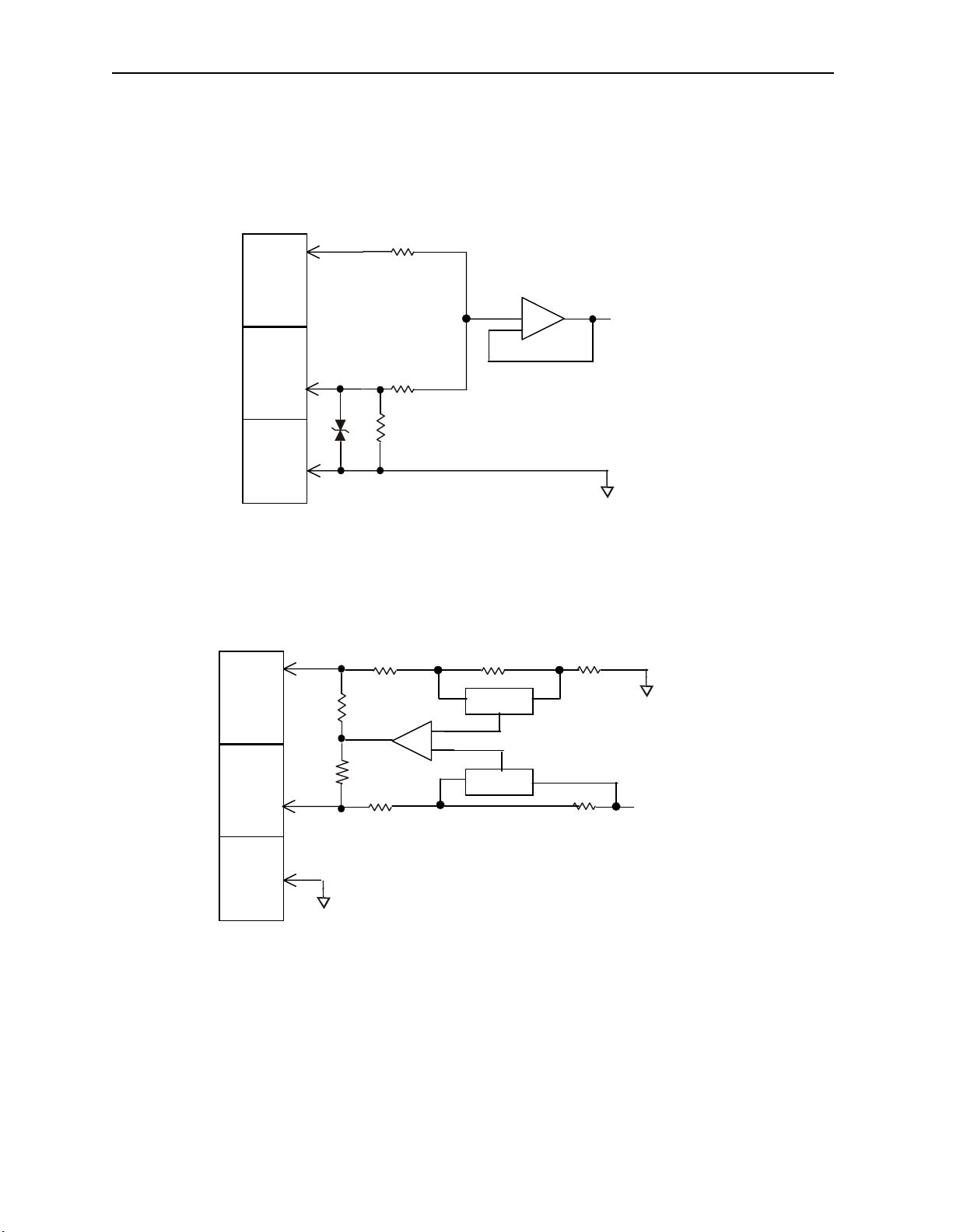
Page 4 07 APR 2006 MIX577
Ω
Ω
_
4 INTERNAL WIRING
I/O Connector
Voltage
Input
Field
Side
Current
Input
Isolated
Common
I/O Connector
Voltage
Output
Field
Side
Current
Output
Isolated
Common
SmartStack Inputs
700K
300K
150Ω
6V
100Ω
Ω
100
SmartStack Outputs
Mode
-
+
Mode
+
To
Controller
<
From
Controller
Page 65
Page 5 07 APR 2006 MIX577
5 CHANNEL MODE, PROGRAMMABLE FILTER, AND OUTPUT DEFAULT
CONFIGURATION
The network supplies configuration information to the HE550MIX577 in the Consumed Directed Digital
Data Words sent to the HE550MIX577. In the first word, the low 12 bits, 1 through 12, are channel mode
bits. A low mode bit selects ±10V and a high mode bit selects ±20mA. The next three bits, 13 through
15, are input digital filter time constant codes and the high bit, 16, is an adaptive filter enable bit. In the
second word, the low 12 bits are channel scale bits. A low scale bit selects ±10V or ±20mA for the
corresponding channel. A high scale bit selects ±5V or 4-20mA. The upper four bits are unused.
Bit Channel
1 AI1
2 AI2
3 AI3
4 AI4
5 Not used
6 Not used
7 Not used
8 Not used
9 AQ1
10 AQ2
11 Not used
12 Not used
Each analog input on the HE550MIX577 has a single pole 345Hz (461uS) cutoff high frequency noise
filter. In addition a second digital filter may be specified in the first configuration word with the following
time constants.
Bit Time Constant
15 14 13
0 0 0 10 milliseconds (Nominal hardware scan rate)
0 0 1 15 milliseconds
0 1 0 35 milliseconds
0 1 1 75 milliseconds
1 0 0 155 milliseconds
1 0 1 315 milliseconds
1 1 0 635 milliseconds
1 1 1 1.275 seconds
This digital filter is useful for applications with significant amounts of random noise. The slower time
constants, while yielding better noise suppression, take a longer time to settle after step changes and are
also sensitive to impulse noise which is treated like Gaussian noise and averaged.
Bit 16 of the first configuration word may be set to specify an adaptive filter algorithm that:
1. Responds much more quickly to large step changes at slower time constants with full filtering of low
level noise.
2. Suppresses impulse noise at the expense of slightly slower response at the shortest time constant
settings. (Approximately 10 additional milliseconds)
Note that actual system response time is network dependent.
Page 66
Page 6 07 APR 2006 MIX577
Bits 9 through 12 of the 5th configuration word control the behavior of the analog outputs when network
communication is lost. The bit to channel correspondence is the same as for the mode and scale bits. If
the corresponding bit is set, the outputs hold the last state. If the corresponding bit is cleared, the outputs
are set to the respective value supplied to the HE550MIX577 in the second four words of the Consumed
Directed Analog Data sent by the OCS. The other bits of the 5th configuration word are unused.
Refer to SmartStix Analog Programming Guide.
6 INPUT AND OUTPUT CONVERSION FACTORS
The following table describes how real-world values are scaled in the controller. For a given physical
voltage or current, the register data value may be calculated by using the conversion factor from the
table. The following formula is used: Data = Voltage or Current / Conversion Factor
Example: The user selects a voltage range of ±10V:
1. The physical voltage is 6 Volts.
2. Using the table, the conversion factor for the voltage range of ±10V is .0003125.
3. To determine the data value, the formula is used: Data = V / Conversion Factor
19200 = 6 VDC / 0.0003125
4. For the 4 to 20mA range, the offset, 4mA, must first be subtracted from the physical output value
before dividing by the scale factor to yield the register data value.
Conversion between Physical Values and Register Values
Selected Range Volts / mA Register Data Conversion Factor
> +5.11 32767
+5.00 32000
±5.00 V
±10.00 V
4..20 mA
±20.00 mA
0.00 0
-5.00 -32000
< -5.11 -32768
> +10.23 32767
+10.00 32000
0.00 0
-10.00 -32000
< -10.23 -32768
< +20.37 32767
+20.00 32000
+4.00 0
-12.00 -32000
> -12.38 -32768
> +20.47 32767
+20.00 32000
0 0
-20.00 -32000
< -20.47 -32768
0.00015625
0.0003125
0.0005
0.0006250
Page 67
Page 7 07 APR 2006 MIX577
7 SETTING ID SWITCHES
CsCAN Network IDs are set using the hexadecimal number system from 01 to FD. The decimal
equivalent is 1-253. Refer to following Conversion Table, which shows the decimal equivalent of
hexadecimal numbers. Set a unique Network ID by inserting a small Phillips screwdriver into the two
identical switches.
Note: The CsCAN Baud Rate for SmartStix I/O is fixed at 125KBaud
SmartStix I/O
9
8
7
A
6
B
5
C
4
D
3
E
2
F
1
0
9
8
7
A
6
B
5
C
4
D
3
E
2
F
1
0
Close-up of Switches
Power and Diagnostic
LEDs
Use this switch to set the
High Digit –has an x16
multiplier.
MS NSPWR
Use this switch to set
the Low Digit – has an
x1 multiplier.
LO (x1) HI (x16)
9
8
7
6
5
4
3
2
1
9
8
A
7
A
6
B
B
5
C
C
4
D
D
3
E
E
2
F
0
F
1
0
Page 68
Page 8 07 APR 2006 MIX577
Decimal (Dec) to Hexadecimal (Hex) Conversion
Dec Hex Dec Hex Dec Hex Dec Dec Hex
HI LO HI LO HI LO HI LO HI LO
54 3 6 108 6 C
1 0 1 55 3 7 109 6 D
2 0 2 56 3 8 110 6 E
3 0 3 57 3 9 111 6 F
4 0 4 58 3 A 112 7 0
5 0 5 59 3 B 113 7 1
6 0 6 60 3 C 114 7 2
7 0 7 61 3 D 115 7 3
8 0 8 62 3 E 116 7 4
9 0 9 63 3 F 117 7 5
10 0 A 64 4 0 118 7 6
11 0 B 65 4 1 119 7 7
12 0 C 66 4 2 120 7 8
13 0 D 67 4 3 121 7 9
14 0 E 68 4 4 122 7 A
15 0 F 69 4 5 123 7 B
16 1 0 70 4 6 124 7 C
17 1 1 71 4 7 125 7 D
18 1 2 72 4 8 126 7 E
19 1 3 73 4 9 127 7 F
20 1 4 74 4 A 128 8 0
21 1 5 75 4 B 129 8 1
22 1 6 76 4 C 130 8 2
23 1 7 77 4 D 131 8 3
24 1 8 78 4 E 132 8 4
25 1 9 79 4 F 133 8 5
26 1 A 80 5 0 134 8 6
27 1 B 81 5 1 135 8 7
28 1 C 82 5 2 136 8 8
29 1 D 83 5 3 137 8 9
30 1 E 84 5 4 138 8 A
31 1 F 85 5 5 139 8 B
32 2 0 86 5 6 140 8 C
33 2 1 87 5 7 141 8 D
34 2 2 88 5 8 142 8 E
35 2 3 89 5 9 143 8 F
36 2 4 90 5 A 144 9 0
37 2 5 91 5 B 145 9 1
38 2 6 92 5 C 146 9 2
39 2 7 93 5 D 147 9 3
40 2 8 94 5 E 148 9 4
41 2 9 95 5 F 149 9 5
42 2 A 96 6 0 150 9 6
43 2 B 97 6 1 151 9 7
44 2 C 98 6 2 152 9 8
45 2 D 99 6 3 153 9 9
46 2 E 100 6 4 154 9 A
47 2 F 101 6 5 155 9 B
48 3 0 102 6 6 156 9 C
49 3 1 103 6 7 157 9 D
50 3 2 104 6 8 158 9 E
51 3 3 105 6 9 159 9 F
52 3 4 106 6 A 160 A 0
53 3 5 107 6 B 161 A 1
162
163
164
165
166
167
168
169
170
171
172
173
174
175
176
177
178
179
180
181
182
183
184
185
186
187
188
189
190
191
192
193
194
195
196
197
198
199
200
201
202
203
204
205
206
207
208
209
210
211
212
213
214
215
A 2
A 3
A 4
A 5
A 6
A 7
A 8
A 9
A A
A B
A C
A D
A E
A F
B 0
B 1
B 2
B 3
B 4
B 5
B 6
B 7
B 8
B 9
B A
B B
B C
B D
B E
B F
C 0
C 1
C 2
C 3
C 4
C 5
C 6
C 7
C 8
C 9
C A
C B
C C
C D
C E
C F
D 0
D 1
D 2
D 3
D 4
D 5
D 6
D 7
216
217
218
219
220
221
222
223
224
225
226
227
228
229
230
231
232
233
234
235
236
237
238
239
240
241
242
243
244
245
246
247
248
249
250
251
252
253
D 8
D 9
D A
D B
D C
D D
D E
D F
E 0
E 1
E 2
E 3
E 4
E 5
E 6
E 7
E 8
E 9
E A
E B
E C
E D
E E
E F
F 0
F 1
F 2
F 3
F 4
F 5
F 6
F 7
F 8
F 9
F A
F B
F C
F D
Page 69
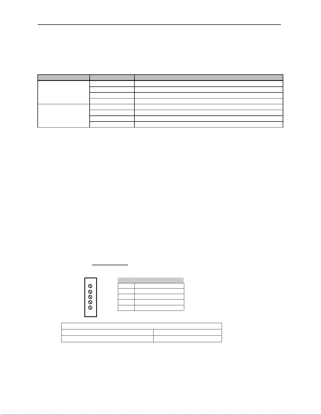
Page 9 07 APR 2006 MIX577
8 LEDS
SmartStix I/O Modules provide diagnostic and status LED indicators.
a. Diagnostic LED Indicators
Diagnostic LED State Meaning
Solid Red Initializing
MS
(Module Status)
NS
(Network Status)
Blinking Red I/O test failed, internal hardware fault
Blinking Green Module is in power-up state *
Solid Green Module is running normally
Solid Red Network Ack or Dup ID test failed **
Blinking Red Network ID test failed: ID not in the range of 1..253
Blinking Green Life Expectancy timeout, outputs are in default state ***
Solid Green Network is running normally
* If a blinking green Module Status persists for more than a few seconds the module has not received the
expected configuration from the OCS. This may be due to no Network I/O configuration created in
Cscape, not having downloaded the Network I/O configuration to the master OCS, an unpowered master
OCS, or the wrong Network ID number set on the module’s rotary switches.
** Network Ack means that no other node is active on the network. Dup ID test failed means that
another node with the same ID switch setting is already on the network.
*** Life Expectancy timeout means that the module has not received a periodic message from the master
OCS in the time specified in either the Life Expectancy directed data message or the Comm timeout of
the Network I/O Configuration window in Cscape.
b. Status LED Indicators
The Power Status LED illuminates Red when power is applied to the module. There are I/O Status LED
indicators for each of the Digital I/O points, which illuminate Red when an I/O point is ON.
9 NETWORK CABLE
For detailed wiring information, refer to the applicable hardware manual listed in this datasheet under
Installation/Safety. A handy checklist
minimum clearances.
Pin Description
RED 1 V+
WHT 2 CAN_H
SHD 3 Shield
BLU 4 CAN_L
BLK 5 V-
Thick: (Max Distance = 500m) Belden 3082A
Thin: (Max Distance = 100m) Belden 3084A
is provided that covers panel box layout requirements and
Recommended Cable
Page 70
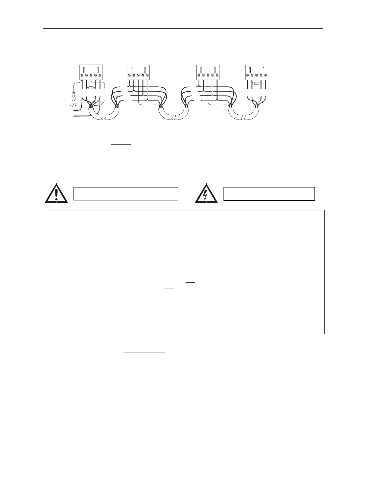
Page 10 07 APR 2006 MIX577
CN_LV-SHIELD121
V+
CN_H
CN_LV-SHIELD
V+
CN_H
CN_LV-SHIELD
V+
CN_H
CN_LV-SHIELD
V+
CN_H
Ω
BLU
BLK
RED
RED
WHT
-
+
12-25VDC
BLK
BLK
BLU
BLU
WHT
SHIELD
WHT
RED
RED
SHIELD
BLK
BLK
BLU
BLU
WHT
WHT
RED
RED
SHIELD
BLK
Ω
121
BLU
001CAN002
WHT
RED
CAN Wiring
Note: 12 - 24VDC must be supplied to the network.
10 INSTALLATION / SAFETY
When found on the product, the following symbols specify:
WARNING: To avoid the risk of electric shock or burns, always connect the safety (or earth)
ground before making any other connections.
WARNING: To reduce the risk of fire, electrical shock, or physical injury it is strongly
recommended to fuse the voltage measurement inputs. Be sure to locate fuses as close to the
source as possible.
WARNING: Replace fuse with the same type and rating to provide protection against risk of
fire and shock hazards.
WARNING: In the event of repeated failure, do not replace the fuse again as a repeated failure
indicates a defective condition that will not
WARNING: Only qualified electrical personnel familiar with the construction and operation of
this equipment and the hazards involved should install, adjust, operate, or service this
equipment. Read and understand this manual and other applicable manuals in their entirety
before proceeding. Failure to observe this precaution could result in severe bodily injury or
loss of life.
For detailed installation and a handy checklist
clearances, refer to the hardware manual of the controller you are using. (See the Additional
References section in this document.)
• All applicable codes and standards need to be followed in the installation of this product.
• For I/O wiring (discrete), use the following wire type or equivalent: Belden 8441 or equivalent.
Warning: Consult user documentation.
that covers panel box layout requirements and minimum
Warning: Electrical Shock Hazard.
clear by replacing the fuse.
Page 71
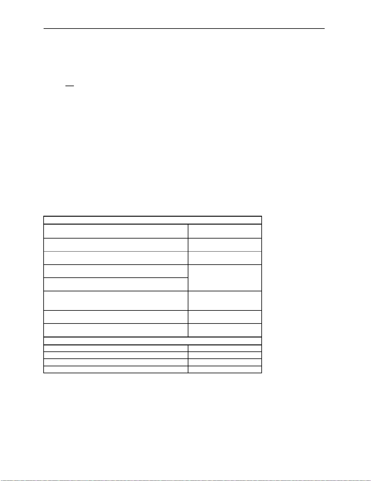
Page 11 07 APR 2006 MIX577
Adhere to the following safety precautions whenever any type of connection is made to the module.
• Connect the green safety (earth) ground first before making any other connections.
• When connecting to electric circuits or pulse-initiating equipment, open their related breakers. Do
make connections to live power lines.
not
• Make connections to the module first; then connect to the circuit to be monitored.
• Route power wires in a safe manner in accordance with good practice and local codes.
• Wear proper personal protective equipment including safety glasses and insulated gloves when
making connections to power circuits.
• Ensure hands, shoes, and floor are dry before making any connection to a power line.
• Make sure the unit is turned OFF before making connection to terminals. Make sure all circuits
are de-energized before making connections.
• Before each use, inspect all cables for breaks or cracks in the insulation. Replace immediately if
defective.
11 ADDITIONAL REFERENCES
The following table indicates the hardware manual numbers for the controller you are using. Hardware
manuals contain detailed installation, configuration and other pertinent information. See the Technical
Support section in this document for the web site address to download references and obtain revised
editions.
Additional References
Controller Manual Number
QX Series Hardware
e.g. HEQX451, HEQX551, HEQX651
NX Series Hardware
e.g. HENX220, HENX221, HENX250, HENX251
Operator Control Station Hardware (OCS, OCX)
e.g., OCS1XX / 2XX; Graphic QCS250
Remote Control Station Hardware
RCS (except RCS116), RCX (e.g., RCS210, RCS250)
Color Touch QX Hardware
e.g., OCS300, OCS 301, OCS 350, OCS 351
e.g., OCS 451, OCS 551, OCS 651
LX Series Hardware
e.g., LX-280 / LX-300; RCS116
MiniQX / MiniRCS / MiniOCX / MiniRCX Hardware
e.g., HE500QXxxx
MAN0798
MAN0781
MAN0227
MAN0465
MAN0755
MAN0305
Other Useful References
CAN Networks MAN0799
Cscape Programming and Reference MAN0313
DeviceNet™ Implementation
Wiring Accessories and Spare Parts Manual MAN0347
SUP0326
Page 72

Page 12 07 APR 2006 MIX577
12 TECHNICAL SUPPORT
For assistance and manual updates, contact Technical Support at the following locations:
North America:
(317) 916-4274
www.heapg.com
email: [email protected]
Europe:
(+) 353-21-4321-266
www.horner-apg.com
email: [email protected]
 Loading...