

Page 1

Technical Specifications *
Accuracy: < 2% of FS range under constant conditions
Analysis: 0-1%, 0-5%, 0-10%, 0-25% FS ranges; auto-ranging or
fixed single range
Application: Oxygen analysis in inert, hydrocarbon, helium, hydrogen,
mixed and acid (CO2) gas streams
Area Classification: General purpose
Calibration: Max interval—3 months. Air calibrate with clean source
of certified span gas, compressed, or ambient (20.9%
O2) air on 0-25% range.
Compensation: Temperature
Connections: 1/8" compression tube fittings
Controls: Water resistant keypad; menu driven range selection,
calibration and system functions
Display: Graphical LCD 2.75” x 1.375”; resolution 0.001%; dis-
plays real time ambient temperature and pressure
Enclosure: Fiberglass NEMA 4X, 6.75 x 8.375 x 4.25”, 8 lbs.
Flow Sensitivity: Not flow sensitive, 1-2 SCFH recommended
Linearity: ±1% of full scale
Pressure: Inlet - regulate to 5-30 psig to deliver 1-2 SCFH flow;
vent - atmospheric
GPR-2500 N
Oxygen Transmitter
2 Wire Loop Powered O2 Transmitter
with Optional Sample Systems
Power: 18-24 VDC
Response Time: 90% of final reading in 13 seconds
Sample System: None
Sensitivity: < 0.5% of FS range
Sensor Model: GPR-11-32-4 for non-acid (CO2) gas streams
XLT-11-24-4 for gases containing > 0.5% CO2
Sensor Life: GPR-11-32-4 32 months in air at 25ºC and 1 atm
XLT-11-24-4 24 months in air at 25ºC and 1 atm
Signal Output: 4-20mA non-isolated
Operating Range: 5ºC to 45ºC (GPR sensor), -10º to 45ºC (XLT sensor)
Warranty: 12 months analyzer; 12 months sensor
Wetted Parts: Stainless steel
Optional Equipment
Sample conditioning system - Contact factory.
* Subject to change without notice
Advanced Sensor Technology
Longer Life with No Maintenance
Excellent Compatibility in 0-100% CO
Extended Operating Temperature –10⁰C
18-24 VDC Loop Power
4-20 mA Signal Output
Sensitivity 0.5% Full Scale
4 Ranges Standard
Auto Ranging or Single Fixed
Stainless Steel Wetted Parts
ISO 9001:2008 Certified
INTERTEK Certificate No. 485
2
2855 Metropolitan Place, Pomona, CA 91767 USA ♦ Tel: 909-392-6900, Fax: 909-392-3665, www.aii1.com, e-mail: [email protected] Rev 10/15
Page 2

Advanced Instruments Inc.
GPR-2500 N
% Oxygen Transmitter
Owner's Manual
Revised July 2014
2855 Metropolitan Place, Pomona, California 91767 USA ♦ Tel: 909-392-6900, Fax: 909-392-3665, e-mail:
[email protected]
Page 3

Advanced Instruments Inc.
Introduction
1
Quality Control Certification
2 Safety
3 Features & Specificatio ns
4
Operation
5 Maintenance
6
Spare Parts
7 Troubleshooting
8
Warranty
9 Material Safety Data Sheets
10
Drawings
A/R
Explosion Proofing Electrical Connections
Appendix
A
Correlating readings – LCD display to 4-20mA signal output
Appendix
B
H2S Scrubber, Sample System, Media MSDS
Appendix
F
Maintenance H2S Scrubber & Coalescing Filter
Appendix
G
Table of Contents
The appendices referenced above are an integral part of the documentation, installation and maintenance of this
analyzer to comply with all applicable directives. It is important that users review these documents before proceeding.
2
Page 4
Advanced Instruments Inc.
1. Introduction
Your new oxygen transmitter i ncorporates an advanced electrochemical sensor specific to oxygen along with state-ofthe-art digital electronics designed to give you years of reliable precise oxygen measurements in a variety of industrial
oxygen applications. More importantly, it has been constructed as intrinsically safe in accordance with ATEX Directives
94/9/CE for use in hazard ou s areas in zone 1 Group C and D.
Analytical Industries, Inc.
dba Advanced Instruments Inc.
2855 Metropolitan Place, Pomona, CA 91767 USA
GPR-1500/2500 N
0080
Serial No.:
Year of Manufacture:
INERIS 08ATEX0036
II 2 G
Ex ia IIB T4 Gb
T
WARNING: POTENTIAL ELECTROSTATIC CHARGING HAZARD – SEE INSTRUCTIONS
The design also meets NEC intrinsic safety standards for use in Class 1, Division 1, Group C, D hazardous areas.
Please refer to Appendix A for information on making electrical connections that maintain the desired level of
protection.
To obtain maximum performance from your new oxygen transmitter, please read and follow the guidelines provided in
this Owner’s Manual.
Every effort has been made to select the most reliable state of the art materials and components, to design the
transmitter for superior performance and minimal cost of ownership. This transmitter was tested thoroughly by the
manufacturer prior to shipment for best performance.
However, modern electronic devices do require service from time to time. The warranty included herein plus a staff of
trained professional technicians to quickly service your transmitter is your assurance that we stand behind every
transmitter sold.
The serial number of this transmitter may be found on the inside the transmitter enclosure. You should note the serial
number in the space provided and retains this Owner’s Manual as a permanent record of your purchase, for future
reference and for warranty considerations.
Serial Number: _______________________
Advanced Instruments Inc. appreciates your business and pledges to make every effort to maintain the highest
possible quality standards with respect to product design, manufacturing and service.
-20⁰C to +50⁰C
amb
3
Page 5
Advanced Instruments Inc.
3. General Safety & Installation
This section summarizes the essential precautions applicable to the GPR-1500/2500 N Oxygen Transmitter. Additional
precautions specific to individual transmitter are contained in the following sections of this manual. To operate the
transmitter safely and obtain maximum performance follow the basic guidelines outlined in this Owner’s Manual.
Caution: This symbol is used throughout the Owner’s Manual to Caution and alert the user to
recommended safety and/or operating guidelines.
Warning: This symbol is used throughout the Owner’s Manual to Warn and alert the user of the presence
of electrostatic discharge.
Danger: This symbol is used throughout the Owner’s Manual to identify sources of immediate Danger
such as the presence of hazardous voltages.
Read Instructions: Before operating the transmitter read the instructions.
Retain Instructions: The safety precautions and operating instructions found in the Owner’s Manual should be
retained for future reference.
Heed Warnings: Follow all warnings on the transmitter, accessories (if any) and in this Owner’s Manual.
Follow Instructions: Observe all precautions and operating instructions. Failure to do so may result in personal injury
or damage to the transmitter.
Analyzer label
4
Page 6

Advanced Instruments Inc.
Maintenance
Serviceability: Except for replacing the oxygen sensor, there are no parts inside the transmitter for the operator to
service.
Only trained personnel with the authorization of their supervisor should conduct maintenance.
Oxygen Sensor: DO NOT open the sensor. The sensor contains a corrosive liquid electrolyte that could be harmful if
touched or ingested, refer to the Material Safety Data Sheet contained in the Owner’s Manual appendix. Avoid contact
with any liquid or crystal type powder in or around the sensor or sensor housing, as either could be a form of
electrolyte. Leaking sensors should be disposed of in accordance with local regulations.
Troubleshooting: Consult the guideli nes in Sect ion 8 for advice on the com mon oper atin g err ors before concluding
that your transmitter is faulty. Do not attempt to service the transmitter beyond those means described in this Owner’s
Manual.
Do not attempt to make repairs by yourself as this will void the warranty as per Section 10 and may result in electrical
shock, injury or damage. All other servicing should be referred to qualified service personnel.
Cleaning: The transmitter should be cleaned only as recommended by the manufacturer. Wipe off dust and dirt from
the outside of the unit with a soft damp cloth then dry immediately. Do not use solvents or chemicals.
Nonuse Periods: If the transmitter is equipped with a POWER switch advance the switch to the OFF position and
disconnect the power when the transmitter is left unused for a long period of time.
Installation
This analyzer has been constructed in compliance with
EN 60079-0 : 2007
EN 60079-11 : 2012
It must be installed in accor dance with
EN 60079-14
Gas Sample Stream: Ensur e the gas strea m com pos iti on of the appli cat ion is con si ste nt w ith the speci fic atio ns and if
in doubt, review the application and consult the factory before ini tiat ing the ins tallation. Note: In natural gas
applications such as extraction and transmission, a low voltage current is applied to the pipeline itself to inhibit
corrosion of the pipeline. As a result, electronic devices connected to the pipeline can be affected unless they are
adequately grounded.
Contaminant Gases: A gas scrubber and flow indicator with integral metering valve are required upstream of the
analyzer to remove any interfering gases such as oxides of sulfur and nitrogen or hydrogen sulfide that can interfere
with measurement and cause reduction in the expected life of the sensor. Consult the factory for recommendations
concerning the proper selection and installation of components.
Expected Sensor Life: With reference to the publi sh spe cif i cati on loca ted at the last page of this manual, the expected
life of all oxygen sensors is predicated on oxygen concentration in ambient air, temperature (77°F/25°C) and pressure
(1 atmosphere) in “normal” applications. Deviations from standard conditions will affect the life of the sensor. As a rule
of thumb sensor life is inversely proportional to changes in the pressure and temperature.
Accuracy & Calibration: Refer to section 5 Operation.
Operating Temperature: The sample must be sufficiently cooled before it enters the analyzer and any optional
components. A coiled 10 foot length of ¼” stainless steel tubing is sufficient for cooling sample gases as high as 1,800
ºF to ambient. The recommended operating temperature is below 35 ºC. However, the analyzer may be operated at
temperature up to 45 ºC on an intermittent basis but the user is expected to accept a reduction in expected sensor life –
as a rule of thumb, for every degree ºC increase in temperature (above 25 ºC), the sensor life is reduced by
approximately 2.5%.
Heat: Situate and store the analyzer away from direct sources of heat.
Liquid and Object Entry: The analyzer should not be immersed in any liquid. Care should be taken so that
liquids are not spilled into and objects do not fall into the inside of the analyzer.
5
Page 7

Advanced Instruments Inc.
Handling: Do not use force when using the switches, knobs or other mechanical components. Before moving your
analyzer be sure to disconnect the wiring/power cord and any cables connected to the output terminals of the analyzer.
Sample Pressure and Flow
All electrochemical oxygen sensors respond to partial pressure changes in oxygen. The sensors are equally capable of
analyzing the oxygen content of a flowing sample gas stream or monitoring the oxygen concentration in ambient air
(such as a confined space in a control room or an open area around a landfill or bio-pond). The follow ing is appl ic able
to analyzers equipped with fuel cell type oxygen sensors.
Analyzers designed for in-situ ambient or area monitoring has no real sample inlet and vent. The sensor is exposed
directly to the sample gas and it is intended to operate at atmospheric pressure. The analyzer has a built-in pressur e
sensor and the sensor output is automatically compensated for any atmospheric pressure changes.
Inlet Pressure: For the analyzers designed to measure oxygen in a flowing gas stream, the inlet sample pressure
must be regulated between 5-30 psig. Although the rating of the SS tubing and tube fittings/valves itself is consi derably
higher (more than 100 psig), a sample pressure of 5-30 psig is recommended for ease of control of sample flow.
The analyzer equipped with a sample system has designated SAMPLE and VENT ports. Connect SAMPLE gas to
SAMPLE and the vent to the VENT ports only.
Caution: If the analyzer is equipped with an optional H2S scrubber, sample inlet pressure must not ex ceed
30 psig.
Outlet Pressure: In applications where sample pressure is positive, the sample must be vented to an exhaust
pipe at a pressure less than the inlet pressure so that the sample gas can flow through the sensor housing. Ideally, the
sample must be vented to atmospheric pressure.
Note: The sensor may be used at a slight positive pressure (e.g., when sample is vented to a common exhaust where
the pressure might be higher than 1 atmosphere). However, the pressure at the sensor must be maintained at all times
including during the span calibration. This may be accom pli s hed by using a back-pressure regulator at vent line of the
analyzer. Caution: A sudden change in pressure at the sensor may result in the sensor electrolyte leakage.
Flow rates of 1-2 SCFH cause no appreciable change in the oxygen reading. However, flow rates above 5 SCFH may
generate a slight backpressure on the sensor resulting in erroneous oxygen readings.
Caution: Do not place your finger over the vent (it pressurizes the sensor) to test the flow indicator when
gas is flowing to the sensor. Removing your finger (the restriction) generates a vacuum on the sensor and
may damage the sensor (voiding the sensor warranty).
Application Pressure - Positive: A flow indicator with integral metering valve positioned upstream of the
sensor is recommended for controlling the sample flow rate between 1-5 SCFH. If a separate flow control valve and a
flow indicator is used, position flow control valve upstream of the sensor and position a flow indicator downstream of
the sensor. If necessary, a pressure regulator upstream of the flow control valve should be used to regulate the inlet
pressure between 5-30 psig.
Caution: If the analyzer is equipped with a H2S scrubber as part of an optional sample conditioning system, inlet
pressure must not exceed 30 psig.
Application Pressure - Atmospheric or Slightly Negative: For % oxygen measurements, an
optional external sample pump may be used upstream of the sensor to pu sh the sample acr oss the sen sor and out to
atmosphere. For PPM oxygen measurements, an optional external sampling pump should be positioned downstream
of the sensor to draw the sample from the process, by the sensor and out to atmosphere. A flow meter is generally not
necessary to obtain the recommended flow rate with most sampling pumps. However, if the sample pump can
pull/push more than 5 SCFH, a flow control must be used to control the sample flow. The flow control valve must be
positioned in such a way that it does not generate any vacuum on the sensor.
Caution: If the analyzer is equipped with a flow indicator with integral metering valve or a metering flow
control valve upstream of the sensor and the pump is installed downstream of sensor- open the meter ing
valve completely before turning the pump ON to avoid drawing a vacuum on the sensor and placing an
undue burden on the pump.
6
Page 8

Advanced Instruments Inc.
If pump loading is a consideration, a second throttle valve on the pump’s inlet side may be necessary to provide a
bypass path so the sample flow rate is within the above parameters.
Moisture & Particulates: Installation of a suitable coalescing or particulate filter is required to remove
condensation, moisture and/or particulates from the sample gas to prevent erroneous analysis readings and damage to
the sensor or other optional components. Moisture and/or particulates do not necessarily damage the sensor. However,
collection of moisture/part icu la te on the sensing surface can block or inhibit the diffusion of sample gas into the sensor
resulting in a reduction of sensor signal output – and the appearance of a sensor failure. Consult the factory for
recommendations concerning the pro per sel ect ion and in stal l ation of optional components.
Moisture and/or particulates generally can be removed from the sensor by opening the sensor housing and either
blowing on the sensing surfa c e or gently wiping or brushing the sensing surface with damp cloth. Caution: Minimize
the exposure of PPM sensors to air during this cleaning process. Air calibration followed by purging with zero or a gas
with a low PPM oxygen concentration is recommended after the cleaning process is completed.
Mounting: The analyzer is approved for indoor as well as outdoor use. However, avoid mounting in an area where
direct sun might heat up the analyzer beyond the recommended operating temperature range. If possible, install a
small hood over the analyzer for rain water drain and to prevent over-heating of analyzer..
Gas Connections: The Inlet and outlet vent gas lines require 1/8” or ¼” stainless steel compression type tube
fittings. The sample inlet tubing must be metallic, preferably SS. The sample vent line may be of SS or hard plastic
tubing with low gas permeability.
Power: Supply power to the analyzer only as rated by the specification or markings on the analyzer enclosure. The
GPR-2500 N is a two wire loop powered analyzer. To comply with the ATEX Directives 94/9/CE, power to the
transmitter must be provided via an approved intrinsic safety barrier MTL 7706+ or equivalent.
WARNING: TRANSMITTER RATING FOR USE IN HAZARDOUS AREA WILL VOID WITHOUT THE USE OF
INTRINSIC SAFETY BARRIER
The input power must be between 24-28 VDC. The wiring that connects the analyzer to the power source should be
installed in accordance with recognized electrical standards. Ensure that the analyzer case is properly grounded and
meets the requirements for area classification where the analyzer is installed. Never yank wiring to remove it from a
terminal connection.
The two wire loop powered analyzers consume no more than 0.68 Watts of power.
7
Page 9

4. Features & Specifications
Advanced Instruments Inc.
8
Page 10
Advanced Instruments Inc.
5. Operation
Principle of Operation
The GPR-2500 N Oxygen Transmitter incorporates a variety of advanced galvanic fuel cell type oxygen sensors. These
sensors are very specific to oxygen and generate an electrical signal proportional to the amount of oxygen present in a
gas stream. The selection of a particular type of sensor depends on the composition of the sample gas stream. Consult
the factory for recommendation.
The signal processing electronics and sensor are housed in a general purpose NEMA 4X rated enclosure. The
terminals for incoming power, signal output and intrinsic safety barriers are mounted on a PCB housed in an explosion
proof enclosure.
The intrinsic safety barriers MTL7706+ or equivalent, limits the amount of power that flows to and from the signal
processing electronics to a safe level effectively preventing an explosive condition. The analyzer design conforms to
the ATEX Directive 94/9/CE for equipment as intrinsically safe and has been approved by an independent body: EC
Type Examination Certificate: INERIS 08ATEX0036
The analyzer carries the following area classification
II 2 G,
Ex ia IIB T4 Gb
T
The GPR-2500 N also meets the intrinsic safety standards required for use in Class 1, Division 1, Group C, D
hazardous areas.
-20⁰C to +50⁰C
amb
WARNING: POTENTIAL ELECTROSTATIC CHARGING HA ZARD-SEE INSTRUCTION
9
Page 11

Advanced Instruments Inc.
Advanced Galvanic Sensor Technology
All galvanic type sensors function on the same principle and are specific to oxygen. They measure the partial pressure
of oxygen from low PPM to 100% levels in inert gases, gaseous hydrocarbons, helium, hydrogen and mixed gases
Oxygen, the fuel for this electrochemical transducer, diffusing into the sensor, reacts electrochemically at the sensing
electrode to produce an electrical current output proportional to the oxygen concentration in the gas phase. The
sensor’s signal output is linear over all measuring ranges and remains virtually constant over its useful life. The sensor
requires no maintenance and is easily and safely replaced at the end of its useful life.
Proprietary advancements in design and chemistry add significant advantages to this extremely versatile oxygen
sensing technology. Sensors for low % analysis recover from air to low % levels in seconds, exhibit longer life and
reliable quality. The expected life of our new generation of percentage range sensors now range from 32 months to ten
years with faster response times and greater stability. Another significant development involves expanding the
operating temperature range for percentage range sensors from -20°C to 50°C. Contact factory for more specific
information about your application.
Electronics
The signal generated by the sensor is processed by state of the art low power micro-proce ssor ba sed digital circuitry.
The first stage amplifies the signal. The second stage eliminates the low frequency noise. The third stage employs a
high frequency filter and compensates for signal output variations caused by ambient temperature changes. The result
is a very stable signal. Sample oxygen is analyzed very accurately. Response time of 90% of full scale is less than 10
seconds (actual experience may vary due to the integrity of sample line connections, dead volume and flow rate
selected) on all ranges under ambient monitor ing con diti ons. Sensitivity is typically 0.5% of full scale of the low range.
Oxygen readings may be recorded by an external device via the 4-20 mA or 1-5V signal output.
10
Page 12
Advanced Instruments Inc.
Sample System:
The standard GPR-2500 N is supplied without a sample conditioning system thereby giving users the option of adding
their own or purchasing a factory designed sample conditioning system, see section 2 QC Certification for optional
equipment ordered. Whatever the choi ce, the sa mpl e must b e proper ly conditioned before introducing it to the sensor
to ensure an accurate measurement.
The GPR-2500 N is generally supplied with a minimum of a sample flow control valve and a flow meter. Users
interested in adding their own sample conditioning system should consult the factory. Advanced Instruments Inc. offers
a full range of sample handling, conditioning and expertise to meet your application requirements. Contact us at 909392-6900 or e-mail us at
Calibration & Accuracy Overview
Single Point Calibration: A s prev ious ly
described the galvanic type oxygen sensor
generates an electrical current proportional to the
oxygen concentration in the sample gas. In the
absence of oxygen the sensor exhibits an
absolute zero, e.g. the sensor does not
generate a current output in the absence of
oxygen. Given these linearity and absolute zero
properties, single point calibration is possible.
Pressure: Because sensors are sensitive to
partial pressure of oxygen in the sample gas, their
output is a function of the number of molecules of
oxygen or percentage 'per unit volume'.
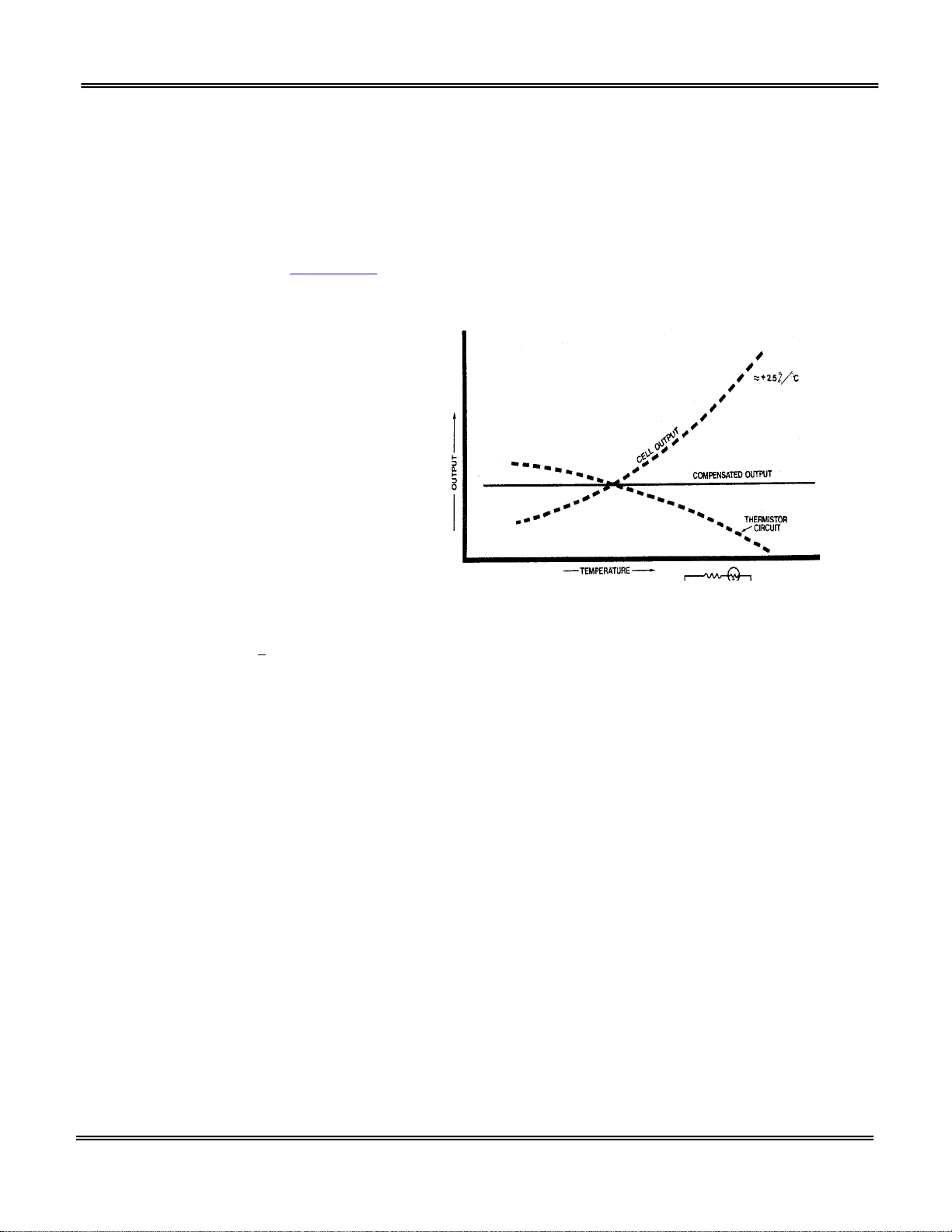
Temperature: The rate at which oxygen
molecules diffuse into the sensor is controlled by a
Teflon membrane otherwise known as an 'oxygen diffusion limiting barrier' and all diffusion processes are temperature
sensitive, the fact the sensor's electrical output will vary with temperature is normal. This variation is relatively constant
(2.5% per ºC). A temperature compensation circuit employing a thermistor and a network of resisters offsets this effect
with an accuracy of +
signal output remains virtually independent of ambient temperature. There is extremely low error in measurement if the
calibration and sampling are performed at similar temperatures (within +/- 5 ºC. Conversely, a temperature variation of
10 ºC may produce an error of >2% of full scale .
Accuracy: In light of the above parameters, the overall accuracy of an analyzer is affected by two types of errors: 1)
'percent of reading errors', illustrated by Graph A below and 2) 'percent of full scale errors', illustrated by Graph B, such
as1-2% errors in readout and calibration devices. Other errors are 'spanned out' during calibration, especially when
analyzer is calibrated close to the top end of the measuring range.
5% or better over a wide operating temperature range e.g., 5-45 oC can be obtained thus the
the
11
Page 13
Advanced Instruments Inc.
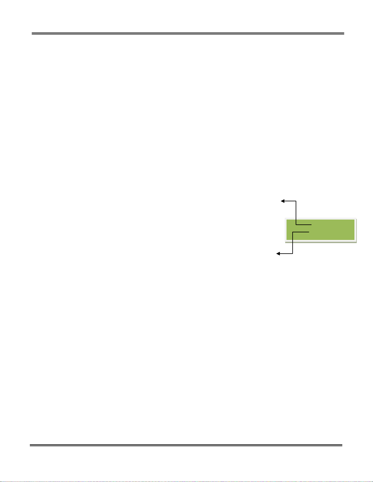
Sample In and
Mounting the Transmitter
The GPR-2500 N is housed in a Fiber Glass NEMA4X rated enclosure. This configuration is designed to be mounted
directly to any flat vertical surface, wall or bulkhead plate with four (4) of the appropriate size screws. To facilitate
servicing the interior of the transmitters, position it approximately 5 feet off ground level.
Sample Out
To mount the transmitter, remove the four screws from the front door of the transmitter. Lift the door up. Use four
screws/anchors and install the transmitter on a smooth vertical flat surface/wall.
Caution: Do not remove or discard the gaskets from the enclosure. Failure to reinstall the gaskets will void
the NEMA 4 rating and the im muni ty to RFI/EMI.
The transmitters design provides immunity from RFI /EMI by maintaining a good conductive contact
between the two halves of the enclosures via a conductive gasket (th e smal ler enc los ure c ont ai nin g. The surfaces
contacting the conductive gasket are unpainted. Do not paint these areas. Painting will negate the RFI/EMI protection.
12
Page 14

Advanced Instruments Inc.
Gas Connections
The GPR-2500 N with its standard flow through configuration is designed for positive pressure samples and requires
connections for incoming sample and outgoing vent lines. Zero and span inlet ports are offered as part of the optional
sample systems. The user is responsible for calibration gases and other required components, see below.
Procedure
Caution: Do not change the factory setting until instructed to do in this manual.
If analyzer has no marking for sample inlet and sample vent, designate one of the bulkhead tube fittings as the VENT
and the other as SAMPLE IN.
Regulate the sample pressure as described in “Pressure and Flow” section above.
Connect a 1/8” or a¼” vent line to the compression fitting to be used for venting the sample.
Connect a 1/8” or ¼” sample line to the compression fitting to be used to bring SAMPLE gas to the analyzer.
If equipped with optional SPAN and/or ZERO ports, connect the SPAN and the ZERO gas lines to the respective SPAN
and ZERO ports of the analyzer
Set the SAMPLE, SPAN and the ZERO gas pressure between 5-30 psig..
Select sample gas and allow it to flow through the transmitters and set the flow rate to1- 2 SCFH.
Note: If equipped with the optional H2S sample conditioning system: Regulate the pressure so that it does not exceed
30 psig.
Sample Flow Rate
Flow rates of 1-2 SCFH cause no appreciable change in the oxygen reading. However, flow rates above 5 SCFH may
generate a backpressure and cause err oneo us oxygen readings due to fact that the smaller diameter of the integral
sample system tubing cannot vent the sample gas quickly at higher flow rates. If the analyzer is not equipped with an
integral flow control valve, a flow control metering valve with a flow indicator upstream of the sensor must be installed
to control the flow rate of the sample gas. A flow rate of 1-2 SCFH or 0.5-1 liter per minute is recommended for
optimum performance.
13
Page 15
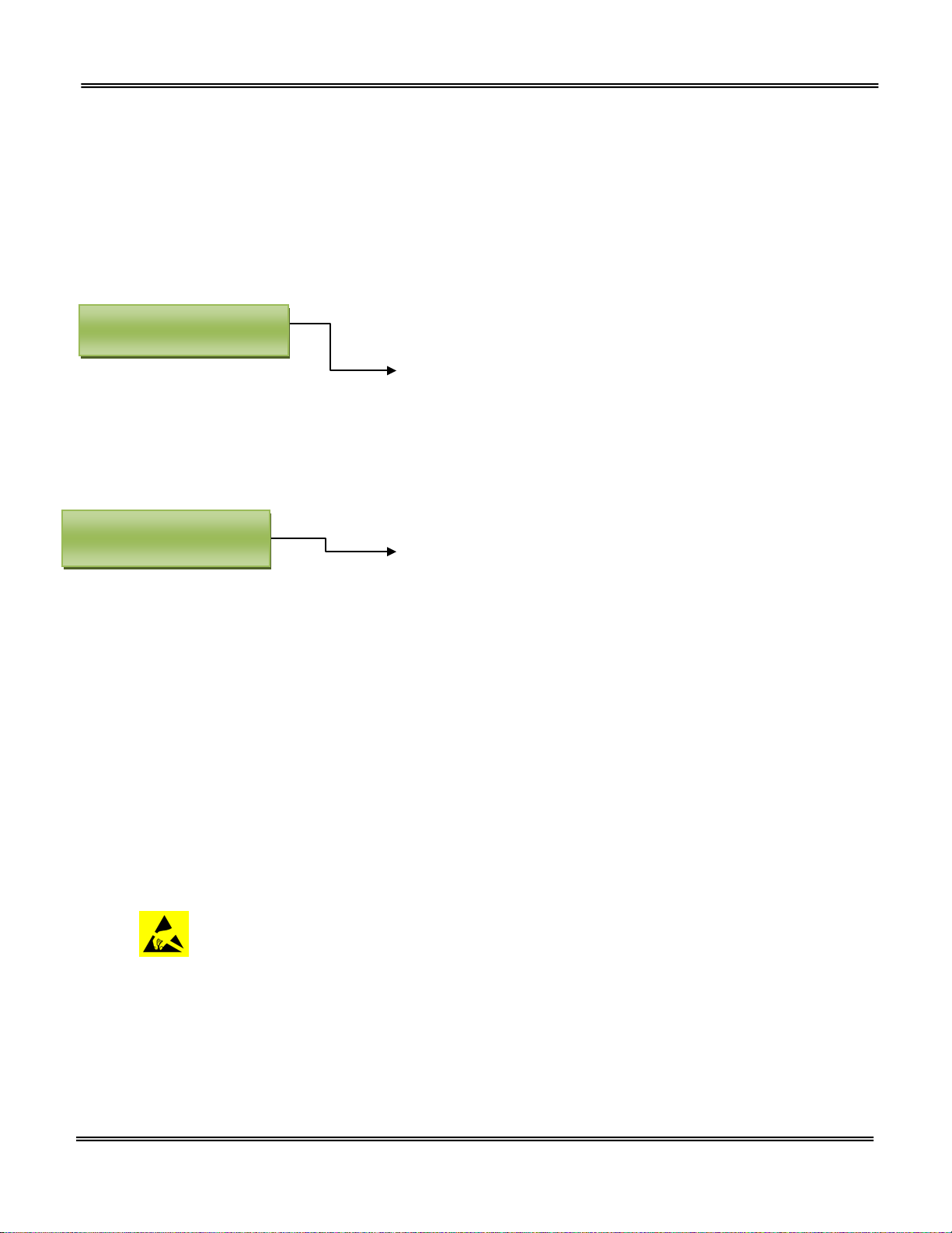
Connect ground
Power 24-28 V DC
Electrical Connections
Incoming power and signal output connections are made to a terminal block mounted inside a small
enclosure attached on the side of the main enclosure. Bring power cable through the cable gland and
secure the lugs of the cable to the terminal block as shown below. Connect the positive wire to the plus
terminal and minus wire to the minus terminals of the terminal block.
Advanced Instruments Inc.
terminal to Ground
Do not supply voltage more than specified in this manual and noted near the power input terminal of the
transmitter.
In order to maintain the intrinsic safety of the transmitter, the power must be supplied through an ATEX approved
intrinsic safety barrier. The factory recommended intrinsic safety barrier is MTL 7706+ or equivalent.
Without the use of intrinsic safety barrier or use of an improper safety barrier will void intr insic safety rating (see below)
of the transmitter.
The transmitter must be grounded by making a ground connection with the screw terminal marked as Ground.
With intrinsically safe power, this configuration of the GPR-2500 N conforms to the ATEX Directives 94/9/CE for
equipments for use in hazardous area. The analyzer meets the following area classification:
II 2 G
Ex ia IIB T4 Gb
T
With the use of recommended intrinsic safety barrier, the GPR-2500 N also meets the intrinsic safety standards
required for use in Class 1, Division 1, Group C, D hazardous areas.
-20⁰C to +50⁰C
amb
Avoid electrostatic discharge – Clean all non-metallic surfaces with a damp cloth only.
14
Page 16
Advanced Instruments Inc.
Installation in Hazardous Area
The GPR-2500 N may be installed in a hazardous area. However, in order to maintain the intrinsic safety rating of the
transmitter, total power coming to the transmitter must be limite d to a safe level. This can be achieved by using the
recommended safety barrier, MTL7706+ or equivalent. The intrinsic safety barrier has a built in power limiting circuitry
that keeps the maximum power going to the transmitter to a safe level even under fault conditions.
The maximum supply to the safety barrier is limited to 36 volts but the lowest voltage required is 24 VDC.
The intrinsic safety barrier must be installed in a safe area.
Output Connection
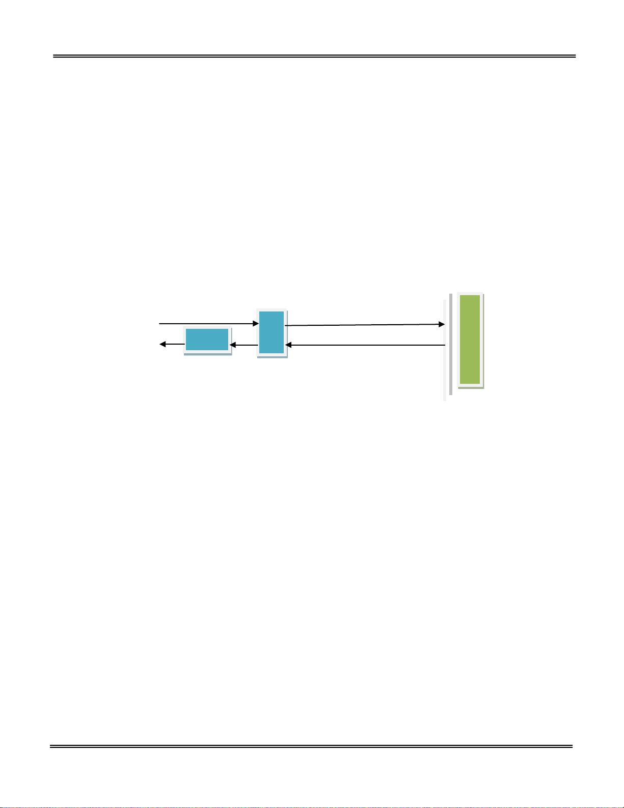
The 4-20mA current output is measured in the power loop by connecting a current measur ing dev ice between the
negative terminal of the power source and the negative terminal, marked (-), of the power input terminal block located
in the small enclosure. The current flow is from positive terminal of the power source to the positive terminal of the
transmitter and back to the negative terminal of the power source.
To measure the 4-20 mA signal output, connect an ammeter, as illustrated below. To convert the 4-20 mA in to 1-5
VDC, place a 250 Ohms resister in place of the current meter and measure the voltage across the resister.
24-28VDC
+ + +
_ _ _
Current Measuring Device Intrinsic Safety Barrier
4-20 mA MTL7706+ or Equivalent
4-20 mA Measuring Device Transmitter
Caution: To prevent accidental damage to the Intrinsic Safety Barrier, it is highly recommended that an
additional Fuse rated at 100 mA at 30 VDC be placed ahead of the intrinsic safety barrier.
Procedure
Power requirements consist of a two wire shielded cable, intrinsic safety barrier and a 24-36 V DC power supply.
Mount the intrinsic safety barrier on the din rail or other mounting device and ensure that the mounting bracket of the
intrinsic safety barrier is connected to the ground.
Connect the power to the two terminals of the intrinsic safety barrier marked as SAFE (terminal 1 + and terminal 2 -)
Connect a two wire shielded cable to the two terminals of the intrinsic safety barrier marked as HAZ (terminal 3 + and
terminal 4 -)
Run the shielded cable from HAZ through a proper conduit and through the cable gland and connect the two ends of
the shielded cable to the two terminals of the transmitter marked as + and –
Replace the cover of the small power input enclosure.
Connect the ground terminal of the transmitter to a proper ground.
Connect the ground of the safety barrier to the mounting rail (without rail ground, the transmitter will not power up)
15
Page 17
Advanced Instruments Inc.
Installing Oxygen Sensor
The GPR-2500 N Oxygen Transmitter is equippe d w ith an integral flow-through Delrin adopter with SS fittings and
tubing. The oxygen sensor simply screws in the adopter. The seal between the flow-through adopter and the oxygen
sensor is achieved by an integral o-ring (over the threaded spout) and the steeped sealing surface of the flow-through
adopter. Optional stainless steel sensor housing is available for oxygen measurements in highly corrosive applications.
The transmitter has been tested and calibrated by the manuf actur er prior to shipm ent and i s fully operational from the
shipping container.
Caution: All transmitters must be calibrated once the installation has been completed and periodically
thereafter as described below. Following the initial installation and calibration, allow the transmitters to
stabilize for 1-2 hours and re-calibrate the transmitter with a certified span gas.
Caution: DO NOT dissect t he ox y gen sensor. The sen sor co ntain s a corrosiv e liq uid ele ctr oly te that could be harmful if
touched or ingested, refer to the Material Safety Data Sheet in Section 10. Avoid contact with any liquid or
crystal type powder in or around the sensor or sensor housing, as either could be a form of electrolyte.
Leaking sensors should be disposed off in a manner similar to that of a common battery in accordance with
local regulations.
Avoid Electrostatic Discharge – Clean all non-metallic surfaces with a damp cloth only.
Procedure
1. Remove the four (4) screws securing the lid of the transmitter to the bottom of the enclosure.
2. Lift the door up until you hear a “click” sound (the hinge of the door will look itself thus preventing the door
from falling back). Caution: Do not remove the gaskets from either the enclosure. Failure to reinstall the
gasket will void the NEMA 4 rating and EMI/RFI protection.
3. Remove the oxygen sensor from the bag.
4. Remove the spring from inside of the round metal connector of the sensor (the spr ing kee p s the positiv e and
negative terminals of the sensor shorted to ensure that sensor is ready to use in a relatively short period of
time after installation). Note: After removing the spring, the sensor must be connected to the sensor cable
immediately. Failure to do so will prolong the time the sensor will require to stabilize.
5. Screw the oxygen sensor into t he sensor housing. Finger tighten plus one eighth (1/8) turn to ensure a good
seal between the sensor housing and the o-ring affixed to the sensor.
6. Assure the keyway registration of the female plug on the cable and male receptacle on the sensor match up.
7. Push the female plug (including the knurled lock nut) molded to the cable into the male receptacle attached to
the new sensor.
8. Screw the knurled lock nut attached with the cable onto to the male connector of the sensor.
9. Close the door of the enclosure and tig hten t he four scr ews assuring that the gask et is firmly in place between
the door and the body of the enclosure.
10. Proceed to calibration.
16
Page 18

Advanced Instruments Inc.
S1010 1.17
20.9%
76 F
Span Gas Preparation
The GPR-2500 N can be calibrated by using ambient air. However, it can also be calibrated by using a certifi ed spa n
gas. Air calibration can be achieved right after installing the sensor in the housing. Subsequent calibration, where the
sensor has been exposed to a sample gas, air calibration can be achieved by either removing the sensor from the
sensor housing or by pushing the air through the sensor housing.
Establishing Power
Once the two power input wires of the shielded cable are properly connected to the terminals inside the enclosure as
described above, connect the other end of the two wires to a suitable 24-28 VDC power supply such as a battery, PLC,
DCS, etc.
The digital display responds instantaneously. When power is applied, the transmitter performs several self-diagnostic
system status checks termed as “START-UP TEST” as illustrated below:
START-UP TEST
ELECTRONICS – PASS
BATTERY- PASS
TEMP SENSOR – PASS
BARO SENSOR – N/A
After self diagnostic tests, the analyzer turns itself into the sampling mode. And displays oxygen contents the sensor is
exposed to, the analysis range, and the ambient temperature.
AUTO SAMPLING
25% RANGE
Menu Navigation
The four (4) pushbuttons located on the front of the transmitter control all of the micro-processor functions:
Blue ENTER (select)
Yellow UP ARROW
Yellow DOWN ARROW
Green MENU (escape)
Main Menu
To access the MAIN MENU, press the MENU (ESC) key and the following screen will appear.
17
Page 19
Advanced Instruments Inc.
76 F
1.25 %
76 F
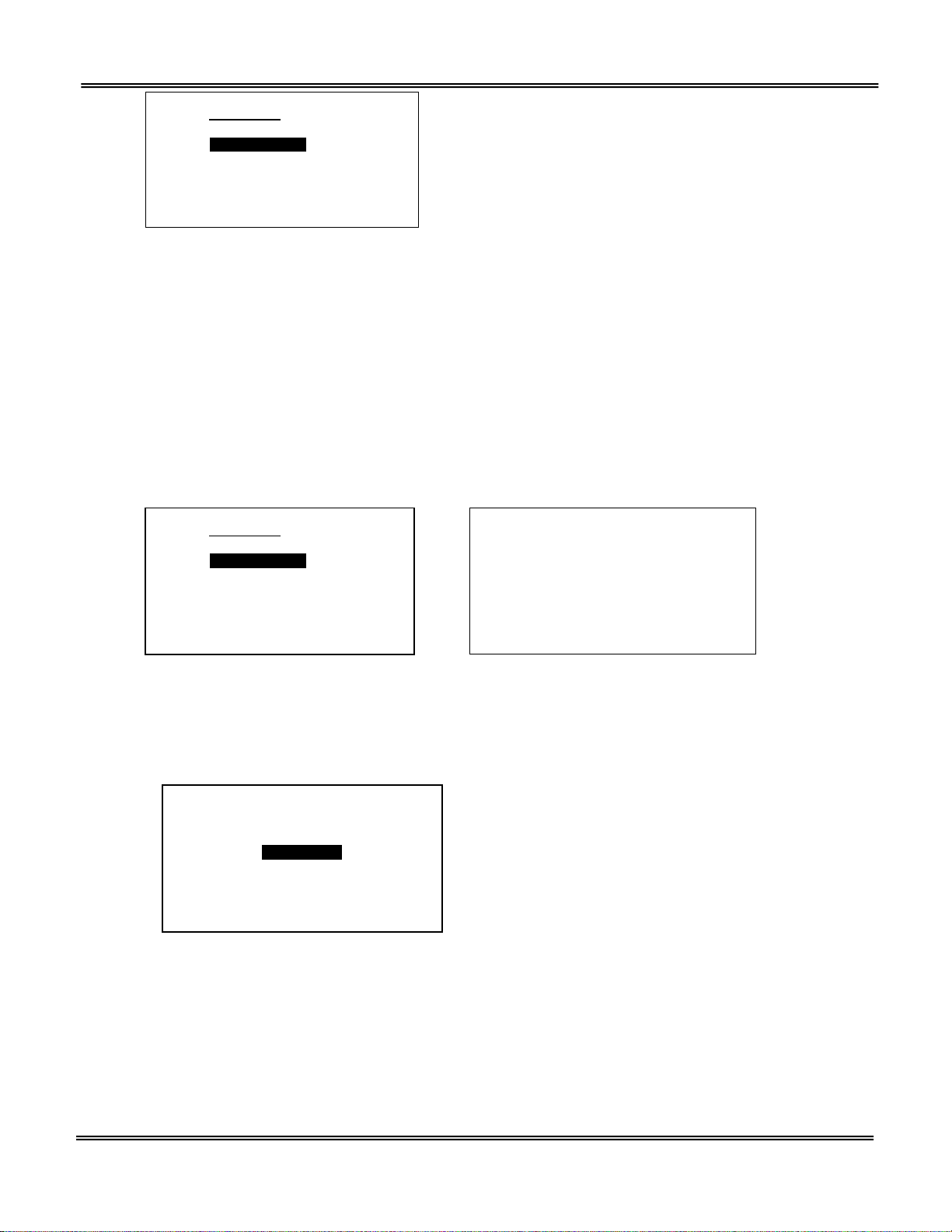
MAIN MENU
SELECT RANGE
CALIBRATION
VIEW HISTORY
SYSTEM OPTIONS
This screen show various option available. You can use the UP and DOWN arrow key to move the cursor and highlight
the desired function. After moving the cursor to the desired function, you can press ENTER to get to that function
The GPR-2500 N analyzer is equipped with four (4) standard measuring ranges (see specification) and provides users
with a choice of sampling modes. By accessing the MAIN MENU, users may select either the AUTO SAMPLING
(ranging) or MANUAL SAMPLING (to lock on a single range) mode.
Auto/Manual Sampling
Access the MAIN MENU by pressing the MENU key.
Advance the reverse shade cursor using the ARROW keys to highlight SELECT RANGE and press ENTER
The display will show *AUTO and the actual range of analysis. Press the ENTER to select MANUAL RANGE and
advance the cursor to the desired RANGE and press ENTER.
The following display appears:
MAIN MENU
SELECT RANGE
CALIBRATION
VIEW HISTORY
SYSTEM OPTIONS
SELECT RANGE
*AUTO
25%
10%
5%
*1%
In the AUTO range, the display will shift to the next higher range when the oxygen reading exceeds 99.9% of the upper
limit of the current range. The display will shift to the next lower range when the oxygen reading drops to 85% of the
upper limit of the next lower range. In MANUAL range, the analyzer will be locked on the selected range. If the oxygen
value goes above 25% of the upper limit of the MANUAL selected range, an OVER RANGE warning will be displayed.
OVERRANGE
M ANUAL SAMPLING
1% RANGE
Once the OVER RANGE warning appears the user must advance to the next higher range.
NOTE: With oxygen reading above 25% of the selected range, the analog signal output will increase but will freeze at a
maximum value of 1.2 V. After the oxygen reading falls below the full scale range, the voltage signal will become
normal.
18
Page 20
Advanced Instruments Inc.
0.015 %
Analyzer Calibration
The electrochemical oxygen sensors generate an electrical current that is linear or proportional to the oxygen
concentration in a sample gas. In the absence of oxygen the sensor exhibits an absolute zero, i.e., the sensor does
not generate a current output in the absence of oxygen. Given the properties of linearity and an absolute zero, a single
point calibration is possible.
The analyzer is equipped with “Zero Calibration” feature. However, as described below, zero calibration is
recommended only when the application (or user) demands optimum accuracy of below 5% of the most sensitive or
lowest range available on the analyzer. For example, if the user requires analysis of a sample gas below 0.05%, zero
calibration may be required.
Span calibration, it is necessary to adjust the analyzer sensitivity for accurate measurements of oxygen by using a
standardized (certified) oxygen or by using ambient air (20.9%).
Zero Calibration
The maximum zero offset correction is limited to a maximum of 50% of the lowest (most sensitive) range for positive
zero offset and 10% of the lowest range for negative zero offset.
Zero calibration should be carried out after the span calibration and once performed should not have to be repeated
with subsequent span calibrations. Normally, zero calibrations are performed when a new sensor is installed or
changes are made in the sample system connections. Allow the ZERO gas to flow through the analyzer and wait until
the signal has dropped to a low value and is stable.
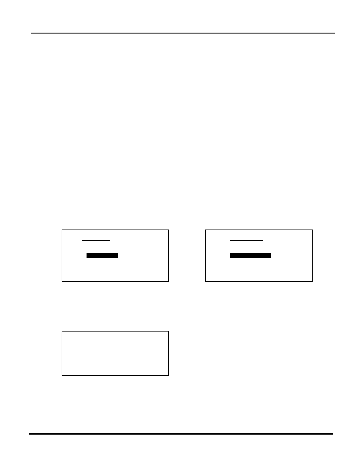
Access the MAIN MENU by pressing the MENU key.
Advance the reverse shade cursor using the ARROW keys to highlight CALIBRATION.
Press the ENTER key to select the highlighted menu option.
The following displays appear:
MAIN MENU
SELECT RANGE
CALIBRATION
VIEW HISTORY
SYSTEM OPTIONS
Advance the reverse shade cursor using the ARROW keys to highlight ZERO CALIBRATE.
Press the ENTER key to select the highlighted menu option.
The following displays appear:
ZERO CALIBRATION
WAIT FOR STEADY RDG
ENTER TO C ALIBRATE
MENU TO ABORT
Wait until the analyzer reading stabilizes (depending on the history of the sensor, it may take a few minutes to severa l
hours) and then press the ENTER key to calibrate (or MENU key to abort).
If the offset is less than 50% of the lowest range, by pressing ENTER will pass the calibration and the analyzer will
return to the Sample mode. On the other hand, if the offset is above 50%, pressing ENTER will fail calibration and the
analyzer will return to Sample mode without completing the Zero calibration.
19
>>>
CALIBRATION
SPAN CALIBRATE
ZERO CALIBRATE
DEFAULT SPAN
DEFAULT ZERO
OUTPUT SPAN
OUTPUT SIMULATE
Page 21
0.25%
Both the Zero Calibrate and Span Calibrate functions result in the following displays:
Advanced Instruments Inc.
CALIBRATION
PASSED
OR
FAILED
CALIBRATION
Default Zero
This feature will eliminate any previous zero calibration adjustment and display the actual signal output of the sensor at
a specified oxygen concentration. This feature allows the user to ensure that the accumulative zero offset never
exceeds 50% of the lowest range limit. To perform Default Zero,
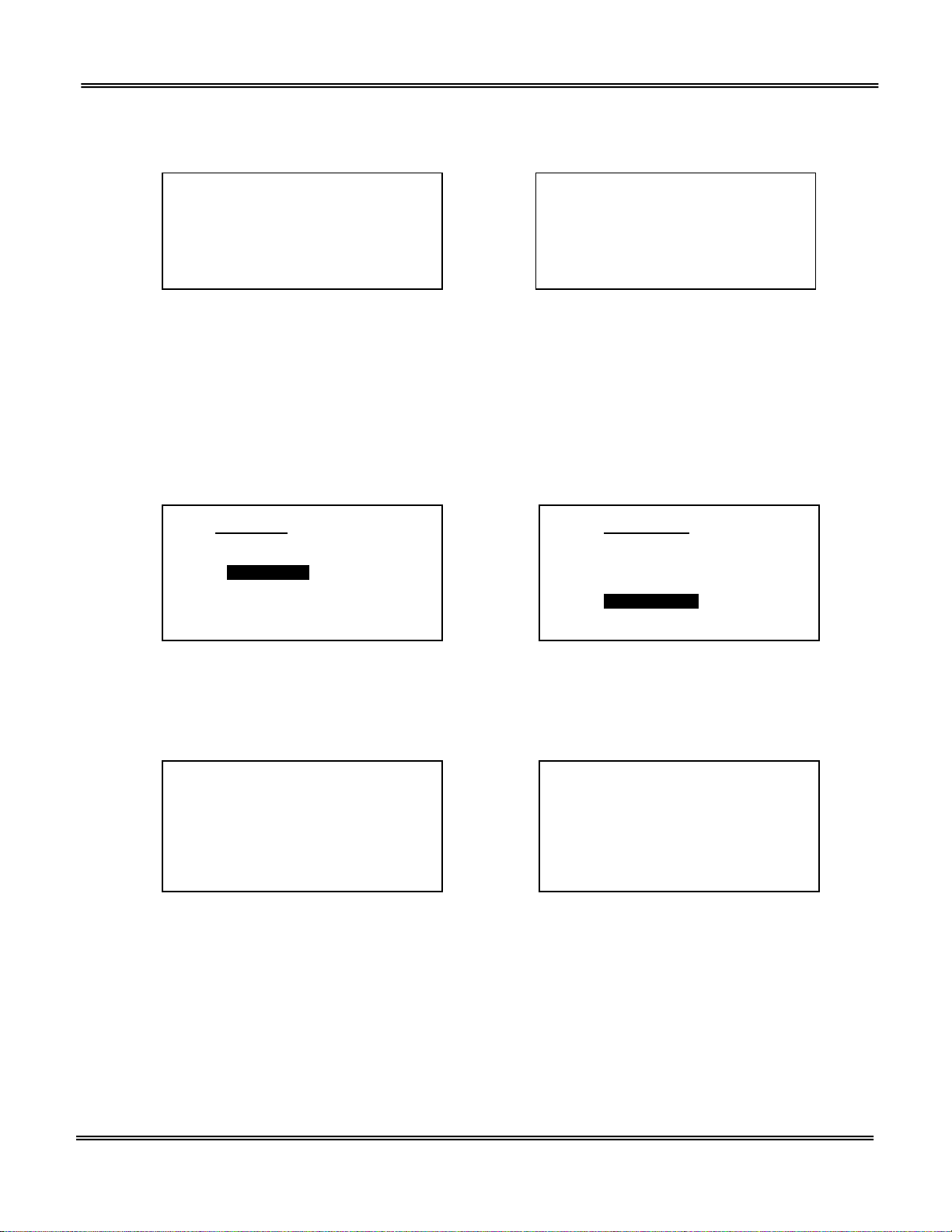
Access the MAIN MENU by pressing the MENU key.
Advance the reverse shade cursor using the ARROW keys to highlight CALIBRATION.
Press the ENTER key to select the highlighted menu option.
The following displays appear:
MAIN MENU
SELECT RANGE
CALIBRATION
VIEW HISTORY
SYSTEM OPTIONS
>>>
Advance the reverse shade cursor using the ARROW keys to highlight DEFAULT ZERO.
Press the ENTER key to select the highlighted menu option.
The following display appears and after 3 seconds the system returns to the SAMPLING mode:
CALIBRATION
SPAN CALIBRATE
ZERO CALIBRATE
DEFAULT SPAN
DEFAULT ZERO
OUTPUT SPAN
OUTPUT SIMULATE
FACTORY
DEFAULTS
SET
>>>
AUTO SAMPLING
1% RANGE
76 F
Analog Output Adjustment-Calibrate Output Span
In rare instances the 0-1 V signal output may not agree with the reading displayed on the LCD. This feature enables
the user to adjust the 0-1 V signal output.
Access the MAIN MENU by pressing the MENU key.
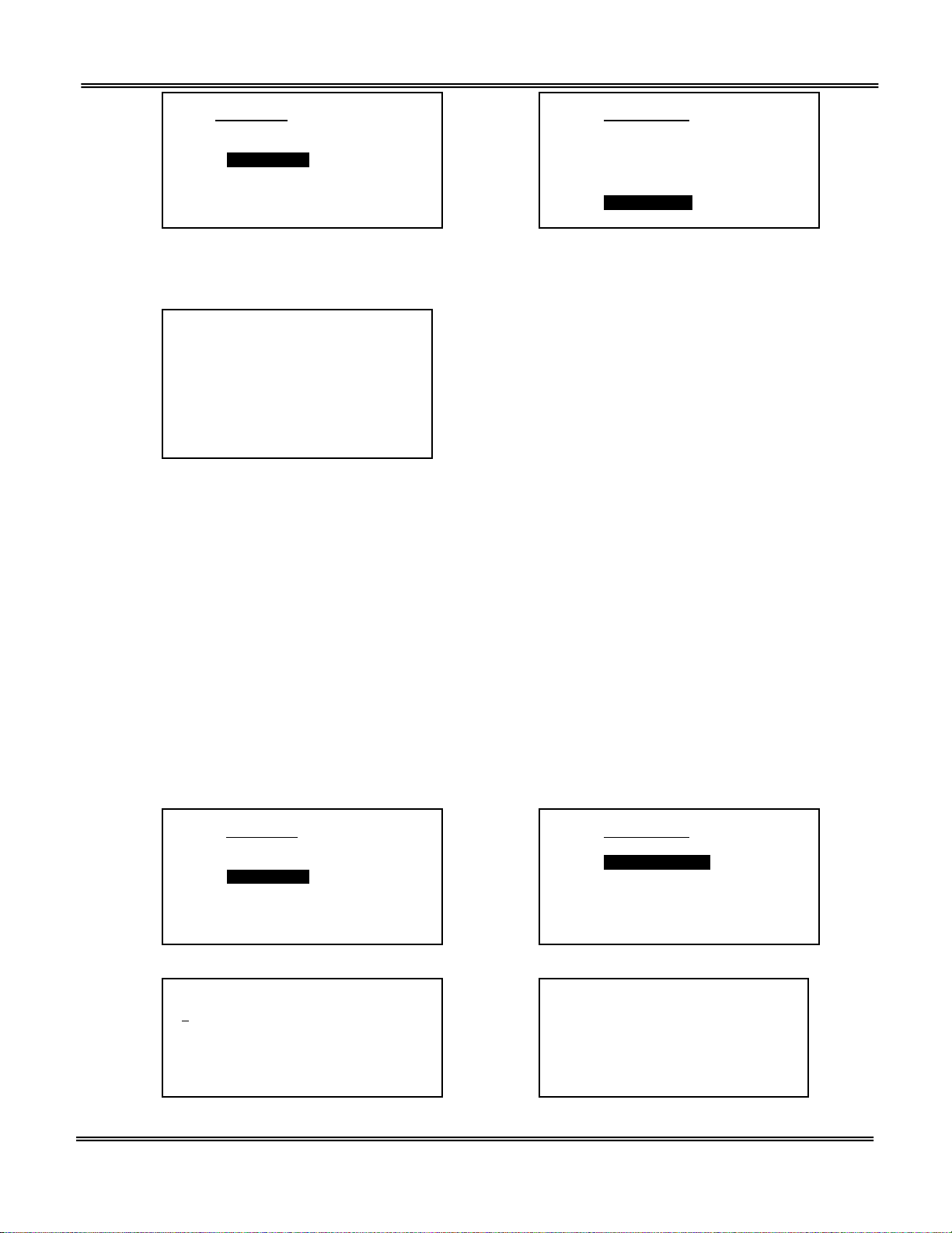
Advance the reverse shade cursor using the ARROW keys to highlight CALIBRATION.
Press the ENTER and then advance the cursor to OUTPUT SPAN and press ENTER. The following display s app ear:
20
Page 22
Advanced Instruments Inc.
MAIN MENU
SELECT RANGE
CALIBRATION
VIEW HISTORY
SYSTEM OPTIONS
>>>
CALIBRATION
SPAN CALIBRATE
ZERO CALIBRATE
DEFAULT SPAN
DEFAULT ZERO
OUTPUT SPAN
OUTPUT SIMULATEPA
Press the ENTER key to select the highlighted menu option and the following display appears:
OUTPUT SPAN
1 V ADJUST
PRESS UP OR DOWN
TO ADJUST OUTPUT
ENTER/MENU TO SAVE
By pressing UP or DOWN arrow, the signal output will change. Keep pressing the Up or DOWN key until the output is
1V. Note: To perform "Calibrate-Output Span", an external recording device must be connected to the signal output
port of the analyzer.
Press ENTER to SAVE the changes.
Span Calibration Procedure
Air Calibration
This procedure requires only a source of clean ambient air and removal of the sensor from its flow housing.
Access the interior of the analyzer by removing the 4 clamps securing the door of the analyzer.
Caution: Do not remove the gaskets from the enclosure. Failure to do so will void the NEMA rating.
Remove the sensor from the screw-in sensor housing or push the air through the analyzer SAMPLE IN thus exposing
the sensor to ambient air or alternatively, flow a certified span gas through the analyzer.
Advance the cursor on the MAIN MENU to CALIBRATE and press ENTER.
Advance the cursor to SPAN CALIBRATION and press ENTER
The following displays appear:
MAIN MENU
SELECT RANGE
CALIBRATION
VIEW HISTORY
SYSTEM OPTIONS
>>>
GAS CONCENTRATION
20.09%
PRESS UP OR DOWN
TO CHANGE VALUE
ENTER TO SAVE
MENU TO RETURN
>>>
21
CALIBRATION
SPAN CALIBRATE
ZERO CALIBRATE
DEFAULT SPAN
DEFAULT ZERO
OUTPUT SPAN
OUTPUT ZERO
20.01%
SPAN CALIBRATION
WAIT FOR STEADY RDG
ENTER TO CALIBRATE
MENU TO ABORT
Page 23

Advanced Instruments Inc.
0.010 %
By using the UP or DOWN arrow keys, enter the appropriate digit where the cursor is blinking
Press the ENTER key to advance the underline cursor right or press the MENU key to advance the underline cursor left
to reach to the desired digit of the gas value.
Repeat until the complete span value has been entered.
In the example above, a span value of 20.09% has been entered.
After the span value has been entered, the analyzer will prompt to press the ENTER key to accept SPAN
CALIBRATION or MENU to escape.
Caution: Allow the analyzer reading to stabilized before accepting calibration.
After successful calibration, the analyzer will display a message “Passed Calibration” and return to the Sample mode.
NOTE: The analyzer is allowed to accept calibration when O2 reading is within the acceptable value. If the O2 reading
is outside of this limit, by pressing ENTER to accept calibration will result in “Failed Calibration” and return to the
Sample mode without completing Span calibration. After pressing ENTER either of the following two messages will be
displayed and the analyzer will return to SAMPLE mode.
CALIBRATION
PASSED
OR
FAILED
CALIBRATION
Default Span
The software will set the SPAN adjustment based on the average output of the oxygen at a specific oxygen
concentration and erase any previous span calibration data. For example, with factory default settings, when a span
gas is introduced, the micro-processor will display oxygen reading within +
that the sensor output is within the specified limits. This feature allows the user to check the sensor’s signal output
without removing it from the sensor housing.
Access the MAIN MENU by pressing the MENU key.
Advance the reverse shade cursor using the ARROW keys to highlight CALIBRATION.
Press the ENTER key to select the highlighted menu option.
The following display appears:
MAIN MENU
SELECT RANGE
CALIBRATION
VIEW HISTORY
SYSTEM OPTIONS
>>>
Advance the reverse shade cursor using the ARROW keys to highlight DEFAULT SPAN.
Press the ENTER key to select the highlighted menu option.
The following displays appear and after 3 seconds the system returns to the SAMPLING mode:
30-50% of the span gas value, indicating
CALIBRATION
SPAN CALIBRATE
ZERO CALIBRATE
DEFAULT SPAN
DEFAULT ZERO
OUTPUT SPAN
OUTPUT SIMULATION
FACTORY
DEFAULTS
22
SET
76 F
AUTO SAMPLING
1 % RANGE
Page 24
Advanced Instruments Inc.
ADJUST
Analog Output Check- Output Simulate
This feature allows the user to simulate the electronics and the signal output. A know current is added to the analyzer
electronics internally to generate equivalent analog signal output. This feature allows the user to check all
interconnections from the analyzer to the signal output recording device before installation of sensor thus preventing
the user to open the sensor bag before the analyzer installation is complete and satisfactory. To simulate signal output
Access the MAIN MENU by pressing the MENU key.
Advance the reverse shade cursor using the ARROW keys to highlight CALIBRATION and then select OUTPUT
SIMULATE.
Press the ENTER key to select the highlighted menu option.
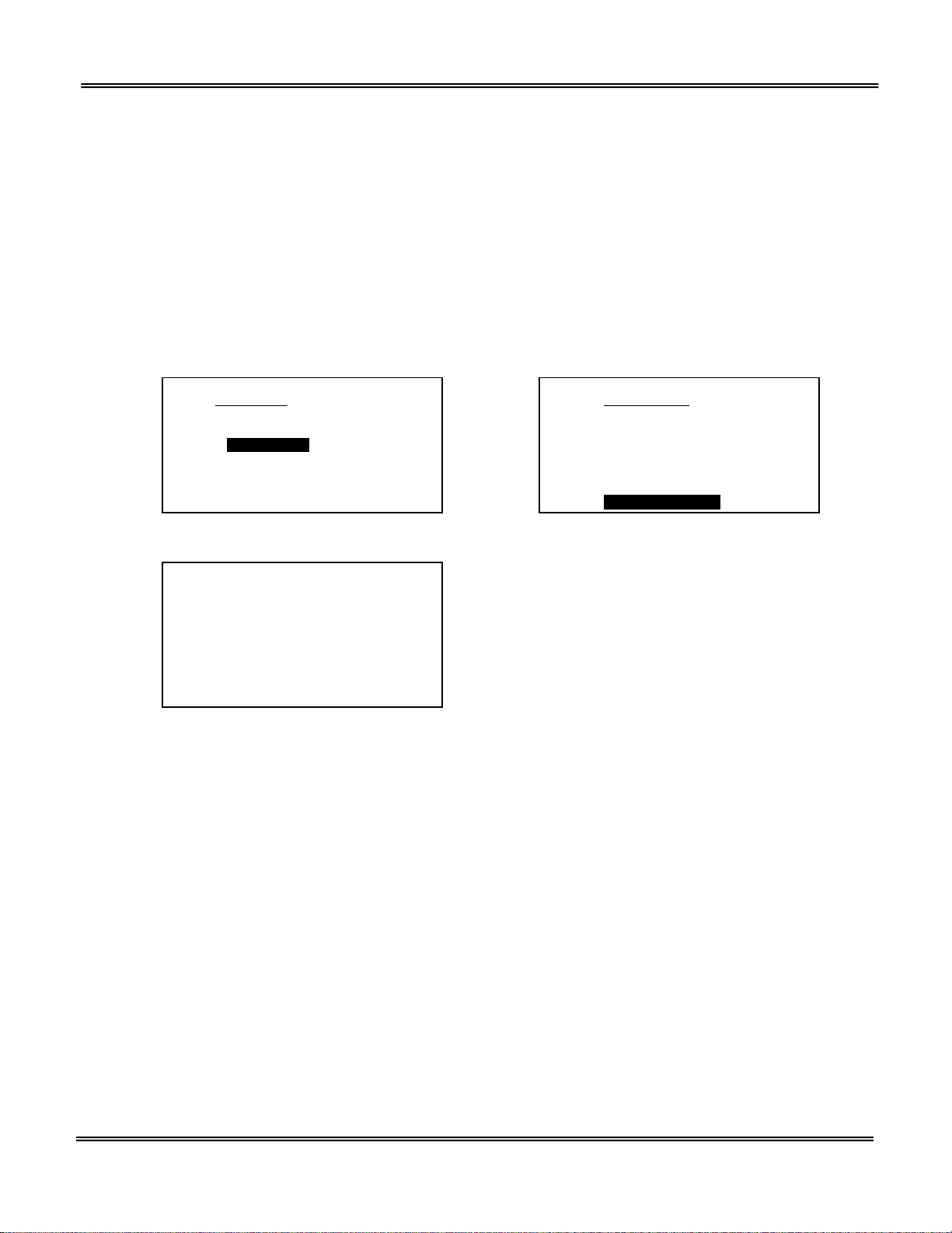
The following displays appear:
MAIN MENU
SELECT RANGE
CALIBRATION
VIEW HISTORY
SYSTEM OPTIONS
OUTPUT SIMULATION
0% S PAN
0.00 V
PRESS UP OR DOWN TO
OUTPUT ENTER/MENU TO RETURN
Pressing UP or DOWN key will increase or decrease the output by 5% of the full scale signal each time. Check the
output on the external recording device or voltmeter/ammeter. The output on the external recording would be the % of
the full scale signal selected, for example, 0% will represent 0.00 V, 25% value will represent 0.25 V and 50% span
value will represent 0.5 V of the 0-1 V full scale. After SIMULATION is complete, press ENTER/MENU key to return to
SAMPLE mode.
Note: To perform "Calibrate-Output Simulation", an external recording device must be connected between the negative
terminal of the power source and negative terminal of the transmitter.
>>>
CALIBRATION
SPAN CALIBRATE
ZERO CALIBRATE
DEFAULT SPAN
DEFAULT ZERO
OUTPUT SPAN
OUTPUT SIMULATEI
Analog Output Check- Output Calibrate
In certain cases, the full scale analog may not match with full scale display. This feature allows the user to adjust the
electronics so that the full scale display matches with full scale analog signal output. To calibrate full scale signal output
Access the MAIN MENU by pressing the MENU key.
Advance the reverse shade cursor using the ARROW keys to highlight CALIBRATION and then select OUTPUT
SIMULATE.
Press the ENTER key to select the highlighted menu option.
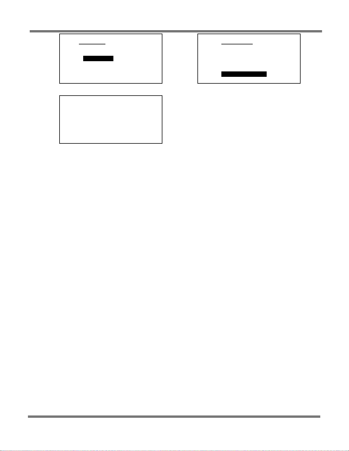
The following displays appear:
23
Page 25
Advanced Instruments Inc.
ADJUST
MAIN MENU
SELECT RANGE
CALIBRATION
VIEW HISTORY
SYSTEM OPTIONS
OUTPUT SIMULATION
20.0 mA ADJUST
PRESS UP OR DOWN TO
OUTPUT ENTER/MENU TO RETURN
Pressing UP or DOWN key will increase or decrease the full scale output signal each time. Check the output on the
external recording device or voltmeter/ammeter. Repeat this step until the out equals the full scale analog signal
expected, for example 20 mA in the present case. After OUTPUT CALIBRATION is complete, press ENTER/MENU key
to return to SAMPLE mode.
>>>
CALIBRATION
SPAN CALIBRATE
ZERO CALIBRATE
DEFAULT SPAN
DEFAULT ZERO
OUTPUT CALIBRATEI
OUTPUT SIMULATE
Sampling a Gas
GPR-2500 N Oxygen Analyzer requires a positive pressure to flow the sample gas across the sensor to measure the
oxygen concentration in a sample gas. If a positive sample pressure is not available, inst all an ex ter nal sample pu mp to
push the sample through the analyzer; see the option of using a sample pump as described above.
Procedure
Following calibration, the analyzer will return to the SAMPLE mode and ready for sampling the gas.
Select the desired sampling mode - auto or manual – as described abov e.
Use a suitable tubing to transport the sample gas to the analyzer
The main consideration is to eliminate any air leaks which can affect oxygen measurements.
For sample gases under positive pressure, the user must provide a means of controlling the inlet pressure between 530 psig.
For sample gases under atmospheric or slightly negative pressure, an optional integral sampling pump or an external
pump is necessary to push the sample through the sensor housing. Generally, when using a low voltage DC pump, no
pressure regulation or flow control device is involved. However, a flow meter upstream of analyzer is recommended to
ensure that the sample flow is adequate and steady.
Assure the sample is adequately vented for optimum response and recovery – and safety.
Allow the oxygen reading to stabilize for approximately 2 minutes at each sample point.
View History
This feature allows the user to view the maximum, minimum and average O2 concentration, maximum ambient
temperature, the number of days the sensor has been in service (at the time of installation and first calibrat ion, the user
must enter YES to confirm "new sensor") and the number of days since the last calibration was done.
System Options
This features allows the user to
1. Set security; password protected operation
2. Define ranges; choose a range between two ranges, for example, 2% full scale instead of 5% full scale.
3. Display signal below 0.00; negative signal, yes or no.
24
Page 26

Advanced Instruments Inc.
To enter password, from system option menu, select SECURITY, then enter four digit PASS CODE, numeral numbers
only and press ENTER. Then select AUTO LOCK option and enter the number of minutes after which access to MENU
options will be locked (access allowed only after entering the PASS CODE).
In the vent the PASS CODE is lost, enter the factory default PASS CODE 2855 to access the MENU and then renter
the new PASS CODE.
Choosing the option to display negative number will allow the user to see the display below 0.00 but the output will be
locked at 0.00 VDC.
Standby
The transmitter has no special storage requirements.
The sensor should remain connected during storage periods.
Store the transmitter with the power OFF at a safe location and away from a direct heating source.
If storing for an extended period of time protect the analyzer from dust, heat and moisture.
6. Maintenance
Generally, replacing the oxygen sensor is the extent of the maintenance requirements of this transmitter. Should any
other component, e.g., PCB, LCD, Safety Barrier, fail consult factory before proceeding for repair.
To replace sensor, refer to the section “INSTALLATION THE OXYGEN SENSOR” above.
Serviceability: Except for replacing the oxygen sensor, there are no parts inside the transmitter for the operator to
service. Only trained personnel with the authorization of their supervisor should conduct maintenance.
25
Page 27

Item No.
Description
GPR-11-32-4
Oxygen Sensor, for measuring O2 in inert gases
XLT-11-24-4
Oxygen Sensor, for measuring O2 in gases
containing CO2
Item No.
Description
A-3051
BARR-1001
Sensor Housing Flow Adapter
Intrinsic Safety Barrier MTL7706+
MTR-1010
Meter Digital Panel LCD
A-1161-IS-2 Rev C4
PCB Assembly Main / Display
A-1182
PCB Assembly 4-20 Loop Current Control
7. Spare Parts
Recommended spare parts for the GPR-2500 N Oxygen Transmitter:
Other spare parts:
Advanced Instruments Inc.
26
Page 28

Symptom
Possible
Cause
Recommended
Actions
Replace sensor
factory for warranty determination
8. Troubleshooting
Advanced Instruments Inc.
Slow recovery to low
oxygen
High O2 reading after
installing or replacing
sensor
High O2 reading
Sampling
At installation, defective
sensor
Air leak in sample system
connection(s)
Abnormality in zero gas
Damaged in service prolonged exposure to air,
electrolyte leak
Sensor nearing end of life
Transmitter calibrated
before sensor stabilized
caused by:
1) Air leak in sample
system connection(s)
2) Abnormality in zero gas
Flow rate exceeds limits
Pressurized sensor
Improper sensor selection
Replace sensor if recovery unacceptable
or O2 reading fails to reach 20% of lowest
range
Leak test the entire sample system: Vary
the flow rate, if the O
inversely with the change in flow rate
indicates an air leak - correct source of
leak
Qualify zero gas (using portable
transmitter)
Replace sensor
Allow O2 reading to stabilize before
making the span/calibration ad just men t
Continue purge with zero gas
Leak test the entire sample system
(above)
Qualify zero gas (using portable
transmitter)
Correct pressure and flow rate
Remove restriction on vent line
Replace GPR/PSR sensor with XLT
sensor when CO
present
reading changes
2
or acid gases are
2
Response time slow
O2 reading doesn’t
agree with expected
values
O
2
Erratic O2 reading
or
reading
No O
2
27
Air leak, dead legs, distance
of sample line, low flow rate,
volume of optional filters and
scrubbers
Pressure and temperature of
the sample is different than
span gas
Abnormality in gas
Change in sample pressure
Bad sensor cable connection
Defective sensor
Leak test (above), reduce dead volume or
increase flow rate
Calibrate the transmitter (calibrate at
pressure and temperature of sample)
Qualify the gas (use a portable transmitter)
Calibrate the transmitter (calibrate at
pressure and temperature of sample gas)
Check sensor cable connections, replace
sensor cable if necessary
Replace sensor and return sensor to the
Page 29

Advanced Instruments Inc.
Liquid covering sensing area
Erratic O2 reading
or
Negative O
reading
2
or
reading
No O
2
accompanied by
electrolyte leakage
Improper sensor selection
Presence of interference
gases
Unauthorized maintenance
Sensor nearing end of life
Pressurizing the sensor by
flowing gas to the sensor with
the vent restricted or SHUT
OFF valve closed and
suddenly removing the
restriction draws a vacuum
on the sensor
or
partially opening the valves
upstream of the transmitter
when using a pump
downstream of the
transmitter to draw sample
from a process at
atmospheric pressure or a
slight vacuum. Placing a
vacuum on the sensor in
excess 4” of water column is
strongly discouraged.
A premature adjustment of
the ZERO OFFSET
potentiometer is a common
problem
Sensor: Replace if leaking and return it to
the factory for warranty determination
Replace GPR/PSR sensor with XLT sensor
when CO
or acid gases are present.
2
Consult factory.
Replace sensor and install scrubber
Consult factory.
Replace sensor
Confirm sample is vented to atmospheric
pressure. Confirm no restriction on vent
line. Zero the transmitter. If not successful
replace the sensor
Avoid drawing a vacuum on the sensor.
From MAIN MENU select DEFAULT ZERO
28
Page 30

Advanced Instruments Inc.
9. Warranty
The design and manufacture of GPR Series oxygen analyzers, monitors and oxygen sensors are performed under a
certified Quality Assurance System that conforms to established standards and incorporates state of the art materials
and components for superior performance and minimal cost of ownership. Prior to shipment every analyzer is
thoroughly tested by the manufacturer and documented in the form of a Quality Control Certification that is included in
the Owner’s Manual accompanying every analyzer. When operated and maintained in accordance with the Owner’s
Manual, the units will provide many years of reliable service.
Coverage
Under normal operating conditions, the monitor, analyzers and sensor are warranted to be free of defects in materials
and workmanship for the period specified in accordance with the most recent published specifications, said period
begins with the date of shipment by the manufacturer. The manufacturer information and serial number of this analyzer
are located on the rear of the analyzer. Advanced Instruments Inc. reserves the right in its sole discretion to invalidate
this warranty if the serial number does not appear on the analyzer.
If your Advanced Instruments Inc. monitor, analyzer and/or oxygen sensor is determined to be defective with respect to
material and/or workmanship, we will repair it or, at our option, replace it at no charge to you. If we choose to repair
your purchase, we may use new or reconditioned replacement parts. If we choose to replace your Advanced
Instruments Inc. analyzer, we may replace it with a new or reconditioned one of the same or upgraded design. This
warranty applies to all monitors, analyzers and sensors purchased worldwide. It is the only one we will give and it sets
forth all our responsibilities. There are no other express warranties. This warranty is limited to the first customer who
submits a claim for a given serial number and/or the above warranty period. Under no circumstances will the warranty
extend to more than one customer or beyond the warranty period.
Limitations
Advanced Instruments Inc. will not pay for: loss of time; inconvenience; loss of use of your Advanced Instruments Inc.
analyzer or property damage caused by your Advanced Instruments Inc. analyzer or its failure to work; any special,
incidental or consequential damages; or any damage resulting from alterations, misuse or abuse; lack of proper
maintenance; unauthorized repair or modification of the analyzer; affixing of any attachment not provided with the
analyzer or other failure to follow the Owner’s Manual. Some states and provinces do not allow limitations on how an
implied warranty lasts or the exclusion of incidental or consequential damages, these exclusions may not apply.
Exclusions
This warranty does not cover installation; defects resulting from accidents; damage while in transit to our service
location; damage resulting from alterations, misuse or abuse; lack of proper maintenance; unauthorized repair or
modification of the analyzer; affixing of any label or attachment not provided with the analyzer; fire, flood, or acts of
God; or other failure to follow the Owner’s Manual.
Service
Call Advanced Instruments Inc. at 909-392-6900 (or e-mail [email protected] m) between 7:30 AM and 5:00 PM Pacific Time
Monday thru Thursday or 8:00 AM to 12:00 pm on Friday. Trained technicians will assist you in diagnosing the problem
and arrange to supply you with the required parts. You may obtain warranty service by returning you analyzer, postage
prepaid to:
Advanced Instruments Inc.
2855 Metropolitan Place
Pomona, Ca 91767 USA
Tel: 909 392 6900
Be sure to pack the analyzer securely. Include your name, address, telephone number, and a description of the
operating problem. After repairing or, at our option, replacing your Advanced Instruments Inc. analyzer, we will ship it to
you at no cost for parts and labor.
29
Page 31

Advanced Instruments Inc.
Product Identification
Product Name
Oxygen Sensor Series - PSR, GPR, AII, XLT
Synonyms
Electrochemical Sensor, Galvanic Fuel Cell
Manufacturer
Advanced Instruments Inc., 2855 Metropolitan Place, Pomona, CA 91767 USA
Emergency Phone Number
909-392-6900
Preparation / Revision Date
January 1, 1995
present a health hazard. Information applies to electrolyte unless otherwise noted.
Specific Generic Ingredients
Carcinogens at levels > 0.1%
None
Others at levels > 1.0%
Potassium Hydroxide or Acetic Acid, Lead
CAS Number
Potassium Hydroxide = KOH 1310-58-3 or Acetic Acid = 64-19-7, Lead = Pb 7439-92-1
Family
General Requirements
Use
Potassium Hydroxide or Acetic Acid - electrolyte, Lead - anode
Handling
Rubber or latex gloves, safety glasses
Storage
Indefinitely
Physical Properties
Boiling Point Range
KOH = 100 to 115° C or Acetic Acid = 100 to 117° C
Melting Point Range
KOH -10 to 0° C or Acetic Acid – NA, Lead 327° C
Freezing Point
KOH = -40 to -10° C or Acetic Acid = -40 to -10° C
Molecular Weight
KOH = 56 or Acetic Acid – NA, Lead = 207
Specific Gravity
KOH = 1.09 @ 20° C, Acetic Acid = 1.05 @ 20° C
Vapor Pressure
KOH = NA or Acetic Acid = 11.4 @ 20° C
Vapor Density
KOH – NA or Acetic Acid = 2.07
pH
KOH > 14 or Acetic Acid = 2-3
Solubility in H2O
Complete
% Volatiles by Volume
None
Evaporation Rate
Similar to water
odor
Fire and Explosion Data
Flash and Fire Points
Not applicable
Flammable Limits
Not flammable
Extinguishing Method
Not applicable
Procedures
Hazards
10. MSDS – Material Safety Data Sheet
Notes Oxygen sensors are sealed, contain protective coverings and in normal conditions do not
Chemical (Synonym) and
Potassium Hydroxide (KOH) – Base or Acetic Acid (CH3CO2H) – Acid, Lead (Pb) – Metal
Appearance and Odor Aqueous solutions: KOH = Colorless, odorl ess or Acetic Aci d = Colorless, vinegar-like
Special Fire Fighting
Unusual Fire and Explosion
Not applicable
Not applicable
30
Page 32

Advanced Instruments Inc.
Reactivity Data
Stability
Stable
Instability
Incompatibility
KOH = Avoid contact with strong acids or Acetic Acid = Avoid contact with strong bases
Products
Conditions to Avoid
KOH = None or Acetic Acid = Heat
Spill or Leak
time).
Disposal
In accordance with federal, state and local regulations.
Health Hazard Information
Primary Route(s) of Entry
Ingestion, eye and skin contact
OSHA PEL 10 % (TWA), Lead - OSHA PEL .05 mg/cubic meter
or Acetic Acid = Oral LD50 (RAT) = 6620 mg/kg
Eye
Electrolyte is corrosive and eye contact could result in permanent loss of vision.
Skin
Electrolyte is corrosive and skin contact could result in a chemical burn.
Inhalation
Liquid inhalation is unlikely.
Symptoms
Eye contact - burning sensation. Skin contact - soapy slick feeling.
Medical Conditions Aggravated
None
Monographs - not listed; OSHA - not listed
other reproductive harm.
Special Protection Information
Ventilation Requirements
None
Eye
Safety glasses
Hand
Rubber or latex gloves
Respirator Type
Not applicable
Other Special Protection
None
Special Precautions
Precautions
Do not remove the sensor’s protective Teflon and PCB coverings. Do not
Empty sensor body may contain hazardous residue.
Transportation
Not applicable
Conditions Contributing to
Hazardous Decomposition
None
KOH = None or Acetic Acid = Emits toxic fumes when heated
Steps if material is released Sensor is packaged in a sealed plastic bag, check the sensor inside for electrolyte
leakage. If the sensor leaks inside the plastic bag or inside an analyzer sensor housing
do not remove it without rubber or latex gloves and safety glasses and a source of
water. Flush or wipe all surfaces repeatedly with water or wet paper towel (fresh each
Exposure Limits Potassium Hydroxide - ACGIH TLV 2 mg/cubic meter or Acetic Acid - AC GIH TLV /
Ingestion Electrolyte could be harmful or fatal if swallowed. KOH = Oral LD50 (RAT) = 2433 mg/kg
Carcinogenic Reference Data KOH and Acetic Acid = NTP Annual Report on Carcinogens - not listed; LARC
Other Lead is listed as a chemical known to the State of California to cause birth defects or
probe the sensor with sharp objects. Wash hands thoroughly after handling.
Avoid contact with eyes, skin and clothing.
31
Page 33

Advanced Instruments Inc.
Appendix A
Electrical power must be within the recommended range (Maximum 36 VDC, Minimum 24 VDC). The power to the
transmitter must be provided through and ATEX approved intrinsic safety barrier. Factory recommended intrinsic safety
barrier is MTL7706+. This intrinsic safety barrier has the following rating
II (1) GD
[Ex ia] IIC
The barrier has a built in electronic circuitry that limit the total power delivered to the transmitter to a safe level even
under fault conditions.
Failure to use the intrinsic safety barrier will void the intrinsic safety rating of the transmitter.
The transmitter enclosure must be grounded with a good ground connection to prevent accidental damage to
the transmitter.
.
32
Page 34

Advanced Instruments Inc.
Appendix B
Matching - LCD Display with 4-20mA Output
In rare instances the 4-20mA signal output may not agree with the reading displayed on the LCD. The Output Zero and
Output Span features enable the user to adjust the 4mA and 20 mA signal output mat chi ng with the reading displayed
by the LCD.
For optimum accuracy make two separate adjustments as follows:
1. OUTPUT ZERO feature: To adjust the 4mA signal output and requires zero gas.
2. OUTPUT SPAN feature: To adjust the 20mA signal output and requires span gas near full range.
Note: In the field or in the absence of the preferred gases, use the OUTPUT SPAN feature and adjust the 20mA signal
output using the span gas available.
Procedure – regardless of type of adjustment:
1. When you select OUTPUT ZERO OR OUTPUT SPAN, the microprocessor defaults to 100% to start.
2. The “actual” 4-20mA signal output will be adjusted to the “theoretical” value of the LCD display.
3. Adjustment general rule:
a) If the actual 4-20mA value < the theoretical LCD value, the adjustment value will be > 100%.
b) If the actual 4-20mA value > the theoretical LCD value, the adjustment value will be < 100%.
4. Convert the “actual” reading of the LCD display to the “theoretical” 4-20mA as follows:
a) Divide the “actual” (% or percent) LCD reading by the value of the span gas available.
b) Multiply 16mA (20mA – 4mA) times the “result of a.”
c) Add 4mA plus the “result of b.” to obtain the “theoretical” 4-20mA signal output value.
5. Adjustment value: Divide the theoretical by the actual 4-20mA values and multiply by 100.
6. Enter the adjustment value via OUTPUT ZERO or OUTPUT SPAN routines described below.
Example: Analyzer reading is 60 % oxygen (100 % range) on 84 % span gas, 4-20mA signal output at PLC is
24mA
Solution: a) Use OUTPUT SPAN feature to make the adjustment.
b) Adjustment will be < 100% (default value of OUTPUT SPAN feature).
c) 13.6mA is the “theoretical” 4-20mA converted from the “actual” reading of the LCD.
60 % divided by 84 % = 0.71 or 71%
16mA multiplied by 0.71 = 11.36mA
4mA plus 11.36mA = 15.36mA “theoretical” 4-20mA signal output value
d) 15.36mA divided by 24mA the “actual” 4-20mA value = 64.0 adjustment value
e) Enter 64.0 via OUTPUT SPAN procedure below.
Output Zero
Access the MAIN MENU by pressing the MENU key.
Advance the reverse shade cursor using the ARROW keys to highlight CALIBRATION.
Press the ENTER key to select the highlighted menu option.
The following displays appear:
33
Page 35
Advanced Instruments Inc.
OUTPUT ZERO
100.0
MENU TO RETURN
000.0
MENU TO RETURN
OUTPUT ZERO
MAIN MENU
AUTO SAMPLE
MANUAL SAMPLE
CALIBRATION
>>>
CALIBRATION
SPAN CALIBRATE
ZERO CALIBRATE
DEFAULT SPAN
DEFAULT ZERO
OUTPUT SPAN
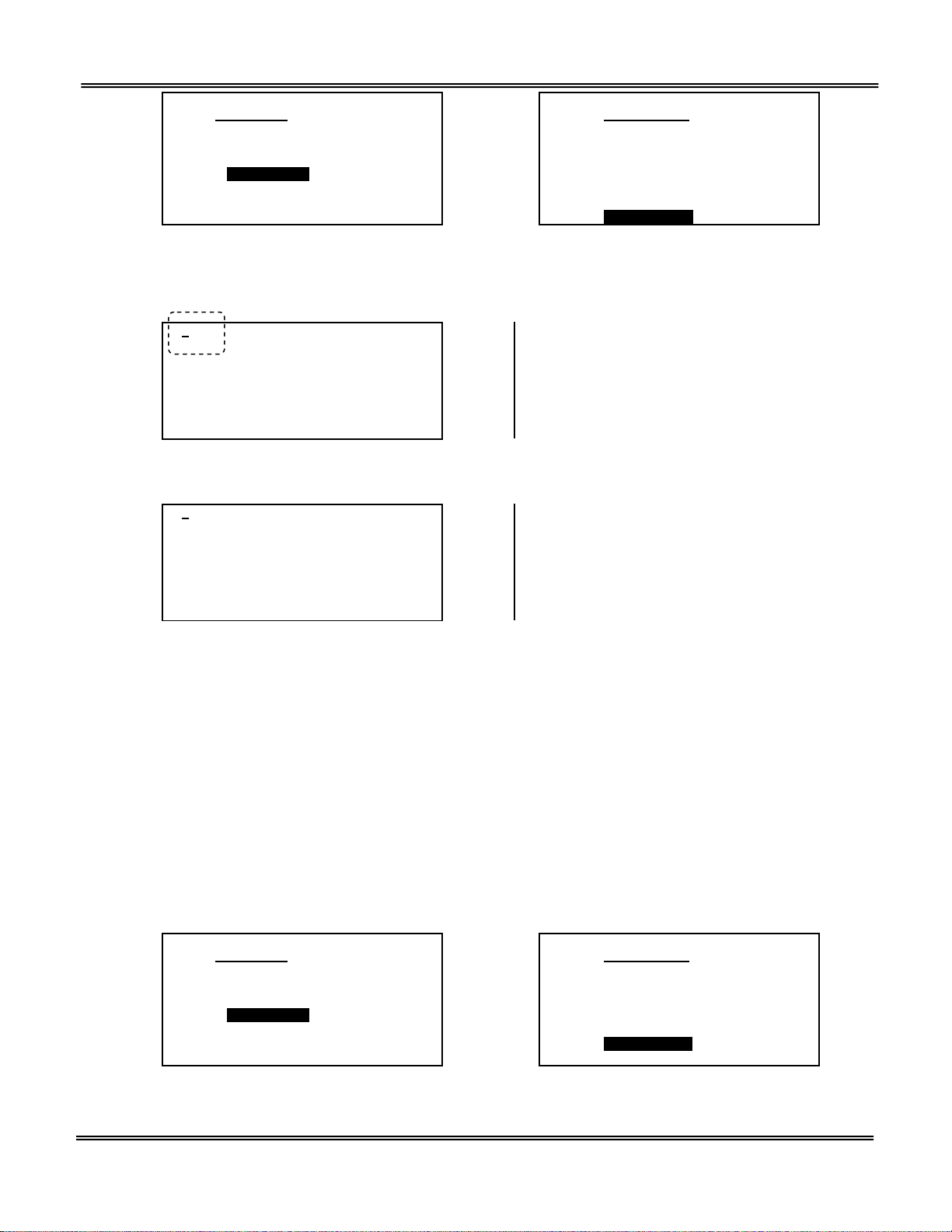
Advance the reverse shade cursor using the ARROW keys to highlight DEFAULT ZERO.
Press the ENTER key to select the highlighted menu option.
The following display appears:
OUTPUT ZERO OFFSET
PRESS UP OR DOWN
TO CHANGE VALUE
ENTER TO SAVE
Enter the calculated adjustment value. Note: Once the initial adjustment is made and checked at the PLC it may be
necessary to fine tune the initial adjustment by repeating. Any additional percent error must be added or subtracted
from the initial adjustment value
OUTPUT ZERO OFFSET
PRESS UP OR DOWN
TO CHANGE VALUE
ENTER TO SAVE
Press the ENTER key to advance the underline cursor right or press the MENU key to advance the underline cursor left
to reach to the desired digit of the adjustment OUTPUT ZERO OFFSET value.
Press the ARROW keys to enter each the numerical value of each digit of the adjustment OUTPUT ZERO OFFSET
value.
Repeat until the complete OUTPUT ZERO OFFSET value has been entered.
Save the adjustment value by pressing the ENTER key or abort by pressing the MENU key. The system will then return
to the SAMPLE mode.
Output Span
Access the MAIN MENU by pressing the MENU key.
Advance the reverse shade cursor using the ARROW keys to highlight CALIBRATION.
Press the ENTER key to select the highlighted menu option.
The following displays appear:
MAIN MENU
AUTO SAMPLE
MANUAL SAMPLE
CALIBRATION
>>>
Advance the reverse shade cursor using the ARROW keys to highlight OUTPUT SPAN.
Press the ENTER key to select the highlighted menu option.
34
CALIBRATION
SPAN CALIBRATE
ZERO CALIBRATE
DEFAULT SPAN
DEFAULT ZERO
OUTPUT SPAN
Page 36

100.0
MENU TO RETURN
064.0
MENU TO RETURN
The following display appears:
Advanced Instruments Inc.
OUTPUT SPAN OFFSET
PRESS UP OR DOWN
TO CHANGE VALUE
ENTER TO SAVE
Enter the calculated adjustment value, refer to example described above.
Note: Once the initial adjustment is
made and checked at the PLC it may be necessary to fine tune the initial adjustment by repeating. Any additional
percent error must be added or subtracted from the initial adjustment value
OUTPUT SPAN OFFSET
PRESS UP OR DOWN
TO CHANGE VALUE
ENTER TO SAVE
.
Press the ENTER key to advance the underline cursor right or press the MENU key to advance the underline cursor left
to reach to the desired digit of the adjustment OUTPUT SPAN OFFSET value.
Press the ARROW keys to enter the numerical value of each digit of the OUTPUT SPAN OFFSET value.
Repeat until the complete OUTPUT SPAN OFFSET value has been entered.
Save the adjustment value by pressing the ENTER key or abort by pressing the MENU key. The system will then return
to the SAMPLE mode
35
Page 37

Advanced Instruments Inc.
36
Page 38

Advanced Instruments Inc.
37
Page 39

Advanced Instruments Inc.
Appendix G
Maintenance – H2S Scrubber
Servicing any of the H2S scrubbers will depend on several factors as illustrated in Appendix F and include: the
(average) H2S concentration (average), volume of scrubber media and flow rate through the scrubber (often times
maximizing the service life means longer system response time) see Appendix F.
Required equipment:
1. 2x 7/16” open end wrenches
2. 1x 9/16” open end wrench
3. 1x 1” open end or adjustable wrench
Procedure:
Separate the top connection to the scrubber using a 7/16” and the 9/16” open end wrenches on the two top nuts.
Hold the second nut with the 9/16” open end wrench.
With one of the 7/16” open end wrenches turn the top nut counter clockwise until the fitting disengages.
Separate the bottom connection to the scrubber using both 7/16” open end wrenches.
Hold the nut at the bottom of the scrubber with a 7/16” open end wrench.
With the other 7/16” open end wrench turn the nut below counter clockwise until the fitting disengages.
Carefully, do not loose the ferrules inside the fitting, remove the stainless tubing from the top and bottom of the
scrubber.
Carefully pull the scrubber from its mounting clip which is attached to the back panel.
Once the scrubber is free, hold the scrubber with one hand and using the 1” open end or adjustable wrench with the
other hand, turn the 1” nut counter clockwise and remove the 1” nut at the top of the scrubber.
There is no need to remove the 7/16” fitting at the bottom of the scrubber.
With the 1” nut removed, empty the spent media through the opening.
Fill the scrubber with fresh media (should be rich purple in color).
Reverse the above steps to re-assemble and install the scrubber .
Maintenance – Coalescing Filter
Servicing the coalescing filter (P/N FLTR-1002-2) depends on the cleanliness and moisture content of the sample and
maintenance intervals.
Required equipment:
Channel locks
Damp rag
Lubricant (a thin coat applied to the o-ring after cleaning helps ensure a tight seal and extend o-ring life)
Procedure:
Unscrew the clear polycarbonate bowl by turning it counter clockwise.
Note: It is probably stuck tight – use the damp rag to grip if removing by hand or to prevent damage to the bowl if using
the channel locks.
The bowl seals to the head section with an o-ring, do not lose the o-ring.
The filter element screws into the head section, carefully turn it counter clockwise and remove.
Using the damp cloth, clean the inside of the bowl and the o-ring before reassembling – apply a very thin coat of
lubricant to the o-ring.
Reverse the above steps to re-assemble the filter.
38
 Loading...