

Page 1
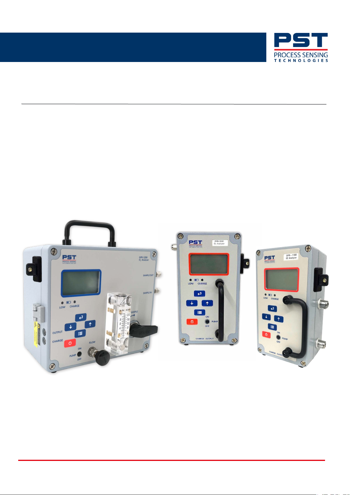
GPR-Portable Oxygen Analyzers
User Manual
PST-UM-3005-EN-01
PST-UM-3005-EN-01 07/2024
Page 2

GPR-Portables Oxygen Analyzer User Manual
Issue No. Description Date Author Initials
00 New document 02/2024 IM, CK, KS, JW, OP
01 GP information added 07/2024 IM, CK, WN
GPR-1100, GPR-1200, GPR-2000 Oxygen Analyzers
For contact information, visit
ProcessSensing.com
Analytical Industries Inc (Aii) is part of the Process Sensing Technologies Group (PST).
This document is the property of Process Sensing Technologies and may not be copied or otherwise reproduced,
communicated to third parties, nor stored in any Data Processing System without the express
written authorization of Process Sensing Technologies.
©2024 Process Sensing Technologies
ii ProcessSensing.com
Page 3
GPR-Portables Oxygen Analyzer User Manual
Before using your portable analyzer
Safety information
Please read this manual, ensuring that you fully understand the content before attempting to setup,
maintain or use the portable analyzer. Important safety information is highlighted throughout this
document as follows:
The electrical warning symbol indicates instructions that must be followed to avoid serious or
fatal injury from hazardous voltages and electric shock.
The warning symbol indicates instructions that must be followed to
avoid minor, serious or even fatal injury to personnel.
The electrostatic discharge (ESD) warning symbol indicates the user must take precautions and
follow the necessary steps to avoid generating electrostatic discharge.
The caution symbol indicates instructions that must be followed to avoid damage to equipment
(hardware and/or software) or the occurrence of a system failure.
NOTE: Highlights an essential operating procedure, condition, or statement.
ProcessSensing.com iii
Page 4

Abbreviations
AC Alternating Current
o
C Degrees celcius
o
F Degrees fahrenheit
DC Direct Current
EC Electrochemical
ELV Extra Low Voltage
ESD Electrostatic Discharge
FSD Full-scale Deflection
barg Gauge pressure (above ambient)
g Grams
GND Ground
H
S Hydrogen sulphide
2
GPR-Portables Oxygen Analyzer User Manual
IS Intrinsically Safe
kg Kilograms
LD Liquid Drain
LDL Lower Detection Limit
LED Light Emitting Diode
LPM Liters Per Minute
mA Milliampere
OEM Original Equipment Manufacturer
oz Ounces
O
2
Oxygen
ppb Parts Per Billion
ppm Parts Per Million
PC Personal Computer
lb Pounds
psig pound-force per square gauge
PCB Printed Circuit Board
PLC Programmable Logic Controller
SCFH Standard Cubic Feet per Hour
SS Stainless Steel
iv ProcessSensing.com
Page 5

GPR-Portable Oxygen Analyzers User Manual
Contents
Before using your portable analyzer .............................................................................iii
Safety information ....................................................................................................................................iii
Abbreviations ..............................................................................................................................................iv
1 Introduction ........................................................................................................................1
1.1 Overview .................................................................................................................................................1
1.2 Models ....................................................................................................................................................2
1.3 Applications ..........................................................................................................................................2
1.4 Sensors ....................................................................................................................................................2
1.4.1 GPR-12-333 .................................................................................................................................................. 3
1.4.2 GPR-11-60-4 ................................................................................................................................................ 3
1.4.3 XLT-12-333 ................................................................................................................................................... 3
1.4.4 XLT-11-24-4 ................................................................................................................................................. 3
1.4.5 -H suffix ......................................................................................................................................................... 3
1.5 Further general considerations .....................................................................................................4
1.5.1 Conditions of use in hazardous areas ............................................................................................... 4
1.6 Safety approvals and directives .....................................................................................................5
2 Installation ......................................................................................................................... 6
2.1 Unpack your analyzer ........................................................................................................................7
2.2 Analyzer features ................................................................................................................................8
2.3 Set-up ......................................................................................................................................................9
3 Before connecting gas .................................................................................................. 10
3.1 Necessary considerations ............................................................................................................. 10
3.2 Sample gas requirements ............................................................................................................. 11
3.2.1 Inlet pressure .............................................................................................................................................11
3.2.2 Outlet pressure .........................................................................................................................................11
4 Connect your gas ........................................................................................................... 12
4.1 Calibration gases .............................................................................................................................. 13
4.2 Prepare your zero/span gas ......................................................................................................... 13
5 Disconnect your gas ...................................................................................................... 14
6 Install your sensor ......................................................................................................... 15
6.1 GPR-1100 and GPR-1200 .............................................................................................................. 15
6.2 GPR-2000 ............................................................................................................................................17
7 Operation ......................................................................................................................... 18
7.1 User interface .................................................................................................................................... 18
7.2 Initial start-up and self-test ......................................................................................................... 19
7.3 Menus ................................................................................................................................................... 20
7.3.1 Main Menu and interface keys ...........................................................................................................20
7.3.2 Range selection ........................................................................................................................................21
7.3.3 Analyzer calibration ................................................................................................................................22
7.3.4 Data logging ..............................................................................................................................................26
ProcessSensing.com v
Page 6

GPR-Portable Oxygen Analyzers User Manual
7.3.5 System ......................................................................................................................................................... 28
7.3.6 Info ................................................................................................................................................................30
7.4 Recharge your battery ....................................................................................................................31
8 Maintenance ................................................................................................................... 33
8.1 Replace your sensor ........................................................................................................................33
8.2 Routine cleaning ...............................................................................................................................34
8.3 Routine inspection of sensor housing ......................................................................................35
8.4 Troubleshooting ................................................................................................................................36
9 Warranty information .................................................................................................. 39
9.1 Coverage ..............................................................................................................................................39
9.2 Limitations ...........................................................................................................................................39
9.3 Exclusions ............................................................................................................................................39
9.4 Service ...................................................................................................................................................40
10 Appendices ....................................................................................................................41
Appendix A - Technical Specifications ............................................................................................41
Appendix B - Hazardous Area Certification ...................................................................................42
Appendix C - Safety Data Sheet .........................................................................................................43
Appendix D - Hazardous Area Controlled Drawings .................................................................51
Appendix E - Dimensions .....................................................................................................................52
Appendix F - Menu Displays ...............................................................................................................54
Appendix G - Spare Parts .....................................................................................................................55
Appendix H - Hazardous Area Rating Plate ..................................................................................56
Appendix I - Quality, Recycling, and Warranty Information ...................................................57
vi ProcessSensing.com
Page 7

GPR-Portable Oxygen Analyzer User Manual
1 Introduction
This user manual is applicable to the GPR-1100, GPR-1200 and GPR-2000 portable oxygen
analyzers.
These products are for indoor and outdoor use. If they are used in a manner not specified by
the manufacturer, the protection provided by this equipment may be impaired.
This document contains the following information for your analyzer:
• Installation
• Operation
• Maintenance and troubleshooting.
To ensure that the latest manual is being used please visit the PST website www.processsensing.com.
Access the latest datasheets, user manuals, certificates and more at the product page Downloads tab.
1.1 Overview
GPR portable oxygen analyzers are reliable, compact, robust, and designed to perform verification
measurements in a variety of industrial oxygen applications.
Features of our GPR portable range of analyzers include:
• Simple, intuitive HMI
• Additional sensors available
• User-selectable or automatic adjusted measurement ranges
• Gas temperature compensation
• Battery-powered configurations
• Range of sampling options available for different applications.
GPR-1200
GPR-1100
GPR-2000
ProcessSensing.com 1
Page 8
1.2 Models
The GPR range of oxygen analyzers covered in this manual are detailed as follows:
• GPR-1100 - ppm oxygen portable analyzer
• GPR-1200 - ppm oxygen portable analyzer
• GPR-2000 - % oxygen online analyzer.
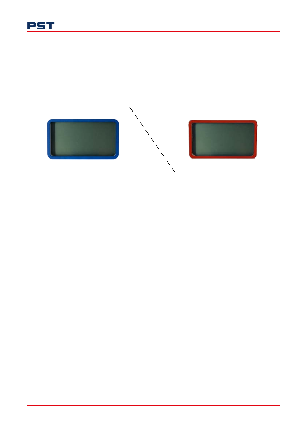
These are battery-powered and certified for safe and hazardous area use indicated by the display. A
blue display outline is for general use, red is for hazardous area as shown below.
GPR-Portable Oxygen Analyzer User Manual
Blue = General purpose, safe area use ONLY
Figure 1. Safe area and hazardous area displays
1.3 Applications
• Monitoring inertization and blanketing gases for the storage or transport of hydrocarbons
• Monitoring natural gas quality
• Monitoring oxygen in pharmaceutical reactors and centrifuges
• Monitoring gas quality in processes: steel production, heat-treatment furnaces, solder re-flow
ovens
• Monitoring pure gas quality on feed gases: the beverage industry, food packaging, N2 generators.
1.4 Sensors
Our maintenance-free electrochemical sensors are galvanic cells capable of superior performance,
accuracy and stability; designed to be unaffected by the presence of background gases. As a
consumptive sensor type, it is disposable and requires only periodic calibrations.
Red = Certified for hazardous area use
Operational life is typically up to 18 months however, replacement frequency is dependent on the
individual application.
If contaminants are present in the sample gas, the sensor can be affected, and the validity of the
measurement impacted. Please ensure that the sensor is protected, and any contamination is
prevented from reaching the analyzer’s pipework and the sensor.
Consult the PST sales team about our cost-effective standard sample conditioning systems.
2 ProcessSensing.com
Page 9

GPR-Portable Oxygen Analyzer User Manual
Table 1: Available sensor types
Analyzer Model
Model Number
Recommended O2 Measurement
Range
Minimum Range
Sensitivity
For full sensor technical specifications, please refer to "Appendix A - Technical Specifications" on
page 41.
1.4.1 GPR-12-333
Our standard ppm sensor can be used to measure O2 in a wide variety of gases.
Specific sensor selection should be given when the background gases are helium (He), hydrogen (H
or greater than 0.5 % carbon dioxide (CO2).
1.4.2 GPR-11-60-4
The 0.25 % sensor can be used to measure O2 in a wide variety of gases.
GPR-1100 GPR-1200 GPR-2000
GPR-12-333
XLT-12-333
GPR-12-333-H
0...1000 ppm
0...10 ppm
0.01 ppm
V
V
V
GPR-12-333
XLT-12-333
GPR-12-333-H
0...1000 ppm
0...10 ppm
0.01 ppm
V
V
V
GPR-11-60-4
XLT-11-24-4
0...25 %
0...1 %
0.005 %
)
2
Specific sensor selection should be given when the background gases greater than 0.5 % CO2.
1.4.3 XLT-12-333
For measurement applications with ppm levels of O2 in a background gas containing more than 0.5 %
, the specially designed XLT sensor should be selected.
CO
2
With most standard electrochemical sensors, an alkaline electrolyte is used; this is neutralized over
time when exposed to acid gases, such as CO
sensor with a special electrolyte formula, which maintains functionality in temperatures as low as
-10 °C (14 °F).
1.4.4 XLT-11-24-4
Our 0...25 % sensor is for measurement applications with % levels of O2 in a background gas
containing more than 0.5 % CO2.
With most standard electrochemical sensors, an alkaline electrolyte is used; this is neutralized over
time when exposed to acid gases, such as CO
with a special electrolyte formula, which maintains functionality in temperatures as low as -10 °C
(14 °F).
1.4.5 -H suffix
. To combat this, PST has developed the XLT
2
. To combat this, PST has developed the XLT sensor
2
For measurement applications with ppm levels of O2 in a background gas of either H2 or He, the
specially design -H sensor should be selected for optimum performance.
NOTE: Calibration is required each time your sensor is replaced. Ideally, your sensor should be
replaced before reaching the end of its operational life.
ProcessSensing.com 3
Page 10

1.5 Further general considerations
When your portable analyzer is used with or in other equipment please consider the following:
• The analyzer should not be submerged in any liquid. Care should be taken to ensure liquids are not
spilled and objects do not fall into the unit.
• Avoid force when using connectors, switches and knobs. Before moving your analyzer, be sure to
disconnect the wiring/power cord and any cables connected to the output terminals.
• Ensure the sensor selected and supplied is suitable for the gas composition to which it will be
presented; if in doubt, review the application and consult the PST Factory before initiating the
installation.
• The products covered should be evaluated to the environmental conditions as defined by the
standard up to 2,000 m (6,500 ft) altitude and within the temperature range applicable to your
sensor; refer to "Appendix A - Technical Specifications" for details.
• The products covered by this manual should be installed using the manufacturer’s instructions.
• Only the sensor provided by the manufacturer is to be used with the analyzer.
• In natural gas applications such as extraction and transmission, a low voltage current is applied to
the pipeline itself to inhibit corrosion of the pipeline. As a result, electronic devices connected to
the pipeline can be affected unless they are adequately grounded.
GPR-Portable Oxygen Analyzer User Manual
1.5.1 Conditions of use in hazardous areas
NOTE: Always ensure the power is switched off prior to accessing the Ex enclosure for any purpose
other than normal operation, or prior to disconnecting any cables.
Only analyzers marked and certified for use in hazardous areas (identified with a red display outline)
should be used in hazardous areas.
General purpose analyzers (with blue display outlines) are for safe area use only. See "1.2 Models" on
page 2 for reference.
Using a general purpose analyzer in a hazardous area could lead to
injury to personnel.
Refer to "Appendix B - Hazardous Area Certification" on page 42 for certification details.
4 ProcessSensing.com
Page 11

GPR-Portable Oxygen Analyzer User Manual
1.6 Safety approvals and directives
The CE marking indicates the portable
oxygen analyzer conforms to European
health, safety, safety and environmental
protection directives.
This UKCA marking demonstrates the
portable oxygen analyzer complies with
UK designated standards in electric and
electronic engineering and measuring
technology.
The Ex marking indicates the portable
oxygen analyzer conformity to European
Union directive 2014/34/EU (ATEX) and
UK Statutory Instrument 2016 No. 1107
(as amended) (UKEX). It complies with
Intrinsically Safe (I.S) standards for
equipment category 2 when used
following the instructions for safe use in
this user manual. This makes it normally
suitable for use in Zones 1 or 2
hazardous areas.
The MET marking certifies the portable
oxygen analyzer is compliant in North
America and Canada, with the electrical
and hazardous location safety directive.
NOTE: The portable range of analyzers are not tri-rated. These analyzers are built to comply with
ATEX / IECEx / UKEX or cMETus.
The hazardous area compliance rating is shown on the rating plate on the analyzer. Please ensure
your analyzer is compliant with site or location requirements. This user manual details installation,
operation and support for all our portable analyzers for all certifications.
ProcessSensing.com 5
Page 12

2 Installation
NOTE: Installation, operation and maintenance of this equipment should be carried out only by
appropriately trained and suitably qualified technicians in accordance with the instructions in this
user manual, and any applicable standards/certificates associated with the country, industry and
application.
to personnel. In this regard, the manufacturer will not be held liable.
NOTE: The operator may only perform modifications and repairs to the equipment or system with
approval from the manufacturer.
Do not operate damaged equipment. If faults cannot be rectified, the equipment must be taken
out of service and secured against unintentional commissioning.
Before using your portable analyzer, ensure that its specifications are suitable for the process in
which it will be installed.
GPR-Portable Oxygen Analyzer User Manual
Failure to correctly adhere to these instructions may result in injury
6 ProcessSensing.com
Page 13
GPR-Portable Oxygen Analyzer User Manual
2.1 Unpack your analyzer
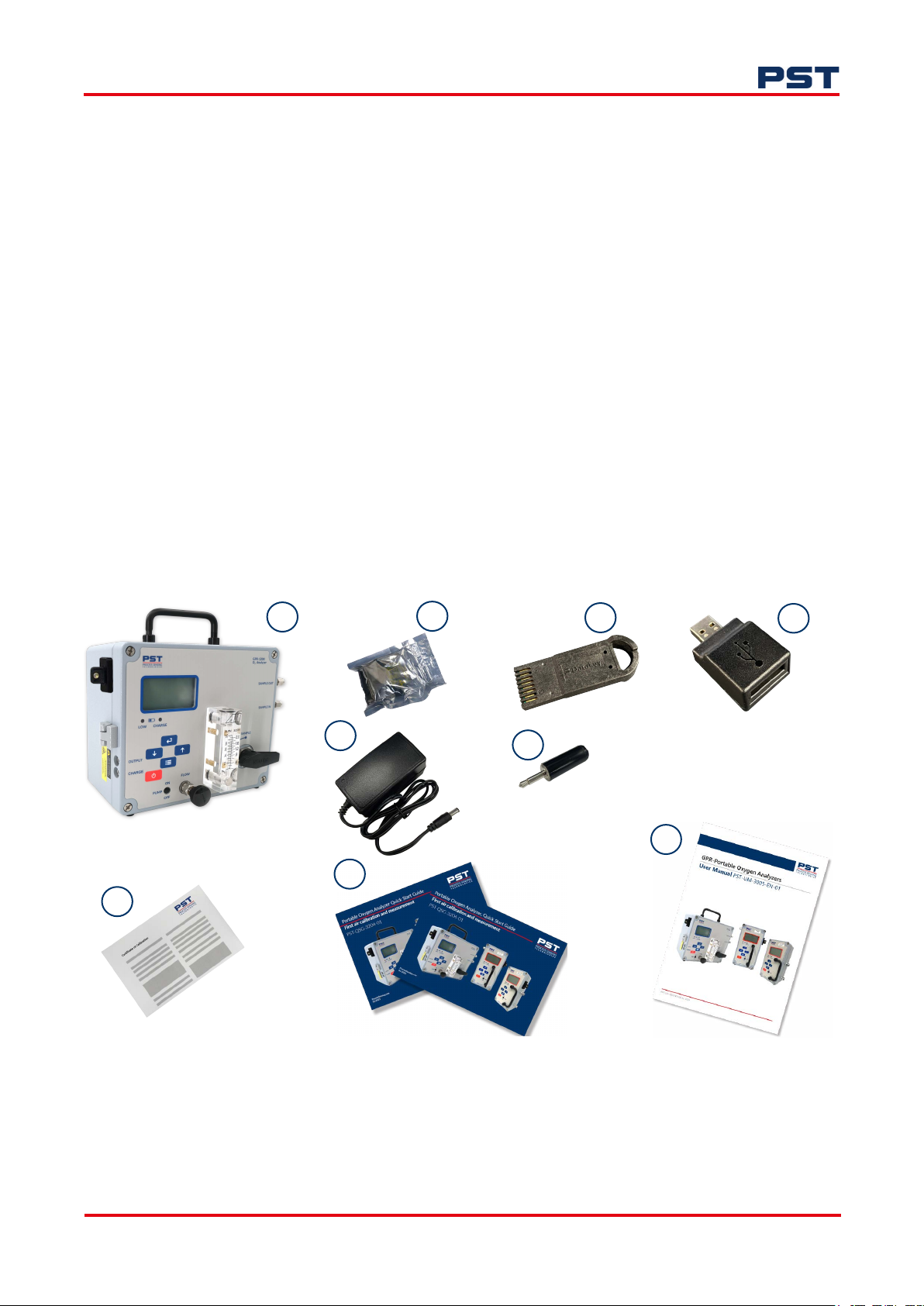
Your portable analyzer pack is comprised of the following equipment (pack contents may vary
depending on your specification):
1. Portable analyzer
2. Sensor in double-foil packet
(only applicable to ppm models without a crossover valve, the sensor is installed in all other
portable analyzers)
3. Memory token
4. Memory token USB adapter
5. Battery charger
6. Output connector
7. PST Factory calibration certificate
8. Quick Start Guides (ref: PST-QSG-3203, span calibration, PST-QSG-3204, air calibration)
9. User Manual, this document (ref: PST-UM-3005) on a USB stick.
GPR-1200 oxygen analyzer pictured
7
1
5
2
3
4
6
9
8
Figure 2. Contents of portable pack
ProcessSensing.com 7
Page 14
2.2 Analyzer features
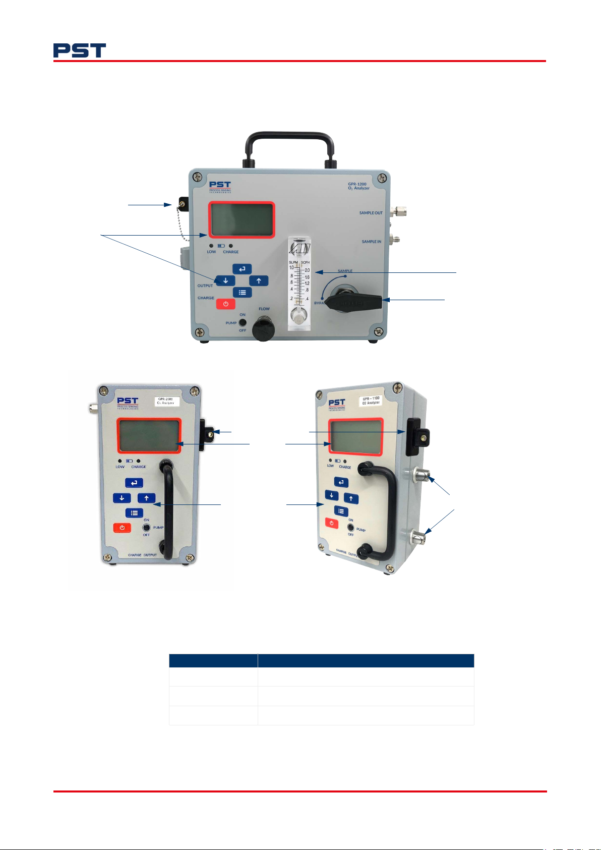
The portable analyzer is a single enclosure, hinged on the left side. The measurements for our portable
analyzers are in "Table 2: Portable analyzer dimensions" below.
Data-logging port
Analyzer interface and display
GPR-1200 analyzer
GPR-Portable Oxygen Analyzer User Manual
Flow meter
Bypass valve
Data logging port
Display
User interface
GPR-2000 analyzer
Figure 3. The portable oxygen analyzer
Table 2: Portable analyzer dimensions
Model Dimensions (L x W x H)
GPR-1100 5.4 x 5.6 x 8.8 “ (137.2 x 142.2 x 223.5 mm)
GPR-1200 10.5 x 6.4 x 10 “ (266.7 x 162.6 x 254 mm)
GPR-2000 5.8 x 5.6 x 8.8 “ (147.3 x 142.2 x 223.5 mm)
Quick disconnect fittings
GPR-1100 analyzer
See "Appendix E - Dimensions" on page 52 for further information.
8 ProcessSensing.com
Page 15

GPR-Portable Oxygen Analyzer User Manual
2.3 Set-up
The analyzer is approved for indoor as well as outdoor use if the ambient temperature remains within
the specified range. Please refer to "Appendix A - Technical Specifications" on page 41.
This portable analyzer configuration is designed to be used on a flat horizontal surface.
The analyzer’s design provides immunity from RFI/EMI by maintaining good conductive contact
between the two halves of the enclosures via a conductive gasket (the smaller enclosure containing
signal processing electronics).
The surfaces contacting the conductive gasket are unpainted. Do not paint these areas. Painting will
negate the RFI/EMI protection.
ProcessSensing.com 9
Page 16
3 Before connecting gas
3.1 Necessary considerations
With standard flow-through configuration, the portable analyzers are designed for positive pressure
samples and require connections for incoming sample and outgoing vent lines.
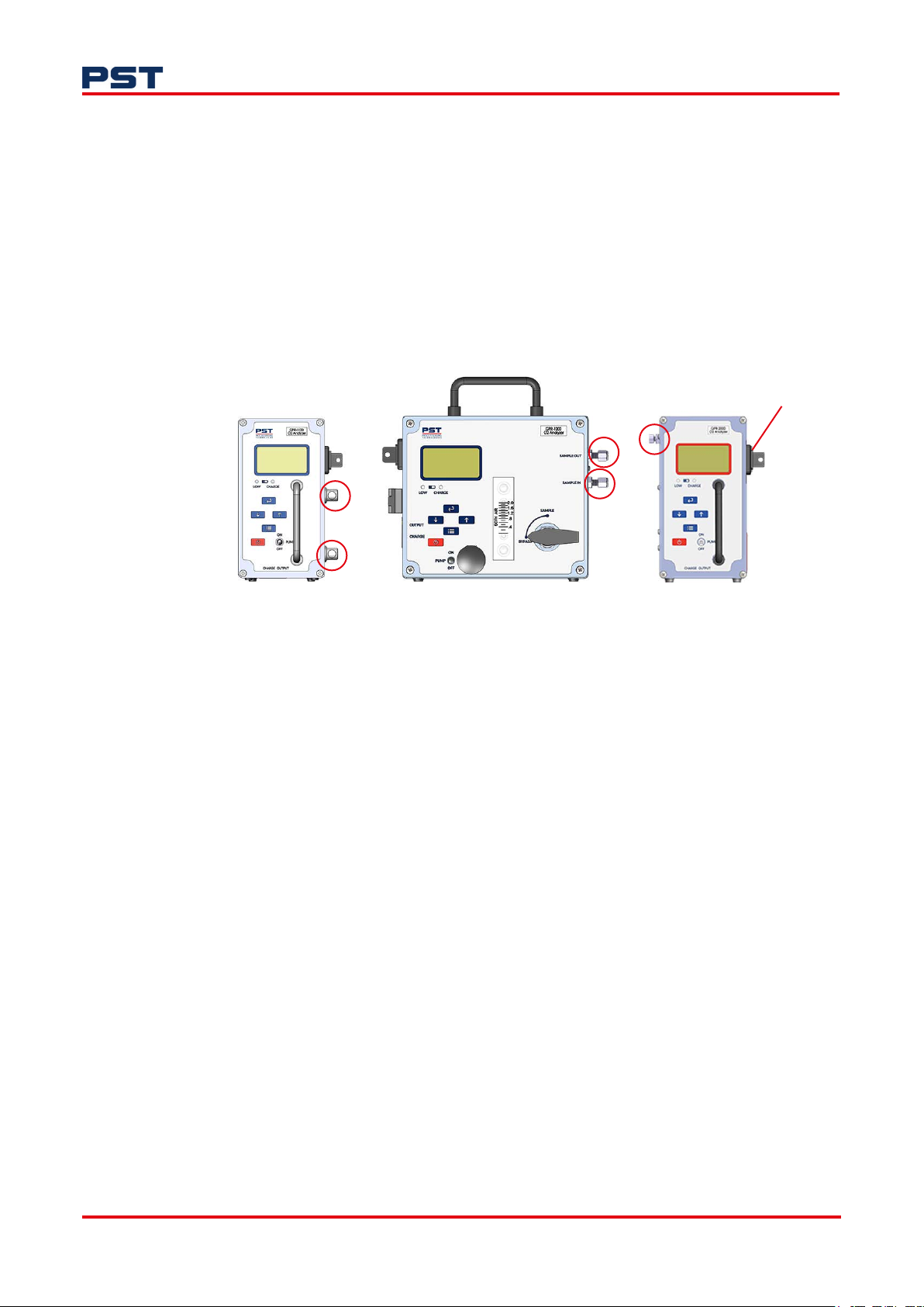
Your analyzer is equipped with two gas ports as highlighted in Figure 4. On the GPR-1200 model, the
Sample In and Sample Out ports are labeled. With the GPR-1100 and GPR-2000 models, assign one
of the ports the vent and the other Sample In.
GPR-Portable Oxygen Analyzer User Manual
Vent behind memory
token receptacle
GPR-1100 GPR-2000GPR-1200
Figure 4. Gas ports
The sample inlet and outlet vent gas lines for the GPR-1100 model require 1/8” PTFE / PVDF tubing.
The fittings are self-sealing push-fit fittings.
The sample inlet tubing for ppm portable analyzer models (GPR-1100 and GPR-1200) must be
metallic, preferably stainless steel (SS). The sample vent line may be of SS or hard plastic tubing with
low gas permeability.
PTFE sample inlet tubing is recommended for the GPR-2000 % portable analyzer.
To ensure the best possible operation, a review of the installation is recommended:
a. Sample gas quality
• Is the sensor suitable for gas?
• Is a gas scrubber required?
• Is the sample gas clean and liquid free?
b. Stainless steel tubing (essential for maintaining the integrity of the gas stream for very low ppm
or % level analysis.
NOTE: If operated in potentially contaminated gases, which can interfere with measurement and
reduce the sensor’s life expectancy. Consult PST for recommendations concerning the proper
selection and installation of components.
10 ProcessSensing.com
Page 17

GPR-Portable Oxygen Analyzer User Manual
3.2 Sample gas requirements
All gas analyzers utilizing electrochemical oxygen sensors respond to partial pressure changes in
oxygen. To ensure accurate measurement of the oxygen sample, gas must be presented to the
analyzer at a stable pressure and flow rate.
3.2.1 Inlet pressure
For the analyzers designed to measure oxygen in a flowing gas stream, the inlet sample pressure must
be regulated in the range 5...30 psig (0.34...2 barg).
3.2.2 Outlet pressure
It is recommended that the sample is be vented to atmospheric pressure or into a flare at atmospheric
pressure. If this is not possible, it should be vented to a pressure that is less than the inlet pressure to
allow the sample gas to flow through the sensor housing.
NOTE: The sensor may be used at a slightly positive pressure (e.g., when sample is vented to a
common exhaust where the pressure might be higher than 1 atmosphere). However, the pressure at
the sensor must remain constant at all times including during the span calibration. This may be
accomplished by using a back-pressure regulator on the vent line of the analyzer.
If assistance is required to configure a measurement at a positive pressure, please contact PST with
full application details for a review.
A sudden change in pressure at the sensor may result in the sensor electrolyte leakage.
ProcessSensing.com 11
Page 18

4 Connect your gas
After reading "3 Before connecting gas" on page 10, follow the procedure below specific to your portable analyzer to connect your gas.
Do not place your finger over the vent (it pressurizes the sensor) to test the flow indicator when
gas is flowing to the sensor. Removing your finger (the restriction) generates a vacuum on the
sensor and may damage the sensor, voiding the sensor warranty.
See Figure 4 on page 10 for port designation
GPR-1100
NOTE: The GPR-1100 analyzer is equipped with quick-disconnect fittings.
1. To ensure gas is venting to atmosphere, connect the vent line to a port.
2. Set the sample gas pressure between 5 and 30 psig (0.34...2 barg).
3. Set your flow rate to 1...2 SCFH (0.5...1 LPM) before connecting gas.
GPR-Portable Oxygen Analyzer User Manual
4. Connect your process gas line to the other port and allow gas to flow for 2...3 minutes to purge
the system.
Your analyzer is now ready for operation.
GPR-1200
NOTE: The GPR-1200 analyzer is equipped with a bypass valve. Ensure it is in the Bypass position
before connection gas.
1. With the bypass valve in the Bypass position, connect your gas line to the Sample In port.
2. Set the sample gas pressure between 5 and 30 psig (0.34...2 barg).
3. Set your flow rate to 1...2 SCFH (0.5...1 LPM) and allow gas to flow for 2...3 minutes to purge the
bypass valve before connecting gas.
Your analyzer is now ready for operation.
GPR-2000
1. Set your flow rate to 1...2 SCFH (0.5...1 LPM).
2. Connect your process gas line to the port using the fitting provided.
3. Start the flow of gas and allow it to flow for 2...3 minutes.
Your analyzer is now ready for operation.
Span calibration gas ports are offered as part of the optional sample systems.
NOTE: If the analyzer is equipped with an optional H₂S scrubber, sample inlet pressure must not
exceed 30 psig (2 barg).
12 ProcessSensing.com
Page 19

GPR-Portable Oxygen Analyzer User Manual
4.1 Calibration gases
NOTE: It is recommended that you use certified zero and span gases for calibration to ensure the
best measurement readings.
Cylinders of the appropriate certified zero and span gases should be made available for verification of
the analyzer’s performance. Calibration gases will need to be set to the same input pressure and flow
rate as the sample gas to ensure calibration integrity.
4.2 Prepare your zero/span gas
Avoid contamination of the zero/span gas cylinder when connecting the pressure regulator. Bleed the
air-filled regulator for a couple of minutes before closing the vent valve of the pressure regulator
(faster and more reliable method of purging the regulator than simply allowing the zero/span gas to
flow through the regulator and the span gas line).
The following components/tools are required to set up a zero/span gas cylinder:
a. Certified zero/span gas cylinder with an oxygen concentration, balance nitrogen, of
approximately 80 % of the full scale range above the intended measuring range.
b. A pressure regulator to enable reduction of gas pressure to between 5 and 30 psig (0.34 and 2
barg).
c. A flow meter (for use only if the analyzer is not equipped with one) to set the flow rate between
1 and 2 SCFH (0.5...1 LPM.
d. Suitable fittings and 1/8” diameter metal tubing to connect the regulator to the inlet of the
analyzer.
Ensure your zero/span gas cylinder valve is closed, then:
1. Install the regulator on the cylinder using good practice.
2. Open the regulator’s exit valve and partially open the pressure regulator’s control knob.
3. Slightly open the cylinder valve.
4. Loosen the nut connecting the regulator to the cylinder and bleed the pressure regulator.
5. Re-tighten the nut connecting the regulator to the cylinder.
6. Adjust the regulator exit valve and slowly bleed the pressure regulator.
7. Open the cylinder valve completely.
8. Set the output pressure between 5 and 30 psig (0.34 and 2 barg) using the pressure regulator’s
control knob.
Do not exceed the recommended pressure. Excessive pressure will make flow adjustment more
difficult.
ProcessSensing.com 13
Page 20

5 Disconnect your gas
Follow the procedure below that is applicable to your portable oxygen analyzer model to disconnect
your gas.
GPR-1100
1. Disconnect your span gas line using the quick disconnect fitting.
2. Stop the flow of gas.
3. Now disconnect the gas line venting to atmosphere using the quick disconnect fitting.
GPR-1200
1. Turn the Bypass Valve to the Bypass position then stop the flow of gas.
2. Disconnect your span gas lines from the Sample In and Sample Out ports.
GPR-2000
GPR-Portable Oxygen Analyzer User Manual
1. Stop the flow of gas.
2. Disconnect the sample gas line by loosening the fitting.
14 ProcessSensing.com
Page 21
GPR-Portable Oxygen Analyzer User Manual
6 Install your sensor
NOTE: Please read through this procedure and "3 Before connecting gas" on page 10 before
attempting to install your sensor.
Your portable oxygen analyzer is equipped with stainless steel sensor housing. This housing offers
ease of replacement of sensor whilst preventing any leakage into the system. The two sections of the
sensor are held together by a metal clamp secured in place by an easy to access bolt.
The integrity of the sensor housing has been tested at the PST Factory prior to shipment.
The analyzer must be calibrated once the installation has been completed and periodically thereafter.
6.1 GPR-1100 and GPR-1200
To install or replace an oxygen sensor:
1. Press to switch on your portable analyzer.
2. Using a screwdriver, remove the four screws to open the front of the enclosure.
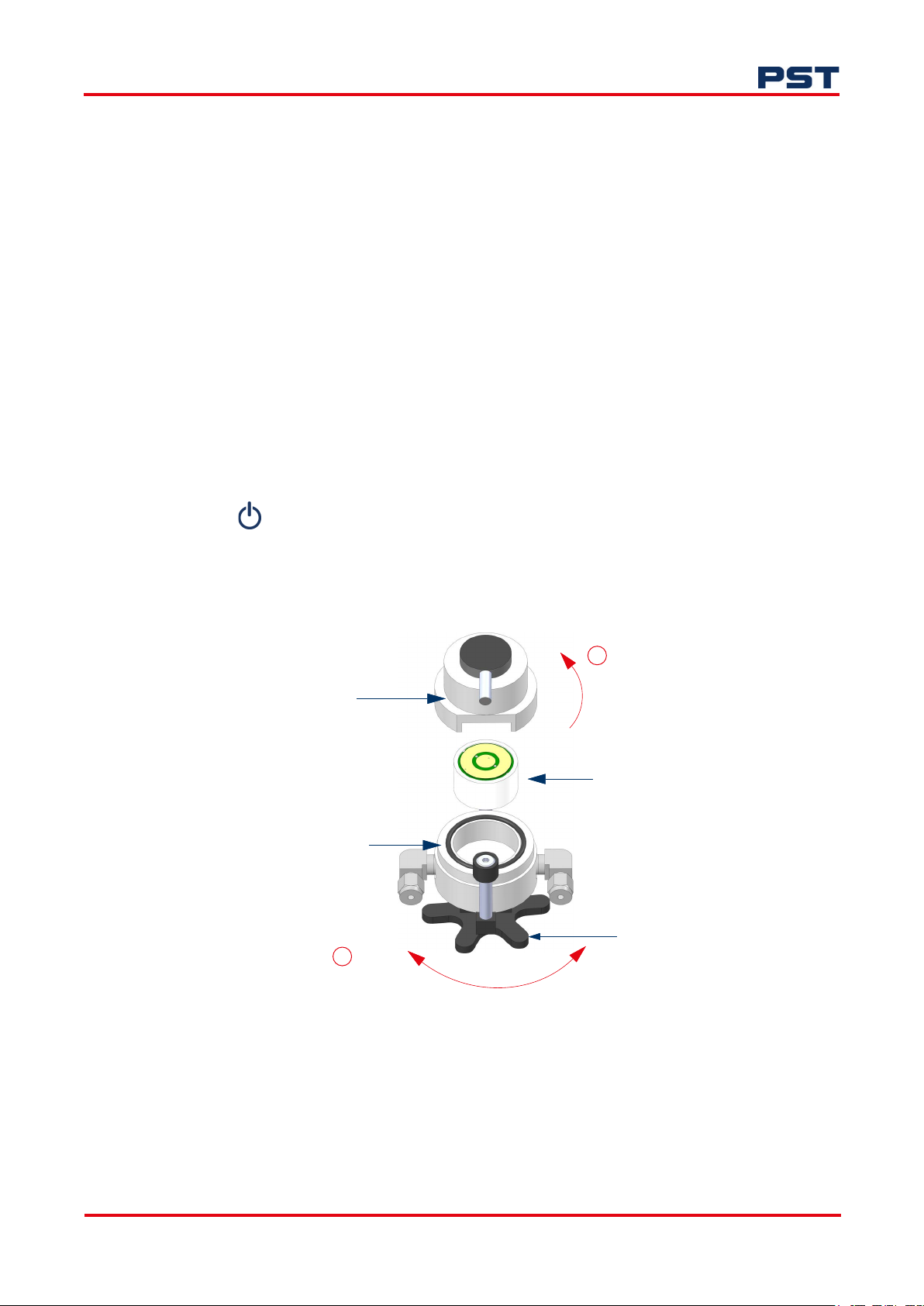
3. Open the sensor housing (refer to Figure 5 below for guidance).
a
Top sensor housing
Bottom sensor housing
b
Loosen Tighten
O
90
Sensor
Star wheel
Figure 5. Installing and uninstalling your sensor (GPR-1100 and GPR-1200)
4. Loosen the star wheel then disengage the top sensor housing by turning it 90° counter-clockwise.
5. If replacing your sensor, remove the old sensor from the sensor housing, otherwise continue to
the next step.
ProcessSensing.com 15
Page 22

GPR-Portable Oxygen Analyzer User Manual
6. Remove the sensor from its packaging, remove the shorting flags and immediately place in the
top sensor housing with the gold contact plate facing towards two gold contact pins in the top
sensor housing as shown in Figure 6.
Figure 6. Aligning your sensor
NOTE: You may perform a zero and span calibration or an air calibration to confirm that the sensor
output is within the recommended limits. See " Zero and span vs span calibration" on page 23 for
guidance.
7. Secure it with the star wheel at the bottom of the housing assembly (refer to ‘b’ in Figure 5 on
page 15).
8. Quickly close your analyzer and connect your process sample gas or zero oxygen gas
immediately, following the procedure in "4 Connect your gas" on page 12.
16 ProcessSensing.com
Page 23
GPR-Portable Oxygen Analyzer User Manual
6.2 GPR-2000
To install or replace an oxygen sensor:
1. Press to switch on your portable analyzer.
2. Using a screwdriver, remove the four screws to open the front of the enclosure.
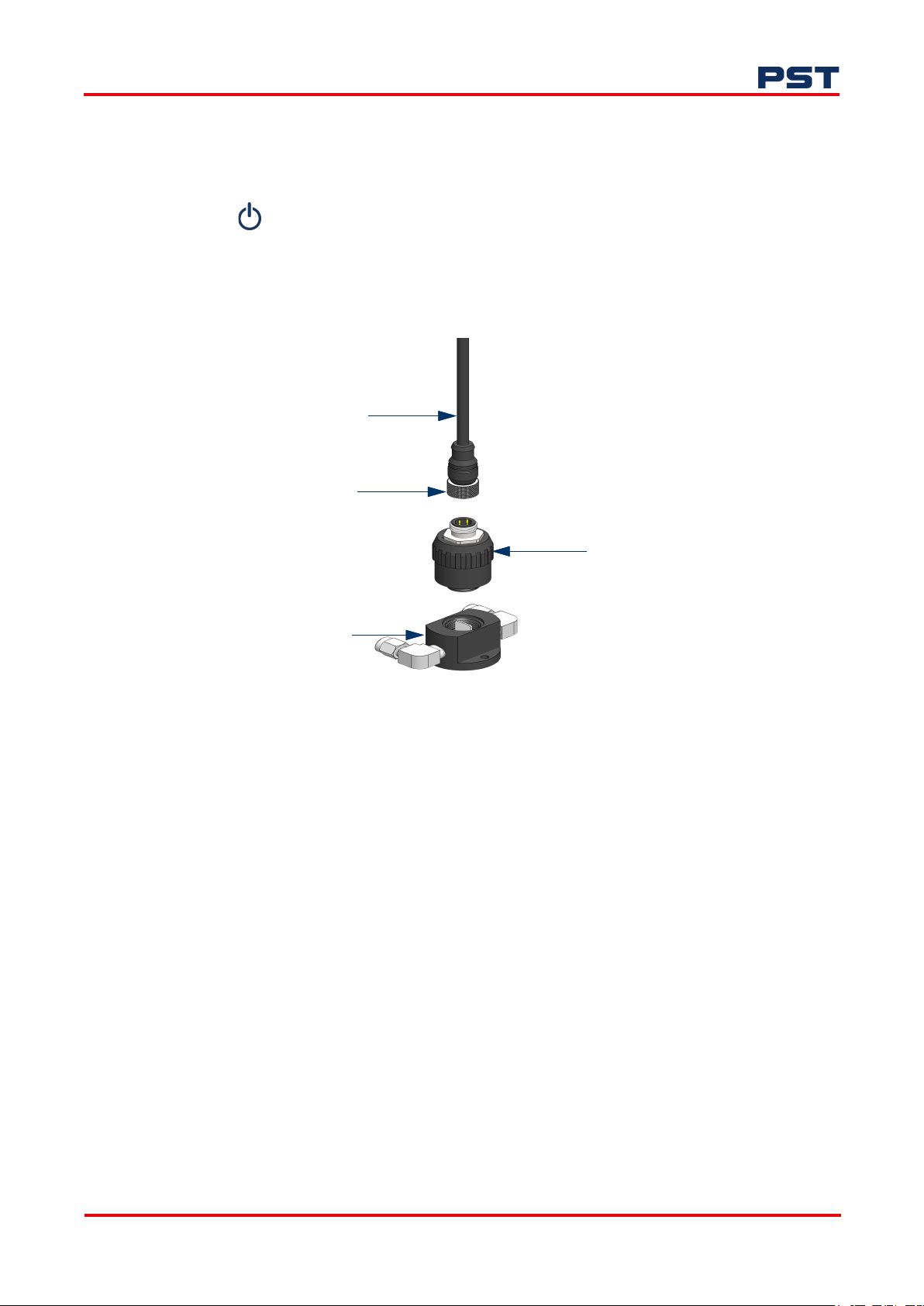
3. If replacing the sensor, disconnect the sensor cable from the old sensor by turning the lock nut
counter-clockwise, otherwise continue to step 5. Refer to Figure 7 below.
Sensor cable
Lock nut
Sensor
Sensor base
Figure 7. Installing and uninstalling your sensor (GPR-2000)
4. Remove the sensor from its base by unscrewing counter-clockwise.
5. Remove the new sensor from its packaging and screw it into the sensor base.
6. Reconnect the sensor cable by plugging it into the sensor and turning the lock nut clockwise.
7. Replace the enclosure door, securing it with the four screws.
ProcessSensing.com 17
Page 24
7 Operation
This section details the best practice operation for a correctly installed analyzer. Please refer to "2
Installation" on page 6 for analyzer installation guidance and gas connection.
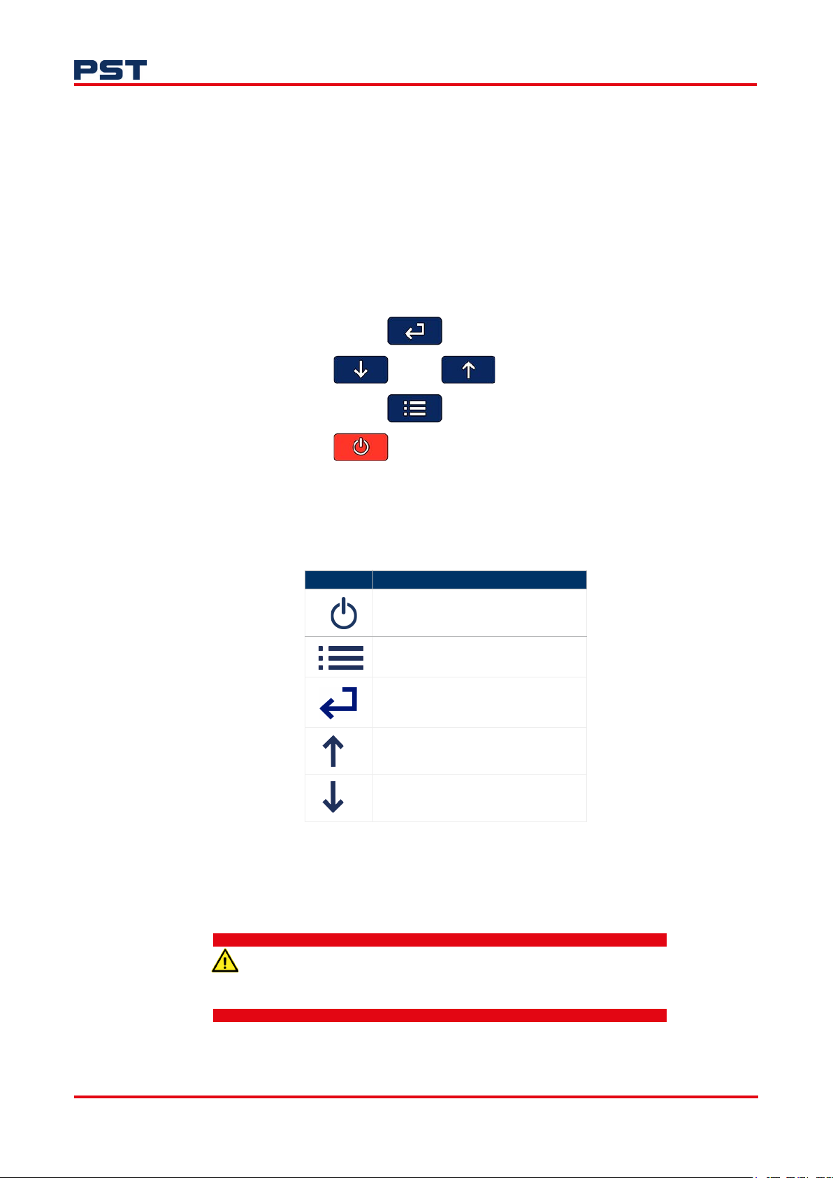
7.1 User interface
The portable analyzer has a 3.5-inch LCD display and a five-key keypad interface.
GPR-Portable Oxygen Analyzer User Manual
Figure 8. Portable analyzer user interface
The interface keys can be used as identified in the table below:
Table 3: Interface key functions
Key Function
On/off
Menu open/close
Enter
Next (increment)
Previous (decrement)
Only analyzers marked and certified for use in hazardous areas (identified with a red display outline)
should be used in hazardous areas.
General purpose analyzers (with a blue display outline) are for safe area use only. See "1.2 Models" on
page 2 for reference.
Using a general purpose analyzer in a hazardous area could lead to
injury to personnel.
18 ProcessSensing.com
Page 25
GPR-Portable Oxygen Analyzer User Manual
7.2 Initial start-up and self-test
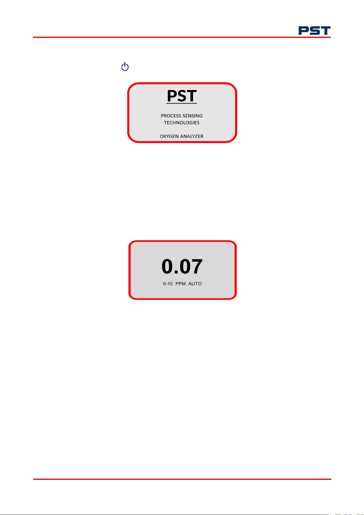
Once you press the button, the analyzer will immediately start up. The digital display responds
instantaneously and will display an initial start-up screen:
Figure 9. GPR-series analyzer start-up screen
After self-diagnostic tests, the analyzer switches to sampling mode and displays the oxygen reading
from the sensor (larger size numeric value) and the measurement range (small size font with units).
Auto indicates that the analyzer is in AUTO mode. In this mode, the measured value affects the range,
which will automatically adjust to the next higher level. See Range (page 21) in the Main Menu to
select.
If the Auto is not selected, the range display will not show Auto. An example of a sampling mode
screen is shown below in Figure 10.
Figure 10. Measurement mode display
ProcessSensing.com 19
Page 26
7.3 Menus
NOTE: Available menu options and sequences will vary between analyzer model and sensor type.
7.3.1 Main Menu and interface keys
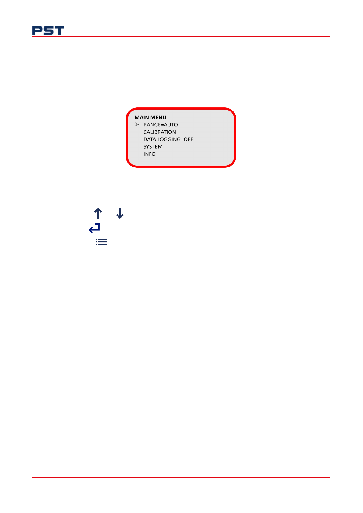
To access the Main Menu, press the Menu key and the following Main Menu display will appear:
Figure 11. Main menu display
This screen shows the menu options available.
GPR-Portable Oxygen Analyzer User Manual
• Use the and keys to move the cursor to the desired menu
• Press to access the sub menu
• Use the key to return to the previous screen.
Range
Configure analyzer measurement range (see "7.3.2 Range selection" on page 21).
Calibration
Perform zero or span calibration functions (see " Zero and span vs span calibration" on page 23).
Data logging
Configure on board logging function (see "7.3.4 Data logging" on page 26).
System
Configure system-level settings (see "7.3.5 System" on page 28).
Info
View analyzer information (see "7.3.6 Info" on page 30).
20 ProcessSensing.com
Page 27

GPR-Portable Oxygen Analyzer User Manual
7.3.2 Range selection
Within the Range menu, you can select 6 options. The range is linked to the display and the 4...20 mA
analog output of the analyzer.
Figure 12. Portable analyzer Range and Default Range displays
NOTE: For trace oxygen analyzers, the range 0...25 % is for air calibration purposes only. It is not a
measurement range of the analyzer (see " Zero and span vs span calibration" on page 23 for
calibration). Using this range will significantly shorten the sensor life.
Range menu options
In the Range menu:
1. Use and to move the cursor to the desired range option.
2. Once the cursor is pointing to your chosen range, press to select the range.
Selecting a range will cause the Auto option to change to Fixed. To select Auto, use to move
the cursor to Fixed, then press to toggle between Auto and Fixed.
Auto
Selecting Auto will enable automatic adjustment of your measurement range depending on the
oxygen levels detected by your oxygen sensor. For example, a 0...10 ppm range will change to
0...100 ppm if the measured oxygen value is higher than 10 ppm.
Default Range
This option will prevent incorrect range-setting if multiple users have access to the analyzer.
If the analyzer range has been changed, for instance for the purpose of checks or maintenance,
and a default range has been pre-set, the analyzer will automatically return to the default range
after 30 minutes of inactivity.
Def Range allows you to set the default range for the analyzer. Within this sub-menu, all
standard ranges or Auto mode can be selected.
ProcessSensing.com 21
Page 28

It is recommended that you set your preferred default range for the analyzer.
Measurements outside manual range
If the oxygen reading goes above the manual or auto range maximum value, the values will be
displayed up to 10% above the maximum range. Beyond this, an OVER RANGE warning will be
displayed.
7.3.3 Analyzer calibration
GPR-Portable Oxygen Analyzer User Manual
Figure 13. Default Range display
All electrochemical sensor-based analyzers require periodic calibration. The electrochemical sensor
signal will remain relatively constant throughout its useful life, however, some components in a gas
stream, e.g. sulfides, can adversely affect the sensor causing changes in sensitivity with time. As such,
regular calibration is recommended to ensure accuracy and ascertain the integrity of the sensor (e.g.
weekly intervals to a 3-month maximum).
It is the user’s responsibility to determine the frequency of calibration or verification. This should take
into account the significance of the measurements that are being performed.
Always use good calibration practices.
• Calibrate the analyzer at or close to the temperature and pressure of the sample gas
• Use known reference gases or fresh air
• Allow suitable stability time especially when making significant changes in measurement value (e.g.
20.9 % to 0.0 %). See the table below.
Table 4: Example stability times
Condition example Typical stability time
<1 % to air (20.9 %) <3 minutes
Air (20.9 %) to 0.1% <30 seconds
Air (20.9 %) to 0.01% <2 minutes
2 minute air exposure to 10 ppm 60 minutes
Set sensor serial number
Updating the sensor serial number is critical for the calibration process.
When replacing O
digit sensor serial number, enter the Calibration menu.
22 ProcessSensing.com
sensors it is important to update the sensor serial number. To view the current 9-
2
Page 29
GPR-Portable Oxygen Analyzer User Manual
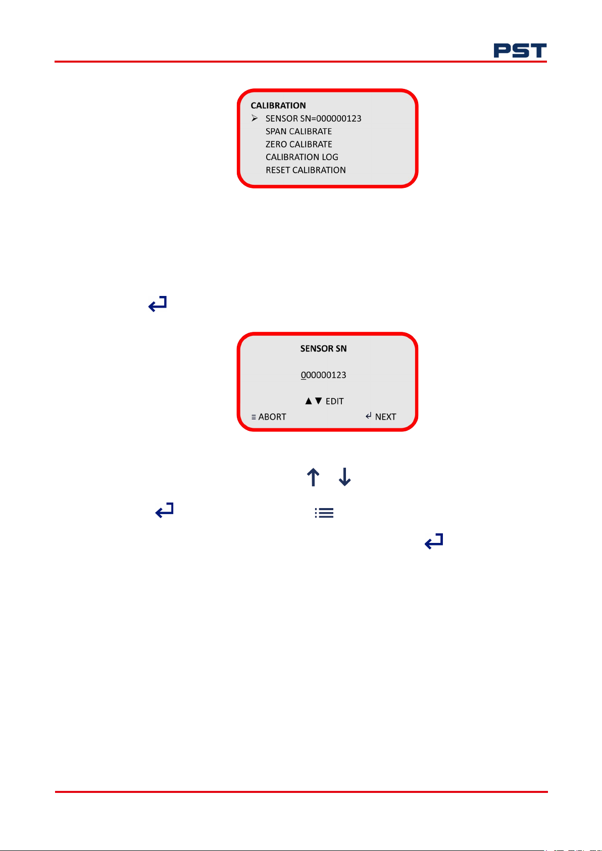
The sensor serial number can be seen in the menu as shown below:
NOTE: Entering a new serial number will reset calibration (span and zero) to default values and
erase the Calibration Log.
To change the sensor serial number:
1. Use to select Sensor SN=00000000.
The display will change as shown below in Figure 15.
Figure 14. Calibration display
Figure 15. Sensor serial number display
2. Enter your sensor serial number by using or to edit the value.
3. Press to progress to the next digit or to move to the previous digit.
4. When you have entered your sensor serial number’s last digit, press to Accept the new
serial number.
Zero and span vs span calibration
Electrochemical oxygen sensors generate an electrical current that is linear or proportional to the
oxygen concentration in a sample gas. In the absence of oxygen the sensor exhibits an absolute zero,
i.e. the sensor does not generate a current output in the absence of oxygen. Given the properties of
linearity and an absolute zero, a single point calibration is possible.
Zero calibration is required for any measurement below the analyzer’s lowest measurement range.
Span calibration is required routinely for accurate measurements of oxygen.
NOTE: Zero calibration should always be carried out before a span calibration.
ProcessSensing.com 23
Page 30

GPR-Portable Oxygen Analyzer User Manual
Zero calibration
The zero calibration adjustments are limited to 30 % of the most sensitive range. All analyzers are QCtested to confirm the zero calibration. Should you observe a zero calibration error more than 30 % of
the lowest range, we recommend first:
• Check the sample system for any possible leaks
• Confirm the integrity of the zero gas
• Ensure the analyzer has been given enough time to stabilize on the zero gas
• Ensure CLIP = OFF. Refer to " Clipping" on page 29 for information.
If adequate time is not allowed for the analyzer to establish the true baseline and a ZERO calibration
is performed, the analyzer will likely display a negative reading in the sample mode when exposed to
zero gas. If a negative reading is observed, we recommend repeating the ZERO calibration.
To perform a zero calibration:
1. Enter the Calibration menu and select Zero Calibrate.
The analyzer will switch to Zero Cal mode and display the live readings.
Figure 16. Zero calibration display
2. Once gas readings are stable you can Accept or Abort the calibration.
The calibration will Pass or Fail and the analyzer will return to normal operation at the configured
range.
During calibration ensure stability of readings, secure gas connections and supply of suitable
reference gas.
Span calibration
To perform a Span Calibration, enter the Calibration menu and select Span Calibration.
Figure 17. Span gas display
In the sub-menu, set the Span Gas value. If using certified cylinder gas, this can be found on the
certificate that was supplied with the cylinder:
24 ProcessSensing.com
Page 31
GPR-Portable Oxygen Analyzer User Manual
1. Use to progress to the next digit or to move to the previous digit; use and to
edit the values.
2. Now select the calibration gas units (% or ppm).
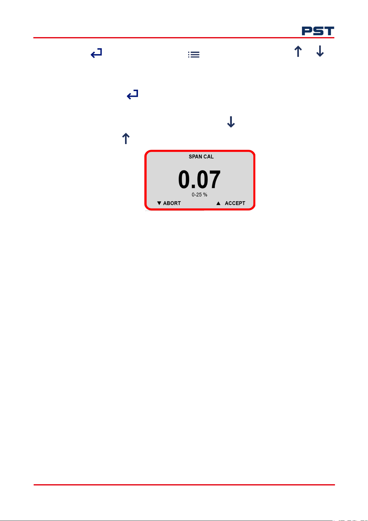
3. When you press , the analyzer will switch to the appropriate range and display the live
readings.
NOTE: When a Span or Zero Cal starts, only "Abort" when is shown until the reading is stable,
then "Accept" when appears.
Figure 18. Span calibration display
During calibration ensure stability of readings, secure gas connections and supply of suitable
reference gas.
Once gas readings are stable you can Accept or Abort the calibration. The calibration will Pass or Fail
and the analyzer will return to normal operation at the configured range.
If a first span calibration receives a Pass this indicates the measurement was within acceptable limits.
Subsequent span calibrations will pass when output is between 70 % and 115 % of the first span
calibration.
A first span calibration will Fail if the sensor is weak. This is indicated with a measurement outside of
the acceptable range. An alert in the form of a persistently blinking error message on the analyzer’s
Home screen will indicate a weak sensor.
Subsequent span calibrations will fail if the output is lower than 80 % of the first span calibration, if it
drops by 30 % of the first span calibration, or if it increases above the first span calibration by 15 %.
This could be caused by a bad first calibration or a bad sensor.
If your span calibration fails, use the Reset Calibration function.
NOTE: If using a ppm sensor we do not recommend exposure of the sensor to ambient air as it will
significantly degrade the sensor life.
ProcessSensing.com 25
Page 32
GPR-Portable Oxygen Analyzer User Manual
Calibration log
The Cal Log shows a summary of events on the analyzer. A total 256 records can be recorded.
Details included are shown below;
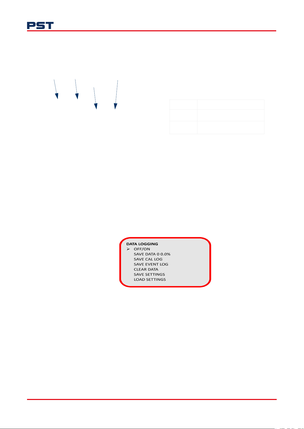
Date Cal Type Pass/Fail
Correction Value
01/01/23 RST ZRO = Zero calibration
01/01/23 SPN -0.05 P SPN = Span calibration
01/01/23 ZRO -1.00 F RST = Reset calibration to factory
calibration
NOTE: The correction value does not relate to actual readings it is a proportional value. This value
can be used by the PST Factory for diagnostics.
Reset calibration
This function will reset both span and zero calibration information to default values. It will not clear
the Calibration Log.
7.3.4 Data logging
The analyzer has an on board logging function. The logging rate is 60 seconds and capacity is 30 days.
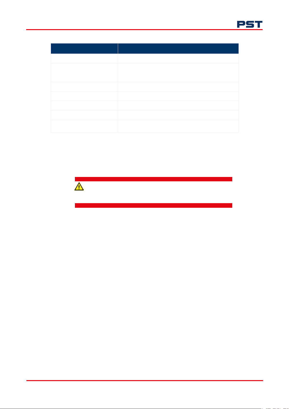
Logging is enabled via the Data Logging menu:
See "Table 5: Data logging functions" on page 27 for the functions of each menu item.
Figure 19. Data logging display
26 ProcessSensing.com
Page 33
GPR-Portable Oxygen Analyzer User Manual
Table 5: Data logging functions
Function Action
Off/On Switch the data logger on or off
Save Data 0 0.0% The first figure represents the number of data files stored
Save Cal Log Save the current calibration log (to the memory token)
Save Event Log Save the current event log (to the memory token)
Clear Data Clears all previously logged data (from the internal logger)
Save Settings Logs or backs up current settings (to the memory token)
Load Settings Loads configuration settings from the memory token to the
To enable logging:
1. Switch the first menu item from Off > On.
2. When the analyzer’s 30-day memory is full, logging will automatically stop and an alert will be
shown on the main screen.
The percentage figure represents the amount of memory used
(100 % = 30 days)
analyzer
The memory token must be inserted in the analyzer in a Safe Area
only.
To export data:
1. Insert the memory token into the analyzer.
2. Use the interface buttons to select:
• Save Data to export log files
• Save Cal Log to export the calibration log data
• Save Event Log to export the analyzer event log.
ProcessSensing.com 27
Page 34
GPR-Portable Oxygen Analyzer User Manual
Figure 20. Data logging memory token
Once exported to the memory token, the data can be transfered to a Windows PC via its USB port.
Data stored on the memory token is in .CSV format.
On board data can be cleared using the Clear Data menu item.
Export or import device settings
The Data Logging menu can be used to export your analyzer settings for loading to other analyzers.
To export analyzer settings:
1. Insert the memory token into your analyzer.
2. Select Save Settings using the interface navigation keys.
To import analyzer settings:
1. Insert the memory token with the saved settings file into the analyzer to which you want to load
the settings.
2. Select Load Settings using the interface navigation keys.
7.3.5 System
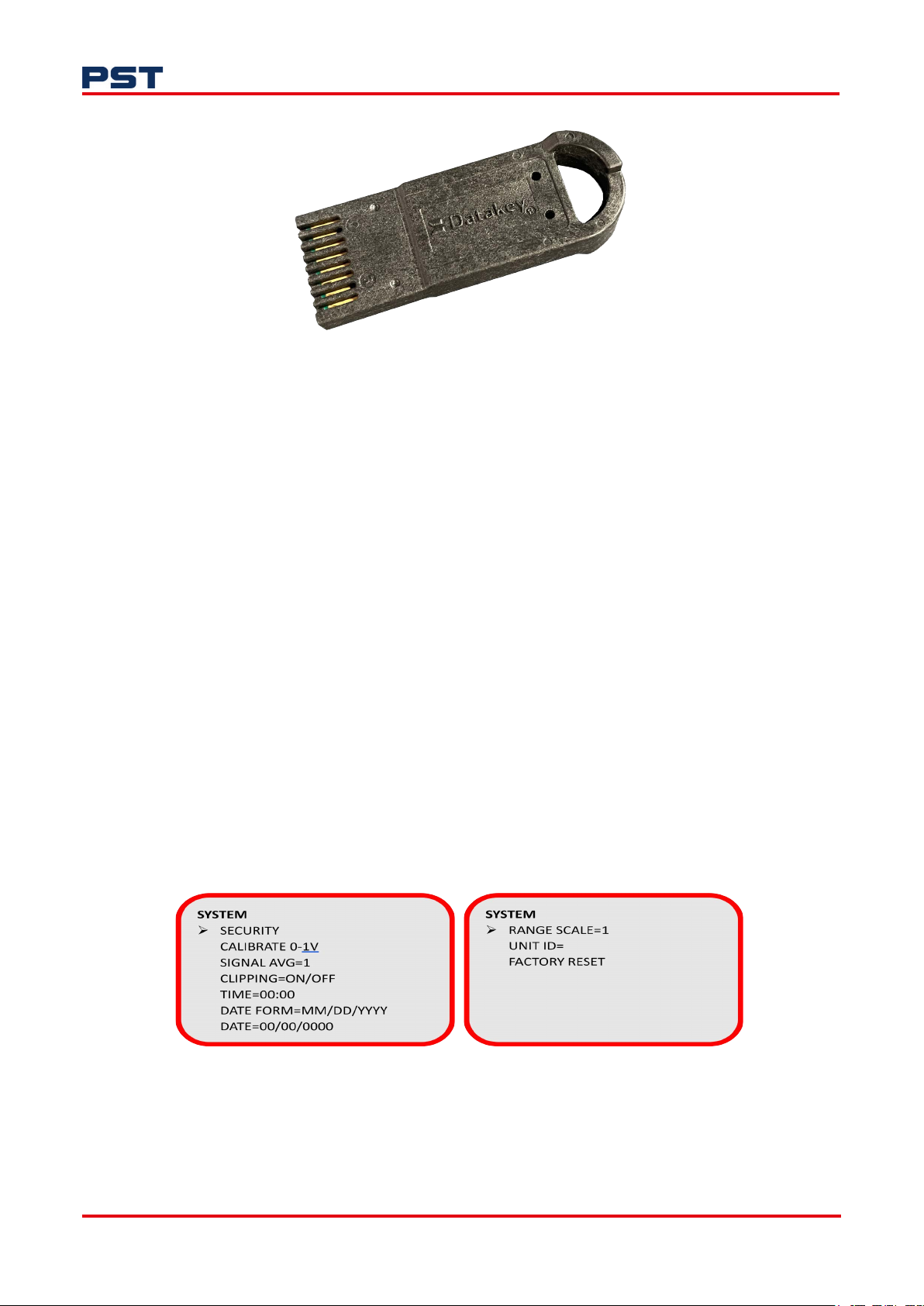
Use the System menu to make the system adjustments shown in Figure 21.
Figure 21. System display
28 ProcessSensing.com
Page 35

GPR-Portable Oxygen Analyzer User Manual
Figure 22. System sub-menu displays
Security
• Enable Screen Lock with a pass code (default code is 0000)
• Set Pass Code > Set the 4-digit pass code
• Enable Auto Lock > Locks the screen after 30 minutes.
Calibrate 0-1 V
This sub-menu ensures alignment between the analyzer and your data acquisition system so that
readings are consistent. Two calibration points - zero and full scale - will offset and scale the output.
1. Use the keypad to adjust the reference corrections for both 4 and 20 mA outputs.
2. Select Accept to apply the adjustments or Abort.
Signal AV - signal average
This function enables the setup of a measurement rolling average. A value between 1...100 readings
can be used in a simple average calculation for the display measurements. Measurements are made at
1 Hz so that a value of 60 will give a 1-minute rolling average.
Higher signal average will help remove measurement instability but will reduce measurement
response.
Clipping
Enabling Clipping will stop the analyzer displaying negative readings below 0 ppmV / 0 %. A negative
reading may occur when:
• Electronics drift or malfunction
• The sensor drifts
• The system’s leak rate changes
• The sensor is bad
• A premature zero calibration is performed (most common)
• There’s pressure change at the sensor.
Time
Sets the on board 24-hour clock for data logging.
ProcessSensing.com 29
Page 36

GPR-Portable Oxygen Analyzer User Manual
Date form
This user-configurable functions enables you to set your date format preference to one of the
following:
mm/dd/yy
dd/mm/yy
yy/mm/dd
Date
Set the on board device date (after a full power cycle the date time will be 00:00 1 Jan 2000.
Range scale
Adjusts the ppm range max value by a multiple (1-5). For example, setting Range Scale to 5 will give
the following Range Options in the Range menu:
• 0-50 ppm
• 0-500 ppm
• 0-5000 ppm
Your analyzer is supplied with a Range scale of 1 as standard. This will generate ranges of:
• 0-10 ppm
• 0-100 ppm
• 0-1000
NOTE: Range scale only applies to the lowest three ranges of group 1 O
Unit ID
Allows an Alpha numeric ID to be given to the analyzer. This value will be stamped on log files and
viewable in the INFO sub-menu.
Factory reset
Reverts all settings to Factory Configuration including security settings, sensor calibration and analog
calibration.
7.3.6 Info
The Info menu displays the device information including:
(10, 100, 1000 ppm O2).
2
Figure 23. Info display
30 ProcessSensing.com
Page 37
GPR-Portable Oxygen Analyzer User Manual
• UNIT ID: User defined (this is left blank for user, usually a location ID or asset number is entered
here)
• ANA SN: Serial number of the analyzer (The 9-digit analyzer serial number is also displayed in log
files)
• PCB SN: Serial number of the circuit board (a 9-digit number)
• FIRM: Firmware part number and revision
• CONFIG: This number refers to your analyzer’s power, gas and Factory group number.
7.4 Recharge your battery
The analyzer is powered by an integrated lead-acid rechargeable battery that is mounted inside the
housing.
A 9 V DC/AC battery charger is supplied with your analyzer. It can enable indefinite operation whilst
the analyzer is plugged in, and continuous operation during the 12-hour charging cycle.
All analyzers, whether General Purpose or Hazardous Area, must
be charged in a Safe Area only.
The analyzer’s charging circuit accepts only 9 V DC from any standard AC 110 V or 220 V adapter
(with positive supply in the center of the female charging jack).
When your analyzer’s battery requires a recharge, a Low LED will light up, indicating there are 72
hours of battery life remaining.
NOTE: The battery must be recharged within the 72-hour window to prevent permanent damage.
To charge your battery:
1. Unless the analyzer is being used while charging, press to turn it off.
2. Plug the 9 V DC adapter supplied with your analyzer to a 110 V or 220 V outlet.
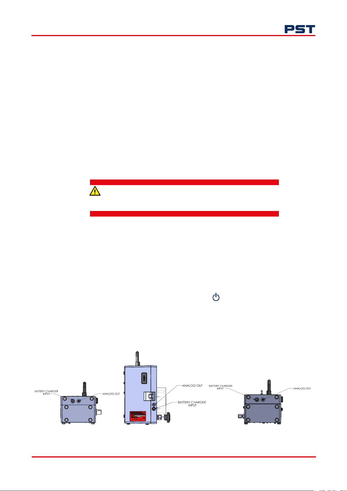
3. Connect the jack to your analyzer’s charging port, which is located at the bottom
as shown in Figure 24
The Charge LED at the front of the analyzer will be illuminated during the charging cycle.
Figure 24. Battery charging input
ProcessSensing.com 31
Page 38

GPR-Portable Oxygen Analyzer User Manual
A single charge will enable you to use your portable analyzer unplugged for 30 days. If your analyzer
is fitted with integrated sampling pumps, the battery life will be 24 hours if used continuously.
32 ProcessSensing.com
Page 39

GPR-Portable Oxygen Analyzer User Manual
8 Maintenance
The portable analyzer will provide reliable and fault-free service with regular maintenance and
calibration.
During periods without use, the sensor should be purged with nitrogen or argon gas to preserve the
sensor life.
• GPR-1100: This model has self-sealing connectors to trap purge gas preserving the sensor
• GPR-1200: This analyzer requires valve operation, to protect the sensor from depletion the valve
must be in the “Bypass” position
• GPR-2000: The % sensor in this analyzer will not deplete with exposure to open air.
Do not attempt to make repairs to the analyzer. This will void the
warranty and may result in electrical shock, injury, or damage. All
servicing should be referred to qualified service personnel.
Some parts of your portable analyzer may require replacement due to normal wear. For a full list of
replaceable parts and item codes, please refer to "Appendix G - Spare Parts" on page 55.
8.1 Replace your sensor
To maintain performance, the sensor in your portable analyzer will require replacement. Sensor life is
application dependent.
When your sensor reaches the end of its serviceable life, calibration can no longer be performed and
the sensor must be replaced.
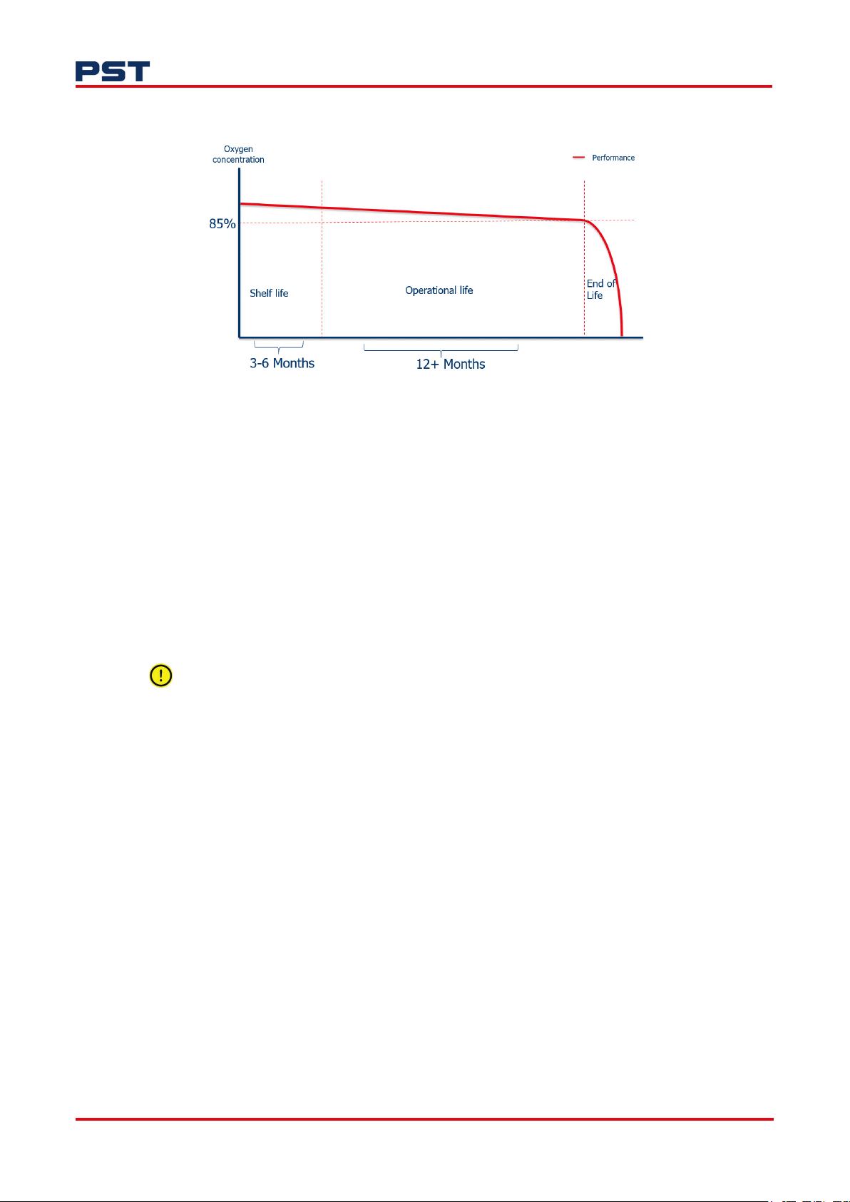
Depending on the application, our EC sensors can last between 12 and 24 months. Sensor life is a
combination of shelf and operational life. Shelf-life is typically 3...6 months when stored in an inert
environment. Factors that affect sensor life include:
• Sample gas contaminations i.e. acid gases and/or moisture
• The oxygen concentration level being measured - the higher the concentration the shorter the
sensor life
• Sample gas temperature - a sample gas that is very dry or has an elevated temperature can lead to
the electrolyte drying out and a shorter sensor life.
ProcessSensing.com 33
Page 40
GPR-Portable Oxygen Analyzer User Manual
Figure 25. Sensor performance chart
A regular program of calibration will mitigate against sudden sensor failure. It is advisable to establish
a program of preventative maintenance to ensure process downtime is kept to a minimum or avoided.
The protective plugs on your sensor should only be removed when your portable analyzer is installed
and ready to begin gas measurement.
Refer to "3 Before connecting gas" on page 10 for the sensor installation procedure.
8.2 Routine cleaning
During sensor replacement, it is recommended that light cleaning of electrical contacts is carried out.
Never use chemical cleaning agents, solvents or high pressure water or steam to clean the
equipment. Do not submerge in water.
To perform routine cleaning:
1. Use a clean cloth that is damp with water to wipe away dust and dirt from the outside of the unit.
2. Dry the analyzer with a clean, dry cloth.
34 ProcessSensing.com
Page 41
GPR-Portable Oxygen Analyzer User Manual
8.3 Routine inspection of sensor housing
The maximum interval between routine inspections should be determined with consideration of the
application and importance of the measurement.
The interval should be reassessed on a regular basis and can be extended and reduced as the process
control requires.
This can be carried out during sensor replacement. To perform routine inspection:
1. Ensure the gas entry and vent ports on the sensor housing are not obstructed.
2. Inspect the sensor housing seal and replace it if damage is visible.
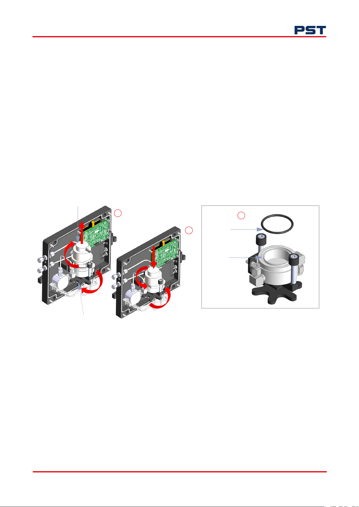
To replace the sensor housing seal:
1. Using a screwdriver, loosen the enclosure screws to remove the front cover.
2. Loosen the star wheel underneath the sensor assembly by turning it counter-clockwise until the
top sensor assembly is loose, as shown in Figure 26a.
Top sensor housing assembly
Star wheel
GPR-1200 pictured
3. Disengage the top sensor assembly by turning it 90° counter-clockwise then pulling it.
4. Using a flat screwdriver, remove the old sensor seal from the sensor housing body and dispose
of it.
a
Sensor seal
b
Sensor seal groove
Figure 26. Replacing the sensor seal (GPR-1100 and GPR-1200)
c
5. Apply vacuum grease to the new sensor seal then place it in the groove of the sensor housing
body as shown in Figure 26c.
6. Position the top sensor assembly, ensuring it is correctly oriented (refer to Figure 26b), then turn
it 90° to re-engage.
7. Secure it using the star wheel.
8. Re-fit the front enclosure, using a flat screwdriver to tighten the enclosure screws.
ProcessSensing.com 35
Page 42

8.4 Troubleshooting
• Ensure the correct calibration gas is used when performing a validation or calibration of your
analyzer. This will prevent unpredictable operation and incorrect readings.
• The calibration gas should be within range of your portable analyzer, typically 100 ppm for the
0...1 % range analyzer, and 20.9 % for the 0...25 %. See the PST Factory calibration certificate supplied with your module for specific calibration gas values.
• A faulty sensor or one that is incorrectly installed will display ‘FLT’ on your analyzer’s display.
• Do not expose the sensor to moisture in an non-powered state. If this happens, allow the sensor
to dry out, and if necessary, apply clean dry inert gas:
GPR-Portable Oxygen Analyzer User Manual
36 ProcessSensing.com
Page 43

GPR-Portable Oxygen Analyzer User Manual
Table 6: Troubleshooting causes and recommendations
Symptoms
Slow recovery At installation, defective sensor Replace sensor if recovery unacceptable or
High O
installing or replacing sensor
High O
Response time slow Air leak, dead legs, longer distance of
O
expected O
reading after
2
reading sampling Flow rate exceeds limits Pressurized sensor Correct pressure and flow rate
2
reading doesn’t agree with
2
values
2
Possible cause Recommended actions
reading fails to reach 10 % of lowest
O
2
range
Air leak in sample system connection(s) Leak test the entire sample system: Vary
the flow rate, if the O
inversely with the change in flow rate
indicates an air leak - correct source of leak
Abnormality in zero gas Qualify with zero gas
Replace sensor
Damaged in service - prolonged exposure
Replace sensor
to air, electrolyte leak
Sensor nearing end of life Replace sensor
Analyzer calibrated before sensor
stabilized caused by:
Prolonged exposure to ambient air, worse
if sensor was left in air un-shorted
Allow O
any calibration adjustment, continue purge
reading to stabilize before making
2
with zero gas
Air leak in sample system connection(s) Leak test the entire sample system (above)
Abnormality in zero gas Qualify with zero gas
Remove restriction on vent line or open
Improper sensor selection SHUT OFF valve completely
Replace GPR/PSR sensor with XLT sensor
when CO
or acid gases are present.
2
Replace GPR/PSR sensor with -H sensor
when H
or He gas is the background gas.
2
Abnormality in sample gas measurement Validate with portable oxygen analyzer
Leak test sample system bringing sample
sample line, low flow rate, high volume of
optional filters and scrubbers
Pressure and temperature of the sample
may be different than the span gas used
for calibration Abnormality in the sample
gas to analyzer, reduce dead volume and/or
increase sample flow rate
Calibrate the analyzer (calibrate close to the
pressure and temperature of the sample
gas)
gas
Qualify sample gas independently
reading changes
2
ProcessSensing.com 37
Page 44

GPR-Portable Oxygen Analyzer User Manual
Symptoms
Erratic O2 reading or No O2
reading
Erratic O
Negative O
O
2
accompanied by electrolyte
leakage
reading or
2
reading or No
2
reading possibly
Possible cause Recommended actions
Test sensor signal output independent
from analyzer
Abrupt changes in sample pressure Regulate sample gas pressure and flow.
Dirty electrical contacts in upper section of
sensor housing
Corroded solder joints on sensor PCB from
corrosive sample or electrolyte leakage
from sensor Corroded spring loaded
contact in upper section of sensor housing
from liquid in sample or electrolyte leakage
from sensor
Liquid in sensor housing Wipe sensor and sensor housing with a
Improper sensor selection Replace GPR/PSR series sensor with XLT
Presence of other interference gases Consult PST Factory
Presence of sulfur gases Replace sensor and install H
Unauthorized maintenance Replace sensor, obtain authorized service
Sensor nearing end of life Replace sensor,
Pressurizing the sensor by flowing gas to
the sensor with the vent restricted
Pressurizing the sensor by flowing gas to
the sensor with SHUT OFF valve closed
and then suddenly removing the restriction
draws a vacuum on the sensor or partially
opening the valves upstream of the
analyzer when using a pump downstream
of the analyzer to draw sample from a
process at atmospheric pressure or a slight
vacuum
Remove sensor from housing. Using a voltmeter set to uA output; apply the (+) lead to
the outer ring of the sensor PCB and the (-)
lead to the center circle to obtain the
sensor’s output in air. If no current signal,
replace sensor, otherwise contact the PST
Factory.
Replace sensor
Clean spring loaded contacts in upper
section of sensor housing with a damp cloth
or cotton swab, water or IPA can be used. If
electrolyte leakage from sensor is evident,
replace sensor
damp cloth or cotton swab. Water or IPA
can be used.
sensor when CO
or acid gases are present
2
S scrubber
2
Zero the analyzer. If not successful replace
the sensor
Avoid drawing a vacuum on the sensor
A pressurized sensor may not leak but still
can produce negative readings.
Placing a vacuum on the sensor in excess
40” of water column is strongly
discouraged.
A premature ZERO OFFSET of analyzer From MAIN MENU select DEFAULT ZERO
and perform a zero calibration
38 ProcessSensing.com
Page 45

GPR-Portable Oxygen Analyzer User Manual
9 Warranty information
The design and manufacture of Analytical Industries Inc. oxygen analyzers and oxygen sensors are
performed under a certified Quality Assurance System that conforms to established standards and
incorporates state of the art materials and components for superior performance and minimal cost of
ownership.
Prior to shipment every analyzer is thoroughly tested by the manufacturer and documented in the
form of a Quality Control Certification that is included in the Owner’s Manual accompanying every
analyzer.
When operated and maintained in accordance with the Owner’s Manual, the units will provide many
years of reliable service.
9.1 Coverage
Under normal operating conditions, the analyzers and sensors are warranted to be free of defects in
materials and workmanship for the period specified in accordance with the most recent published
specifications, said period begins with the date of shipment by the manufacturer.
The manufacturer information and serial number of this analyzer are located on the rear of the
analyzer. Analytical Industries Inc. reserves the right in its sole discretion to invalidate this warranty if
the serial number does not appear on the analyzer.
If your PST monitor, analyzer and/or oxygen sensor is determined to be defective with respect to
material and/or workmanship, PST will repair it or, at our option, replace it at no charge to you.
This warranty applies to all monitors, analyzers and sensors purchased worldwide.
9.2 Limitations
Analytical Industries Inc. will not pay for: loss of time; inconvenience; loss of use of your Analytical
Industries Inc. analyzer or property damage caused by your Analytical Industries Inc. analyzer or its
failure to work; any special, incidental or consequential damages; or any damage resulting from
alterations, misuse or abuse; lack of proper maintenance; unauthorized repair or modification of the
analyzer; affixing of any attachment not provided with the analyzer or other failure to follow the user
manual.
US Customers only: Some states and provinces do not allow limitations on the duration of an implied
warranty or the exclusion or limitation of special, incidental or consequential damages, in this case,
these exclusions may not apply. This warranty gives you specific legal rights. You may have other
rights, which vary between states and provinces.
9.3 Exclusions
This warranty does not cover installation; defects resulting from accidents; damage while in transit to
our service location; damage resulting from alterations, misuse or abuse; lack of proper maintenance;
unauthorized repair or modification of the analyzer; affixing of any label or attachment not provided
with the analyzer; fire, flood, or acts of God; or other failure to follow the User Manual.
ProcessSensing.com 39
Page 46

9.4 Service
For queries related to service and warranty, please contact your local Process Sensing Technologies
office, sales partner or supplier.
GPR-Portable Oxygen Analyzer User Manual
Offices are listed at ProcessSensing.com or email [email protected]
.
40 ProcessSensing.com
Page 47

GPR-Portable Oxygen Analyzer User Manual
10 Appendices
Appendix A - Technical Specifications
Sensor
GPR-1100 & GPR-1200 GPR-2000
ppm %
Model Number GPR-12-333
GPR-12-333-H
Measuring Range 0...10, 0...100, 0...1000 ppmV, 0...1 %
0...25 % (calibration only)
Accuracy < 2 % of selected range at constant conditions
Output Resolution 0.01 ppm
Lower Detection Limit
(LDL)
Sample Flow Rate 1...2 SCFH (0.5...1 LPM)
Pressure Range 5...30 psi (0.3...2 bar)
Response Time (T90) < 2 minutes < 30 seconds
Operating Temperature
Range
Humidity 0...80 %rh non-condensing
Life Expectancy
(application dependent)
Calibration Interval
(application dependent)
+5...+45 °C
(+41...+113 °F)
0.05 ppm
24 months in 1000 ppm
Analyzer
Electrical
Display LCD
Output Signal 0...1 V DC
Power Supply
(battery charger)
Voltage Output
(battery charger)
Power Requirement
(battery charger)
Mechanical
Analyzer Housing
Material
Compliance
Complies with EMC Directive: 2014/30/EU
Electrical Safety: EN/UL 61010-1 (General Purpose)
XLT-12-333 GPR-11-60-4 XLT-11-24-4
0...1, 0...5, 0...10, 0...25 %
V
V
-10...+45 °C
(+14...+113 °F)
V
100...240 V AC
Painted aluminum
+5...+45 °C
(+41...+113 °F)
60 months in air 24 months in air
30 days
9 V DC (2 A)
18 W
0.001 %
0.01 %
-10...+45 °C
(+14...+113 °F)
ProcessSensing.com 41
Page 48

Appendix B - Hazardous Area Certification
Region Certification details Standards
GPR-Portable Oxygen Analyzer User Manual
Europe
North America/Canada
International
ATEX / UKCA
II 1 G Ex ia IIC T4 Ga
T
(–20 °C...+50 °C)
amb
cMETus
Class I, Division 1, Groups A, B, C & D, T4
Class I, Zone 0, AEx ia IIC T4 Ga
T
(–20 °C...+50 °C)
amb
IECEx
Ex ia IIC T4 Ga
T
(–20 °C...+50 °C)
amb
EN 60079-0:2018
EN 60079-1:2014
EN 60079-11:2012
UL 60079-0:2019 (R2020)
UL 60079-1:2020
UL 60079-11:2013 (R2018)
UL 1203:2022
UL 61010-1:2019
CSA C22.2 No. 60079-0:2019
CSA C22.2 NO. 60079-1:16 (R2021)
CSA C22.2 No. 60079-11:2014 (R2018)
CSA C22.2 NO. 30:20
CSA C22.2 No. 61010-1:2017
IEC 60079-0:2017
IEC 60079-1:2014
IEC 60079-11:2011
42 ProcessSensing.com
Page 49

GPR-Portable Oxygen Analyzer User Manual
Safety Data Sheet (KOH)
Analytical Industries Inc.
A PST Brand
I. Product Identification
Product Name: Oxygen Sensor (Series AII, GPR, PSR, Private Label derivations)
Product Use: Oxygen Sensors
Manufacturer: Analytical Industries Inc.
Address: 2855 Metropolitan Place, Pomona, CA 92767 USA
Contact Information: Tel: 909-392-6900, Fax: 909-392-3665, email: [email protected]
Emergency Number:
Date Prepared: January 1, 1995
Date Revised: January 31, 2023
II. Hazardou(s) Identification
GHS Classification:
Lead (Pb) Health Environmental Physical
Acute Toxicity- Category (Inhalation)
Acute Aquatic Toxicity-Cate
NA
Acute Toxicity- Category 4 (oral/dermal) Chronic Aquatic Toxicity-Category 1
Carcinogenic- Category 2ty
Reproductive/Developmental- Category 2
Target organ Toxicity (Repeated) Category 2
Potassium Hydroxide (KOH) Health Environmental Physical
Corrosive to Metal- Category 1
Acute Aquatic Toxicity-Cate
NA
Acute Toxicity- Category 4 (oral)
Skin Corrosion-Category 1A
Serious Eye Damage-Category 1
GHS Labels:
Potassium Hydroxide (KOH)
Symbols:
Hazardous Statements Precautionary Statements
• Danger • Wash skin thoroughly after handling.
• May be corrosive to metal • Do not eat, drink or smoke when using this product.
• Harmful if swallowed • Avoid release to the environment.
• Causes severe skin burns and eye damage • Wear protective gloves/ protective clothing/ eye protection/ face protection.
• Harmful to aquatic life • IF SWALLOWED: Call a POISON CENTER or doctor/ physician if you feel unwell.
• IF SWALLOWED: Rinse mouth. Do NOT induce vomiting.
• IF ON SKIN (or hair): Remove/Take off immediately all contaminated clothing.
Rinse skin with water/ shower.
• IF INHALED: Remove victim to fresh air and keep at rest in a position comfortabl
for breathing.
• IF IN EYES: Rinse cautiously with water for several minutes. Remove contact len
if present and easy to do. Continue rinsing. Immediately call a POISON CENTER f
doctor/ physician.
• Wash contaminated clothing before reuse.
• Absorb spillage to prevent material damage.
• Store in corrosive resistant stainless steel container with a resistant inner liner.
• Dispose of contents/ container to an approved waste disposal plant.
GHS Labels:
Lead (Pb)
PFR 7.3-1002-0 Rev 1
Page 1 of 8
Appendix C - Safety Data Sheet
ProcessSensing.com 43
Page 50

Safety Data Sheet (KOH)
Analytical Industries Inc.
A PST Brand
Symbols:
Hazardous Statements Precautionary Statements
• Warning !
• If breathed in, move person into fresh air. In not breathing, give artificial respirat
• Harmful if swallowed Consult a physician.
• Suspected of causing cancer. • In case of skin contact, wash off with soap and plenty of water.
• Suspected of damaging fertility or the unborn child. • In case of eye contact, flush eyes with water as a precaution.
• May cause damage to organs through prolonged or • If swallowed, rinse mouth with water.
repeated exposure.
• Very toxic to aquatic life with long lasting effects.
III. Composition /Information on Ingredients
Material C.A.S. # Weight % GHS Classification Notes
Lead (Pb) 7439-92-1 50-75 Carc 1A;H350
Aquatic Acute 1:H400
Substance with a work place limit
Potassium Hydroxide (KOH) 1310-58-3 1.0-10 Acute Tox. 4; H302
Skin Corr.1A; H314
Substance with a work place limit.
IV. First Aid Measures
4.1. Description of aid measures
General:
Inhalation:
Eyes:
Skin:
Ingestion:
V. Fire -Fighting Measures
5.1. Extinguishing media
• Lead Oxides.
5.3. Advice for fire-fighters • Wear self-contained breathing apparatus for firefighting if necessary.
Substance classified with a
health & Environmental hazard.
Substance classified with a
health & Environmental hazard.
• In all cases of doubt, or when symptoms persist, seek medical attention. Never
give anything by mouth to an unconscious person.
• Remove to fresh air, keep patient warm and at rest. If breathing is irregular or
stopped, give artificial respiration. If unconscious place in the recovery position
and obtain immediate
• Irrigate copiously with clean water for at least 15 minutes, holding the eyelids
apart and seek medical attention.
• Remove contaminated clothing. Wash skin thoroughly with soap and water or
use a recognized skin cleanser.
• Do NOT induce vomiting. Rinse mouth and slowly drink several glasses of
water. Call a physician. Do NOT give anything by mouth to an unconscious or
4.2. Most important symptoms and effects, both
acute and delayed
• The most important known symptoms and effects are described in the labelling
(see section II) and/or in section XI
5.2. Special hazards arising from the substance or
mixture
• Use standard fire fighting media on surrounding materials including water
spray, foam, and carbon dioxide. (Do not use dry chemical extinguisher
PFR 7.3-1002-0 Rev 1
Page 2 of 8
GPR-Portable Oxygen Analyzer User Manual
44 ProcessSensing.com
Page 51

GPR-Portable Oxygen Analyzer User Manual
Safety Data Sheet (KOH)
Analytical Industries Inc.
A PST Brand
5.4. Further Information • Gives off hydrogen by reaction with metals.
VI. Accidental release measures
6.2. Environmental precautions
VII. Handling and storage
7.1. Precautions for safe handling
7.3. Specific end use(s)
VIII. Exposure Controls/Personal Protection
8.1. Control parameters
CAS No. Ingredient Source Value
0001310-58-3 Potassium hydroxide OSHA
No Establish Limits
ACGIH
Ceiling: 2mg/m3
NIOSH
Ceiling: 2mg/m3
Supplier
No Establish Limits
007439-92-1 Lead (Pb) OSHA
(1910.1025)TWA 0.050mg/m3
ACGIH
TWA:0.05 mg/m3R,2B,2A
NIOSH
TWA (8 Hour)0.050 mg/m3
Supplier
No Establish Limits
CAS No.
Ingredient Source Value
0001310-58-3 Potassium hydroxide OSHA
Select Carcinogen: No
NTP
Known: No; Suspected: No
007439-92-1 Lead (Pb) OSHA
Select Carcinogen: Yes
• Apart from the uses mentioned in section I no other specifies are stipulated.
• Do not allow spills to enter drains or waterways. Use good personal hygiene
practices. Wash hands before eating, drinking, smoking or using toilet. Promptly
remove soiled clothing and wash thoroughly before reuse.
6.3.Methods and material for containment and
cleaning up
• Contain spillage. Neutralize spill with soda ash or lime. Carefully place material
into clean dry contain and cover. Flush spill area with water. Avoid creating dust.
6.1. Personal precautions, protective equipment
and emergency procedures
• Use appropriate personal protective equipment. Avoid dust formation. Avoid
breathing vapors, mist or gas. Ensure adequate ventilation. Evacuate
personnel to safe areas. Avoid breathing dust. For personal protection see section
Note: The Oxygen sensor contains a strong basic solution encapsulated in a plastic housing. Under normal operating conditions the
solution (electrolyte) is never exposed. In case of a leak please observe the following instructions:
7.2. Conditions for safe storage, including any
incompatibilities
• Store sensors in a cool ,dry and well-ventilated places. Exercise due caution to
prevent damage to or leakage from the container. Keep containers closed when
• Under normal circumstances the lead anode and potassium hydroxide electrolyte
are sealed inside the oxygen sensor which is then\ sealed in a polyethylene bag
and placed in a cardboard box for shipment) and do not present a health hazard.
The following guidelines are provided in the event an oxygen sensor leaks
• Before opening the bag containing the sensor cell, check the sensor cell for
leakage. If the sensor cell leaks, do not open the bag. If there is liquid around the
cell while in the instrument, put on gloves and eye protection before removing the
Exposure
Carcinogen Data
Group 1: No; Group 2a: No;
Group 2b: No; Group 3: No;
Group 4: No;
IARC
PFR 7.3-1002-0 Rev 1
Page 3 of 8
ProcessSensing.com 45
Page 52

Safety Data Sheet (KOH)
Analytical Industries Inc.
A PST Brand
NTP
Known: No; Suspected: Yes
8.2. Exposure controls
Respiratory
Eyes • Chemical splash goggles
Skin
Engineering Controls
Other Work Practices
IX. Physical / Chemical Characteristics
9.1 Information on basic physical and chemical properties
Material / Component:
Lead (Pb) - Anode
Appearance
Article Solid
Odor
None
Odor threshold
Not Measured
pH
Not Measured
Melting point / freezing point
>328° C
Initial boiling point and boiling range
>1320° C
Flash Point
Not Measured
Evaporation rate (Ether = 1)
Not Measured
Flammability (solid, gas)
Not Applicable
Upper/lower flammability or explosive limits
Not Measured
Vapor pressure
Not Measured
Vapor Density
Not Measured
Specific Gravity
Not Measured
Solubility in Water
Insoluble
Partition coefficient n-octanol/water (Log Kow)
Not Measured
Auto-ignition temperature
Not Measured
Decomposition temperature
Not Measured
Viscosity (cSt)
Not Measured
9.2. Other information
No other relevant information.
X. Stability and Reactivity
10.1. Reactivity • Hazardous Polymerization will not occur
10.2. Chemical stability • Stable under normal circumstances
10.3. Possibility of hazardous reactions
Not Measured
100% (Water based solution)
Not Measured
• Incompatible with strong oxidizers, leather and halogenated compounds.
Product will react with 'soft' metals such as aluminum, tin, magnesium, and zinc
Potassium Hydroxide (KOH) - Electrolyte
Form: Liquid; Color: Clear Translucent
None
Not Measured
>13
Not Measured
Not Measured
>100° C
Not Measured
Not Measured
Not Measured
Not Measured
Not Measured
Not Measured
Not Measured
• If workers are exposed to concentrations above the exposure limit they must
use the appropriate, certified respirators.
• Apron, face shield Wear gloves. Gloves must be resistant to corrosive materials.
Nitrile or PVC gloves are suitable. Do not use cotton or leather gloves.
• Provide adequate ventilation. Where reasonably practicable this should be
achieved by the use of local exhaust ventilation and good general extraction. If
these are not sufficient to maintain concentrations of particulates and any vapor
below occupational exposure limits suitable respiratory protection must be worn.
• Use good personal hygiene practices. Wash hands before eating, drinking,
smoking or using toilet. Promptly remove soiled clothing and wash thoroughly
IARC
Group 1: No; Group 2a: No;
Group 2b: Yes; Group 3: No;
Group 4: No;
Not Measured
PFR 7.3-1002-0 Rev 1
Page 4 of 8
GPR-Portable Oxygen Analyzer User Manual
46 ProcessSensing.com
Page 53

GPR-Portable Oxygen Analyzer User Manual
Safety Data Sheet (KOH)
Analytical Industries Inc.
A PST Brand
10.4. Conditions to avoid • Excessive heat and open flame.
10.5. Incompatible materials
10.6. Hazardous decomposition products
• Toxic fumes.
XI. Toxicological Information
11.1 Information on toxicological effects (Potassium Hydroxide)
Acute toxicity • LD50 Oral - Rat- 333mg/kg
• Inhalation : no data available
• Dermal: no data available
Skin Corrosion/irritation • Skin Rabbit- Severe skin irritation 24 h
Serious eye damage/eye irritation • Eyes Rabbit- Corrosive to eyes (OECD Test Guideline 405
Respiratory or skin sensitization • No Data Available
Germ cell mutagenicity • No Data Available
Carcinogenicity
Reproductive toxicity • No Data Available
Specific target organ toxicity-single exposure • No Data Available
Specific target organ toxicity-repeated exposure • No Data Available
Additional information • RTECS:TT2100000
11.2 Information on toxicological effects (Lead)
Acute toxicity • Inhalation : no data available
• Dermal: no data available
Skin Corrosion/irritation • No Data Available
Serious eye damage/eye irritation • No Data Available
Respiratory or skin sensitization • No Data Available
Germ cell mutagenicity • Rat - Cytogenetic analysis
ACGIH • No component of this product presents at levels greater than or equal
to 0.1% is identified as a carcinogen or potential carcinogen by ACGIH.
NTP • No component of this product presents at levels greater than or equal to
0.1% is identified as a known or anticipated carcinogen by NTP
OSHA • No component of this product presents at levels greater than or equal to
0.1% is identified as a carcinogen or potential carcinogen by OSHA
releasing flammable hydrogen gas.
IARC • No component of this product presents at levels greater than or equal to
0.1% is identified as probable, possible or confirmed human carcinogen by IARC.
• Aluminum, organic materials, acid chlorides, acid anhydrides, magnesium,
copper. Avoid contact with acids and hydrogen peroxide >52%
PFR 7.3-1002-0 Rev 1
Page 5 of 8
ProcessSensing.com 47
Page 54

Safety Data Sheet (KOH)
Analytical Industries Inc.
A PST Brand
Carcinogenicity • Limited evidence of carcinogenicity in animal studies
IARC • 2B-Group 2B. Possibly carcinogenic to humans (Lead)
NTP • Reasonably anticipated to be a human carcinogen (Lead)
OSHA • 1910.1025 (Lead)
Reproductive toxicity • Suspected human reproductive toxicant
• Rat-Inhalation: Effects on Newborn; Biochemical metabolic
• Rat-Oral: Effects on Newborn; Behavioral
Development Toxicity
Specific target organ toxicity – single exposure • No Data Available
Specific target organ toxicity – repeated exposure • May cause damage to organs through prolonged or repeated exposure.
Aspiration hazard • No Data Available
Additional Information • RTECS: OF7525000
XII. Ecological Information
12.1. Toxicity
Very toxic to aquatic life
Aquatic Ecotoxicity
12.1. Persistence and degradability • There is no data available on the preparation itself.
12.3. Bioaccumulative potential • Not Measured
12.4. Mobility in soil • No Data Available
12.5. Result of PBT and vPvB assessment • This Product contains no PBT and vPvB chemicals.
12.6. Other adverse effects
XIII. Disposal Considerations
Potassium hydroxide. -
(1310-58-3)
Not Available
Not Available
Not Available
• Lead is bioaccumulative in most aquatic life and mammals. It is highly mobile as
lead dust or fume, yet forms complexes with organic material which limits its
• Rat-Oral: Effects on Embryo or Fetus: Fetotoxicity (except death, e.g., stunted
fetus). Effects on Embryo or Fetus: Fetal death.
• Rat-Inhalation: Effects on Embryo or Fetus: Fetotoxicity (except death, e.g.,
stunted fetus). Specific Developmental Abnormalities: Blood and lymphatic system
(including spleen and marrow).
• Rat-Oral: Specific Developmental Abnormalities: Blood and lymphatic system
(including sleep and marrow). Effects on Newborn: Growth statistics (e.g.,
• Mouse-Oral: Effects on Embryo or Fetus: Fetotoxicity (except death, e.g.,
stunted fetus). Effects on Embryo or Fetus: Fetal death.
96 hr. LC50 fish,
mg/l
Ingredient
48 hr. EC50 crustacea,
mg/l
ErC50 algae,
mg/l
Lead Compounds (as
Pb) - (7439-92-1)
0.44, Cyprinus
carpio
4.40, Daphnia magna
0.25 (72 hr.), Scenedesmus
subspicatus
• Mouse-Oral: Effect on Fertility: Female fertility index (e.g., # females pregnant
per # sperm positive females; # females pregnant per # females mated). Effects
on Fertility: Pre-implantation mortality (e.g., reduction in number of implants per
female; total number of implants per corpora lutea).
PFR 7.3-1002-0 Rev 1
Page 6 of 8
GPR-Portable Oxygen Analyzer User Manual
48 ProcessSensing.com
Page 55

GPR-Portable Oxygen Analyzer User Manual
Safety Data Sheet (KOH)
Analytical Industries Inc.
A PST Brand
13.1. Waste treatment methods
XIV. Transport Information
DOT: • Regulated. Refer to Small Quantity Exceptions: 49 CFR 173.4
IATA:
• Regulated. Meets criteria for IATA Dangerous Goods in Excepted Quantities, Secti
Environmental hazards
IMDG • Marine Pollutant: Yes ( Lead Compounds (as Pb) )
XV. Regulatory Information
Regulatory Overview
Toxic Substance Control Act ( TSCA)
WHMIS Classification • D2A E
US EPA Tier II Hazards
Fire: No
Sudden Release of Pressure: No
Reactive: No
Immediate (Acute): Yes
Delayed (Chronic): Yes
EPCRA 311/312 Chemicals and RQs (lbs.): • Lead Compounds (as Pb) ( 10.00)
• Potassium hydroxide. ( 1,000.00)
EPCRA 302 Extremely Hazardous : •(No Product Ingredients Listed)
EPCRA 313 Toxic Chemicals: • Lead Compounds (as Pb)
Proposition 65 - Carcinogens (>0.0%): • Lead Compounds (as Pb)
Proposition 65 - Developmental Toxins (>0.0%): • Lead Compounds (as Pb)
Proposition 65 - Female Repro Toxins (>0.0%): • Lead Compounds (as Pb)
Proposition 65 - Male Repro Toxins (>0.0%): • Lead Compounds (as Pb)
N.J. RTK Substances (>1%): • Lead Compounds (as Pb)
• Potassium hydroxide.
XVI. Other Information
• The regulatory data in Section 15 is not intended to be all-inclusive, only
selected regulations are represented.
• All components of this material are either listed or exempt from listing on the
TSCA Inventory
The information and recommendations contained herein are based upon data believed to be correct. However, no guarantee or warranty of
• UN3363, Dangerous Goods in Machinery or Dangerous Goods in Apparatus, 9.
NOTE: This description is used when shipping under the US DOT Approval.
• Do not allow into drains or water courses. Wastes and emptied containers
should be disposed of in accordance with regulations made under the Control of
Pollution Act and the Environmental Protection Act.
• Using information provided in this data sheet advice should be obtained from
the Waste Regulation Authority, whether the special waste regulations apply.
• UN3266, Corrosive liquid, basic, inorganic, n.o.s., (potassium hydroxide, lead),
8, II NOTE: This description is used for shipping purposes when not using
Analytical Industries Inc. US DOT Approval.
PFR 7.3-1002-0 Rev 1
Page 7 of 8
ProcessSensing.com 49
Page 56

Safety Data Sheet (KOH)
Analytical Industries Inc.
A PST Brand
H302 Harmful if swallowed.
H314 Causes severe skin burns and eye damage.
H350 May cause cancer.
H400 Very toxic to aquatic life.
End of Document
This is the first version in the GHS SDS format. Listings of changes from previous versions in other formats are not
All chemicals may pose unknown hazards and should be used with caution. While the information contained in this Material Safety Data
Sheet is believed to be correct and is offered for your information, consideration and investigation, Analytical Industries Inc assumes no
responsibility of the completeness or accuracy of the information contained herein.
any kind, expressed or implied, is made with respect to the information contained herein. We accept no responsibility and disclaim all liability
for any harmful effects which may be caused by exposure to our products. Customers/users of this product must comply with all applicable
health and safety laws, regulations, and orders.
PFR 7.3-1002-0 Rev 1
Page 8 of 8
GPR-Portable Oxygen Analyzer User Manual
50 ProcessSensing.com
Page 57
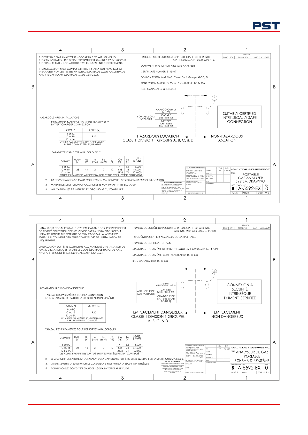
GPR-Portable Oxygen Analyzer User Manual
Appendix D - Hazardous Area Controlled Drawings
ProcessSensing.com 51
Page 58
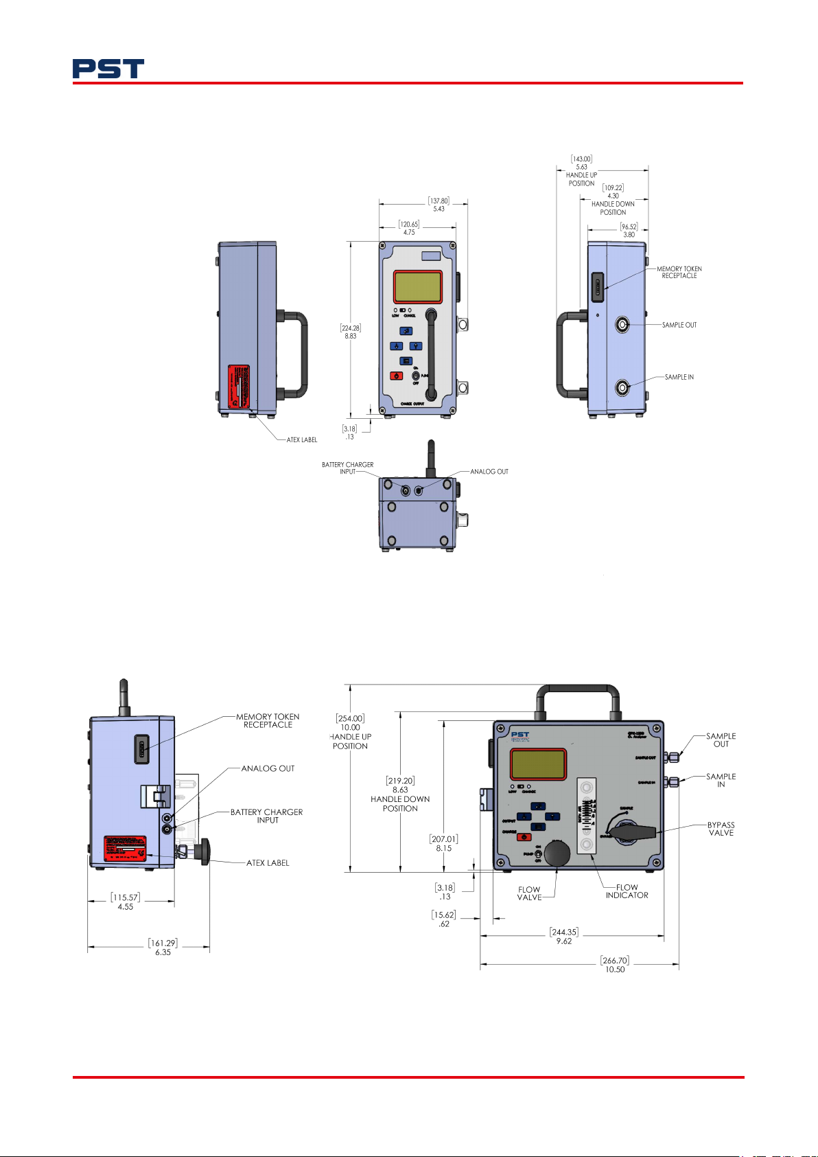
Appendix E - Dimensions
GPR-1100
GPR-Portable Oxygen Analyzer User Manual
GPR-1200
52 ProcessSensing.com
Page 59
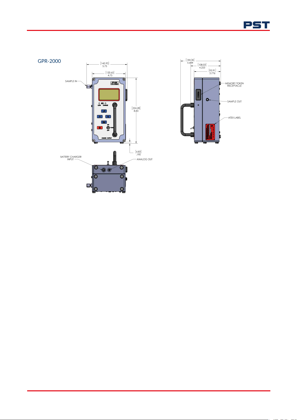
GPR-Portable Oxygen Analyzer User Manual
GPR-2000
ProcessSensing.com 53
Page 60
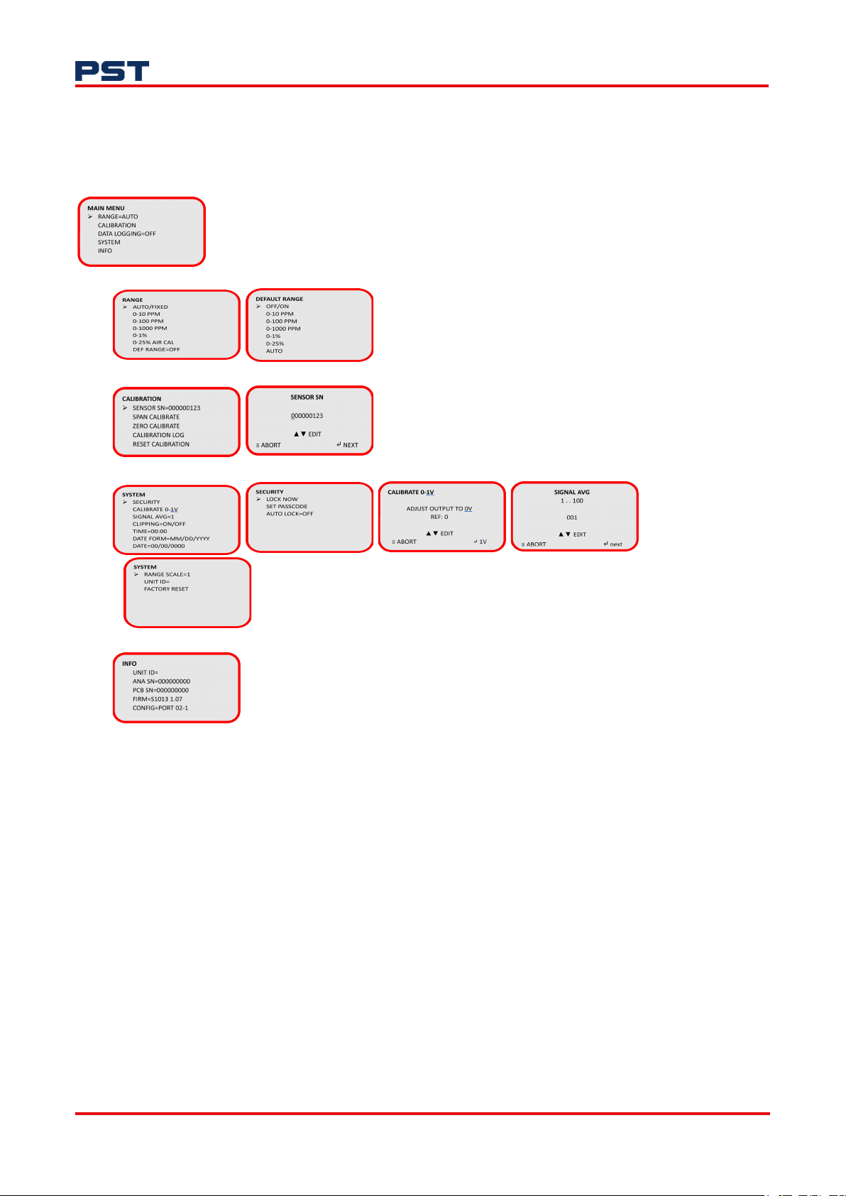
Appendix F - Menu Displays
GPR-Portable Oxygen Analyzer User Manual
NOTE: The menu structure may vary depending on your configuration.
54 ProcessSensing.com
Page 61

GPR-Portable Oxygen Analyzer User Manual
Appendix G - Spare Parts
GPR-1100 GPR-1200 GPR-2000
Sensors
GPR-12-333 ppm Oxygen sensor x x
GPR-12-333-H ppm Oxygen sensor for H2 and He gases x x
XLT-12-333 ppm Oxygen sensor for gases with < 0.5 % CO2 presence x x
GPR-11-60-4 % Oxygen sensor x
XLT-11-24-4 % Oxygen sensor for gases with < 0.5 % CO
Memory Token
LOGR-1003 Memory token x x x
LOGR-1005 Memory token to USB adapter
Operational Spares
PWRS-1003-KIT 9 V DC charger x x x
A-4771 Battery assembly (for portable without pump)
A-4770 Battery assembly (for portable with pump)
FITN-1003 Quick release plug - SS 1/8” NPT (qty 1) x
FLTR-1037 Coalescing filter element (for A-4442-1) x
CHEM-1008-2 H2 S scrubber media (1 liter) x x
Analyzer Hardware Spares
CONN-1034
A-2166
A-4665
Analog output mini plug
Sample pump
Sample pump switch
Carry case
Carry case
Carry case (portable with H2S scrubber)
Sensor cable
A-4383-2
B-2762-A-3-14
Sensor cable
Sensor top housing assembly
Sensor top housing assembly
ORNG-1007
Sensor housing O-ring (Viton)
Accessories
A-2734-6 Vent H2S scrubber assembly x
A-4442-1 Sample coalescing filter assembly x x
Panel with sample coalescing filter and vent H
Panel with sample flow meter x
Panel with sample coalescing filter and flow meter
Panel with sample coalescing filter, flow meter and vent H
scrubber
presence x
2
x x x
x x x
x x x
x x
x x
x x
x
x
x x
x x
x x x
S scrubber x
2
S
2
x
x
x
x
ProcessSensing.com 55
Page 62
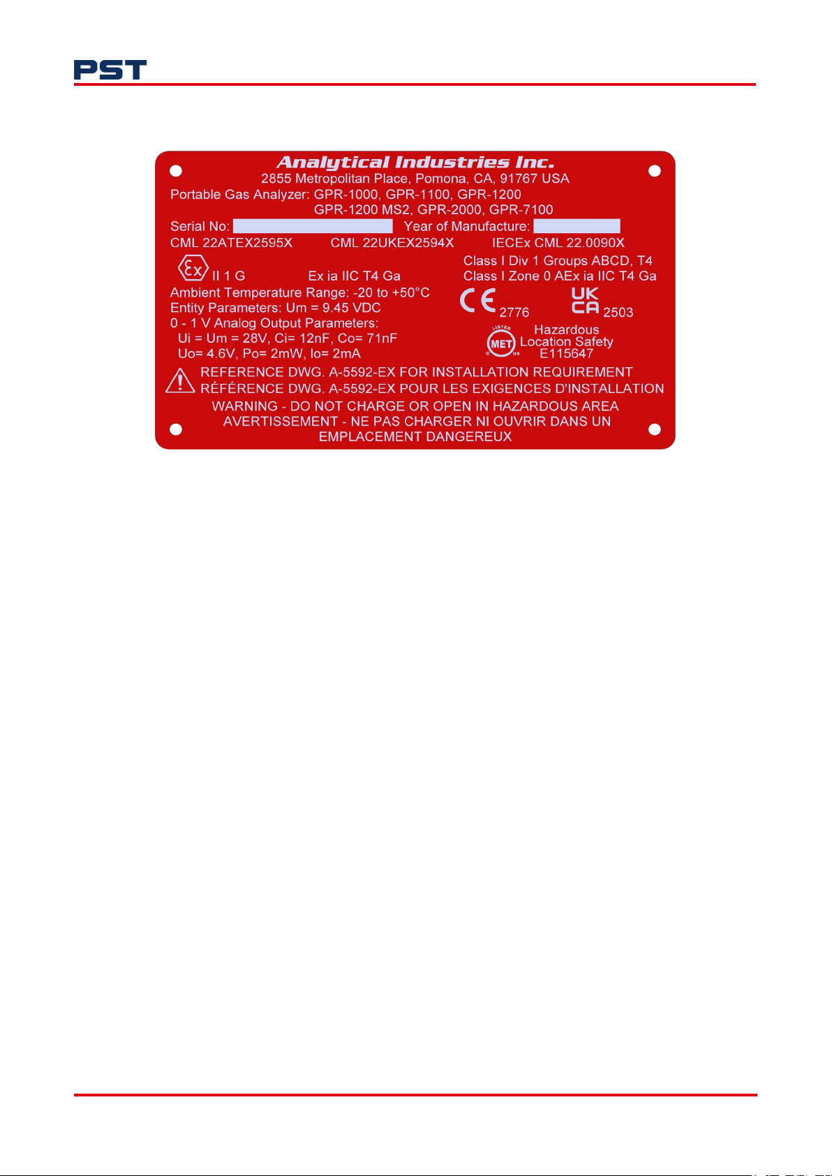
Appendix H - Hazardous Area Rating Plate
GPR-Portable Oxygen Analyzer User Manual
56 ProcessSensing.com
Page 63

GPR-Portable Oxygen Analyzer User Manual
Appendix I - Quality, Recycling, and Warranty Information
Analytical Industries Inc. (Aii) is part of the Process Sensing Technologies (PST) Group.
The PST Oxygen group of companies - Aii, Ntron and SST - comply with applicable
national and international standards and directives.
Full information can be found on this website
https://www.processsensing.com/en-us/resources/compliance/
The compliance site contains information on the following directives:
• ATEX (equipment for explosive atmosphere, Europe)
• CE
CMETUS (electrical equipment for hazardous areas, North America)
•
• IECEx
• REACH (Registration, Evaluation, Authorization, and Restriction of Chemicals)
• Recycling policy
• RoHS (Restriction of Hazardous Substances in electrical and electronic equipment
• UKCA
• WEEE (Waste Electrical and Electronic Equipment recycling.
ProcessSensing.com 57
Page 64

ProcessSensing.com
Analytical Industries Incorporated (Aii) is part of the Process Sensing Technologies Group plc (PST)
©2024 Process Sensing Technologies
 Loading...