

Page 1

.
FTB 371 Series
Axial Turbine Flow Meter
Page 2

Series FTB 371
- 2 -
Page 3

Series FTB 371
Copyright notice:
The reproduction, distribution and utilization of this operating manual as well as the communication of
its contents to others without express authorization is prohibited. Offe
payment of damages. All rights reserved in the event of the grant of a patent, utility model or design.
Table of contents page
0 About this operating manual ...................................................................................... 4
1 Device description ..................................................................................................... 5
1.1 Intended use............................................................................................................ 6
2 Safety instructions ..................................................................................................... 6
3 Important notes to installation and operation ............................................................. 7
4 Installation in piping ................................................................................................... 8
5 Electrical connection .................................................................................................. 9
5.1 FTB 371 with pulse output ....................................................................................... 9
6 Cleaning of the flow meter ....................................................................................... 10
7 Disassembly and disposal ....................................................................................... 11
8 Technical data ......................................................................................................... 12
8.1 FTB 371 with pulse output ..................................................................................... 12
8.2 Materials table ....................................................................................................... 13
8.3 Characteristic curv es , pr es sur e dr op ..................................................................... 13
8.4 Dimensions............................................................................................................ 14
nders will be held liable for the
Technical changes reserved - 3 -
Page 4

About this operating manual Series FTB 371
One Omega Drive, P.O. Box 4047
e-mail: [email protected]
WARNING! / CAUTION! Risk of injur y!
cause considerable damage to property.
CAUTION! Material damage!
NOTICE!
NO DOMESTIC WASTE!
Pay attention to and comply with
Check the specified points or notices.
0 About this operating manua l
• The operating manual is aimed at specialists and semi-skil l ed pers o nnel .
• Before each step, read through the relevant advice carefully and keep to the specified
order.
• Thoroughly read and understand the inform ation in the section "Safety instructions".
If you have any problems or questions, please contact your supplier or contact us directly
at:
Stamford, CT 06907-0047
Tel: (203) 359-1660
Hazard signs and other symbols used:
CAUTION! Electric current !
This sign indicates dangers which could arise from handling of electric current.
This sign indicates dangers that cause personal injuries that can lead to health defects or
This sign indicates actions which could lead to possible damage to material or environmental
damage.
ADHERE TO OPERATING MANUAL!
The device must not be disposed of
together with domestic waste.
information that is marked with this symbol.
Follow the specified instructions and steps.
Adhere to the given order.
This symbol indicates important notices,
tips o r i nformation.
Reference to another section, document or
source.
• Item.
- 4 -
Page 5

Series FTB 371 Device description
Flow meter components FTB 371:
1 Device description
The flow meter of the series FTB 371 from OMEGA ENGINEERI NG INC. is a transducer for
flow rate and total flow measurement.
It has an almost unlimited application through its exceptionally compact design, its very wide
measurement range and its convincing measurement accuracy.
Functional principle:
The liquid flowing into the flow meter is divided
by the guiding blades in four split beams. These
hit the rotor from four directions and put it in
motion. The uniform loadi ng of bearing from four
sides causes the forces to cancel themselves out
for the most part and wear is reduced to a
minimum.
The extremely hard bearing materials, sapphire
and hard metal, ensure in addition an
extraordinary life expectancy.
The rotor speed is transmitted to an electrical
pulse signal (frequency):
• The FTB 371 is equipped with magnets on
the rotor. A Hall-Effect sensor detects the
rotation of the rotor.
A flow-proportional frequency signal (square wave signal) is provided.
Technical changes reserved - 5 -
Page 6

Safety instructions Series FTB 371
1.1 Intended use
The flow meter of the series FTB 371 may only be used for flow rate measurements or
dosing of liquids. Never use them for gas measurements.
WARNING! No safety component!
The flow meter of the series FTB 371 is not a safety component in accordance with
Directive 2006-42-EC (Machine Directive).
Never use the FTB 371 as a safety component.
The operational safety of the device supplied is only guaranteed by intended use. The
specified limits ( § 8 "Technical data") may under no circumstances be exceeded.
Before ordering and installation, check that the material of the turbine flow monitor is suitable
to the medium to be measured and the application ( § 8.2 "Materials table").
2 Safety instructions
Before you install the FTB 371, read through this operating manual carefully. If the
instructions contained within it are not followed, in particular the safety guidelines, this
could result in danger for people, the environment, and the device and the system it is
connected to.
The FTB 371 corresponds to the state-of-the-art technology. This concerns the accuracy, the
operating mode and the safe operation of the device.
In order to guarantee that the device operates safely, the operator must act competently and
be conscious of safety is sues .
OMEGA ENGINEERING INC. provides support for the use of its products either personally or
via relevant literature. The customer verifies that our product is fit for purpose based on our
technical information. The customer performs customer- and application-specific tests to
ensure that the product is suitable for the intended use. With this verification all hazards and
risks are transferred to our customers; our warranty is not valid.
Qualified personnel:
The personnel who are charged for the installation, operation and maintenance of the
FTB 371 must hold a relevant qualification. This can be based on training or relevant
tuition.
The personnel must be aware of this operating manual and have access to it at all times.
The electrical connection should only be carried out by a fully qualified electrician.
General safety instructions:
In all work, the existing national regulations for accident prevention and safety in the
workplace must be complied with. Any internal regulations of the operator must also be
complied with, even if these are not mentioned in this manual.
You can mount the flow meter in any position. If it is installed into vertical pipes, the flow
direction is preferably upwards. You must avoid a free outlet.
- 6 -
Page 7

Series FTB 371 Important notes to installation and operation
The arrow which is placed on the flow meter() shows the only permitted flow direction.
For precise measurement, the length of the in- and outl e t tu bes must be observed
( § 3 "Important notes to installation and operation").
The internal diameter of the in- and outlet tube must correspond with the internal diameter
of the turbine flow monitor.
The flow medium to be monitored should preferably contain as few solid particles as
possible. Present particles must not exceed a diameter o f 0.5 mm. If necessary, install a
screen filter.
Avoid absolutely the formation of gas bubbles or cavitation in the medium by taking
proper measures.
The material of the series FTB 371 is not suitable for monitoring oils. The strength of the
used plastic parts would be considerably reduced.
In order to clean the flow monitor of contaminations, flush the unit reverse to the flow
direction ( § 6 "Cleaning of the flow meter").
Suitable measures sho ul d be tak en to pr event the medium from freezing.
A possible blowing out of the device FTB 371 must take place only in opposite direction to
the flow.
We recommend to use only screened connection cables. Connect the shield on one side
(the wire ends) on ground.
Attention:
The union nut of the sensor (Hall-Effect-Sensor or inductive proximity switch) is sealed
and must not be opened!
When you still open this component, the fixation of the turbine system is disturbed and it
will be damaged.
Special safety instructions:
Warnings that are specifically relevant to individual operating procedures or activities can be
found at the beginning of the relevant sections of this operating manual.
3 Important notes to installation and operation
Observe the following instructions in order to achieve highest-possible measurement
accuracy and specified output signal:
• Before installing the turbine flow monitor flush the pipe carefully. You avoid a blocking of
the turbine caused by partic l es fro m the pi pe i nstal l ati on .
• The installation position of the flow monitor is unreserved. If it is installed into vertical
pipes, the flow direction is preferably from below upward. You must avoid a free outlet.
• The arrow which is placed on the flow monitor () shows the only permitted flow
direction.
Technical changes reserved - 7 -
Page 8
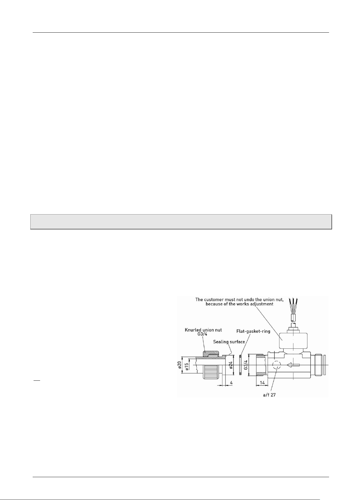
Installation in piping Series FTB 371
• In order to achieve the best measurement accuracy, a straight tube in front of the flow
monitor must be retained, min 10 x DN. Behind the flow monitor, a straight outlet tube of
5 x DN must be kept.
The internal diameter of the in- and outlet tubes must correspond with the internal
diameter of the flow monitor. Before and behind the stabilization tubes, the line may be
contracted or enlarged .
In practice these instructions often can not be observed. Then the pulse rate and the
measurement accuracy can be affected.
• The flow medium to be monitored should preferably contain as few solid particles as possible.
Present particles must not exceed a diameter of 0.5 mm. If necessary, install a screen
filter!
• The material of the series FTB 371 is not suitable for monitoring oils. The strength of the
used plastic parts would be considerably reduced.
• Attention:
The union nut of the sensor (Hall-Effect-Sensor or inductive proximity switch) is sealed
and must not be opened!
When you still open this component, the fixation of the turbine system is disturbed and it
will be damaged.
4 Installation in piping
Now you can install the flow meter in the piping system which w as prepared ac cor di ng to § 3.
Note:
• Use only a suitable compound for sealing.
If you seal the male thread, take care that no fibrous sealing compounds get into the
turbine (hemp or Teflon strip).
Installation:
Make sure that your piping system has
a collar. The face of the collar serves as
sealing area. The collar is pressed
against the flat seal by the prov i ded
knurled union nut.
Now install the turbine. Make sure that
the provided seals fit properly and
tighten the union nuts.
You must tighten the plastic union nuts
with a torque of max. 8 Nm.
- 8 -
Page 9

Series FTB 371 Electrical connection
5 Electrical connection
Attention: We recommend to use only screened cables. Connect the shield on one side (the
wire ends) on ground.
5.1 FTB 371 with pulse output
The output signal of the flow meter is a flow-proportional frequency signal. The shape of the
signal is a square wave and its amplitude corresponds approximately with the supply voltage.
It is an open collector signal, NPN- or PNP-switching.
The connected electronic instrument should have a loading resistance (pull-up or pull-down
resistor) of 5 kΩ in the inlet.
Schematic representation:
A connection is made with three leads, the supply voltage must be connected between +U
and GND (ground), the output signal can be tapped between and GND. The colour
assignment of the supply cables can be taken from the sketch on the type plate.
FTB 371 with connecting cable:
Colour code:
BN = brown
GN = green
WH = white
R = resistor
Technical changes reserved - 9 -
Page 10

Cleaning of the flow meter Series FTB 371
6 Cleaning of the flow meter
Attention:
The union nut of the sensor is sealed and must not be
opened!
When you still open this component, the fixation of the
turbine system is disturbed and it will be damaged.
A repair in the factory becomes necessar y!
To remove dirt from the flow meter, you should flush it
with water reverse to the flow direction.
• Warning:
The FTB 371 may only be blown ag ai nst th e fl ow
direction with compressed air.
When blowing out in flow direction, the turbine bearing can be damaged.
- 10 -
Page 11

Series FTB 371 Disassembly and disposal
7 Disassembly and disposal
CAUTION! Risk of injury!
Never remove the device from a plant in operation.
Make sure that the plant is shut down professionally.
Before disassembly:
Prior to disassembly, ensure that
the equipment is switched off and is in a safe and de-energised state.
the equipment is depressurised and has cooled down.
Disassembly:
Remove the electrical connectors.
Remove the FTB 371 using suitable tools.
Disposal:
NO HOUSEHOLD WASTE!
The FTB 371 consists of various different materials. It must not be disposed of with
household waste.
Take the FTB 371 to your local recycling plant
or
send the FTB 371 back to your supplier or to
OMEGA ENGINEERING INC..
Technical changes reserved - 11 -
Page 12

Technical data Series FTB 371
Characteristics measurement device
Measuring range
2...40 l/min • with continuous operation max. 20 l/min
Accuracy
±1 % of range
Repeatability
±0.2 %
Signal output from
< 0.3 l/min
Sensor
Hall-sensor
Characteristics output signal
Pulse rate / K-factor
855 pulses/l
Resolution
1.2 ml/pulse
Signal shape
Square wave signal
NPN open collector
Signal current, max.
10 mA
Pull-up-resistor
5 kΩ (recommendation)
Electrical characteristics
Supply voltage
4.5...24 VDC
Current consumption
< 10 mA
Electrical connection:
max
70 °C
Degree of protection (EN 60529)
IP 54
Process variables
Medium temperature, max.
85 °C
Medium temperature, min.
0 °C, not freezing
Ambient temperature
0…75 °C
Nominal diameter
DN 15
Nominal pressure
PN 10
Particle size in the medium
< 0.5 mm
Process connection
¾" BSP male
with union nuts and flat seals
8 Technical data
The technical data of customised versions may differ from the data in these instructions.
Please observe the information specified on the type plate.
8.1 FTB 371 with pulse output
Type FTB 371
*1)
- Cable, screened
=
T
*1) The stated values refer to operation with water at 20 °C. Monitoring of fluids with higher viscosities is possible with the
effect of deviations from mentioned values.
1.5 m PVC
- 12 -
Page 13

Series FTB 371 Technical data
Pipe section
Brass
CW602N
Turbine sytem
PEI ULTEM
X
Rotor assembly
Hard ferrite magnets
X
Bearing system / shaft
Shaft Arcap AP1D with hard metal pins in sapphire bearings
X
Bearings support
Shaft Arcap AP1D
X
Union nut sensor
PA 6
-/-
Sensor
PPO Noryl GFN3
X
Knurled unnion nuts
PA 66
O-ring / flat gasket
NBR
X
Screen filter (optional)
POM / Stainless steel
X
Characteristic curves:
Pressure drop:
8.2 Materials table
Type FTB 371 *1)
X
*1) Wetted components.
8.3 Characteristic curves, pressure drop
Technical changes reserved - 13 -
Page 14
Technical data Series FTB 371
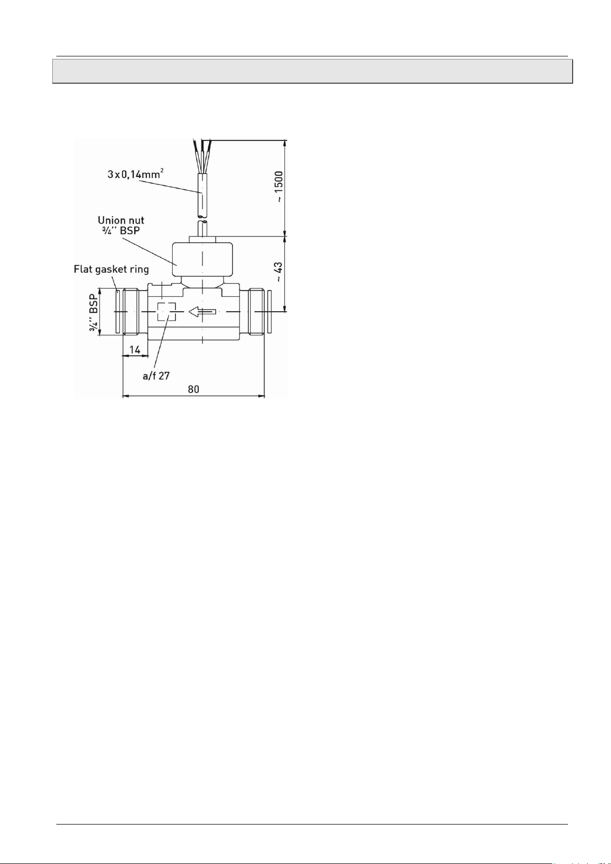
8.4 Dimensions
FTB 371
- 14 -
Page 15

Series FTB 371
Technical changes reserved - 15 -
Page 16

Series FTB 371
M-5660/0517
- 16 -
 Loading...