

Page 1
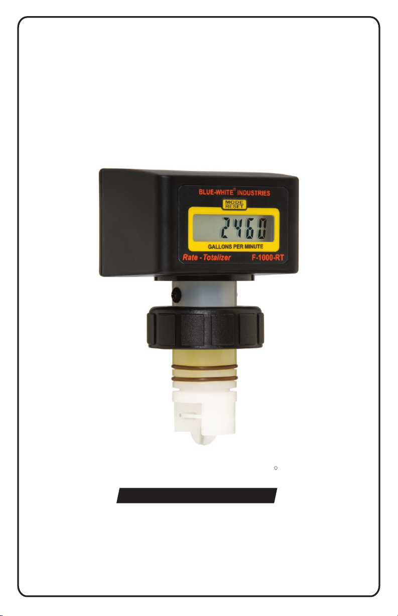
F-1000
INSTRUCTION MANUAL
R
Blue-White
Industries, Ltd.
5300 Business Drive
Huntington Beach, CA 92649
USA
Phone: 714-893-8529 FAX: 714-894-9492
E mail: [email protected] or [email protected]
Website: www.blue-white.com
Page 2

Page 2
F-1000
TABLE OF CONTENTS
SECTION HEADING PAGE
1..................................Introduction...................................................2
2..................................Specifications................................................3
3..................................Features........................................................4
4..................................How to install the meter.................................5
4.1.........................Mounting location..........................................5
4.2.........................Pipe Flow Stream Requirements...................6
4.3.........................How to install Your Saddle Fitting..................8
4.3.1................Drill the Mounting Hole..................................9
4.3.2................Install the Saddle...........................................9
4.3.3................Check the Saddle Alignment.........................9
4.3.4................Install the Sensor..........................................10
4.4.........................Installing the Molded In-Line Fitting (MI).......10
4.5.........................How to Install Molded PVC Tee Fitting..........11
5..................................How to Operate the meter.............................12
6..................................Flow Ranges.................................................9 - 10
7..................................Maintenance..................................................15
8..................................Troubleshooting.............................................14
9..................................Replacement Parts List.................................16
1.0 INTRODUCTION TO THE F-1000
Congratulations on purchasing the F-1000 electronic flow meter. The F-1000 is
designed to measure the flow of a fluid in a pipe. The meter is factory calibrated to
any engineering units and displays the rate of flow or the total of flow on a 6 digit LCD
display. Two AAA batteries power the unit for up to one year. There are three models
are available:
F-1000-RB is a rate meter - designed to measure and display the rate of flow.
F-1000-TB is a totalizer meter - designed to measure and display the total flow.
F-1000-RT is a rate/totalizer meter - designed to measure and display both the rate
of flow and the total flow.
Page 3
F-1000
Page 3
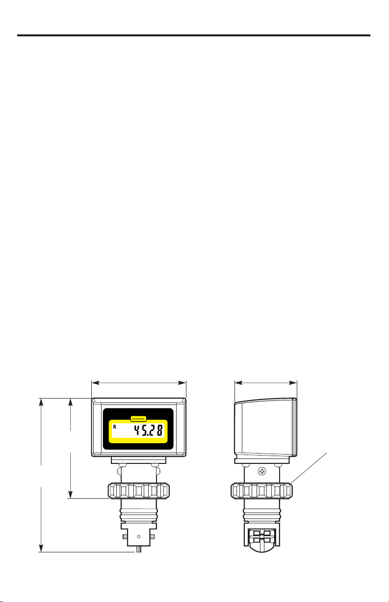
2.0 SPECIFICATIONS
Maximum Working Pressure*...................300 psig / 20.7 bar
Maximum Fluid Temperature*..................200 F / 93.3 C - Saddle and sensor
200 F / 93.3 C - When mounted on
140 F / 60 C - When mounted on
Ambient Temperature Range...................32 to 110 F / 0 to 43 C
Enclosure .NEMA 4X (acceptable for outdoor use)............................................
NOTE: Protect the LCD display from
Accuracy +/-2% of full scale rate reading..............................................
Repeatability +/-1% of full scale rate reading........................................
Power Requirements Two standard AAA alkaline batteries .............................
Battery Life Expectancy 1 year minimum.........................
o o
only
o o
polypropylene and PVDF inline units.
o o
molded PVC tee units or PVC pipe.
o o o o
direct sunlight.
(included)
3.10 in.
(78.7 mm)
4.93 in.
(125.2 mm)
3.03 in.
(77 mm)
®
BLUE-WHITE INDUSTRIES
MODE
RESET
GALLONS PER MINUTE
F-1000-RTRate - Totalizer
2.00 in.
(50.8 mm)
Union Nut
Fig. 1
Page 4
Page 4
Type Of Disturbance
Minimum Inlet
Pipe Length
Minimum Outlet
Pipe Length
Flange
10 X Pipe I.D.
5 X Pipe I.D.
Reducer
15 X Pipe I.D.
5 X Pipe I.D.
90 Elbow
20 X Pipe I.D.
5 X Pipe I.D.
Two 90 Elbow - 1 Direction
25 X Pipe I.D.
5 X Pipe I.D.
Two 90 Elbows - 2 Directions
40 X Pipe I.D.
5 X Pipe I.D.
Pump or Gate ValvesValves
50 X Pipe I.D.
5 X Pipe I.D.
F-1000
3. FEATURES
!
Easy to read .35" high, six digit
LCD display
!
Installs quickly on existing pipe
!
Factory calibrated - nothing to
program
!
Minimal maintenance required
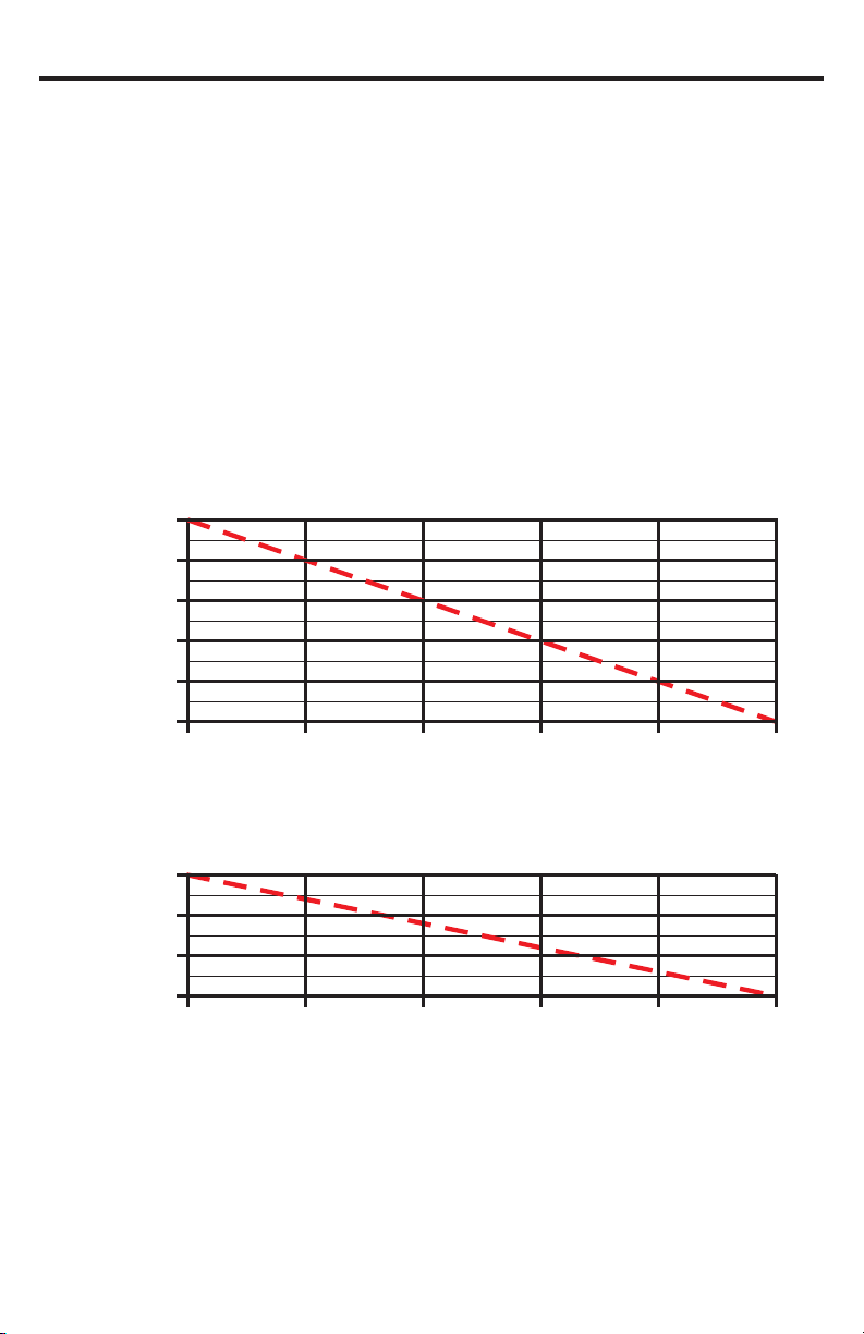
*Temperature vs. Pressure
Temperature
200°F (93.3°C)
175°F (79.4°C)
150°F (65.5°C)
125°F (51.6°C)
100°F (37.8°C)
70°F (21.1°C)
When mounted on Polypropylene and PVDF inline units or PVDF Saddles
0 (0) 60 (4.1) 120 (8.3) 180 (12.4) 240 (16.5) 300 (20.7)
!
No pressure drop
!
Weather resistant enclosure
!
Corrosion resistant PVDF sensor,
ABS enclosure
!
High accuracy
!
Large calibrated flow range
PSIg (BAR)
Temperature
140°F (60°C)
120°F (48.9°C)
100°F (37.8°C)
70°F (21.1°C)
0 (0)
When mounted on Molded PVC Tee or PVC pipe units
*Pressure and temperature limits are inversely proportional.
60 (4.1)
120 (8.3)
PSIg (BAR)
180 (12.4) 240 (16.5)
Fig. 2
300 (20.7)
Page 5
F-1000
Type Of Disturbance
Minimum Inlet
Pipe Length
Minimum Outlet
Pipe Length
Flange
10 X Pipe I.D.
5 X Pipe I.D.
Reducer
15 X Pipe I.D.
5 X Pipe I.D.
90 Elbow
20 X Pipe I.D.
5 X Pipe I.D.
Two 90 Elbow - 1 Direction
25 X Pipe I.D.
5 X Pipe I.D.
Two 90 Elbows - 2 Directions
40 X Pipe I.D.
5 X Pipe I.D.
Pump or Gate ValvesValves
50 X Pipe I.D.
5 X Pipe I.D.
Page 5
4.0 HOW TO INSTALL THE F-1000
4.1 MOUNTING LOCATION
Note: All diagrams are strictly for guideline purposes only. Always consult an
expert before installing the F-1000 on specialized systems.
Note: The F-1000 should be serviced by qualified persons only.
Although the F-1000 is designed to withstand outdoor conditions, a cool, dry
location where the unit can be easily serviced is recommended. The life of the LCD
display will be severely reduced when installed in direct sunlight. Do not install the
meter so that the LCD is in direct sunlight.
!
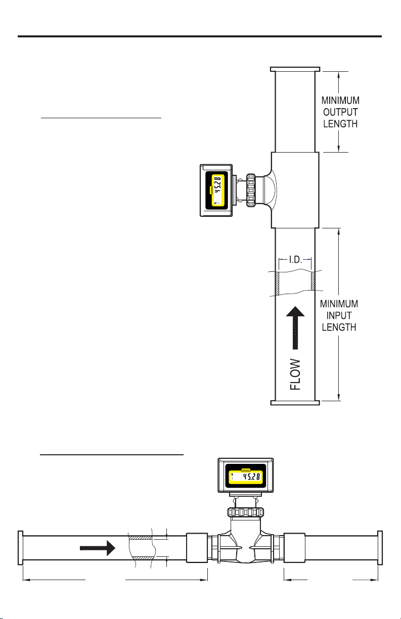
The F-1000 can be mounted on horizontal or vertical runs of pipe (see figure 4, 5
and 6). Mounting anywhere around the diameter of vertical pipe is acceptable,
however, the pipe must be completely full of water at all times. Back pressure is
essential on downward flows.
!
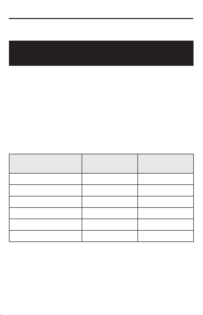
The F-1000 accuracy is affected by disturbances such as pumps, elbows, tees,
valves in the flow stream. Install the meter in a straight run of pipe as far as
possible from any disturbances. The distance required for accuracy will depend
on the type of disturbance.
!
The pipe must be completely full at all times. Air bubbles or air pockets in
the flow stream will adversely affect the reading. A small amount of back
pressure is recommended in horizontal runs of pipe.
!
The F-1000 is powered by two AAA batteries. Life expectancy is one
year minimum.
Page 6
Page 6
F-1000
4.2 PIPE FLOW STREAM REQUIREMENTS
!
The F-1000 accuracy is based on steady, undisturbed flow with a fully developed turbulent flow profile. Pulsating, swirling and other disruptions in the flow
stream will effect the meter’s accuracy.
!
The F-1000 is factory calibrated to ± 2% of full scale rate reading. When measuring total flow, accumulated error over time must be considered. Accuracy is
based on laboratory testing of nominal pipe dimensions. Your actual accuracy
will vary based on your actual pipe I.D. And other installation factors.
!
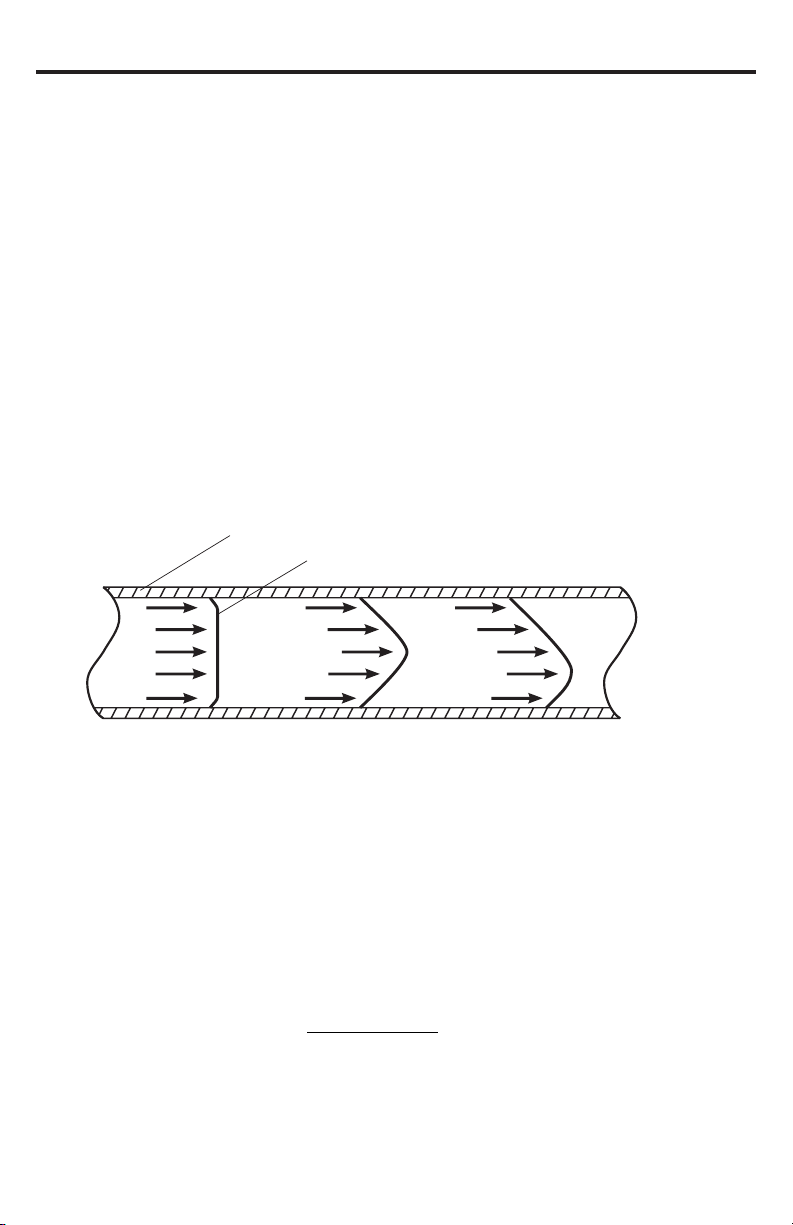
There are two basic types of flow profiles; turbulent and laminar (see figure 3).
Turbulent flow exists when the speed of the fluid flowing in the pipe is nearly
constant across the entire width of the pipe. This is typical of low viscosity fluids;
like water, flowing at high velocity. Laminar flow exists when the speed of the
fluid flowing in the center of the pipe is greater than the speed of the fluid at the
outer edge near the pipe wall. This is typical of high viscosity fluids flowing at low
velocity. Because the F-1000 is measuring the fluid near the pipe wall only
(especially in larger pipe sizes), a constant flow velocity across the flow stream
is required.
Pipe Cross Section
Flow Velocity Profile
Fig. 3
Fully Developed
Turbulent Flow
To determine which type of flow exists in your installation, the following is required:
Flow rate of the fluid in GPM - Q
Specific gravity of the fluid - G
Pipe inside diameter in inches - D
Fluid viscocity in centepoise - V
Use the following equation to determine the REYNOLDS NUMBER:
REYNOLDS NUMBER = 3160 x Q x G
D x V
Flow conditions with a Reynolds Number greater than 4000 is fully developed
turbulent flow. A Reynolds Number less than 2000 is laminar flow. The F-1000
requires a Reynolds number greater than 4000 to maintain accuracy.
Laminar
Disturbed Flow
(due to swirling)
Page 7
F-1000
Vertical Mount
®
BLUE-WHITE INDUSTRIES
MODE
RESET
Page 7
Fig. 4
F-1000-RTRate - Totalizer
GALLONS PER MINUTE
Horizontal Mount
Fig. 5
FLOW
MINIMUM
INPUT
LENGTH
I.D.
®
BLUE-WHITE INDUSTRIES
MODE
RESET
GALLONS PER MINUTE
F-1000-RTRate - Totalizer
MINIMUM
OUTPUT
LENGTH
Page 8
Page 8
F-1000
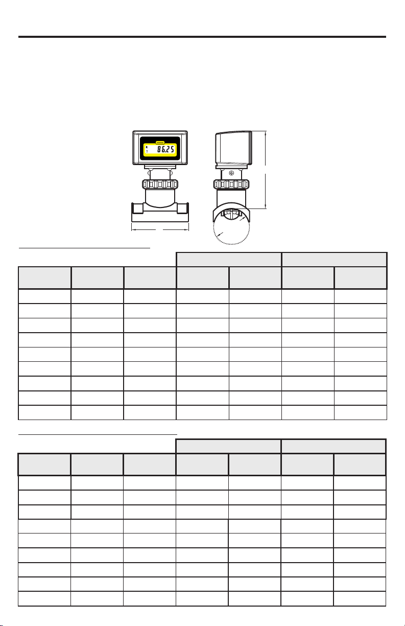
4.3 HOW TO INSTALL YOUR F-1000 SADDLE FITTING
The F-1000 saddle is designed to mount on smooth schedule 40 IPS pipe, schedule
80 IPS pipe (ASTM-D-1785) , PN10 metric pipe or PN16 metric pipe (DIN 8062).
The outside of the pipe must be clean, smooth and free of surface imperfections.
The outside diameter must be as specified to ensure a leak free installation. The
inside diameter must be as specified to ensure meter accuracy.
®
BLUE-WHITE INDUSTRIES
MODE
RESET
GALLONS PER MINUTE
F-1000-RTRate - Totalizer
H
PIPE O.D.
L
(Outside Diameter)
I.P.S. Pipe Sizes (in inches)
(ASTM-D-1785)
Nominal
Pipe Size
1-1/2”
2”
2.5”
3”
4”
6”
8”
Length
3-3/16”
3-3/16”
3-3/16”
3-3/16”
3-3/16”
3-3/16”
3-3/16”
10”
12”
4-1/2”
4-1/2”
Height
4-5/16”
4-5/16”
4-5/16”
4-5/16”
4-5/16”
4-1/4”
4-1/4”
4-1/4”
4-1/4”
Schedule 40 Schedule 80
Outside
Diameter
1.900
2.375
2.500
3.500
4.500
6.625
8.625
10.750
12.750
Inside
Diameter
1.610
2.067
2.469
3.068
4.026
6.065
7.981
10.020
11.938
Metric Pipe Sizes (in millimeters)
(DIN 8062)
Nominal
Pipe Size
50 mm
63 mm
75 mm
90 mm
110 mm
160 mm
200 mm 81 200.0 180.8 200.0 170.2
Length
81
81
81
81
81
81
Height
110
110
110
110
110
108
108
Outside
Diameter
Pn10 Pn16
Inside
Diameter
50.0
63.0
75.0
90.0
110.0
160.0
45.2
57.0
67.8
81.4
99.4
144.6
250 mm 114 108 250.0 226.2 N/A N/A
315 mm 114 315.0 285.0 N/A N/A
108
Fig. 7
Outside
Diameter
1.900
2.375
2.500
3.500
4.500
6.625
8.625
10.750
12.750
Outstide
Diameter
50.0
63.0
75.0
90.0
110.0
160.0
Inside
Diameter
1.500
1.939
2.323
2.900
3.826
5.761
7.625
9.564
11.376
Inside
Diameter
42.6
53.6
63.8
76.6
93.6
136.2
Page 9
F-1000
4.3.1 DRILL THE MOUNTING HOLE
!
Select an area on the pipe as outlined in section 4.1. Be sure the surface area of
the pipe is clean and smooth.
!
Drill a 1-1/8" diameter hole through the pipe wall. The F-1000 meter can be
installed up to 45 degrees from the top of the pipe. A hole saw kit is available
from the factory, order part number 20000-062.
!
Clean all burrs from inside and outside the hole. Use fine sandpaper (440 grit) if
necessary.
4.3.2 INSTALL THE SADDLE
!
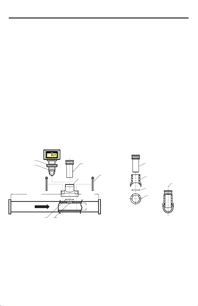
Insert the alignment tool through the top of the saddle. Proper alignment is
critical! Slide the large O-ring over the bottom of the alignment tool and into the
groove on the underside of the saddle.
!
With the alignment tool and O-ring in place, position the saddle over the drilled
hole. Insert the alignment tool into the hole seating the saddle. Be sure the Oring is properly seated in the O-ring groove. Place the pipe clamps around the
pipe and into the slots on the saddle. Tighten the clamps in an alternating
method.
®
BLUE-WHITE INDUSTRIES
MODE
RESET
GALLONS PER MINUTE
Union Nut
Sensor Body
O-rings
See Chart
on Page 4
F-1000-RTRate - Totalizer
Alignment
Tool
Saddle
See Chart
on Page 4
Fig. 8
Hose Clamps
Alignment
Tool
Saddle
O-ring
Pipe
Page 9
Center Line
FLOW
Drill Hole 1.125±Saddle O-ring
I.D.
.030
In. Diameter On Center
.000
4.3.3 CHECK THE SADDLE ALIGNMENT
!
Pull the alignment tool out of the saddle. (If the tool is not easily removed, slightly
loosen the clamps) Inspect the hole. The saddle must be mounted directly over
the hole. Adjust the saddle alignment until the alignment tool slides freely in and
out of the saddle.
!
Be certain the O-ring is properly seated and visible in the groove around the hole.
!
Tighten the clamps.
Page 10
Page 10
F-1000
4.3.4 INSTALL THE F-1000 SENSOR
!
Be sure two O-rings are located on the sensor body. The O-rings have been
lubricated at the factory with silicone oil.
!
Push the sensor assembly into the saddle with a twisting motion. The notch on
the sensor body must fit into the slot on the saddle. Be sure the sensor is fully
inserted into the saddle.
!
HAND TIGHTEN the union nut.
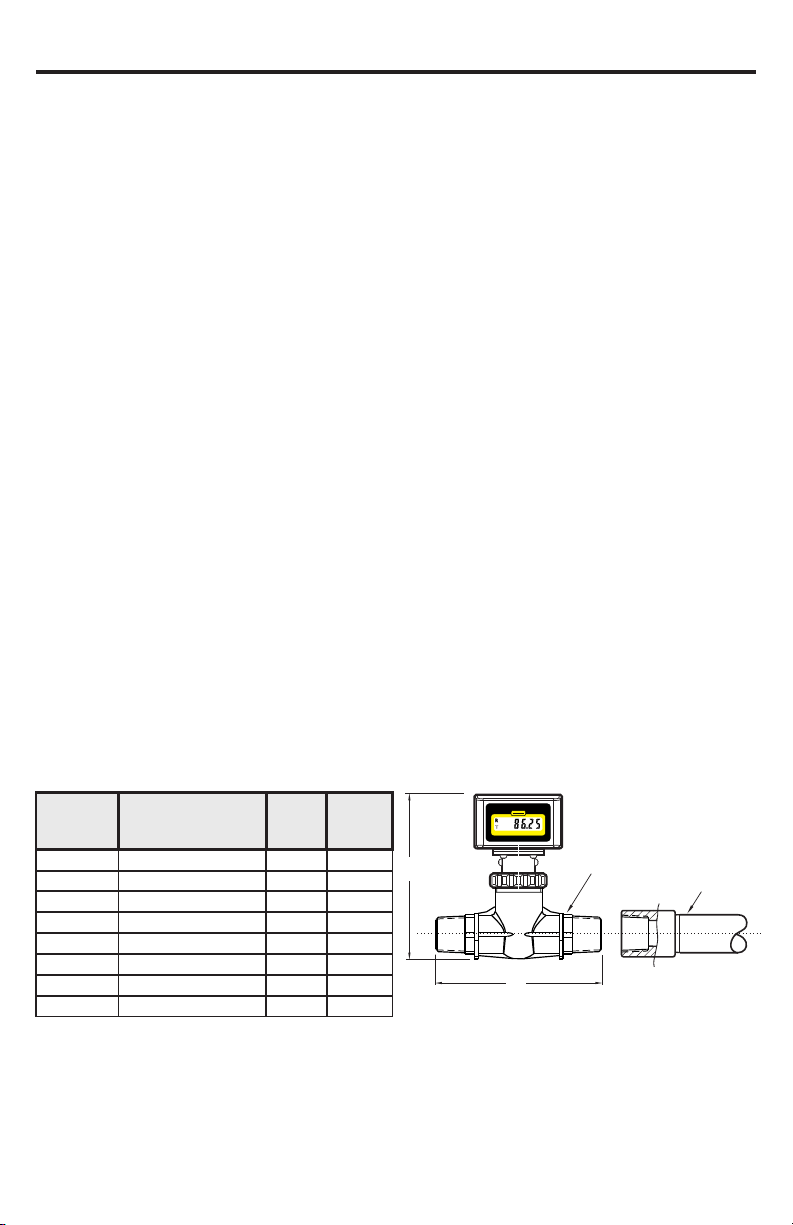
4.4 INSTALLING THE MOLDED IN-LINE FITTING (MI)
All molded in-line (MI) fittings have male American National Standard Taper Pipe
Threads (MPT).
!
Select an area on the pipe as outlined in section 4.1.
!
Install the F-1000 as you would any other plastic pipe fitting. Be sure the inlet and
outlet fittings are aligned properly. Improper alignment of the fittings will put
stress on the adapter connections and may cause leaking or fitting damage. Do
not over tighten the fittings. Use PTFE tape sealant only on the adapter threads.
!
The F-1000 can be mounted on horizontal or vertical runs of pipe. Mounting at
the twelve o'clock position on horizontal pipe is recommended. Mounting
anywhere around the diameter of vertical pipe is acceptable, however, the pipe
must be completely full of water at all times. See figure 4, 5 and 6.
!
Be sure the inlet and outlet plumbing is properly secured. The F-1000 is not
designed to support the weight of related piping. Improperly supported pipes will
put stress on the adapter connections and may cause leaking or fitting damage.
Nominal
Pipe Size
3/8”
3/8”
1/2”
1/2”
3/4”
3/4”
1.0”
1.0”
Body Description
3/8” MPT-low flow
3/8” MPT-std flow
1/2” MPT-low flow
1/2” MPT-std flow
3/4” MPT-low flow
3/4” MPT-std flow
1.0” MPT-low flow
1.0” MPT-std flow
Length
L
4.73”
4.73”
5.09”
5.09”
5.25”
5.25”
5.65”
5.65”
Height
H
5.29”
5.38”
5.29”
5.38”
5.38”
5.57”
5.57”
5.57”
®
BLUE-WHITE INDUSTRIES
MODE
RESET
GALLONS PER MINUTE
F-1000-RTRate - Totalizer
Molded in-line body
H
L
with M P T
Pipe
Fig. 10
Page 11
F-1000
Page 11
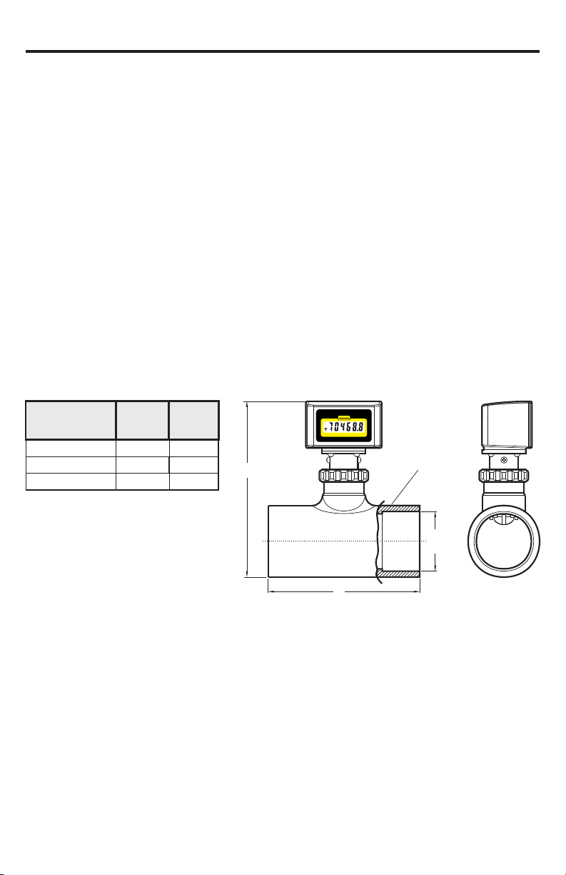
4.5 HOW TO INSTALL MOLDED PVC TEE FITTINGS (TE)
!
Select an area on the pipe as outlined in section 4.1.
!
Remove the F-1000 sensor from the tee fitting. Do not glue the TEE while the
sensor is installed.
!
Install the F-1000 tee fitting as you would any other plastic pipe solvent weld
(glue) fitting. Do not use too much glue. Excessive glue may create a disturbance in the flow stream which will effect the accuracy of the meter.
!
The F-1000 can be mounted on horizontal or vertical runs of pipe. Mounting at
the twelve o'clock position on horizontal pipe is recommended. Mounting
anywhere around the diameter of vertical pipe is acceptable, however, the pipe
must be completely full of water at all times. See figure 4, 5 and 6.
!
Install the F-1000 sensor. Be sure two O-rings are located on the sensor body.
The O-rings have been lubricated at the factory with silicone oil. Push the
sensor assembly into the saddle with a twisting motion. The notch on the sensor
body must fit into the slot on the saddle. Be sure the sensor is fully inserted into
the saddle. HAND TIGHTEN the union nut.
®
Nominal Pipe
Size
1”
1-1/2”
2”
LengthLHeight
H
4”
4-1/2”
4-3/4”
6”
6-5/8”
7-1/8”
H
BLUE-WHITE INDUSTRIES
MODE
RESET
GALLONS PER MINUTE
F-1000-RTRate - Totalizer
Tee Fitting
Nominal
Pipe Size
L
Fig. 11
Page 12
Page 12
F-1000
5.0 HOW TO OPERATE THE F-1000
Note: The calibrated units of measure such as GPM, LPM, M3H, GALLONS,
LITERS, CUBIC METERS, etc., And the decimal point location are preprogrammed
at the factory to standard flow ranges (see chart). Any unit of measure can be
factory programmed. Please contact the factory for details.
!
The meter is shipped from the factory with 2 AAA batteries installed.
!
When measuring continuous flow (i.e. 24 hours per day, 7 days per week), do
not operate the meter in the upper 25% of the calibrated flow range. The paddle
speed in these high flow ranges is fast. Damage to the paddle may occur if the
meter is allowed to run continuously at the high flow rate, especially with
corrosive or abrasive fluids.
!
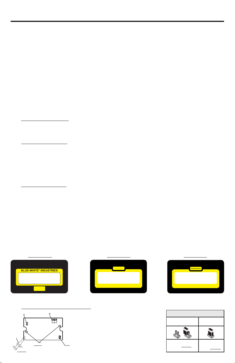
Model F-1000-RB:The F-1000-RB is the basic rate meter. The meter will
display the rate of flow from .01 through 999999 in any engineering units. Some
standard units of measure are GPM, GPH, GPD, LPM, LPH, LPD, M3H, etc.
!
Model F-1000-TB:The F-1000-TB is the basic totalizer meter. The meter will
display the total flow amounts from .01 through 999999 in any engineering units.
Some standard units of measure are GALLONS, LITERS, CUBIC METERS.
Pressing and holding the RESET button (located on the front panel) for at least
2.0 seconds resets the total to zero. This feature can be disabled -- see Fig. 12
below.
!
Model F-1000-RT:The F-1000-RT is the rate and totalizer meter. The meter will
display the flow rate amounts and the total flow amounts from .01 through
999999 in any engineering units. Some standard units of measure are
GALLONS PER MINUTE, GALLONS PER HOUR, GALLONS PER DAY,
LITERS PER MINUTE, LITERS PER HOUR, LITERS PER DAY, CUBIC
METERS PER HOUR, CUBIC METERS PER DAY. Pressing the RESET button
(located on the front panel) toggles the display between flow rate and total flow.
Pressing and holding the RESET button for at least 2.0 seconds while the total
flow value is displayed will reset the total to zero. This feature can be disabled .
See Fig. 12 below.
F-1000-RB
F-1000-RBFlow Rate Meter
®
BLUE-WHITE INDUSTRIES
GPM
F-1000 Circuit Board
Mounting holes (x2)
Terminal blocks
(AC Coil sensor input)
21
Fig. 12
(Front Panel Totalizer Reset
Black wire
(Negative lead)
Red wire
(Positive lead)
Battery size: two AAA (1.5 V each)
Header pins
(Tail membrane connector)
+
Screw size: #4 x .50 Philip oval “A”
Jumpers
Enable/Disable)
F-1000-TB F-1000-RT
RESET
GALLONS
®
F-1000-TBFlow Totalizer
BLUE-WHITE INDUSTRIES
GALLONS PER MINUTE
JUMPER CONFIGURATION
Jumper Not
Installed (open)
Total flow reset
to zero Enable
(Factory default)
BLUE-WHITE INDUSTRIES
MODE
RESET
®
F-1000-RTRate - Totalizer
Jumper
Installed
Total flow reset
to zero Disable
Page 13
F-1000
Page 13
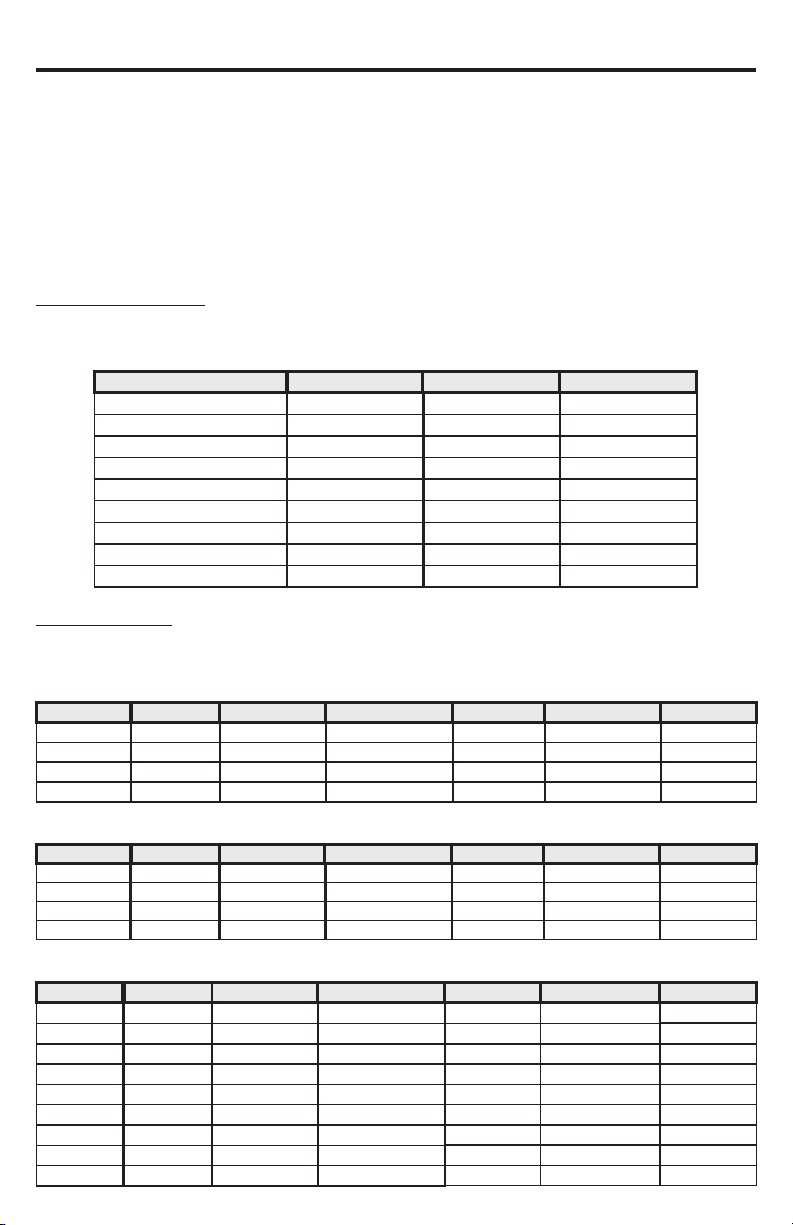
! 6.0 FLOW RANGES
! The F-1000 is factory calibrated to ± 2% of full scale rate reading. When
measuring total flow, accumulated error over time must be considered.
Accuracy is based on laboratory testing of nominal pipe dimensions. Your actual
accuracy will vary based on your actual pipe I.D. And other installation factors.
! Due to increased wear on the paddle and axle, continuous operation at the
upper 25% of the flow range is not recommended.
METRIC PIPES
(Meet DIN 8062)
SADDLES - Standard Flow [Min - Max]
Pipe Size
50 MM - PN 10 & PN 16
63 MM - PN 10 & PN 16
75 MM - PN 10 & PN 16
90 MM - PN 10 & PN 16
110 MM - PN 10 & PN 16
160 MM - PN 10 & PN 16
200 MM - PN 10 & PN 16
160 MM - PN 10
200 MM - PN 10
LPM 1
110 - 1100
150-1500
230 - 2300
350 - 3500
720 - 7200
1150 - 11500
1700 - 17000
2700 - 27000
LPH 1
4200 - 4200070.0 - 700.0
6600 - 66000
9000 - 90000
13800 - 138000
21000 - 210000
43000 - 430000
70000 - 700000
100000 - 1000000
170000 - 1700000
M3H 1
4.20 - 42.00
6.60 - 66.00
9.00 - 90.00
13.8 - 138.0
21.0 - 210.0
43.0 - 430.0
70.0 - 700.0
100 - 1000
170 - 1700
IPS PIPES
(Meet ASTM-D-1785)
MOLDED INLINE BODIES - Standard Flow Range #1 [Min - Max]
Pipe Size
3/8” INLINE
1 /2” INLINE
3/4” INLINE
1.0” INLINE
GPM 1
2.00 - 20.00
3.00 - 30.00
5.00 - 50.00
GPH 1
48.0 - 480.0.800 - 8.000
120 - 1200
180 - 1800
300 - 3000
GPD 1
1100 - 11000
2800 - 28000
4320 - 43200
7200 - 72000
LPM 1
7.00 - 70.00
11.0 - 110.0
20.0 - 200.0
180 - 18003.00 - 30.00
420 - 4200
660 - 6600
1200 - 12000
MOLDED INLINE BODIES - Low Flow Range #2 [Min - Max]
Pipe Size
3/8” INLINE
1 /2” INLINE
3/4” INLINE
1.0” INLINE
GPM 2
.500 - 5.000
.800 - 8.000
2.00 - 20.00
GPH 2
20.0 - 200.0.400 - 4.000
30.00 - 300.0
48.0 - 480.0
120 - 1200
GPD 2
550 - 5500
700 - 7000
1100 - 11000
2800 - 28000
LPM 2
2.00 - 20.00
3.00 - 30.00
7.00 - 70.00
60.0 - 600.01.00 - 10.00
120 - 1200
180 - 1800
420 - 4200
SADDLES - Standard Flow [Min - Max]
Pipe Size
1-1/2” IPS
2.0” IPS
2.5” IPS
3.0” IPS
4.0” IPS
6.0” IPS
8.0” IPS
10.0” IPS
12.0” IPS
GPM 1
15.0 - 150.0
30.0 - 300.0
40.0 - 400.0
60.0 - 600.0
100 - 1000
250 - 2500
400 - 4000
600 - 6000
800 - 8000
GPH 1
900 - 9000
1800 - 18000
2400 - 240000
3600 - 36000
6000 - 60000
15000 - 150000
24000 - 240000
36000 - 360000
48000 - 480000
GPD 1
21500 - 215000
43000 - 430000
57600 - 576000
86500 - 865000
144000 - 999999
360000 - 999999
575000 - 999999
865000 - 999999
N/A
LPM 1
60.0 - 600.0
100 - 1000
150 - 1500
250 - 2500
400 - 4000
900 - 9000
1500 - 15000
2200 - 22000
3000 - 30000
LPH 1
3600 - 36000
6000 - 60000
9000 - 90000
15000 - 150000
24000 - 240000
54000 - 540000
90000 - 900000
132000 - 999999
180000 - 999999
LPH 1
LPH 2
M3H 1
0.180 - 1.800
0.420 - 4.200
0.660 - 6.600
1.20 - 12.00
M3H 2
0.060 - 0.600
0.120 - 1.200
0.180 - 1.800
0.420 - 4.200
M3H 1
3.60 - 36.00
6.00 - 60.00
6.00 - 60.00
15.0 - 150.0
24.0 - 240.0
54.0 - 540.0
90.0 - 900.0
132 - 1320
180 - 1800
Page 14

Page 14
F-1000
7.0 HOW TO MAINTAIN THE F-1000
The F-1000 requires very little maintenance, however, some conditions will cause
increased wear on the paddle and/or possible damage to the unit. Damage caused
by corrosive or abrasive fluids is not covered under warranty.
!
Periodically remove the sensor assembly from the pipe fitting and inspect the
meter for signs of wear and obstructions. Clean the paddle of any foreign
objects. Paddle and axle wear can be caused by chemical attack and/or
abrasive fluids. Replace the paddle and axle if worn. Various axle materials are
available for corrosive fluids.
!
Although the meter is capable of operating at the high end of the flow range, the
meter should not be allowed to operate continuously at flow rates in the upper
1/4 or 25% of the calibrated flow range. The paddle and axle life is directly
related to the rate of flow and the fluid being measured. Corrosive and abrasive
fluids moving at high flow rates will cause increased wear requiring frequent
inspection and maintenance. Ceramic, titanium or nickel axles are available for
corrosive and abrasive fluids.
!
Although the F-1000 is designed to withstand outdoor conditions, a cool, dry
location where the unit can be easily serviced is recommended. The life of the
LCD display will be severely reduced when installed in direct sunlight. Do not
install the meter so that the LCD is in direct sunlight.
!
O-rings should be inspected periodically. Immediately replace the o-rings at
any sign of wear, swelling, cracking or discoloration.
!
The meter is designed to withstand minor condensation inside the enclosure.
Prolonged excessive moisture inside the enclosure, due to high humidity
conditions, may damage the meter. Reduce the humidity or move the meter to a
less humid location.
!
Replace the two AAA batteries every 12 months. The program memory is “nonvolitile” and will not erase when replacing the batteries. Processing power will
be maintained for about 45 seconds, preventing the lose of totalizing data,
while the batteries are being replaced. To replace the batteries, open the rear
panel of the enclosure by removing the two Phillips screws. After replacing the
batteries, be sure the foam insert is in place and the panel gasket seal is in good
condition, before closing the rear panel.
!
Test the electronics by removing the sensor assembly from the pipe fitting and
spinning the paddle by hand. While spinning, the number “0” reading in the
display window indicates that the battery is supplying power to the meter but a
signal is not being processed by the circuitry. In this case, the circuitry must be
serviced by an authorized service center.
Page 15
F-1000
Page 15
8.0 TROUBLESHOOTING
Situation: Leaking
Cause: Improper installation .............................Solution: Page 8, section 4.3
Page 9, section 4.3.1 thru 4.3.4
Page 10, section 4.4, 4.5
Worn or damaged O-rings......................Solution: Page 14, section 7.0
Situation: Moisture inside enclosure
Cause: Condensation .........................................Solution: Page 14, section 7.0
Damaged panel gasket ...........................Solution: Page 14, section 7.0
Situation: Flow rate reading is inaccurate
Cause: Improper installation..............................Solution: Page 8, section 4.3
Improper velocity profile........................ Solution: Page 5, section 4.1, 4.2
Improper alignment / installation...........Solution: Page 9, section 4.3.3
Worn paddle and/or axle.........................Solution: Page 14, section 7.0
Accumulated reading error......................Solution: Page 13, section 6.0
Situation: No display
Cause: Electronics damaged...............................Solution: Page 14, section 7.0
Dead batteries.........................................Solution: Page 14, section 7.0
Situation: Display shows zero flow
Cause: Saddle not aligned.................................. Solution: Page 9, section 4.3.3
Electronics damaged...............................Solution: Page 14, section 7.0
Flow rate is out of range.........................Solution: Page 13, section 6.0
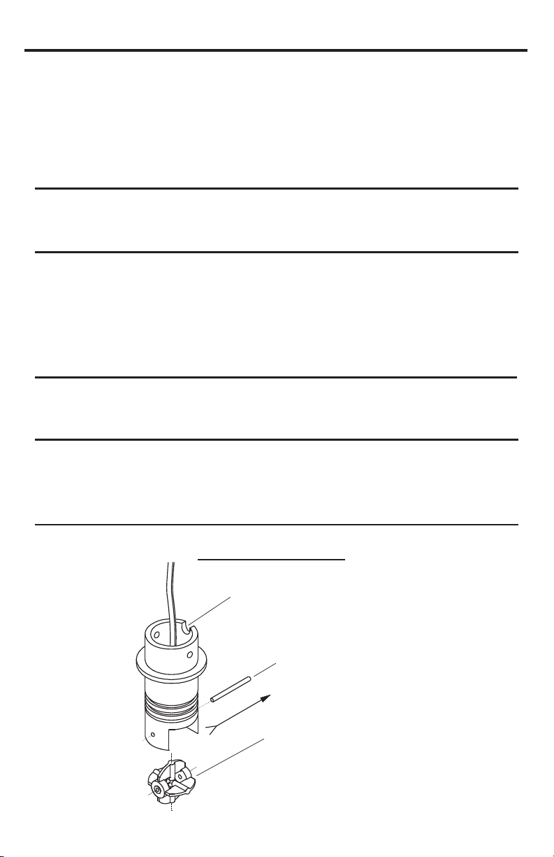
Paddle Removal
Step 1: Locate notch
on the sensor body.
Step 2: Push shaft out in
the arrow pointing Direction.
Arrow
Direction
Step 3: Replace the paddle,
then press shaft back into
place in the Opposite
direction.
Fig. 13
Page 16
Page 16
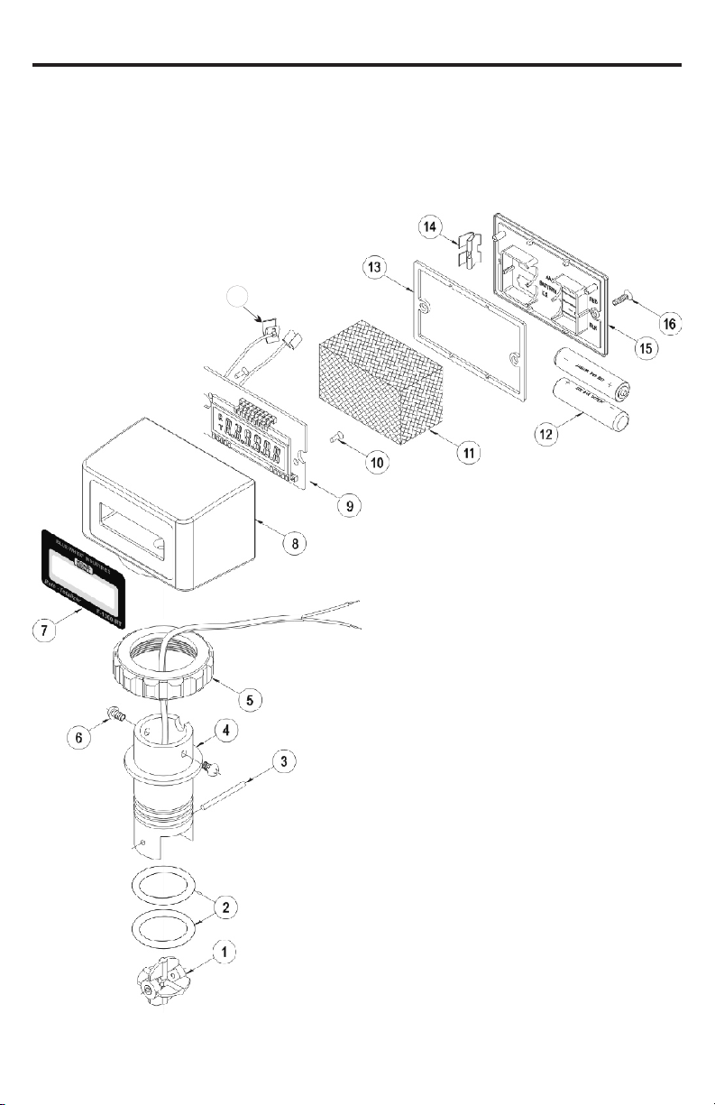
Item
Part#
Description
Qty
1
70000-783
Paddle assembly PVDF
1290003-021
O-ring 022 Viton E60
2390007-589
Axle PVDF
1
90007-567
Axle Hastelly
1
76000-845
Axle Titanium
1
4
71000-238
Sensor body assembly F-100 no paddle
1
5
91001-280
Union Nut
1
6
90011-080
Screw #6 x .37 PH Pan B 18/8
2790012-198
Label F-1000-RB GPM
1
90012-199
Label F-1000-RB GPH
1
90012-200
Label F-1000-RB LPM
1
90012-201
Label F-1000-RB LPH
1
90012-2023Label F-1000-RB M H
1
90012-221
Label F-1000-TB overlay
1
90012-220
Label F-1000-RT overlay
1876001-187
Housing F-1000
1
9
RBC-pipe-units
Circuit board for model RB. Must specify pipe
1
TBC-pipe-units
Circuit board for model TB. Must specify pipe
1
RTC-pipe-units
Circuit board for model RT. Must specify pipe
1
10
90011-169
Screw #4 .25 Phil Pan “A”
1
11
90013-260
Foam pad 1.25 x 1.25 x 2.25
11290008-318
Battery each AAA
21390006-590
Gasket F-1000
1
14
90008-319
Battery clip F-1000
1
15
90002-203
Rear plate F-1000
11690011-113
Screw #4 .50 Phil oval “A”
2
17
90010-241
Battery Connector
1
9.0 F-1000 PARTS LIST
17
F-1000 F-1000
Page 17

Page 17
Item
Part#
Description
Qty
1
70000-783
Paddle assembly PVDF
1290003-021
O-ring 022 Viton E60
2390007-589
Axle PVDF
1
90007-567
Axle Hastelly
1
76000-845
Axle Titanium
1
4
71000-238
Sensor body assembly F-100 no paddle
1
5
91001-280
Union Nut
1
6
90011-080
Screw #6 x .37 PH Pan B 18/8
2790012-198
Label F-1000-RB GPM
1
90012-199
Label F-1000-RB GPH
1
90012-200
Label F-1000-RB LPM
1
90012-201
Label F-1000-RB LPH
1
90012-2023Label F-1000-RB M H
1
90012-221
Label F-1000-TB overlay
1
90012-220
Label F-1000-RT overlay
1876001-187
Housing F-1000
1
9
RBC-pipe-units
Circuit board for model RB. Must specify pipe
1
TBC-pipe-units
Circuit board for model TB. Must specify pipe
1
RTC-pipe-units
Circuit board for model RT. Must specify pipe
1
10
90011-169
Screw #4 .25 Phil Pan “A”
1
11
90013-260
Foam pad 1.25 x 1.25 x 2.25
11290008-318
Battery each AAA
21390006-590
Gasket F-1000
1
14
90008-319
Battery clip F-1000
1
15
90002-203
Rear plate F-1000
11690011-113
Screw #4 .50 Phil oval “A”
2
17
90010-241
Battery Connector
1
Page 18
Page 18
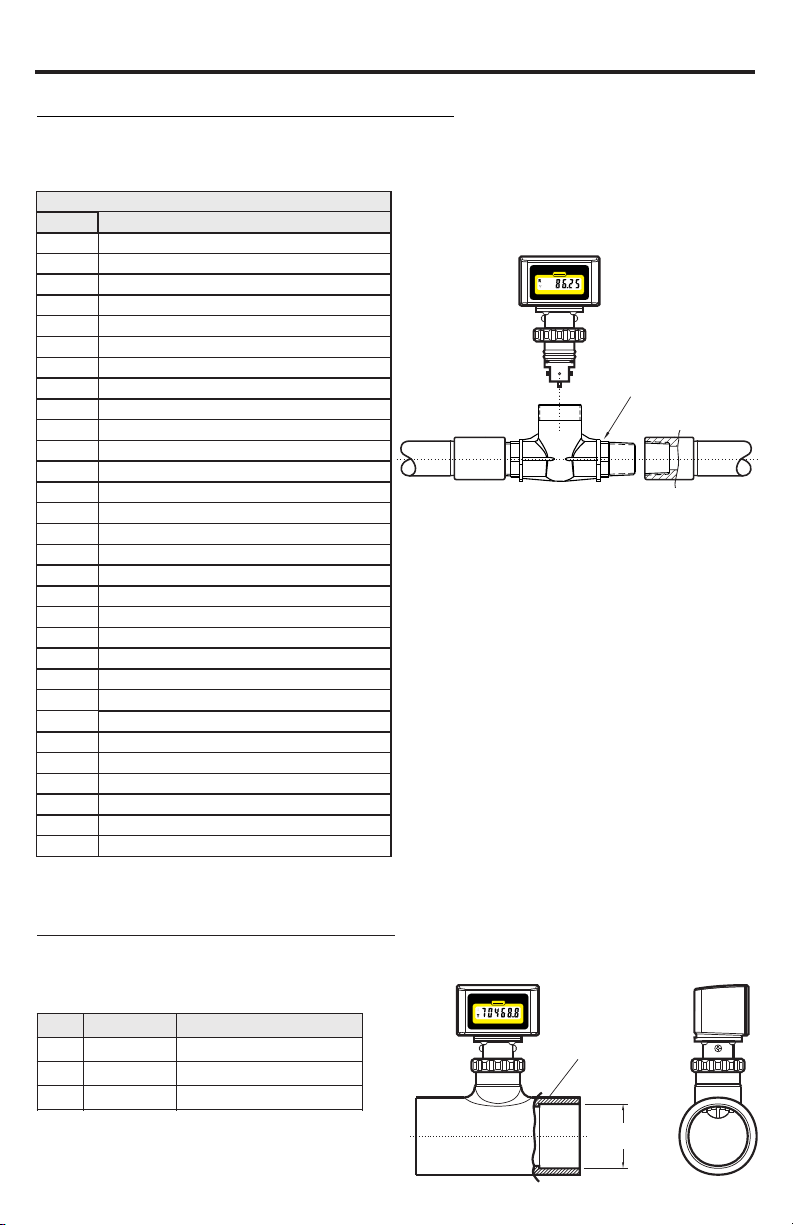
ITEM
PART NO.
DESCRIPTION
1
76000-978
1.0” TEE FITTING - PVC
76000-975
1.5” TEE FITTING - PVC
76000-976
2.0” TEE FITTING - PVC
MOLDED IN-LINE BODY PARTS LIST
F-1000
Complete Kit Ordering NumbersComplete Kit Ordering Numbers
Machined In-Line Pipe Fittings - U.S. (IPS) F/NPT
Molded In-Line Pipe Fittings - U.S. (IPS) M/NPT
Kit No
38M1
38M2
38F1
38F2
50M1
50M2
50F1
50F2
75M1
75M2
75F1
75F2
10M1
10M2
10F1
10F2
15M1
15M2
15M3
15F1
15F2
15F3
20M1
20M2
20M3
20M4
20F1
20F2
20F3
20F4
3/8” MPT .800 - 8.000 GPM - PP
3/8” MPT .400 - 4.000 GPM - PP
3/8” MPT .800 - 8.000 GPM - PVDF
3/8” MPT .400 - 4.000 GPM - PVDF
1/2” MPT 2.00 - 20.00 GPM - PP
1/2” MPT .500 - 5.000 GPM - PP
1/2” MPT 2.00 - 20.00 GPM - PVDF
1/2” MPT .500 - 5.000 GPM - PVDF
3/4” MPT 3.00 - 30.00 GPM - PP
3/4” MPT .800 - 8.000 GPM - PP
3/4” MPT 3.00 - 30.00 GPM - PVDF
3/4” MPT .800 - 8.000 GPM - PVDF
1” MPT 5.00 - 50.00 GPM - PP
1” MPT 2.00 - 20.00 GPM - PP
1” MPT 5.00 - 50.00 GPM - PVDF
1” MPT 2.00 - 20.00 GPM - PVDF
1-1/2” MPT 4.00 - 40.00 GPM - PP
1-1/2” MPT 6.00 - 60.00 GPM - PP
1-1/2” MPT 10.0 - 100.0 GPM - PP
1-1/2” MPT 4.00 - 40.00 GPM - PVDF
1-1/2” MPT 6.00 - 60.00 GPM - PVDF
1-1/2” MPT 10.0 - 100.0 GPM - PVDF
2” MPT 4.00 - 40.00 GPM - PP
2” MPT 6.00 - 60.00 GPM - PP
2” MPT 10.0 - 100.0 GPM - PP
2” MPT 20.0 - 200.0 GPM - PP
2” MPT 4.00 - 40.00 GPM - PVDF
2” MPT 6.00 - 60.00 GPM - PVDF
2” MPT 10.0 - 100.0 GPM - PVDF
2” MPT 20.0 - 200.0 GPM - PVDF
Description
Description
Complete kits include:
1) Molded inline body fitting
1) Instruction manual
®
BLUE-WHITE INDUSTRIES
MODE
RESET
GALLONS PER MINUTE
F-1000-RTRate - Totalizer
Pipe Fitting
MOLDED PVC TEE PARTS LIST
Replacement Tee Part Numbers
®
BLUE-WHITE INDUSTRIES
MODE
RESET
GALLONS PER MINUTE
F-1000-RBFlow Rate Meter
F-1000-RTRate - Totalizer
1
Nominal
Pipe Size
Page 19
F-1000
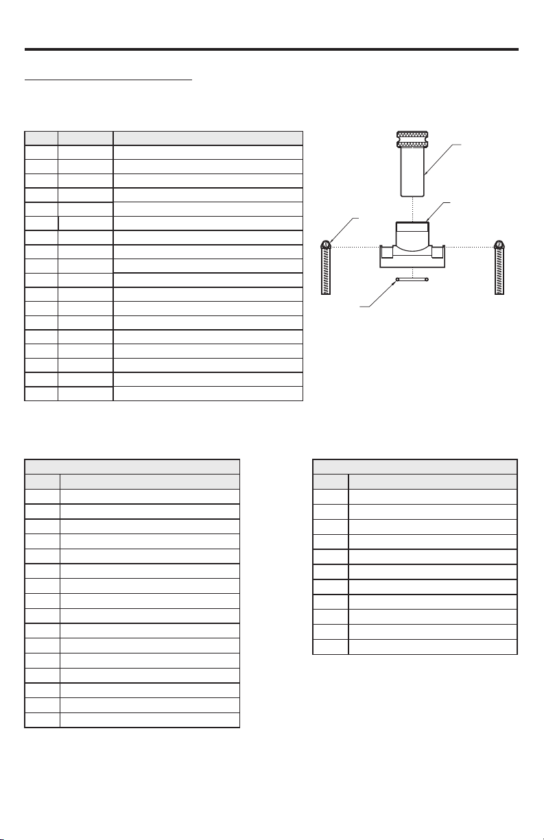
SADDLE PARTS LIST
Replacement Part Numbers
Page 19
Description
Alignment tool
Saddle, 1-1/2” pipe (50mm)
Saddle, 2” pipe (63mm)
Saddle, 3” pipe (90mm)
Saddle, 4” pipe (110mm)
Saddle, 6” pipe (160mm)
Saddle, 8” pipe (200mm)
Saddle, 10” & 12” pipe
Hose-Clamp #28 for 1-1/2” pipe
Hose-Clamp #40 for 2” pipe
Hose-Clamp #52 for 3” pipe
Hose-Clamp #72 for 4” pipe
Hose-Clamp #116 for 6” pipe
Hose-Clamp #152 for 8” pipe
Hose-Clamp #188 for 10” pipe
Hose-Clamp #224 for 12” pipe
O-ring / Viton for 1-1/2”, 2”, 3”
O-ring / Viton for 4”, 6”, 8”, 10”, 12”
®
®
90007-830
1
91001-115
2
91001-114
91001-116
76100-087
76100-088
76100-089
76100-139
90008-010
3
90008-137
90008-015
90008-018
90008-019
90008-020
90008-348
90008-349
90003-108
4
90003-114
Part No.Item
Complete Kit Ordering Numbers
U.S. (IPS) Pipe Saddle Fittings
Kit No
1-1/2” IPS pipe, schedule 40, PVDF
15K4
1-1/2” IPS pipe, schedule 80, PVDF
15K8
20K4
2” IPS pipe, schedule 40, PVDF
2” IPS pipe, schedule 80, PVDF
20K8
30K4
3” IPS pipe, schedule 40, PVDF
30K8
3” IPS pipe, schedule 80, PVDF
40A4
4” IPS pipe, schedule 40, PVC
40A8
4” IPS pipe, schedule 80, PVC
60A4
6” IPS pipe, schedule 40, PVC
60A8
6” IPS pipe, schedule 80, PVC
8” IPS pipe, schedule 40, PVC
80A4
80A8
8” IPS pipe, schedule 80, PVC
100A4
10” IPS pipe, schedule 40, PVC
100A8
10” IPS pipe, schedule 80, PVC
120A4
12” IPS pipe, schedule 40, PVC
120A8
12” IPS pipe, schedule 80, PVC
Description
1
2
3
4
Metric (DIN 8062) Pipe Saddle Fittings
Kit No
50mm Metric pipe, Pn10, PVDF
05K0
05K6
50mm Metric pipe, Pn16, PVDF
06K0
63mm Metric pipe, Pn10, PVDF
06K6
63mm Metric pipe, Pn16, PVDF
90mm Metric pipe, Pn10, PVDF
09K0
09K6
90mm Metric pipe, Pn16, PVDF
110mm Metric pipe, Pn10, PVC
11A0
11A6
110mm Metric pipe, Pn16, PVC
16A0
160mm Metric pipe, Pn10, PVC
16A6
160mm Metric pipe, Pn16, PVC
20A0
200mm Metric pipe, Pn10, PVC
Description
Complete kits include:
1) Saddle fitting
2) Pipe clamps
3) O-ring seal
1) Installation alignment tool
1) Instruction manual
1) Union nut
Page 20

BLUE-WHITE INDUSTRIES
LIMITED WARRANTY
FLOWMETERS are warranted to be free of defects in material and workmanship
for up to 12 months from the date of factory shipment. Warranty coverage is limited to
repair or replacement of the defective flowmeter only. Blue-White Industries does not
assume responsibility for any other damage that may occur.
This warranty does not cover damage to the flowmeter that results from misuse or
alterations, nor damage that occurs as a result of: meter misalignment, improper
installation, over tightening, use of non- recommended chemicals, use of nonreccomended adhesives or pipe dopes, excessive heat or pressure, or allowing the
meter to support the weight of related piping. Flowmeters are tested and calibrated
with water only. Although meters may be suitable for other chemicals, Blue-White
cannot guarantee their suitability.
Flowmeters are repaired at the factory only. Call or write the factory to receive a
Return Authorization Number, carefully pack the flowmeter to be returned, including a
brief description of the problem. Note the RA number on the outside of the carton.
Prepay all shipping costs. The factory does not accept COD Shipments. Damage that
occurs during shipping is the responsibility of the sender.
We are not satisfied
until you are!
Users of electrical and electronic equipment (EEE) with the WEEE marking per Annex IV of
the WEEE Directive must not dispose of end of life EEE as unsorted municipal waste, but
use the collection framework available to them for the return, recycle, recovery of WEEE
and minimize any potential effects of EEE on the environment and human health due to the
presence of hazardous substances. The WEEE marking applies only to countries within the
European Union (EU) and Norway. Appliances are labeled in accordance with European
Directive 2002/96/EC.
Contact your local waste recovery agency for a Designated Collection Facility in your area.
ISO 9001:2015
CERTIFIED
80000-335
Blue-White
REV. 10 20210803
Industries, Ltd.
Industries, Ltd.
®
URL: www.Blue-White.com
E-mail: [email protected]
MADE IN THE
USA
Phone: 714-893-8529
Fax: 714-894-0149
 Loading...