

Page 1

.
Electromagnetic Flow Meter
FMG90B Series
Page 2

- 2 -
Page 3

FMG90B Series
Copyright notice:
The reproduction, distribution and utilization of this operating manual as well as the communication of
its contents to others without express authorization is prohibited. Offenders will be held liable for the
payment of damages. All rights reserved in the
Table of contents page
0 About this operating manual ...................................................................................... 4
1 Device description ..................................................................................................... 5
1.1 Delivery, unpacking and accessories ...................................................................... 5
1.2 Intended use............................................................................................................ 6
1.3 Exclusion of liability ................................................................................................. 6
2 Safety instructions ..................................................................................................... 7
3 Construction and function .......................................................................................... 8
4 Installation of FMG90B .............................................................................................. 9
4.1 Installation instructions ............................................................................................ 9
4.2 Assembly ............................................................................................................... 10
5 Electrical connection ................................................................................................ 11
5.1 Wirings .................................................................................................................. 12
6 Commissioning and measuring operation ............................................................... 13
6.1 Commissioning ...................................................................................................... 13
6.2 Switching on and off .............................................................................................. 13
6.3 Measuring operation .............................................................................................. 13
7 Maintenance and cleaning ....................................................................................... 14
8 Disassembly and disposal ....................................................................................... 15
9 Technical data ......................................................................................................... 16
9.1 Characteristics FMG90B ....................................................................................... 16
9.2 Materials table ....................................................................................................... 17
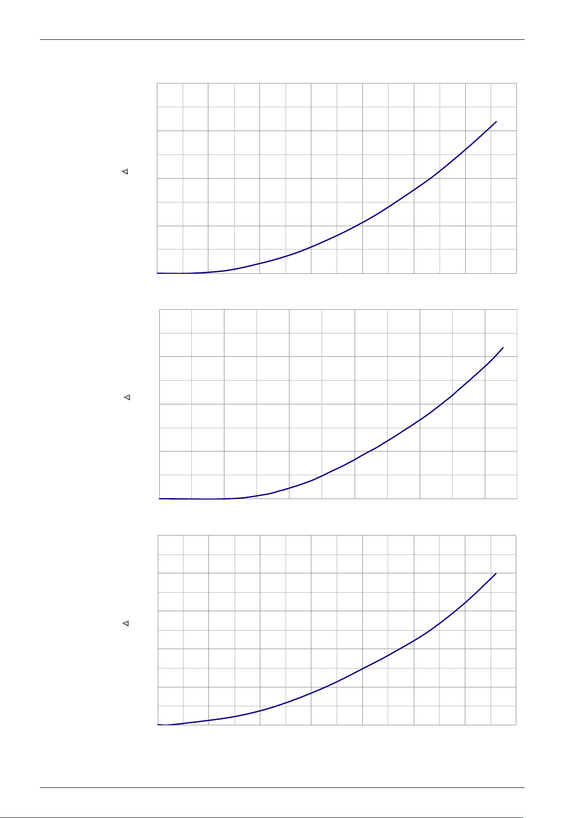
9.3 Pressure drop ........................................................................................................ 18
9.4 Dimensions............................................................................................................ 20
Technical changes reserved - 3 -
event of the grant of a patent, utility model or design.
Page 4
About this operating manual Series FMG90B
e-mail: [email protected]
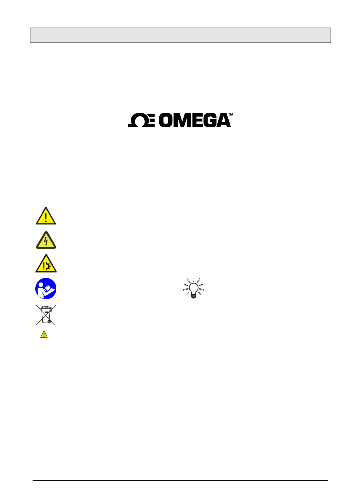
WARNING! / CAUTION! Risk of injury!
cause considerable damage to property.
CAUTION! Material damage!
damage.
NOTICE!
NO DOMESTIC WASTE!
Check the specified points or notices.
0 About this operating manual
• The operating manual is aimed at specialists and semi-skilled personnel.
• Before each step, read through the relevant advice carefully and keep to the specified
order.
• Thoroughly read and understand the information in the section “Safety instructions”.
If you have any problems or questions, please contact your supplier or contact us directly
at:
omega.com
Tel: (203) 359-1660
Hazard signs and other symbols used:
This sign indicates dangers that cause personal injuries that can lead to health defects or
CAUTION! Electric current!
This sign indicates dangers which could arise from handling of electric current.
This sign indicates actions which could lead to possible damage to material or environmental
ADHERE TO OPERATING MANUAL!
The device must not be disposed of
together with domestic waste.
Pay attention to and comply with
information that is marked with this symbol.
Follow the specified instructions and steps.
Adhere to the given order.
This symbol indicates important notices,
tips or information.
Reference to another section, document or
source.
• Item.
- 4 -
Page 5
FMG90B Series Device description
1 Device description
The FMG90B series from Omega is a flow sensor without moving parts. The measurement is
performed using magnetic induction.
The FMG90B is used for measuring or metering water and electrically conductive fluids. The
compact design and independence from the intake and discharge sections allows the
FMG90B to be used under a variety of conditions.
Versions:
The FMG90B is available in different inner diameters from 0.12 in to 0.98 in.
Type plate:
You can find the type plate on the back of the FMG90B.
It contains the most important technical data.
1.1 Delivery, unpacking and accessories
All units have been carefully checked for their operational reliability before shipment.
Immediately after receipt, please check the outer packaging for damages or any signs of
improper handling.
Report any possible damages to the forwarder and your responsible sales representative.
In such a case, state a description of the defect, the type and the serial number of the
device.
Report any in-transit damage immediately. Damage reported at a later date shall not be
recognized.
Unpacking:
Carefully unpack the unit to prevent any damage.
Check the completeness of the delivery based on the delivery note.
Scope of delivery:
1x FMG90B according to the order data.
1x Operating manual.
IMPORTANT!
Use the type plate to check if the delivered unit corresponds to your order.
In particular, for devices with electrical components, check to see if the correct power
supply voltage is specified.
Technical changes reserved - 5 -
Page 6
Device description FMG90B Series
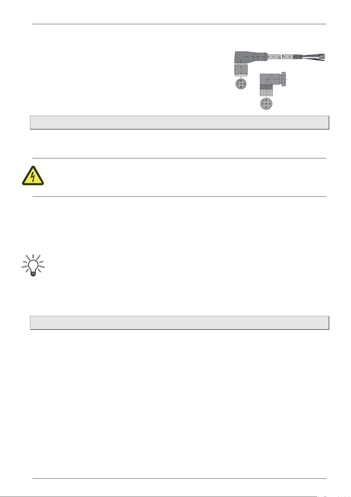
Accessories:
Connection cable with molded M12x1 coupling socket.
M12x1 coupling socket as component.
1.2 Intended use
The magnetic inductive flow sensor FMG90B must only be used for measuring and metering
liquids with a minimum conductivity of 20 μS/cm.
WARNING! No safety component!
The magnetic inductive flow sensor of the FMG90B series is no safety component in
accordance with Directive 2006/42/EC (Machine Directive).
Never use the FMG90B as a safety component.
The operational safety of the device supplied is only guaranteed by intended use. The
specified limits ( § 9 "Technical data") may under no circumstances be exceeded.
Before installing the device, check that the wetted materials of the device are compatible with
the media being used ( § 9 “Technical data”).
Measuring tube empty (or partially filled). / Conductivity too low.
The green LED may blink irregularly if the measuring tube of the FMG90B is empty or
partially filled or if the conductivity of the fluid being used is too low. Random pulses will
be present at the output, but they do not represent an actual flow.
Ensure that the measuring tube of the FMG90B is always completely filled
( § 4.1 "Installation instructions").
Ensure that the conductivity of the fluid is at least 20 μS/cm.
1.3 Exclusion of liability
We accept no liability for any damage or malfunctions resulting from incorrect installation,
inappropriate use of the device or failure to follow the instructions in this operating manual.
- 6 -
Page 7
FMG90B Series Safety instructions
2 Safety instructions
Before you install the FMG90B, read through this operating manual carefully. If the
instructions contained within it are not followed, in particular the safety guidelines, this could
result in danger for people, the environment, and the device and the system it is connected
to.
The FMG90B corresponds to the state-of-the-art technology. This concerns the accuracy, the
operating mode and the safe operation of the device.
In order to guarantee that the device operates safely, the operator must act competently and
be conscious of safety issues.
OMEGA provides support for the use of its products either personally or via relevant
literature. The customer verifies that our product is fit for purpose based on our technical
information. The customer performs customer- and application-specific tests to ensure that
the product is suitable for the intended use. With this verification all hazards and risks are
transferred to our customers; our warranty is not valid.
Qualified personnel:
The personnel who are charged for the installation, operation and maintenance of the
FMG90B must hold a relevant qualification. This can be based on training or relevant
tuition.
The personnel must be aware of this operating manual and have access to it at all times.
The electrical connection should only be carried out by a fully qualified electrician.
General safety instructions:
In all work, the existing national regulations for accident prevention and safety in the
workplace must be complied with. Any internal regulations of the operator must also be
complied with, even if these are not mentioned in this manual.
Degree of protection according to EN 60529:
Please ensure that the ambient conditions at the site of use does not exceed the
requirements for the stated protection rating ( § 9 "Technical data").
Prevent freezing of the medium in the device with appropriate measures.
Only use the FMG90B if it is in perfect condition. Damaged or faulty devices must be
checked without delay and, if necessary, replaced.
When fitting, connecting and removing use only suitable appropriate tools.
Do not remove or obliterate type plates or other markings on the device, as otherwise the
warranty is rendered null and void.
Special safety instructions:
Crystallizing liquids:
Liquids which crystallize when dried out can cause a malfunction of the FMG90B.
Make sure that the FMG90B is not run dry.
Prevent the crystallization of the fluid in the device by taking appropriate measures.
Further warnings that are specifically relevant to individual operating procedures or activities
can be found at the beginning of the relevant sections of this operating manual.
Technical changes reserved - 7 -
Page 8
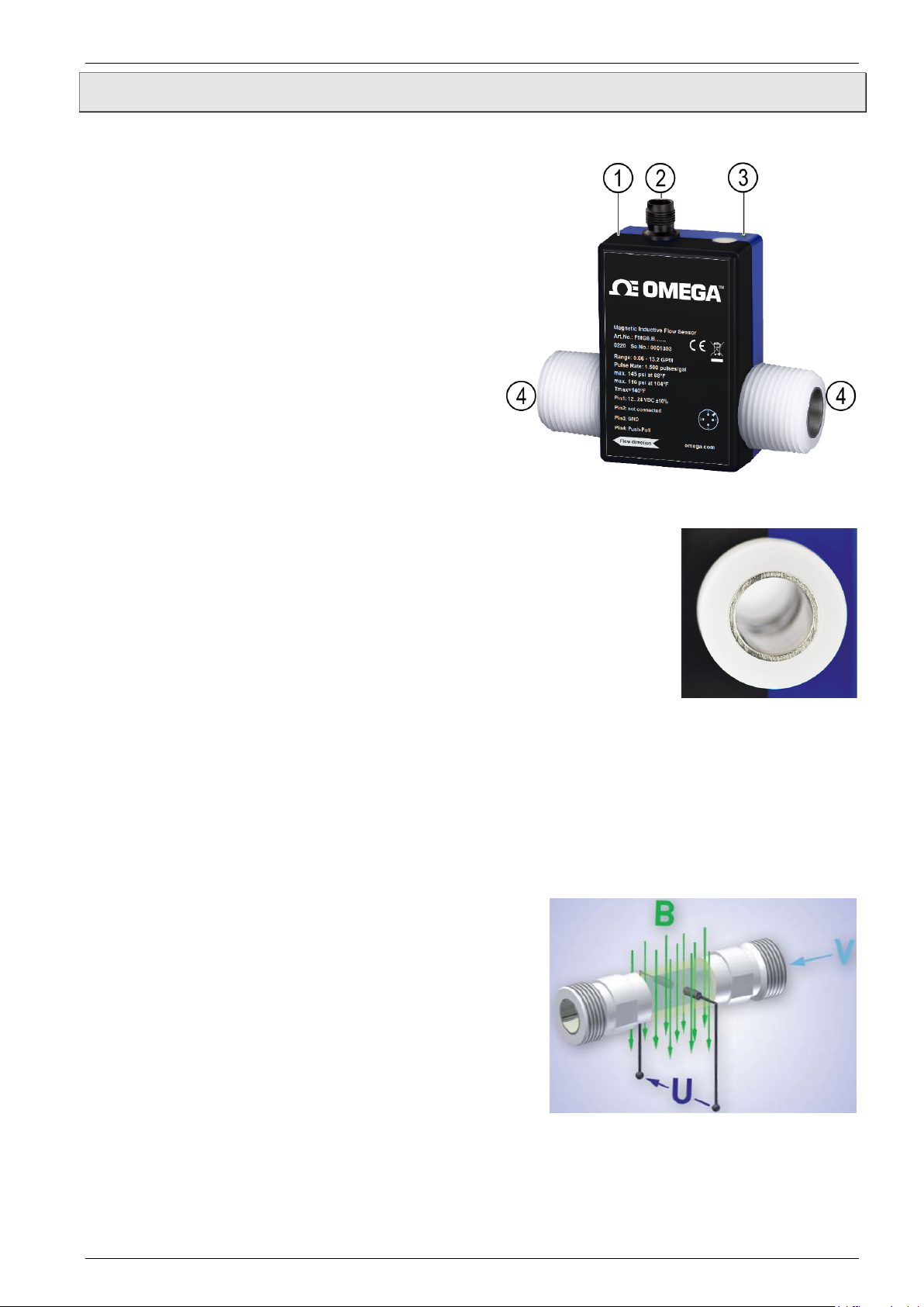
Construction and function FMG90B Series
3 Construction and function
Components:
Housing:
The Housing consists of plastic and has the
IP65 degree of protection.
Electrical connection:
The electrical connection is made via 4-pin
plug M12x1.
Operation / flow indicator LED.
Process connection:
The process connections are available in
different sizes.
Construction:
The measuring tube with its grounding sleeves and electrodes passes
through the housing and forms the external process connection of the
FMG90B.
A magnetic field for the measurement process is generated inside the
housing, which also contains the sensor and signal conditioning
circuitry.
The two stainless steel electrodes are located in the middle of the
measuring tube between the grounding sleeves.
The FMG90B does not need any moving parts to make measurements. The inside of the
measuring tube is completely open, allowing the fluid to flow unhindered through the
measuring tube.
Function:
The magnetic inductive flow sensor functions according to the induction principle. A DC
voltage is generated by the movement of a conductor in a magnetic field:
The measuring tube of the FMG90B is located in a
magnetic field (B).
An electrically conductive medium (V) flows through
the measuring tube. The positive and negative charge
carriers are oppositely deflected.
A voltage (U) is generated at right angles to the
magnetic field, which is picked up by the two
electrodes.
Thereby, the induced voltage is proportional to the
average flow velocity of the liquid.
The electronics of the FMG90B converts the induced voltage into a flow-proportional
frequency signal.
- 8 -
Page 9
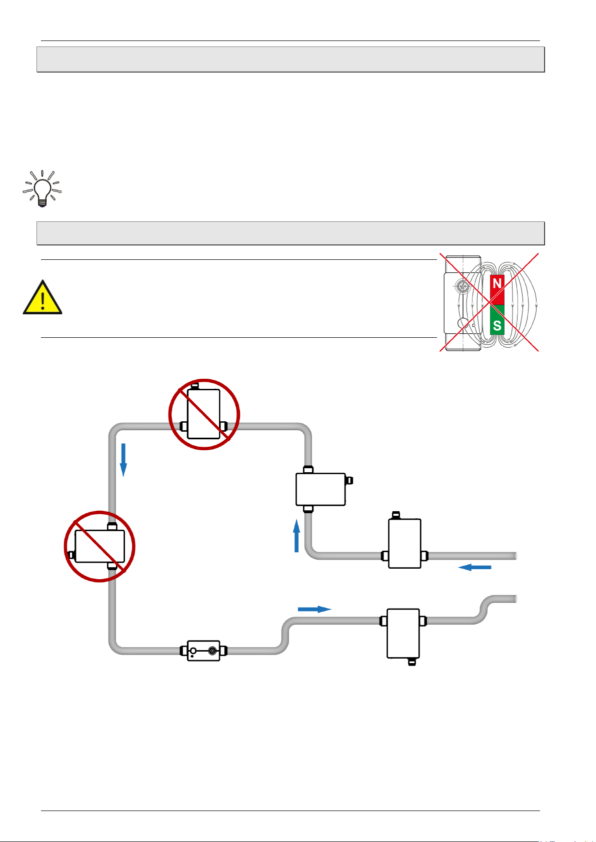
FMG90B Series Installation of FMG90B
Bubble-formation / run empty possible
Dirt deposits
possible
Run empty
possible
Dirt deposits
possible
4 Installation of FMG90B
Before installing, check that
the wetted materials of the device are suitable for the media being used
( § 9 “Technical data”).
the equipment is switched off and is in a safe and de-energized state.
the equipment is depressurized and has cooled down.
SUITABLE TOOLS:
Use only suitable tools of the correct size.
4.1 Installation instructions
CAUTION! Risk of malfunction due to external magnetic fields!
Magnetic fields close to the device can cause malfunctions and
should be avoided.
Ensure that no external magnetic fields are present at the
installation site of the FMG90B.
• The FMG90B can always be installed anywhere along the pipeline.
However, straight sections of piping are preferable.
Technical changes reserved - 9 -
Page 10
Installation of FMG90B FMG90B Series
• Installation can occur in horizontal and vertical pipes. The flow sensor is only suitable for
application in completely filled pipe systems.
• As a matter of principle magnetic inductive flow sensors are widely independent from the
flow profile. An inlet section is not absolutely necessary.
To reach a most highly accuracy of the measurement, you should use straight inlet and
outlet sections according to the inner diameter. The inlet section has to be at least
10 x inner diameter; the outlet section 5 x inner diameter in order to achieve the specified
accuracy.
• The inlet and outlet sections and the gaskets must have the
same or a slightly larger inside diameter than the measuring
tube in order to achieve the specified accuracy.
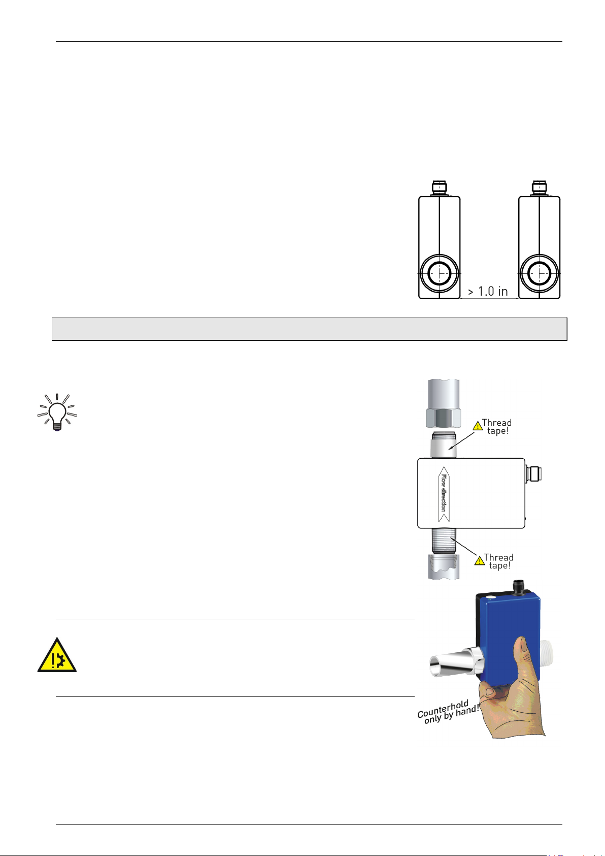
• If two or more FMG90B devices are used side by side,
maintain a separation of at least 1.0 in between adjacent
devices.
If adjacent devices are too close together, operation of both
devices may be impaired due to mutual interference.
4.2 Assembly
The FMG90B is installed directly into the pipeline. The compact design and light weight of the
unit make wall-mounting unnecessary.
IMPORTANT NOTICES:
• Only use suitable gaskets for installation.
• Observe the flow direction indicated on the type plate.
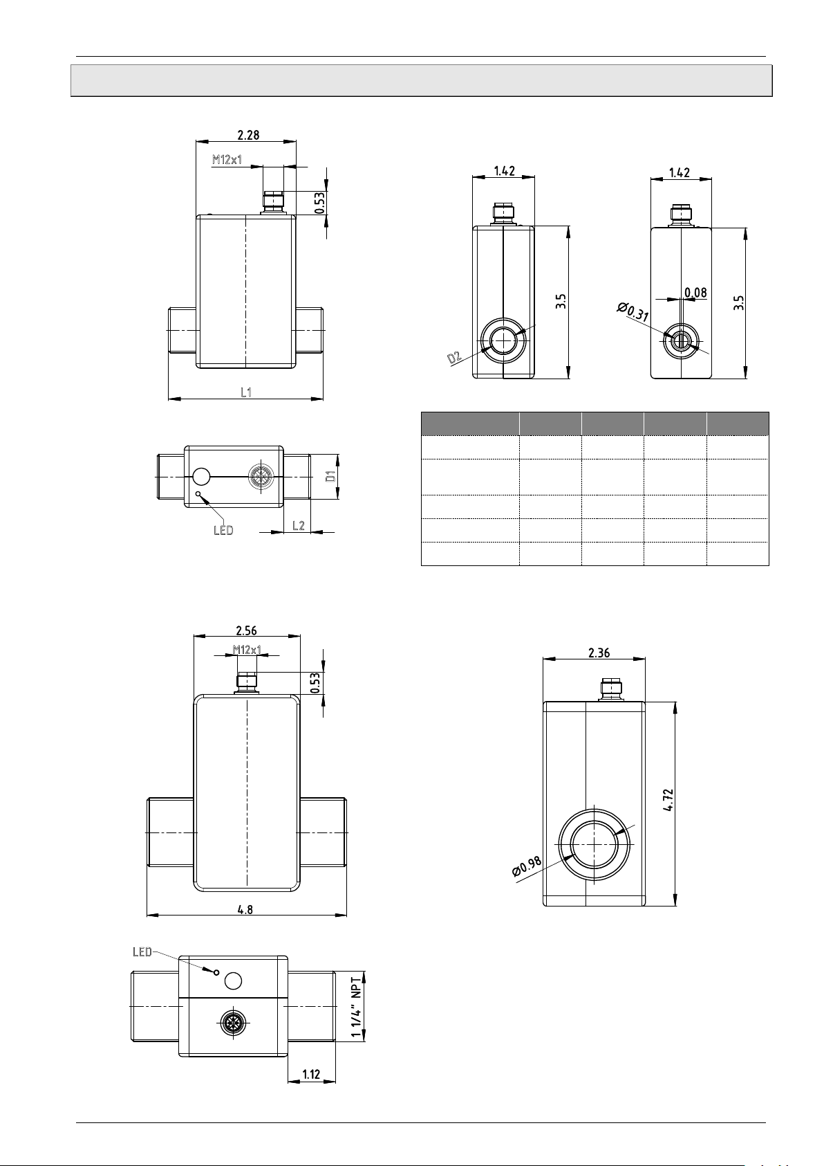
• Observe the mounting dimensions ( § 9.3 “Dimensions”).
Select an appropriate location for installation
( § 4.1 "Installation instructions").
To ensure the best possible measuring accuracy, a vertical
installation position with increasing flow is preferable (no
collecting of dirt deposits).
Wrap the FMG90B connections with 1 to 2 wraps of thread
tape (e.g. Teflon® tape). Wrap tape in a clockwise direction,
viewed form the end, leaving the first two threads uncovered.
Make sure the tape does not intrude into the flow path.
Attach the FMG90B with arrow pointed in the direction of flow.
The fittings should be screwed into FMG90B hand tight.
CAUTION! Material damage!
Maximum torque 3.7 ft lb.
While tightening, counter the FMG90B only by hand!
If you use an open-end or a pipe wrench, the FMG90B can
be damaged.
To tighten the FMG90B, use an open-end or a pipe wrench
for the fittings and only the hand for the FMG90B.
- 10 -
Page 11

FMG90B Series Electrical connection
5 Electrical connection
The electrical connection of the FMG90B is made via the 4-pin plug M12x1 at the top of the
housing.
The wiring of the FMG90B depends on the ordered version. A distinction is made between
frequency output or analog output and frequency output.
CAUTION! Electric current!
The electrical connection should only be carried out by a fully qualified electrician.
De-energize the electrical system before connecting the FMG90B.
Connection cable:
Suitable connection cables with molded coupling socket M12x1 are available in different
lengths as OMEGA accessories. The maximum permissible cable length is 10 m.
Connection 4-pin plug M12x1:
Screw the coupling socket of the connection cable to the plug of the FMG90B.
Tighten the knurled nut of the coupling socket with a maximum torque of 1 Nm.
Technical changes reserved - 11 -
Page 12
Electrical connection FMG90B Series
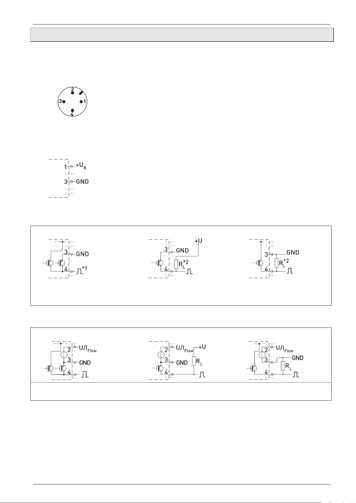
Pinout:
M12x1
Ensure that the maximum signal current of 25 mA is not exceeded.
Recommendation for resistance RL ~2.5 kΩ (12 V) or ~5 kΩ (24 V).
Ensure that the maximum signal current of 25 mA is not exceeded.
5.1 Wirings
Pinout:
The pinout differs according to the chosen configuration of the device.
Possible pinout:
Pin 1: +U
Pin 2: n. c. (not connected) / Analog U/I
Pin 3: GND
Pin 4: Frequency
Connect the connection cable according to your version and the pinout on the type plate.
Supply voltage:
B
FMG90B with frequency output:
Push-Pull:
NPN Open Collector:
PNP Open Collector:
*1: Push-Pull switching outputs of several FMG90B may not be connected in parallel.
*2: Recommendation Pull-Up / Pull-Down resistance RL ~2.5 kΩ (12 V) or ~5 kΩ (24 V).
Use of frequency and analog output
Push-Pull:
NPN Open Collector:
PNP Open Collector:
- 12 -
Page 13
FMG90B Series Commissioning and measuring operation
6 Commissioning and measuring operation
Before switching on the FMG90B for the first time, please follow the instructions in the
following section.
6.1 Commissioning
Check that
the FMG90B has been installed correctly and that all screw connections are sealed.
the electrical wiring has been connected properly.
the measuring system is vented by flushing.
6.2 Switching on and off
The FMG90B has no switch and cannot be switched on or off on its own. Switching on and
off is carried out by the applied supply voltage.
Switch on the supply voltage.
The green LED lights up. The FMG90B is ready and goes into measuring mode.
6.3 Measuring operation
In the measuring mode, the green LED flashes proportional to the measured flow.
For the human eye, the flashing is no longer visible from a frequency of ~30...40 Hz.
The green LED then seems to light up permanently.
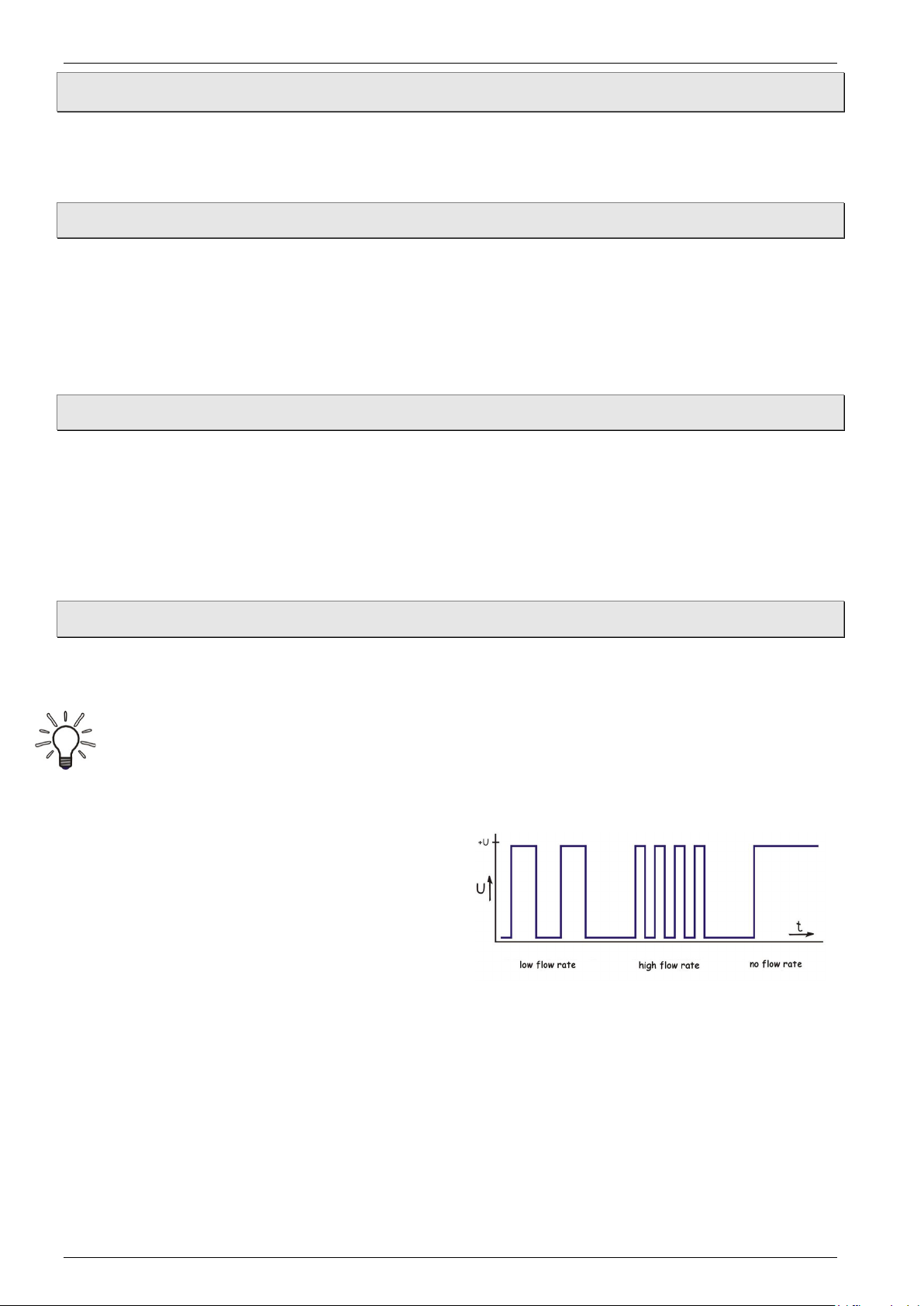
FMG90B with frequency output:
The FMG90B provides according to the
version a flow proportional NPN, PNP or
Push-Pull square wave signal.
The frequency of the pulse output changes
according to the flow ( Fig.).
FMG90B with analog output:
According to the configuration of the FMG90B, the analog output provides a voltage or
current signal.
This signal is proportional to the measured flow. You will find the scaling of the analog output
on the type plate.
Technical changes reserved - 13 -
Page 14

Maintenance and cleaning FMG90B Series
7 Maintenance and cleaning
Maintenance:
The FMG90B is maintenance-free and cannot be repaired by the user. In case of a defect,
the device must be replaced or sent back the manufacturer for repair.
CAUTION! Material damage!
When opening the device, critical parts or components can be damage.
Never open the device and perform any repair yourself.
Cleaning:
Clean the FMG90B with a dry or slightly damp lint-free cloth. Do not use sharp objects or
aggressive agents for cleaning.
- 14 -
Page 15
FMG90B Series Disassembly and disposal
8 Disassembly and disposal
CAUTION! Risk of injury!
Never remove the device from a plant in operation.
Make sure that the plant is shut down professionally.
Before disassembly:
Prior to disassembly, ensure that
the equipment is switched off and is in a safe and de-energized state.
the equipment is depressurized and has cooled down.
Disassembly:
Remove the electrical connectors.
Remove the FMG90B using suitable tools.
Disposal:
NO HOUSEHOLD WASTE!
The FMG90B consists of various different materials. It must not be disposed of with
household waste.
Take the FMG90B to your local recycling plant.
Technical changes reserved - 15 -
Page 16
Technical data FMG90B Series
Type
Measurement device characteristics
Flow range [gpm]
0.026…0.53
0.066…1.3
0.26…5.3
0.66…13.2
1.3…53
3.3…66
Accuracy*
±0.7 % of reading ±0.3 % of range
Repeatability
±1%
Output signal starting
from [gpm]
0.013
0.026
0.07
0.27
0.53
1.32
Max. flow rate [gpm]
0.66
1.58
6.6
15.8
63.4
79.2
Response time
< 100 ms
Indication
LED green, flow proportional flashing
Output signal characteristics
Frequency output:
- Pulse rate / K-Factor
[pulses/gal]
30000
15000
3000
1500
750
300
- Resolution [ml/pulse]
0.1
0.25
1.0
2.5
5.0
12.5
- Signal shape
Square wave signal • duty cycle 50:50
Push-Pull • NPN open collector • PNP open collector
- Signal current
≤ 100 mA
Electrical characteristics
Supply voltage
12...24 VDC (±10 %)**
Power consumption
Max 3.6 W
Electrical protection
measures
short-circuit proof • protected against polarity reversal
Electrical connection
4-pin plug M12x1
Degree of protection
(EN 60529)
IP 65 (only with a connected coupling)
Process variables
Medium to measure
Water and other conductive liquids
- Conductivity
> 20 μS/cm
- Temperature
14…140 °F (non-freezing)
Ambient temperature
41…140 °F
Storage temperature
5…140 °F
Inner diameter
0.12 in
0.31 x
0.08 in
0.31 in
0.55 in
0.71 in
0.98 in
Max. working pressure
(at … °F)
145 psi (68 °F) • 116 psi (104 °F) • 87 psi (140 °F)
higher pressure ratings on request
Process connection
- male thread
⅜” NPT
½” NPT
¾” NPT
1” NPT
1¼” NPT
9 Technical data
The technical data of customized versions may differ from the data in these instructions.
Please observe the information specified on the type plate.
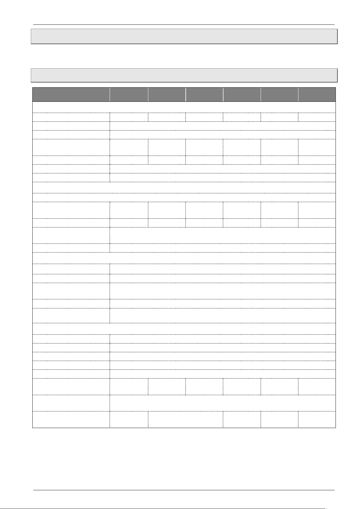
9.1 Characteristics FMG90B
FMG93B FMG96B FMG98B FMG915B FMG920B FMG925B
* test conditions: Water 73 °F
** Voltage output 0.5…10 V only available with 16…24 VDC
- 16 -
Page 17

FMG90B Series Technical data
Component
Material
Component-
wetted
Housing
ABS
Measuring tube
POM or PVDF (option)
X
Process connections
POM or PVDF (option)
X
O-ring
EPDM or FKM (option)
X
Electrodes and grounding
rings
Stainless steel 1.4404 or Hastelloy C®*
X
9.2 Materials table
* Available for FMG93B, FMG96B, FMG98B
Technical changes reserved - 17 -
Page 18
Technical data FMG90B Series
FMG93B
FMG96B
FMG98B
0
.0
0.5
1.0
1.5
2.0
2.5
3.0
0 0.1 0.2 0.3 0.4 0.5 0 .6
Pressure drop ∆p [psi]
Flo w ra te Q [GP M]
US version
0.0
0.5
1.0
1.5
2.0
2.5
0 0.25 0.5 0.75 1 1.25 1.5
P
ressure drop ∆p [psi]
Flo w rate Q [GP M]
0.00
0.50
1.00
1.50
0 1 2 3 4 5 6
Pressure dro p ∆p [psi]
Flo w rate Q [GP M]
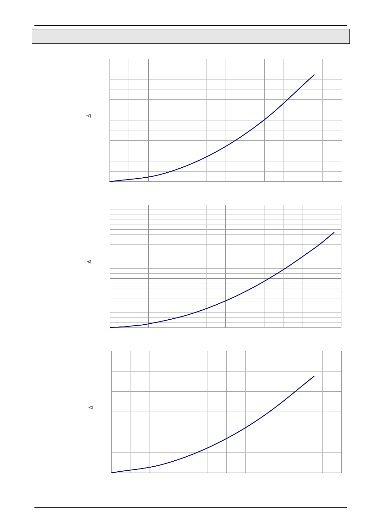
9.3 Pressure drop
- 18 -
Page 19
FMG90B Series Technical data
FMG920B
FMG925B
0.000
0.125
0.250
0.375
0.500
0 2 4 6 8 10 12 14
Pre
ssure drop ∆p [psi]
Flo w rate Q [GP M]
0.0
0.5
1.0
1.5
2.0
0 10 20 30 40 50
Pressure drop ∆p [psi]
Flo w rate Q [GP M]
0.0
0.1
0.2
0.3
0.4
0.5
0 10 20 30 40 50 60 70
Pre
ssure drop ∆p [psi]
Flo w rate Q [GP M]
FMG915B
Technical changes reserved - 19 -
Page 20
Technical data FMG90B Series
Type
L1
L2
D1
D2
FMG93B
Ø 0.31
x 0.08
FMG98B
FMG915B
FMG920B
3.54
0.63
1“ NPT
Ø 0.71
L1
M1
2
x1
D
2
D
1
L2
LED
M
1
2x
1
L
ED
9.4 Dimensions
FMG90B:
FMG96B
FMG925B:
3.35 0.51 ⅜“ NPT Ø 0.12
FMG96B
3.35 0.51
3.35 0.51 ½“ NPT Ø 0.31
3.54 0.63 ¾“ NPT Ø 0.55
½“ NPT
- 20 -
Page 21

FMG90B Series For your notes
For your notes
Technical changes reserved - 21 -
Page 22

For your notes FMG90B Series
For your notes
- 22 -
Page 23
Page 24

M5759/0220
 Loading...