

Page 1

`
Page 2

`
Toll-Free: 1-800-826-6342
Tel: (203) 359-1660
OMEGAnet
®
Online Service
omega.com
Servicing North America:
U.S.A.:
ISO 9001 Certified Stamford, CT 06907-0047
Omega Engineering, Inc., One Omega Drive, P.O. Box 4047
FAX: (203) 359-7700
Internet e-mail
e-mail: [email protected]
The information contained in this document is believed to be correct, but OMEGA accepts no liability for any
errors it contains, and reserves the right to alter specifications without notice.
Page 3

`
TABLE OF CONTENTS
1. UNPACKING the Optical Sensor Switch.
1.1 Inspect Package for External Damage
1.2 Unpack the Optical Sensor Switch.
1.3
Packing List………………………………………………………..1
1.4 Returning Merchandise for Repair
2. DESCRIPTION.
3. INSTALLATION.
3.1 Electrical Connections……………………………………………2
4. SPECIFICATIONS………………………………………………………
5. CE Compliance
6. OPERATING INSTRUCTIONS.
6.1 Sensor alignment.
6.2 DIP Switch Configuration.
7. TROUBLESHOOTING.
7.1 Common Conditions…………………………………………….
7.2 Troubleshooting Guide
7.3 Technical Assistance……………………………………………
APPENDIX 1 COMPONENT DIAGRAM.
................................................................................. 1
....................................................................................... 2
................................................................................ 4
........................................................... 5
................................................................... 5
.......................................................... 5
........................................................................ 6
............................................................ 7
........................................ 1
.................................... 1
......................................... 1
.......................................... 1
................................................. 8
4
6
7
APPENDIX 2 DIMENSIONAL DRAWINGS
APPENDIX 3 WARRANTY
............................................. 9
Page 4

`
Quantity
Desired Flow Meter with Hi-Lo
Sensors Installed
1
OSSM
1
Power Supply
Optional
Splitter
2
User’s Guide
1
1
UNPACKING THE Optical Sensor Switch
1.1
Inspect Package for External Damage
Your Optical Sensor Switch was carefully packed in a sturdy cardboard carton,
with anti-static cushioning materials to withstand shipping shock. Upon receipt,
inspect the package for possible external damage. In case of external damage to
the package contact the shipping company immediately.
1.2
Unpack the Optical Sensor Switch
Open the carton carefully from the top and inspect for any sign of concealed shipping damage. Please keep all packing and notify Omega Customer Service of
any damage.
When unpacking the instrument please make sure that you have all the items
indicated on the Packing List. Please report any shortages promptly.
1.3
1.4
Please contact the customer service representative at 1-800-826-6342 ext. 2208
for a Return Authorization Number (AR).
It is mandatory that any equipment returned for servicing be purged and
neutralized of any dangerous contents including but not limited to toxic, bacterially
infectious, corrosive or radioactive substances.
2.
The 150 mm Flow Meter with Hi-Lo Alarm Optical Sensor Switche is a noninvasive means for detection of a HI or LOW flow. This sensor is ideal for
signaling an alarm, cutoff valve, or other device when the float passes the
detector.
The Hi-Lo Optical Sensor Switch consists of the OSSM module and two selfcontained mini-slim photoelectric sensors (Thrubeam type). Every sensor has
a transmitter and receiver. Two sets of sensors are mounted on two solid carriers
on opposite sides of the flow tube. The float inside the flow tube is detected as
it passes across the beam of light. The sensors can be used to detect the float
passage beyond the set point of the sensor and can also be set to mo111 |
Pagenitor the float position at a specific level, signaling when the float is outside
of the range of the sensor light beam.
Packing List
Returning Merchandise for Repair
DESCRIPTION
1
Page 5
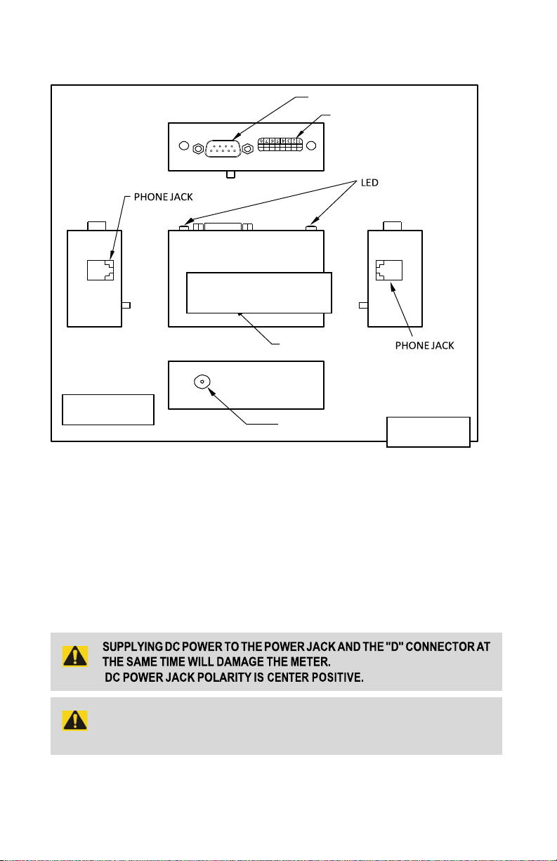
`
9-PIN D-CONNECTOR
RESET
POWER
WARNING: DO NOT CONNECT POWER SUPPLY WITH MORE
THAN 15VDC VOLTAGE
OPTICAL SENSOR SWITCH MODULE
High Flow
Low Flow
3. INSTALLATION
Figure 1: OSSM module
3. Electrical Connections
The Optical Sensor Switch gets a power through the OSSM module.
The module could be powered up either by a +12+15 VDC power supply with a
minimum current rating of 250 mA, or by the 9-pin D-connector (DB9M)
(Fig. 1) for momentary or latch operations.
3.1. Insert the LOW flow sensor’s plugs into the splitter, then the splitter’s plug into the module’s phone jack #1 (Fig. 1).
2
Page 6
`
3.2. Insert the HIGH flow sensor’s plugs into the splitter, then the splitter’s plug into the module’s phone jack #2 (Fig. 1).
3.3 Connect the power supply through the power jack (Fig. 1).
Or
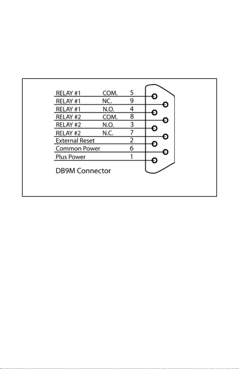
Attach the 9-pin D-connector to the module (fig. 1 & 2).
Figure 2: 9 Pin “D” Connector Configuration.
During the initial power up of the Optical Sensor Switch with no flow
conditions the red and green LED on the module will be “On”. This is an
indication that power is on and the sensors are ready for operation.
Both sensors will have 2 green lights “On” from each side of the flow meter.
Important notes:
In general, "D" Connector numbering patterns are standardized. There are, however, some connectors with nonconforming patterns and the numbering
sequence on your mating connector may or may not coincide with the numbering
sequence shown in our pin configuration table above. It is imperative that you
match the appropriate wires in accordance with the correct sequence regardless
of the particular numbers displayed on your mating connector.
Make sure power is OFF when connecting or disconnecting any cables in the system. The power input is protected by a 600 mA (medium time-lag) resettable fuse.
If a shorting condition or polarity reversal occurs, the fuse will cut power to the
valve circuit. Disconnect the power to the unit; remove the faulty condition, and
reconnect the power.
3
Page 7

`
MATERIALS OF
CONSTRUCTION:
END BLOCKS:
Aluminum or 316 Stainless Steel.
ELASTOMERS:
Buna & Viton (Aluminum), Viton (316 SS).
FLOW TUBE:
Borosilicate Glass.
:
+
12+15 VDC. Minimum current rating 250 mA
peak to peak max 100mV.
POWER CONSUMPTION:
Less than 200 mA. ACCURACY:
+/- 2% of full scale.
REPEATABILITY:
0.5% of full scale.
AMBIENT TEMPERATURE:
20-55 deg. C.
RESPONSE TIME:
0.5
milliseconds.
LIGHT IMMUNITY:
4 Element, point light source, red LED 650 nm
DRY CONTACT CLOSURES:
2 normally open, and normally closed relays (1A, 30VDC max.)
ALARM:
70 dB audible buzzer and/or visual LED
ALARM OPTIONS:
High, Low, or High/Low.
BUZZER:
User configurable, momentary or latch.
Reset button or remote through “D”-connector to disable relay
or buzzer (remote Reset is TTL compatible active Low).
The fuse will reset once the faulty condition has been removed.
Use of the Optical Sensor Switch in a manner other than that specified in this
manual may impair the protection provided by the equipment.
4. SPECIFICATIONS
POWER INPUT
RESET:
Environmental (per IEC 664): Installation Level II; Pollution Degree
CE Compliance
5.
Any model Optical Sensor Switch bearing a CE marking on it, is in compliance
with the below stated test standards currently accepted.
EMC Compliance with 89/336/EEC as amended;
Emission Standard: EN 55011:1991, Group 1, Class B
Immunity Standard: EN 55082 1:1992
4
Page 8

`
OPERATING INSTRUCTIONS
6.
6.1.
Sensor Alignments
Two sensors’ carriers can be set in any position along the flow meter tube.
WARNING: Do not install the sensors closer than 1/2” (10 mm) from one to another. Doing so may trigger a false alarm condition.
To set up the switches position:
-Loosen the 2 red thumbscrews;
-Slide the switch carrier to the desired position;
-Tighten the thumbscrews.
Stable operation indicator (green LED) turns on with a stable incoming
beam and with a stable blocked light. Output indicator (orange LED)
turns on when the beam from emitter is blocked by the float.
Each Optical Sensor Switch is shipped from the factory with the sensors
aligned and does not require additional adjustment of the focus distance even if
the flow tube was replaced or reinstalled (see p. 6.2).
6.2.
DIP switch configuration
The DIP switch, located near the 9-pin D-connector can be used to set up custom’s
settings separately for High and Low alarm.
In order to activate the sensor’s alarm the corresponding switch has to be installed
in the “On” position on the Configuration DIP switch (see Fig. 3). Each sensor
(High or Low) can be separately set for Momentary or Latch operation. In addition
the Relay and Buzzer can be configured individually.
As an example, if the SW1 is set to “On”: the High flow alarming (latching mode) is
active, then the green LED (on left side of the D-connector) and relay will be
energized in the LATCH mode. They will stay in the energized state without any
conditions (even if the flow rate changes and the sensor have become inactive)
until the RESET button is pressed or external RESET TTL signal is applied. If
momentary mode is set (DIP switch SW3 is set to “On”) the relay and green LED
will be energized only when the High flow sensor is active (Alarm Condition). The
same is true for the Buzzer settings.
All Switches “Off” position–Alarm is disabled (LED, Relays and Buzzer).
5
Page 9

`
HIGH ALARM
LOW ALARM
ACTION WHEN SWITCH IS “ON”
SW1
SW5
LED and Relay are On (LATCH)
SW2
SW6
BUZZER is On (LATCH)
SW3
SW7
LED and Relay are On momentary
SW4
SW8
BUZZER is On momentary
ALARM DIP SWITCH CONFIGURATION
“On”- pressed down “Off”-raised up
(FOLLOW SENSOR)
(FOLLOW SENSOR)
Figure 3: Optical Sensor DIP Switch Configuration.
7.
TROUBLESHOOTING
7.1.
Common Conditions
Your Optical Sensor Switch was thoroughly checked at numerous quality control
points during and after manufacturing and assembly operations. It was carefully
packed to prevent damage during shipment. Should you feel that the instrument is
not functioning properly please check for the following common conditions first:
Are all cables connected correctly?
Are there any leaks in the installation?
Is the power supply correctly selected according to requirements? When several
devices are used a power supply with appropriate current rating should be selected.
Were the connector pinouts matched properly? When interchanging with other
manufacturers' equipment, cables and connectors must be carefully wired for
correct pin configurations.
6
Page 10

`
O
N
.
1
7.2.
Troubleshooting Guide
INDICATION
No green LED
lights on
sensors.
Power supply off.
LIKELY REASON
Check connection of the
power supply.
SOLUTION
No connections between
sensors and splitter; no
connections between
splitter and OSSM
Buzzer or
2
Relay does not
work.
The sensor
3
not react on
passing float
(no orange LED)
7.3.
Technical Assistance
Repair personnel. Please call our Technical Assistance at 800 872 9436 ext.
2298. Please have your Serial Number and Model Number ready when you call.
does
Wrong configuration of the
DIP switch.
Pc board defect.
Sensor’s carrier is not
locked into the position
Check connection
between sensors,
splitters & the OSSM.
Make correct configuration of
the DIP switch according to
Figure 3.
Return to factory for
replacement.
Tighten the red thumbscrews
7
Page 11
`
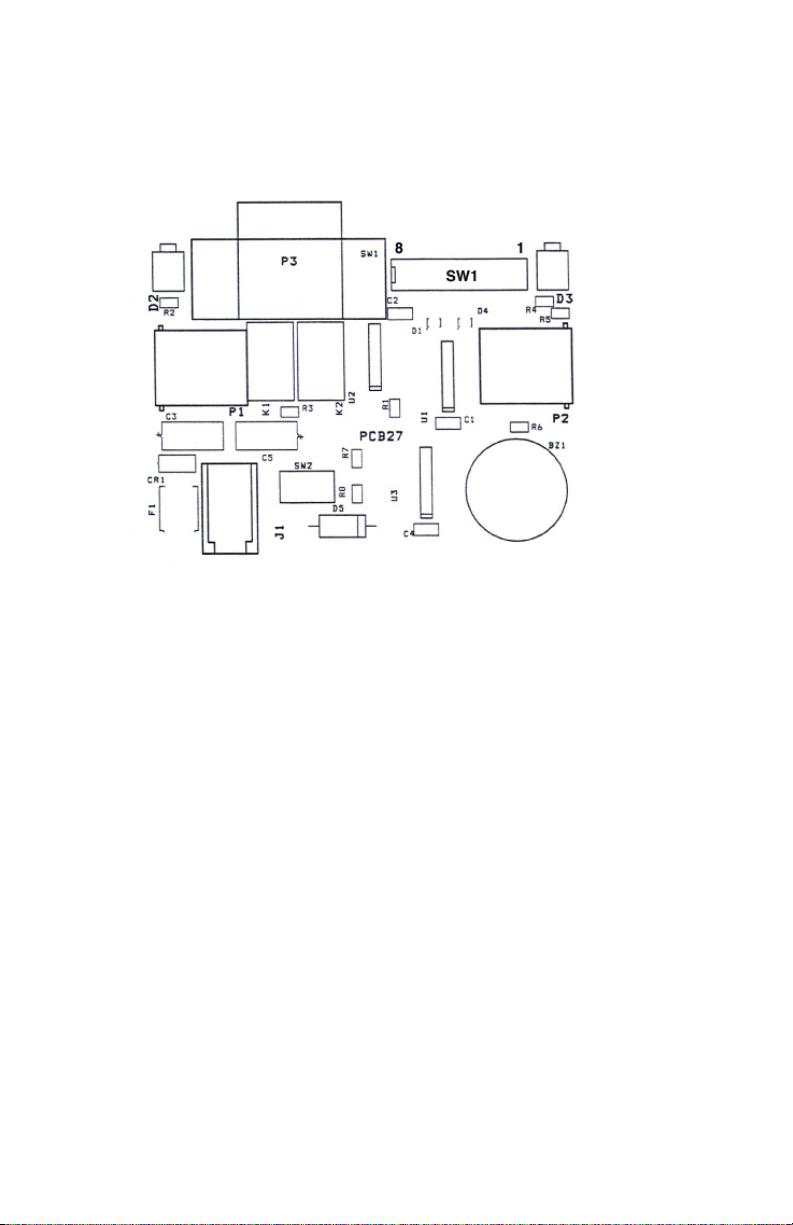
APPENDIX 1
COMPONENTS DIAGRAM
8
Page 12
`
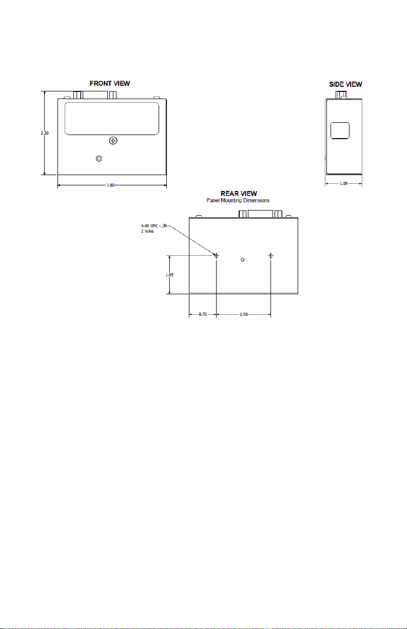
APPENDIX 2
DIMENSIONAL DRAWINGS
9
Page 13

`
WARRANTY/DISCLAIMER
OMEGA ENGINEERING, INC. warrants this unit to be free of defects in materials and
workmanship for a period of 13 months from date of purchase. OMEGA’s WARRANTY adds an
additional one (1) month grace period to the normal one (1) year product warranty to cover
handling and shipping time. This ensures that OMEGA’s customers receive maximum coverage
on each product.
If the unit malfunctions, it must be returned to the factory for evaluation. OMEGA’s Customer
Service Department will issue an Authorized Return (AR) number immediately upon phone or
written request. Upon examination by OMEGA, if the unit is found to be defective, it will be
repaired or replaced at no charge. OMEGA’s WARRANTY does not apply to defects resulting
from any action of the purchaser, including but not limited to mishandling, improper interfacing,
operation outside of design limits, improper repair, or unauthorized modification. This
WARRANTY is VOID if the unit shows evidence of having been tampered with or shows
evidence of having been damaged as a result of excessive corrosion; or current, heat, moisture
or vibration; improper specification; misapplication; misuse or other operating conditions
outside of OMEGA’s control. Components in which wear is not warranted, include but are not
limited to contact points, fuses, and triacs.
OMEGA is p
leased to offer suggestions on the use of its various products. However,
OMEGA neither assumes responsibility for any omissions or errors nor assumes liability for any
damages that result from the use of its products in accordance with information provided by
OMEGA, either verbal or written. OMEGA warrants only that the parts manufactured by the
company will be as specified and free of defects. OMEGA MAKES NO OTHER WARRANTIES OR
REPRESENTATIONS OF ANY KIND WHATSOEVER, EXPRESSED OR IMPLIED, EXCEPT THAT OF
TITLE, AND ALL IMPLIED WARRANTIES INCLUDING ANY WARRANTY OF MERCHANTABILITY
AND FITNESS FOR A PARTICULAR PURPOSE ARE HEREBY DISCLAIMED. LIMITATION OF
LIABILITY: The remedies of purchaser set forth herein are exclusive, and the total liability of
OMEGA with respect to this order, whether based on contract, warranty, negligence,
indemnification, strict liability or otherwise, shall not exceed the purchase price of the
component upon which liability is based. In no event shall OMEGA be liable for consequential,
incidental or special damages.
CONDITIONS: Equipment sold by OMEGA is not intended to be used, nor shall it be used: (1) as
a “Basic Component” under 10 CFR 21 (NRC), used in or with any nuclear installation or activity;
or (2) in medical applications or used on humans. Should any Product(s) be used in or with any
nuclear installation or activity, medical application, used on humans, or misused in any way,
OMEGA assumes no responsibility as set forth in our basic WARRANTY/DISCLAIMER language,
and, additionally, purchaser will indemnify OMEGA and hold OMEGA harmless from any liability
or damage whatsoever arising out of the use of the Product(s) in such a manner.
RETURN REQUESTS/INQUIRIES
Direct all warranty and repair requests/inquiries to the OMEGA Customer Service Department.
BEFORE RETURNING ANY PRODUCT(S) TO OMEGA, PURCHASER MUST OBTAIN AN AUTHORIZED
RETURN (AR) NUMBER FROM OMEGA’S CUSTOMER SERVICE DEPARTMENT (IN ORDER TO AVOID
PROCESSING DELAYS). The assigned AR number should then be marked on the outside of the return
package and on any correspondence.
The purchaser is responsible for shipping charges, freight, insurance and proper packaging to
prevent breakage in transit.
FOR WA
RRANTY RETURNS, please have the
following information available BEFORE
contacting OMEGA:
1.
Purchase Order number under which
the product was PURCHASED,
2.
Model and serial number of the product
under warranty, and
3.
Repair instructions and/or specific
problems relative to the product.
ON-WARRANTY REPAIRS, consult OMEGA
FOR N
for current repair charges. Have the following
information available BEFORE contacting OMEGA:
1. Purchase Order number to cover the
COST of the repair,
2.
Model and serial number of the product, and
3.
Repair instructions and/or specific problems
relative to the product.
OMEGA’s po licy is to make running changes, not model changes, whenever an improvement is possib le.
This affords our customers the latest in technology and engineering.
OMEGA is a registered trademark of OMEGA ENGINEERING, INC.
© Copyright 2009 OMEGA ENGINEERING, INC. All rights reserved. This document may not be copied, photocopie d, repro-
duced, translated, or reduced to any electronic medium or machine-readable form, in whole or in part, without the prior written consent of OMEGA ENGINEERING, INC.
Page 14

`
Where Do I Find Everything I Need for
Process Measurement and Control?
OMEGA…Of Course!
Shop online at omega.com
TEMPERATURE
Dv
Thermocouple, RTD & Thermistor Probes, Connectors, Panels & Assemblies
Dv
Wire: Thermocouple, RTD & Thermistor
Dv
Calibrators & Ice Point References
Dv
Recorders, Controllers & Process Monitors
Dv
Infrared Pyrometers
PRESSURE, STRAIN AND FORCE
Dv
Transducers & Strain Gages
Dv
Load Cells & Pressure Gages
Dv
Displacement Transducers
Dv
Instrumentation & Accessories
FLOW/LEVEL
Dv
Rotameters, Gas Mass Flowmeters & Flow Computers
Dv
Air Velocity Indicators
Dv
Turbine/Paddlewheel Systems
Dv
Totalizers & Batch Controllers
pH/CONDUCTIVITY
Dv
pH Electrodes, Testers & Accessories
Dv
Benchtop/Laboratory Meters
Dv
Controllers, Calibrators, Simulators & Pumps
Dv
Industrial pH & Conductivity Equipment
SM
DATA ACQUISITION
Dv
Data Acquisition & Engineering Software
Dv
Communications-Based Acquisition Systems
Dv
Plug-in Cards for Apple, IBM & Compatibles
Dv
Datalogging Systems
Dv
Recorders, Printers & Plotters
HEATERS
Dv
Heating Cable
Dv
Cartridge & Strip Heaters
Dv
Immersion & Band Heaters
Dv
Flexible Heaters
Dv
Laboratory Heaters
ENVIRONMENTAL MONITORING AND CONTROL
Dv
Metering & Control Instrumentation
Dv
Refractometers
Dv
Pumps & Tubing
Dv
Air, Soil & Water Monitors
Dv
Industrial Water & Wastewater Treatment
Dv
pH, Conductivity & Dissolved Oxygen Instruments
M-4059/1022
 Loading...