

Page 1
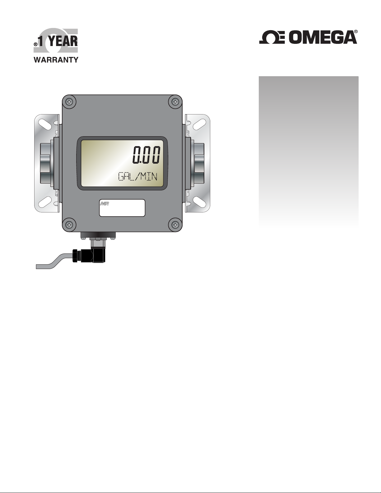
RUN
3500 PSI/241 BARS MAX
User’s Guide
Flow Transmitter
OIL
Shop online at
omega.com
e-mail: [email protected]
For latest product manuals:
www.omegamanual.info
SM
FLOW TRANSMITTER
MR Model
Page 2

omega.com [email protected]
Servicing North America:
U.S.A. Omega Engineering, Inc.
Headquarters: Toll-Free: 1-800-826-6342 (USA & Canada only)
Customer Service: 1-800-622-2378 (USA & Canada only)
Engineering Service: 1-800-872-9436 (USA & Canada only)
Tel: (203) 359-1660 Fax: (203) 359-7700
e-mail: [email protected]
For Other Locations Visit omega.com/worldwide
The information contained in this document is believed to be correct, but OMEGA accepts no liability for any errors it contains, and
reserves the right to alter specifications without notice.
Page 3

User's Guide
CONTENTS
Introduction. . . . . . . . . . . . . . . . . . . . . . . . . . . . . . . . . . . . . . . . . . . . . . . . . . . . . . . . . . . . . . . . . . . . . . . . . 5
Safety Information. . . . . . . . . . . . . . . . . . . . . . . . . . . . . . . . . . . . . . . . . . . . . . . . . . . . . . . . . . . . . . . . . . . . . 5
Unpacking and Inspection . . . . . . . . . . . . . . . . . . . . . . . . . . . . . . . . . . . . . . . . . . . . . . . . . . . . . . . . . . . . . . . 6
Installation. . . . . . . . . . . . . . . . . . . . . . . . . . . . . . . . . . . . . . . . . . . . . . . . . . . . . . . . . . . . . . . . . . . . . . . . . . 6
Installation Recommendations . . . . . . . . . . . . . . . . . . . . . . . . . . . . . . . . . . . . . . . . . . . . . . . . . . . . . . . . . . 7
Electrical Connections . . . . . . . . . . . . . . . . . . . . . . . . . . . . . . . . . . . . . . . . . . . . . . . . . . . . . . . . . . . . . . . 7
Schematics. . . . . . . . . . . . . . . . . . . . . . . . . . . . . . . . . . . . . . . . . . . . . . . . . . . . . . . . . . . . . . . . . . . . . . . 8
Installing the Transmitter. . . . . . . . . . . . . . . . . . . . . . . . . . . . . . . . . . . . . . . . . . . . . . . . . . . . . . . . . . . . . 10
Operation . . . . . . . . . . . . . . . . . . . . . . . . . . . . . . . . . . . . . . . . . . . . . . . . . . . . . . . . . . . . . . . . . . . . . . . . . 11
Operating the Meter. . . . . . . . . . . . . . . . . . . . . . . . . . . . . . . . . . . . . . . . . . . . . . . . . . . . . . . . . . . . . . . . 11
Buttons . . . . . . . . . . . . . . . . . . . . . . . . . . . . . . . . . . . . . . . . . . . . . . . . . . . . . . . . . . . . . . . . . . . . . . . . 11
Programming Operation (PROGRAM) Mode. . . . . . . . . . . . . . . . . . . . . . . . . . . . . . . . . . . . . . . . . . . . . . . . . 12
Cover Removal/Reinstallation. . . . . . . . . . . . . . . . . . . . . . . . . . . . . . . . . . . . . . . . . . . . . . . . . . . . . . . . . . 12
Programming Procedures . . . . . . . . . . . . . . . . . . . . . . . . . . . . . . . . . . . . . . . . . . . . . . . . . . . . . . . . . . . . 12
List Item Selection Procedure . . . . . . . . . . . . . . . . . . . . . . . . . . . . . . . . . . . . . . . . . . . . . . . . . . . . . . . . . . 13
Numeric Value Entry Procedure. . . . . . . . . . . . . . . . . . . . . . . . . . . . . . . . . . . . . . . . . . . . . . . . . . . . . . . . . 13
Programming Flow Chart . . . . . . . . . . . . . . . . . . . . . . . . . . . . . . . . . . . . . . . . . . . . . . . . . . . . . . . . . . . . 13
Maintenance . . . . . . . . . . . . . . . . . . . . . . . . . . . . . . . . . . . . . . . . . . . . . . . . . . . . . . . . . . . . . . . . . . . . . . . 17
Cartridge Cleaning. . . . . . . . . . . . . . . . . . . . . . . . . . . . . . . . . . . . . . . . . . . . . . . . . . . . . . . . . . . . . . . . . 17
Inspection . . . . . . . . . . . . . . . . . . . . . . . . . . . . . . . . . . . . . . . . . . . . . . . . . . . . . . . . . . . . . . . . . . . . . . 18
Troubleshooting . . . . . . . . . . . . . . . . . . . . . . . . . . . . . . . . . . . . . . . . . . . . . . . . . . . . . . . . . . . . . . . . . . . . . 18
No LCD Display . . . . . . . . . . . . . . . . . . . . . . . . . . . . . . . . . . . . . . . . . . . . . . . . . . . . . . . . . . . . . . . . . . . 18
No Rate or Total Displayed. . . . . . . . . . . . . . . . . . . . . . . . . . . . . . . . . . . . . . . . . . . . . . . . . . . . . . . . . . . . 18
Unstable Flow Reading . . . . . . . . . . . . . . . . . . . . . . . . . . . . . . . . . . . . . . . . . . . . . . . . . . . . . . . . . . . . . . 18
Application Information, Liquid . . . . . . . . . . . . . . . . . . . . . . . . . . . . . . . . . . . . . . . . . . . . . . . . . . . . . . . . . . . 19
Viscosity Eect (SUS/cSt) . . . . . . . . . . . . . . . . . . . . . . . . . . . . . . . . . . . . . . . . . . . . . . . . . . . . . . . . . . . . . 19
Density Eect (specic gravity) . . . . . . . . . . . . . . . . . . . . . . . . . . . . . . . . . . . . . . . . . . . . . . . . . . . . . . . . . 19
Dimensions . . . . . . . . . . . . . . . . . . . . . . . . . . . . . . . . . . . . . . . . . . . . . . . . . . . . . . . . . . . . . . . . . . . . . . . . 23
Specications . . . . . . . . . . . . . . . . . . . . . . . . . . . . . . . . . . . . . . . . . . . . . . . . . . . . . . . . . . . . . . . . . . . . . . . 24
General . . . . . . . . . . . . . . . . . . . . . . . . . . . . . . . . . . . . . . . . . . . . . . . . . . . . . . . . . . . . . . . . . . . . . . . . 24
Materials . . . . . . . . . . . . . . . . . . . . . . . . . . . . . . . . . . . . . . . . . . . . . . . . . . . . . . . . . . . . . . . . . . . . . . . 25
Flow vs Pressure Drop . . . . . . . . . . . . . . . . . . . . . . . . . . . . . . . . . . . . . . . . . . . . . . . . . . . . . . . . . . . . . . . . . 27
Petroleum Fluids . . . . . . . . . . . . . . . . . . . . . . . . . . . . . . . . . . . . . . . . . . . . . . . . . . . . . . . . . . . . . . . . . . 27
Phosphate Ester . . . . . . . . . . . . . . . . . . . . . . . . . . . . . . . . . . . . . . . . . . . . . . . . . . . . . . . . . . . . . . . . . . 28
Page 3 February 2023
Page 4

Flow Transmitter, MR Model
API Oil. . . . . . . . . . . . . . . . . . . . . . . . . . . . . . . . . . . . . . . . . . . . . . . . . . . . . . . . . . . . . . . . . . . . . . . . . 29
Water-Based Fluids . . . . . . . . . . . . . . . . . . . . . . . . . . . . . . . . . . . . . . . . . . . . . . . . . . . . . . . . . . . . . . . . 30
Water . . . . . . . . . . . . . . . . . . . . . . . . . . . . . . . . . . . . . . . . . . . . . . . . . . . . . . . . . . . . . . . . . . . . . . . . . 31
Caustic and Corrosive Liquids. . . . . . . . . . . . . . . . . . . . . . . . . . . . . . . . . . . . . . . . . . . . . . . . . . . . . . . . . . 32
Air/Compressed Gases . . . . . . . . . . . . . . . . . . . . . . . . . . . . . . . . . . . . . . . . . . . . . . . . . . . . . . . . . . . . . . 33
Air/Caustic and Corrosive Gases . . . . . . . . . . . . . . . . . . . . . . . . . . . . . . . . . . . . . . . . . . . . . . . . . . . . . . . . 34
Page 4 February 2023
Page 5

Introduction
INTRODUCTION
The MR flow transmitter is a state-of-the-art, microprocessor based variable area flow meter. It combines the rugged proven
technology of a piston-type, variable area flow meter with solid state circuitry including:
• Non-contact sensor electronics
• Electronic signal conditioning circuit
• Digital flow rate and total indication
• Proportional analog output
The product is sealed against industrial contamination by a NEMA 12 and 13 (IP 52/54) rated enclosure and is available for
either liquid or gas service.
The MR flow transmitter is capable of calculating and displaying both flow rate and total accumulated flow. The flow rate and
total flow can be displayed in any of the user selectable measurement units. The monitor’s large 8 digit numeric liquid crystal
display makes extended range viewing practical. The second 8 character alphanumeric display provides for selectable units
viewing in RUN mode and prompts for variables in PROGRAM mode.
All MR flow transmitters come pre-calibrated from the factory. However, the unit may be adjusted by the user to meet specific
system requirements. Calibration parameters are included for:
• Specific gravity compensation (all fluids)
• Viscosity compensation (petroleum-based fluids)
• Pressure and temperature compensation (pneumatic applications)
All meters include an analog output that can be configured for 0…5V DC, 0…10V DC, or 4…20 mA current loop. Applications
for the MR flow transmitter include:
• Bearing lubrication
• Case drain verification
• Gun drill and machine cooling
• Pump flow outputs
SAFETY INFORMATION
The installation of this flow meter must comply with all applicable federal, state, and local rules, regulations, and codes.
Failure to read and follow these instructions can lead to misapplication or misuse of this product, resulting in personal injury
and damage to equipment.
Page 5 February 2023
Page 6
Unpacking and Inspection
UNPACKING AND INSPECTION
Upon opening the shipping container, visually inspect the product and applicable accessories for any physical damage such
as scratches, loose or broken parts, or any other sign of damage that may have occurred during shipment.
OTE: N If damage is found, request an inspection by the carrier's agent within 48 hours of delivery and file a claim with the
carries. A claim for equipment damage in transit is the sole responsibility of the purchaser.
INSTALLATION
THIS PRODUCT SHOULD BE INSTALLED AND SERVICED BY TECHNICALLY QUALIFIED PERSONNEL TRAINED IN
MAINTAINING INDUSTRIAL CLASS FLOW INSTRUMENTATION AND PROCESSING EQUIPMENT.
READ INSTRUCTIONS THOROUGHLY BEFORE INSTALLING THE UNIT. IF YOU HAVE ANY QUESTIONS REGARDING
PRODUCT INSTALLATION OR MAINTENANCE, CALL YOUR LOCAL SUPPLIER FOR MORE INFORMATION.
DISCONNECT ELECTRICAL POWER BEFORE OPENING WIRING ENCLOSURE. FAILURE TO FOLLOW THESE INSTRUCTIONS
COULD RESULT IN SERIOUS PERSONAL INJURY OR DEATH AND/OR DAMAGE TO THE EQUIPMENT.
ALL WIRING SHOULD BE INSTALLED IN ACCORDANCE WITH THE NATIONAL ELECTRICAL CODE® AND MUST CONFORM
TO ANY APPLICABLE STATE AND LOCAL CODES. FAILURE TO FOLLOW THESE INSTRUCTIONS COULD RESULT IN SERIOUS
PERSONAL INJURY OR DEATH AND/OR DAMAGE TO THE EQUIPMENT.
AIR/GAS METERS ARE NOT OXYGEN CLEANED. USE WITH OXYGEN MAY CAUSE HAZARDOUS OR EXPLOSIVE
CONDITIONS THAT MAY CAUSE SERIOUS PERSONAL INJURY AND/OR DAMAGE TO THE EQUIPMENT.
THIS METER MAY CONTAIN RESIDUAL AMOUNTS OF TEST FLUID AT THE TIME OF SHIPMENT. THIS FLUID SHOULD BE
REMOVED PRIOR TO INSTALLATION AS THE FLUID MAY BE INCOMPATIBLE OR HAZARDOUS WITH SOME LIQUIDS OR
GASES. FAILURE TO FOLLOW THESE INSTRUCTIONS COULD RESULT IN DAMAGE TO THE EQUIPMENT.
THIS STANDARD METER IS UNIDIRECTIONAL. ATTEMPTS TO FLOW FLUIDS IN THE OPPOSITE DIRECTION OF THE FLOW
ARROW WILL RESULT IN THE METER ACTING AS A CHECK VALVE, CREATING A DEADHEADING SITUATION. IF THE
DIFFERENTIAL PRESSURE MAGNITUDE IS GREAT ENOUGH, DAMAGE TO THE INTERNAL PARTS OF THE METER
WILL RESULT.
Page 6 February 2023
Page 7
Installation
Installation Recommendations
The transmitter is a simple device to install. However, the following measures are recommended for reliable, troublefree operation:
• Align pipe accurately. Piping should be accurately aligned and of correct length. The high pressure body of the
transmitter can withstand shock and flow/pressure pulsation. However, the piping should be firmly supported by external
mounting brackets, both upstream and downstream of the meter, to avoid any pipe flexing actions that could reduce
meter life.
• Use rigid mounting. If the transmitter inlet or outlet are to be rigidly mounted, and the opposing port is to be connected
to flexible hose, the end connected with the flexible hose must be rigidly mounted.
• Use Teflon® tape for sealing NPT fitting.
• Install unions. Install a union near the inlet or outlet of the transmitter. This will facilitate quick, easy meter removal and
inspection during periodic maintenance procedures.
• Make sure the fluid is traveling in the direction of the flow arrow. See Figure 4.
OTE: N The MR flow transmitter display board can be rotated 180° for optimal viewing. Simply remove the MR flow
transmitter cover, disconnect the ribbon cable, rotate the display board 180°, reconnect the ribbon cable, and
reinstall cover. See Figure 10 for cover screw tightening sequence.
• Use at least a 200 mesh (74 micron) filter. The transmitter will allow particulate to pass that would jam most valves and
flow controls. Systems that do not have filtration should be equipped with at least a 200 mesh (74 micron) filter. Most
hydraulic systems already have much finer filtration. Dirt, ferrous metal or sealing agents, such as Teflon® tape may lodge
and cause malfunction. If the meter is jammed at a fixed position, follow cleaning and maintenance instructions.
• Do not use thread locking compounds as thread sealant.
• Do not install the transmitter near turbulence producing fittings such as elbows, reducers, or close coupled valves. The
transmitter does not require flow straighteners or special lengths of straight inlet/outlet piping to stabilize turbulent
flow patterns. However, to assure maximum operational reliability, avoid installation of elbows, valves and/or reducers
immediately adjacent to the meter inlet.
• Do not install the transmitter near fast-acting valves. Fast-acting valves have the potential to create high magnitude
hydraulic pressure spikes. These spikes can damage the internal components of the meter, resulting in inaccuracies
or malfunction.
• Do not allow unidirectional transmitters to be operated against the direction of the flow arrow. The standard transmitter
is a unidirectional flow meter. The piston acts as a check valve to block flow in the reverse direction. This causes an
excessive pressure differential, which can result in damage to internal meter components. The transmitter is also available
in a modified design, which offers a reverse flow bypass feature to accommodate bidirectional flow.
OTE: N Transmitters with a reverse flow bypass feature are available. Consult factory for details.
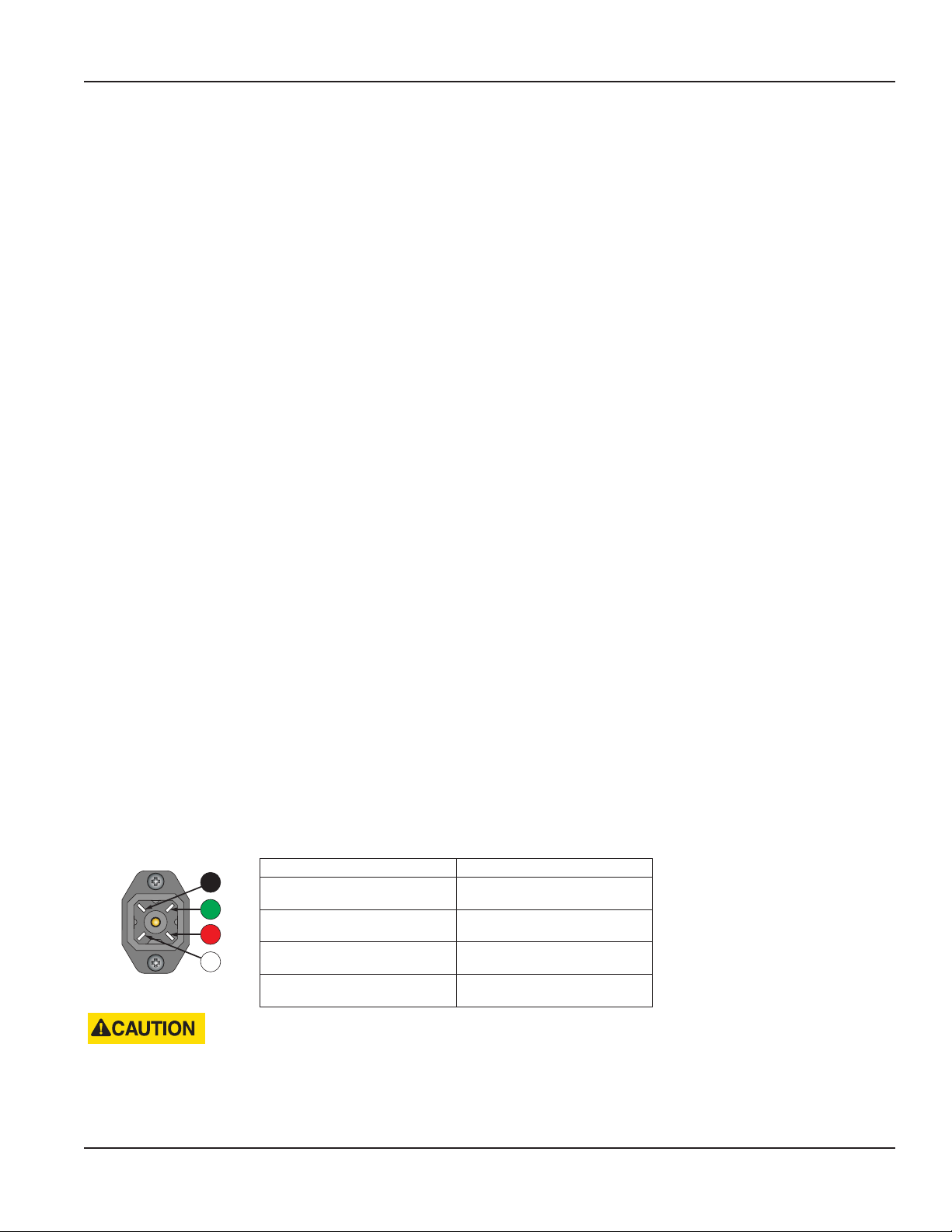
Electrical Connections
Cable may be shortened or lengthened as required for proper installation. The cable is soldered directly to the electrical
connector at the factory.
Cable replacement requires disassembly of the electrical connector.
2
3
421
Figure 1: 4-pin cable connection
3
1
4
THE FLOW TRANSMITTER IS DESIGNED TO OPERATE ONLY ONE OF ITS THREE OUTPUTS AT A TIME (0…5V DC OR
0…10V DC OR 4…20 MA). CONNECTING MULTIPLE OUTPUTS SIMULTANEOUSLY WILL RESULT IN INACCURATE OUTPUT
SIGNAL LEVELS.
DC Output Connection Loop Power Connection
No Connection (-) 4…20 mA Out
0V DC No Connection
(+) DC Power (+) 4…20 mA In
0…5 or 0…10V DC Output No Connection
Page 7 February 2023
Page 8
Transmitter
Connector
Installation
Schematics
The transmitter can be wired in various configurations to allow interface with many different types of data collection and
control instrumentation.
Schematics 1 & 2 (Figure 3) represent typical wiring for a target powered by either AC power or DC supply.
Schematics 3 & 4 (Figure 3) will be used when the flow transmitter is operated with loop-powered process indicators or data
loggers that do not have external sensor excitation available.
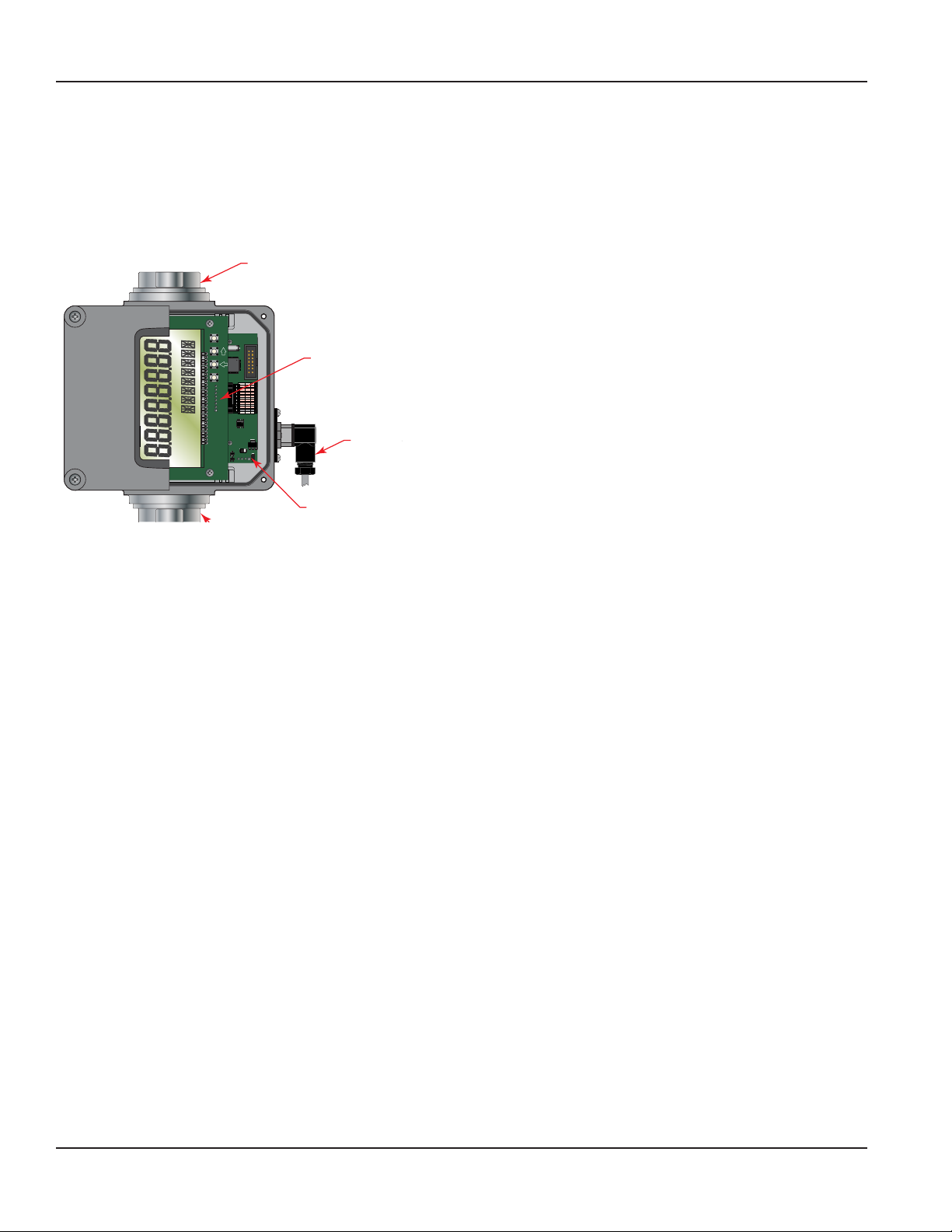
Outlet Port
Display Board
MENU ENTER
RUN PROGRAM
RELAY 1 RELAY 2
Sensor Board
Figure 2: Terminology
Page 8 February 2023
Page 9
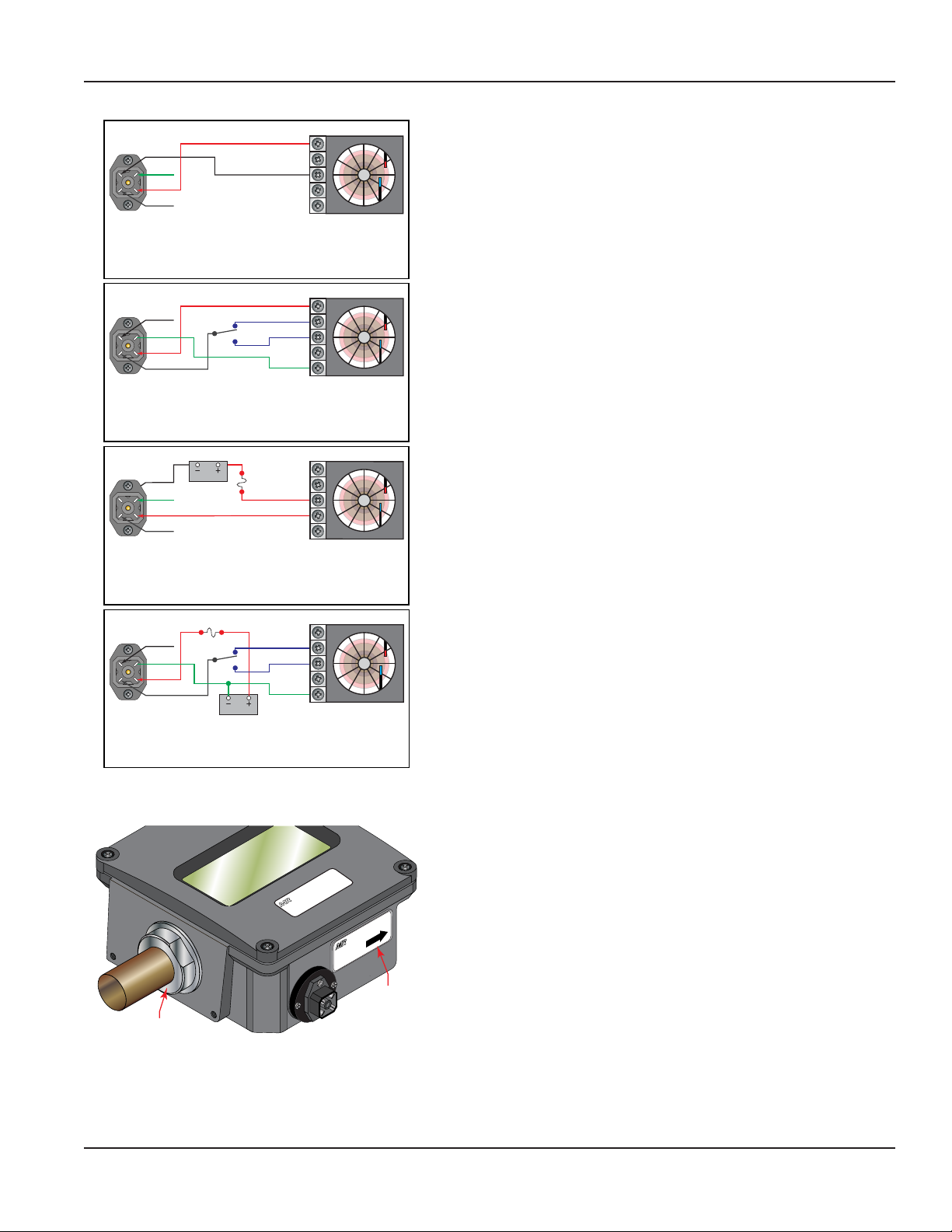
External DC
Sensor Excitation
4-20 mA Input
421
Black
Green
3
Red
White
Schematic 1: 4…20 mA connection using targets
power supply.
Example:
Chart Recorder
Installation
Sensor Excitation
0-5 VDC Input
0-10 VDC Input
Ground
421
Black
Green
3
Red
White
Schematic 2: 0…5 Vdc or 0…10 Vdc connection using
targets power supply.
421
Black
Excitation
Green
3
Voltage
Red
White
Fuse: 0.05 A Fast
4-20 mA Input (-)
4-20 mA Input (+)
Schematic 3: 4…20 mA connection using targets
external power supply.
Fuse: 0.05 A Fast
0-5 VDC Input
0-10 VDC Input
Excitation
Voltage
Ground
421
Black
Green
3
Red
White
Schematic 4: 0…5 Vdc or 0…10 Vdc connection using
targets external power supply.
Example:
Chart Recorder
Example:
Chart Recorder
Example:
Chart Recorder
Flow
Inlet Port
Figure 3: Wiring diagrams
Flo w Tra ns mi tt er
OIL
3500 PSI/ 241 BARS MAX
Figure 4: Flow direction arrow
Fl ow Tr an sm it te r
Model H600A-000-MR
S.N.: 78500
Date: 0412
Direction
FLOW
Flow
Arrow
Page 9 February 2023
Page 10
Installation
Installing the Transmitter
1. Disconnect the electrical power from the target system before making or changing any transmitter connections.
2. Use 0.05 A fast-acting fuse if non-current limited power sources are used.
3. Terminate cable shield connection at either DC ground or earth ground.
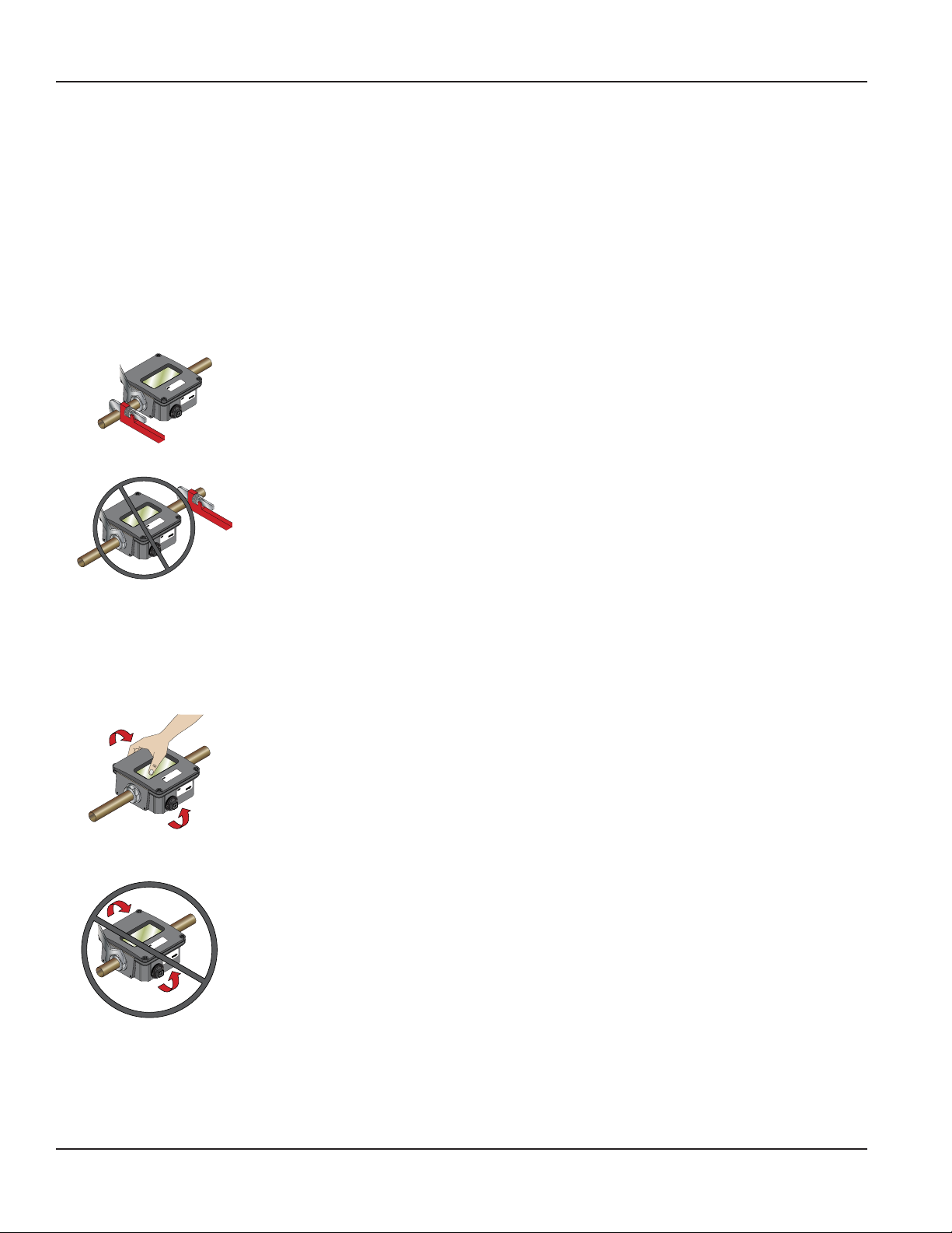
4. Mount the transmitter so uid is traveling in the direction of the ow arrow. See Figure 4.
5. Install unit in desired location. Use wrench on transmitter ats to hold the unit in place during installation. DO NOT TURN
the transmitter using the wrench. See Figure 5.
6. After installation, rotate the transmitter by hand to view the display. See Figure 6.
7. Capture the zero ow position on the meter cone using the ZERO CAPTURE procedure.
Flow Trans mi tt er
OIL
3500 PSI/241 BARS MAX
Flow Tr ans mi tt er
FLOW
Model H600A-000-MR
S.N.: 78500
Date: 0412
Place wrench on transmitter ats on the same
side plumbing is being tightened
Flow Trans mi tt er
OIL
3500 PSI/241 BARS MAX
Flow Tr ans mi tt er
FLOW
Model H600A-000-MR
S.N.: 78500
Date: 0412
Never place wrench on transmitter ats
opposite plumbing being tightened
Figure 5: Installing the meter
Flow Tran smi tt er
OIL
3500 PSI/241 BAR S MAX
Flow Tr an sm it ter
FLOW
Model H600A-000-MR
S.N.: 78500
Date: 0412
Place wrench on transmitter ats on the
same side plumbing is being tightened
Flow Tran smi tt er
OIL
3500 PSI/241 BAR S MAX
Flow Tr an sm it ter
FLOW
Model H600A-000-MR
S.N.: 78500
Date: 0412
Never place wrench on transmitter ats
opposite plumbing being tightened
Figure 6: Rotating meter
Page 10 February 2023
Page 11
Operation
OPERATION
Operating the Meter
The monitor has two modes of operation, referred to as RUN mode and PROGRAM mode as indicated on the display screen
readout. Normal operation will be in the run mode. To access the program mode, press MENU until the first programming
screen DISPLAY appears.
OTE: N PROGRAM appears on left side of display.
After programming the meter, a password may be entered to prevent unauthorized access to programming.
Buttons
During normal operation, the transmitter will show RUN on the left side of the display. In RUN mode the flow rate and total
flow will alternate being shown as the default. The meter can also be set to show only flow rate or only flow total.
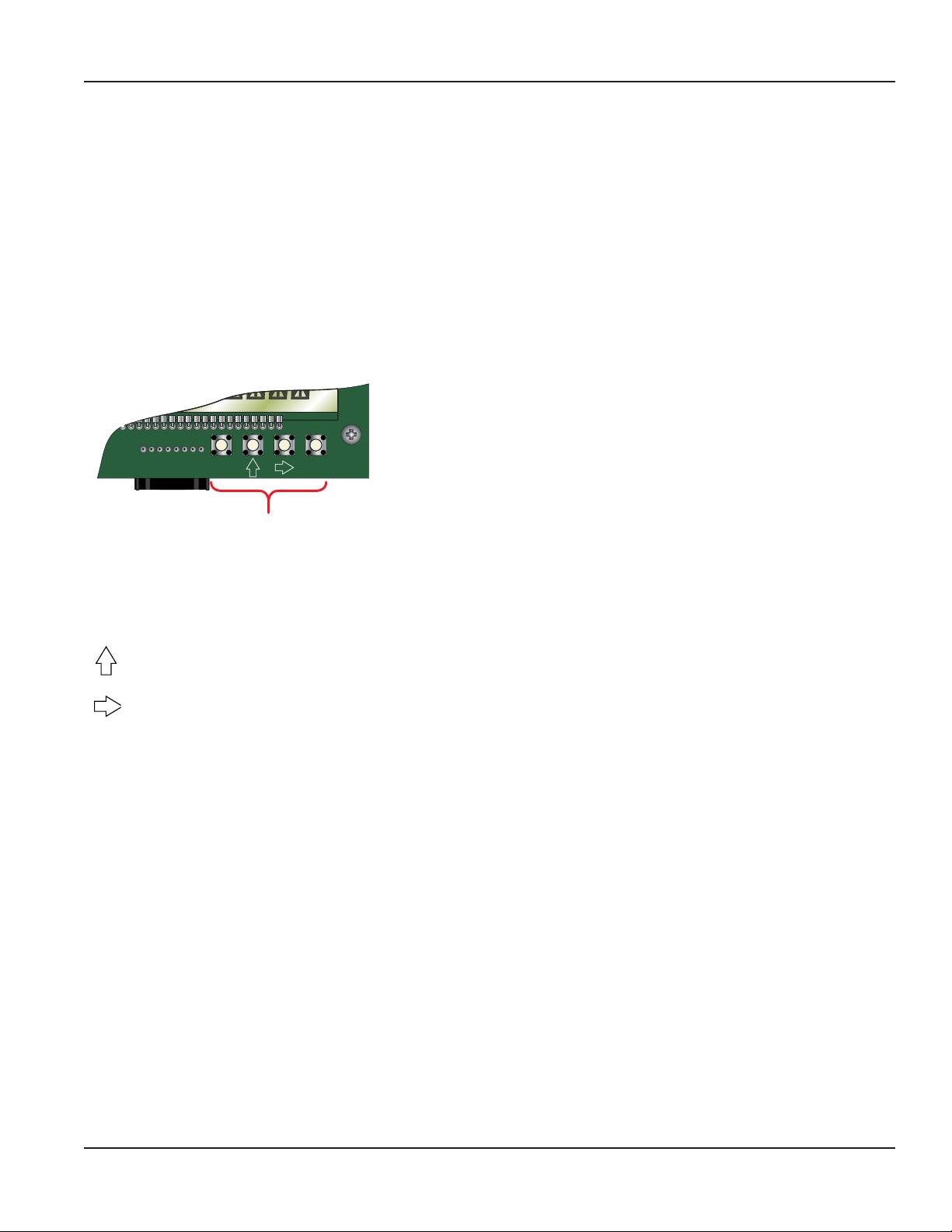
MENU ENTER
Programming
Buttons
Figure 7: Programming buttons
The four buttons have the following function in RUN mode:
MENU Selects programming mode.
UP No function.
RIGHT No function.
ENTER
The current total can be manually stored in the monitor's flash memory. Press and hold ENTER for 2
seconds. The display will respond with a flashing TOTALSVD and then will return to RUN mode.
To reset the monitor's total display, press MENU and ENTER simultaneously until TOTALRST starts to flash.
RESET TOTAL
The TOTALRST will stop flashing and the display will return to RUN mode at the conclusion of the
rest procedure.
Page 11 February 2023
Page 12
Operation
Programming Operation (PROGRAM) Mode
The programming mode lets you change the configuration and adjust the calibration of the meter. The MR flow transmitter
has two types of configuration changes accessible in program mode:
1. To view or change selections from a pre-dened list.
2. To view or change numeric entries.
During programming operation, the following four button functions are provided:
Enters and exits programming mode. Press MENU once to change to
MENU
ENTER Used to enter menus, to change configurations and to save
OTE: N If any input value exceeds the meter’s capabilities, the LIMIT indicator will begin to flash indicating an invalid entry.
programming mode. The mode indicator on the display will change
from RUN to PROGRAM.
Scrolls through the configuration choices in a bottom-to-top order. For
numeric setup, this button increments numeric values.
Use to scroll through the configuration choices in a top-to-bottom
order. For numeric setup, this button moves the active digit to the right.
programming information.
Press ENTER once to return to the entry screen to reenter the value.
Cover Removal/Reinstallation
It is necessary to remove the MR flow transmitter cover to access the programming keys. Use a Phillips screwdriver to remove
the four screws that hold the cover in place, turning them counterclockwise. When programming is completed, reinstall the
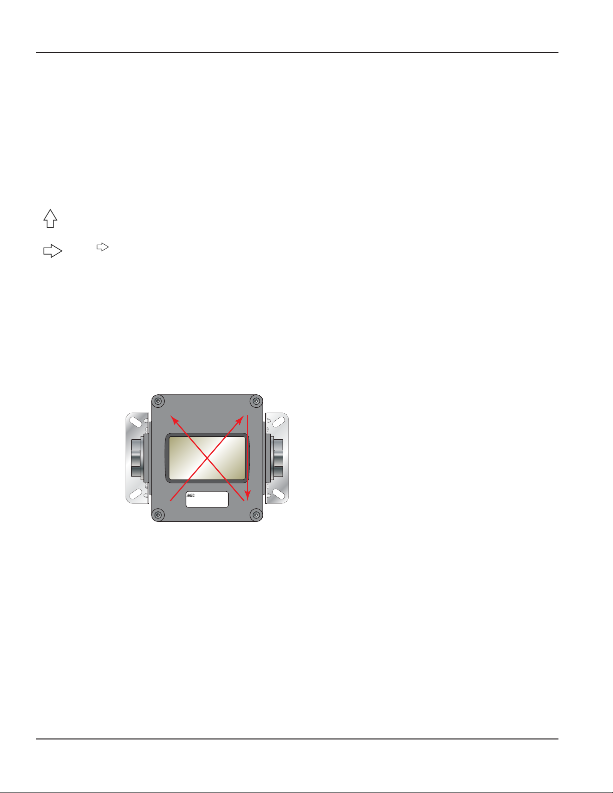
cover. To properly seat the built-in cover gasket, tighten the cover screws clockwise in a crisscross pattern as shown in Figure 8.
4
Flow Transmitter
3500 PSI/241 BARS MAX
1
Figure 8: Cover screw tightening sequence
OIL
2
3
Programming Procedures
The MR flow transmitter has been programmed at the factory according to the specifications that were provided at the time
of order. No further programming is required unless a change has occurred in the original specifications.
If programming is required, the MR flow transmitter allows two basic sets of programming procedures:
• List Item Selection
• Numeric Value Entry
Page 12 February 2023
Page 13

Operation
List Item Selection Procedure
OTE: N If you are already in PROGRAM mode and the selection to be viewed or changed is already displayed, proceed to step
3 below. If you are in PROGRAM mode and the selection to be viewed or changed is not displayed, press or
and repeat pressing until the desired selection appears. Proceed to step 3.
1. Press MENU. PROGRAM appears in the lower left-hand corner and DISPLAY appears.
2. Press or to move to the desired selection.
3. Press ENTER to view the current selection.
4. If the current selection is desired, press ENTER to confirm. The unit will automatically advance.
5. If current selection must change, press or to scroll through the available choices. Press ENTER to conrm your
selection. The unit will automatically advance.
6. To exit programming, press MENU. The display will change to RUN mode.
Numeric Value Entry Procedure
OTE: N If you are already in PROGRAM mode and the desired selection is displayed, proceed to step 3 below. If you are in
PROGRAM mode and the desired selection is not displayed, press or and repeat pressing until the desired
selection appears. Proceed to step 3.
1. Press MENU. PROGRAM appears in the lower left-hand corner and DISPLAY appears.
2. Press or to move to the desired selection. The current numeric value for this selection appears in the upper section
of the display.
3. If the current displayed value is desired, press ENTER. The left most programmable number begins to ash. Press ENTER
again to conrm and keep the current setting. The unit will automatically advance.
4. If the current selection must change, press ENTER. The left most programmable number begins to ash. Use to scroll
through the digits 0-9 and change the flashing digit to the desired value. Use to move the active digit to the right.
Continue using the and until all desired digits are selected.
5. Press ENTER to conrm your selection. The unit will automatically advance.
6. To exit programming mode, press MENU. The display will change to RUN mode.
Programming Flow Chart
See the programming flow charts in “Application Information, Liquid” on page 19 for the menu structure of the MR flow
transmitter and the available configuration selections.
Basic Programming Descriptions
Display Mode
The meter can display RATE (flow rate) or TOTAL (total accumulated flow) or alternate between BOTH rate and total. Its
displayed name is DISPLAY and is viewed or changed using the “List Item Selection Procedure” on page 13.
Rate Units of Measure
The meter allows the selection of many common rate units. Its displayed name is RATE UNT and is viewed or changed using
the “List Item Selection Procedure” on page 13.
Rate (Time) Interval
The meter allows selection of several intervals based on time. Its displayed name is RATE INT and is viewed or changed using
the “List Item Selection Procedure” on page 13.
Total Units of Measure
If the total flow is being displayed, the units for the total must first be chosen. The monitor allows the choice
of many common totalization units. Its displayed name is TOTL UNT and is viewed or changed using the
“List Item Selection Procedure” on page 13.
Page 13 February 2023
Page 14

Operation
Total Display Multiplier
The meter has the ability to accumulate the flow total in multiples of ten. For example, if the most desirable totalization
unit is 1000 gallons, the monitor can easily be set up for this requirement. Once back in RUN mode, every time the total
display increments by one digit the actual total would be an additional 1000 gallons. At 1000 total gallons the total
display would read 1, at 3000 gallons the total display would read 3. This feature allows the unit to accumulate totals
that would exceed the 8-digit display capacity. Its displayed name is TOTL EXP and is viewed or changed using the
“List Item Selection Procedure” on page 13.
Exponent Totalizer Multiplier
E-2 x 0.01 (÷100)
E-1 x 0.1 (÷100)
E0 x 1 (no multiplier)
E1 x 10
E2 x 100
E3 x 1000
E4 x 10,000
E5 x 100,000
E6 x 1,000,000
Full Flow Rate
The full flow rate is used to span the meter. Its displayed name is FULL FLOW and is viewed or changed using the
“Numeric Value Entry Procedure” on page 13.
Zero Capture
The zero position of the meter cone must be set when installing the meter. To capture the zero calibration position, press
ENTER at the ZERO CAP prompt. NO will display. Press either arrow key to change to YES, then press ENTER to capture zero.
Viscosity Units (Displayed for OIL meters only)
The Viscosity Units parameter is used in conjunction with Viscosity to perform viscosity correction for oil applications. The
meter allows the selection of the viscosity units, SUS or cSt. Its displayed name is VIS UNIT and is viewed or changed using the
“List Item Selection Procedure” on page 13.
Page 14 February 2023
Page 15

Operation
Viscosity (Displayed for OIL meters only)
Viscosity is used in conjunction with Viscosity Units to perform viscosity correction for oil applications. Enter the viscosity in
either SUS or cSt, depending on the viscosity units selected, of the oil that will be used. Its displayed name is VISCOSTY and is
viewed or changed using the “Numeric Value Entry Procedure” on page 13.
Operating Pressure Unit (Displayed for GAS meters only)
Operating Pressure Units is used in conjunction with Operating Pressure in gas applications to compensate for the actual
pressure being measured at the meter. The meter allows the selection of the operating pressure units, Bar or PSI. Its displayed
name is PRESUNIT and viewed or changed using the “List Item Selection Procedure” on page 13.
Operating Pressure (Displayed for GAS meters only)
Operating Pressure is used in conjunction with Operating Pressure Units in gas applications to compensate for the
actual pressure being measured at the meter. Enter the operating pressure in either Bar or PSI units, depending
on the Operating Pressure Units selected. Its displayed name is OP PRES and is viewed or changed using the
“Numeric Value Entry Procedure” on page 13.
Operating Temperature Unit (Displayed for GAS meters only)
Operating Temperature Units is used in conjunction with Operating Temperature in gas applications to compensate for the
actual temperature of the gas being measured at the meter. The meter allows the selection of the operating temperature
units, °F or °C. Its displayed name is TMP UNIT and is viewed or changed using the “List Item Selection Procedure” on page 13.
Operating Temperature (Displayed for GAS meters only)
Operating Temperature is used in conjunction with Operating Temperature Units in gas applications to compensate
for the actual temperature of the gas being measured at the meter. Enter the operating temperature in either °F or °C,
depending on the Operating Temperature Units selected. Its displayed name is OP TEMP and is viewed or changed using the
“Numeric Value Entry Procedure” on page 13.
Specific Gravity Correction Factor
Specific Gravity is used to compensate for the specific gravity of the liquid or gas being measured with the meter. Its displayed
name is SP GRAV and is viewed or changed using the “Numeric Value Entry Procedure” on page 13.
Damping
The Damping factor is increased to enhance the stability of the flow readings. Damping values are decreased to allow the flow
meter to react faster to changing values of flow. This parameter can range from 0 to 99; factory default is 0. Its displayed name
is DAMPING and is viewed or changed using the “Numeric Value Entry Procedure” on page 13.
Output Mode
The MR flow transmitter offers three analog output modes:
• 4…20 mA Output Signal
• 0…5 Volts DC Output Signal
• 0…10 Volts DC Output Signal
The output mode selected is determined by the type of peripheral device being connected to the MR flow transmitter.
The displayed name is OUT MODE and is viewed or changed using the “List Item Selection Procedure” on page 13.
OTE: N Setup prompts and descriptors for configuring and calibrating the analog output will correspond to the output
mode selected.
Password
Password protection prevents unauthorized users from changing programming information. Initially the password is set to all
zeros. Its displayed name is PASSWORD and is viewed or changed using the “Numeric Value Entry Procedure” on page 13.
Restore Defaults
This feature allows you to restore factory calibration data. Its displayed name is RES DFLT. To restore factory calibration data,
select YES, then press ENTER.
Page 15 February 2023
Page 16

Operation
Advanced Programming Descriptions
Advanced programming allows the user access to re-configure the analog output. Calibration of the analog output is preset
at the factory, but can be changed to customize calibration for your installation.
To access the Advanced Programming Options, press and hold MENU for approximately
3 seconds until DISPLAY is viewed on the display panel. The programming menus will begin with display mode DISPLAY and
continue as described above through output mode
OUT MODE.
After output mode has been entered, Advanced Programming starts with the following:
Calibration of Analog Output
This selection allows access to the calibration and testing of the analog output signal.
To test or change the analog output calibration, it is first necessary to change the default setting for CAL OUT? from NO to YES.
OTE: N Setup prompts and descriptors for configuring and calibrating the analog output will correspond to the output
mode selected. Refer to the Flow Chart.
1. At the CAL OUT? prompt press ENTER. NO will display.
2. To change to YES, press either arrow key.
3. The analog output will go to its minimum output level. A numeric value between 0-4000 will display. This is an internal
number used to drive the analog output.
4. To increase the analog output signal level, press . To decrease the analog output signal level, press .
5. Press ENTER to store the setting.
6. The analog output will go to its maximum output level. A numeric value between 0-4000 will display. This is an internal
number used to drive the analog output.
7. To increase the analog output signal level, press . To decrease the analog output signal level, press .
8. Press ENTER to store the setting.
9. The unit will advance to the analog output test mode. The analog output will go to its minimum output level. A numeric
value of 0 will display. For test purposes, the analog output signal can be run up or down in increments of 1 milliamp or 1
volt, depending on the OUT MODE selected.
10. To increase the analog output signal level, press . To decrease the analog output signal level, press .
11. Press ENTER to exit the analog calibration mode.
12. The unit automatically advances to the PASSWORD feature.
Password
Password protection prevents unauthorized users from changing programming information. Initially the password is set to all
zeros. Its displayed name is PASSWORD and is viewed or changed using the “Numeric Value Entry Procedure” on page 13.
Restore Defaults
This feature allows you to restore factory calibration data. Its displayed name is RES DFLT. To restore factory calibration data,
select YES, then press ENTER.
Page 16 February 2023
Page 17
Maintenance
MAINTENANCE
BEFORE ATTEMPTING TO REMOVE THE TRANSMITTER FROM THE LINE, CHECK THE SYSTEM TO CONFIRM THAT LINE
PRESSURE HAS BEEN REDUCED TO ZERO PSI. FAILURE TO FOLLOW THESE INSTRUCTIONS COULD RESULT IN SERIOUS
PERSONAL INJURY OR DEATH AND/OR DAMAGE TO THE EQUIPMENT.
DISCONNECT ELECTRICAL POWER BEFORE REMOVING METER COVER. FAILURE TO FOLLOW THESE INSTRUCTIONS
COULD RESULT IN SERIOUS PERSONAL INJURY OR DEATH AND/OR DAMAGE TO THE EQUIPMENT.
Cartridge Cleaning
1. Disconnect the transmitter cable.
2. Remove the meter from the line. Remove excess piping from the transmitter.
See Figure 4 and Figure 5.
OTE: N It is not necessary to remove the aluminum housing from the transmitter to remove it from the line.
3. Thoroughly wipe o the entire transmitter surface using mild detergent or
isopropyl alcohol.
DO NOT USE AROMATIC HYDROCARBONS, HALOGENATED HYDROCARBONS, KETONES OR ESTER BASED FLUIDS ON
POLYCARBONATE LENS. FAILURE TO FOLLOW THESE INSTRUCTIONS COULD RESULT IN DAMAGE TO THE TRANSMITTER.
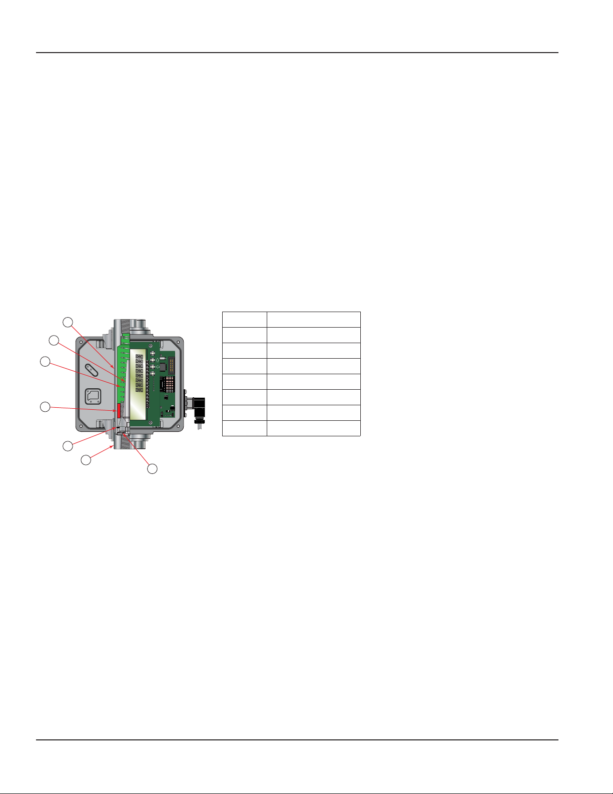
4. Remove the inlet port cap, wave spring, retaining ring, and cone assembly from the transmitter body (Figure 9).
5. Gently push the body towards the outlet port.
6. The piston, inner magnet and transmitter spring are secured within the transmitter body with a retaining ring. Remove the
retaining ring with a small screwdriver, then the internal components can be removed from the body (Figure 9).
OTE: N If internal parts do not slide freely from cartridge, use a wooden dowel inserted into the outlet port of the meter to
push parts out.
7. Place all parts on a clean work surface. Clean and inspect all parts. Replace any that appear worn or damaged. Check inlet
port O-ring for damage and replace if required.
FIELD REPLACEMENT OF THE SPRING, METERING CONE AND/OR PISTON/MAGNET ASSEMBLY MAY RESULT IN CHANGES
TO THE CALIBRATION OF THE FLOW METER.
8. Reassemble the transmitter by inserting the transmitter spring into the body, followed by the piston/inner magnet
assembly. A slight compression of the piston against the spring is required during installation of the retaining ring.
9. Gently push body assembly into the outlet end of the transmitter enclosure. The at surface of the body output port
should be ush with the transmitter enclosure opening.
10. With the transmitter positioned vertically on a at surface, inlet port facing up, install the transmitter cone assembly and
wave spring into the body and secure with the inlet port end cap.
11. Reinstall transmitter to the line. Reconnect electrical power.
Page 17 February 2023
Page 18
Troubleshooting
Inspection
1. Frequent inspection should be made. The environment and frequency of use should determine a schedule for
maintenance checks. It is recommended that it should be at least once a year.
2. Perform visual, electrical, and mechanical checks on all components on a regular basis.
3. Visually check for undue heating evidence such as discoloration of wires or other components, damaged or worn parts, or
leakage evidence such as water or corrosion in the interior.
4. Make sure all electrical connections are clean and tight and that the device is wired properly.
TROUBLESHOOTING
No LCD Display
• For 4…20 mA operation, check for current flow in the loop.
• Check polarity of the current loop connections for proper orientation.
• For 0…5V or 0…10V operation, check for proper voltage being supplied to the unit.
• Check polarity of the supply voltage.
1
2
Number Name
1 Body
2 Cone Assembly
3
MENU ENTER
3 Meter Spring
4 Piston Assembly
5 Retaining Spring
4
RUN PROGRAM
RELAY 1 RELAY 2
6 Cap
7 Wave Spring
5
6
Figure 9: Cartridge components
7
No Rate or Total Displayed
• Check flow meter body and internal components for debris. Piston should move inside the tube freely.
• Check setup programming of flow meter.
Unstable Flow Reading
• This usually indicated pulsing or oscillation in the actual flow. Increase the DAMPING parameter to increase the filtering in
order to provide a more stable display reading.
Page 18 February 2023
Page 19
Application Information, Liquid
APPLICATION INFORMATION, LIQUID
Viscosity Eect (SUS/cSt)
The design uses a precision machined, sharp- edged orifice and biasing calibration spring that assures operating stability and
accuracy over the wide viscosity range common to many fluids. Generally, high flow models of each meter size provide good
accuracy over a viscosity range of 40…500 SUS (4.2…109 cSt).
Density Eect (specic gravity)
Any fluid density change from stated standards has a proportional effect on meter accuracy. Corrections for more or less
dense fluids can be made to standard scales using the following correction factor:
10.
Specic Gravity
0 876.
Specic Gravity
For water/water-based meters
For petroleum-based meters
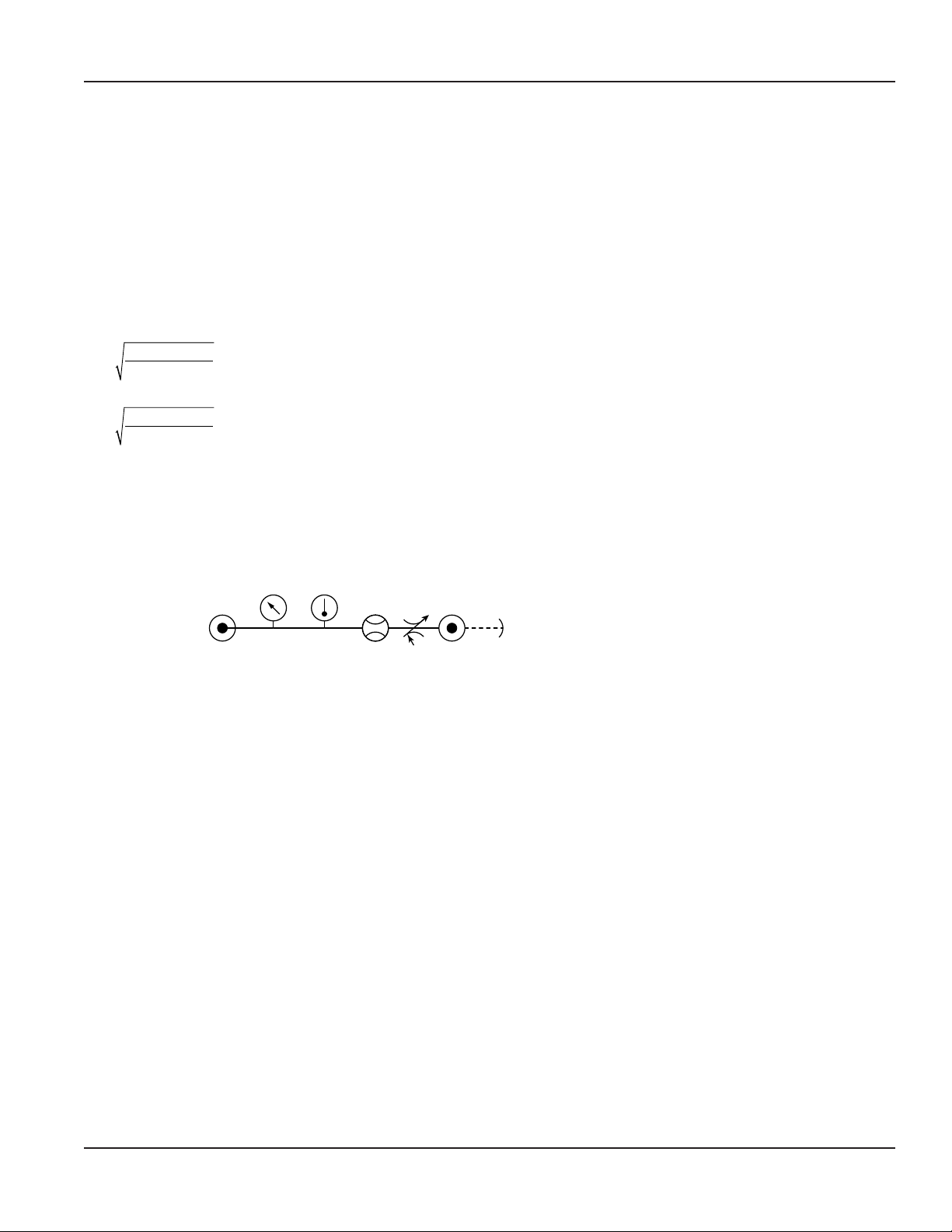
Application Information Pneumatic
OTE: N Pressure and temperature readings must be taken at the flow meter inlet to ensure accurate correction factors.
The pneumatic flow meter is calibrated for air in standard cubic feet per minute (scfm) at 1.0 s.g. (70° F @ 100 psi), and liter per
second (lps) at 1.0 s.g. (21° C @ 6.9 bar).
Pressure
Gauge
Pressure
Source
Temp
Figure 10: System schematic
Air Bleed O
to Equipment
Flow
Meter
Adjustable
Valve
Page 19 February 2023
Page 20

()
13
530
293
fSpGr
3
= ..
Application Information, Liquid
DETERMINE FLOW RATES USING DIFFERENT PRESSURES & TEMPERATURES
Where f1 = Conversion Factor for Inlet Pressure
scfm actual
()
scfm indicated
=
fxfxf
2
f2 = Conversion Factor for Inlet Pressure
f3 = Conversion Factor for Inlet Pressure
Table 1–Temperature Correction Factor (f1) Operating Pressure
psig 25 50 75 100 125 150 175 200 225 250
BAR 1.7 3.5 5.2 6.9 8.6 10.4 12.1 13.8 15.5 17.2
kPa 172 345 517 689 862 1034 1207 1379 1551 1724
f
1
1.700 1.331 1.131 1.00 0.902 0.835 0.778 0.731 0.692 0.658
790 857
7 914
f
114 7
1
14 7=+..
psig
f
1
.
1 014=+
.
BAR
f
1
.
101 357=+
.
kPa
Table 2–Temperature Correction Factor (f2)
°F 10 30 50 70 90 110 130 150 170 190
°C –12.2 –1.1 9.9 21.0 32.1 43 54 65 76 88
f
2
0.942 0.962 0.981 1.00 1.018 1.037 1.055 1.072 1.090 1.107
C
273
F
+°
460
f
=
2
f
2
+°
=
Table 3–Specific Gravity Correction Factor (f3)
OTE: N Table 2 is included to show the correction algorithms included in the program to perform pressure, temperature, and
specific gravity corrections. When configuring the MR Model, enter the actual operating pressure, temperature, and
specific gravity values, not the correction factors.
Page 20 February 2023
Page 21

Correction Factor
Application Information, Liquid
LIQUIDS
Fluid
Acetic Acid (Air
Free)
Specific
Gravity
Oil Water
Aluminum
Brass
T16 SST
T303 SST
Viton®
EPR
Nylon
Polycarbonate
1.06 0.909 0.971 C N R R R R C N R
Acetone 0.79 1.053 1.125 R R R R N R N R R
Alcohol Butyl
(Butanol)
Alcohol Ethyl
(Ethanol)
0.83 1.027 1.098 C C R R C R R R R
0.83 1.027 1.098 C C R R C R R N R
Ammonia 0.89 0.992 1.060 R C R R N R N C R
Benzine 0.69 1.127 1.204 C R R C R N N R R
Carbon Disulphide 1.26 0.834 0.891 R N R R R N N R R
Castor Oil 0.97 0.950 1.015 C R R C R N C C R
Cotton Seed Oil 0.93 0.970 1.037 C R R R R N R R R
Ethylene Glycol
50/50
1.12 0.884 0.945 R R R R R R R C R
Freon II 1.46 0.774 0.828 R R R R R N R R R
Gasoline 0.70 1.119 1.195 R R R R R N C R R
Glycerin 1.26 0.834 0.891 R R R R R R R C R
Kerosene 0.82 1.033 1.104 R R R R R N R R R
Liquid Propane
(LPG)
0.51 1.310 1.400 R R R R R N N R R
Mineral Oil 0.92 0.976 1.042 R N R R R N R R R
Naphtha 0.76 1.074 1.147 R N R R R N C R R
Perchloroethylene 1.62 0.735 0.786 C N R R R N N N R
Petroleum Oil 0.876 1.000 1.068 R R R R R N R R R
Phosphate Ester 1.18 0.862 0.921 R R R R N R N R R
Phosphate Ester
Base
Phosphoric Acid
(Air Free)
1.26 0.833 0.891 R R R R N R N R R
1.78 0.701 0.749 N N R N R N R N R
Sea Water 1.03 0.922 0.985 N N C C N R R R R
Synthetic
Petroleum Base
1.00 0.936 1.000 R C R R R N R R R
Water 1.00 0.936 1.000 N R R R N R R R R
Water Glycol 50/50 1.07 0.905 0.967 R R R R R N R R R
Water-in-oil 0.93 0.970 1.037 R R R R N R R R R
R–Recommended
N–Not Recommended
C–Consult Factory
Pyrex®
Page 21 February 2023
Page 22

Application Information, Liquid
LIQUIDS
Fluid
Specific
Gravity
Correction
Factor
Aluminum
Brass
T16 SST
T303 SST
Viton®
EPR
Nylon
Polycarbonate
Air 1.0 1.000 R R R R R R R R R
Argon (A) 1.38 1.175 R R R R R R R R R
Carbon Dioxide
(CO2)
1.53 1.237 R R R R R R R R R
Freon 11 (CCI3F) 4.92 2.218 R R R R R R R R R
Freon 12 (CCI2F) 4.26 2.060 R R R R R R R R R
Helium (HE) 0.14 0.374 R R R R R R R R R
Hydrogen (H2) 0.07 0.265 R R R R R R R R R
Natural Gas 0.60 0.775 C C R C R N C R R
Nitrogen (N2) 0.97 0.985 C C R R R R C R R
Oxygen (O2) 1.10 1.049 R R R R R R R R R
Propane C3H8) 1.57 1.253 R R R R R N N R R
R–Recommended
N–Not Recommended
C–Consult Factory
Pyrex®
Page 22 February 2023
Page 23
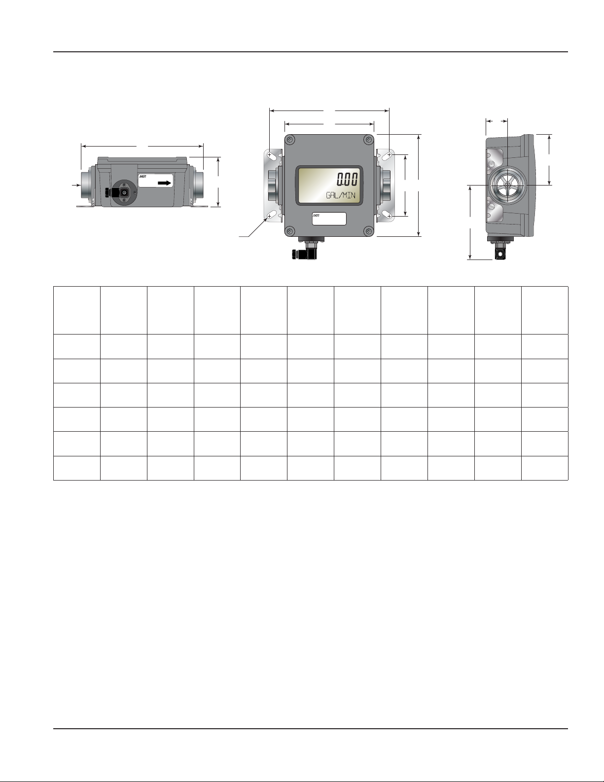
DIMENSIONS
B
A
421
3
Flo w Tra ns mi tt er
FLOW
Dimensions
D
C
I
K
RUN
Flow Transmitter
3500 PSI/241 BARS MAX
OIL
Figure 11: Dimensions
F E
J
G
H
A
Nominal
Port Size
1/4
(SAE 6)
1/2
(SAE 10)
3/4
(SAE 12)
1
(SAE 16)
1-1/4
(SAE 20)
1-1/2
(SAE 24)
B
Length
in.
(mm)
C
Length
in.
(mm)
D
Length
in.
(mm)
E
Width
in.
(mm)
6.60 (168) 5.27 (134) 6.41 (163) 6.00 (152)
6.60 (168) 5.27 (134) 6.41 (163) 6.00 (152)
7.20 (183) 5.27 (134) 7.04 (179) 6.00 (152)
7.20 (183) 5.27 (134) 7.04 (179) 6.00 (152)
12.20
(310)
12.20
(310)
10.68
(271)
10.68
(271)
11.65
(296)
11.65
(296)
7.63 (194) 4.84 (123)
7.63 (194) 4.84 (123)
F
Width
in.
(mm)
3.23
(82)
3.23
(82)
3.60
(91)
3.60
(91)
G
Width
in.
(mm)
3.00
(76)
3.00
(76)
3.00
(76)
3.00
(76)
3.82
(97)
3.82
(97)
H
Width
in.
(mm)
4.20 (107)
4.20 (107)
4.20 (107)
4.20 (107)
I
Depth
in.
(mm)
2.94
(75)
2.94
(75)
2.94
(75)
2.94
(75)
5.02 (128) 4.50 (114)
5.02 (128) 4.50 (114)
J
Offset
in.
(mm)
1.51
(38)
1.51
(38)
1.27
(32)
1.27
(32)
2.20
(56)
2.20
(56)
K
Hole Dia.
in.
(mm)
0.31
(8)
0.31
(8)
0.31
(8)
0.31
(8)
0.31
(8)
0.31
(8)
Page 23 February 2023
Page 24

Specications
SPECIFICATIONS
General
Accuracy ± 2% of full scale
Repeatability ± 1%
Threads SAE J1926/1, NPTF ANSI B2.2, BSPP IS01179
Temperature Range –20…240° F (–29…116° C)
Pressure Rating Aluminum/Brass Operating
Liquids: 3500 psi/241 bar maximum (3:1 safety factor)
Gases: 1000 psi/69 bar maximum (10:1 safety factor)
Stainless Steel Operating
Liquids (1/4…1/2"): 6000 psi/414 bar maximum (3:1 safety factor)
Liquids (3/4…1-1/2"): 5000 psi/345 bar maximum (3:1 safety factor)
Gases: 1500 psi/103 bar maximum (10:1 safety factor)
Page 24 February 2023
Page 25

Materials
All Meters Common Parts 2024 – T351 Anodized aluminum body, piston and cone
C360 Brass body, piston and cone
T303 Stainless body, 2024 – T351 Anodized aluminum piston and con (Oil, PE WBF, &
Air meters)
T303 Stainless body, C360 Brass piston and con (Water meters)
T316 Stainless body, piston and cone
Petroleum (Oil) Common Parts Spider Plate
Retaining Ring
Spring
Retaining Spring
Fasteners
Internal Magnet
Pressure Seals
Enclosure Seal
Lens
Phosphate Ester (PE) Common Parts Spider Plate
Retaining Ring
Spring
Retaining Spring
Fasteners
Internal Magnet
Pressure Seals
Enclosure Seal
Lens
Water-Based (WBF), Water, Air
Common Parts
API Oil/Air/Caustic/Corrosive
Liquids and
Gases Common Parts
Spider Plate
Retaining Ring
Spring
Retaining Spring
Fasteners
Internal Magnet
Pressure Seals
Enclosure Seal
Lens
Spider Plate
Retaining Ring
Spring
Retaining Spring
Fasteners
Internal Magnet
Pressure Seals
Enclosure Seal
Lens
T316 SS
SAE 1070/1090 Carbon Steel
302 SS
SAE 1070/1090 Carbon Steel
T303 SS
Teflon® Coated Alnico 8
Viton®
Silicon gasket
Polycarbonate
T316 SS
SAE 1070/1090 Carbon Steel
302 SS
SAE 1070/1090 Carbon Steel
T303 SS
Teflon Coated Alnico 8
EPR
Silicon gasket
Polycarbonate
T316 SS
T316 SS
T302 SS
T316 SS
T303 SS
Teflon Coated Alnico 8
Viton
Silicone gasket
Polycarbonate
T316 SS
T316 SS
T316 SS
T316 SS
T316 SS
Teflon Coated Alnico 8
Viton
Silicone gasket
Polycarbonate
Specications
Page 25 February 2023
Page 26

Specications
High Cycle Applications: Pressure
Fatigue Rating
Per NFPA/T2.6.1 R1 - 1991, C/90, the method of verifying rated fatigue pressure (or
establishing the rated burst pressure, or both) of the pressure containing envelope
conforms to NFPA/T2.6.1 R1, Fluid power systems and products – Method for
verifying the fatigue and establishing the burst pressure ratings of the pressure
containing envelope of a metal fluid power component.
Meter Size Aluminum Brass Stainless Steel
RFP* Cycles RFP* Cycles RFP* Cycles
1/4 2000 1×10
1/2 2000 1×10
3/4 1500 1×10
1 1500 1×10
1-1/4 1000 1×10
1500 70×10
1-1/2 1000 1×10
1500 70×10
6
** 3000 1×10
6
** 3000 1×10
6
** 3000 1×10
6
** 3000 1×10
6
** 3000 1×10
3
** 3000 1×10
6
** 3000 1×10
3
** 3000 1×10
*RFP = Rated Fatigue Pressure
**Consult Factory
6
6
6
6
6
6
6
6
Page 26 February 2023
Page 27
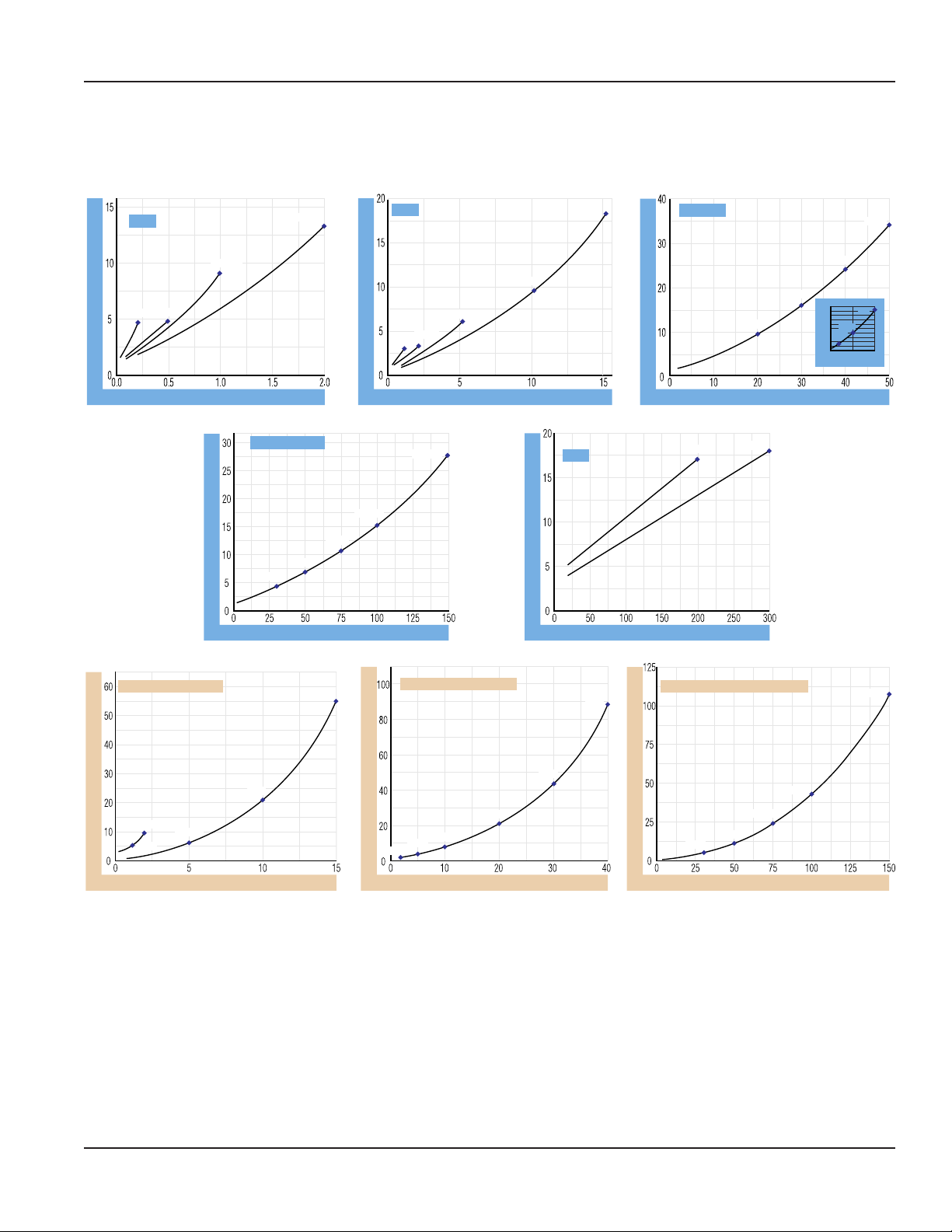
FLOW VS PRESSURE DROP
Petroleum Fluids
Flow vs Pressure Drop
PRESSURE DROP, PSI
1/4"
.02-.20
.05-.50
.10-1.0
FLOW, GPM
PRESSURE DROP, PSI
.20-2.0
1-1/4"/1-1/2"
5-50
3-30
FLOW, GPM
10-75
10-100
PRESSURE DROP, PSI
1/2"
0.1-1.0
0.2-2.0
10-150
0.5-5.0
FLOW, GPM
1-10
PRESSURE DROP, PSI
3.0"
1-15
PRESSURE DROP, PSI
FLOW, GPM
3/4"/ 1"
10-200
2-20
FLOW, GPM
20-300
3-30
4-40
10
0.5-5.0
5
0.2-2.0
0
0 10
5-50
1-10
1/2" Reverse Flow
0.2-2.0
PRESSURE DROP, PSI
0.1-1.0
0.5-5.0
FLOW, GPM
1-10
1-15
3/4"/1" Reverse Flow
0.5-5.0
1-10
PRESSURE DROP, PSI
0.2-2.0
4-40
3-30
2-20
FLOW, GPM
1-1/4"/1-1/2" Reverse Flow
PRESSURE DROP, PSI
3-30
5-50
FLOW, GPM
10-150
10-100
10-75
The pressure drop curves are valid for fluids with density and viscosity similar to factory test fluids. Fluids, especially with
higher viscosity than theses test fluids, will yield a higher pressure drop through the flow meter and piping system per a given
flow volume.
A system must have adequate fluidic horsepower available to move the system fluid at a prescribed rate at a pressure
adequate to overcome all pressure reducing devices, including the flow meter.
Page 27 February 2023
Page 28
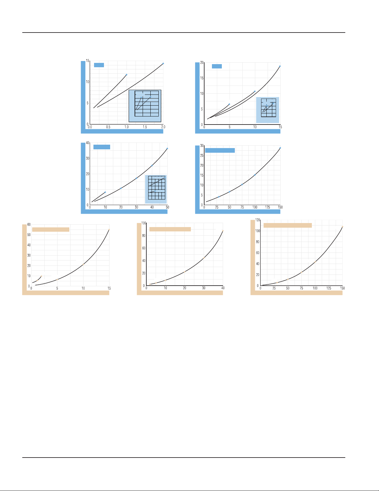
PRESSURE DROP, PSI
Flow vs Pressure Drop
Phosphate Ester
1/2" Reverse Flow
PRESSURE DROP, PSI
PRESSURE DROP, PSI
1/4"
3/4"/ 1"
1-10
1-15
0.10-1.0
FLOW, GPM
2-20
FLOW, GPM
3-30
0.20-2.0
.02-.20
6
.05-.50
4
2
0
0.50.0
1/2"
1-10
0.5-5.0
PRESSURE DROP, PSI
4
0.1-1.0
2
0
0 1 2 2.5
1-15
0.2-2.0
FLOW, GPM
4-40
6
4
2
0
0 1 2 3 54
0.5-5.0
0.2-2.0
5-50
1-1/4" / 1-1/2"
PRESSURE DROP, PSI
10-100
10-75
5-50
3-30
10-150
FLOW, GPM
3/4"/1" Reverse Flow
4-40
1-1/4"/1-1/2" Reverse Flow
10-150
0.2-2.0
0.1-1.0
0.5-5.0
FLOW, GPM
1-10
PRESSURE DROP, PSI
0.2-2.0
0.5-5.0
1-10
2-20
FLOW, GPM
3-30
PRESSURE DROP, PSI
3-30
10-100
10-75
5-50
FLOW, GPM
Page 28 February 2023
Page 29
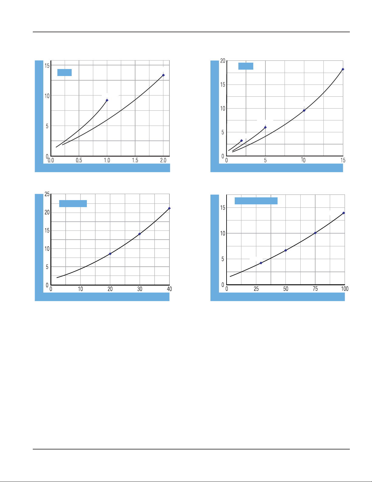
API Oil
Flow vs Pressure Drop
PRESSURE DROP, PSI
1/4"
3/4" / 1"
.10-1.0
FLOW, GPM
3-30
.20-2.0
4-40
PRESSURE DROP, PSI
1/2"
0.5-5.0
0.2-2.0
FLOW, GPM
1-1/4"/ 1-1/2"
1-15
1-10
10-100
10-75
PRESSURE DROP, PSI
2-20
FLOW, GPM
5-50
3-30
PRESSURE DROP, PSI
FLOW, GPM
Page 29 February 2023
Page 30
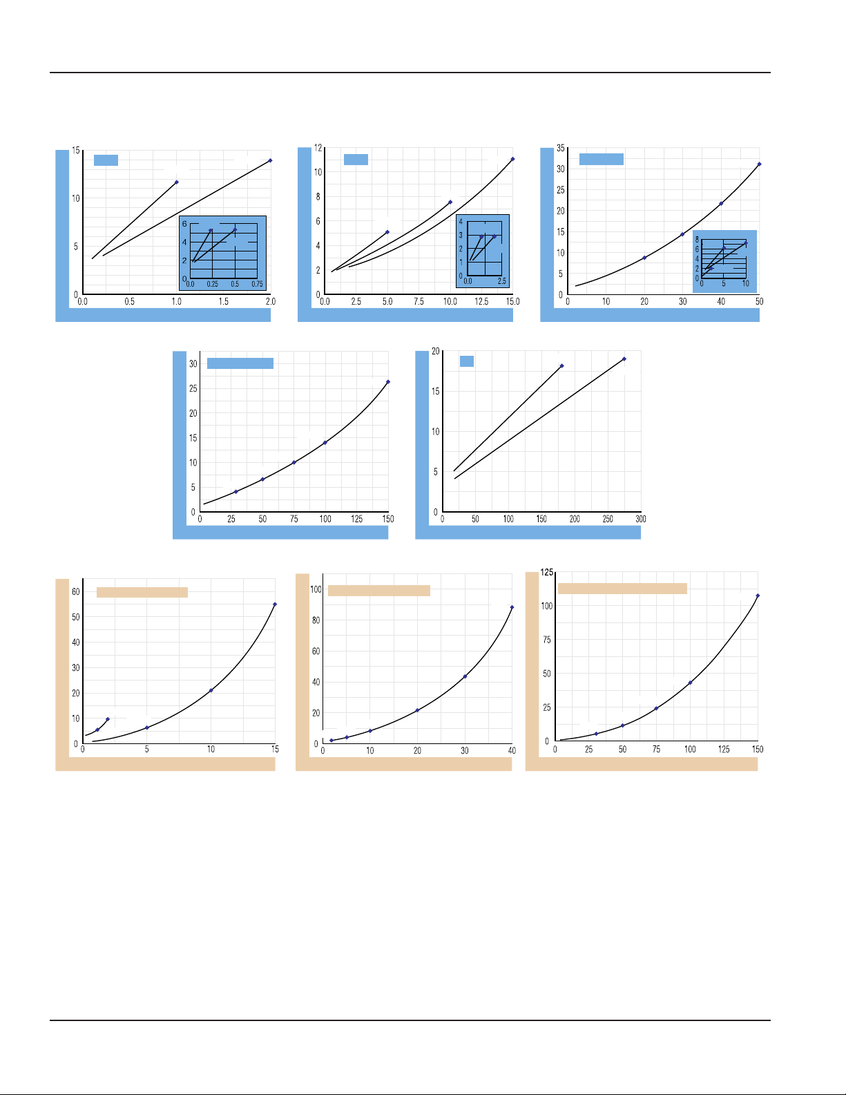
Flow vs Pressure Drop
Water-Based Fluids
PRESSURE DROP, PSI
1/4"
.10 -1.0
FLOW, GPM
PRESSURE DROP, PSI
.20-2.0
0.2-2.0
.05-.50
1-1/4"/ 1-1/2"
3-30
10-75
5-50
FLOW, GPM
PRESSURE DROP, PSI
10-100
1/2"
10-150
0.5-5.0
FLOW, GPM
PRESSURE DROP, PSI
1-10
3"
0.1-1.0
1-15
0.2-2.0
PRESSURE DROP, PSI
20-180
FLOW, GPM
3/4" / 1"
2-20
FLOW, GPM
20-275
3-30
4-40
0.5-5.0
5-50
1-10
0.2-2.0
1/2" Reverse Flow
0.2-2.0
PRESSURE DROP, PSI
0.1-1.0
0.5-5.0
1-10
FLOW, GPM
1-15
3/4"/1" Reverse Flow
PRESSURE DROP, PSI
1-10
0.5-5.0
0.2-2.0
2-20
FLOW, GPM
3-30
4-40
1-1/4"/1-1/2" Reverse Flow
PRESSURE DROP, PSI
3-30
5-50
10-150
10-100
10-75
FLOW, GPM
Page 30 February 2023
Page 31
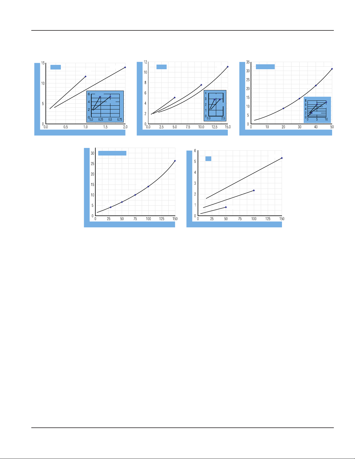
Water
Flow vs Pressure Drop
PRESSURE DROP, PSI
1/4"
.10 -1.0
FLOW, GPM
PRESSURE DROP, PSI
.20-2.0
0.2-2.0
.05-.50
1-1/4"/ 1-1/2"
3-30
10-75
5-50
FLOW, GPM
PRESSURE DROP, PSI
10-100
1/2"
10-150
0.5-5.0
FLOW, GPM
PRESSURE DROP, PSI
1-10
3"
0.1-1.0
1-15
0.2-2.0
PRESSURE DROP, PSI
5-50
FLOW, GPM
10-100
3/4" / 1"
2-20
FLOW, GPM
15-150
3-30
4-40
0.5-5.0
5-50
1-10
0.2-2.0
Page 31 February 2023
Page 32
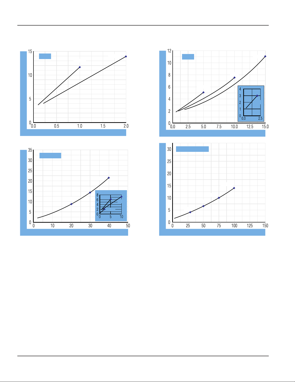
Flow vs Pressure Drop
Caustic and Corrosive Liquids
PRESSURE DROP, PSI
PRESSURE DROP, PSI
1/4"
3/4" / 1"
.10 -1.0
FLOW, GPM
3-30
2-20
4-40
0.5-5.0
.20-2.0
0.1-2.0
1-10
PRESSURE DROP, PSI
1-1/4"/ 1-1/2"
PRESSURE DROP, PSI
1/2"
3-30
1-15
1-10
0.5-5.0
0.2-2.0
FLOW, GPM
10-100
10-75
5-50
FLOW, GPM
Page 32 February 2023
FLOW, GPM
Page 33
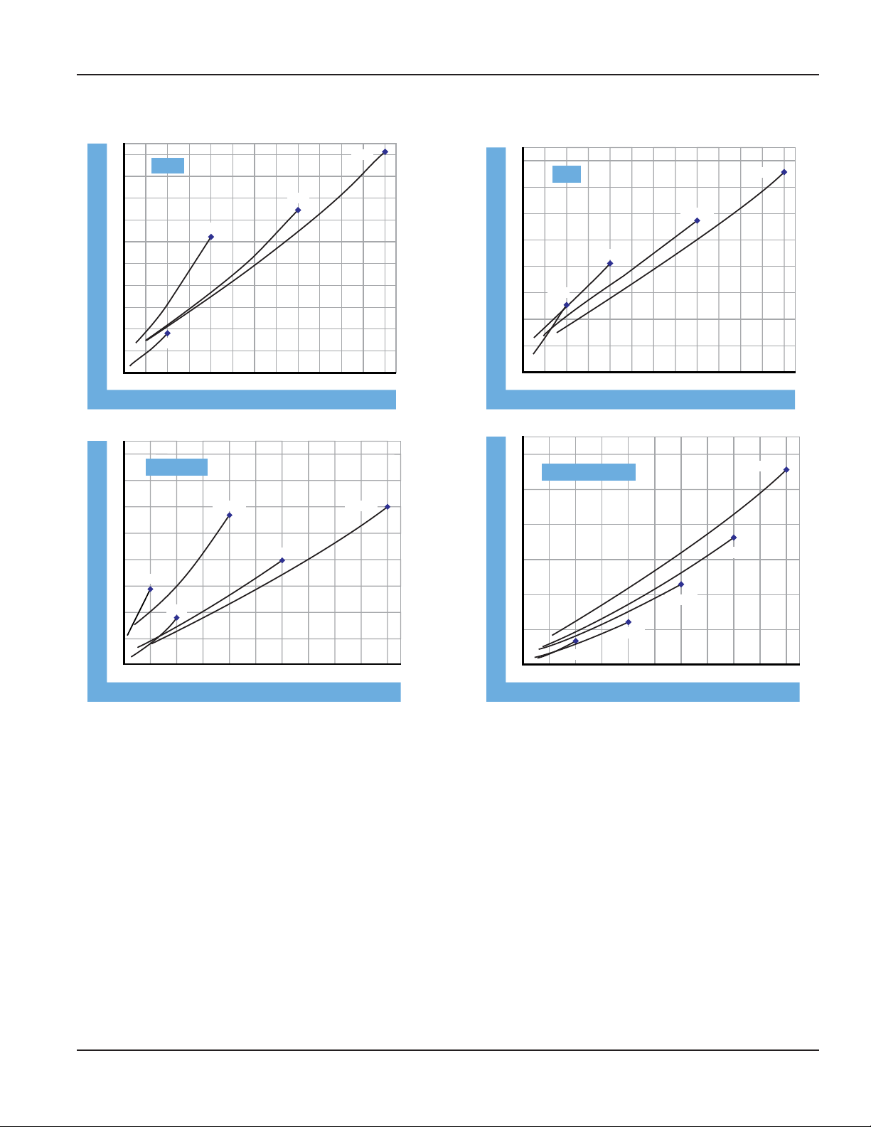
Air/Compressed Gases
Flow vs Pressure Drop
25
20
1/4"
2-20
1-10
15
10
5
PRESSURE DROP, PSI
0
0 105 15 20 25 30
0.5-5
FLOW, SCFM
20
3/4" / 1"
15
10
10-100
15-150
3-25
5
5-50
25-250
PRESSURE DROP, PSI
0
0 10050 150 200 250
FLOW, SCFM
3-30
20
15
1/2"
10-100
5-50
15-150
10
3-25
5
PRESSURE DROP, PSI
0
0 5025 75 100 125 150
FLOW, SCFM
30
1-1/4"/ 1-1/2"
100-1000
25
20
15
10
5
PRESSURE DROP, PSI
0
20-200
0 400200 600 800 1000
40-400
60-600
80-800
FLOW, SCFM
Page 33 February 2023
Page 34
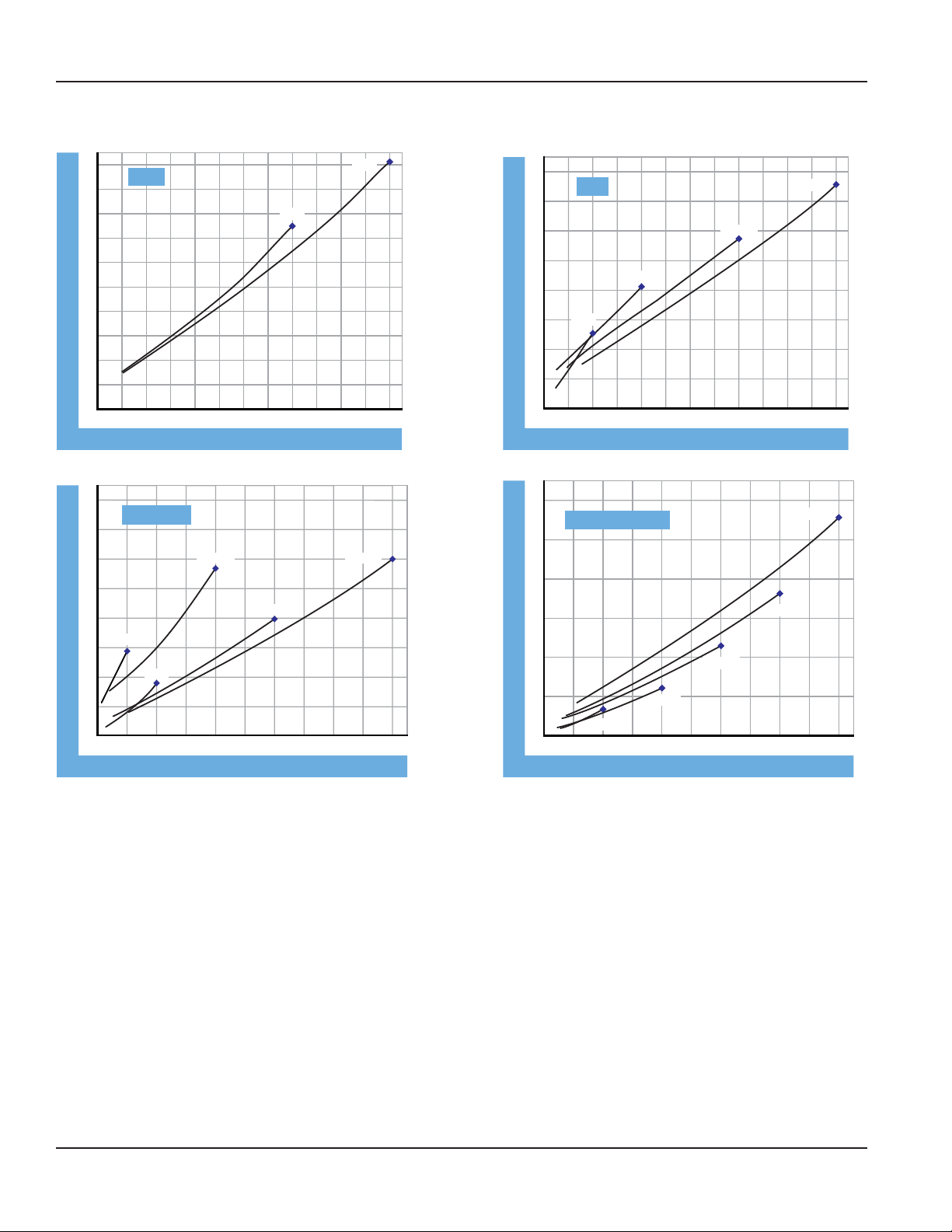
Flow vs Pressure Drop
Air/Caustic and Corrosive Gases
25
20
1/4"
2-20
15
10
5
PRESSURE DROP, PSI
0
0 105 15 20 25 30
FLOW, SCFM
20
3/4" / 1"
15
10
10-100
15-150
3-25
5
5-50
25-250
PRESSURE DROP, PSI
0
0 10050 150 200 250
FLOW, SCFM
3-30
20
15
1/2"
10-100
5-50
15-150
10
3-25
5
PRESSURE DROP, PSI
0
0 5025 75 100 125 150
FLOW, SCFM
30
1-1/4"/ 1-1/2"
100-1000
25
20
15
10
5
PRESSURE DROP, PSI
0
20-200
0 400200 600 800 1000
40-400
60-600
80-800
FLOW, SCFM
Page 34 February 2023
Page 35

WARRANTY/DISCLAIMER
OMEGA ENGINEERING, INC. warrants this unit to be free of defects in materials and workmanship for a period of 13
months from date of purchase. OMEGA’s WARRANTY adds an additional one (1) month grace period to the normal
one (1) year product warranty to cover handling and shipping time. This ensures that OMEGA’s customers receive
maximum coverage on each product.
If the unit malfunctions, it must be returned to the factory for evaluation. OMEGA’s Customer
Service Department will issue an Authorized Return (AR) number immediately upon phone
or written request. Upon examination by OMEGA, if the unit is found to be defective, it will
be repaired or replaced at no charge. OMEGA’s WARRANTY does not apply to defects resulting from any action of
the purchaser, including but not limited to mishandling, improper interfacing, operation outside of design limits,
improper repair, or unauthorized modification. This WARRANTY is VOID if the unit shows evidence of
having been tampered with or shows evidence of having been damaged as a result of excessive corrosion; or current, heat, moisture or vibration; improper specification; misapplication; misuse or other operating conditions outside of OMEGA’s control. Components in which wear is not warranted, include but are not
limited to contact points, fuses, and triacs.
OMEGA is pleased to offer suggestions on the use of its various products. However,
OMEGA neither assumes responsibility for any omissions or errors nor assumes liability for any damages that result from the
use of its products in accordance with information provided by OMEGA, either verbal or written. OMEGA warrants only that
the parts manufactured by the company will be as specified and free of defects. OMEGA MAKES NO OTHER WARRANTIES OR
REPRESENTATIONS OF ANY KIND WHATSOEVER, EXPRESSED OR IMPLIED, EXCEPT THAT OF
TITLE, AND ALL IMPLIED WARRANTIES INCLUDING ANY WARRANTY OF MERCHANTABILITY
AND FITNESS FOR A PARTICULAR PURPOSE ARE HEREBY DISCLAIMED. LIMITATION OF
LIABILITY: The remedies of purchaser set forth herein are exclusive, and the total liability of
OMEGA with respect to this order, whether based on contract, warranty, negligence,
indemnification, strict liability or otherwise, shall not exceed the purchase price of the
component upon which liability is based. In no event shall OMEGA be liable for
consequential, incidental or special damages.
CONDITIONS: Equipment sold by OMEGA is not intended to be used, nor shall it be used: (1) as a “Basic Component”
under 10 CFR 21 (NRC), used in or with any nuclear installation or activity; or (2) in medical applications or used on
humans. Should any Product(s) be used in or with any nuclear installation or activity, medical application, used on
humans, or misused in any way, OMEGA assumes no responsibility as set forth in our basic WARRANTY/DISCLAIMER
language, and, additionally, purchaser will indemnify OMEGA and hold OMEGA harmless from any liability or damage
whatsoever arising out of the use of the Product(s) in such a manner.
RETURN REQUESTS/INQUIRIES
Direct all warranty and repair requests/inquiries to the OMEGA Customer Service Department. BEFORE RETURNING
ANY PRODUCT(S) TO OMEGA, PURCHASER MUST OBTAIN AN AUTHORIZED RETURN (AR) NUMBER FROM OMEGA’S
CUSTOMER SERVICE DEPARTMENT (IN ORDER TO AVOID PROCESSING DELAYS). The assigned AR number should then
be marked on the outside of the return package and on any correspondence.
The purchaser is responsible for shipping charges, freight, insurance and proper packaging to prevent breakage in
transit.
FOR WARRANTY RETURNS, please have the
following information available BEFORE contacting
OMEGA:
1. Purchase Order number under which the product was
PURCHASED,
2. Model and serial number of the product under warranty, and
3. Repair instructions and/or specific problems
relative to the product.
OMEGA’s policy is to make running changes, not model changes, whenever an improvement is possible. This aords our customers the
latest in technology and engineering.
OMEGA is a registered trademark of OMEGA ENGINEERING, INC.
© Copyright 2023 OMEGA ENGINEERING, INC. All rights reserved. This document may not be copied, photocopied, reproduced, translated, or reduced to any electronic medium or machine-readable form, in whole or in part, without the prior written consent of OMEGA
ENGINEERING, INC.
FOR NON-WARRANTY REPAIRS,
current repair charges. Have the following information
available BEFORE contacting OMEGA:
1. Purchase Order number to cover the COST
of the repair,
2. Model and serial number of the product, and
3. Repair instructions and/or specific problems
relative to the product.
consult OMEGA for
Page 36

Where Do I Find Everything I Need for
Process Measurement and Control?
OMEGA…Of Course!
Shop online at omega.com
TEMPERATURE
• Thermocouple, RTD & Thermistor Probes, Connectors, Panels & Assemblies
• Wire: Thermocouple, RTD & Thermistor
• Calibrators & Ice Point References
• Recorders, Controllers & Process Monitors
• Infrared Pyrometers
PRESSURE, STRAIN AND FORCE
• Transducers & Strain Gages
• Load Cells & Pressure Gages
• Displacement Transducers
• Instrumentation & Accessories
FLOW/LEVEL
• Rotameters, Gas Mass Flowmeters & Flow Computers
• Air Velocity Indicators
• Turbine/Paddlewheel Systems
• Totalizers & Batch Controllers
SM
pH/CONDUCTIVITY
• pH Electrodes, Testers & Accessories
• Benchtop/Laboratory Meters
• Controllers, Calibrators, Simulators & Pumps
• Industrial pH & Conductivity Equipment
DATA ACQUISITION
•
Communications-Based Acquisition Systems
•
Data Logging Systems
•
Wireless Sensors, Transmitters, & Receivers
•
Signal Conditioners
•
Data Acquisition Software
HEATERS
• Heating Cable
• Cartridge & Strip Heaters
• Immersion & Band Heaters
• Flexible Heaters
• Laboratory Heaters
ENVIRONMENTAL
MONITORING AND CONTROL
• Metering & Control Instrumentation
• Refractometers
• Pumps & Tubing
• Air, Soil & Water Monitors
• Industrial Water & Wastewater Treatment
• pH, Conductivity & Dissolved Oxygen Instruments
M0000/2023
 Loading...